Preston Cinema Systems TR433 2.4 GHz Transceiver User Manual Antenna 2010 Page 1
Preston Cinema Systems Inc 2.4 GHz Transceiver Antenna 2010 Page 1
Contents
- 1. Users Manual
- 2. Antenna data sheet
Antenna data sheet
1
2400 –2483.5 MHz Single Band Antenna
(802.11 b/g, includes frequencies of Bluetooth, ZigBee, and Wi-Fi products)
Antenna Solutions
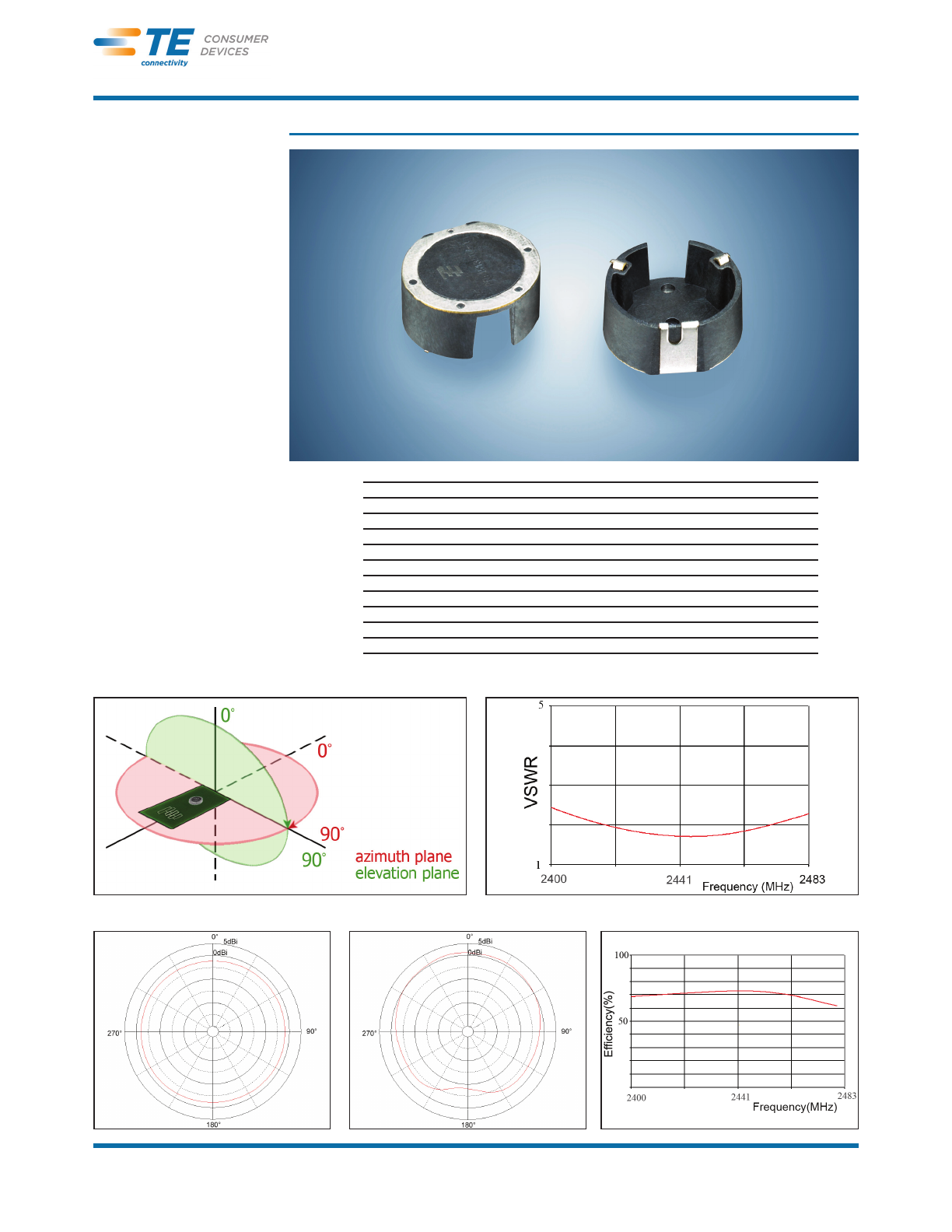
Part Number: 1513504-1
Product Facts
Wide bandwidth and high
gain in a compact size.
Enhanced hemispherical
pattern improves RF link
reliability of portable
devices.
Available in tape & reel.
RoHS compliant
Recommendations
Minimum or no matching
circuits required.
Bandwidth and performance
is dependent on ground
plane size. Suggested
minimum ground plane
length from the antenna
feed is 30 mm.
PCB ground is to be on top
layer.
Test Orientation in Free Space VSWR
Azimuth Elevation Efficiency
Specifications
Frequency Range (MHz) 2400 –2483.5
Peak Gain + 2 dBi
VSWR < 2.5:1
Reflow Temperature 275°C maximum
Polarization Linear
Power Handling 10 Watt cw
Feed Point Impedance 50 Ohms unbalanced
Size 16.00 mm dia. x 6.05 mm
Weight < 1 g.
Mounting Surface-mount technology. See page 2
Keep Out Area See diagram on page 2
Legend:
2460 MHz
Legend:
2460 MHz
Catalog 4-1773459-1 Dimensions are in inches and Dimensions are shown for USA: 1-800-522-6752 UK: +44 (0) 800-267666
Revised 03-11 millimeters unless otherwise reference purposes only. Canada: 1-905-475-6222 Netherlands: +31 (0) 73-6246-999
sspecified. Values in brackets Specifications subject Germany: +49 (0) 6251-133-1999 China: +86 (0) 400-820-6015
www.te.com are metric equivalents. to change. For other country number go to te.com/supportcenter
www.antenna.te.com
2
PageHead_12_HelvCdBd (Continued)
Antenna Solutions
2400 –2483.5 MHz Single Band Antenna
(802.11 b/g, includes frequencies of Bluetooth, ZigBee, and Wi-Fi products)
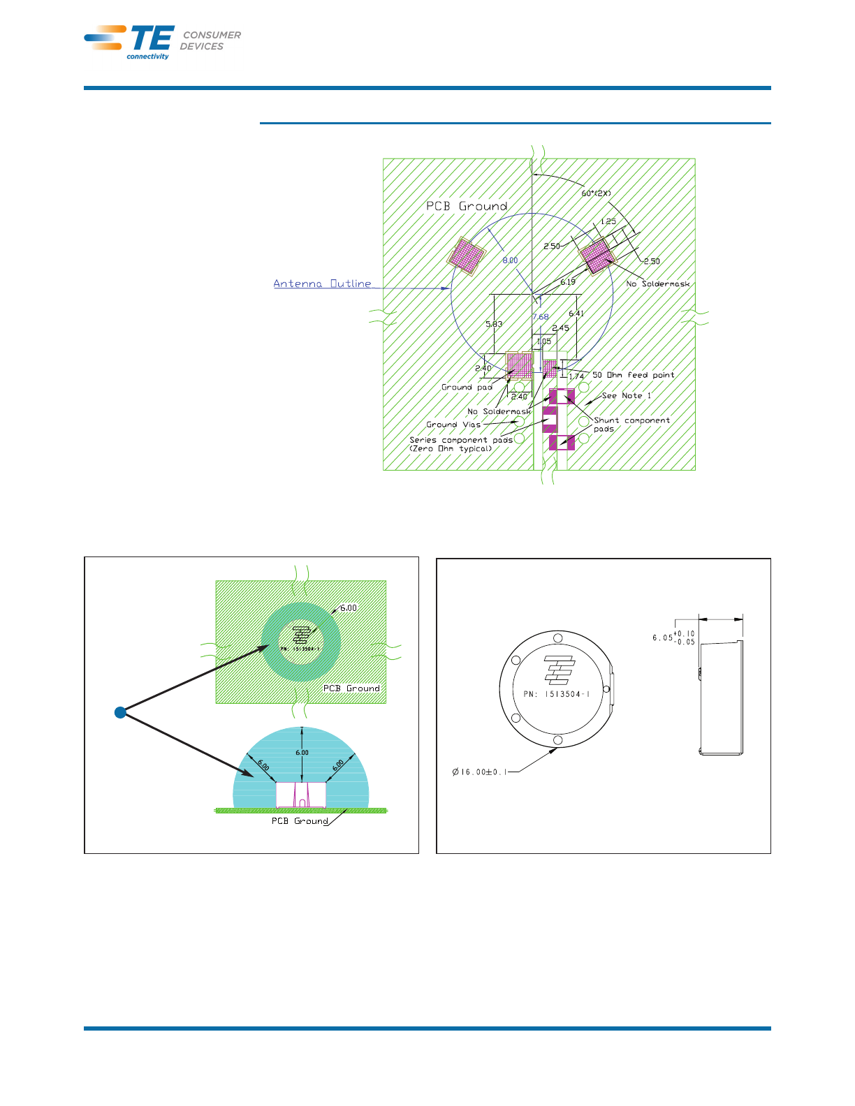
Part Number: 1513504-1
Keep Out Area Approx. Dimensions
Mounting Guide
NOTES: 1. Suggested matching component pads.
2. For more information please call TE.
Dimensions: mm
Diagram is not to scale
Dimensions: mm
Diagram is not to scale
Dimensions: mm
Diagram is not to scale
Keep Out Area
© 2011 Tyco Electronics Corporation. All Rights Reserved.
4-1773459-1–CIS–PDF–03-11
TE (logo) and TE Connectivity are trademarks of the TE Connectivity group
of companies and its licensors.
Other logos, product and Company names mentioned herein may be trade-
marks of their respective owners.
ZigBee is a trademark of ZigBee Alliance.
Bluetooth is a trademark of Bluetooth SIG, Inc.
"Wi-Fi" is a trademark of Wi-Fi Alliance.
Catalog 4-1773459-1 Dimensions are in inches and Dimensions are shown for USA: 1-800-522-6752 UK: +44 (0) 800-267666
Revised 03-11 millimeters unless otherwise reference purposes only. Canada: 1-905-475-6222 Netherlands: +31 (0) 73-6246-999
sspecified. Values in brackets Specifications subject Germany: +49 (0) 6251-133-1999 China: +86 (0) 400-820-6015
www.te.com are metric equivalents. to change. For other country number go to te.com/supportcenter
www.antenna.te.com
While TE has made every reasonable effort to ensure the accuracy of the information in this cata-
log, TE does not guarantee that it is error-free, nor does TE make any other representation, war-
ranty or guarantee that the information is accurate, correct, reliable or current. TE reserves the
right to make any adjustments to the information contained herein at any time without notice. TE
expressly disclaims all implied warranties regarding the information contained herein, including,
but not limited to, any implied warranties of merchantability or fitness for a particular purpose.
The dimensions in this catalog are for reference purposes only and are subject to change without
notice. Specifications are subject to change without notice.
Consult TE for the latest dimensions and design specifications.
9565 Soquel Drive
Aptos, CA 95003
(+ 831) 662-1174
http://www.antenna.te.com
– 1 –Revised 1/15/15
Product Description
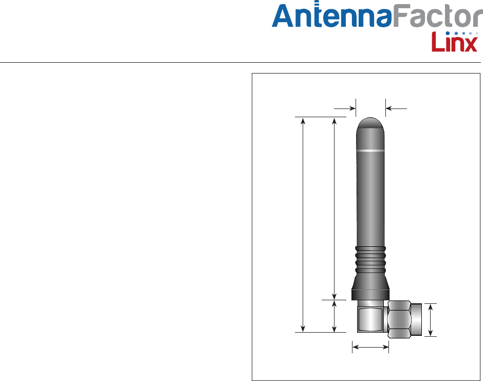
The RCS Series is ideally suited for products
requiring an attractive, yet compact, ¼-wave
antenna in a right-angle form factor. The antennas
attach via a standard SMA or Part 15 compliant
RP-SMA connector.
Features
• Reduced height helical whip
• Right-angle mount
• Excellent performance
• Omni-directional pattern
• Fully weatherized
• SMA or Part 15 compliant RP-SMA connector
• Use with plastic* or metal enclosures
* Requires proximity ground plane
Electrical Specications
Center Frequency: 2.45GHz
Recom. Freq. Range: 2.35–2.50GHz
Wavelength: ¼-wave
VSWR: < 1.9 typical at center
Peak Gain: –0.2dBi
Impedance: 50-ohms
Oper. Temp. Range: –20°C to +85°C
Connector: SMA or RP-SMA
Electrical specifications and plots measured on 10.16 cm x
10.16 cm (4.00" x 4.00") reference ground plane
ANT-2.4-CW-RCS-xxx
Data Sheet by
Ordering Information
ANT-2.4-CW-RCS (with RP-SMA connector)
ANT-2.4-CW-RCS-SMA (with SMA connector)
9.4 mm
(0.37")
8.5 mm
(0.33")
7.0 mm
(0.28")
45.0 mm
(1.77")
53.5 mm
(2.11")
8.0 mm
(0.31")
– 2 –
by
Data Sheet ANT-2.4-CW-RCS-xxx
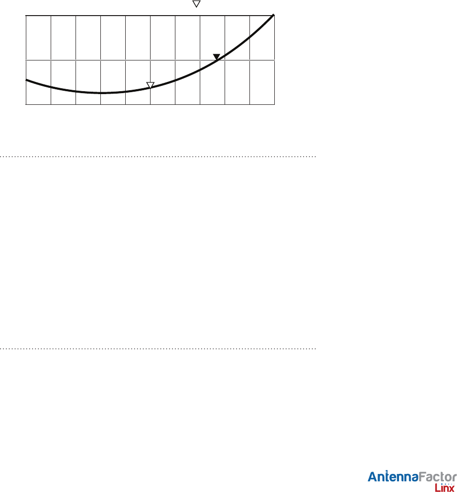
VSWR Graph
What is VSWR?
The Voltage Standing Wave Ratio (VSWR) is a measurement of how well
an antenna is matched to a source impedance, typically 50-ohms. It is
calculated by measuring the voltage wave that is headed toward the load
versus the voltage wave that is reflected back from the load. A perfect
match will have a VSWR of 1:1. The higher the first number, the worse the
match, and the more inefficient the system. Since a perfect match cannot
ever be obtained, some benchmark for performance needs to be set. In
the case of antenna VSWR, this is usually 2:1. At this point, 88.9% of the
energy sent to the antenna by the transmitter is radiated into free space
and 11.1% is either reflected back into the source or lost as heat on
the structure of the antenna. In the other direction, 88.9% of the energy
recovered by the antenna is transferred into the receiver. As a side note,
since the “:1” is always implied, many data sheets will remove it and just
display the first number.
How to Read a VSWR Graph
VSWR is usually displayed graphically versus frequency. The lowest point
on the graph is the antenna’s operational center frequency. In most cases,
this will be different than the designed center frequency due to fabrication
tolerances. The VSWR at that point denotes how close to 50-ohms the
antenna gets. Linx specifies the recommended bandwidth as the range
where the typical antenna VSWR is less than 2:1.
Counterpoise
Quarter-wave or monopole antennas require an associated ground plane
counterpoise for proper operation. The size and location of the ground
plane relative to the antenna will affect the overall performance of the
antenna in the final design. When used in conjunction with a ground
plane smaller than that used to tune the antenna, the center frequency
typically will shift higher in frequency and the bandwidth will decrease.
The proximity of other circuit elements and packaging near the antenna
will also affect the final performance. For further discussion and guidance
on the importance of the ground plane counterpoise, please refer to Linx
Application Note AN-00501: Understanding Antenna Specifications and
Operation.
VSWR Reflected Power
3:1
2:1
1:1
25%
11%
0%
2450MHz 2550MHz2350MHz
1.394