Prime Electronics and Satellitics WA254T WLAN module User Manual WA254TManual
Prime Electronics & Satellitics Inc. WLAN module WA254TManual
User Manual

33333333
百一電子股份有限公司
Prime Electronics & Satellitics Inc.
WLAN Module WA254T
User Manual

Specification
No. Item Condition Min. Typ. Max.
Test Method/Condition
1. General specification
1-1. Standard IEEE 802.11b
1-2. Frequency Band(MHz) 2400 2497
1-3. No. of Selectable
Channels
11 Channels (US, Canada)
13 Channels (Europe)
14 Channel (Japan)
1-4. Channel Spacing (MHz) 5
1-5. Modulation Technique DSSS (CCK, DQPSK, DBPSK)
1-6. Spreading 11-chip Barker Sequence
1-7. Media Access Protocol CSMA/CA(collision Avoidance) with ACK
1-8. Interface 60 pin connector
1-9. Reset Switch Push for normal reset
1-10. LED Indicators Power : Green for Power ON
Ethernet : Green for Link ,Blink for active
WLAN :Green Blinking for Active
1-11. Antenna One External 2 dBi Dipole Antenna
1-12. Dimensions 110 x 37 x 8 mm
2. Standard Test Condition
2-1. Supply voltage(V)
4.5
3. Electrical
Specification
Temperature Range:0 ~ 55℃
Humidity:95 % (Non-condensing)
470 550 Receiver Mode
3-1. Power Consumption
(mA)
@+4.5V
650 750 Transmit Mode
-76 -78 -82 @ 11 Msps ,Through-Put > 4 Mbps
-78 @ 5.5 Msps
-81 @ 2 Msps
3-2 Receive Sensitivity
(dBm)[FER < 8%]
-84 @ 1 Msps
30 @ 11 Msps Indoor
100 @ 1 Msps
150 180 250 @ 11 Msps
3-3. Range(Meters)
Outdoor
300 @ 1 Msps
3-4. Average Output Power(dBm) Ch1~Ch13 14 15 18
@30 dBc difference between the signal level at center
frequency and higher first side lobe
Ch 14 14 15 18
@25 dBc difference between the signal level at center
frequency and higher first side lobe
3-5 Frequency Accuracy(ppm) - 25 + 25

4. Frequency channel plan
Regulation Domains
Channel_ID Frequency
(Mhz)
FCC
(0x00)
IC
(0x01)
ETSI
(0x02)
Spain
(0x03)
France
(0x04)
MKK
(0x05)
MKK2
(0x06)
1 2412 X X X X
2 2417 X X X X
3 2422 X X X X
4 2427 X X X X
5 2432 X X X X
6 2437 X X X X
7 2442 X X X X
8 2447 X X X X
9 2452 X X X X
10 2457 X X X X X X
11 2462 X X X X X X
12 2467 X X X
13 2472 X X X
14 2484
X X
Copyright
Copyright 2001 by this company. All rights reserved. No part of this publication may be reproduced,
transmitted, transcribed, stored in a retrieval system, or translated into any language or computer
language, in any form or by any means, electronic, mechanical, magnetic, optical, chemical, manual or
otherwise, without the prior written permission of this company
This company makes no representations or warranties, either expressed or implied, with respect to the
contents hereof and specifically disclaims any warranties, merchantability or fitness for any particular
purpose. Any software described in this manual is sold or licensed "as is". Should the programs prove
defective following their purchase, the buyer (and not this company, its distributor, or its dealer) assumes
the entire cost of all necessary servicing, repair, and any incidental or consequential damages resulting
from any defect in the software. Further, this company reserves the right to revise this publication and to
make changes from time to time in the contents hereof without obligation to notify any person of such
revision or changes.
All brand and product names mentioned in this manual are trademarks and/or registered trademarks of
their respective holders.
Federal Communication Commission
Interference Statement
This equipment has been tested and found to comply with the limits for a Class B digital device, pursuant
to Part 15 of FCC Rules. These limits are designed to provide reasonable protection against harmful
interference in a residential installation.
This equipment generates, uses, and can radiate radio frequency energy and, if not installed and used in
accordance with the instructions, may cause harmful interference to radio communications.
However, there is no guarantee that interference will not occur in a particular installation. If this
equipment does cause harmful interference to radio or television reception, which can be determined by
turning the equipment off and on, the user is encouraged to try to correct the interference by one or more
of the following measures:
1. Reorient or relocate the receiving antenna.
2. Increase the separation between the equipment and receiver.
3. Connect the equipment into an outlet on a circuit different from that to which the receiver is connected.
4. Consult the dealer or an experienced radio technician for help.
FCC Caution
This equipment complies with FCC radiation exposure limits. However, in order to avoid the possibility of
exceeding the FCC exposure limits, this device and its antenna should not be co-located or operating in
conjunction with any other antenna or transmitter.”
This device complies with Part 15 of the FCC Rules. Operation is subject to the following two conditions:
(1) this device may not cause harmful interference, and (2) this device must accept any interference
received, including interference that may cause undesired operation.
Any changes or modifications not expressly approved by the party responsible for compliance could void
the authority to operate equipment.
This device is intended only for OEM integrators under the following conditions:
1) The antenna must be installed such that 20 cm is maintained between the antenna and users, and
2) The transmitter module may not be co-located with any other transmitter or antenna.
As long as the 2 conditions above are met, further transmitter test will not be required. However, the OEM integrator is
still responsible for testing their end product for any additional compliance requirements required with this module
installed (for example, digital device emissions, PC peripheral requirements, etc.).
IMPORTANT NOTE: In the event that these conditions cannot be met (for example certain laptop configurations or
co-location with another transmitter), then the FCC authorization is no longer considered valid and the FCC ID cannot be
used on the final product. In these circumstances, the OEM integrator will be responsible for re-evaluating the end
product (including the transmitter) and obtaining a separate FCC authorization.
End Product Labeling
This transmitter module is authorized only for use in device where the antenna may be installed such that 20 cm may be
maintained between the antenna and users (for example, access points, routers, wireless ADSL modems, and similar
equipment). The final end product must be labeled in a visible area with the following: "Contains TX FCC ID:
PQP-WA254T".
Manual Information for End Users
The end user must not have manual instructions to remove or install the device. The user manual for end users must
include the following information in a prominent location.
"IMPORTANT NOTE:
To comply with FCC RF exposure compliance requirements, the antenna used for this transmitter must be installed to
provide a separation distance of at least 20 cm from all persons and must not be co-located or operating in conjunction
with any other antenna or transmitter."
R&TTE Compliance Statement
This equipment complies with all the requirements of DIRECTIVE 1999/5/CE OF THE EUROPEAN
PARLIAMENT AND THE COUNCIL of March 9, 1999 on radio equipment and telecommunication
terminal Equipment and the mutual recognition of their conformity (R&TTE)
The R&TTE Directive repeals and replaces in the directive 98/13/EEC (Telecommunications Terminal
Equipment and Satellite Earth Station Equipment) As of April 8, 2000.
Safety
This equipment is designed with the utmost care for the safety of those who install and use it. However,
special attention must be paid to the dangers of electric shock and static electricity when working with
electrical equipment. All guidelines of this and of the computer manufacture must therefore be allowed at
all times to ensure the safe use of the equipment.
EU Countries Intended for Use
The ETSI version of this device is intended for home and office use in Austria Belgium, Denmark,
Finland, France, (with Frequency channel restrictions) Germany, Greece, Ireland, Italy, Luxembourg, the
Netherlands, Portugal, Spain, Sweden, and the United Kingdom.
The ETSI version of this device is also authorized for use in EFTA member states: Iceland, Liechtenstein,
Norway, and Switzerland.
EU Countries Not intended for use
None.
Potential restrictive use
France: Only channels 10, 11, 12, and 13
Configuring the Wireless LAN Module
The APM Utility helps you configure the Wireless LAN Module through the Ethernet port.
3.1 Installing the APM Utility
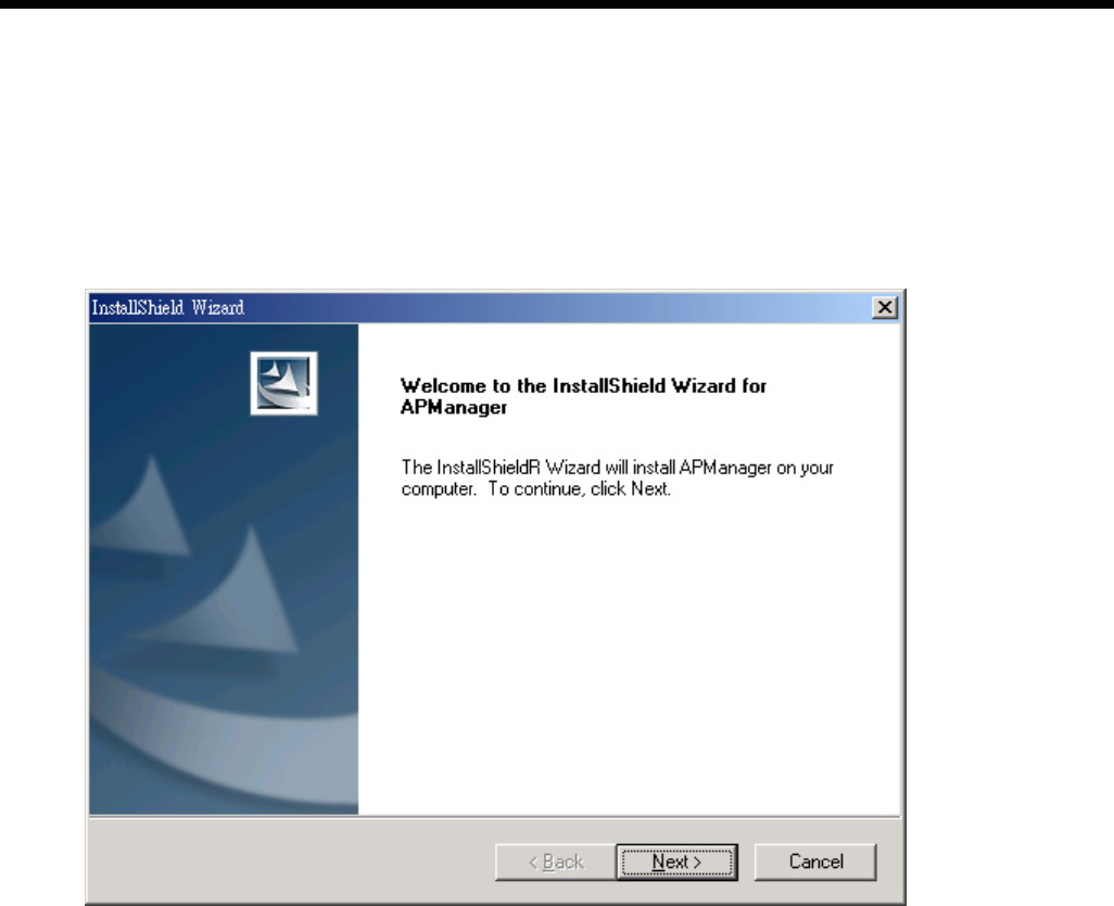
A. Power on your computer and allow Window 98/Me/2000/XP to load fully. Insert the driver CD into
the CD-ROM and execute the “Setup.exe” program. (It may be found in the APM folder.) The
wizard box will then appear, click “Next” to continue.
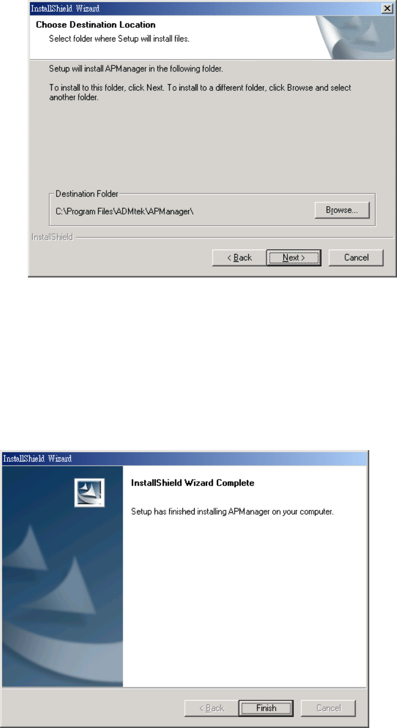
B. Click “Browse” to choose the folder where you want to locate the driver, click “Next”.
C. After Windows finishes copying files, it will show that “Setup has finished installing APManager
on your computer.” Click “Finish” to complete the procedure.
D. Connect the AP to the Ethernet port and boots up the APM utility to start the configuration.
3.2 Configuring the Wireless LAN Module with the APManager
On the Windows Start Menu, choose “Start Programs” -> “APManager” Using this option you can
directly connect to the AP.
● Find the Module
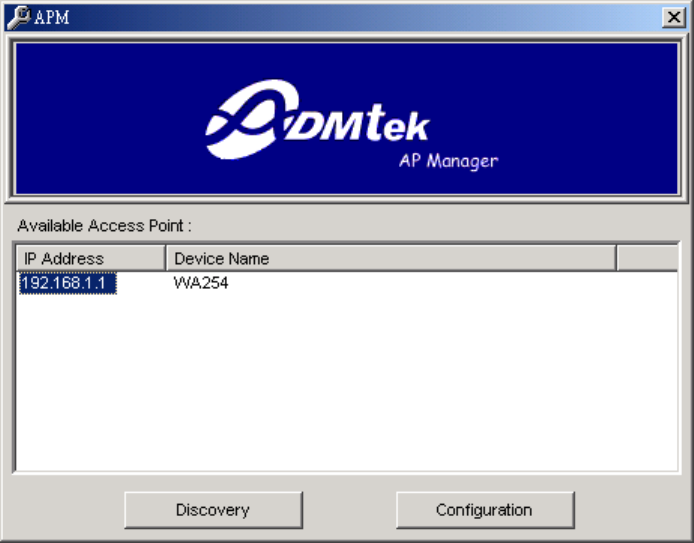
1) This submenu allows you to find and connect to the Module without knowing its IP address. Click
“Discovery” in order to find the Module. Window appears indicating the IP Address of the Module
and select “IP Address”. Then click “Configuration” to configure the Module.
Note: In order to find Module, Module and computers must resident in the same subnet. The default IP of
Module is “192.168.1.1”. You will also need to set your IP address of your PC to “192.168.x.x” and
subnet to “255.255.0.0”.
2) It indicates a successful connection to the Module if the dialog below appears. Enter password
and press “OK”. (Default Password : private)
3) It indicates an unsuccessful connection to AP if the below error message appears. Please check
whether the Module has an appropriate IP address and has been connected to the network.
● Table Menu
The table menu contains the following enabled submenus:
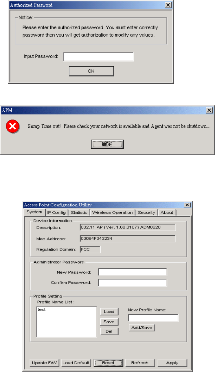
1) System:
□ Device
Information:show the description, Mac address, Regulation Domain.
□ Administrator Password:change the password that APM control Module.
□ Profile Name List:Using “Add/Save” button to add new profile name;using “Load”, “Save”,
“Del” button to modify the profile name.
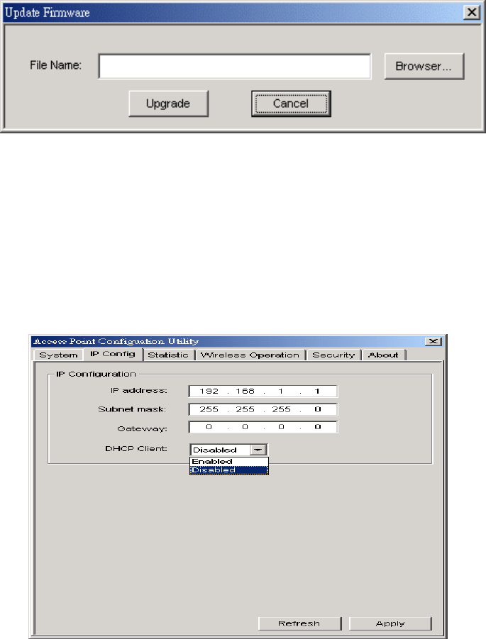
□ Update F/W:Click the button to update the firmware of Module.
Click “Browser” to choose .dlf firmware, then click “Upgrade” button to update firmware.
□ Load Default:Click the button to assign the default data.
□ Reset:Click the button to reset the Module.
□ Refresh:Click the button to reload the data from Module.
□ Apply:Click the button to assign new data to Module.
2) IP Config:
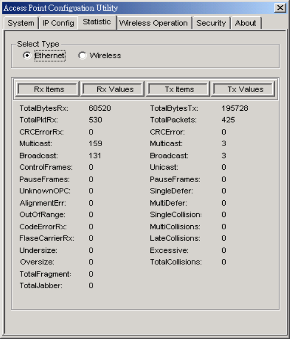
In this page you can see and change the IP Address, IP Mask and Gateway of the Module.
3) Statistic:
In this page you can see the statistic of the Module linking in Ethernet or Wireless.
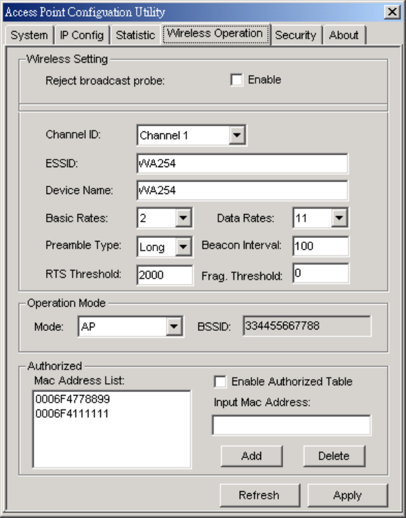
4) Wireless Operation:
Using this option you can either view or modify the Wireless LAN parameters of the Module. These
parameters are described below:
□
□
□
□
□
□ Wireless Setting:
Reject broadcast probe: When checked the Module broadcasts the ESSID to the stations, if
not checked then the stations must know the Module ESSID in advance.
Channel ID: There are 14 channels available. The channels differ from country to country.
Select the channel to be used.
ESSID: It is an ASCII string up to 32 characters used to identify a WLAN that prevents the
unintentional merging of two co-located WLANs. The ESSID value must be the same in all
stations and AP in the extended WLAN. Select the ESSID to be used.
Device Name: The name of the Module.
Rate: By default the unit adaptively selects the highest possible rate for transmission. Select
the Basic & Data rates to be used among the following options: 1, 2, 5.5, 11(Mbps).
Preamble Type (Short / Long): Preamble is the first sub-field of the PPDU. It’s an
appropriable frame format for transmission between PHY (Physical layer). There are two
preamble types: short and long. The Short Preamble option improves throughput performance.
Beacon Interval: Set the Beacon Period parameter, which specifies the duration between
Beacon packets (milliseconds). The range for the Beacon Period is between the range
20-1000 with a typical value of 100.
RTS Threshold: Minimum packet size to require an RTS Request To Send. For packets
smaller than this threshold, an RTS is not sent and the packet is transmitted directly to the
WLAN. This is the option for the RTS Threshold activation.
Frag. Threshold: The size at which packets will be fragmented. Choose a setting within a
range of 256 to 2346 bytes.