Prime Electronics and Satellitics WP222MF00001 Wireless PCMCIA LAN Card User Manual WP222M UserMan

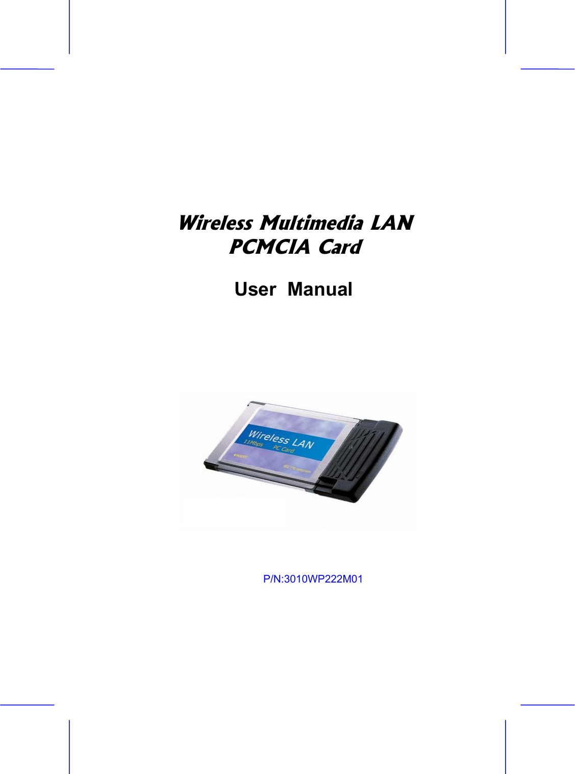
Prime Electronics & Satellitics Inc. Wireless PCMCIA LAN Card WP222M UserMan

Users Manual

Wireless Multimedia LANPCMCIA CardUser  Manual   P/N:3010WP222M01
Wireless PCMCIA Card CopyrightCopyright  ¤  2001 by this company.  All rights reserved.  No part of this publication may be reproduced, transmitted, transcribed, stored in a retrieval system, or translated into any language or computer language, in any form or by any means, electronic, mechanical, magnetic, optical, chemical, manual or otherwise, without the prior written permission of this company. This company makes no representations or warranties, either expressed or implied, with respect to the contents hereof and specifically disclaims any warranties, merchantability or fitness for any particular purpose.  Any software described in this manual is sold or licensed "as is".  Should the programs prove defective following their purchase, the buyer (and not this company, its distributor, or its dealer) assumes the entire cost of all necessary servicing, repair, and any incidental or consequential damages resulting from any defect in the software.  Further, this company reserves the right to revise this publication and to make changes from time to time in the contents hereof without obligation to notify any person of such revision or changes..All brand and product names mentioned in this manual are trademarks and/or registered trademarks of their respective holders.
Wireless Access Point   2Federal  Communication Commission Interference StatementThis equipment has been tested and found to comply with the limits for a Class B digital device, pursuant to Part 15 of FCC Rules.  These limits are designed to provide reasonable protection against harmful interference in a residential installation.  This equipment generates, uses, and can radiate radio frequency energy and, if not installed and used in accordance with the instructions, may cause harmful interference to radio communications.  However, there is no guarantee that interference will not occur in a particular installation.  If this equipment does cause harmful interference to radio or television reception, which can be determined by turning the equipment off and on, the user is encouraged to try to correct the interference by one or more of the following measures:1.  Reorient or relocate the receiving antenna. 2.  Increase the separation between the equipment and receiver. 3.  Connect the equipment into an outlet on a circuit different from that to which the receiver is connected. 4.  Consult the dealer or an experienced radio technician for help. Notice 1: The changes or modifications not expressly approved by the party responsible for compliance could void the user's authority to operate the equipment. Notice 2: Shielded interface cables, if any, must be used in order to comply with the emission limits. FCC RF Radiation Exposure Statement This equipment complies with FCC RF radiation exposure limits set forth for an uncontrolled environment. This equipment should be installed and operated with a minimum distance of 20cm between the radiator and your body.
Wireless PCMCIA Card  Manual Contents Chapter  1  Introduction1.1   Package Content  ......................................................1-1 1.2   System Requirement .................................................1-1 1.3        Feature ………………………….………………………  1-2Chapter  2  Installation2.1   Hardware/OS requiements  .......................................2-1 2.2   Installing the hardware  ..............................................2-1 2.3   Installing the hardware drivers  ..................................2-2  Chapter  3  Installing the Network Manager software …..………………………………………3-1Chapter  4  Using the Network4.1   Device Managemet   .................................................4-1 4.2   Bridge Access Point   .................................................4-4 4.3   Network Management   ..............................................4-4 4.4   Enrolling a Bridge Access Point into the netwrok  .....4-5  4.5   Adding additional nodes   ...........................................4-7  4.6   Bridge Manager  ........................................................4-74.7   Using WEP   ...............................................................4-9 4.8   Tip on using the Network  ........................................4-10  Chapter  5  Uninstall5.1  Windows 98,Me,and Windows 2000……………………5-1
Chapter1IntroductionIntroduction   1-1 Thank you for purchasing the Wireless Multimedia PCMCIA Card. It offered a unprecedented multimedia wireless solution and provided the simultaneous multimedia audio and video stream without any other network activity. You may use the device to extends Cable/DSL connection and existing Ethernet network without any wires. This manual guides you on how to install and properly use the Wireless Access Point in order to take full advantage of its features. 1.1 Package Contents Make sure that you have the following items: x One Wireless PCMCIA Cardx One Installation Manualx  One CD-Title with AP manager SoftwareIf any of the above items are missing, contact your supplier as soon as possible.1.2 System Requirements Before installation, please check the following requirements with your equipment.x Pentium Based ( And Above ) IBM-Compatible PC System x CD-ROM drive
1-2 Introduction x One PCMCIA Slot Interface x Windows 9x/ME/NT4.0/2000 Operating System with TCP/IP protocol1.3 Features   Wi-Fi (IEEE 802.11b) Certification and Interoperability with Wireless LAN Standards  IEEE 8021.b & IEEE 802.11e-class Compliant  11 Mbps Transmission Rate  Rugged Metal Design with Integrated Antenna  Contention-Free Access and Dynamic Stream support  Parameterized Quality of Service (QoS) to Support Multimedia Distribution and Ensure Delivery of Isochronously /Time-Dependent Content  Excellent Interference Immunity  Peer-to-Peer Communication among Multiple Devices for Efficient Bandwidth Utilization  Forward Error Correction to Repair Corrupted Packets “ On The Fly ” during Transmission  Channel Agility to Avoid In-Band Interference from Household Appliances, such as Microwave Ovens and Cordless Phones
Introduction   1-3  Better Range and Fade Margin for Coverage Throughout The Home  Open Enrollment for Easily Adding Devices to The Network  Coordinator Redundancy to Prevent Single Point of Failure  Delayed Acknowledgement Improves Payload Efficiency and Minimizes Overhead for Network Access 1.4 Specification  ΘʳStandard     Wi-Fi (IEEE802.11b) and QoSΘʳ                                     ( IEEE802.11e-class) ΘʳSignal Type     DSSS (Direct Sequence Spread Spectrum) ΘʳModulation      QPSK / BPSK / CCK  ΘʳPort        PCMCIA  Type II ΘʳAntenna      Built-in dielectric antenna  ΘʳData Encryption     40 bit WEP encryption ,          128 bit KEY Length(otional) ΘʳFrequency     2.4GHz –2.4835GHz  ΘʳChannel       11 Channels(US,Canada)                    13 Channels(Europe)      14 Channel(Japan) ΘʳData Rate       Up to 11Mbps(with automatic scale back)
1-4 Introduction ΘʳTransmit Power  Guaranteed 15 dBm , Typically 18 dBm ΘʳReceive Sensitively   Guaranteed –76 dBm , Typically –80 dBm LED Indicators  Link Status Power   Host Power                                         ΘʳTemperature   Operating :0Ƭ to 55Ƭ,Storage : -20к to 70к,ΘʳHumidity   95% Non-Condensing ΘʳDimensions   110x54x6mm
Chapter2InstallationInstallation    2-1 Before you proceed with the installation, it is necessary that you have enough information about the Wireless PCMCIA Card  2.1  Hardware/OS requirements  ΘʳPentium II PC Θʳ   64 MB RAM Θʳ   Windows 98/ME/2000 2.2  Installing the hardware   NOTE: Before installing, please remove any prior versions using the instructions under “Uninstall.” (See Uninstallon page 5-1) ¾ The PCMCIA card (a.k.a. PC card) has built-in Radio and antenna attached to one side of the regular PC card form factor. The physical dimension of the PC card may come in contact with other PC card attachment directly above. Inserting the PC card on the upper slot would avoid such contact. Note that the below image of the PCMCIA card may look different from your PCMCIA card.
2-2 Installation 2.3  Installing the hardware driversThe examples shown reflect a Windows 2000 operating system. The actual installation screens may be slightly different on different Windows OS versions. Perform the following steps to install the wireless adapter. You may need your Windows CD during the configuration.¾ Before installation, it is recommended to close all applications first.¾ Once the PCMCIA Adapter is inserted, Windows will detect the new hardware with a pop up window. Then the hardware wizard dialog box will appear to facilitate hardware installation. It will notify you of the detection of the adapter.
Installation 2-3 ¾ Windows 2000 may display a “Digital Signature Not Found”message because the PCMCIA adapter does not contain a Microsoft digital signature. This does not affect the wireless functionality. Click on “Yes” to continue.¾ Windows 2000 will prompt for Driver source CD. Insert the installation CD into your CDROM drive and click “OK”.¾ At the “Files Needed” panel, click on “Browse” to select the “\NIC\install on W2K” folder location on the CD. Be sure to
2-4 Installation browse to the exact location of the Windows drivers for you operating system (i.e Windows 98, 2000 or Millennium). Do not use the automatic search option to locate the drivers, as it will automatically default to the wrong Windows driver which will cause installation to fail.¾ Windows hardware wizard will confirm that PCMCIA wireless driver has been installed.¾ When completed click ‘Finish’. You will next be asked to reboot the computer. Click ‘Yes’.
Installation 2-5 Note: If the system does not shut down (or restart) within 2 minutes manually power down the computer and then power it back up againThis completes the hardware portion of the installation. Note: If this is the first time a network device as been installed, after re-starting the system, you may need to enter a Windows network ‘User name’ and ‘Password’.
Chapter3Installing the Network Manager softwareConfiguring                                                                                      3-1 This section covers the installation of the network management, device management and Bridge Manager software. Do not proceed with this section until you have installed the appropriate hardware as described in the previous sections. ¾ The Network Management Setup starts automatically when the computer reboots. Click ‘Next’ to start the Network Management Software installation.
3-2 Configuring ¾ The next screen in this installation (not shown) is a placeholder for the licensing agreement. To continue click “Yes” to agree to the license agreement. ¾ In the registration screen enter your Name, Company, and‘ShareWave’ as the Serial number.Click ‘Next’ to continue.¾ Here you are given the opportunity to select the Destination ofwhere you wish to install the program files. It is recommended that you keep the default path.Click ‘Next’ to continue.
Configuring   3-3 ¾ Enter a Network ID (name) for the wireless network security identification. This name is used to generate a security ID for enrollment into the local wireless network. Note: all nodes enrolled into the wireless network must have the sameNetwork ID Click ‘Next’ to begin the process of installing the NetworkManagement software.¾ The below message box will indicate that the system configuration parameters entered during the installation have been successfully uploaded to the flash memory. Click ‘OK’. The installation is now complete.
Chapter4Using the NetworkUsing the Network  4-1 4.1  Device Management  If the icon does not appear in the system tray, double-click the icon on the desktop. The icon in the system tray offers additional information by a right click option ‘Open Device management Dialog’. ΘʳFigure 1 Device Management Application
4-2  Using the Network The Bodega Device Manager introduces the “Profiles” concept. Profiles allow a user to store specific settings for a particular situation or environment. A user may have an “Office” profile in which the node operates in Wi-Fi mode and a “Home” profile for Multimedia mode, for instance. Profiles will help the user manage the appropriate settings including network IDs, WEP, and operating mode. Profiles can be created, managed (for editing) and activated from the Device Manager application by selecting the Profiles menu.When creating a new profile from this menu, the software will ask the user to select either a Wi-Fibased or a Multimedia-based profile. ΘʳFigure 2 Creating a Multimedia ProfileFigure 2 shows the screen to create a new Multimedia profile. Both settings that are common between Wi-Fi and Multimedia mode (such as Profile Name and encryption setting) and any settings unique to Multimedia mode can be set here. Unique settings include the “Auto” setting for the channel selection and the Channel Agility sensitivity setting (both unique to the Channel Agility feature). Another Multimedia-only setting is the “Fix as Master” option, which forces a particular node to be the network coordinator. 
Useing the Network   4-3 ΘʳFigure 3 Creating a WiFi ProfileFigure 3 shows the WiFi profile “create” screen. The WiFi-unique options that can be set on this screen are the Network and Node type settings in addition to Data Rate and Power Management settings. Once two or more profiles are created, the user can switch between these profiles using the Profiles menu in the main device manager screen.ΘʳFigure 4 Managing Profiles
4-4  Using the Network Figure 4 displays the Manage Profiles screen in which previously created profiles can be edited, deleted,renamed and copied. The Copy command is useful in creating multiple profiles that are similar without having to reset all options manually. 4.2  Bridge Access Point  As described in the previous paragraph, nodes can be switched from Wi-Fi to multimedia mode (and vice versa) using the device manager software. As the Access Point/Bridge does not have a user interface that can be used to switch between multimedia and Wi-Fi, it employs a manual mode switch. This switch can be found on the AP and is labeled accordingly.ΘʳMode Switch – Used to switch between Multimedia (WhiteCap) and Wi-Fi mode (Wi-Fi = In; Multimedia = Out) ΘʳFactory Default Reset – Used to reset all parameters (i.e. SSID, WEP etc) to the factory default ΘʳController Reset – Used to reset the BAP (similar to power cycling) ΘʳPower – Connects to (included) power adapter ΘʳEthernet Port – Connects to HUB for LAN / Internet connectivity ΘʳUSB Port – Connects to connector, use for configuration only (Bridge Manager software required) 4.3 Network Management The Network Manager will start automatically once you logon to Windows. The icon in the Windows Tray will appear when the Network Management software is running. From this Icon the earlier described Device Management and network management application can be started (right-click on the icon). Note that the Network Management Application is ONLY available
Useing the Network   4-5 when the Network is in Multimedia mode.Double clicking on the icon in the system tray brings up the network management utility in your browser. Note: This utility requires Microsoft’s Internet Explorer with Java™ technology enabled. If TCP/IP is not installed, you will not be able to use network management utilities.The ‘Node Information’ page in network management utility displays a diagram of the active Multimedia network. Additional information is also available by clicking on buttons to the left side of the page. The Color legend on the lower left designates the quality of the connection and is indicated by the color of the lines between any two nodes. The information on this page is obtained from the Master node for all nodes on the network. If the Master node is a non-functional node this HTML page will not be available on the client nodes and a “troubleshooting page” will be displayed instead. 4.4  Enrolling a Bridge Access Point into the networkTo add a Bridge node to the network the designated Master node must allow the Bridge to be “enrolled” into its secured network group. This
4-6  Using the Network “group” is based on the network identification (or ‘Network ID’) entered during installation. If the Network ID of a node matches the master’s Network ID, the node will be automatically enrolled into the group. To add a Wireless Bridge to the network or add a new node which is configured to be in an open enrollment mode, click on the ‘Add A New Node’ button in the Network Management page from any node in the system. The Master node will search for node who have not been added to the group (those which are determined to be in open enrollment). In the example above the Master node has detected a bridge device with the MAC address of 00-D0-6C-00-01-29. To add (or enroll) this Bridge into the network click on the ‘Add’ button.The Master node will forward its Network ID to the Bridge node which as been detected to be in open enrollment mode.
Useing the Network   4-7 Refer to paragraph 7.6 for instructions on how to manually configure the Bridge Access Point. Manual configuration will give you more control over the BAP settings including network names, SSID and WEP settings. 4.5  Adding additional nodes  To add a node to the network the designated Master node (typically the first node installed) must first allow the client to be enrolled into its secured network group. This group is based on the wireless network identification (‘Network ID’) entered during installation. If the Network ID of the client matches the master’s (typically first node installed) Network ID (name), the client will automatically be enrolled into the group.If the clients Network ID does not match the subnet group’s dentification (i.e. the Network ID assigned to the Master) the client will not be allowed to enroll into the group. The client’s network identification (Network ID) can be changed using the Device Management application. To reset the Bridge Network ID and place the bridge back into an ‘open enrollment’ mode press on the ‘Network ID reset’ button on the bridge (see page 11 for button location) 4.6  Bridge Manager  Refer to section  for Bridge Manager installation instructions. Be sure to (re) connect the USB cable. The bridge will now enter configuration mode. The Bridge manager can be started by double-clicking the icon on the desktop (use the “Bridge Device Manager” icon). Note: While the bridge is in “configuration mode” (when the USB cable is inserted), the bridge will not function in the network. Upon removal of the USB cable the Bridge will assume its normal
4-8  Using the Network operation.After the application starts, it will display a general information screen which provides information for the current Multimedia and Wi-Fi settings. To edit these settings, select either the “Multimedia profile” or the “Wi-Fi profile. As shown below, all relevant settings for both Wi-Fi and Multimedia mode can be set or modified. Note that the separate profiles allow for unique settings (i.e. different SSID or network names) in each mode.
Useing the Network   4-9 4.7 Using WEP WEP (Wired Equivalent Privacy) is a industry standard algorithm for encryption of wireless data streams. WEP was designed to prevent “eavesdropping” and is often used when the transmitted data is of a sensitive nature. Note that when WEP is enabled, you may notice decreased throughput. This can be contributed to the WEP overhead on the network and is common to all WEP implementations. The Bodega platform supports 40-bit WEP in both Multimedia and Wi-Fi modes. WEP is disabled by default and must be manually enabled for each node. For Windows based nodes (i.e. PCI, PCMCIA or USB based nodes), WEP can be enabled and configured through the Device Management application. WEP settings are part of the properties of a “Profile” and can be different for each profile. For example: the “Office” profile may include WEP settings that match those of your office environment and the “Home” profile may have WEP turned off. NOTE: All nodes in a single network MUST have the same WEP settings to communicate. To configure the Bridge Access Point for WEP, the Bridge Manager utility must be used (refer to installation and operation instructions).
4-10  Using the Network In both Device Management (for the nodes) and Bridge Manager (for the BAP) four WEP keys can be entered.(using up to 10 characters) The WEP keys are used to encrypt data prior to transmission. Provided the othernodes in the network use the same WEP key, they will be able to decrypt the data. NOTE: Do not use the “Automatic” WEP key feature. Instead pick an individual WEP key in the drop-down menu to be used. 4.8  Tips on using the Network  If you are having trouble getting a connection between nodes and have already checked your network setup,then try moving one or both of the antennas several inches in any direction. Check the Radio Link Quality LED to make sure it remains fully on (i.e. very little flashing). With any high frequency radio device, you may need to move the antenna slightly to avoid multi-path signals in order to achieve best  reception /transmission.ΘʳAssign (or specify) an IP address for each computer in the wireless network group. IP addresses are assigned within the Network properties Configuration tab    – TCP/IP Properties – IP Address settings (i.e. ‘Specify an IP address’ should be selected).
Useing the Network   4-11 For example, use a range between 192.168.1.001 to 192.168.1.200 with a subnet mask of 255.255.255.0. Note: If you are using a DHCP service with a Wireless Bridge you should not use assigned IP’s.Next, to assure that the ‘fast read’ feature is automatically used when using TCP/IP protocols verify that the only protocols selected for the network adapter are TCP/IP and WhiteCap protocols. To verify which protocols are selected confirm which check-boxes are selected within the “Bindings” tab located in the Network adapter properties (Located in the Network Configuration properties) 
4-12  Using the Network      For example, if NetBEUI is selected un-check the box and click OKRe-start the system to activate the current changes.Note: If the system does not shut down (or restart) within 2 minutes manually power down the computer and then power it back up again.Trouble playing MPEG streams… If you encounter problems playing MPEGs from one node to another, remember the stream or file may be too large/fast for your CPU to use a software-decode player utility. Try using hardware MPEG decoder, often called a DVD decoder card. Another tip, if your decoder software is hanging or locking up the system, try different decoding software or switch to a hardware-based decoding card. Since this product is on the leading edge of technology, mostsoftware MPEG decoders are not “network aware”. If the stream is interrupted, even for a moment, the utility may become unstable or can go into an unrecoverable state.
Chapter5UninstallAppendix 5-1 5.1  Windows 98 , Me, and Windows 2000  z To completely Un-install the Wireless Network adapter from your Windows operating system use the Windows Add/Remove Programs Properties feature located in the Start/Settings/Control Panel menu.z Select the Wireless Network Adapter and click on the ‘Add/Remove…’ button.NOTE: The uninstall program UnInstall.exe can also be invoked by using the Windows Start/Run option and then using the Browse feature to point to the utility on CD ROM.
5-2 Uninstall z Next click the ‘UnInstall’ button.z Click ‘Exit’z Now use the Windows Device Manager to uninstall the wireless adapter as illustrated below.This completes the removal of the adapter. If you wish to re-install the card reboot your system. If you wish to completely remove the adapter shut down your computer and remove the hardware.
Appendix   5-3 WarningxThis equipment must be installed and operated in accordance with provided instructions and a minimum 20 cm spacing must be provided between computer mounted antenna and person’s body (excluding extremities of hands, wrist and feet) during wireless modes of operation. xOptional vehicle mounted antenna must not exceed 10 dBi antenna gain and should be professionally installed. CAUTION         Any changes or modifications not expressly approved by the party responsible for compliance could void the authority to operate equipment.

Navigation menu