Prime Electronics and Satellitics WP288P Wireless LAN PCMCIA Card User Manual ATLAS
Prime Electronics & Satellitics Inc. Wireless LAN PCMCIA Card ATLAS
UserManual.wiki
>
Prime Electronics and Satellitics
>
WP288P User Manual
Revised User Manual
Navigation menu
Upload a User Manual
Namespaces
Wiki Guide
HTML
PDF
Info
Views
User Manual
Discussion / Help
Navigation

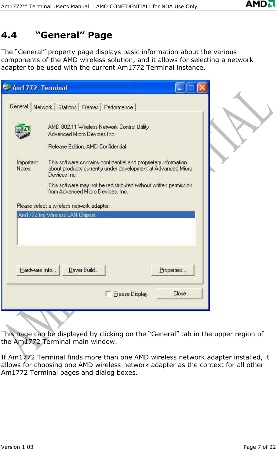
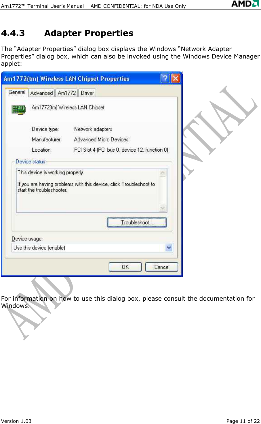
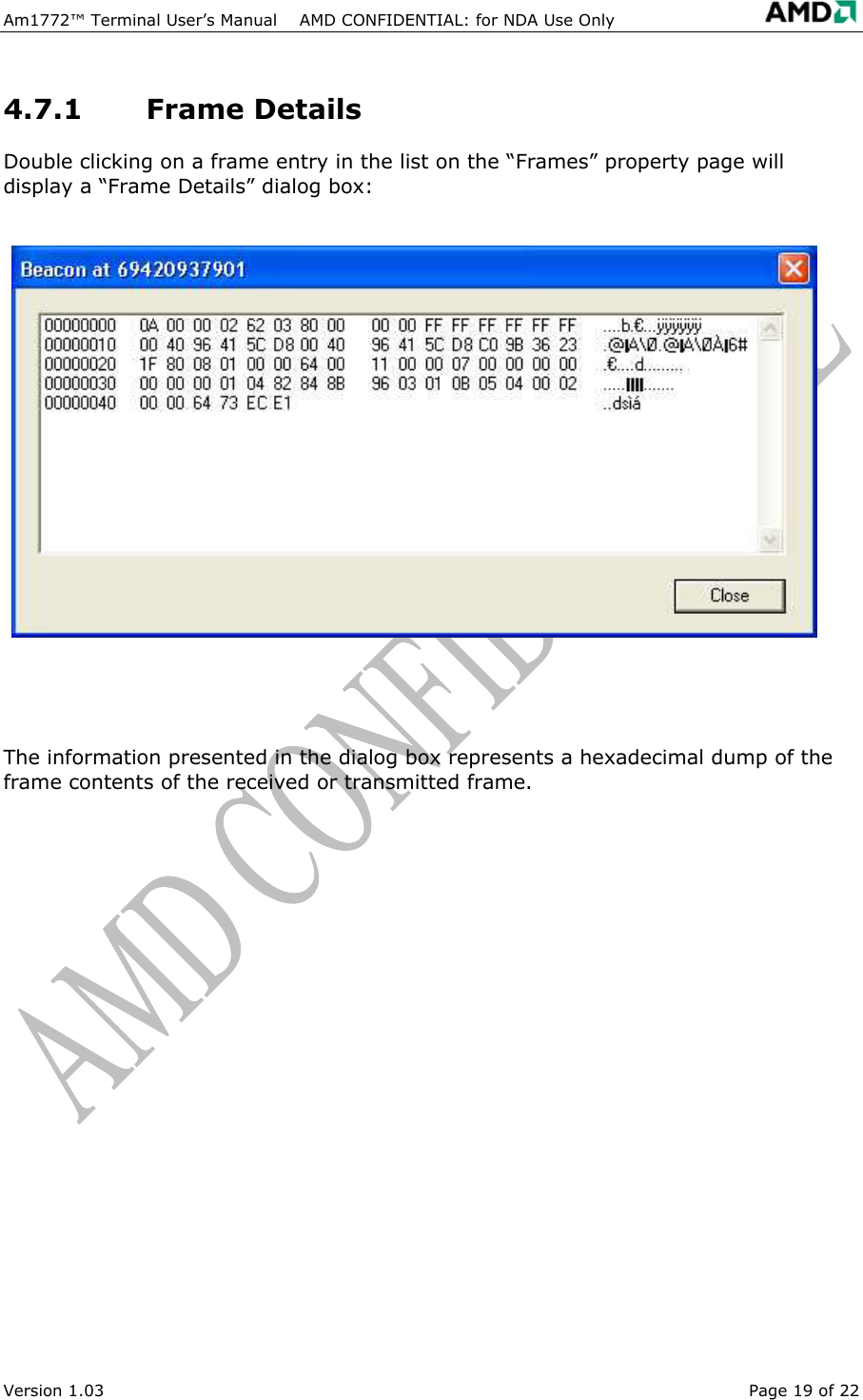
![Specification No. Item Condition Min. Typ. Max.Test Method/Condition 1. General specification 1-1. Standard IEEE 802.11b 1-2. Frequency Band(MHz) 2400 2483.5 1-3. No. of Selectable Channels 11 Channels (US, Canada) 13 Channels (Europe) 14 Channels (Japan) 1-4. Channel Spacing (MHz) 5 1-5. Modulation Technique DSSS (CCK, DQPSK, DBPSK) 1-6. Spreading 11-chip Barker Sequence 1-7. Media Access Protocol CSMA/CA(collision Avoidance) with ACK 1-8. Interface PCMCIA Type II 3.3V 1-9. Dimensions 115.0 mm x 54.0 mm x 6.5 mm 1-10. LED Indicators Link, Power 1-11. Antenna Connector On board patch 2. Standard Test Condition 2-1. Supply voltage(V) 3.3 3. Electrical Specification Temperature Range:0 ~ 55℃ Humidity:95 % (Non-condensing) 150 Receiver Mode 3-1. Power Consumption (mA) @+3.3V 260 Transmit Mode -82 -84 @ 11 Msps -87 @ 5.5 Msps -90 @ 2 Msps 3-2 Receive Sensitivity (dBm)[FER < 8%] -92 @ 1 Msps 3-3. Average Output Power (dBm) 11dBm 12dBm @29.5dB difference between the signal level at center frequency and higher first side lobe 3-4 Frequency Accuracy(ppm) - 25 + 25 Page : 2/3](https://usermanual.wiki/Prime-Electronics-and-Satellitics/WP288P/User-Guide-320415-Page-25.png)