Primex Wireless PA RF Amplifier User Manual
Primex Wireless, Inc. RF Amplifier
Users Manual

CommandPoint 72XR5 and 72XR30
User Guide
Complete Coverage for every type of facility
SCHOOLS
HEALTHCARE
GOVERNMENT
INDUSTRIAL
CORPORATE


CommandPoint 72XR5 and 72XR30 System Manual
CONTENTS
Product Description . . . . . . . . . . . . . . . . . . . . . . . . . . . . . . . . . . . . . . . . . . . . . . . . . . . . . . . . . . . . . . . . . . . . . . . . . . . 4
FCC and IC information . . . . . . . . . . . . . . . . . . . . . . . . . . . . . . . . . . . . . . . . . . . . . . . . . . . . . . . . . . . . . . . . . . . . . . . . . 4
Compliance Statements . . . . . . . . . . . . . . . . . . . . . . . . . . . . . . . . . . . . . . . . . . . . . . . . . . . . . . . . . . . . . . . . . . . . . 4
RF Exposure . . . . . . . . . . . . . . . . . . . . . . . . . . . . . . . . . . . . . . . . . . . . . . . . . . . . . . . . . . . . . . . . . . . . . . . . . . . . . . 4
License Requirements . . . . . . . . . . . . . . . . . . . . . . . . . . . . . . . . . . . . . . . . . . . . . . . . . . . . . . . . . . . . . . . . . . . . . . 5
System Components . . . . . . . . . . . . . . . . . . . . . . . . . . . . . . . . . . . . . . . . . . . . . . . . . . . . . . . . . . . . . . . . . . . . . . . . . . 5
Transmitter . . . . . . . . . . . . . . . . . . . . . . . . . . . . . . . . . . . . . . . . . . . . . . . . . . . . . . . . . . . . . . . . . . . . . . . . . . . . . . . 5
High Power Amplifier. . . . . . . . . . . . . . . . . . . . . . . . . . . . . . . . . . . . . . . . . . . . . . . . . . . . . . . . . . . . . . . . . . . . . . . . 5
GPS Receiver . . . . . . . . . . . . . . . . . . . . . . . . . . . . . . . . . . . . . . . . . . . . . . . . . . . . . . . . . . . . . . . . . . . . . . . . . . . . . 5
GPS/Transmitter Extension Cable . . . . . . . . . . . . . . . . . . . . . . . . . . . . . . . . . . . . . . . . . . . . . . . . . . . . . . . . . . . . . 5
Lightning Arrestor . . . . . . . . . . . . . . . . . . . . . . . . . . . . . . . . . . . . . . . . . . . . . . . . . . . . . . . . . . . . . . . . . . . . . . . . . . 5
Ground Plane Omnidirectional Antenna . . . . . . . . . . . . . . . . . . . . . . . . . . . . . . . . . . . . . . . . . . . . . . . . . . . . . . . . . 5
72XR5 and 72XR30 Specifications . . . . . . . . . . . . . . . . . . . . . . . . . . . . . . . . . . . . . . . . . . . . . . . . . . . . . . . . . . . . . . . 6
System . . . . . . . . . . . . . . . . . . . . . . . . . . . . . . . . . . . . . . . . . . . . . . . . . . . . . . . . . . . . . . . . . . . . . . . . . . . . . . . . . . 6
Amplifier . . . . . . . . . . . . . . . . . . . . . . . . . . . . . . . . . . . . . . . . . . . . . . . . . . . . . . . . . . . . . . . . . . . . . . . . . . . . . . . . . 6
Ground Plane Antenna . . . . . . . . . . . . . . . . . . . . . . . . . . . . . . . . . . . . . . . . . . . . . . . . . . . . . . . . . . . . . . . . . . . . . . 6
Safety Precautions . . . . . . . . . . . . . . . . . . . . . . . . . . . . . . . . . . . . . . . . . . . . . . . . . . . . . . . . . . . . . . . . . . . . . . . . . . . . 6
Equipment Precautions . . . . . . . . . . . . . . . . . . . . . . . . . . . . . . . . . . . . . . . . . . . . . . . . . . . . . . . . . . . . . . . . . . . . . . . . 7
Transmitter Display. . . . . . . . . . . . . . . . . . . . . . . . . . . . . . . . . . . . . . . . . . . . . . . . . . . . . . . . . . . . . . . . . . . . . . . . . . . . 7
Time. . . . . . . . . . . . . . . . . . . . . . . . . . . . . . . . . . . . . . . . . . . . . . . . . . . . . . . . . . . . . . . . . . . . . . . . . . . . . . . . . . . . . . . 7
Daylight Saving Time. . . . . . . . . . . . . . . . . . . . . . . . . . . . . . . . . . . . . . . . . . . . . . . . . . . . . . . . . . . . . . . . . . . . . . . . . . 7
GPS Communication . . . . . . . . . . . . . . . . . . . . . . . . . . . . . . . . . . . . . . . . . . . . . . . . . . . . . . . . . . . . . . . . . . . . . . . . . . 7
Day/Date . . . . . . . . . . . . . . . . . . . . . . . . . . . . . . . . . . . . . . . . . . . . . . . . . . . . . . . . . . . . . . . . . . . . . . . . . . . . . . . . . . . 7
Channel Number . . . . . . . . . . . . . . . . . . . . . . . . . . . . . . . . . . . . . . . . . . . . . . . . . . . . . . . . . . . . . . . . . . . . . . . . . . . . . 7
Red LED . . . . . . . . . . . . . . . . . . . . . . . . . . . . . . . . . . . . . . . . . . . . . . . . . . . . . . . . . . . . . . . . . . . . . . . . . . . . . . . . . . . 7
72XR5 and 72XR30 Antenna Setup and Mounting. . . . . . . . . . . . . . . . . . . . . . . . . . . . . . . . . . . . . . . . . . . . . . . . . . . 8
System Operation . . . . . . . . . . . . . . . . . . . . . . . . . . . . . . . . . . . . . . . . . . . . . . . . . . . . . . . . . . . . . . . . . . . . . . . . . . . . . 8
Basic Operation of the System . . . . . . . . . . . . . . . . . . . . . . . . . . . . . . . . . . . . . . . . . . . . . . . . . . . . . . . . . . . . . . . . . . 8
Daylight Saving Time. . . . . . . . . . . . . . . . . . . . . . . . . . . . . . . . . . . . . . . . . . . . . . . . . . . . . . . . . . . . . . . . . . . . . . . . . . 9
Time Zone . . . . . . . . . . . . . . . . . . . . . . . . . . . . . . . . . . . . . . . . . . . . . . . . . . . . . . . . . . . . . . . . . . . . . . . . . . . . . . . . . . 9
12-Hour or 24-Hour Time. . . . . . . . . . . . . . . . . . . . . . . . . . . . . . . . . . . . . . . . . . . . . . . . . . . . . . . . . . . . . . . . . . . . . . . 9
Continuing Synchronization. . . . . . . . . . . . . . . . . . . . . . . . . . . . . . . . . . . . . . . . . . . . . . . . . . . . . . . . . . . . . . . . . . . . . 9
Power Failure. . . . . . . . . . . . . . . . . . . . . . . . . . . . . . . . . . . . . . . . . . . . . . . . . . . . . . . . . . . . . . . . . . . . . . . . . . . . . . . . 9
Troubleshooting . . . . . . . . . . . . . . . . . . . . . . . . . . . . . . . . . . . . . . . . . . . . . . . . . . . . . . . . . . . . . . . . . . . . . . . . . . . . . 10
Interference . . . . . . . . . . . . . . . . . . . . . . . . . . . . . . . . . . . . . . . . . . . . . . . . . . . . . . . . . . . . . . . . . . . . . . . . . . . . . . . . 10
Potential Lighting Strike. . . . . . . . . . . . . . . . . . . . . . . . . . . . . . . . . . . . . . . . . . . . . . . . . . . . . . . . . . . . . . . . . . . . . . . 10
Transmitter Problems. . . . . . . . . . . . . . . . . . . . . . . . . . . . . . . . . . . . . . . . . . . . . . . . . . . . . . . . . . . . . . . . . . . . . . . . . 10
Display Does Not Light Up . . . . . . . . . . . . . . . . . . . . . . . . . . . . . . . . . . . . . . . . . . . . . . . . . . . . . . . . . . . . . . . . . . . . 10
Display Lights Up, but is Blank or Very Faint . . . . . . . . . . . . . . . . . . . . . . . . . . . . . . . . . . . . . . . . . . . . . . . . . . . . . . 10
Signal Reception Problems . . . . . . . . . . . . . . . . . . . . . . . . . . . . . . . . . . . . . . . . . . . . . . . . . . . . . . . . . . . . . . . . . . . . 10
Displayed Time/Date is Incorrect. . . . . . . . . . . . . . . . . . . . . . . . . . . . . . . . . . . . . . . . . . . . . . . . . . . . . . . . . . . . . . . . 11
Red LED flashing. . . . . . . . . . . . . . . . . . . . . . . . . . . . . . . . . . . . . . . . . . . . . . . . . . . . . . . . . . . . . . . . . . . . . . . . . . . . 11
Product Installation/Troubleshooting . . . . . . . . . . . . . . . . . . . . . . . . . . . . . . . . . . . . . . . . . . . . . . . . . . . . . . . . . . . . . 12
CommandPoint 72XR5 and 72XR30 System Manual
4
Product Description
The CommandPoint 72XR System automatically synchronizes clocks through a wireless radio signal.
The GPS satellites transmit time information to the GPS receiver that sets the Transmitter’s internal clock
to the precise GPS time. The Transmitter rebroadcasts that time via a radio signal to system clocks and
components within the range of the system.
As a result, all clocks, bells, and timers in the wireless system are precisely synchronized to each other and
to the U.S. Government’s official NIST time standard, Coordinated Universal Time (UTC). All components of
the CommandPoint 72XR System are routinely updated to ensure both precision and synchronization.
Currently 5W and 30W versions of the CommandPoint 72XR System are available. The 72XR5 and 72XR30
systems include an externally mounted antenna and an RF power amplifier that increases the output power,
allowing it to transmit a greater distance.
Federal Communications Commission (FCC) and Industry Canada (IC)
Information
Compliance Statements
This device complies with Part 15 and Part 90 of the FCC rules. It also complies with the RSS-119 of
Industry Canada. Operation is subject to the following two conditions:
1. This device may not cause harmful interference, and
2. This device must accept any interference received, including interference that may cause
undesirable operation.
Canada IC: 4256A-FM72 (TX/RX/LED)
The term "lC:" before the certification/registration number signifies only that the Industry Canada technical
specifications were met.
Warning: Changes or modifications to any part of the Primex Wireless System components not
expressly approved by Primex Wireless could void the user’s FCC/IC authority to
operate the equipment.
Radio Frequency (RF) Exposure
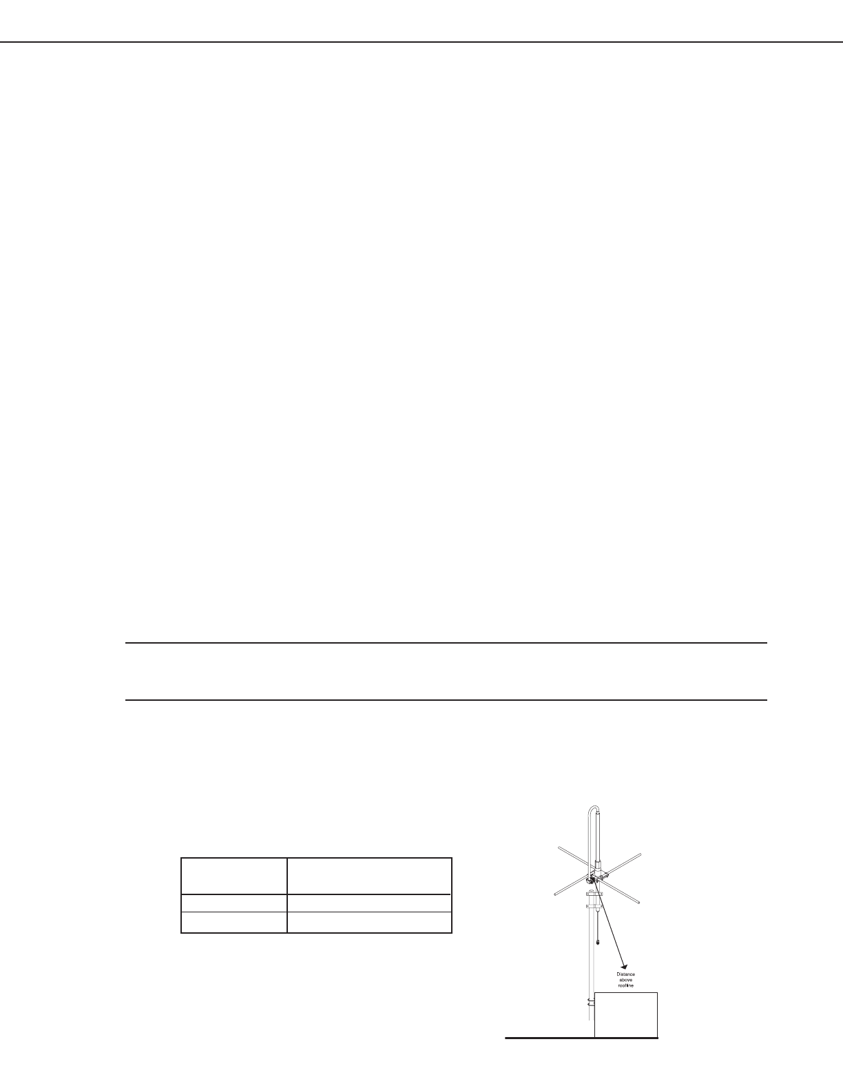
To comply with FCC OET65 and Industry Canada RF exposure requirements, the antenna is only to be used
or installed in locations where the following antenna separation guidelines exist when the transmitter is in
operation. This table is for direct line of sight only. See figure A.
Power Level Distance above roofline
(W)
72XR5 6.8’ (2.07m)
72XR30 9.3’ (2.83m)
Figure A
CommandPoint 72XR5 and 72XR30 System Manual
5
License Requirements
Operation of the System requires a license, which must be obtained prior to operation. FCC licenses must be
renewed every 10 years, and the IC licenses must be renewed annually. As a service, Primex Wireless will
file the license application for you. If you chose not to have Primex Wireless file, you are required to complete
a waiver form with Primex Wireless, file the required application, and receive a valid license from the FCC/IC
prior to use. Primex Wireless will need to be notified with the call sign given by the FCC/IC. If you have any
questions or need assistance, please contact Primex Wireless at 1-800-537-0464.
System Components and Specifications
Transmitter
The Transmitter receives the time from the GPS Receiver and synchronizes to the precise GPS time.
The Transmitter continuously broadcasts its GPS synchronized time to the system clocks, bells, and
tones. The Transmitter operates on channels with 20kHz bandwidths between the frequencies of 72-76
MHz and is preset to one of the channels licensed by the FCC/IC to minimize interference on these
frequencies and channels.
High Power Amplifier
The 72XR5 and 72XR30 systems increase the output power of the base Transmitter by utilizing a high
power amplifier. The amplifier is housed in an industrial style enclosure for safety reasons.
GPS Receiver
The Global Positioning System (GPS) Receiver has a sensitive antenna that receives the precise time
(UTC) from the GPS satellite transmission. The GPS receiver must have an unobstructed "view of the
sky" to maximize the GPS receiver’s ability to receive signal 24-hours per day.
GPS/Transmitter Extension Cable
A specially designed low-resistance data cable is available upon request to extend the distance between
the GPS receiver and the Transmitter. The GPS receiver continuously sends the precise time through the
cable to the Transmitter.
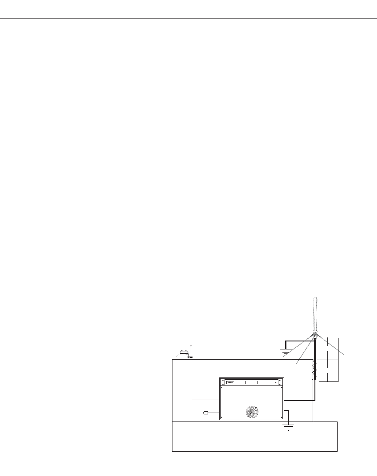
Lightning Arrestor
The lightning arrestor is housed inside
the enclosure and helps protect the
transmitter and amplifier from lightning
damage during severe weather.
However, we cannot guarantee that all
damage will be prevented even with the
lighting arrestor installed.
Ground Plane Omnidirectional
Antenna
This antenna is a heavy duty, light
weight ground plane antenna designed
to be mounted outdoors.
10:10:35AM
Building
Penthouse
GPS
10-200’
Shield
CAT5 Cable
To 120/ac Supply
100’ Cable
Ground
Ground
A
n
t
e
n
n
a
3’ (0.9m)
7’ (2.13m)
10’ (3.05
m
Figure B - Typical system setup (Not to scale)

CommandPoint 72XR5 and 72XR30 System Manual
6
72XR5 and 72XR30 Specifications:
System:
• Frequency Range: 72-76 MHz
• Enclosure Dimensions: 20.8”W x 17.6”H x 21.4”D (.53mW x 45mH x .54mD)
• Approx. Weight: 75 lbs.
• Power Supply:
- Input: 120 VAC, 50/60 Hz, 72XR5 <5Amps, 72XR30 <30Amps
• Operating Temperature Range: 32°-122°F (0°-50°C)
• Cabling: 100’ between amplifier and antenna
• System Impedance: 50 Ohms
• FCC Part 90 Accepted
• IC R55-119 Accepted
• Oversized heat sink for adequate cooling
Amplifier:
• Bandwidth: 20 MHz maximum
• Gain Flatness: +/- 1dB at 72-76 MHz
• Output Power at Antenna:
- 72XR5: 5W
- 72XR30: 30W
• Harmonics (-dBc): See Part 90 Requirements
• Spurious: -60 dBc
• VSWR (maximum): 1:5
• Impedance: 50 Ohms
Ground Plane Antenna:
• Polarization: Vertical
• Connector: N-male
• Gain: Unity
• VSWR: 1:1.5
• Lightning Protection: Direct Ground
• Pole or Wall Mountable
• Dimensions: 62”L x 64”W (1.6mL x 2.64mW x 1.6mW)
Safety Precautions
Warning: The CommandPoint Transmitter is designed for indoor use only, and is not weather
protected. Operating the system outdoors during adverse weather conditions is an
electrical hazard, may damage the equipment, and nullifies the warranty.
Standard acceptance procedures must be followed prior to operating this equipment
in the proximity of life support systems.
Do NOT touch the antenna while the transmitter is operating as it could result in a
skin burn or other injuries, see Figure A.
CommandPoint 72XR5 and 72XR30 System Manual
7
Equipment Precautions
Warning: Primex Wireless disclaims any liability or responsibility for the results of improper or
unsafe installation practices.
Never operate the Transmitter without the antenna being properly connected to
the Transmitter. Operating the Transmitter without an antenna can destroy the
Transmitter’s power output and poses a safety risk.
Note: Equipment must be installed by a Primex Wireless certified installer.
Transmitter Display
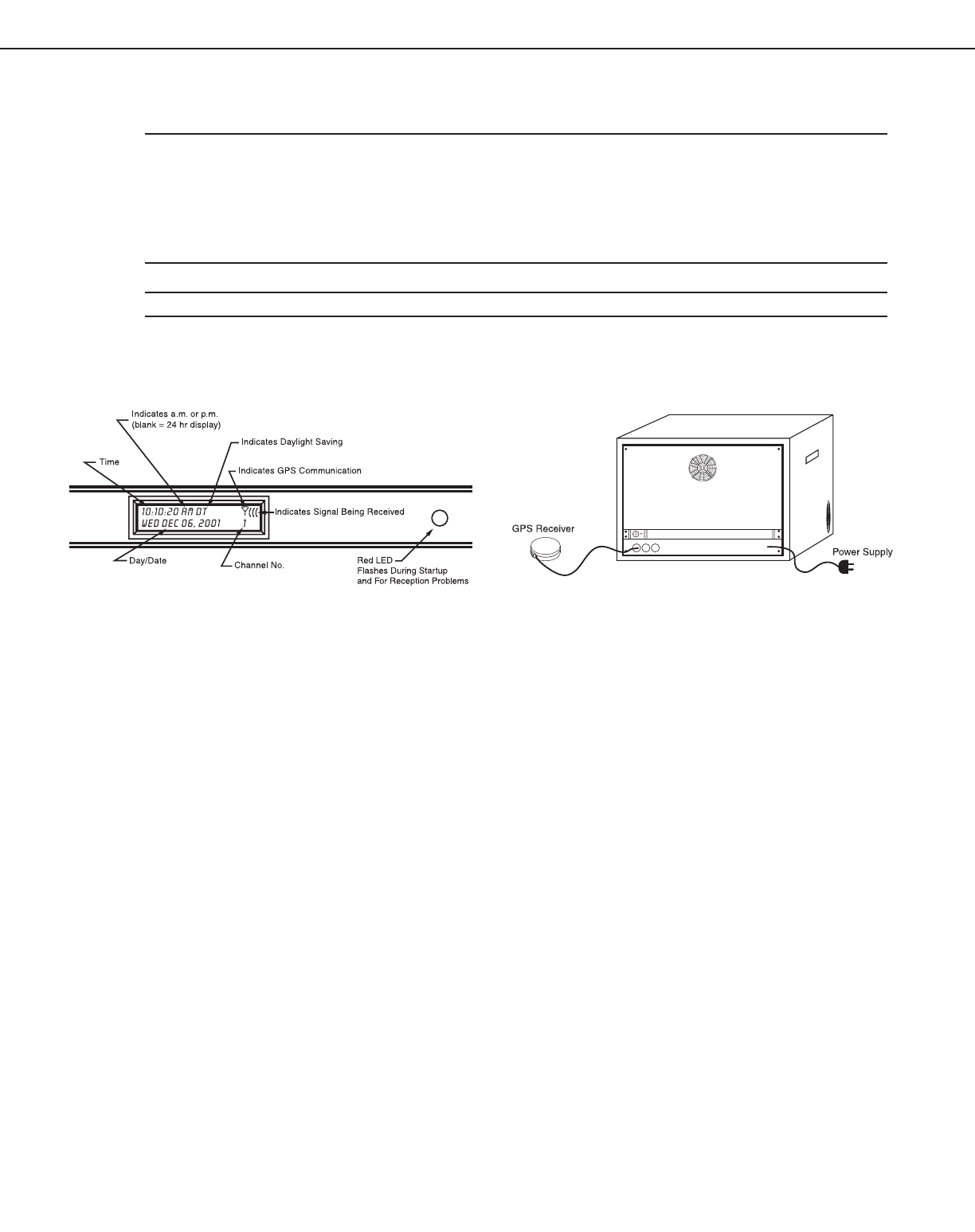
Figure C - Front of Transmitter Figure D -Back View of the Transmitter
The Transmitter has a lighted front display that shows important information.
Time (1)
Displays the precise time received from the GPS receiver. If AM or PM is on the display, then the 12-hour
option is selected. If neither AM nor PM is on the display, then the 24-hour option is selected.
Daylight Saving Time (2)
The letters "DT" (Daylight Saving Time) or "ST" (Standard Time) will be displayed when adjustment for
Daylight Saving Time is active. If neither "DT" nor "ST" is displayed, then switch #3 is in the down position
and the Transmitter will not adjust for Daylight Saving Time.
GPS Communication (3)
The GPS communication indicator (see Figure B) will appear when the Transmitter is communicating with
the GPS Receiver. The parentheses indicate the time signal is being received.
Day/Date (4)
Displays the day and date received from the GPS satellites.
Channel Number (5)
Displays the channel number (1-16) that the Transmitter is set to. If the Transmitter’s output is disabled,
SB will be shown on the display to indicate standby.
Red LED (6)
The red LED (Light Emitting Diode) is located on the right side of the front panel of the Transmitter. The
LED flashes on initial setup until a GPS time signal is received or when a severe GPS reception problem
has occurred and no time data has been received from the GPS Receiver in 48 hours. See the
Troubleshooting section of this manual for more information.
Time
(1)
(1)
(2)
(3)
(3)
(4) (5) (6)

CommandPoint 72XR5 and 72XR30 System Manual
8
72XR5 / 72XR30 Antenna Setup and Mounting
Warning: The installation, maintenance, or removal of an antenna
should only be performed by a Primex Wireless certified
installer.
System Operation
The following assumes that the Transmitter, antenna and
GPS receiver have been properly set up as previously described.
Basic Operation of the System
When power is first applied to the Transmitter, the front display will light up and show important
information. The red LED light will flash until the Transmitter receives a valid time signal from the GPS
Receiver.
The display will initially show the time as 12:00:00 and will note the software version and call sign.
The Transmitter then checks the position of the switches on the rear of the Transmitter and stores
their settings in memory. Next the Transmitter sends information to the GPS Receiver and waits for
time information from the GPS Receiver.
The GPS Communication indicator (see Figure C) will appear when the Transmitter is receiving a signal
from the satellite through the GPS Receiver. If the symbol is not displayed, see Troubleshooting.
The time on the display will increment once each second until the GPS Receiver sends the transmitter a
valid time. The GPS Receiver needs to “see” 3 satellites in the sky before it will send a time signal to the
transmitter. This may take up to 15 minutes for a GPS Receiver that has a 360° view of the sky. The
length of time is dependent on the location, weather conditions, time of day, etc. In areas where the
receiver does not have a full view of the sky, due to wall or window installations, building “shadows”, etc.,
this may take up to several hours.
Note: The Transmitter does not transmit time data until it has received valid time information
from the GPS Receiver.
Once the Transmitter receives the GPS Receiver time signal, the Transmitter sets its internal clock to
that time and will display the correct time and date. The Transmitter then begins transmission of its
internal time once every second. The transmission signal is at approximately 72 MHz. The GPS Receiver
is continuously monitored and the Transmitter updates its internal clock with the time data it receives.
The number to the right side of the display is the channel number to which the Transmitter will be
broadcasting the time signal. On power up, the transmitter will broadcast continuously for 8 hours. At
this time, the channel number will change to SB (Standby). After the 8 hours, the system will then only
transmit from 39 minutes after the hour to 6 minutes past the next hour.
Warning: The channel number is fixed and must be the same as the channel number specified
on your FCC/IC license. If this is not the case, you must immediately call Primex
Wireless Technical Support at 1-800-404-8112.
Note: If the Transmitter receives no valid time data from the GPS Receiver for 48 hours, then
the red LED on the right side of the front panel will flash.
Figure E - Antenna Setup

CommandPoint 72XR5 and 72XR30 System Manual
Daylight Saving Time
The Transmitter is pre-programmed to automatically make adjustments for Daylight Saving Time. The
letters "DT" (Daylight Saving Time) or "ST" (Standard Time) will be displayed when adjustment for
Daylight Saving Time is active (switch #3 in the up position). If neither "DT" nor "ST" is displayed, then
switch #3 is in the down position and the Transmitter will not adjust for Daylight Saving Time.
The adjustment to Daylight Saving Time and back to Standard Time take place at three seconds after
2:01 AM on the day of change.
Note: The GPS signal does not encode information about Daylight Saving Time. In the spring
when the Transmitter changes to Daylight Saving Time, the system clocks will adjust by
advancing at 8 times their normal speed to make the adjustment and then return to
normal operation. In the fall when the Transmitter returns to Standard Time, the system
clocks will make the time adjustment and then return to normal operation.
Time Zone
The time zone of your location is not shown on the display. However, when the Transmitter has received a
valid time from the GPS Receiver, the correct time zone can be checked by verifying that the correct hour
is displayed. The Transmitter can be set for all 24 time zones around the world.
12-Hour or 24-Hour Time
The 12/24-Hour option only affects the Transmitter’s LCD display. If AM or PM is on the display, then the
12-hour option is selected with switch #4. If neither AM nor PM is on the display, then the 24-hour option
is selected. Analog System Clocks are 12-hour clocks. LED Digital System Clocks have a selectable
jumper option to display either 12-hour or 24-hour time regardless of the Transmitter’s 12/24 option
setting.
Continuing Synchronization
The status of the GPS Receiver is indicated by the GPS Communication indicator. When the "Y"-like
symbol is displayed, the GPS Receiver is connected to the Transmitter and there is proper
communication between the GPS Receiver and the Transmitter. When the Transmitter is receiving
valid time data from the GPS Receiver, the three parentheses will sequence in a motion pattern. If
these symbols are not displayed, see Troubleshooting.
Power Failure
The System has a fail-safe design. If the failure of a system component or power loss to a component
occurs, all down stream components continue normal operations using their own internal time base.
If after a specified period of time, communication has not been restored, a visual indicator that notifies
the user of a loss of communication appears and remains until communication is restored. Examples:
Red flashing LED on the Transmitter; flashing colons on LED digital clocks; stepping of second hand on
analog clocks.
IMPORTANT
In the event of a facility wide power outage, upon power restoration the transmitter will broadcast
continuously for 8 hours, synchronizing all the Primex Wireless products throughout your facility. If the
power failure is local to a single clock or a few clocks, see the the Troubleshooting section.
9

CommandPoint 72XR5 and 72XR30 System Manual
10
Troubleshooting
Interference
If interference is noticed on televisions, radios or other wireless devices when the system is powered up,
a scheduled transmit option is available. This will allow the transmitter to broadcast only at predetermined
times, minimizing the possibility for interference. Contact Primex Wireless technical support
at 1-800-404-8112 for more information.
Potential Lightning Strike
If you suspect your system has been struck by lightning contact Primex Wireless Technical Support
at 1-800-404-8112.
Transmitter Problems
The first step in troubleshooting the Transmitter is to reset the GPS Receiver. If the Transmitter fails to
receive a GPS signal and is set to time within 15 minutes, please reset the System.
Note: To reset the GPS Receiver, cycle power to the system.
Power glitches, line spikes, power interruptions, static discharge or other voltage fluctuations can cause
loss of communication with the GPS Receiver if the disruption occurs during the initial setup communica-
tion between the Transmitter and the GPS.
Note: The time of day, view of the sky, weather, solar flares and local interference also influence
signal reception and can cause temporary loss of the GPS signal. If reception problems
persist, see Signal Reception Problems.
Display Does Not Light Up
If the display does not light up, check the power supply connection to the Transmitter and to the 120 VAC
outlets. If this does not correct the problem, either the power supply or the Transmitter may be defective.
Call Primex Technical Support at 1-800-404-8112.
Display Lights Up, But Is Blank or Very Faint
Call Primex Technical Support at 1-800-404-8112. The Transmitter may need to be replaced.
Signal Reception Problems
1. Verify that the GPS Receiver is properly connected to the Transmitter.
2. Verify that the GPS Receiver is properly mounted on a non-Low-E glass window or on a rooftop or
pole outside with a clear view of the sky.
3. Check to assure that the GPS Communication indicator is showing on the display (looks like a "Y"
with a line over it). If this symbol is displayed, then the Transmitter is communicating with the GPS
Receiver.
a. If the GPS Communication indicator is not being displayed, then the Transmitter, GPS Receiver,
or the connection between Transmitter and GPS Receiver is defective. Check GPS cable con-
nections.

CommandPoint 72XR5 and 72XR30 System Manual
11
Note: The use of unshielded or standard shielded cables to extend the distance between the
GPS Receiver and the Transmitter beyond 50 feet can cause this failure mode. A special
shielded cable with low resistance on the voltage supply line is required for distances
over 50 feet. The maximum distance using the special cable is 200 feet. If cable
connections are good, replace the GPS Receiver.
b. If the GPS Communication indicator is displayed but the parentheses are not flashing, then the
problem is with the GPS Receiver or with its signal reception.
– Check to make sure that the GPS Receiver has a clear view of the sky and that its view is
not obstructed.
Note: Double pane Low-E glass windows are coated with a transparent metal layer that reflects
infrared heat rays; this will also reflect the GPS signal. The GPS Receiver will not receive
the signal through Low-E windows.
– Local interference can affect GPS reception. Try moving the location of the GPS receiver to
improve reception.
– Weather conditions, solar flares, time of day, and exact satellite position may also effect
signal reception; however, these conditions are normally of a short duration.
Note: When certain types of electronic light ballasts become defective they may radiate
broadband noise, which can interfere with wireless devices. While interference issues
are unlikely with the Primex Wireless Clock System, high levels of noise present in
the 72-76MHz range could potentially cause clocks which are located far from the
transmitter and also within the close proximity of these ballasts to not receive a signal.
Very limited instances have occurred in the past, which has only been found to happen
when ballasts become defective.
Displayed Time/Date is Incorrect
1. If the minutes and seconds are correct, but the hours are off or the day is off, then switches #2, #3,
or Rotary Switch B are in the wrong position. Correct switch settings. See Switch Settings for
proper settings.
2. Other than for the above reason, or the loss of the GPS signal, the Transmitter, whose time is
controlled by a GPS signal, should never display the wrong time or date. If such an event occurs,
please contact Primex Wireless Technical Support at 1-800-404-8112.
Red LED is Flashing
The Red LED flashes when the unit has not received an updated time signal for 48 hours. It will also flash
during initial setup, but will go out once a valid GPS time has been received. Call Primex Wireless Tech
Support at 1-800-404-8112.

CommandPoint 72XR5 and 72XR30 System Manual
12
Product Installation/Troubleshooting
As was previously stated, this transmitter broadcasts a signal from 39 minutes after the hour to 6 minutes
after the hour (except through 11:39pm- 12:06am). After this time, the transmitter’s output will go into standby
and the display will indicate SB.
Note: In the event of a facility wide power outage the transmitter will broadcast for 8 hours upon
the restoration of power. This will synchronize all products.
In the event that the power to a transmitter is shut off and turned back on, the transmitter
will broadcast continuously for 8 hours. Power cycling the transmitter can be used to
set/reset products.
The text below summarizes how each product reacts to timed operation.
Manual Setting Battery Operated Clocks
• These clocks can be identified as analog clocks with a grey set wheel located on the back side.
• While using the timed transmit schedule, the battery operated clocks will update at 2, 6, and 10 am/pm.
• If installing clocks after the initial 8 hour transmission, there are 2 options
1. Install clocks between 39 minutes past the hour and 6 minutes after the next hour. They will set right
away.
2. Cycle power to the transmitter. It will then transmit for 8 hours and clocks will set immediately on
power up.
• If the clock’s batteries expire and are replaced when the transmitter is not broadcasting, the clock will
not reset until the transmitter is power cycled.
• If 7 days pass without the clock receiving a signal from the transmitter, it will begin double stepping
(taking two steps every two seconds) to alert the user of a signal reception problem
Automatic Setting Battery Operated Clocks
• These clocks can be identified as analog clocks that do not have grey set wheel
• While using the timed transmit schedule, the battery operated clocks will update at 2, 6, and 10 am/pm.
• If installing clocks after the initial 8 hour transmission, there are 2 options
1. Install clocks between 39 minutes past the hour and 6 minutes after the next hour. They will set right
away.
2. Cycle power to the transmitter. It will then transmit for 8 hours and clocks will set immediately on
power up.
• If the clock’s batteries expire and are replaced when the transmitter is not broadcasting, it will not reset
until the transmitter is power cycled.
• If 4 days pass without the clock receiving a signal from the transmitter, it will begin five stepping (taking
five steps every five seconds) to alert the user of a signal reception problem.

CommandPoint 72XR5 and 72XR30 System Manual
13
AC Powered Analog Clocks
• While using the timed transmit schedule, the clocks will update at 2, 6, and 10 am/pm. If a signal is not
received at a specific update time, the clock will continue to search for a signal until it receives one.
• If installing clocks after the initial 8 hour transmission, there are 3 options
1. Install clocks between 39 minutes past the hour and 6 minutes after the next hour. They will set right
away.
2. Install the clocks any time of the day. They will not set until 39 minutes after the hour.
3. Cycle power to the transmitter. It will then transmit for 8 hours and clocks will set immediately on
power up.
• If 4 days pass without the clock receiving a signal from the transmitter, it will begin five stepping (taking
five steps every five seconds) to alert the user of a signal reception problem.
Digital LED Clocks
• While using the timed transmit schedule, the LED clocks will update at 39, 45, 55, and 05 minutes past
the hour.
• If installing clocks after the initial 8 hour transmission, there are 3 options
1. Install clocks between 39 minutes past the hour and 6 minutes after the next hour. They will set right
away.
2. Install the clocks any time of the day. They will display dashes until they receive a signal from the
transmitter 39 minutes after the hour.
3. Cycle power to the transmitter. It will then transmit for 8 hours and clocks will update immediately on
power up.
• If the clock loses power when the transmitter is in standby and not broadcasting, it will show dashes
until 39 minutes after the hour.
• If an LED clock has been synchronized and has not received a signal from the transmitter in 72 hours,
the colons will flash.
Receiver Switch (Repeater)
• While using the timed transmit schedule, the receiver switch will update between 40 and 56 minutes
past the hour. The actual update time varies depending on what channel number it is receiving a signal
on.
• If installing a receiver switch after the initial 8 hour transmission, there are 3 options
1. Install the receiver switch between 39 minutes past the hour and 6 minutes after the next hour. It will
set right away.
2. Install the receiver switch at any time of the day, it will disable the output of the satellite transmitter
and the green LED will remain solid until 39 minutes after the hour. At that time, the LED will begin
flashing and the transmitter connected to it will begin broadcasting.
3. Cycle power to the transmitter. It will then transmit for 8 hours and the receiver switch will update
immediately on power up.
• If a receiver switch loses power when the transmitter is not broadcasting, it will disable the output of the
satellite transmitter and the green LED will remain solid until 39 minutes after the hour. At that time, the
LED will begin flashing and the transmitter connected to it will begin broadcasting.
• If an receiver switch has been synchronized and did not receive a signal from the transmitter the
previous hour, the green LED will go solid. If it has not received a signal in 48 hours the red LED on
the transmitter it is connected to will begin to flash.

CommandPoint 72XR5 and 72XR30 System Manual
14
Wireless Tone Generator
• While using the timed transmit schedule, the wireless tone generator will update between 39 and 6
minutes past the hour. The green LED on the wireless tone generator will flash during this time
indicating that it is receiving a signal.
• If installing a wireless tone generator after the initial 8 hour transmission, there are 2 options
1. Install the wireless tone generator between 39 minutes past the hour and 6 minutes after the next
hour. It will update its time right away and begin updating its schedule information.
2. Cycle power to the transmitter. It will then transmit for 8 hours and the wireless tone generator will
update both its time and schedule information immediately on power up.
• If the wireless tone generator loses power when the transmitter is not broadcasting, the LED will go solid
until 39 minutes after the hour. At that time, the LED will begin flashing and the time and event schedule
information will be updated.
• When a new event schedule is downloaded to a transmitter, it will broadcast continuously for 30 minutes
to update the time and schedule information in the wireless tone generator.
If you have any questions regarding products impacts of timed transmission please contact Technical Support
at 1-800-404-8112.

CommandPoint 72XR5 and 72XR30 System Manual
15

Primex Wireless, Inc. ©2006, Patents Pending. Printed in the USA. 140135 10/06/06
Primex Wireless, Inc. – Canada
Phone: 1-800-330-1459 Fax: 905-952-0134
Technical Support: 1-800-404-8112
Email: info@primexwireless.ca
Website: www.primexwireless.ca
Primex Wireless, Inc. – US
Phone: 1-800-537-0464 Fax: 262-248-0061
Technical Support: 1-800-404-8112
Email: info@primexwireless.com
Website: www.primexwireless.com