Primex Wireless SNSE Emergency Lighting Controller User Manual
Primex Wireless, Inc. Emergency Lighting Controller
User Manual

1
Emergency Light Monitoring
Installation and User Guide
December 3, 2010
Part Number: SNSDOC-003

Installation and User Guide Emergency Light Monitoring
2
Contents
Introduction.............................................................................................................................................3
Before You Begin....................................................................................................................................4
Scope of This Guide ...............................................................................................................................5
Reference Documentation .....................................................................................................................5
Electrical Systems Supported ...............................................................................................................6
Materials Required..................................................................................................................................6
Planning the Installation ........................................................................................................................8
New Fixture Installation Overview.........................................................................................................9
Retrofit Installation Overview ..............................................................................................................10
Emergency Light Controller.................................................................................................................11
Best Practices for Retrofitting an Emergency Light Fixture.............................................................13
Color Codes for AC/DC Power.............................................................................................................16
The ELC Emergency Light Fixture ......................................................................................................19
Installing the ELC Emergency Light Fixture ......................................................................................20
Configuring the Emergency Light Controller (ELC) ..........................................................................21
Using the AMP for Emergency Light Testing and Monitoring..........................................................23
Troubleshooting the Installation .........................................................................................................24

Emergency Light Monitoring Installation and User Guide
3
Introduction
The Emergency Light Monitoring Solution addresses the need to test battery operated emergency lights
and combination exit signs for compliance with NFPA 101 regulations. Periodic and annual tests can
be scheduled, performed, and monitored while all results are archived for future reference.
This solution provides the following features:
• Emergency Light monitoring via new fixtures or retrofit existing equipment
• Remote/automated testing and monitoring for NFPA 101 compliance
• Floor map display of Emergency Light location
• Periodic or annual performance reports
• Communication over Wi-Fi 802.11 b/g or Ethernet network interfaces
Notices
© Copyright 2011, Primex Wireless; all rights reserved.
SNS and AMP are trademarks of Primex Wireless, Inc.
Contact Primex Wireless
Web: http://www.primexwireless.com/
Email: support@primexwireless.com
United States Canada
Telephone: (800) 537-0464 (800) 330-1459
Hours: 7:00am - 5:00pm Central 7:00am - 5:00pm Central
Fax: (262) 248-0061 (905) 952-0134

Installation and User Guide Emergency Light Monitoring
4
Before You Begin
Please read this document thoroughly before performing any installation or service procedures.
Warning!
TO REDUCE THE RISK OF ELECTRIC SHOCK, DISCONNECT POWER SOURCE BEFORE
PERFORMING ANY INSTALLATION OR SERVICE ACTIVITIES!
PLEASE READ AND FOLLOW THE FOLLOWING SAFETY RECOMMENDATIONS:
• Installation and service procedure must be performed by qualified personnel
• Make sure all work performed is in accordance with the National Electrical Code and any other
local regulations.
• This product is intended to be used in INDOOR applications only.

Emergency Light Monitoring Installation and User Guide
5
Scope of This Guide
This guide supports the SNS Emergency Light Controller (ELC), a component of the overall Emergency
Light Monitoring solution. The ELC may be integrated with a customer’s existing emergency light
fixtures or alternatively be pre-integrated into a light fixture from Primex Wireless (ELC Integrated
Fixture).
Installation of the ELC requires the expertise of a qualified electrician for wiring and mounting as well as
a network technician for configuration of settings.
This user guide will focus on:
• ELC deployment into existing fixtures
• Installation of an ELC Integrated Fixture
• Network configuration of the ELC
Reference Documentation
During and after installation, please refer to the SNS Resource CD for complete SNS product
documentation.
Installation Task Document
Install/configure AMP software • SNS System Installation and
Network Admin Manual
• Application Management Platform
(AMP™) User Guide Version
Auto-configuration of ELC
Install new or retrofit Emergency Light fixture
with ELC integrated
Manual testing of ELC
• Emergency Light Monitoring
Installation and User Guide
Automated testing of ELC • SNS AMP User Guide for
Emergency Light Monitoring
• Application Management Platform
(AMP™) User Guide Version

Installation and User Guide Emergency Light Monitoring
6
Electrical Systems Supported
The Emergency Light Controller (ELC) and associated products are intended to be used with the
following input voltages:
• 120 VAC
• 220 VAC
• 277 VAC
Materials Required
You need the following materials to perform procedures described in this document.
1. Pliers (Needle Nose/Side Cutting)
2. Wire strippers and cutters
3. Screwdriver-Standard
4. Screwdriver-Phillips
5. Adjustable wrench
6. Electrical tape
7. Wire Connection set (various wire connectors)
8. Multi-meter
9. Drill
10. Knock-out Set

Emergency Light Monitoring Installation and User Guide
7
Compatible Light Fixture
Note: Make sure any Emergency Lighting fixture is compatible with the ELC both electrically and in
terms of space to accommodate wiring.
• Battery voltage between 4.5 VDC and 38 VDC
• Maximum current draw of 5 AMPS
• Fixture must use incandescent bulbs
• Adequate space for ELC shaft and associated wiring to complete installation

Installation and User Guide Emergency Light Monitoring
8
Planning the Installation
Planning the installation of Emergency Light installation must take into consideration several factors:
1. Installation of AMP software (covered in the “SNS System Install and Admin Manual”)
2. Configuration of Emergency Light Controllers (ELC)
3. Installation of new Emergency Light fixtures (if required)
4. Retrofitting of existing Emergency Light fixtures (if required)
Installation Phase Process Step Comments/Documentation
1. Complete Installation
Planning Checklist
None
2. Identify EM fixtures to be
retro-fitted
Vendor documentation for
specific EM fixtures
Planning
3. Identify new ELC light
fixtures to be installed.
• Emergency Light
Monitoring Installation
and User Guide
1. Install new AMP server
designed specifically for the
Alpha/Beta test.
1. Install new AMP
partition/VMware Virtual
AMP
2. DO NOT use a customer’s
existing AMP server for
Alpha/Beta test.
Installation of Hardware and
Software
2. Major AMP installation tasks
include:
• Installing software
• Configuring network
parameters
• Setting up Auto-Config
• SNS System Installation
and Network Admin
Manual
• Application Management
Platform (AMP™) User
Guide Version
Configure Emergency Light
Fixtures
1. Use AMP software or
wireless laptop
• Emergency Light
Monitoring Installation
and User Guide
• Vendor documentation
for specific EM fixtures
Test the System 1. Run Emergency Light tests:
• Check operation of lights
• Check operation on AMP
• SNS AMP User Guide for
Emergency Light
Monitoring
Emergency Light Monitoring Installation and User Guide
9
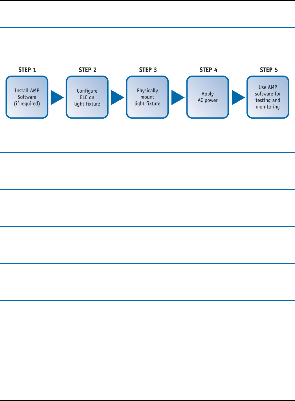
New Fixture Installation Overview
The following is a basic workflow for new Emergency Light fixture installation.
AMP Software Installation
AMP software must be installed prior to retrofitting existing Emergency Light fixtures
ELC Configuration
It is highly recommended that you configure the ELC prior to physically mounting the fixture.
Physically Mount Emergency Light Fixture
Physically mount the Emergency Light fixture at its intended location.
Apply AC Power
Apply AC power to the light fixture when all connections have been made
Setup Test and Monitoring on AMP Software
Setup AMP software for periodic/annual testing. The AMP software also monitoring the Emergency
Light system for bulb failures, current, and other parameters.
Installation and User Guide Emergency Light Monitoring
10
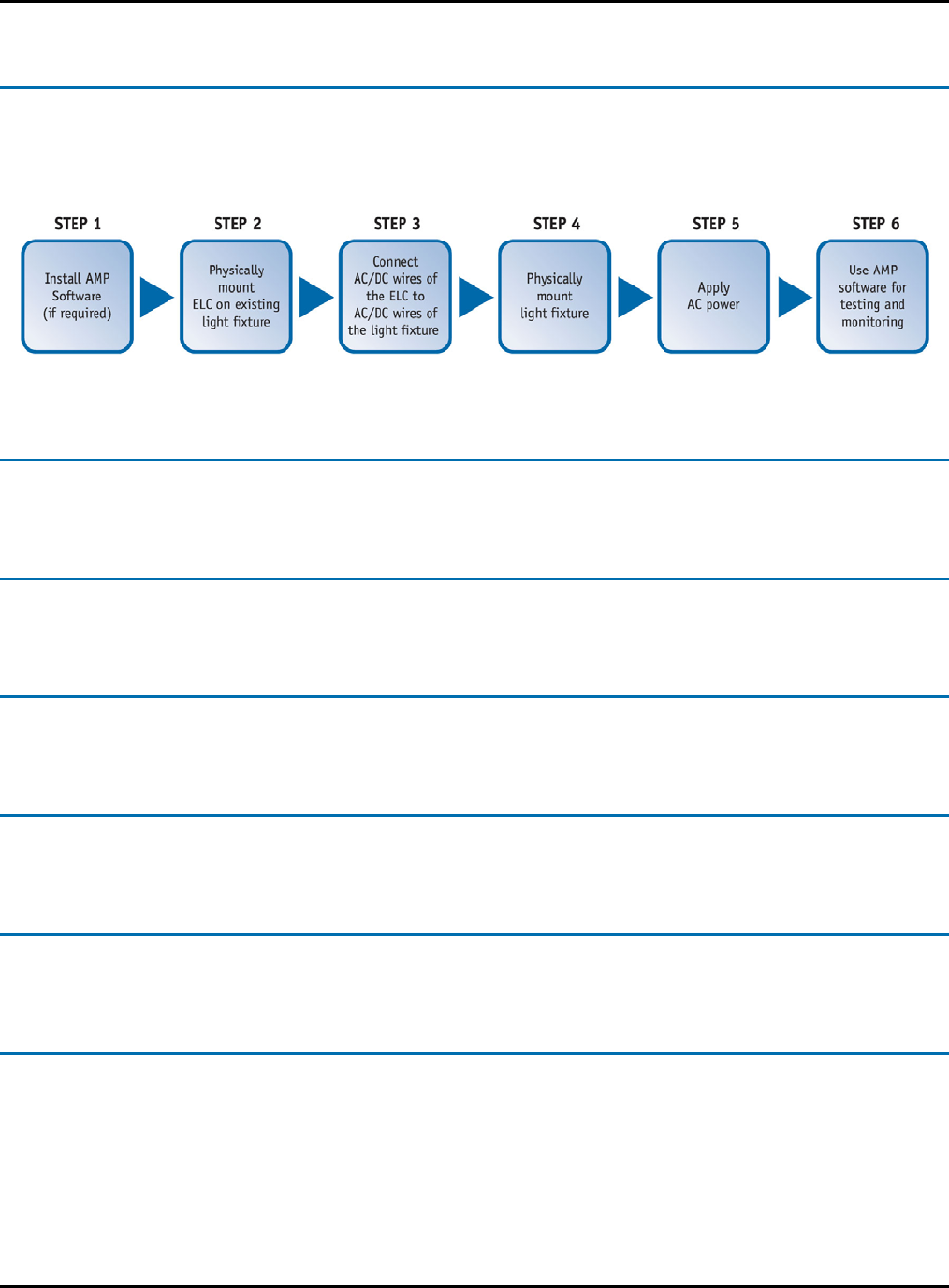
Retrofit Installation Overview
The following is a basic workflow for retrofitting existing Emergency Light fixtures with the Emergency
Light Controller (ELC).
AMP Software Installation
AMP software must be installed prior to retrofitting existing Emergency Light fixtures
ELC Configuration
It is highly recommended that you configure the ELC prior to physically mounting the fixture.
Physically Mount Emergency Light Fixture
Physically mount the Emergency Light fixture at its intended location.
Integrate ELC Into Existing Light Fixture
For retrofit scenarios, integrate the ELC into the existing light fixture.
Apply AC Power
Apply AC power to the light fixture when all connections are completed.
Setup Test and Monitoring on AMP Software
Setup AMP software for periodic/annual testing. The AMP software also monitoring the Emergency
Light system for bulb failures, current, and other parameters.
Emergency Light Monitoring Installation and User Guide
11
Emergency Light Controller
The Emergency Light Controller is a major component of the overall Emergency Light Monitoring
solution. The ELC may be integrated with a customer’s existing emergency light fixtures or alternatively
be pre-integrated into a light fixture from Primex Wireless (ELC Integrated Fixture).
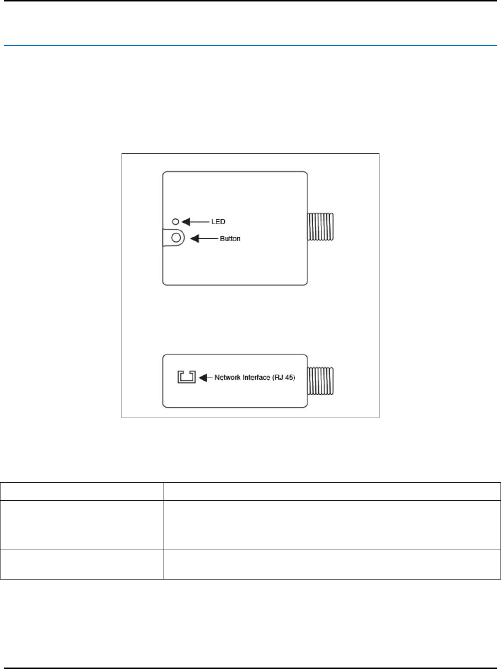
The Emergency Light Controller (ELC) is a device that is physically connected to an Emergency Light
fixture.
Figure 1: Emergency Light Controller
ELC ITEM FUNCTION
LED Visual indicator of ELC operating mode.
Button Used to select ELC operating modes/test states. The button is used
in conjunction with the LED to select modes/test states.
RJ-45 Connector Ethernet network interface – used for interface to a wired network
and device configuration.
Installation and User Guide Emergency Light Monitoring
12
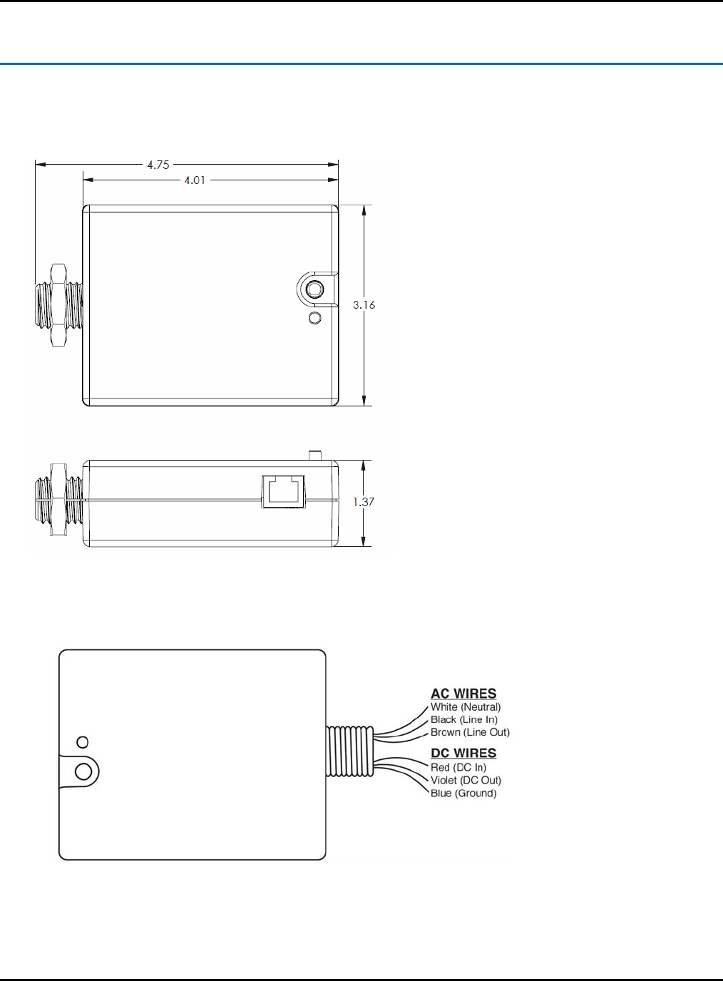
Emergency Light Controller (ELC) Specifications
1. The physical dimensions of the ELC case are as follows
L = 4.0 inches W = 3.16 inches H = 1.37 inches Diameter of ELC Shaft = .75 inches
Figure 2: ELC Physical Dimension
Figure 3: ELC Wires
Emergency Light Monitoring Installation and User Guide
13
Best Practices for Retrofitting an Emergency Light Fixture
The “ELC” (Emergency Light Controller) is positioned between emergency light power and emergency
light fixtures. In many cases, it must be integrated by removing an existing fixture and wiring in the ELC.
Consider the following before attempting a retrofit of an existing Emergency Light fixture:
1. Determine the best location on the light fixture to mount the ELC.
(Refer to “Mounting the ELC onto an Existing Light Fixture”)
2. Correctly identify the AC and DC power wires of the ELC and fixture
3. Make sure the fixture is in good working condition.
4. Make sure the light fixture has sufficient space in its case to accommodate the shaft of the ELC
and its associated wires.
5. Ensure that the installation of the ELC does not interfere with or obstruct wires or batteries in the
light fixture case.
6. If a suitable knock-out is available, identify it and use whatever tools are necessary to remove it.
Warning!
TO REDUCE THE RISK OF ELECTRIC SHOCK, DO NOT DRILL INTO LIGHT FIXUTRE
WIRING OR BATTERY!
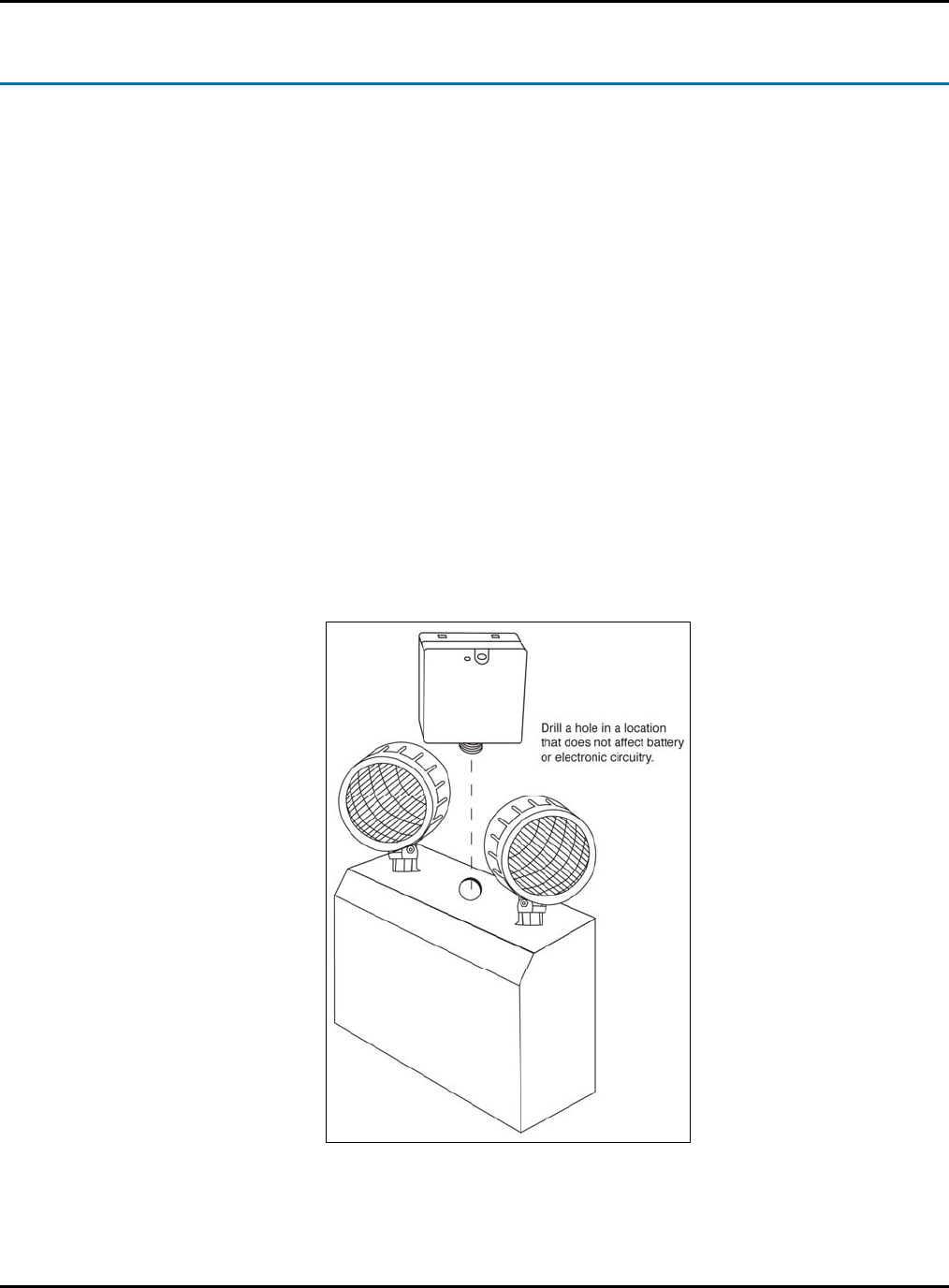
7. If drilling is required, use an appropriate drill bit, drill hole in the case if needed to insert the
threaded end of the ELC unit. Note that the positioning of the device is critical if it is desired to
have access to the button, as well as view of the LED.
8. After necessary hole is found, place the plastic washer on the threaded shaft of the ELC unit,
insert ELC unit into the hole and use the plastic nut to secure into place.
9. The ELC should face forward from whatever mounting position you select. This is to ensure that
the green power LED is visible for inspection.
Note: Order of operations – will need to actually find /create the hole and secure the ELC unit
before making the electrical connections.
Installation and User Guide Emergency Light Monitoring
14
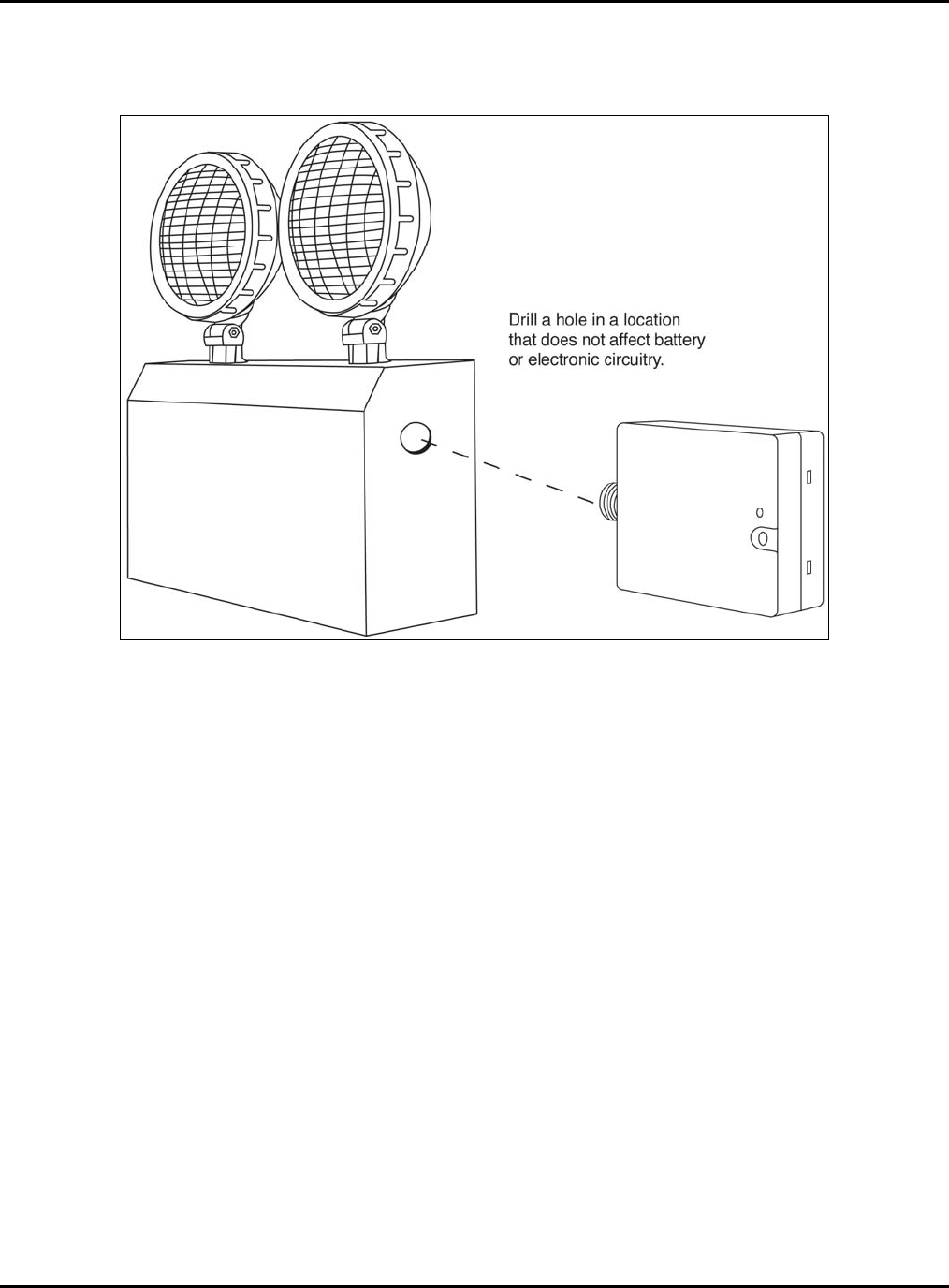
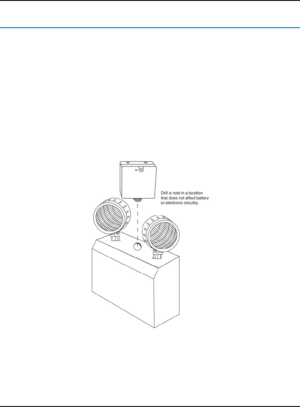
Mounting the ELC onto an Existing Light Fixture
The Emergency Light Controller (ELC) can be mounted on the side of an emergency light fixture or an
exit sign.
Perform the following basic steps to mount an ELC to a light fixture or exit sign:
1. Disconnect AC power from the emergency light fixture or exit sign.
2. Open the unit to gain access to its inside compartment.
3. Either drill a hole or remove a knock-out for mounting the ELC.
4. Make sure the mounting of the ELC does not interfere with the unit’s internal wiring or battery.
5. Place the threaded shaft into the hole and secure with provided hardware.
NOTE: The Emergency Light Controller (ELC) must face forward when mounted to an Emergency Light
fixture (as shown in the figure below). The LED and button should face the same direction as the bulbs
on the fixture.
Figure 4: Top Mounting the ELC
Emergency Light Monitoring Installation and User Guide
15
Figure 5: Side Mounting the ELC
Installation and User Guide Emergency Light Monitoring
16
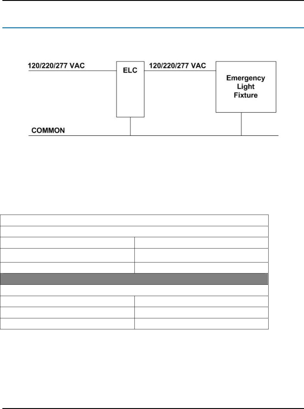
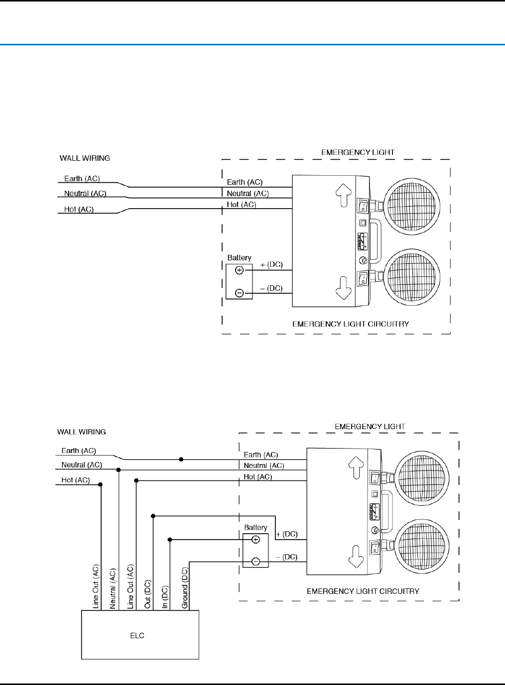
Color Codes for AC/DC Power
The Emergency Light Controller (ELC) is wired between AC power and an Emergency Light fixture.
Figure 6: ELC Wiring
It is very important for the person performing the retrofit to understand the color coding of the wires and
which ones are AC and DC.
Refer to the following table to gain an understanding of the color code of the ELC.
Emergency Light Controller (ELC) Wires
AC Wire Color Code
White Neutral
Black Line In
Brown Line Out
DC Wire Color Code
Red DC In
Violet DC Out
Blue DC Ground

Emergency Light Monitoring Installation and User Guide
17
AC Power Connections from the ELC
Note: The AC connections from the ELC unit will not have connectors. They will need to be connected
via wire nuts (or similar means) to provide necessary connection.
Perform the following steps to connect AC power from the ELC to an existing Emergency Light fixture:
1. Neutral (white in this example) – gets connected to the neutral AC connection that exists on the
emergency light. Note that this is usually white in color; please refer to user manual provided
with the emergency light to verify.
2. Line In (black in this example) – gets connected to the Line AC connection that exists on the
emergency light (coming from the existing building electrical wiring). Note that this is usually
black (US) in color; please refer to building electrician to verify.
3. Line Out (brown in this example) – gets connected to the line connection that exists on the
emergency light. Note that this is commonly black in color (120V) or orange (if using 277V);
please refer to user manual provided with the emergency light to verify.
DC Power Connections from the ELC
Perform the following steps to connect DC power from the ELC to an existing Emergency Light fixture:
1. DC In (red in this example) – gets connected to the positive battery connection in the existing
emergency light.
2. DC Out (Violet in this example)-gets connected from the ELC to the Regulator Board on a light
fixture.
3. DC Ground (Blue in this example) – gets connected to the ground side of a light fixture.
Installation and User Guide Emergency Light Monitoring
18
Wiring on the ELC
The following graphic depicts before and after AC/DC wiring of the Emergency Light Controller (ELC).
Before Integration of ELC in Light Fixture
After Integration of ELC in Light Fixture
Emergency Light Monitoring Installation and User Guide
19
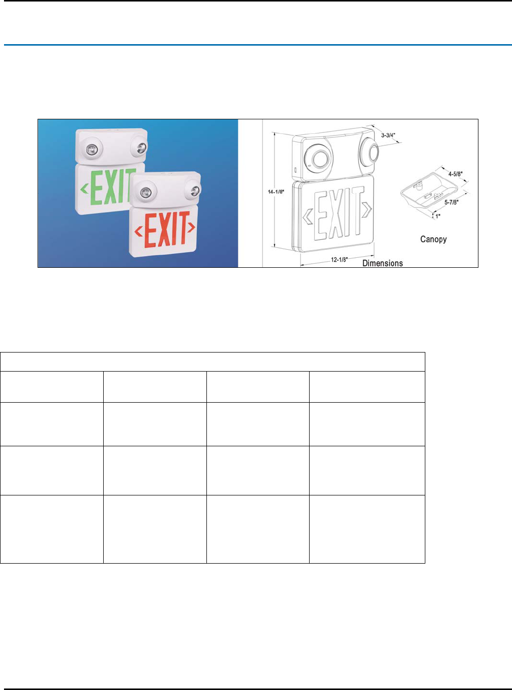
The ELC Emergency Light Fixture
Primex Wireless offers a line of Emergency Light fixtures with the ELC pre-integrated and ready for
installation. Available in standard fixture format and a combination emergency light / exit sign, these
units require no modification prior to deployment.
Figure 7: ELC Emergency Light Fixture
The ELC Emergency Light Fixture has the following specifications:
ELC Emergency Light Fixture Features
Housing Snap-Together
design
Letters 6” high
with ¾ stroke
Eyeball shape light
heads
Mounting Wall, side, or
ceiling mounting
Lightweight design Housing snaps to
canopy (for ceiling
mount applications)
Electrical 120/277 VAC Low power
consumption:
2.3 watts
LED indicator light
and push-button test
switch
Battery Lead-Calcium
Battery
24 hours recharge
after 90 minute
discharge
Certain lights will
disconnect from the
battery when battery
voltage falls below a
specific threshold.
Installation and User Guide Emergency Light Monitoring
20
Installing the ELC Emergency Light Fixture
Perform the following steps to install the ELC Emergency Light Fixture:
1. Physically mount the ELC Emergency Light fixture
2. Apply AC power to the unit.
3. Remove case to gain access to the fixture’s wiring.
4. The unit comes with the “red” lead disconnected from the battery.
5. Connect the “red” wire to the positive terminal of the battery on the ELC fixture.
6. Test light for functionality
Figure 8: The ELC Emergency Light Fixture

Emergency Light Monitoring Installation and User Guide
21
Configuring the Emergency Light Controller (ELC)
There are several factors to consider when configuring the Emergency Light Controller (ELC):
Issue Implications
Retro fit an existing light fixture • Light fixture compatibility with ELC
• Configure before you mount fixture
Installing new light fixture with ELC integrated • Configure ELC before mounting
• Wired or Wireless network
Interfacing to an Ethernet (wired) network
Interfacing to a wireless network
Configure ELC before or after physically mounting
a light fixture
Auto-Configuration:
a) Connect to a network (wired Ethernet)
b) Connect to a wireless network
c) Discovery and Auto-Configuration
d) Disconnect Power Supply
Manual Configuration:
a) Connect ELC to laptop via cable
b) Place ELC in Configuration mode
c) Configure network settings (wired or wireless)
d) Disconnect Power Supply

Installation and User Guide Emergency Light Monitoring
22
ELC Modes of Operation
The Emergency Light Controller (ELC) has several modes of operation. The following button
sequences will manually control the ELC from the unit itself (without using SNS software). It will work
with the LED to signify ELC modes of operation.
User presses the ELC button Mode of Operation
Press the button (1X) Check in with the AMP; LED = flash 1x then wait
for a second, flash 1x .
Press the button (2X) Periodic test; LED = flash 2x then wait for a
second, flash 2x.
Press the button (3X) Annual test; LED = flash 3x then wait for a
second, flash 3x.
Press the button (4X) Calibration (24 hour hang); LED = flash 4x then
wait for a second, flash 4x.
Press and hold the button for 5 seconds Configuration Mode
Important Notes
Make note of the following when manually configuring the Emergency Light Controller (ELC):
• If the user hits the button during any of these tests, the test will be cancelled. However, unit will
check-in to the SNS AMP server.
• There is a 1 second timeout between button presses (so user has up to 1 second to press the
button again) to advance in the selection menu. If that second elapses, start the state that is
currently selected.
• If the user continues to try and cycle through the menu after all options are exhausted, the ELC
returns to normal operation and gives user a visual indication that there was an issue (ran out of
options, returning to normal operation).
• To enter configuration mode: press and hold for 5 seconds

Emergency Light Monitoring Installation and User Guide
23
Using the AMP for Emergency Light Testing and
Monitoring
Once an Emergency Light fixture is on a network and recognized by AMP software, you can perform
the following tasks:
• Add a new Emergency Light to the system
• Assign Emergency Lights to specific groups (5th floor lights, cafeteria lights etc).
• Configure tests for Emergency Lights
• View Emergency Lights status
• Generate Emergency Light test history
• View Emergency Light network connection history
• View Emergency Lights through a floor plan template
For additional information on testing and monitoring Emergency Lights, please refer to the “AMP User
Guide for Emergency Lights”.

Installation and User Guide Emergency Light Monitoring
24
Troubleshooting the Installation
If you have issues during installation, please refer to the following table:
Troubleshooting Issue Possible Resolution
Lamps on light fixture do not illuminate during test 1. Improper wiring
2. Bulb burned out
Cannot access the AMP server 1. Check network interface (wired/wireless)
LED on ELC does not illuminate 2. Check power to ELC
No test data/monitoring data on SNS AMP 1. Check network interface (wired/wireless)
2. Defective ELC
Light fixture provides less than 8 hours of
emergency lighting during test.
1. Improper charging of batteries
2. Faulty batteries