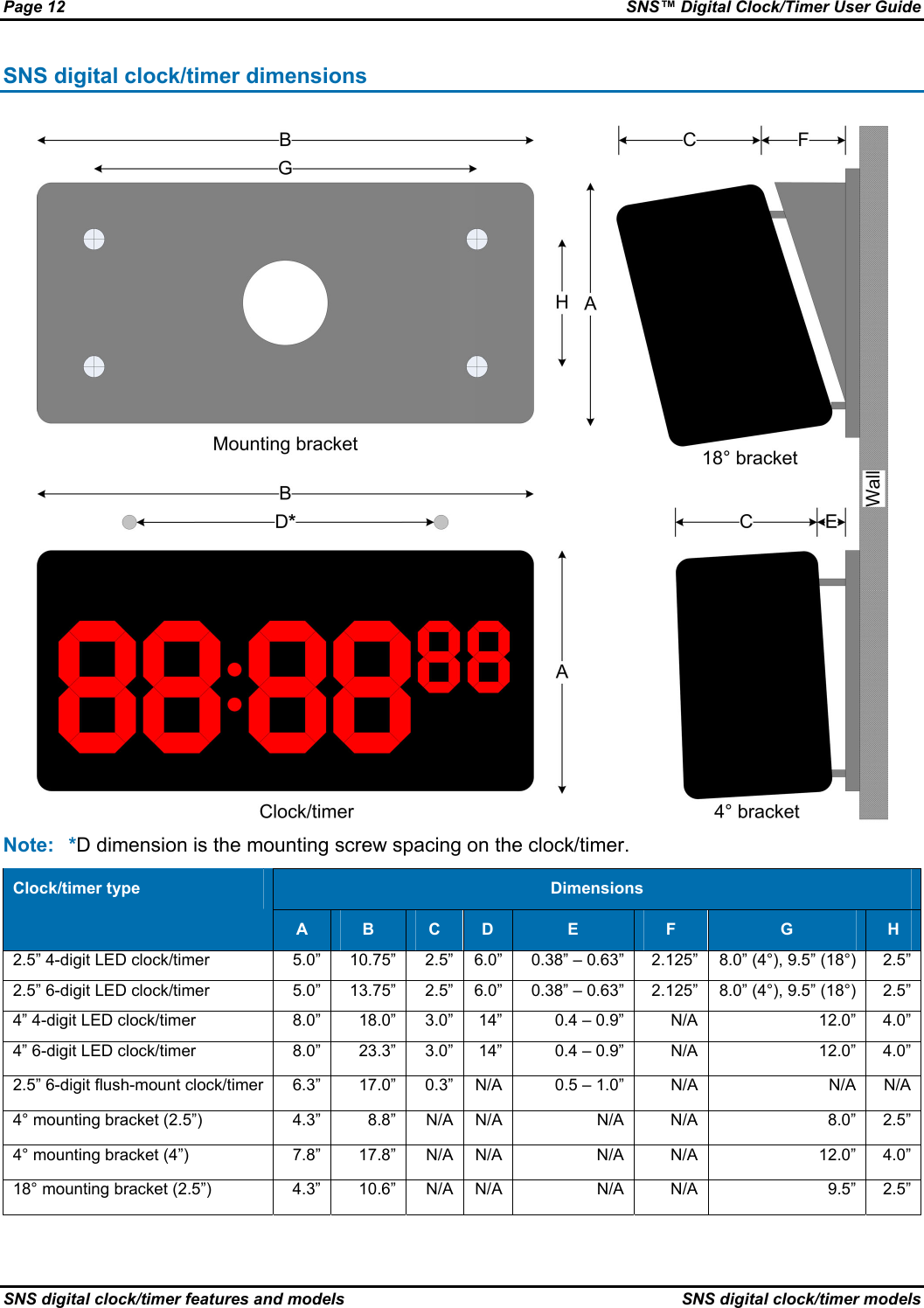
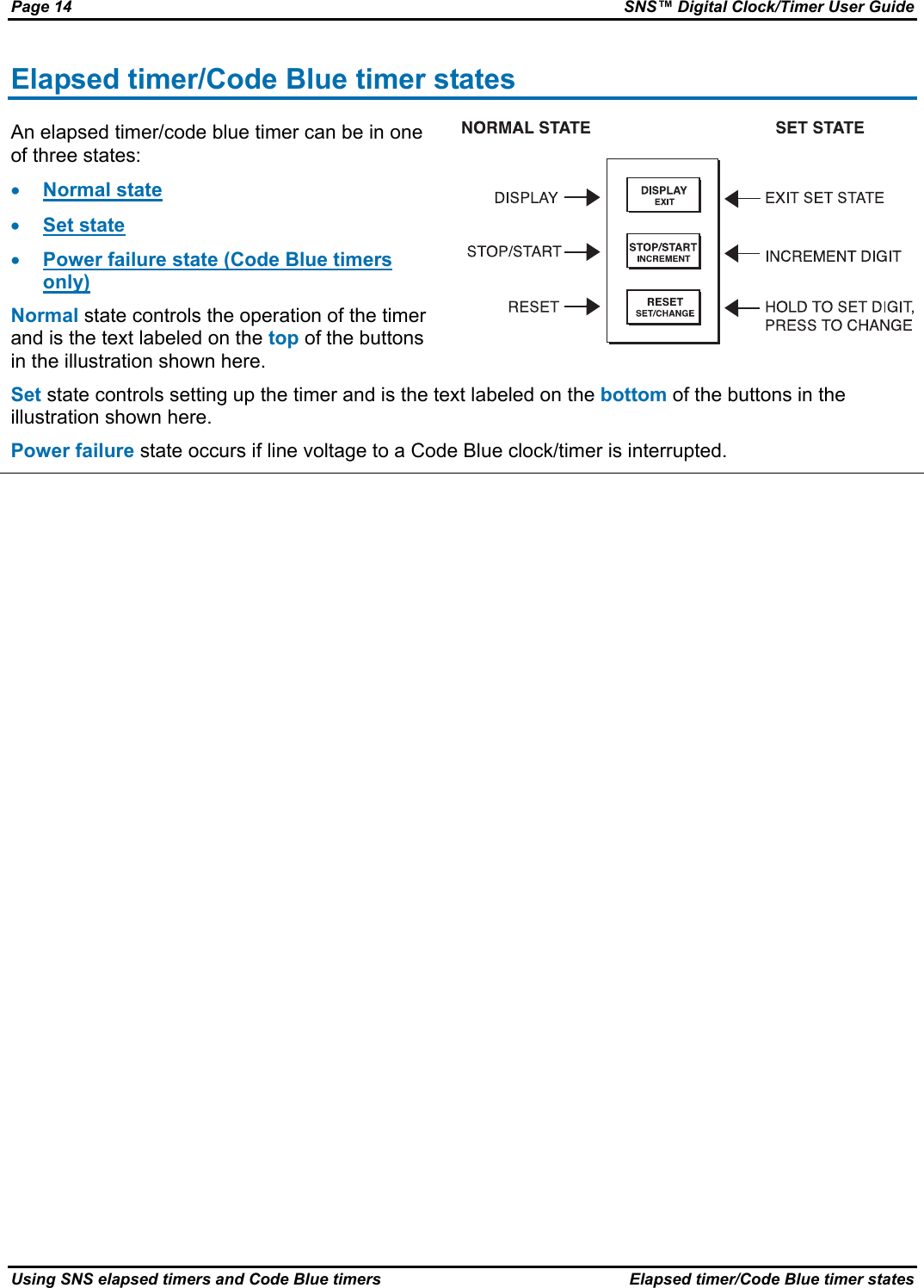
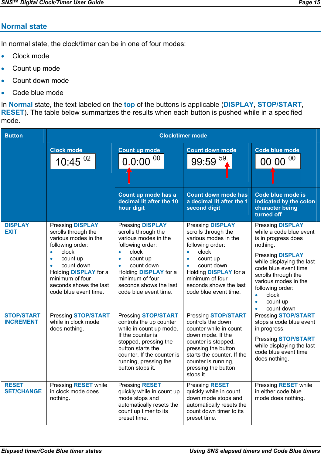
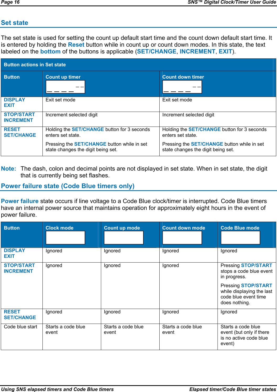
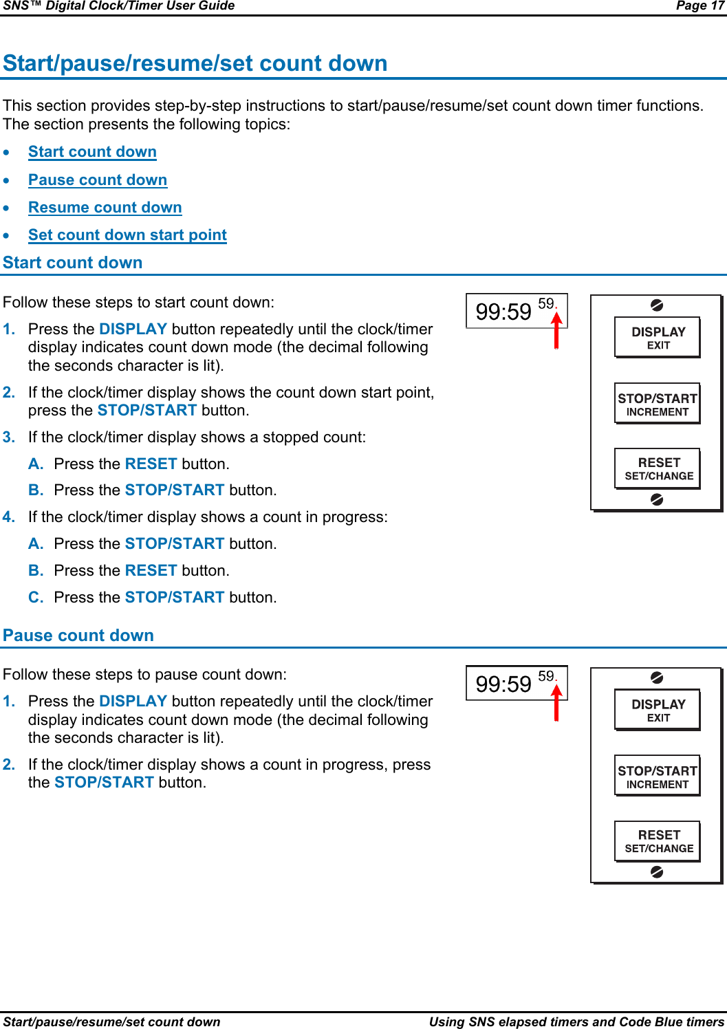
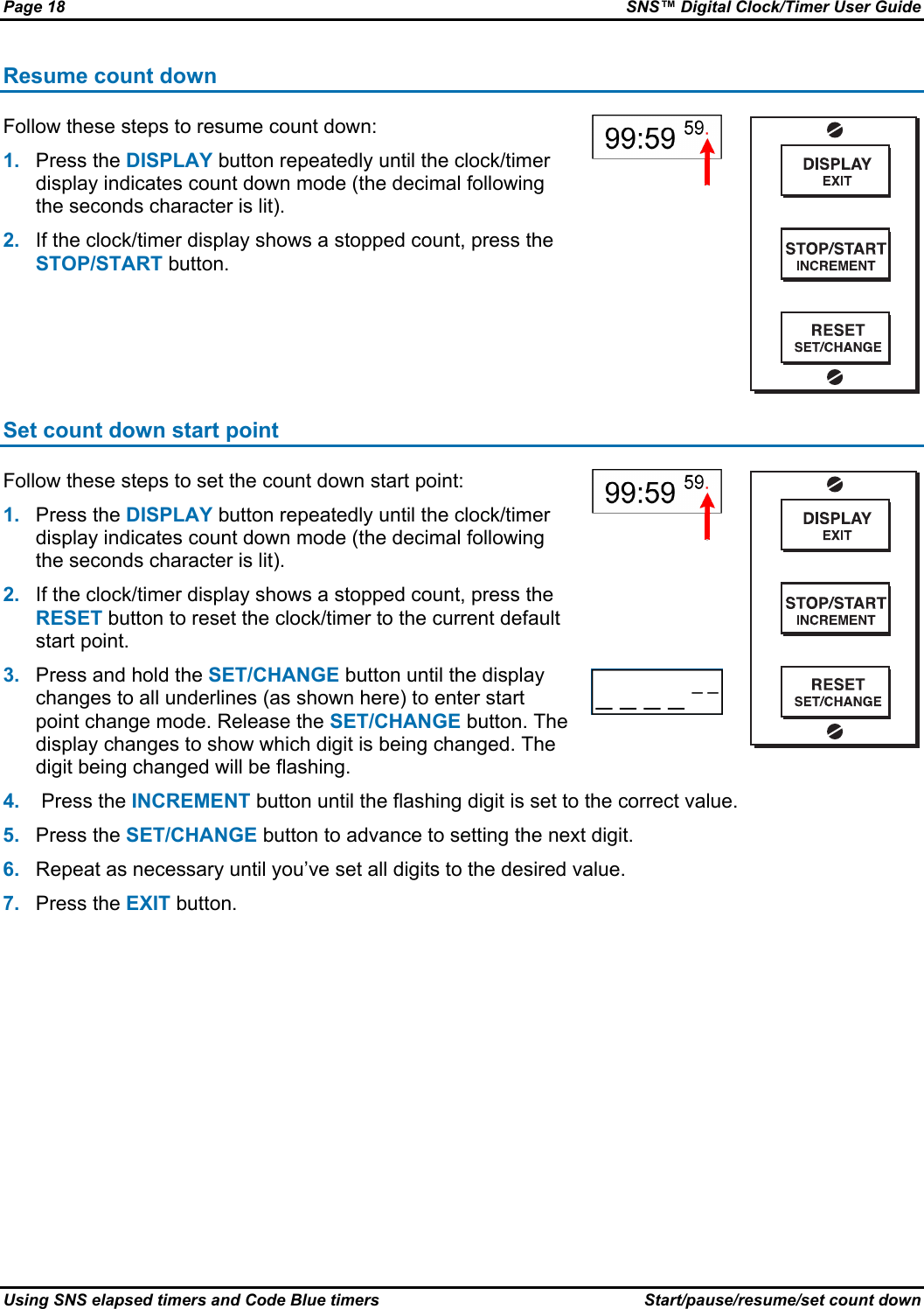
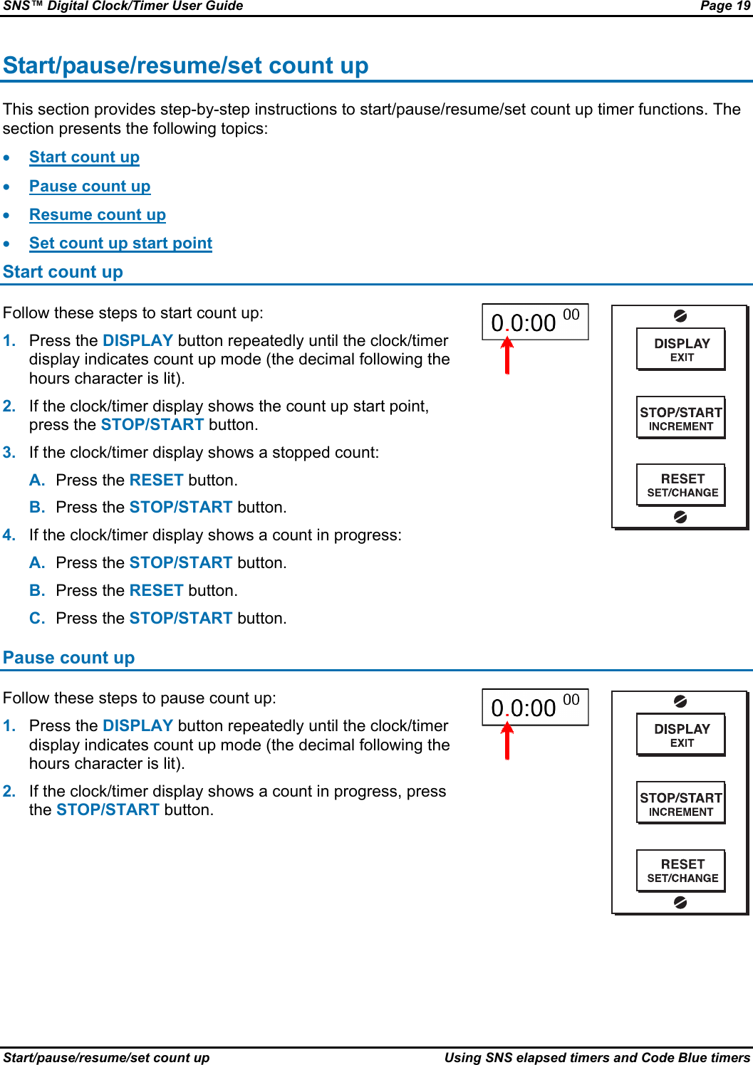
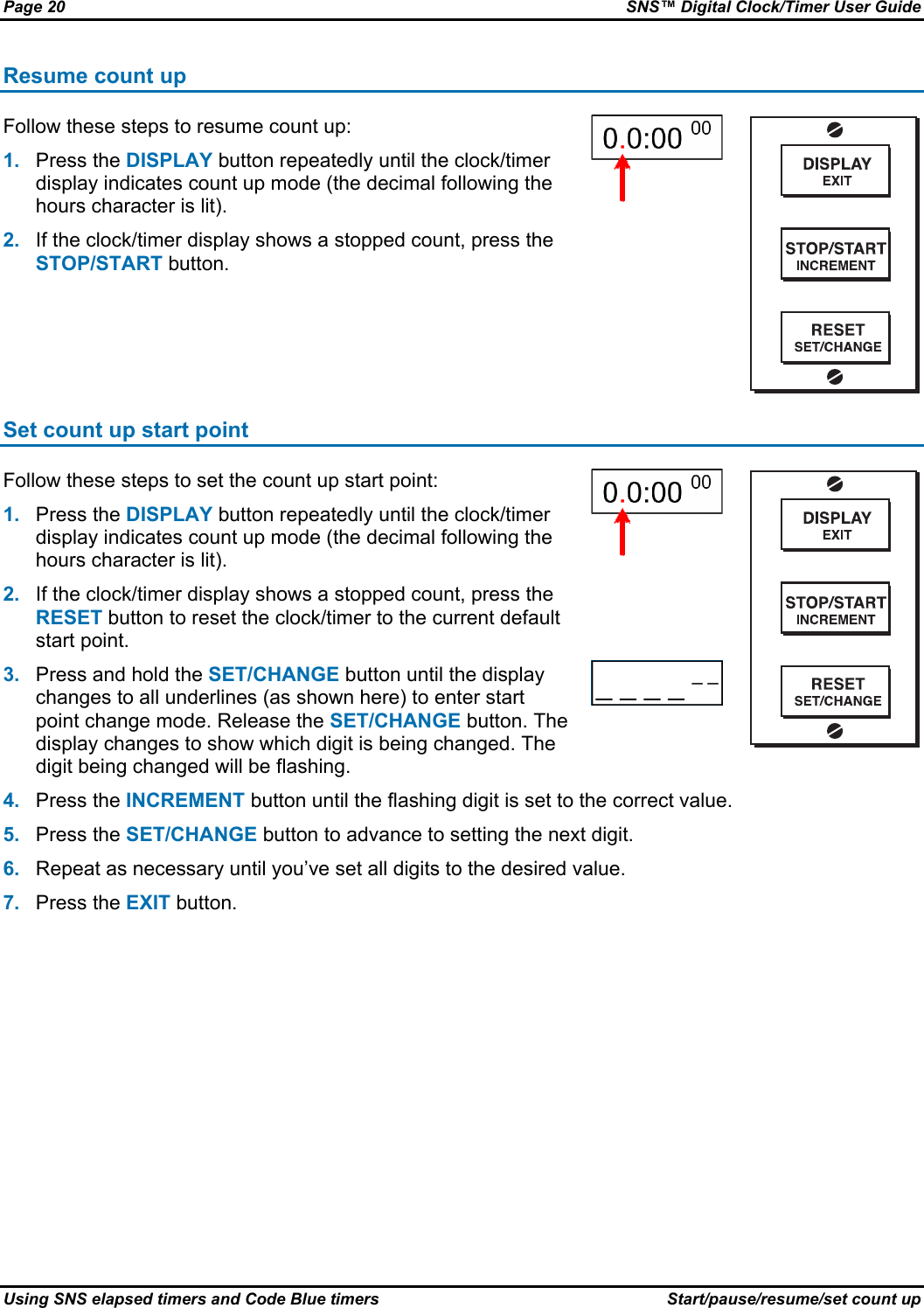
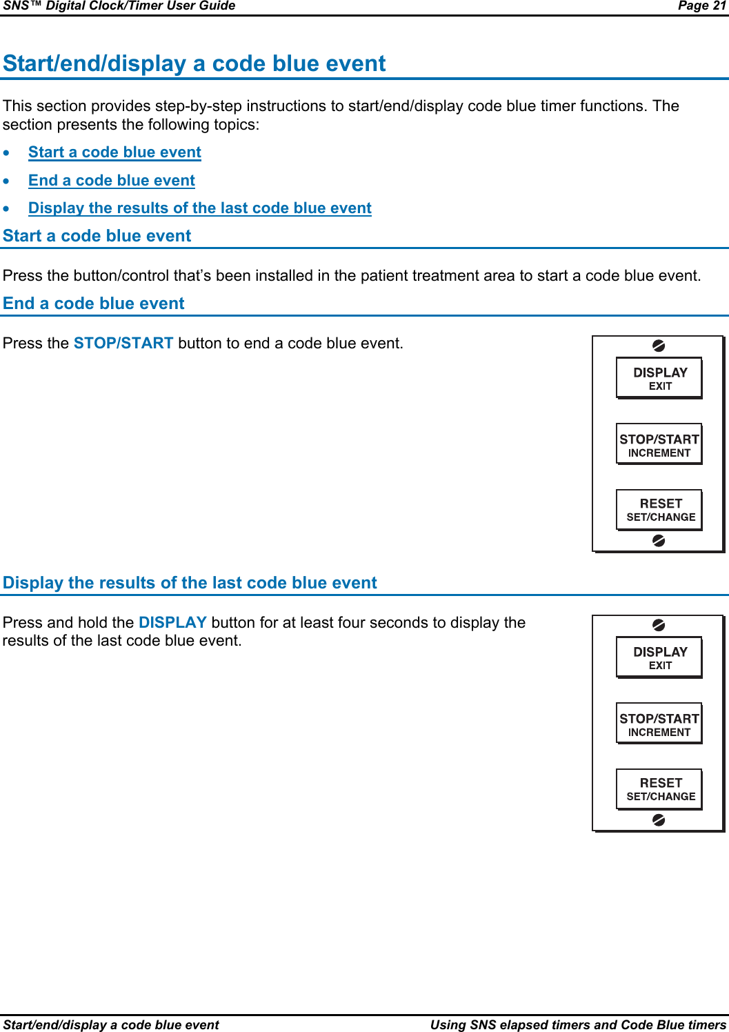
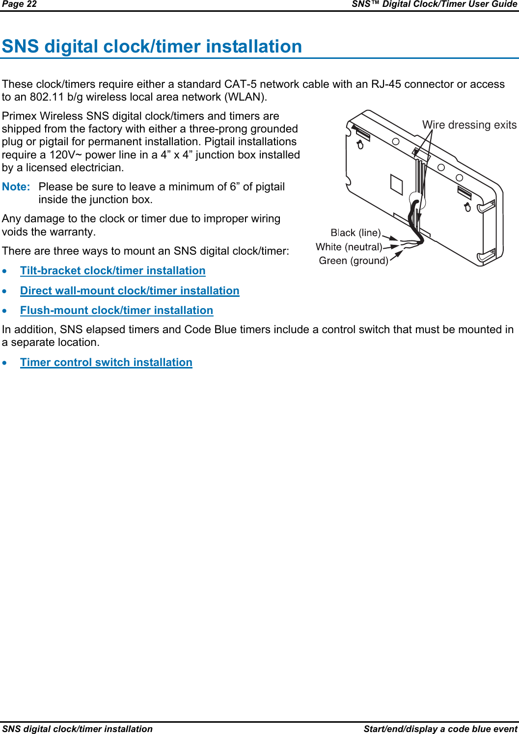
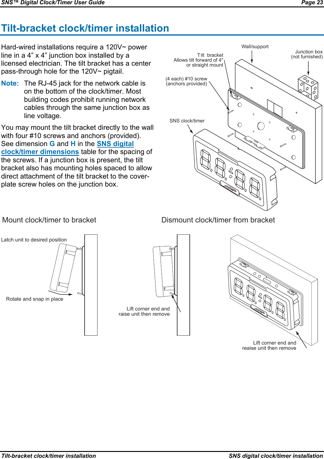
Primex Wireless SNSL Synchronous Network System LED Clocks User Manual SNS Digital Clock Timer User Guide

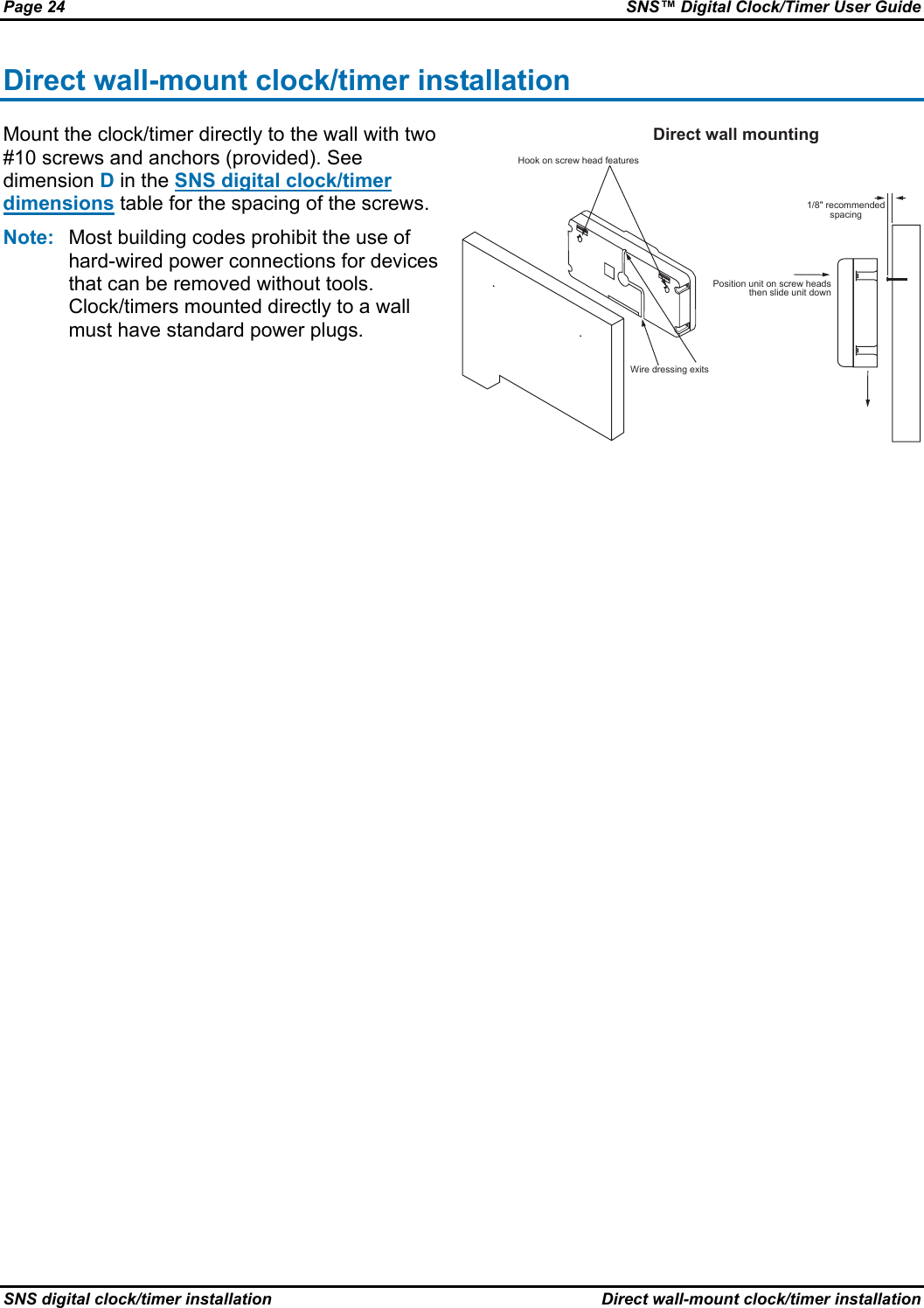
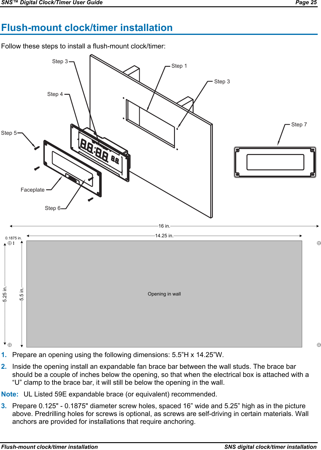
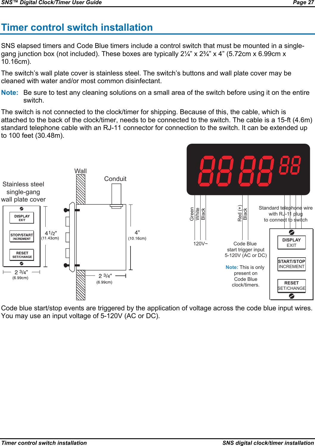
Primex Wireless, Inc. Synchronous Network System LED Clocks SNS Digital Clock Timer User Guide

User manual

 SNS™ Digital Clock/Timer User Guide
Page ii  SNS™ Digital Clock/Timer User Guide Notices   Notices © Copyright 2008, Primex Wireless; all rights reserved. Trademarks SNS and AMP are trademarks of Primex Wireless, Inc. Contact Primex Wireless Web: http://www.primexwireless.com/ Email:  support@primexwireless.com   United States  Canada  United Kingdom Telephone (800) 537-0464  (800) 330-1459  0800-3896996 Hours 7:00am - 5:00pm Central  7:00am - 5:00pm Central  8:30am – 5:00pm GMT Fax (262) 248-0061  (905) 952-0134  01422-349462 Mailing address Primex Wireless 965 Wells Street Lake Geneva, Wisconsin 53147 Primex Wireless 1310 Kerrisdale Blvd.  Unit #4 Newmarket, ON L3Y 8V6 Primex Wireless Limited Dean Clough Halifax West Yorkshire HX3 5AX
SNS™ Digital Clock/Timer User Guide  Page iii  Contents Contents Introduction.............................................................................................................................................1 Precautions and regulatory compliance statements ...........................................................................2 SNS digital clock/timer features and models .......................................................................................4 SNS digital clock features ...................................................................................................................5 Display options ............................................................................................................................................. 5 Mounting options .......................................................................................................................................... 5 SNS Elapsed Timer digital timer features ...........................................................................................6 Up counter features ...................................................................................................................................... 6 Down counter features ................................................................................................................................. 6 Mounting options .......................................................................................................................................... 6 SNS Code Blue digital timer features .................................................................................................7 Up counter features ...................................................................................................................................... 7 Down counter features ................................................................................................................................. 7 Code Blue timer features.............................................................................................................................. 7 Mounting options .......................................................................................................................................... 8 SNS digital clock/timer models ...........................................................................................................9 2.5" x 4-digit red wall mount ......................................................................................................................... 9 2.5" x 4-digit green wall mount ..................................................................................................................... 9 2.5" x 6-digit red wall mount ....................................................................................................................... 10 2.5" x 6-digit red flush mount ...................................................................................................................... 10 4" x 4-digit red wall mount .......................................................................................................................... 11 4" x 6-digit red wall mount .......................................................................................................................... 11 SNS digital clock/timer dimensions ............................................................................................................ 12 Using SNS elapsed timers and Code Blue timers .............................................................................13 Elapsed timer/Code Blue timer states...............................................................................................14 Start/pause/resume/set count down .................................................................................................17 Start count down......................................................................................................................................... 17 Pause count down ...................................................................................................................................... 17 Resume count down................................................................................................................................... 18 Set count down start point .......................................................................................................................... 18 Start/pause/resume/set count up ......................................................................................................19 Start count up ............................................................................................................................................. 19 Pause count up........................................................................................................................................... 19 Resume count up ....................................................................................................................................... 20 Set count up start point............................................................................................................................... 20 Start/end/display a code blue event..................................................................................................21 Start a code blue event............................................................................................................................... 21 End a code blue event................................................................................................................................ 21 Display the results of the last code blue event ........................................................................................... 21 SNS digital clock/timer installation .....................................................................................................22 Tilt-bracket clock/timer installation ....................................................................................................23 Direct wall-mount clock/timer installation ..........................................................................................24 Flush-mount clock/timer installation..................................................................................................25 Timer control switch installation ........................................................................................................27
  Introduction Primex Wireless’s Synchronous Network System (SNS™) digital clock/timers are equipped with both a wireless 802.11 b/g interface and a wired Ethernet port interface. Viewable up to 150 feet away, these bright LED-digit clock/timers are perfect for hallways and large rooms. They’re also easy to install – simply connect the power source and the clock/timer is instantly synchronized to the Primex Wireless system. Primex Wireless digital clock/timers can be installed anywhere indoors within range of an 802.11 b/g access point. The clock/timers are able to connect in an existing wireless LAN (WLAN), supporting a wide variety of security protocols. The initial setup procedure for all SNS digital clock/timers can be done by Primex Wireless prior to shipping or can be done with the Configuration Tool software at your facility in a convenient central location such as a maintenance area or at the final location of the clock/timer. For detailed instructions on the use of the Configuration Tool software, please see the Primex Wireless Configuration Tool Software User Guide. Once the digital clock/timers are configured using the Configuration Tool software, settings can be altered using Primex’s Applications Management Platform (AMP™). AMP has features to determine the signal strength of the digital clock’s reception. The digital clock/timers connect to the WLAN only at the times configured with AMP or the Configuration Tool software. Any changes in configuration of a digital clock/timer via AMP will be transmitted to the digital clock/timer the next time the digital clock/timer connects to the WLAN. For detailed instructions on the use of AMP, please see the Primex Wireless Applications Management Platform (AMP™) User Guide. This document describes the installation and configuration of Primex Wireless SNS digital clock/timers and contains the following sections: • SNS digital clock/timer features and models • Using SNS elapsed timers and Code Blue timers • SNS digital clock/timer installation
Page 2  SNS™ Digital Clock/Timer User Guide Introduction  Precautions and regulatory compliance statements Precautions and regulatory compliance statements This section contains mandatory precautions and regulatory compliance statements. Safety precautions The SNS digital clock/timer must be connected to a properly grounded outlet and it is designed for indoor use only. It is not weather protected. Operating the SNS digital clock/timer outdoors, or in wet areas is an electrical hazard and may damage the SNS digital clock/timer while nullifying the warranty. The SNS digital clock/timer must be connected to a properly grounded outlet and it is designed for indoor use only. Equipment precautions • To avoid possible electric shock and damage to the SNS digital clock/timer, make sure that it is unplugged when working on it. • The socket-outlet shall be installed near the equipment and shall be easily accessible. • For healthcare facilities, clock/timers are not intended for patient use and must not be installed within 6ft (2m) of patient contact. • Clock/timers are cleanable with a cloth moistened with water or a common disinfectant. Caution  Be sure to test any cleaning solutions on a small area of the clock/timer before using it on the entire clock/timer. FCC compliance Any changes or modifications not expressly approved by the party responsible for compliance could void the user's authority to operate the equipment. FCC radio frequency interference This equipment has been tested and found to comply with the limits for a Class B digital device, pursuant to Part 15 of the FCC rules. These limits are designed to provide reasonable protection against harmful interference in a residential installation. This equipment generates, uses and can radiate radio frequency energy and, if not installed and used in accordance with the instructions, may cause harmful interference to radio communications. However, there is no guarantee that interference will not occur in a particular installation. If this equipment does cause harmful interference to radio or television reception, which can be determined by turning the equipment off and on, the user is encouraged to try to correct the interference by one or more of the following measures: • Reorient or relocate the receiving antenna. • Increase the distance between the equipment and the receiver. • Connect the equipment to an outlet on a circuit different from that to which the receiver is connected. • Consult the dealer or an experienced radio/TV technician for help.
SNS™ Digital Clock/Timer User Guide  Page 3 Precautions and regulatory compliance statements  Introduction FCC radiation exposure limits To comply with FCC RF exposure requirements in section 1.1307, a minimum separation distance of 7.87” (20 cm) is required between the antenna and all persons.
Page 4  SNS™ Digital Clock/Timer User Guide SNS digital clock/timer features and models  Precautions and regulatory compliance statements SNS digital clock/timer features and models This section provides information about SNS digital clock/timer features and models. It presents the following topics: • SNS digital clock features • SNS Elapsed Timer digital timer features • SNS Code Blue digital timer features • SNS digital clock/timer models
SNS™ Digital Clock/Timer User Guide  Page 5 SNS digital clock features  SNS digital clock/timer features and models SNS digital clock features All SNS clock/timers include either an 18” pigtail or a 9ft cord with a three-prong grounding plug. Display options • 12-hour/24-hour mode • PM indicator • Alternate display of date and time • Four levels of brightness: 100%, 75%, 50%, 25% Mounting options • Bracket mounting • 4° tilt mounting • 18° tilt mounting • Direct wall mounting (no bracket) • Flush mount
Page 6  SNS™ Digital Clock/Timer User Guide SNS digital clock/timer features and models  SNS Elapsed Timer digital timer features SNS Elapsed Timer digital timer features The Primex Wireless Elapsed Timer is a multi-function product. It has the capability of functioning as a normal clock and as an elapsed timer with both count up and count down options. It functions in much the same way as a standard digital clock. The elapsed timer is two timers in one: • Up counter The up counter can count up from any preset time to 99:59:59 (99 hours, 59 minutes, 59 seconds). • Down counter The count down timer can count down from a preset time to 00:00:00. Up counter features • The decimal point on the far left (near the 10 hour digit) lights up to indicate up counter function. • The user can preset count up start time. • Up counters can count from 00:00:00 to 99:59:59 (99 hours, 59 minutes, 59 seconds). The display flashes every second and the clock beeps for 3 seconds when 99:59:59 is reached. Down counter features • The decimal point on the far right (near the minutes/seconds digits) lights up to indicate down counter function. • The user can preset count down start time. • Down counters can count from 99:59:59 to 00:00:00. The display flashes every second and the clock beeps for 3 seconds when 00:00:00 is reached. Mounting options • Bracket mounting • 4° tilt mounting • 18° tilt mounting • Direct wall mounting (no bracket) • Flush mount
SNS™ Digital Clock/Timer User Guide  Page 7 SNS Code Blue digital timer features  SNS digital clock/timer features and models SNS Code Blue digital timer features The Primex Wireless Code Blue timer is a multi-function product. It has the capability of functioning as a normal clock, code blue timer, and an elapsed timer with both count up and count down options. It functions in much the same way as a standard digital clock. The Code Blue timer is three timers in one: • Up counter The up counter can count up from any preset time to 99:59:59 (99 hours, 59 minutes, 59 seconds). • Down counter The count down timer can count down from a preset time to 00:00:00. • Code Blue timer The code blue timer counts up from 00:00:00 when triggered by a code blue system. Up counter features • The decimal point on the far left (near the 10 hour digit) lights up to indicate up counter function. • The user can preset count up start time. • Up counters can count from 00:00:00 to 99:59:59 (99 hours, 59 minutes, 59 seconds). The display flashes every second and the clock beeps for 3 seconds when 99:59:59 is reached. Down counter features • The decimal point on the far right (near the minutes/seconds digits) lights up to indicate down counter function. • The user can preset count down start time. • Down counters can count from 99:59:59 to 00:00:00. The display flashes every second and the clock beeps for 3 seconds when 00:00:00 is reached. Code Blue timer features • Upon receiving the code blue input, the clock immediately enters code blue mode, and starts counting up from 00:00:00. • Code Blue mode is indicated by the colon, dash and decimal points not being lit. (in both viewing and counting modes) • Any other counting events remain operational in the background. • Time duration of the last code blue event is stored in memory, and can be viewed until a new code blue is triggered. • A code blue count can be halted by pressing the STOP/START button. Pressing either DISPLAY or RESET is ignored while in code blue mode. • Triggering of the code blue input while a current code blue is counting will be ignored. • Upon reaching 99:59:59, the Code Blue timer will beep for 3 seconds. • This clock has a power outage memory backup and will maintain the correct time and continue code blue timing for approximately 8 hours without power.
Page 8  SNS™ Digital Clock/Timer User Guide SNS digital clock/timer features and models  SNS Code Blue digital timer features Note:  This feature requires a minimum of 1 hour of charging time. • Code Blue trigger voltage: 5-120V (AC or DC). Note:  When using DC, be sure to use the correct polarity (red is positive). Mounting options • Bracket mounting • 4° tilt mounting • 18° tilt mounting • Direct wall mounting (no bracket) • Flush mount
SNS™ Digital Clock/Timer User Guide  Page 9 SNS digital clock/timer models  SNS digital clock/timer features and models SNS digital clock/timer models This section provides tables detailing the available SNS digital clock/timer models and their dimensions: • 2.5" x 4-digit red wall mount • 2.5" x 4-digit green wall mount • 2.5" x 6-digit red wall mount • 2.5" x 6-digit red flush mount • 4" x 4-digit red wall mount • 4" x 6-digit red wall mount • SNS digital clock/timer dimensions 2.5" x 4-digit red wall mount  US model #  Cable type  Mounting option Current draw @ 120V~ Weight (lbs) Type SNS7B200  9 foot cord with plug  4° tilt bracket  210 mA  2.6  LED clock SNS7Y200-1  18 inch pigtail  4° tilt bracket  210 mA  2.26  LED clock SNS7B212  9 foot cord with plug  18° tilt bracket  210 mA  2.8  LED clock SNS7Y212-1  18 inch pigtail  18° tilt bracket  210 mA  2.46  LED clock  2.5" x 4-digit green wall mount  US model #  Cable type  Mounting option Current draw @ 120V~ Weight (lbs) Type SNS7B200G  9-foot cord with plug  4° tilt bracket  230 mA  2.6  LED clock SNS7Y200G-1  18-inch pigtail  4° tilt bracket  230 mA  2.26  LED clock SNS7B212G  9-foot cord with plug  18° tilt bracket  230 mA  2.8  LED clock SNS7Y212G-1  18-inch pigtail  18° tilt bracket  230 mA  2.46  LED clock
Page 10  SNS™ Digital Clock/Timer User Guide SNS digital clock/timer features and models  SNS digital clock/timer models 2.5" x 6-digit red wall mount  US model #  Cable type  Mounting option Current draw @ 120V~ Weight (lbs) Type SNS7B202  9-foot cord with plug  4° tilt bracket  260 mA  2.96  LED clock SNS7Y202-1  18-inch pigtail  4° tilt bracket  260 mA  2.62  LED clock SNS7B419  9-foot cord with plug  18° tilt bracket  260 mA  3.16  LED clock SNS7Y419-1  18-inch pigtail  18° tilt bracket  260 mA  2.82  LED clock SNS7B202E  9-foot cord with plug  4° tilt bracket  260 mA  3.06  Elapsed timer SNS7Y202E-1  18-inch pigtail  4° tilt bracket  260 mA  2.72  Elapsed timer SNS7B419E  9-foot cord with plug  18° tilt bracket  260 mA  3.26  Elapsed timer SNS7Y419E-1  18-inch pigtail  18° tilt bracket  260 mA  2.92  Elapsed timer SNS7B202C  9-foot cord with plug  4° tilt bracket  260 mA  3.1  Code Blue timer SNS7Y202C-1  18-inch pigtail  4° tilt bracket  260 mA  2.76  Code Blue timer SNS7B419C  9-foot cord with plug  18° tilt bracket  260 mA  3.3  Code Blue timer SNS7Y419C-1  18-inch pigtail  18° tilt bracket  260 mA  2.96  Code Blue timer  2.5" x 6-digit red flush mount  US model #  Cable type  Mounting option Current draw @ 120V~ Weight (lbs) Type SNS7Y202F-1  18-inch pigtail  Flush mount  260 mA  2.88  LED clock SNS7Y202EF-1  18-inch pigtail  Flush mount  260 mA  2.98  Elapsed timer SNS7Y202CF-1  18-inch pigtail  Flush mount  260 mA  3.02  Code Blue timer
SNS™ Digital Clock/Timer User Guide  Page 11 SNS digital clock/timer models  SNS digital clock/timer features and models 4" x 4-digit red wall mount  US model #  Cable type  Mounting option Current draw @ 120V~ Weight (lbs) Type SNS7B201  9-foot cord with plug  4° tilt bracket  230 mA  6.02  LED clock SNS7Y201-1  18-inch pigtail  4° tilt bracket  230 mA  5.7  LED clock  4" x 6-digit red wall mount  US model #  Cable type  Mounting option Current draw @ 120V~ Weight (lbs) Type SNS7B203  9-foot cord with plug  4° tilt bracket  260 mA  7.3  LED clock SNS7Y203-1  18-inch pigtail  4° tilt bracket  260 mA  6.98  LED clock
Page 12  SNS™ Digital Clock/Timer User Guide SNS digital clock/timer features and models  SNS digital clock/timer models SNS digital clock/timer dimensions  Note: *D dimension is the mounting screw spacing on the clock/timer. Dimensions Clock/timer type A  B  C  D  E  F  G  H 2.5” 4-digit LED clock/timer  5.0”  10.75” 2.5” 6.0” 0.38” – 0.63”  2.125”  8.0” (4°), 9.5” (18°)  2.5” 2.5” 6-digit LED clock/timer  5.0”  13.75” 2.5” 6.0” 0.38” – 0.63”  2.125”  8.0” (4°), 9.5” (18°)  2.5” 4” 4-digit LED clock/timer  8.0”  18.0”  3.0”  14”  0.4 – 0.9” N/A  12.0” 4.0” 4” 6-digit LED clock/timer  8.0”  23.3”  3.0”  14”  0.4 – 0.9” N/A  12.0” 4.0” 2.5” 6-digit flush-mount clock/timer  6.3” 17.0” 0.3” N/A  0.5 – 1.0”  N/A  N/A  N/A 4° mounting bracket (2.5”)  4.3”  8.8” N/A N/A  N/A  N/A  8.0” 2.5” 4° mounting bracket (4”)  7.8”  17.8” N/A N/A  N/A  N/A  12.0” 4.0” 18° mounting bracket (2.5”) 4.3” 10.6” N/A N/A N/A N/A  9.5” 2.5”
SNS™ Digital Clock/Timer User Guide  Page 13 SNS digital clock/timer models  Using SNS elapsed timers and Code Blue timers Using SNS elapsed timers and Code Blue timers This section provides instructions for using SNS elapsed timers and Code Blue timers. The section presents the following topics: • Elapsed timer/Code Blue timer states • Start/pause/resume/set count down • Start/pause/resume/set count up • Start/end/display a code blue event
Page 14  SNS™ Digital Clock/Timer User Guide Using SNS elapsed timers and Code Blue timers  Elapsed timer/Code Blue timer states Elapsed timer/Code Blue timer states An elapsed timer/code blue timer can be in one of three states: • Normal state • Set state • Power failure state (Code Blue timers only) Normal state controls the operation of the timer and is the text labeled on the top of the buttons in the illustration shown here.  Set state controls setting up the timer and is the text labeled on the bottom of the buttons in the illustration shown here. Power failure state occurs if line voltage to a Code Blue clock/timer is interrupted.
SNS™ Digital Clock/Timer User Guide  Page 15 Elapsed timer/Code Blue timer states  Using SNS elapsed timers and Code Blue timers Normal state In normal state, the clock/timer can be in one of four modes: • Clock mode • Count up mode • Count down mode • Code blue mode In Normal state, the text labeled on the top of the buttons is applicable (DISPLAY, STOP/START, RESET). The table below summarizes the results when each button is pushed while in a specified mode. Clock/timer mode Count up mode  Count down mode  Code blue mode  Button Clock mode  Count up mode has a decimal lit after the 10 hour digit Count down mode has a decimal lit after the 1 second digit Code blue mode is indicated by the colon character being turned off DISPLAY EXIT Pressing DISPLAY scrolls through the various modes in the following order: • clock • count up • count down Holding DISPLAY for a minimum of four seconds shows the last code blue event time. Pressing DISPLAY scrolls through the various modes in the following order: • clock • count up • count down Holding DISPLAY for a minimum of four seconds shows the last code blue event time. Pressing DISPLAY scrolls through the various modes in the following order: • clock • count up • count down Holding DISPLAY for a minimum of four seconds shows the last code blue event time. Pressing DISPLAY while a code blue event is in progress does nothing. Pressing DISPLAY while displaying the last code blue event time scrolls through the various modes in the following order: • clock • count up • count down STOP/START INCREMENT Pressing STOP/START while in clock mode does nothing. Pressing STOP/START controls the up counter while in count up mode. If the counter is stopped, pressing the button starts the counter. If the counter is running, pressing the button stops it. Pressing STOP/START controls the down counter while in count down mode. If the counter is stopped, pressing the button starts the counter. If the counter is running, pressing the button stops it. Pressing STOP/START stops a code blue event in progress. Pressing STOP/START while displaying the last code blue event time does nothing. RESET SET/CHANGE Pressing RESET while in clock mode does nothing. Pressing RESET quickly while in count up mode stops and automatically resets the count up timer to its preset time. Pressing RESET quickly while in count down mode stops and automatically resets the count down timer to its preset time. Pressing RESET while in either code blue mode does nothing.
Page 16  SNS™ Digital Clock/Timer User Guide Using SNS elapsed timers and Code Blue timers  Elapsed timer/Code Blue timer states Set state The set state is used for setting the count up default start time and the count down default start time. It is entered by holding the Reset button while in count up or count down modes. In this state, the text labeled on the bottom of the buttons is applicable (SET/CHANGE, INCREMENT, EXIT). Button actions in Set state Button  Count up timer  Count down timer  DISPLAY EXIT Exit set mode  Exit set mode STOP/START INCREMENT Increment selected digit  Increment selected digit RESET SET/CHANGE Holding the SET/CHANGE button for 3 seconds enters set state. Pressing the SET/CHANGE button while in set state changes the digit being set. Holding the SET/CHANGE button for 3 seconds enters set state. Pressing the SET/CHANGE button while in set state changes the digit being set.     Note:  The dash, colon and decimal points are not displayed in set state. When in set state, the digit that is currently being set flashes. Power failure state (Code Blue timers only) Power failure state occurs if line voltage to a Code Blue clock/timer is interrupted. Code Blue timers have an internal power source that maintains operation for approximately eight hours in the event of power failure. Button  Clock mode  Count up mode  Count down mode  Code Blue mode  DISPLAY EXIT Ignored Ignored Ignored Ignored STOP/START INCREMENT Ignored Ignored Ignored Pressing STOP/START stops a code blue event in progress. Pressing STOP/START while displaying the last code blue event time does nothing. RESET SET/CHANGE Ignored Ignored Ignored Ignored Code blue start  Starts a code blue event Starts a code blue event Starts a code blue event Starts a code blue event (but only if there is no active code blue event)
SNS™ Digital Clock/Timer User Guide  Page 17 Start/pause/resume/set count down  Using SNS elapsed timers and Code Blue timers Start/pause/resume/set count down This section provides step-by-step instructions to start/pause/resume/set count down timer functions. The section presents the following topics: • Start count down • Pause count down • Resume count down • Set count down start point Start count down Follow these steps to start count down: 1.  Press the DISPLAY button repeatedly until the clock/timer display indicates count down mode (the decimal following the seconds character is lit). 2.  If the clock/timer display shows the count down start point, press the STOP/START button. 3.  If the clock/timer display shows a stopped count: A.  Press the RESET button. B.  Press the STOP/START button. 4.  If the clock/timer display shows a count in progress: A.  Press the STOP/START button. B.  Press the RESET button. C.  Press the STOP/START button.    Pause count down Follow these steps to pause count down: 1.  Press the DISPLAY button repeatedly until the clock/timer display indicates count down mode (the decimal following the seconds character is lit). 2.  If the clock/timer display shows a count in progress, press the STOP/START button.
Page 18  SNS™ Digital Clock/Timer User Guide Using SNS elapsed timers and Code Blue timers  Start/pause/resume/set count down Resume count down Follow these steps to resume count down: 1.  Press the DISPLAY button repeatedly until the clock/timer display indicates count down mode (the decimal following the seconds character is lit). 2.  If the clock/timer display shows a stopped count, press the STOP/START button.    Set count down start point  Follow these steps to set the count down start point: 1.  Press the DISPLAY button repeatedly until the clock/timer display indicates count down mode (the decimal following the seconds character is lit). 2.  If the clock/timer display shows a stopped count, press the RESET button to reset the clock/timer to the current default start point. 3.  Press and hold the SET/CHANGE button until the display changes to all underlines (as shown here) to enter start point change mode. Release the SET/CHANGE button. The display changes to show which digit is being changed. The digit being changed will be flashing.   4.   Press the INCREMENT button until the flashing digit is set to the correct value. 5.  Press the SET/CHANGE button to advance to setting the next digit. 6.  Repeat as necessary until you’ve set all digits to the desired value. 7.  Press the EXIT button.
SNS™ Digital Clock/Timer User Guide  Page 19 Start/pause/resume/set count up  Using SNS elapsed timers and Code Blue timers Start/pause/resume/set count up This section provides step-by-step instructions to start/pause/resume/set count up timer functions. The section presents the following topics: • Start count up • Pause count up • Resume count up • Set count up start point Start count up Follow these steps to start count up: 1.  Press the DISPLAY button repeatedly until the clock/timer display indicates count up mode (the decimal following the hours character is lit). 2.  If the clock/timer display shows the count up start point, press the STOP/START button. 3.  If the clock/timer display shows a stopped count: A.  Press the RESET button. B.  Press the STOP/START button. 4.  If the clock/timer display shows a count in progress: A.  Press the STOP/START button. B.  Press the RESET button. C.  Press the STOP/START button.    Pause count up Follow these steps to pause count up: 1.  Press the DISPLAY button repeatedly until the clock/timer display indicates count up mode (the decimal following the hours character is lit). 2.  If the clock/timer display shows a count in progress, press the STOP/START button.
Page 20  SNS™ Digital Clock/Timer User Guide Using SNS elapsed timers and Code Blue timers  Start/pause/resume/set count up Resume count up Follow these steps to resume count up: 1.  Press the DISPLAY button repeatedly until the clock/timer display indicates count up mode (the decimal following the hours character is lit). 2.  If the clock/timer display shows a stopped count, press the STOP/START button.    Set count up start point  Follow these steps to set the count up start point: 1.  Press the DISPLAY button repeatedly until the clock/timer display indicates count up mode (the decimal following the hours character is lit). 2.  If the clock/timer display shows a stopped count, press the RESET button to reset the clock/timer to the current default start point. 3.  Press and hold the SET/CHANGE button until the display changes to all underlines (as shown here) to enter start point change mode. Release the SET/CHANGE button. The display changes to show which digit is being changed. The digit being changed will be flashing.   4.  Press the INCREMENT button until the flashing digit is set to the correct value. 5.  Press the SET/CHANGE button to advance to setting the next digit. 6.  Repeat as necessary until you’ve set all digits to the desired value. 7.  Press the EXIT button.
SNS™ Digital Clock/Timer User Guide  Page 21 Start/end/display a code blue event  Using SNS elapsed timers and Code Blue timers Start/end/display a code blue event This section provides step-by-step instructions to start/end/display code blue timer functions. The section presents the following topics: • Start a code blue event • End a code blue event • Display the results of the last code blue event Start a code blue event Press the button/control that’s been installed in the patient treatment area to start a code blue event. End a code blue event Press the STOP/START button to end a code blue event.   Display the results of the last code blue event Press and hold the DISPLAY button for at least four seconds to display the results of the last code blue event.
Page 22  SNS™ Digital Clock/Timer User Guide SNS digital clock/timer installation  Start/end/display a code blue event SNS digital clock/timer installation These clock/timers require either a standard CAT-5 network cable with an RJ-45 connector or access to an 802.11 b/g wireless local area network (WLAN). Primex Wireless SNS digital clock/timers and timers are shipped from the factory with either a three-prong grounded plug or pigtail for permanent installation. Pigtail installations require a 120V~ power line in a 4” x 4” junction box installed by a licensed electrician. Note:  Please be sure to leave a minimum of 6” of pigtail inside the junction box. Any damage to the clock or timer due to improper wiring voids the warranty. There are three ways to mount an SNS digital clock/timer: • Tilt-bracket clock/timer installation • Direct wall-mount clock/timer installation • Flush-mount clock/timer installation Wire dressing exits In addition, SNS elapsed timers and Code Blue timers include a control switch that must be mounted in a separate location. • Timer control switch installation
SNS™ Digital Clock/Timer User Guide  Page 23 Tilt-bracket clock/timer installation  SNS digital clock/timer installation Tilt-bracket clock/timer installation Hard-wired installations require a 120V~ power line in a 4” x 4” junction box installed by a licensed electrician. The tilt bracket has a center pass-through hole for the 120V~ pigtail. Note:  The RJ-45 jack for the network cable is on the bottom of the clock/timer. Most building codes prohibit running network cables through the same junction box as line voltage. You may mount the tilt bracket directly to the wall with four #10 screws and anchors (provided). See dimension G and H in the SNS digital clock/timer dimensions table for the spacing of the screws. If a junction box is present, the tilt bracket also has mounting holes spaced to allow direct attachment of the tilt bracket to the cover-plate screw holes on the junction box. Wall/supportJunction box(not furnished)SNS clock/timer(4 each) #10 screw(anchors provided)Tilt  bracketAllows tilt forward of 4"or straight mount Dismount clock/timer from bracketLatch unit to desired positionRotate and snap in placeMount clock/timer to bracketLift corner end andraise unit then removeLift corner end andreaise unit then remove
Page 24  SNS™ Digital Clock/Timer User Guide SNS digital clock/timer installation  Direct wall-mount clock/timer installation Direct wall-mount clock/timer installation Mount the clock/timer directly to the wall with two #10 screws and anchors (provided). See dimension D in the SNS digital clock/timer dimensions table for the spacing of the screws. Note:  Most building codes prohibit the use of hard-wired power connections for devices that can be removed without tools. Clock/timers mounted directly to a wall must have standard power plugs. Direct wall mountingHook on screw head featuresWire dressing exitsPosition unit on screw headsthen slide unit down1/8" recommendedspacing
SNS™ Digital Clock/Timer User Guide  Page 25 Flush-mount clock/timer installation  SNS digital clock/timer installation Flush-mount clock/timer installation Follow these steps to install a flush-mount clock/timer: Step 1Step 3Step 3Step 4Step 5Step 6Step 7Faceplate  1.  Prepare an opening using the following dimensions: 5.5”H x 14.25”W. 2.  Inside the opening install an expandable fan brace bar between the wall studs. The brace bar should be a couple of inches below the opening, so that when the electrical box is attached with a “U” clamp to the brace bar, it will still be below the opening in the wall. Note:  UL Listed 59E expandable brace (or equivalent) recommended. 3.  Prepare 0.125" - 0.1875" diameter screw holes, spaced 16” wide and 5.25” high as in the picture above. Predrilling holes for screws is optional, as screws are self-driving in certain materials. Wall anchors are provided for installations that require anchoring.
Page 26  SNS™ Digital Clock/Timer User Guide SNS digital clock/timer installation  Flush-mount clock/timer installation 4.  Connect the wires to the electrical box with the appropriate fittings. Then use a “U” clamp to attach the electrical box to the brace bar. Note:  Leave enough extra wire length (armored cable) so that the electrical box can be wired in the 5.5”H x 14.25”W opening. 5.  Connect the appropriate fitting to the clock/timer cord and then attach the fitting to the electrical box. Then connect the wires in the electrical box as follows: Note:  The clock/timer should be supported during this assembly. A.  Green or green/yellow is connected to ground B.  White or blue is connected to neutral C.  Black or brown is connected to line (Hot lead) 6.  Cover the electrical box Caution:  Due to the permanent nature of this installation, all settings on the clock/timer must be correct before continuing. The clock/timer's ability to receive a signal must also be verified. 7.  Remove adhesive backing and assemble faceplate onto the clock/timer. 8.  Secure the clock/timer to the wall using the included screws. #10-16 x 1.25” (Qty 4). 9.  Remove protective film from the lens after installation. 10. Apply silicone sealant (provided) around all edges of the clock/timer. Refer to the sealant instructions for application details.
SNS™ Digital Clock/Timer User Guide  Page 27 Timer control switch installation  SNS digital clock/timer installation Timer control switch installation SNS elapsed timers and Code Blue timers include a control switch that must be mounted in a single-gang junction box (not included). These boxes are typically 2¼” x 2¾” x 4” (5.72cm x 6.99cm x 10.16cm). The switch’s wall plate cover is stainless steel. The switch’s buttons and wall plate cover may be cleaned with water and/or most common disinfectant. Note:  Be sure to test any cleaning solutions on a small area of the switch before using it on the entire switch. The switch is not connected to the clock/timer for shipping. Because of this, the cable, which is attached to the back of the clock/timer, needs to be connected to the switch. The cable is a 15-ft (4.6m) standard telephone cable with an RJ-11 connector for connection to the switch. It can be extended up to 100 feet (30.48m). Stainless steelsingle-gangwall plate coverWallConduit 120V~ Code Blue  start trigger input5-120V (AC or DC)Note: This is only  present onCode Blue clock/timers.GreenWhiteBlackBlack Red (+)DISPLAYEXITSTART/STOPINCREMENTRESETSET/CHANGEStandard telephone wirewith RJ-11 plug to connect to switch Code blue start/stop events are triggered by the application of voltage across the code blue input wires. You may use an input voltage of 5-120V (AC or DC).
  Primex Wireless – United States 965 Wells Street Lake Geneva , Wisconsin 53147 Phone: (800) 537-0464 Fax: (262) 248-0061 Email: support@primexwireless.com Web: http://www.primexwireless.com/

Navigation menu