Printronix ADMP2PA Print and Apply Machine User Manual PTX Training SLPA7000e 179414A
Printronix Inc Print and Apply Machine PTX Training SLPA7000e 179414A
Contents
- 1. Users Manual 1
- 2. Users Manual 2
- 3. Users Manual 3
Users Manual 1
SLPA7000e Smart Label Printer Applicator
Operator’s Reference
Training Manual

Operator’s Reference
Training Manual
SLPA7000e Smart Label Printer Applicator

IMPORTANT WARRANTY INFORMATION
PRINTER WARRANTY
Printronix® warrants to purchaser that under normal use and service, this printer (excluding the
thermal printhead) purchased hereunder shall be free from defects in material and workmanship
for a period of ninety (90) days from the date of shipment from Printronix.
Consumable items such as media and ribbons are not covered under this warranty. This warranty
does not cover equipment or parts that have been misused, altered, or used for purposes other
than those for which they were manufactured. This warranty also does not cover loss, shipping
damage, damage resulting from accident or damages resulting from unauthorized service.
THERMAL PRINTHEAD
Printronix warrants the printhead for a period of one hundred eighty (180) days, or 1,000,000 linear
inches for direct thermal use, or 2,000,000 linear inches for thermal transfer use, whichever comes
first. The warranty does not cover printheads that have been misused, damaged due to improper
cleaning, or damaged due to use of improper ribbons or media.
SUPPLIES
For the nearest Printronix full-service distributor that carries Printronix genuine supplies, please
call (800) 733-1900 or fax (714) 368-2354. Supplies design, specification, and selection are
integral to the development of any computer imaging system. Printronix’s extensive manufacturing
and research capabilities, along with years of experience in the design of printers and their
applications, assures that you will receive the exact materials that you require to maximize the
performance of your Printronix printer. For more information, call the Printronix Customer
Solutions Center at (714) 368-2686 or access the Printronix website at http://www.printronix.com.
ON-SITE MAINTENANCE SERVICE
Printronix offers on-site support services in the United States. Please contact the Printronix
Maintenance Contracts Group at (714) 368-2798 for detailed service agreement information.
COPYRIGHT 2005 PRINTRONIX, INC.

1 Setup Procedures ................................................ 7
Removing Label Backing...................................................................... 7
Threading The Label Roll ..................................................................... 8
Loading Ribbon .................................................................................. 16
Positioning The Air Jets...................................................................... 19
Calibrating The Printer ....................................................................... 20
Running Auto Calibrate ................................................................. 21
2 Control Panel ..................................................... 23
LCD .................................................................................................... 24
Keypad ............................................................................................... 24
Key and Indicator Descriptions........................................................... 26
Pneumatic Control Valves And Gauges ............................................. 28
Applicator Delay Menu ....................................................................... 29
QUICK SETUP Menu ......................................................................... 30
QUICK SETUP Menu Items .......................................................... 31
Saving The Configuration................................................................... 37
Selecting The Power-Up Configuration .............................................. 37
Loading A Saved Configuration.......................................................... 37
3 Printing And Applying Labels ............................. 39
Printing And Applying Labels ............................................................. 39
Label Application (Positioning) Adjustments ................................. 39
Adjusting The Cylinder Extend Time ............................................. 41
The Print And Apply Process ........................................................ 42
4 Preventive Maintenance And Cleaning.............. 43
Cleaning ............................................................................................. 43
General Cleaning .......................................................................... 43
Cleaning The Printhead, Platen Roller And Media Sensors.......... 45
Cleaning Procedure ...................................................................... 45
Cleaning The Applicator Pad ........................................................ 46
Cleaning/Replacing The Vacuum Generator................................. 47
Cleaning Schedule ........................................................................ 48
Table of Contents

Table of Contents
System Adjustments........................................................................... 49
Printhead Pressure Adjustment .................................................... 49
Printhead Pressure Block Adjustments......................................... 50
Positioning The Media Sensors .................................................... 50
Sensing Different Media Types ..................................................... 52
Calibrating The Media Sensors..................................................... 57
5 Illustrated Parts Breakdown ............................... 61
Organization Of This Chapter............................................................. 61
Illustrated Parts Breakdown ............................................................... 61

7
1Setup Procedures
Removing Label Backing
If the media rewind spool needs to be unloaded during operation, proceed as
follows:
1. Press the Pause key to take the SLPA offline. Disable the product sensor
if necessary.
2. Tear the label backing near the media rewind hub, then reach around the
rewound backing, placing your fingers behind the hub of the media rewind
spool.
3. Pull the rewind spool away from the centerwall plate until the rewind
release bars collapse toward the center of the hub, then pull off the used
label backing. The rewind hub will snap back into position near the
centerwall once the used label backing is removed.
4. Feed a few blank labels by inserting the new edge of the label backing
into the slit on the rewind spool and manually rotate the spool at least one
turn counterclockwise.
5. Press the Pause key to place the SLPA online then enable the product
sensor to continue operation.
9
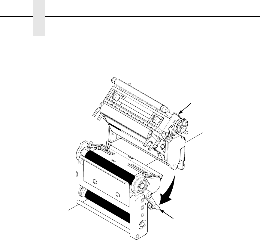
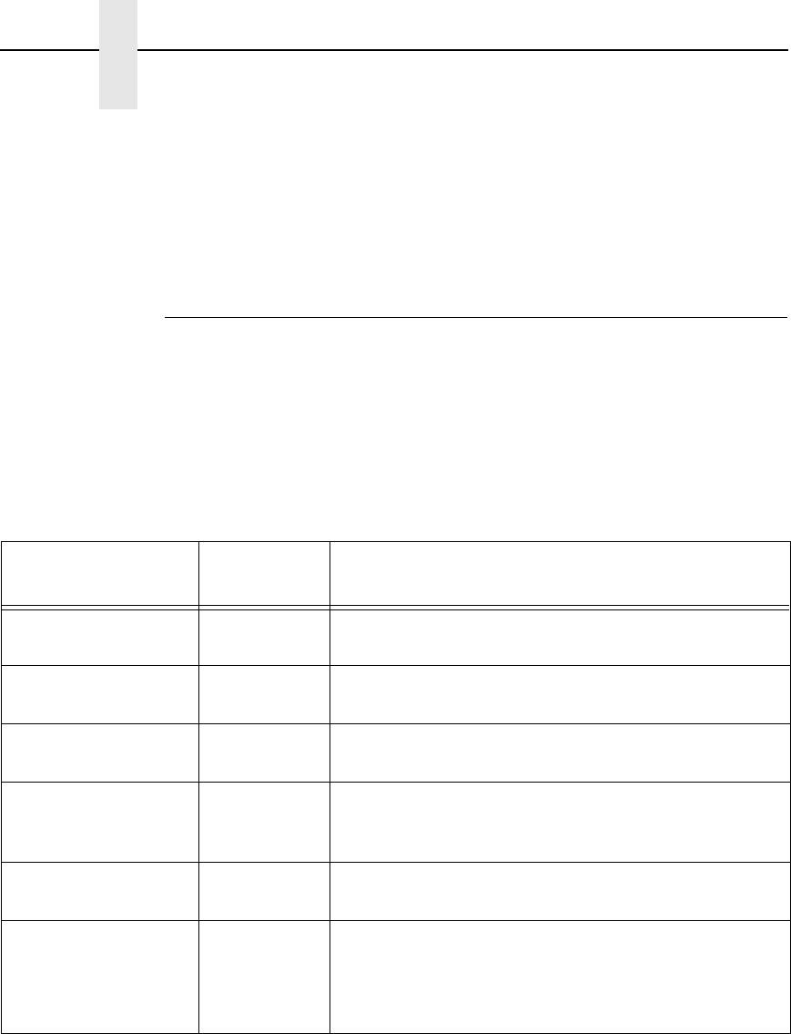
Figure 2. Mounting Label Media
3. Loosen the cam lock located on the collar of the label roll hub.
4. Slide the label roll retainer off the label roll hub.
5. Remove the empty label roll core, if necessary, from the label roll hub.
Label Roll Core
Cam Lock
Label Roll Hub
Label Roll
Retainer
Collar
Label Roll Hub
10
Chapter 1 Threading The Label Roll
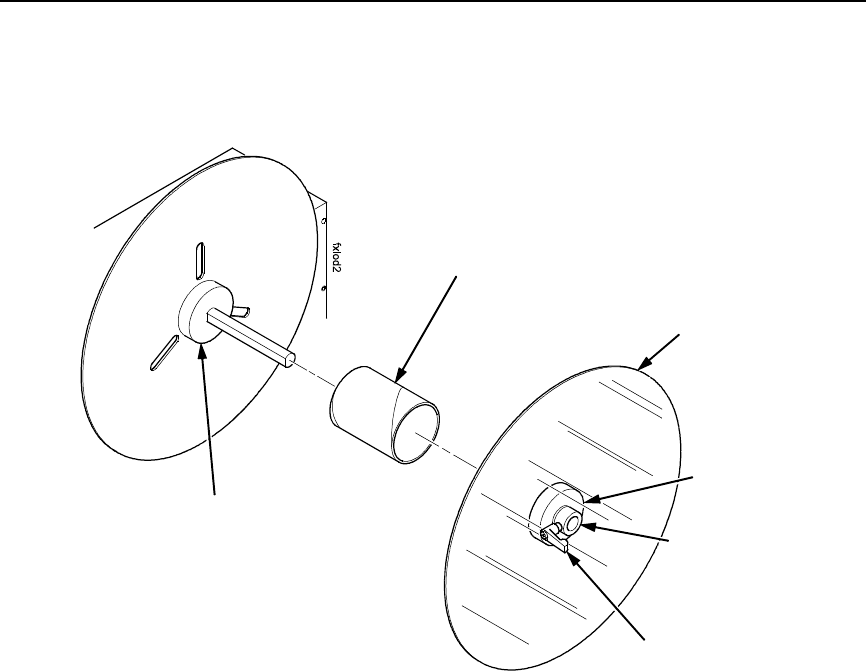
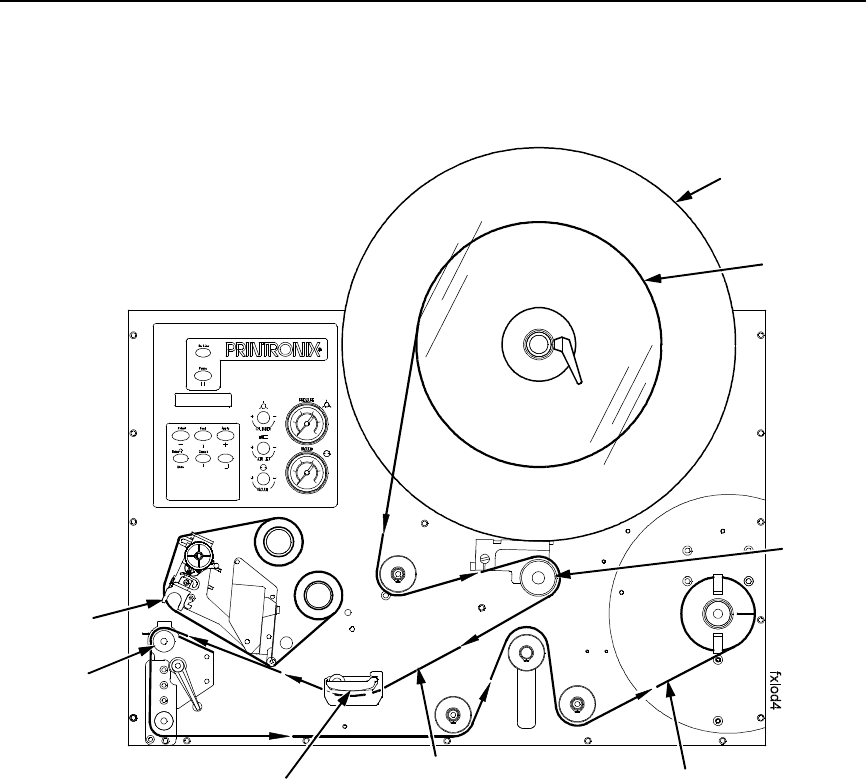
Figure 3. Loading Label Media
6. Slide the new label roll onto the label roll hub (unwinding
counterclockwise) and against the label roll back stop.
7. Angle the flat edge of the collar so that it aligns with the flat edge of the
label roll spindle.
8. Place the label roll retainer onto the label roll spindle until it is flush with
the label roll, then tighten the black cam lock.
NOTE: If necessary, loosen the set screw on the collar and adjust the core
blade so that it cuts into the label core.
Label Roll
Back Stop
Label Roll
Collar
Label Roll
Retainer
Cam Lock
Label
Label Roll
Spindle
11
Figure 4. Loading Labels
9. Unwind approximately 3.0 feet (91cm) of media from the label roll. If your
label roll does not have a leader, remove the labels from the backing. The
empty backing (leader) will act as a leader to thread the media through
the SLPA components.
10. Pull the brake assembly away from the label roll back stop (behind the
label roll retainer) to release the tension.
11. Thread the leader around the rollers and toward the media damper.
Label Roll
Retainer
Brake
Assembl
y
Printhead
Label
Platen
Media Damper Backing (Liner) Path
Label Roll
12
Chapter 1 Threading The Label Roll
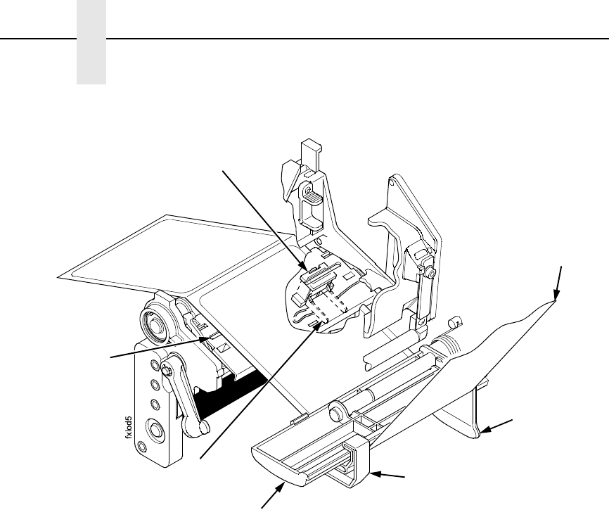
Figure 5. Threading Media Through the Printhead Assembly
12. Slide the media width guide close to the outside end of the media
damper.
13. Thread the leader under the media damper and then between the platen
(rubber drive roller) and the printhead.
14. Verify that the inside edge of the leader is against the fixed guide on the
bottom of the media damper.
15. Push the media width guide in until it is flush with the outer edge of the
media.
NOTE: Do not wrinkle the leader by pushing the media width guide too close
to the SLPA panel.
16. Check the horizontal position of the lower media sensor (located under
the media guard). Refer to “Positioning The Media Sensors” on page 50.
Media Guard
Media Width
Guide
Media Damper
Fixed Guide
Lower Media
Sensor
Media Sensor
Handle
Leader
13
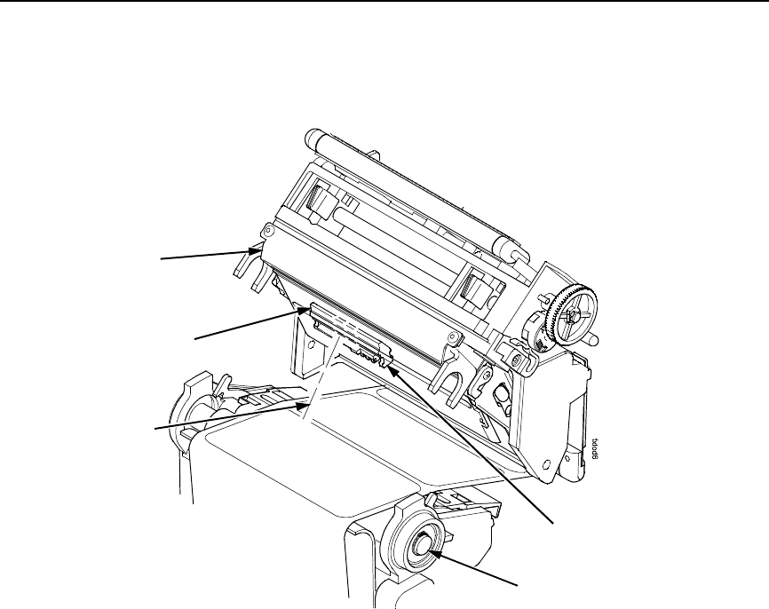
Figure 6. Threading the Leader
17. Slide the upper sensor directly over the lower sensor.
18. Thread the leader between the printhead assembly and across the top of
the platen roller.
Upper Sensor
Visible Red Beam
Lower Sensor
Upper Sensor
Handle
Platen Roller
Printhead
Assembly
14
Chapter 1 Threading The Label Roll
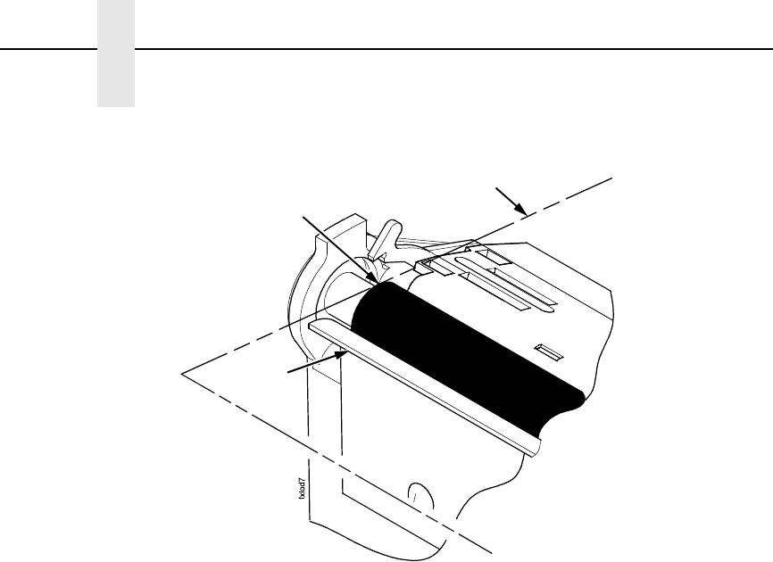
Figure 7. Aligning Media
19. Align the inside edge of the media with the inside edge of the peel bar.
20. Thread the leader over the peel bar, then between the lower print roller
and the air jet.
21. Follow the ribbon guide arrows from the printhead, around the rollers to
the media rewind spool.
22. Fold the leading edge of the leader and insert it into the slit on the rewind
spool. Make sure the leader lines up closely to the SLPA panel.
23. Manually rotate the spool at least one turn counterclockwise.
NOTE: Hold the leader down while rotating the rewind spool to keep the
leader in place.
24. If the SLPA is being used in Thermal Transfer mode, it may be necessary
to load ribbon. See “Loading Ribbon” on page 16, otherwise proceed as
follows.
Platen
Media Edge
Peel Bar
15
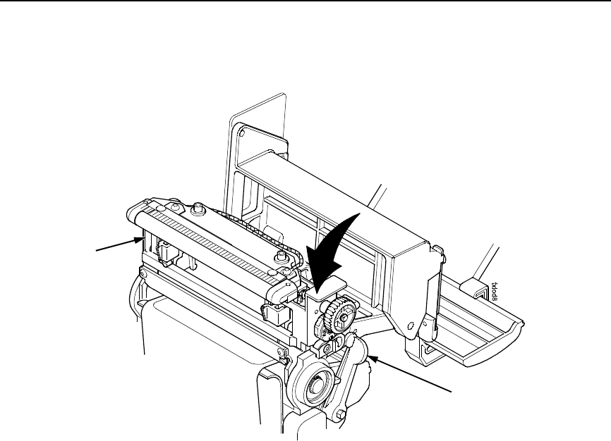
Figure 8. Locking the Pivoting Deck
25. Ensure that the label path is clear of obstructions, then close the pivoting
deck and rotate the deck lock lever fully counterclockwise. This locks the
pivoting deck and printhead assembly into the printing position.
IMPORTANT
Ensure the pivoting deck is down and locked before attempting to
advance media or print. Failure to do so will cause the PRINTHEAD UP
fault message to display.
26. Press the Pause key to place the SLPA online, and send a label format
via the host.
Pivoting Deck
Deck Lock
Lever
16
Chapter 1 Loading Ribbon
Loading Ribbon
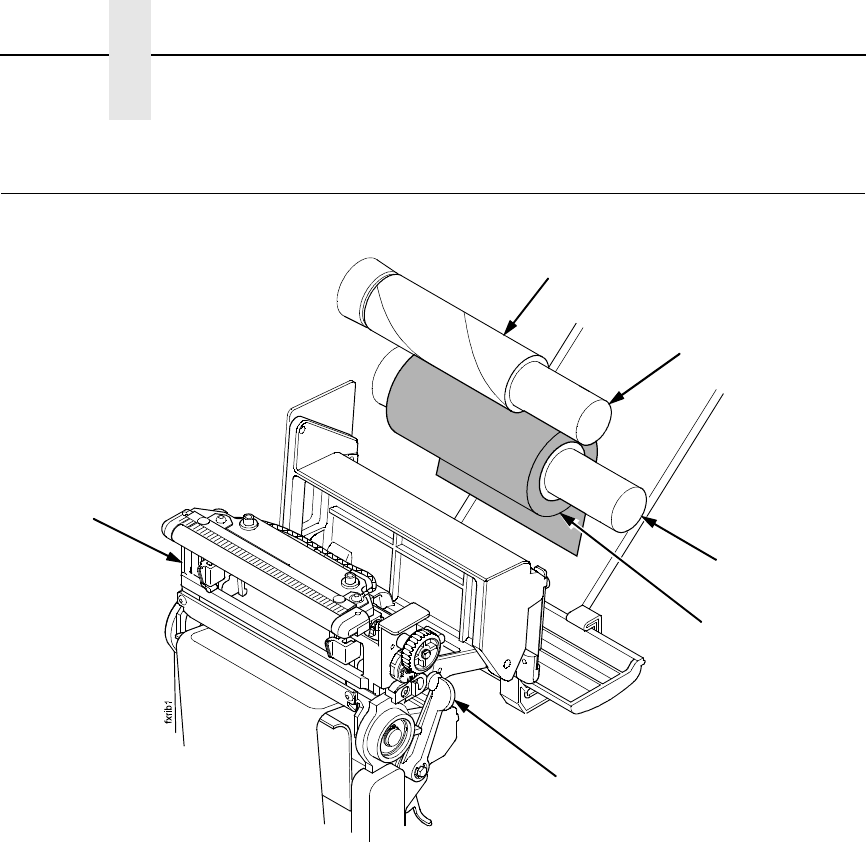
Figure 9. Loading Ribbon
1. Press the Pause key to take the SLPA offline.
2. Install the ribbon take-up core on the ribbon take-up spindle.
NOTE: The first ribbon take-up fiberboard core comes with the SLPA.
Thereafter, use the fiberboard core from the old (used up) ribbon.
3. Slide the ribbon roll onto the ribbon supply spindle until it stops against
the spindle flange.
4. Open the pivoting deck by rotating the deck lock lever fully clockwise until
the deck swings upward.
Ribbon Take-Up Core
Ribbon Take-Up
Spindle
Ribbon Supply
Spindle
Ribbon Roll
Pivoting Deck
Deck Lock Lever
17
Figure 10. Threading Ribbon Through the Printhead Assembly
5. Thread the end of the ribbon under the rear ribbon guide roller, then
between the platen and the printhead.
Ribbon
Printhead
Rear Ribbon
Guide Roller
18
Chapter 1 Loading Ribbon
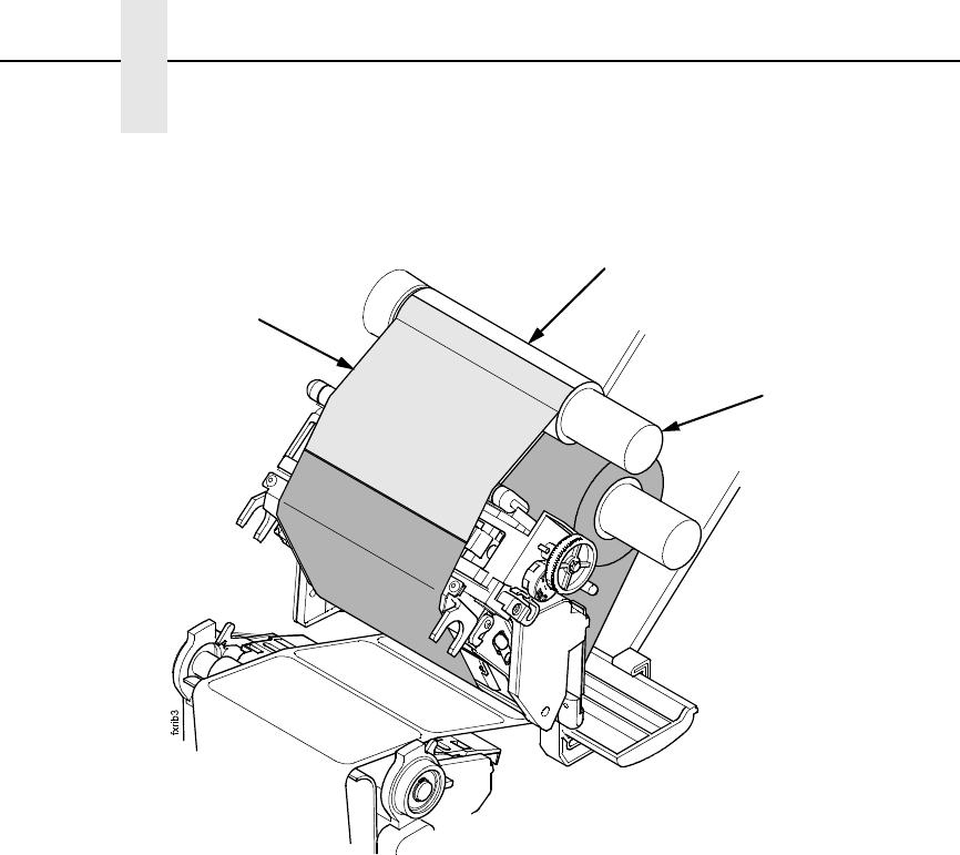
Figure 11. Attaching the Ribbon to the Take-up Core
6. Wrap the ribbon from the front of the printhead assembly to the top of the
ribbon take-up spindle. Attach the ribbon to the take-up core on the ribbon
take-up spindle with tape.
When installing a new roll of ribbon, attach the ribbon leader adhesive
strip to the ribbon take-up core. Manually rotate the spindle clockwise to
feed the unusable portion of the ribbon leader around the take-up spindle.
IMPORTANT
Do not attach the ribbon to the ribbon take-up spindle without a ribbon
take-up core installed.
7. Close the pivoting deck and rotate the deck lock lever fully clockwise.
8. Press the Feed key once to verify that the media and ribbon advance.
9. Press the Pause key to place the SLPA online, then send a label format
via the host.
Ribbon
Take-up Core
Ribbon
Take-up Spindle
Ribbon
19
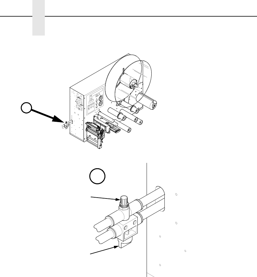
Positioning The Air Jets
When a printed label is being fed from the SLPA onto the applicator pad, it
must be held against the pad so that it can be properly positioned. The air jets
located on the air jet tube direct air at the label while it is being fed, so that it
does not bend or fall from the pad. Once proper positioning is achieved, the
vacuum of the applicator pad initiates and holds the label into place until
application.
For the air jets to work correctly, they must be directed at an angle specific to
the size of the label in use. Angle the air jets to a point which is approximately
1/3 the length of the current label length, as measured from the peel bar.
Wider or longer labels may approximate the air jet angle to a point beyond 1/3
the label length, where shorter or narrower labels may target inside the 1/3
length zone. Repeated adjustment may prove necessary for optimum
operation.
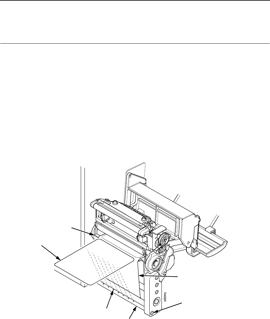
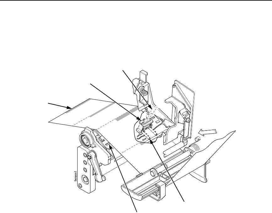
Figure 12. Positioning the Air Jets
The air jet will typically be adjusted for proper operation prior to being
shipped, but if further adjustments are necessary, proceed as follows:
1. Loosen the socket head screw holding the air tube into place.
2. Ensure that the proper holes in the air jet are open. The standard tube
comes with #2-56NC threaded holes and some of the holes may be
plugged with a small set screw. Add or remove set screws as necessary.
3. Turn the air tube adjustment so that the air jets are directed at
approximately 1/3 the length of the current label length as measured from
the peel bar.
4. Tighten the socket head screw into place to hold this adjustment.
Socket Head
Screw
Air Jet Tube
Air Jet
Label
Label Backing
Peel Bar
20
Chapter 1 Calibrating The Printer
Calibrating The Printer
For printers not using smart labels, an Auto Calibrate should be sufficient to
properly calibrate the printer (see next section).
To calibrate printers that are using smart labels:
1. Run an Auto Calibrate to set up initial values (page 21).
2. Make a Media Profile printout.
3. Make any necessary adjustments to Threshold Range in the CALIBRATE
CTRL menu.
4. Run an Auto Calibrate again (page 21).
5. Make a Media Profile printout again to verify the Threshold Range you
selected in step 3 is correct.
6. Save the configuration, and then set the saved configuration as the
Power-Up configuration (page 37).
Avoid Rounded
Die Cut Label
Corner
Position the lower
media sensor in the
grey shaded area.
Avoid Pre-Printing
FEED

Running Auto Calibrate
21
Running Auto Calibrate
IMPORTANT
Since manufacturing differences in media and ribbon can decrease the
printer’s TOF (top-of-form) sensing reliability, you must run an Auto
Calibrate to provide optimum sensor threshold values for the installed
media and ribbon.
1. Set the printer power switch to | (On).
2. Press the key to enter the QUICK SETUP menu.
NOTE: For a complete description of the QUICK SETUP menu, see page 30.
3. Press ↓ and ↵ together until ENTER SWITCH / UNLOCKED displays.
4. Press ↑ or ↓ until Label Length / 6 inch* displays (default).
5. Press + or – until the value that matches the physical length of the
installed media displays.
NOTE: Selecting the correct Label Length forces Auto Calibrate to increase
media advancement for long labels (to detect actual gaps, notches, or
marks) and decrease media advancement for short labels.
6. Press ↑ or ↓ until Gap/Mark Sensor / Disable* displays.
7. Press + or – until Gap displays.
NOTE: If you are using smart labels, see “Gap Sensing for Smart Labels” on
page 36.
8. Press ↵. An asterisk (*) displays next to the selected item.
9. Press ↓ until Auto Calibrate / Run Calibrate displays.
10. Press ↵. Media advances until it can accurately detect the label length
indicators and then stops at the top-of-form position. The Sensed
Distance value then displays for one second.
11. Auto Calibrate is successful when the Sensed Distance value correctly
matches that of the installed media. For Gap sensing, the Sensed
Distance value is the physical length of one label plus the length of one
gap.
12. If GAP NOT DETECTED or PAPER OUT displays:
a. Check the horizontal position of the media sensors.
b. Make a Media Profile printout to verify that the sensors are
performing properly.
c. Press PAUSE and run Auto Calibrate again.
13. Press the PAUSE key to take the printer offline.
14. Press the FEED key several times. Each time you press FEED, the media
should advance one label length and stop.
15. Once the Sensed Distance value and performance is confirmed, save it to
the desired configuration menu as described on page 37 before powering
off the printer.
.
.
.

22
Chapter 1 Calibrating The Printer
23
2Control Panel
The operation and system status of the SLPA are provided on the control
panel. Information concerning the SLPA is displayed on the liquid crystal
display (LCD), while commands are given to the SLPA through the control
panel keypad. Control valves are provided for refined adjustments to the
pneumatic system.
IMPORTANT
It is important to become familiar with all of the operations, readouts,
and components of the control panel. Inappropriate settings may impair
the SLPA’s functionality.
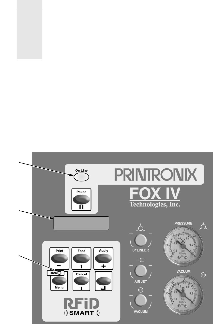
Figure 13. Control Panel
Online
Status
Indicator
Data
Indicator
Liquid
Crystal
Display
(LCD)

24
Chapter 2 LCD
LCD
The LCD is a 2 line by 16 character per line reflective display with a light
emitting diode (LED) backlight. The LCD displays system information on the
SLPA when performing system set-up procedures, print batch status during
operation, and system information in a fault condition.
Keypad
The keypad is used to place the SLPA in operation, to perform calibration or
testing, or to modify the systems operating parameters.
The keypad functions as two key groups: SLPA control when the SLPA is
online, and menu option setting when the SLPA is offline. The use of one key
group will not interfere with the use of the other key group. The function of
each indicator and key is defined in Table 1.
Table 1. Control Panel Keys
Indicator or
Key Description Online Mode Offline Mode Menu Mode
Online Status
indicator
Indicates when
SLPA is online,
offline, or in fault
condition.
Light is on when
online, ready to
print, and accept
data from host.
Flashes during
fault condition.
Light is off when
SLPA is offline.
Flashes during
fault condition.
Light is off.
Flashes during
fault condition.
Liquid Crystal
Display (LCD)
A 2 line by 16
character per
line reflective
display with a
light emitting
diode (LED)
backlight.
Displays
ONLINE, the
interface type,
and emulation in
use.
During a fault
condition,
displays specific
fault message
and required
action.
OFFLINE
During a fault
condition,
displays specific
fault message
and required
action.
Displays
OFFLINE, a
Main menu and
submenu, or
option.
During a fault
condition,
displays a
specific fault
message and
required action.
Pause key Switches the
SLPA between
online and
offline modes.
Pressing this
key when the
SLPA is online
takes the SLPA
offline.
Pressing this
key when the
SLPA is offline
places the SLPA
online.
Takes the SLPA
offline.

25
1 Cancel Key must be set to Enable in the PRINTER CONTROL menu to use
the Cancel key. The default is Disable.
Print key Print key
– (decrease) key
in Menu mode.
Prints the next
label in the
buffer.
None Scrolls left
through current
menu options.
Decreases
option values in
submenus.
Feed key Feed key
↑ (up arrow) key
in Menu mode.
Advances the
media one label
length.
None Scrolls current
menu selection
up one level.
Apply key Apply key
+ (increase) key
in Menu mode.
Prints the next
label if any and
applies the
label.
Selects the
Printer Tests
menu, and then
scrolls through
the options.
Scrolls right
through current
menu options.
Increases option
values in
submenus.
Menu key
Data indicator
Menu key
Data indicator is
green when data
is in the system.
Takes the SLPA
offline and
selects Menu
mode.
Enters Menu
mode.
Scrolls through
the Main menu
selections.
Cancel key Pressing the
Cancel key will
enable the key
and clears all
data from the
print buffer and
prevent printing
of that data.1
↓ (down arrow)
key in Menu
mode.
None Clears all data in
the print buffer.
Scrolls the
current menu
selection down
one level.
↵ (Enter) key Pressing the ↵
(Enter) key in
Menu mode
selects the
displayed option
or value.
Selects the
Applicator Delay
menu (page 95).
When in the
Printer Tests
menu, runs the
selected test.
Selects the
current menu
value.
Table 1. Control Panel Keys
Indicator or
Key Description Online Mode Offline Mode Menu Mode

26
Chapter 2 Key and Indicator Descriptions
Key and Indicator Descriptions
For the locations of these keys and indicators, refer to Figure 13 on page 23.
Online Status Indicator
The SLPA is online when the Online status indicator light is on. When the
SLPA is offline, the light is off.
Pause Key
When the SLPA is online or in Menu mode, the Pause key takes the SLPA
offline (offline mode) and suspends all SLPA operations, but operations do
not cease until the current print or apply cycles have been completed. When
the SLPA is offline, the operator may make mechanical adjustments to the
SLPA, clear assembly line jams, etc., without powering off the system.
When the SLPA is offline, the Pause key places the SLPA back online (online
mode).
NOTE: The SLPA may automatically take itself offline in several situations
(e.g., out of labels, after recovering from a fault, etc.).
Print Key
When the SLPA is online, the Print key prints a label and feeds it to the
applicator pad if there is a label configuration in the SLPA’s print buffer. If no
label pattern exists in the buffer, it will not function.
In Menu mode, the – (decrease) key scrolls left through current menu options
or decreases option values in submenus.
NOTE: The Print key has no effect when the SLPA is offline.
Feed Key
When the SLPA is online, the Feed key advances the media one label length.
if the print buffer is currently empty. If the system is printing labels from the
buffer, this key will not function until the batch is done printing.
In Menu mode, the ↑ (up arrow) key scrolls the current menu selection one
level up.
NOTE: The Feed key has no effect when the SLPA is offline.
Apply Key
When the SLPA is online, the Apply key cycles the applicator as though the
SLPA was triggered by the product sensor. The cylinder extends to place the
label and a new label prints and is placed on the pad upon its return to the
home position.
In Menu mode, the + (increase) key scrolls right through current menu options
or increases option values in submenus.

27
Menu Key and Data Indicator Light
When the SLPA is either online or offline, the Menu key takes the SLPA
offline and into Menu mode.
In Menu mode, the Menu key scrolls through the Main menu of the SLPA’s
operating system. It permits the operator to set or change various operating
parameters.
The Data indicator light on the Menu key is green when data is in the system.
This data refers to the information printed on the label. If the green light is off,
there is no data in the system. There is no manual operation of this indicator.
Cancel Key
NOTE: Cancel Key must be set to Enable in the PRINTER CONTROL menu
to use the Cancel key. The default is Disable.
When the SLPA is offline, the Cancel key clears the current print pattern and
all printing programs currently in the print buffer.
After clearing the print buffer, the SLPA automatically takes itself offline. The
SLPA may then have a new label pattern downloaded to the print buffer.
Press the Pause key to place the SLPA back online.
In Menu mode, the ↓ (down arrow) key scrolls the current menu selection one
level down.
NOTE: The Print key has no effect when the SLPA is online.
↵
(Enter Key)
When the SLPA is online, the ↵ (Enter) key selects the Applicator Display
Menu (page 95).
When the SLPA is offline, the ↵ (Enter) key is used to select a menu option,
or parameter value within the submenus. Press ↵ to select a menu option or
parameter.
In Menu mode, the ↵ (Enter) key selects the current value.
28
Chapter 2 Pneumatic Control Valves And Gauges
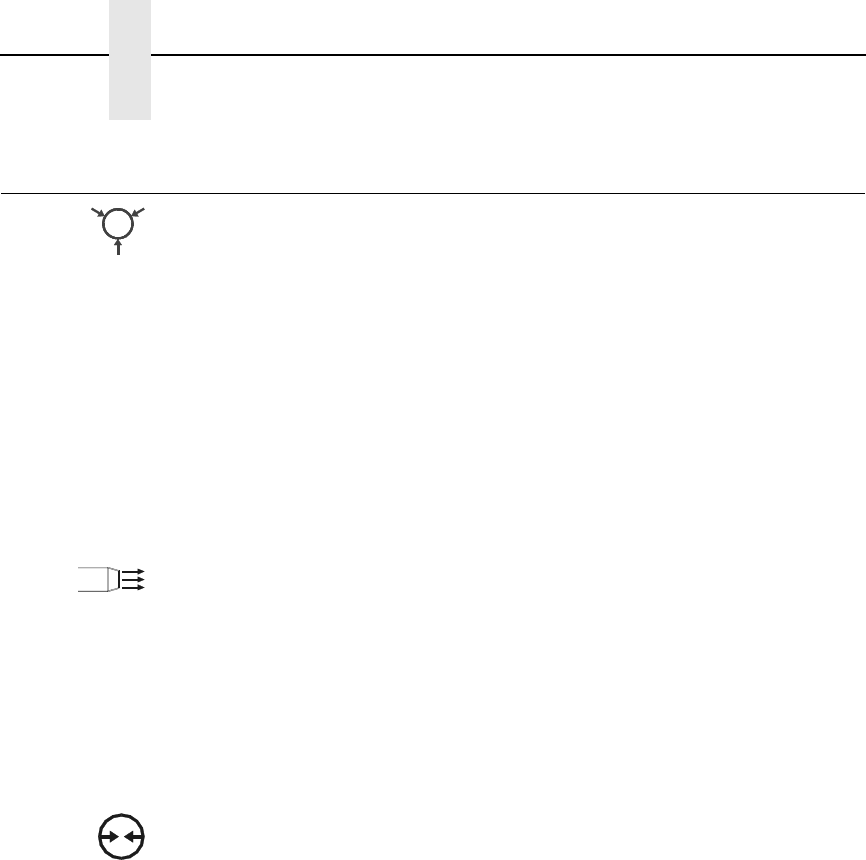
Pneumatic Control Valves And Gauges
Air Cylinder Regulator
NOTE: You may also adjust the cylinder delay time through the Applicator
Delay menu. See “Applicator Delay Menu” on page 29.
The air cylinder regulator (CYLINDER valve) is used to regulate the air to the
applicator cylinder. The regulator setting affects how quickly the applicator
pad will extend (apply stroke) and return (return stroke) during the apply
cycle. This adjustment determines the force with which the applicator pad will
contact the product. If set too high, the applicator pad could contact the
product with enough force to cause damage. If set too low, the applicator pad
may not contact the product. The air pressure delivered for the apply stroke
and the return stroke is equal.
Monitor the setting of the air cylinder regulator using the PRESSURE gauge.
Air Jet Adjustment
The air jet adjustment (AIR JET) controls the air supply to the air jet tube. Air
is forced out the air jet tube allowing the labels to properly transfer over the
peel bar then to the applicator pad. If the adjustment is too low, the labels will
not properly transfer from the printer to the applicator pad. If set too high, the
label edge will be incorrectly positioned. The air jet is factory preset. Adjust
the air jet pressure by turning the AIR JET control clockwise to increase the
flow, counterclockwise to decrease the flow. See “Positioning The Air Jets” on
page 19.
Vacuum Adjustment
NOTE: You may also adjust the vacuum delay time through the Applicator
Delay Menu. See “Applicator Delay Menu” on page 29.
The vacuum adjustment (VACUUM) controls the amount of air flow through
the vacuum generator, thus determining the amount of vacuum holding the
label onto the applicator pad. A weak vacuum will cause labels to fall off of the
applicator pad prematurely. A vacuum that is too strong, however, can cause
difficulty when transferring the label onto the applicator pad and the product.
Vacuum is increased by rotating the valve clockwise and decreased by
rotating the valve counterclockwise.
NOTE: To get a vacuum on every label, every hole on the applicator pad
must be covered by the label surface.
Monitor the setting of the vacuum adjustment using the VACUUM gauge.

29
Applicator Delay Menu
With the SLPA online, press the ↵ key to enter the Applicator Delay menu.
Press ↑ or ↓ to scroll through the submenus: Cycle Delay, Cylinder Extend,
and Vacuum Delay. Press + or – to adjust the values. Press ↵ to set a new
value.
Press the Menu key to place the SLPA back online. SAVING / DELAY TIMES
will display briefly.
Cycle Delay
Sets the length of time the product sensor detects the product until it applies
the label.
Cylinder Extend
Sets the length of elapsed time from the beginning of the cylinder extension to
its retraction.
Dancer Time
Sets the length of time the dance stays down to prevent a failed label tag from
being peeled.
30
Chapter 2 QUICK SETUP Menu
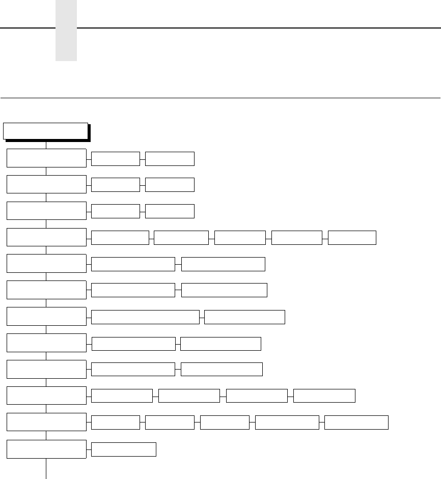
QUICK SETUP Menu
(cont. on next page)
QUICK SETUP
Print Intensity
Transfer* Direct
Print Mode 2
Paper Feed Shift
Label Width
Label Length
Orientation
4.1, 6.6, or 8.5 inches* 3, 5
Portrait* Landscape Inv. Portrait Inv. Landscape
–3* –15 to 15
00.1 to 8.5 inches 5
0.00 inches* 3
4 or 6 inches* 3, 5 00.1 to 99.0 inches 6
–0.50 to
X
inches 4
Run Calibrate
Auto Calibrate
Ver Image Shift
Hor Image Shift
0.00 inches* 3
–1.00 to 1.00 inches 0.00 inches* 3
–1.00 to
X
inches 4
Tear-Off Strip* Tear-Off Peel-Off Cut
Media Handling Continuous
Gap/Mark Sensor Disable* Mark Gap Advanced NotchAdvanced Gap
Notes:
* = Default
1 Maximum value depends on the width of the
printer model and printhead.
2 Does not appear for direct thermal only printers.
3 You can change the unit value from inches to
millimeters under Units (in MEDIA CONTROL)
See the
User’s Manual
for information.
4 Based on the current value setting for the Label
Length menu, up to a maximum of 12.80 inches.
5 Maximum value depends on the width of the
printer model.
6 Maximum value depends on model width and size
of DRAM installed.
6 ips* 2 to 10 ips 1
Print Speed
QUICK SETUP Menu Items
31
NOTE: Many QUICK SETUP menu items are available in other main menus.
(Refer to the
User’s Manual
.)
Changes made in the QUICK SETUP menu are updated in the other
main menus, and vice versa.
QUICK SETUP Menu Items
Print Intensity
This menu item specifies the level of thermal energy from the printhead to be
used for the type of media and ribbon installed.
Large numbers imply more heat (thermal energy) to be applied for each dot.
This has a significant effect on print quality. The print intensity and speed
must match the media and ribbon type to obtain the best possible print quality
and barcode grades.
The range is –15 through +15. The default is –3.
Print Speed
This menu item specifies the speed in inches per second (ips) at which the
media passes through the printer while printing.
The range is 2 through 10 ips (in increments of 1 ips).
The default is 6 ips.
NOTE: The maximum print speed varies based on maximum printer width
and dot per inch (dpi) resolution of the printhead installed (203 or 300
dpi).
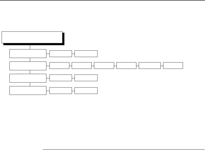
1* 1 to 8
Factory* 1 to 8
Save Config.
Power-Up Config.
IGP/PGL* PPI/ZGL 2
Active IGP Emul PPI/TGL 2PPI/IGL 2IGP/VGL
QUICK SETUP
(cont. from previous page)
PPI/STGL 2
Validator Funct. 1Enable* Disable

32
Chapter 2 QUICK SETUP Menu
Print Mode
This menu item specifies the type of printing to be done.
•Transfer. Indicates thermal transfer printing (ribbon installed).
•Direct. Indicates direct thermal printing (no ribbon) and requires special
heat sensitive media.
The default is Transfer, unless your printer is shipped as direct thermal only
(no ribbon motors installed).
NOTE: The Print Mode menu item does not appear for direct thermal only
printers.
Media Handling
This menu item specifies how the printer will handle the media (labels or tag
stock).
•Tear-Off Strip. Printer prints on the media and sends it out the front until
the print buffer is empty, then positions the last label over the tear bar for
removal.
•Tear-Off. After each label is printed, the printer positions the label over
the tear bar and waits for you to tear off the label before printing the next
one (on-demand printing). A “Remove Label” message displays to remind
you to remove the label before the next one can be printed.
•Peel-Off. When the optional rewinder is installed, prints and peels die cut
labels from the liner without assistance. The printer waits for you to
remove the label before printing the next one (on-demand printing). The
label liner is rewound on the internal rewinder. A “Remove Label”
message displays to remind you to remove the label before the next one
can be printed.
•Cut. When the optional media cutter is installed, it automatically cuts
media after each label is printed or can cut after a specified number of
labels have been printed using a software cut command. It cuts
continuous roll paper, labels, or tag stock.
NOTE: The Cut option is hidden when RFID Reader is set to Enable in the
RFID CONTROL menu.
•Continuous. Printer prints on the media and sends it out the front.
The default is Tear-Off Strip.
Paper Feed Shift
This menu item represents the distance to advance a label (+ shift) or pull
back (– shift) when the Tear-Off Strip, Tear-Off, Peel-Off, or Cut Media
Handling option is enabled. The allowable range is –0.50 inches to the current
Label Length value setting up to a maximum of 12.80 inches in 0.01 inch
increments.
The default is 0.00 inches.

QUICK SETUP Menu Items
33
Label Length
In most applications, the user-selected Label Length will match the physical
label length. Physical label length is the actual label length of the media
installed. Following is a list of different media types:
•Die cut labels: measurable length of the removable label (leading
edge to trailing edge). This does not include the liner material or gap.
•Tag stock with notches or holes: measurable length from the trailing
edge of one notch or hole to the trailing edge of the next notch or
hole.
•Tag stock with black marks on the underside: measurable length from
the leading edge of one black mark to the leading edge of the next
black mark.
•Continuous media (no label length indicators): measurable length
should be within + 1 to 2% of the Label Length value entered.
Label Width
This menu item specifies the label width. The allowable range in inches is
00.1 to the maximum print width of the printer. The allowable range in
millimeters is 2.5 to the maximum width of the printer.
Ver Image Shift
This menu item specifies the amount to shift an image up (–) or down (+) for
precise positioning on the label. The actual height of the image is not affected
by this parameter. The allowable range is –1.00 inches to the current Label
Length value setting, up to a maximum of 12.80 inches, in 0.01 inch
increments.
The default value is 0.00 inches.
Hor Image Shift
This menu item specifies the amount to shift an image left (–) or right (+) for
precise positioning on the label. The actual width of the image is not affected
by this parameter. The allowable range is
–1.00 to +1.00 inches in 0.01 inch increments.
The default value is 0.00 inches.
Orientation
Specifies the image orientation to be used when printing the label.
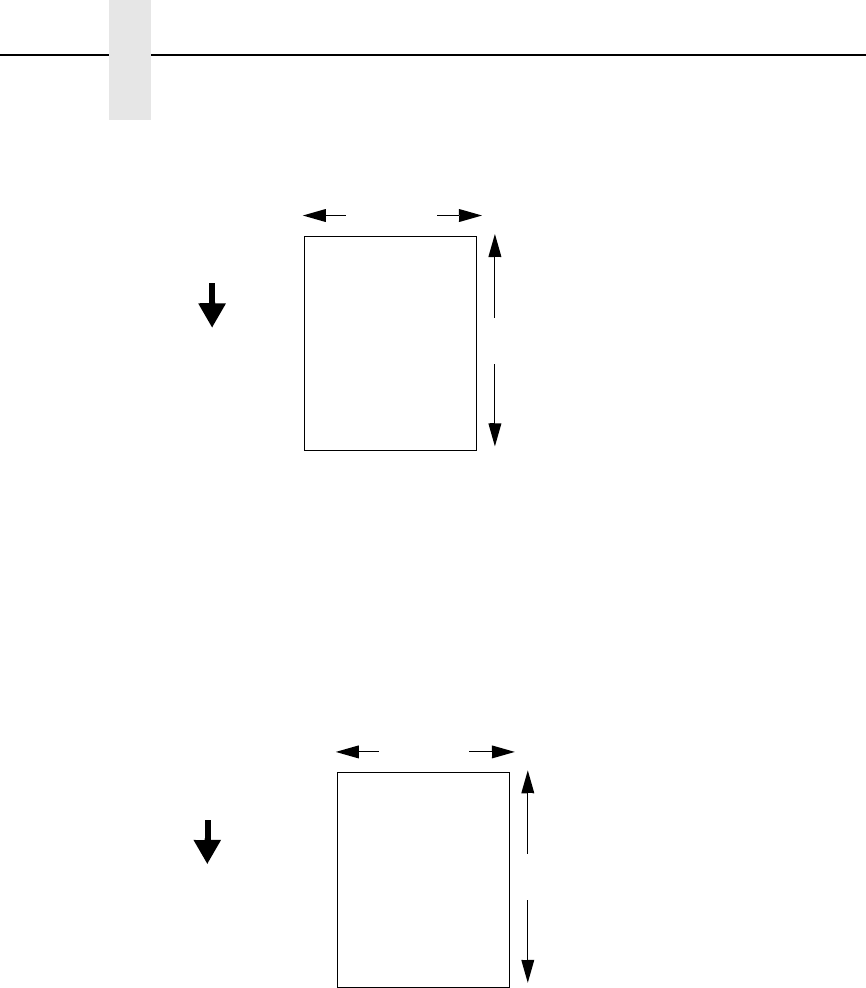
•Portrait. The default. Portrait refers to vertical page orientation, where the
height of a page is greater than its width. The top edge of the image is
parallel to the leading edge of the media. The following example is viewed
from the front of the printer.
NOTE: Portrait orientation applies to PGL® and VGL emulations. This is
regarded as Inverse Portrait using PPI/ZGL.
34
Chapter 2 QUICK SETUP Menu
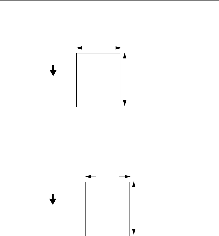
•Landscape. Landscape refers to horizontal orientation, where the width
of a page is greater than its height. The top edge of the image is parallel
to the left edge of the media. The following example is viewed from the
front of the printer.
NOTE: Landscape orientation applies to PGL and VGL emulations. This is
regarded as Inverse Landscape using PPI/ZGL.
•Inv. Portrait. Inverse Portrait refers to vertical page orientation, where the
height of a page is greater than its width. The top edge of the image is
parallel to the trailing edge of the media. The following example is viewed
from the front of the printer.
NOTE: Inverse Portrait orientation applies to PGL and VGL emulations. This
is regarded as Portrait using PPI/ZGL.
4 inches
FEED
6 inches
The top edge of
the image is
parallel to the
leading edge of
the media.
Leading Edge
4 inches
FEED
6 inches
The top edge of
the image is
parallel to the left
edge of the media.
Leading Edge
QUICK SETUP Menu Items
35
•Inv. Landscape. Inverse Landscape refers to horizontal orientation,
where the width of a page is greater than its height. The top edge of the
image is parallel to the right edge of the media. The following example is
viewed from the front of the printer.
NOTE: Inverse Landscape orientation applies to PGL and VGL emulations.
This is regarded as Landscape using PPI/ZGL.
Gap/Mark Sensor
Specifies the sensor type needed for detecting the top-of-form position on
media with label length indicators (gaps, notches, holes, or black marks).
•Disable. Select when using media with no label length indicators (no
gaps, notches, holes, or black marks), or
when you want the printer to
ignore all existing label length indicators on the installed media.
NOTE: When you select Disable, the length of each label is based on the
Label Length value entered.
•Mark. Select when using media that has horizontal black marks located
on the underside of the label liner or tag stock. The
top-of-form position is the leading edge of the black mark.
4 inches
FEED
6 inches
The top edge of
the image is
parallel to the
trailing edge of the
media.
Leading Edge
Trailing Edge
4 inches
FEED
6 inches
The top edge of
the image is
parallel to the right
edge of the media.
Leading Edge

36
Chapter 2 QUICK SETUP Menu
•Gap. Select
when using media with a liner space between
die cut labels or when using tag stock with notches or holes as label
length indicators on white background media. The
top-of-form position is the leading edge of the die cut label (trailing edge
of the gap, notch, or hole).
•Advanced Gap. Select when using media that has liner gaps between
die cut labels with black background. The top-of-form position is the
leading edge of the die cut label (trailing edge of the gap, notch, or hole).
•Advanced Notch. Select when using media with notches or holes that
interrupt a black vertical line on the underside of the media. The top-of-
form position is the leading edge of the die cut label (trailing edge of the
gap, notch, or hole).
The default is Disable.
Gap Sensing for Smart Labels
If your smart labels have a horizontal black bar located within each liner gap,
set Gap/Mark Sensor to Gap. When you examine a Media Profile printout,
you will see that the black bar provides a much higher amplitude pulse than
that of any antenna, which will provide excellent top-of-form reliability.
If your smart labels have no horizontal black bar located within each liner gap,
you must choose between Gap and Advanced Gap sensing. Run an Auto
Calibrate (page 21), then make a Media Profile printout. Choose the sensing
type that provides the highest liner gap amplitude compared to the amplitude
of the antenna line. If you select Gap sensing, and then see that the Media
Profile printout shows very little amplitude difference for the liner gap
compared to the amplitude of the antenna line, select Advanced Gap sensing
instead.
Advanced Gap sensing (often called transmissive) uses an LED array for the
upper sensor and a receiver in the lower sensor to detect infrared light
through the liner gap. This sensing has the advantage of detecting the liner
gap as a positive amplitude pulse and the antenna line as a smaller, negative
pulse.
Save Config.
Allows you to save up to eight unique configurations to meet different print job
requirements. This eliminates the need to change the parameter settings for
each new job. The configurations are stored in memory and will not be lost if
you turn off the printer.
The default is 1.
Power-Up Config.
You can specify the Factory configuration or any one of the eight possible
saved configurations as the power-up configuration.
The default is Factory.

QUICK SETUP Menu Items
37
Saving The Configuration
After customizing your settings, save them as a configuration:
1. Press the key to enter the QUICK SETUP menu.
2. Press ↑ or ↓ until Save Config. / 1* displays.
3. If necessary, press + or – until the desired configuration displays.
4. Press ↵. Saving Configuration displays briefly.
NOTE:
You can specify a 15-character name for your configuration. See
“Name Config (1-8)” in the
User’s Manual
.
5. If necessary, set your newly saved configuration as the Power-Up
configuration. See “Selecting The Power-Up Configuration” below.
Selecting The Power-Up Configuration
To have a saved configuration automatically loaded when you power up the
printer, set the saved configuration as the Power-Up configuration:
1. Press the key to enter the QUICK SETUP menu.
2. Press ↑ or ↓ until Power-Up Config. / Factory* displays.
3. Press + or – until the desired configuration displays.
4. Press ↵. An asterisk (*) displays next to the selected configuration.
Loading A Saved Configuration
To use a different configuration, load a saved configuration:
1. Press the PAUSE key until OFFLINE displays.
2. Press the JOB SELECT key until the desired configuration displays.
3. Press ↵. Loading Saved / Configuration displays.
WARNING
Prior to any maintenance procedures, be sure to power off the SLPA
and disconnect the power cord and air supply hoses unless otherwise
indicated.
WARNING
Maintenance operation should only be performed by a trained and
qualified technician.
.
.
.
.
.
.

38
Chapter 2 Loading A Saved Configuration

39
3Printing And Applying
Labels
Printing And Applying Labels
WARNING
Printronix has provided the necessary guards and warnings within the
confines of the SLPA, but cannot anticipate each customer’s individual
installation and operational environments. It is the customer’s
responsibility to provide in-house safety guards to provide adequate
worker safety for their respective production settings.
WARNING
An input signal from the product sensor will activate the SLPA when the
SLPA is online unless it is taken offline.
This section provides a brief overview of the print and apply process as well
as suggested steps preliminary to printing.
During power-up, the SLPA performs a self-diagnostic test and indicates if the
system has any existing fault or warning conditions.
Once the SLPA is online and configured (if necessary) for the desired
application, take the SLPA offline before downloading labels from the host
into the buffer. This will prevent any chance of having the system cycle before
you are prepared to begin print operations.
For information on the proper setup of the SLPA, see “Setup Procedures” on
page 7.
Label Application (Positioning) Adjustments
To apply the labels at the desired location on the product:
1. Mount the product sensor on the side of the conveyor, determining if the
sensor should be mounted upstream from the applicator pad (product
passes sensor before pad) or downstream from the applicator pad
(product passes pad before sensor), depending on the application.
IMPORTANT
Mount the product sensor as close as possible to the applicator pad. If
the spacing between the two is too wide, it may be to difficult to set the
product sensor delay to position the label properly.
It is easier to position the label onto the product using the sensor delay
when the sensor is mounted upstream from the applicator pad.
40
Chapter 3 Printing And Applying Labels
Figure 14. Return Speed Control Valve
2. Use the flow control valve (located on the air cylinder) to adjust the speed
of the return stroke. (Figure 14.) Increase the speed by rotating the valve
counterclockwise and decrease the speed by rotating the valve
clockwise.
3. Set the Cycle Delay time for the product sensor using the Applicator
Delay menu. (See “Applicator Delay Menu” on page 95.)
NOTE: The Cycle Delay setting determines the amount of delay from the
time that the product sensor detects the product to the time that the
applicator pad is online. Since the label prints first, be sure to account
for printing time. The longer the time entered, the farther back (closer
to the trailing edge) the label will be placed onto the product.
Conversely, if this value is set to zero, for example, the applicator pad
will launch as soon as the label is printed.
Begin by setting the Cylinder Extend time to 100 msec to begin this
adjustment procedure. (See “Applicator Delay Menu” on page 95.)
A
A
Flow Control
Valve
Air Shut Off
Valve

Adjusting The Cylinder Extend Time
41
4. Place the product sample on the conveyor and allow it move past the
SLPA. The label that is applied will be used as a reference point for
positioning the rest of the labels.
5. To move the label toward the leading edge of the product, decrease the
Cycle Delay time. Begin by decreasing the time in intervals of 10 msec,
then fine tune in intervals 1 msec. Repeat this procedure until the label is
positioned where desired.
6. To move the label toward the trailing edge of the product, increase the
Cycle Delay time. Begin by increasing the time in intervals of 10 msec,
then fine tune in intervals 1 msec. Repeat this procedure until the label is
positioned where desired.
If the label still cannot be positioned properly, remount the product sensor as
follows:
1. To position the label toward the leading edge of the product, move the
product sensor upstream.
2. To position the label toward the trailing edge of the product, move the
product sensor downstream.
3. Once the label is positioned in the desired location on the product, secure
the product sensor onto the conveyor.
If the SLPA cycles when a product is not in position, a background object may
be activating the sensor. To correct this problem, reposition the product
sensor or adjust the product sensor. See “Product Sensor” on page 197 for
more information on product sensor adjustments.
WARNING
Interrupting the signal on the product sensor will activate the SLPA.
Make certain that the path of the applicator path is clear.
Adjusting The Cylinder Extend Time
NOTE: Remember that the supply air pressure to the SLPA should be
80 to 100 psi (550 to 690 kPa).
1. Set the Cylinder Extend time using the Applicator Delay menu.
(“Applicator Delay Menu” on page 29.)
NOTE: The amount of time the applicator pad is energized through the
cylinder extend time, determines how far the pad travels during
application of the label. The longer the time entered, the farther the
distance the applicator pad travels. If this value is set to zero, for
example, the applicator pad will not launch.
Set the Cylinder Extend time to 110 msec to begin this adjustment
procedure.
•If the applicator pad does not contact the product (if the stroke time is not
long enough):
Increase the Cylinder Extend time using the Applicator Delay menu.
Begin by increasing the time in intervals of 6 msec, then fine tune in
increments of 1 msec. A higher setting allows the applicator pad more
time to extend toward the product, therefore, increasing the stroke
length.

42
Chapter 3 Printing And Applying Labels
•If the applicator pad remains on the product for too long (if the stroke time
is too long):
Decrease the Cylinder Extend time using the Applicator Delay menu.
Begin by increasing the time in intervals of 6 msec, then fine tune in
increments of 1 msec. A lower setting decreases the amount of time
that the applicator pad is extended (in contact with the product).
The Print And Apply Process
Before labels can be printed and applied:
1. Ensure that the protective guards are properly secured and that materials
are clear of the applicator pad and printhead assembly.
2. Ensure that you have input time values for Cycle Delay, Cylinder Extend,
and Vacuum Delay (if applicable). (See “Applicator Delay Menu” on
page 95.)
NOTE: The applicator will not move unless a value is entered for Cylinder
Extend.
3. Press the Pause key on the control panel to enable the product sensor, or
to allow remote signals received through the interface package option to
activate the SLPA.
NOTE: You may wish to cycle several labels onto product samples, to ensure
proper operation of the SLPA.

43
4Preventive Maintenance
And Cleaning
WARNING
Prior to any maintenance procedures, be sure to power off the SLPA
and disconnect the power cord and air supply hoses unless otherwise
indicated.
WARNING
Maintenance operation should only be performed by a trained and
qualified technician.
Cleaning
General Cleaning
During normal operation, media debris may accumulate around the printer
mechanism. Clean the printhead area with the Printronix cleaning kit. Use a
soft bristle brush or vacuum cleaner to dust the interior.
CAUTION
Never use metallic tools to clean the interior of the SLPA.
Dust the exterior of the SLPA regularly. It is preferable to use a Printronix
cleaning kit to clean the exterior of the SLPA, or a soft cloth dampened with
isopropyl alcohol.
CAUTION
Do not use abrasive cleaners or solvents to clean either the exterior or
interior of the SLPA.
44
Chapter 4 Cleaning
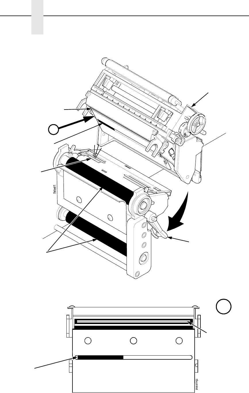
Figure 15. Cleaning the Printhead
Pivoting Deck
Deck Lock
Lever
Printhead
Heating
Elements
Lower Media
Sensor
Printhead Cover/
Upper Media Sensor
(not visible)
Platen Rollers
A
A
Upper
Sensor
Print Element

Cleaning The Printhead, Platen Roller And Media Sensors
45
Cleaning The Printhead, Platen Roller And Media
Sensors
Printhead Cleaning
As you use your SLPA, the printhead may become dirty which can result in
poor print quality. Clean the printhead each time you install new ribbon
(thermal transfer print mode) or install new media (direct thermal print mode).
Clean the printhead with the cleaning pen supplied with the SLPA or with a
cotton swab moistened with alcohol.
By keeping your printhead clean, you will help maintain its life.
Platen Rollers Cleaning
Media dust and adhesive residue on the platen roller can degrade print quality
and cause voids in your label image. Clean the platen rollers at the same time
as the printhead. See Figure 15 on page 44.
Use a small amount of isopropyl alcohol on a cloth to clean the platen roller.
With the pivoting deck up the platen roller can be rotated forward by hand to
access and clean its entire surface area.
Media Sensor Cleaning
The Upper and Lower Media Sensors should be cleaned to ensure reliable
TOF and paper out sensing. Clean the media sensors at the same time as the
printhead.
The Upper Media Sensor (located in the horizontal slot of the printhead cover)
can be wiped clean using a soft cloth. The Lower Media Sensor, easily seen
by its visible red light, is located in the horizontal slot of the media guard.
Remove media dust by vacuuming or blowing air across the lens cover.
Cleaning Procedure
1. Set the power switch to O (Off) and let the SLPA cool for 5 minutes.
2. Rotate the deck lock lever clockwise to open the pivoting deck and
remove any media and ribbon (if loaded) to gain access to the printhead
assembly heating element area.
3. Gently rub the felt tip of the cleaning pen or a cotton swab moistened with
isopropyl alcohol across the printhead heating elements (light brown
area).
4. Allow the printhead to dry for one minute before reloading the media and
ribbon.
5. Clean the platen roller.
6. Clean the upper and lower media sensors.
CAUTION
Do not use sharp objects on the print surface of the printhead. Be aware
that the edges of the printhead may be sharp. Keep fingers away from
the edges.
46
Chapter 4 Cleaning
Cleaning The Applicator Pad
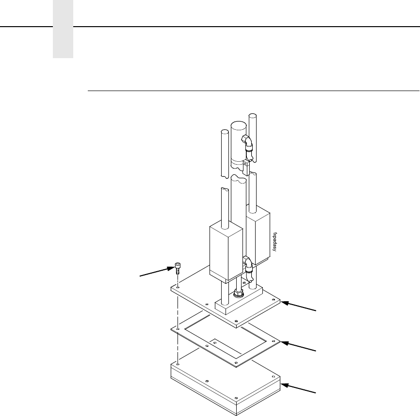
Figure 16. The Applicator Pad Assembly
The applicator pad must be clean to ensure that labels will properly dispense.
Use isopropyl alcohol and a clean soft cloth. No other cleaning agent should
be used to clean the applicator pad.
Perform a maintenance check of the applicator pad vacuum chamber
approximately every three months, at minimum, using the following
procedures:
1. Remove the four (or six) hex screws found at the top of the applicator
pad, allowing the bottom pad to drop downward.
2. Check the holes of the applicator pad to make certain that there are no
large particles of dirt or dust clogging any of the holes.
3. Reassemble, making certain that the gasket (foam tape) is seated
properly before replacing the bottom pad.
4. Check for leaks by covering all the holes in the applicator pad with a piece
of paper. If there is a leak, the vacuum will not retain the paper on
underside of the applicator. Sealing compound may be used to isolate
leaks, but must dry thoroughly before the applicator may be used.
Hex Screw (4 or 6)
Top Pad
Gasket
Bottom Pad
Cleaning/Replacing The Vacuum Generator
47
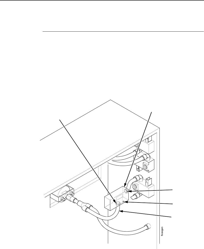
Cleaning/Replacing The Vacuum Generator
Air flow through the vacuum generator creates the vacuum for the applicator
pad, allowing the label to be held in place. If the label is not retained on the
pad and the pad has already been inspected for leaks, then the vacuum
generator should be cleaned as follows.
1. Locate the vacuum generator inside the electrical enclosure, on the
applicator side of the SLPA (see Figure 17). The vacuum generator
housing will mark the pressure connection with a P and the vacuum
connection with a V. Label the respective tubes before disconnecting
them, to ensure proper reassembly.
Figure 17. Vacuum Generator
2. Remove the two air lines attached to the vacuum generator by pushing in
on the tube fitting (red collar) to release tension on the flexible tubing.
Hold the tube fitting down while pulling the tube free.
3. Carefully wipe inside the tube fittings, using a small cotton swab
moistened with alcohol.
4. Using a low pressure air nozzle (90 psi. max. pressure) blow air through
the V port, then the P port using three - 2 second bursts.
5. Reconnect the vacuum generator and test the applicator pad’s vacuum as
outlined in “Cleaning The Applicator Pad” on page 46.
Vacuum
Generator
Air Line (2)
Tube Fitting (2)
V Port
P Port
48
Chapter 4 Cleaning
6. Check the inline vaccum filter located between the Tamp and SLPA.
Replace if necessary.
7. If the vacuum has not improved and all pneumatic assemblies and tubing
are secure, replace the vacuum generator being careful to connect the air
lines to the proper fitting.
Cleaning Schedule
WARNING
All cleaning of printer/applicator parts should be done with isopropyl
alcohol and a non-metallic tool. Using any metallic tools can damage
machine parts, particularly the printhead and surrounding parts.
What follows is a guide for general day-to-day cleaning of the SLPA parts. To
keep the machine running smoothly, adhere to the following guidelines:
Table 2. General Cleaning Schedule
Items To Be
Serviced Frequency How To Clean
Platen Rollers 8 Hours or
end of shift
Wipe with soft, lint-free cloth moistened with isopropyl
alcohol.
Applicator Pad
Surface
8 Hours or
end of shift
Wipe with soft, lint-free cloth moistened with isopropyl
alcohol.
Dynamic Brake 8 Hours or
end of shift
Wipe with soft, lint-free cloth moistened with isopropyl
alcohol.
Air Jets Daily Blow tube clear with filtering air if needed. Wipe with
soft, lint-free cloth moistened with isopropyl alcohol.
See “Positioning The Air Jets” on page 42.
Air Filter/Regulator Check daily
or as needed
Replace filter. Wipe parts with clean cloth moistened
with isopropyl alcohol.
Printhead Elements Weekly or as
needed
Wipe with a Printronix printhead cleaning pen or a
cotton swab moistened with isopropyl alcohol.
See Figure 15 on page 44. Printhead cleaning needs
depend upon the print mode which is being used.
Printhead Pressure Adjustment
49
System Adjustments
This portion of the manual covers all general aspects of printhead and system
adjustment and replacement.
Printhead Pressure Adjustment
Figure 18. Printhead Pressure Adjustment
Adjust the printhead pressure to the setting of 4. The value shown at the
bottom of the dial is the active pressure setting.
Left Pressure
Block
Left Pressure
Block Handle
Bold Mark
Printhead Cover/
Upper Media
Sensor
Pressure Block
Adjustment Scale
Right Pressure Block
Right Pressure
Block Pointer
Lead Screw Knob
Printhead
Pressure
Adjustment Dial
Active Pressure
Setting
50
Chapter 4 System Adjustments
Printhead Pressure Block Adjustments
These adjustments to the left and right pressure blocks are typically made
when the print quality is not even across the surface of the label, and may be
necessary when replacing the printhead.
NOTE: Make no changes or adjustments while the SLPA is in operation.
Left Pressure Block
Manually adjust the left pressure block so its handle is aligned with the bold
mark on the pressure block adjustment scale.
Right Pressure Blocks
Use the lead screw knob to position the right pressure block with its pointer
near the right edge of the media in use.
Positioning The Media Sensors
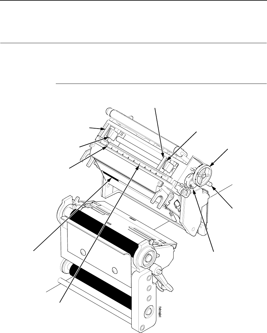
Figure 19. Adjusting the Media Sensors
The SLPA is equipped with upper and lower media sensors that detect the
top-of-form position on media with label length indicators (black marks, gaps,
notches, or holes). These media sensors also detect Paper Out conditions.
Use the handles on the lower media sensor to horizontally position it so that
the left edge of the sensor’s visible red LED is aligned under the left edge of
the adhesive label of the installed media.
Adhesive Label
(left edge)
Lower Media Sensor
(left edge)
Lower Media
Sensor Handle (2)
Positioning The Media Sensors
51
The upper media sensor, located in the slot under the printhead cover
(see Figure 18 on page 49), should be located directly over the lower media
sensor.
The lower media sensor should not be placed in the path of media features
that could cause false gap detection or paper out faults. Such features are
dark pre-printing, rounded die cut label corners, and extraneous cut-outs.
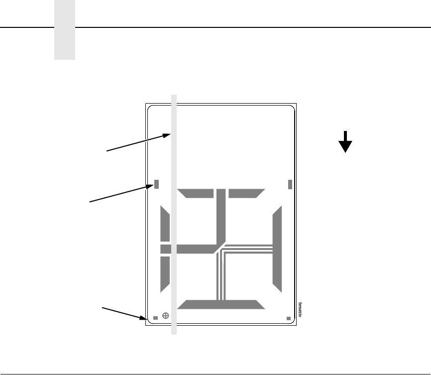
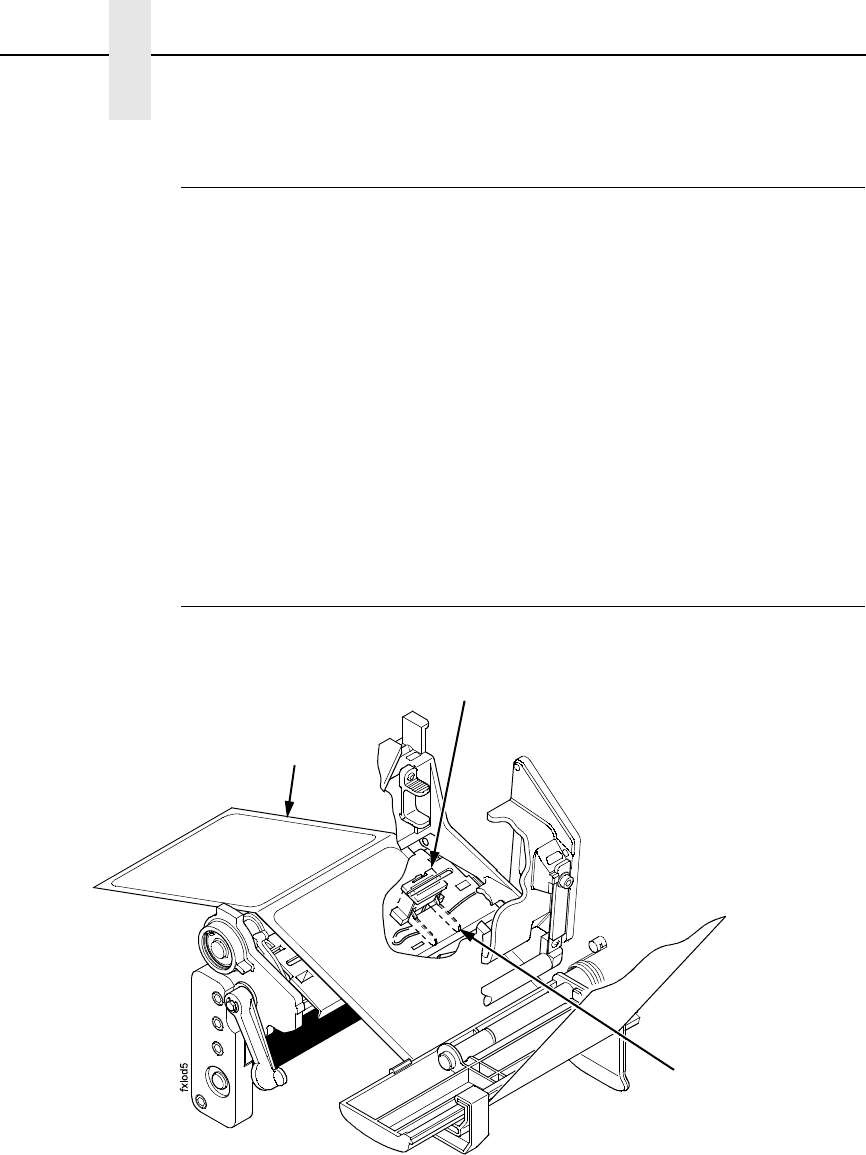
Figure 20. Positioning the Lower Media Sensor in Relation to the Label
Avoid Rounded
Die Cut Label
Corner
Position the lower
media sensor in the
grey shaded area.
Avoid Pre-Printing
FEED

52
Chapter 4 System Adjustments
Sensing Different Media Types
The SLPA’s media sensors can detect the different types of label length
indicators on a large variety of media types. This requires changes to the
Gap/Mark Sensor menu item in the CALIBRATE CTRL menu:
1. Press the Menu key to take the SLPA offline and into Menu mode.
2. Press ↓ and ↵ together until ENTER SWITCH UNLOCKED displays.
3. Press the Menu key until CALIBRATE CTRL displays.
4. Press ↓ until Gap/Mark Sensor / Disable* (the currently enabled option)
displays.
5. Press + or – until the option that matches the type of label length
indicators on the installed media displays:
•Disable. The default. Select when using media with no label length
indicators (no black marks, gaps, notches, or holes) or
when you
want the SLPA to ignore all existing label length indicators on the
installed media. See instructions below.
NOTE: When you select Disable, the length of each label is based on the
Label Length value entered in the QUICK SETUP menu or the value
sent via host software.
•Mark. Select when using media that has horizontal black marks
located on the underside of the label liner or tag stock. See page 53.
•Gap.
Select
when using media with a liner space between die cut
labels or when using tag stock with notches or holes as label length
indicators on white background media. See page 54.
•Advanced Gap. Select when using media that has liner gaps
between die cut labels with a black background. See page 55.
•Advanced Notch. Select when using media with notches or holes
that interrupt a black vertical line on the underside of the media.
See page 56.
NOTE: If the SLPA detects a false paper out message when you change
from Advanced Gap or Advanced Notch to Gap or Mark sensing or
vice versa, press the Pause key and run Auto Calibrate (page 57).
6. Press ↵ to enable the displayed option. An asterisk (*) appears next to
the selection.
7. Press Pause until OFFLINE displays.
8. Review “Calibrating The Media Sensors” on page 57.
9. Perform the Auto Calibrate procedure on page 57.
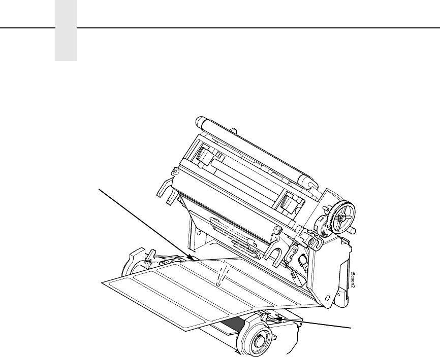
Sensing Media with No Label Length Indicators (Disable)
1. When using media without label length indicators (no marks, gaps,
notches, or holes) or when you want to ignore all existing length
indicators, place the lower sensor in the center of the media so that it can
detect a paper out condition. Place the upper sensor above it.
2. Set Gap/Mark Sensor to Disable in CALIBRATE CTRL menu. See
“Sensing Different Media Types” on page 52.
3. Perform the Auto Calibrate procedure on page 57.
Sensing Different Media Types
53
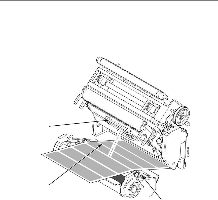
Sensing Media with Horizontal Black Marks (Mark)
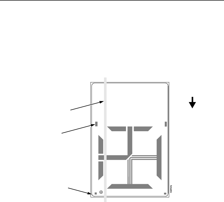
Figure 21. Media with Horizontal Black Marks
Position the lower media sensor for detecting horizontal black marks located
on the underside of media.
1. Check the position of the sensor by looking through the long, narrow
opening in the media guard. Use the visible red light emitting from the
lower sensor as a reference pointer.
2. Use the sensor handle to manually position the sensor as close as
possible to the center of the black mark on the media.
3. Set Gap/Mark Sensor to Mark in the CALIBRATE CTRL menu. See
“Sensing Different Media Types” on page 52.
4. Perform the Auto Calibrate procedure on page 57.
Lower Sensor
Media Guard
Opening
Black Mark
(underside
of media)
Sensor Handle
Visible Red Beam
from Lower Sensor
54
Chapter 4 System Adjustments
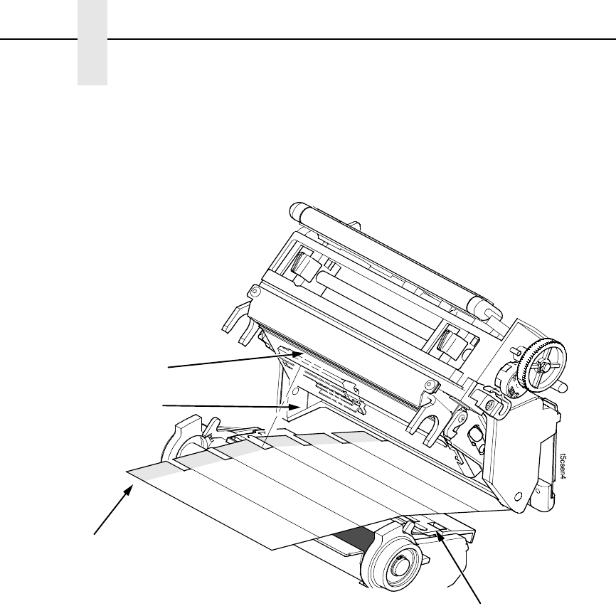
Sensing Media with Gaps, Notches, or Holes (Gap)
Figure 22. Media with Gaps, Notches, or Holes
Position the lower media sensor for detecting gaps, notches, or holes in
media with a white background. Place the upper sensor above the lower
sensor to provide a consistent background.
1. Position the lower sensor directly under the center of the gap, notch, or
hole.
2. Check the position of the lower sensor by looking through the long,
narrow opening in the media guard. Use the visible red light emitting from
the lower sensor as a reference pointer.
3. Use the sensor handle to manually position the sensor to the center of the
gap, notch, or hole in the media.
4. Set Gap/Mark Sensor to Gap in the CALIBRATE CTRL menu. See
“Sensing Different Media Types” on page 52.
5. Perform the Auto Calibrate procedure on page 57.
Media Guard
Opening
Visible Red Beam
from Lower Sensor
Sensing Different Media Types
55
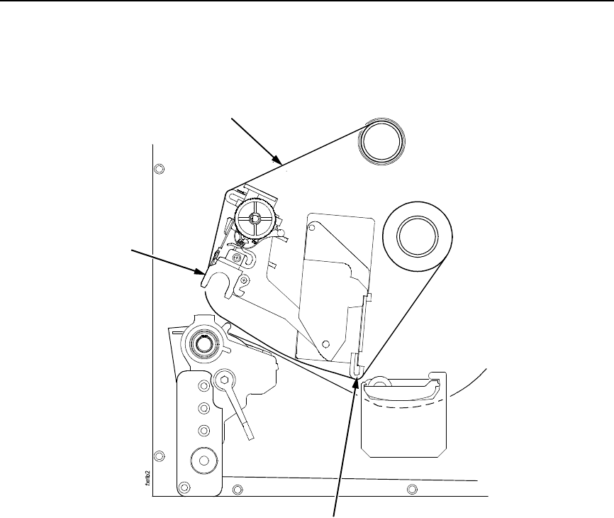
Sensing Media with Dark Background Labels with Gaps
(Advanced Gap)
Figure 23. Dark Background Media with Gaps
NOTE: Ribbon is not displayed in this illustration. The upper and lower
sensors are designed to function with or without ribbon installed.
The upper sensor and lower sensor are used together to detect liner gaps
between die cut labels that have a black or dark background on white or clear
liner.
1. Position the lower sensor so that the left edge of the beam is slightly to
the right of the left edge of the die cut label directly under the center of the
gap.
2. Check the position of the lower sensor by looking through the long,
narrow opening in the media guard. Use the visible red light emitting from
the lower sensor as a reference pointer.
3. Set Gap/Mark Sensor to Advanced Gap in the CALIBRATE CTRL menu.
See “Sensing Different Media Types” on page 52.
4. Perform the Auto Calibrate procedure on page 57.
Media Guard
Opening
Visible Red Beam
Lower Sensor
Fixed Upper Sensor
56
Chapter 4 System Adjustments
Sensing Dark Background Media with Notches or Holes
(Advanced Notch)
Figure 24. Dark Background Media with Notches or Holes
NOTE: Ribbon is not displayed in this illustration. The upper and lower
sensors are designed to function with or without ribbon installed.
The upper sensor and lower sensor are used together to detect notches or
holes in media with a black or dark underside. This combination can be found
on tag stock that has a black vertical line along one edge on the underside of
the label, interrupted by a notch or hole used as the label length indicator.
1. Position the lower sensor so that the left edge of the beam is slightly to
the right of the left edge of the die cut label directly under the center of the
notch or hole.
2. Check the position of the lower sensor by looking through the long,
narrow opening in the media guard. Use the visible red light emitting from
the lower sensor as a reference pointer.
3. Set Gap/Mark Sensor to Advanced Notch in the CALIBRATE CTRL
menu. See “Sensing Different Media Types” on page 52.
4. Perform the Auto Calibrate procedure on page 57.
Visible Red Beam
Lower Sensor
Media Guard
Opening
Fixed Upper Sensor
Black line
on underside
of media

Calibrating The Media Sensors
57
Calibrating The Media Sensors
Due to manufacturing differences in media and ribbon, the media sensors
may have difficulty differentiating between the label and the liner or the label
and the black mark. When this occurs, the SLPA may intermittently skip a
label or display a fault message such as GAP NOT DETECTED / See Manual
or PAPER OUT / Load Paper.
Media sensor sensitivity and reliability can be improved by changing the
Gap/Mark Threshold and/or Paper Out Threshold values. You can change
these values automatically by performing the Auto Calibrate or Manual
Calibrate procedure in the CALIBRATE CTRL menu or change them manually
by entering your own Gap/Mark Threshold or Paper Out Threshold values.
(The changes take effect immediately within the current configuration menu.)
Auto or Manual Calibrate is completed successfully when the displayed
Sensed Distance value correctly matches that of the installed media. When
Gap is selected, the Sensed Distance value should match the length from the
trailing edge of one gap to the trailing edge of the next gap (or one label + one
gap). When Mark is selected, the Sensed Distance value should match the
length from the leading edge of one black mark to the leading edge of the next
black mark.
When you have completed Auto or Manual Calibrate, you can verify that the
new values are correct by pressing the Feed key several times. Each time you
press Feed, media advances one label and stops at the correct Top-of-Form
position of the next label.
Once you confirm the correct values, save them to the desired configuration
menu before powering off the SLPA. See “Saving A Configuration” on
page 67.
Running Auto Calibrate
You can initialize Auto Calibrate via the Apply key (described in detail below)
or via the CALIBRATE CTRL or DIAGNOSTIC menus in Menu mode.
NOTE: Verify that the Gap/Mark Sensor option (Disable, Mark, Gap,
Advanced Gap, or Advanced Notch) matches the installed media.
See “Sensing Different Media Types” on page 52.
Check that the media sensors are horizontally positioned to permit
sensing of the label length indicators. See “Positioning The Media
Sensors” on page 50.
If you try to do an Auto Calibrate when Peel-Off Media Handling is
enabled, the LCD will display CANNOT CALIBRATE / Disable Peel-
Off. Before you can do an Auto Calibrate, you must select another
media handling mode.
1. Press the Pause key until OFFLINE displays on the LCD.
2. Press ↓ and ↵ together until ENTER SWITCH UNLOCKED displays.
3. Press the Apply key until Printer Tests / Auto Calibrate displays.
4. Press ↵. Media advances until it can accurately detect the label length
indicators and then stops at the Top-of-Form position. The Sensed
Distance value will then display for one second.

58
Chapter 4 System Adjustments
5. Auto Calibrate is successful when the Sensed Distance value correctly
matches that of the installed media:
•Gap/Mark Sensor = Gap, Advanced Gap, or Advanced Notch:
The Sensed Distance value is the physical length of one label plus
the length of one gap, notch, or hole.
•Gap/Mark Sensor = Mark: The Sensed Distance value is the
physical distance from the leading edge of one black mark to the
leading edge of the next.
•Gap/Mark Sensor = Disable: Not applicable. If Gap/Mark Sensor is
set to Disable, the Sensed Distance value will not be updated.
If GAP NOT DETECTED displays, run Auto Calibrate again.
If Auto Calibrate continues to end with an incorrect Sensed Distance
value displayed or a fault message displayed, run Manual Calibrate as
described on page 58.
NOTE: The amount of media sampled during Auto Calibrate is based on the
length of a label and transitions detected, without error, between a
label and its label length indicators.
6. Press the Pause key until OFFLINE displays.
7. Press the Feed key several times. Each time you press Feed, the media
advances one label length and stops.
NOTE: After a form feed, the position of the leading edge of the next label
depends on the type of Media Handling mode selected under the
QUICK SETUP menu. Tear-Off and Tear-Off Strip Media Handling
will position the label edge at the peel bar, while Continuous will
position the label edge under the printhead.
8. Press the Pause key until ONLINE displays.
9. Once the Sensed Distance value is confirmed, save it to the desired
configuration (page 67) before powering off the SLPA.
Running Manual Calibrate
Manual Calibrate should be performed only when the values derived from
Auto Calibrate fail to improve the media sensors’ ability to sense label length
indicators on the installed media. You must first enable Admin User in the
PRINTER CONTROL menu before accessing or initializing Manual Calibrate
in the CALIBRATE CTRL menu.
NOTE: Verify the Gap/Mark Sensor option (Gap, Mark, Advanced Gap,
Advanced Notch, or Disable) matches the installed media. See
“Sensing Different Media Types” on page 52.
Ensure the media sensors are horizontally positioned to permit
sensing of the label length indicators. See “Positioning The Media
Sensors” on page 50.
Ensure the Print Mode option selected in the QUICK SETUP menu
matches the media installed. Select Direct for heat sensitive media
(no ribbon required) or Transfer for thermal transfer media (ribbon
required).

Calibrating The Media Sensors
59
If you try to do a Manual Calibrate when Peel-Off Media Handling is
enabled, the LCD will display, CANNOT CALIBRATE / Disable Peel-
Off. Before you can do a Manual Calibrate, you must select another
media handling mode.
1. Press the Menu key to take the SLPA offline and into Menu mode.
2. Press the ↓ and ↵ keys together until ENTER SWITCH UNLOCKED
displays.
3. Press the Menu key until PRINTER CONTROL displays.
4. Press ↑ until Admin User displays.
5. Press + until Enable displays.
6. Press ↵ to select Enable. An asterisk (*) appears next to Enable.
7. Press the Menu key until CALIBRATE CTRL displays.
8. Press ↓ until Manual Calibrate / Run Calibrate displays, then press ↵.
9. Follow the instructions displayed on the LCD. Example: REMOVE
RBN&MEDIA / Press Enter indicates that you must open the pivoting
deck and remove the ribbon and media from under the printhead, close
and lock the pivoting deck, and press the ↵ key.
During the last step of Manual Calibrate, the SLPA will advance the media
and attempt to detect the label length indicators and stop at the Top-of-
Form position. The Sensed Distance value will then display for one
second. The calibrate is successful when the Sensed Distance value
correctly matches that of the installed media.
If CALIBRATION FAIL / See Manual displays, run Manual Calibrate
again.
NOTE: The amount of media sampled during Manual Calibrate is based on
the length of a label and the transitions detected without error,
between a label and its label length indicators.
10. Press the Pause key until OFFLINE displays.
11. Press the Feed key several times. Each time you press Feed, the media
advances one label length and stops.
NOTE: After a form feed, the position of the leading edge of the next label
depends on the type of Media Handling mode selected under the
QUICK SETUP menu. Tear-Off and Tear-Off Strip Media Handling
positions the label edge at the peel bar, while Continuous positions
the label edge under the printhead.
12. Once the correct values are confirmed, save them to the desired
configuration (page 37) before powering off the SLPA.

60
Chapter 4 System Adjustments

61
5Illustrated Parts
Breakdown
Organization Of This Chapter
This chapter contains drawings of the electromechanical assemblies
comprising the SLPA. The table following each illustration lists the illustrated
parts and their part numbers.
Items marked “Ref” (reference) are not spared, are part of another assembly,
or are shown elsewhere.
Illustrated Parts Breakdown
Figure 25. Ribbon Drive Assembly .......................................................................................page 62
Figure 26. Pneumatic Assembly........................................................................................... page 64
Figure 27. Brake Assembly .................................................................................................. page 66
Figure 28. 14 inch Cylinder Assembly ..................................................................................page 68
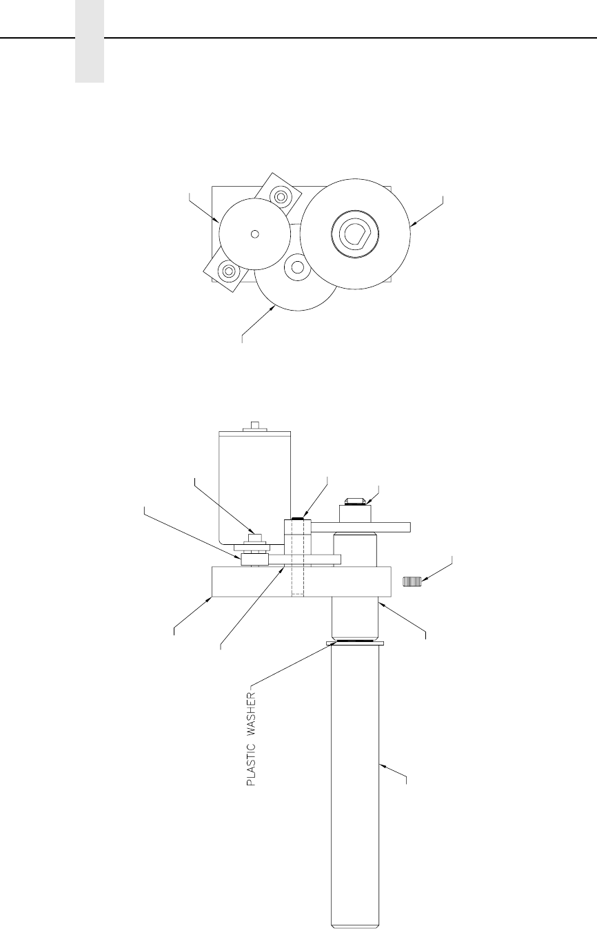
62
Chapter 5 Illustrated Parts Breakdown
Figure 25. Ribbon Drive Assembly
1, 14
2
3
5
7
8
6
9
10
11
12
4, 13

63
Item
No. Part No. Description Notes
1 Ref Ribbon Spindle Tube
2 Ref Ribbon Motor Spacer
3 Ref Ribbon Gear Drive Block
4 Ref External RR 0.250 inch Shaft (E Ring)
5 Ref Ring Ret Ext Ser 5304 0.375 D
(E-Style)
6 Ref SHSS #10-32x0.375 Lg
7 Ref Flat Washer 1/4 inch
8 Ref SHCS M4 x 0.70 x 20 mm
9 172264-001 Field Kit, Ribbon Spindle, 4 inch
10 750569-001 Gear, Ribbon Drive, Final
11 750568-001 Gear, Ribbon Drive, Intermediate
12 171403-001 Field Kit, DC Motor
13 Ref Shaft, Intermediate, 0.250 Dia.
14 Ref Shaft Bearing, 0.437 ID
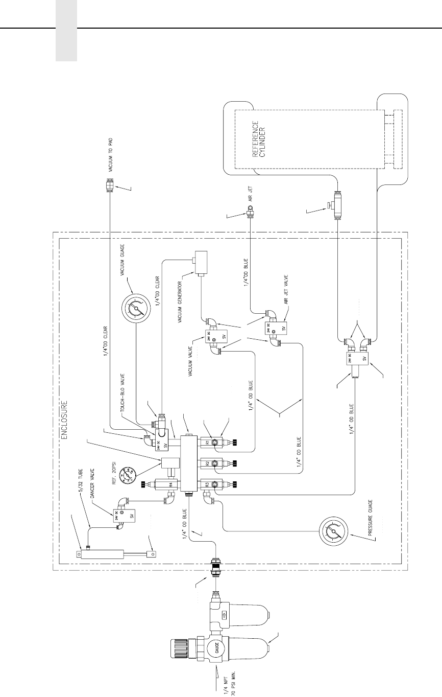
64
Chapter 5 Illustrated Parts Breakdown
Figure 26. Pneumatic Assembly
1, 5
2
1, 6
3
4
7
7
8
9
10
11
12
13
14
15
16
17
18
19
20
21
22
23
8
8
13
13
13

65
Item
No. Part No. Description Notes
1 Ref Gauge Clamp
2 Ref Manifold, 1.250 inch Reg. Spacing
3 Ref 1/8 NPT Pipe Plug, Socket H
4 Ref Close Nipple 1/8 NPT
5 178631-001 Pressure Gauge, 100 psi
6 178632-001 Vacuum Gauge, 30 hg
7 Ref 1/4 x 0.159 Tubing-Blue Polyurethane
8 Ref 1/4 Tube 1/8 NPT Elbow
9 Ref #10 Male Elbow Fitting
10 Ref #10 Male Fitting
11 Ref Air Cyl. Piston Rod Clevis
12 Ref Double Acting Air Cyl. 9/16 x 4
13 178520-001 Valve, Air Cyl., 3 Way with Diode
14 178521-001 Valve, Air Cyl., 4 Way with Diode
15 Ref Regulator (3)
16 Ref Flow Control, Inline
17 178633-001 Filter/Mist/Reg. Combo
18 Ref Bulkhead Union, 1/4 OD Tube to
1/4 OD Tube
19 Ref Check Valve
20 Ref Branch Tee, 1/4 Tube 1/8 NPT
21 Ref Adapter 1/8 NPT F to #10-32 M
22 Ref 1/4 Tube to #10-32 M Elbow (4)
23 178522-001 Vacuum Generator
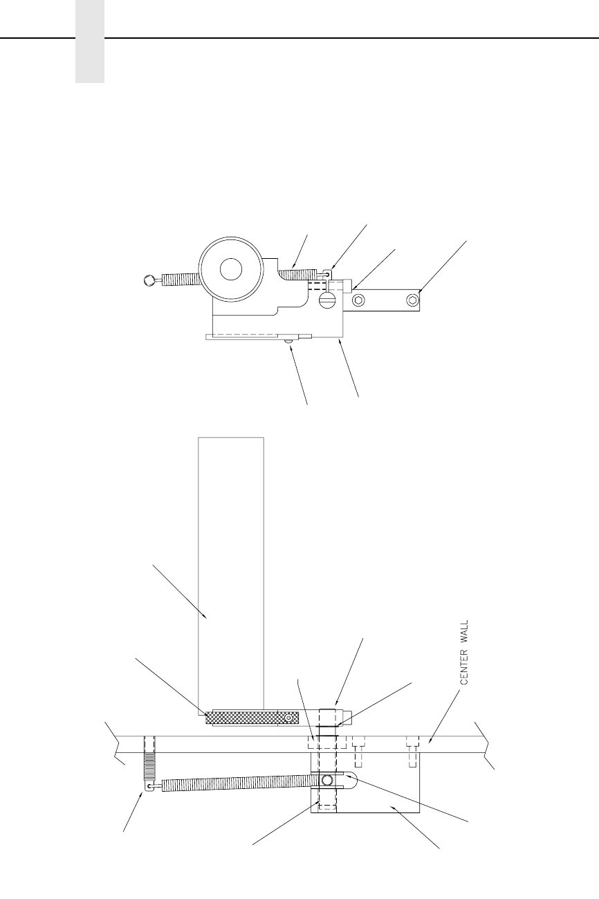
66
Chapter 5 Illustrated Parts Breakdown
Figure 27. Brake Assembly
1, 8
2
4
3
5
6
7
9
10
11
12
13
14
15
16

67
Item
No. Part No. Description Notes
1 Ref Media Roller Sub-Assembly
2 178518-001 Brake Pad
3 Ref Brake Shaft
4 Ref Spring Post
5 Ref Block
6 Ref 4601 Brake Arm
7 Ref Ring Ret. Ext. Ser. 5100 0.375 D
8 Ref FHSCS #10-32x0.500 Lg
9 Ref BHCS #6-32x0.375 Lg
10 Ref SHCS #8-32x0.500 Lg
11 Ref SHCS #8-32x0.625 Lg
12 Ref Extension Spring 3.25 Lg
13 Ref Ball Bearing 0.375 ID x 0.875 OD
14 Ref Sleeve Bearing 3/8 inch ID x
7/16 inch OD x 3/8 inch Long
15 Ref Thrust Bearing, Bronze 3/8 ID 3/4 OD
x 0.06 Thk.
16 Ref Spring Anchor 8-32 Thds.
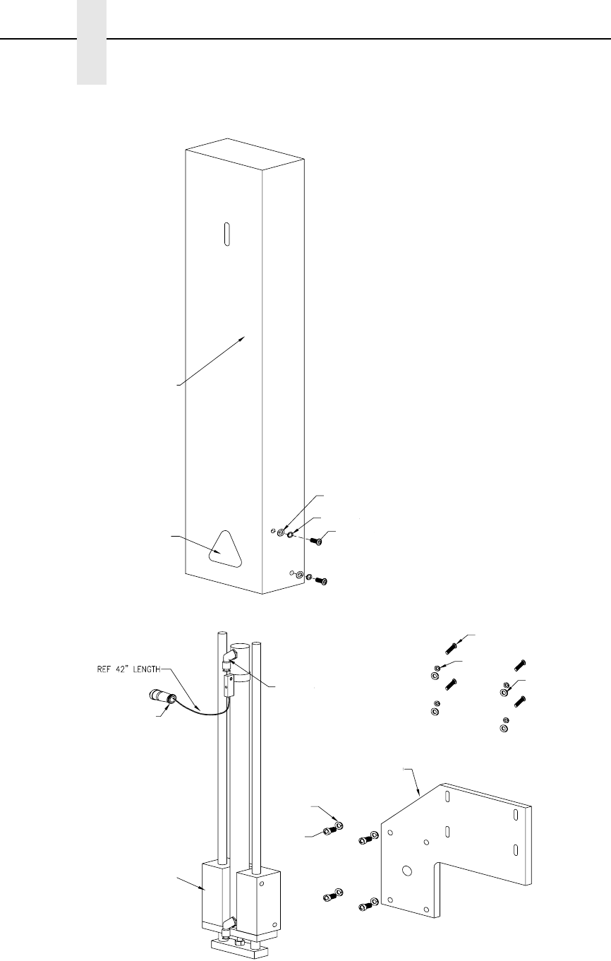
68
Chapter 5 Illustrated Parts Breakdown
Figure 28. 14 inch Cylinder Assembly
1
2
3
4
5
6
7
8
9
10
11
12 13
14

69
Item
No. Part No. Description Notes
178499-901 Cylinder Assy, Swing, 14 inch/356 mm Includes all items shown in
Figure 28.
1 Ref Cylinder Cover, 14 inch
2 Ref Solid State Swith Assy, 14 inch
3 Ref Cylinder Bracker, 20 mm
4 Ref SHCS 1/4-20x0.750 Lg
5 Ref Washer Splitlock 0.250
6 Ref BHCS M5x0.08x10mm Lg
7 Ref BHCS M6x1.00x12mm Lg SS
8RefFW M5 SS
9RefLW M5 SS
10 Ref Fastener M6 Lock Washer SS
11 Ref Pinch Point Warning Label
12 Ref 1/4 Tube 1/8 NPT Elbow
13 Ref Washer 1/4 inch (grade 8 steel)
14 178519-001 Slide Assembly 350 mm Stroke

70
Chapter 5 Illustrated Parts Breakdown

71
A
Adjustments
cylinder extend time, 41
label application, 39
media sensor, 50
pressure block, left, 50
pressure block, right, 50
printhead pressure, 49
Adjustments, system, 49
Advanced gap, media sensing, 52, 55
Advanced notch, media sensing, 52, 56
Air cylinder regulator control valve, 28
Air jet adjustment control valve, 28
AIR JET control valve, 28
Air jets, position, 19
Applicator delay menu mode, 29
Applicator pad, cleaning, 46
Apply label, 42
Auto Calibrate
running, 21
Auto calibrate
running, 57
C
Calibrating media sensors, 57
Cleaning, 43
applicator pad, 46
media sensor, 45
platen roller, 45
printhead, 45
schedule, 48
vacuum generator, 47
Configuration, saving, 37
Control gauges, pneumatic, 28
Control panel status, keypad, 24
Control valves, pneumatic, 28
CYLINDER control valve, 28
Cylinder extend time adjustments, 41
D
Dark background labels with gaps, 55
Dark background media with notches or holes, 56
Data indicator light, 27
F
Functions, keypad, 24
G
Gap, media sensing, 52, 54
Gap/Mark Sensor option, 35
General cleaning, 43
H
Holes, media sensing, 54
Hor Image Shift option, 33
Horizontal black marks, 53
I
Indicator descriptions, 26
Indicator light
data, 27
Online status, 26
Indicators, keypad, 24
J
Jets, air, 19
Index

72
K
Key descriptions, 26
Keypad
control panel status, 24
functions, 24
indicators, 24
L
Label application
adjustments, 39
process, 42
Label backing, remove, 7
Label Length option, 33
Label print process, 42
Label roll, threading, 8
Label Width option, 33
LCD, 24
Left pressure block adjustment, 50
Liquid Crystal Display, 24
Load ribbon, 16
M
Manual calibrate, running, 58
Mark, media sensing, 52, 53
Media Handling option, 32
Media sensing
dark background media with notches or
holes, 56
sensing different types of media, 52
with dark background labels with gaps, 55
with gaps, notches, or holes, 54
with horizontal black marks, 53
Media sensor
disable, 52
gap, 52
mark, 52
Media sensor adjustment, 50
Media sensors
calibrating, 57
cleaning, 45
Menu
Applicator delay, 29
mode, 27
Mode
Applicator delay menu, 29
menu, 27
offline, 26
online, 26
N
Notches, media sensing, 54
Numbers, part, replaceable parts, 61
O
Offline mode, 26
Online mode, 26
Online status indicator light, 26
Onsite maintenance service, 4
Orientation option, 33
P
Paper Feed Shift option, 32
Part numbers, replaceable parts, 61
Platen roller, cleaning, 45
Pneumatic control valves
air cylinder regulator, 28
air jet adjustment, 28
vacuum adjustment, 28
Pneumatic control valves and gauges, 28
Position air jets, 19
Positioning the media sensors, 50
Power-Up Config. option, 36
Print Intensity menu item, 31
Print Mode menu item, 32
Print Speed menu item, 31
Printhead pressure adjustment, 49
Printhead pressure block adjustments, 50
Printhead, cleaning, 45
Process, print label, 42
Q
QUICK SETUP
menu, 30
menu items, 31

73
R
Remove label backing, 7
Replacement parts, 61
Replacing
vacuum generator, 47
Ribbon
loading, 16
Right pressure block adjustment, 50
Roll, label threading, 8
Running
auto calibrate, 57
manual calibrate, 58
Running auto calibrate, 21
S
Save Config. option, 36
Saving the configuration, 37
Schedule, cleaning, 48
Sensing different media types, 52
Spare parts and part numbers, 61
Supplies information, 4
System adjustments, 49
T
Thread label roll, 8
V
Vacuum adjustment control valve, 28
VACUUM control valve, 28
Vacuum generator
cleaning, 47
replacing, 47
Ver Image Shift option, 33
W
Warranty, 4

74
179414-001A
*179414-001*
For technical assistance, contact your
Distributor/VAR/Reseller for service.
For further assistance, contact the Printronix Customer Support Center.
Printronix Customer Support Center
Americas (714) 368-2686
Web site: http://www.printronix.com/public/servicessupport/default.aspx
Printronix Supplier Center
Americas (800) 733-1900
Web site: http://www.printronix.com/public/supplies/default.aspx
Printronix, Inc.
14600 Myford Road
P.O. Box 19559
Irvine, CA 92623-9559
Phone: (714) 368-2300
Fax: (714) 368-2600
Or visit the Printronix web site at www.printronix.com