Printronix ADMP2PA Print and Apply Machine User Manual PTX UM SLPA7000r 250117A
Printronix Inc Print and Apply Machine PTX UM SLPA7000r 250117A
Contents
- 1. Users Manual 1
- 2. Users Manual 2
- 3. Users Manual 3
Users Manual 2
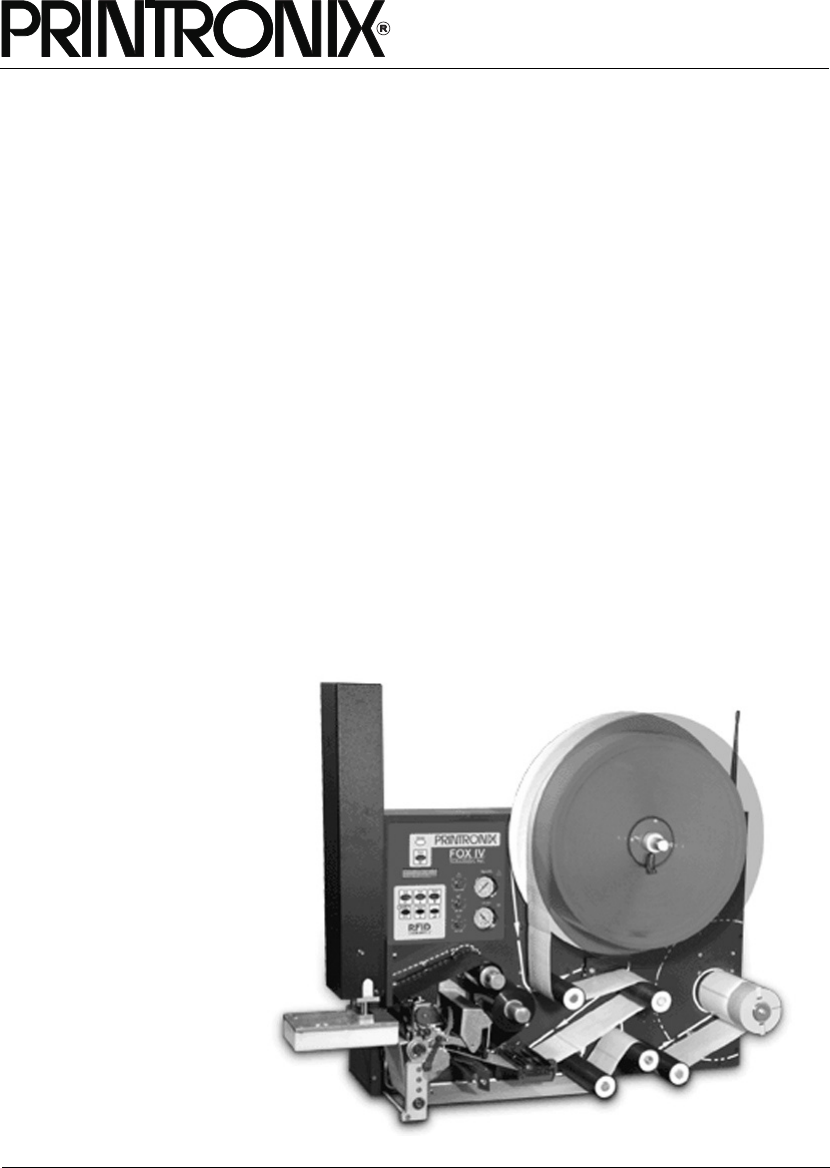
SLPA7000r Smart Label Printer Applicator
User’s Manual

User’s Manual
SLPA7000r Smart Label Printer Applicator

IMPORTANT WARRANTY INFORMATION
PRINTER WARRANTY
Printronix® warrants to the purchaser that under normal use and service, this printer (excluding
the thermal printhead) purchased hereunder shall be free from defects in material and
workmanship for a period of one year from the date of shipment from Printronix. (In the United
States and Canada, this period provides for onsite support service in the first 90 days of
ownership, with return-to-factory service provided from the 91st day of ownership until the end of
one year, costs of shipping to be borne by the purchaser.)
Consumable items such as media and ribbons are not covered under this warranty. This warranty
does not cover equipment or parts that have been misused, altered, or used for purposes other
than those for which they were manufactured. This warranty also does not cover loss, shipping
damage, damage resulting from accident or damages resulting from unauthorized service.
THERMAL PRINTHEAD
Printronix warrants the printhead for a period of one hundred eighty (180) days, or 1,000,000 linear
inches for direct thermal use, or 2,000,000 linear inches for thermal transfer use, whichever comes
first. The warranty does not cover printheads that have been misused, damaged due to improper
cleaning, or damaged due to use of improper ribbons or media.
SUPPLIES
For the nearest Printronix full-service distributor that carries Printronix genuine supplies, please
call 1-800-733-1900 or fax (714)-368-2354. Supplies design, specification, and selection are
integral to the development of any computer imaging system. Printronix's extensive manufacturing
and research capabilities, along with years of experience in the design of printers and their
applications, assures that you will receive the exact materials that you require to maximize the
performance of your Printronix printer. For more information, call the Printronix Customer
Solutions Center at (714) 368-2686 or access the Printronix website at http://www.printronix.com.
ON-SITE MAINTENANCE SERVICE
Printronix offers on-site support services in the United States and Canada. Please contact the
Printronix Maintenance Contracts Group at 800-854-6463 - option 1 for detailed service
agreement information.
Model ____________ Setup Values
Software Version ___________________________
Touch-Blo Control ___________________________
Print Mode ___________________________
Apply Mode ___________________________
Print Darkness ___________________________
Machine Type ___________________________
Pinch Roller ___________________________
Random Stroke Delay ___________________________
Cycle Time Delay ___________________________
Cylinder Extend Time ___________________________
Vacuum Delay Time ___________________________
CPU Dip Switch Settings __________________________
Printer Serial Number ___________________________

Communication Notices
This equipment has been tested and found to comply with the limits for a Class B digital device,
pursuant to Part 15 of the FCC Rules. These limits are designed to provide reasonable protection
against harmful interference in a residential installation. This equipment generates, uses, and can
radiate radio frequency energy and, if not installed and used in accordance with the instructions,
may cause harmful interference to radio communications. However, there is no guarantee that
interference will not occur in a particular installation. If this equipment does cause harmful
interference to radio or television reception, which can be determined by turning the equipment off
and on, the user is encouraged to try to correct the interference by one or more of the following
measures:
•Reorient or relocate the receiving antenna.
•Increase the separation between the equipment and receiver.
•Connect the equipment into an outlet on a circuit different from that to which the receiver is
connected.
•Consult the dealer or an experienced radio/TV technician for help.
Unauthorized changes or modifications could void the user’s authority to operate the equipment.
This device complies with part 15 of the FCC Rules. Operation is subject to the following two
conditions: (1) this device may not cause harmful interference, and (2) this device must accept any
interference received, including interference that may cause undesired operation.
Any change or modification to this product voids the user’s authority to operate it per FCC Part 15
Subpart A Section 15.21 regulations.
This product contains an intentional radiator with the following parameters:
Operating Frequency: 902 to 928 MHz
Typical RF Power: 25 to 100 milliwatts (SL5x04 MP) or 25 to 205 milliwatts (SL5x04 C1)
Maximum RF Power: 1 Watt under abnormal conditions
Canada
This Class B digital apparatus complies with Canadian ICES-003 and
RSS 210.
Cet appareil numérique de la classe B est conforme à la norme NMB-003
du Canada.
Operation is subject to the following two conditions: (1) this device may not cause interference,
and (2) this device must accept any interference, including interference that may cause undesired
operation of the device.
This device has been designed to operate with the antennas listed below, and having a maximum
gain of –18 dBi. Antennas not included in this list or having a gain greater than –18 dBi dB are
strictly prohibited for use with this device. The required antenna impedance is 50 ohms.
Tested To Comply
With FCC Standards
Printronix SL5000r and T5000r
FOR HOME OR OFFICE USE
To reduce potential radio interference to other users, the antenna type and its gain should be so
chosen that the equivalent isotropically radiated power (e.i.r.p.) is not more than that permitted for
successful communication.
CE Notice (European Union)
Marking by the CE symbol indicates compliance of this Printronix system to the EMC Directive and
the Low Voltage Directive of the European Union. Such marking is indicative that this Printronix
system meets the following technical standards:
•EN 300 220-1 (2000), Electromagnetic Compatibility and Radio Spectrum Matters; Short
Range Devices; Radio equipment to be used in the 25 MHz to 1000 MHz frequency range with
power levels ranging up to 500 mW.
•EN 55022 — “Limits and Methods of Measurement of Radio Interference Characteristics of
Information Technology Equipment.”
•EN 50082-1: 1992 — “Electromagnetic compatibility—Generic immunity standard Part 1:
Residential, commercial, and light industry.”
•EN 60950 — “Safety of Information Technology Equipment.”
This printer is a Class B product for use in a typical Class B domestic environment.
CE Symbol
Taiwan

Trademark Acknowledgements
Compatibility Software Copyright © 1989 Phoenix Technologies Ltd., All Rights Reserved.
Alien and Alien Technology are registered trademarks of Alien Technology Corporation.
Code V is a trademark of Quality Micro Systems, Inc.
EIA is a registered service mark of the Electronic Industries Association.
Epson is a registered trademark of Seiko Epson Corporation.
HP is a registered trademark of Hewlett-Packard Company.
IBM is a registered trademark of International Business Machines Corporation.
IGP, LinePrinter Plus, PGL, Printronix, and PSA are registered trademarks of Printronix, Inc.
IPDS is a trademark of International Business Machines Corporation.
LaserJet is a registered trademark of Hewlett-Packard Company.
Microsoft, MS-DOS, and Windows are registered trademarks of Microsoft Corporation.
PCL is a registered trademark of Hewlett-Packard Company.
PhoenixPage PCL 5 is a registered trademark of Phoenix Technologies Ltd.
PostScript is a registered trademark of Adobe Systems.
PPI1, PPI2, SLPA7000e are trademarks of Printronix, Inc.
Proprinter is a registered trademark of International Business Machines Corporation.
QMS is a registered trademark of Quality Micro Systems, Inc.
TEC is a registered trademark of the Toshiba TEC Corporation.
Zebra is a registered trademark of Zebra Technologies Corporation.
Copyright 2004, 2005, Printronix, Inc.

9
1 Introduction ......................................................... 15
Printronix Customer Support Center.................................................... 15
Printronix Supplies Department..................................................... 15
Corporate Offices .......................................................................... 16
To Replace Parts .......................................................................... 16
To Order Parts .............................................................................. 17
Notes And Notices ........................................................................ 17
Manual Conventions ..................................................................... 18
Related Manuals ........................................................................... 18
Overview.............................................................................................. 19
General Operation......................................................................... 19
Operating Specifications ............................................................... 20
Storage, Shipping, & Handling ...................................................... 21
Safety................................................................................................... 22
Warnings And Cautions ................................................................ 22
Operating Precautions .................................................................. 23
Operational Safety ........................................................................ 23
The SLPA7000r Series Label Printer................................................... 24
Standard Features ........................................................................ 24
Optional Features.......................................................................... 25
Thermal Printer Media................................................................... 26
Ribbons ......................................................................................... 26
Thermal Printer Technology.......................................................... 26
Installing The SLPA ............................................................................. 28
Unpacking Your SLPA .................................................................. 28
Mounting The SLPA ...................................................................... 28
Optional Mounting Accessories..................................................... 29
Mounting The Beacon ................................................................... 29
Air, Power, And Communications Connections............................. 30
Adjusting The Voltage ................................................................... 33
Table Of Contents

10
Table of Contents
2 Operation ............................................................ 35
Control Panel....................................................................................... 35
LCD ............................................................................................... 36
Keypad .......................................................................................... 36
Key and Indicator Descriptions ..................................................... 38
Pneumatic Control Valves And Gauges........................................ 40
Setup ................................................................................................... 41
Threading The Label Roll.............................................................. 41
Loading Ribbon ............................................................................. 49
Positioning The Air Jets ................................................................ 52
Removing Label Backing .............................................................. 53
SLPA System Configuration Parameters............................................. 53
System Adjustments ............................................................................ 55
Printhead Pressure Adjustment .................................................... 55
Printhead Pressure Block Adjustments......................................... 56
Positioning The Media Sensors .................................................... 56
Sensing Different Media Types ..................................................... 58
Calibrating The Media Sensors..................................................... 63
Printing And Applying Labels............................................................... 68
Label Application (Positioning) Adjustments ................................. 68
Adjusting The Cylinder Extend Time ............................................. 70
The Print And Apply Process ........................................................ 71
3 Configuring The SLPA ........................................ 73
Setting Printer Configuration Parameters ............................................ 73
Moving Within The Configuration Menu............................................... 73
Selecting A Menu Option .............................................................. 74
Changing Printer Settings ............................................................. 74
Saving A Configuration ................................................................. 75
Auto Save Configuration ............................................................... 76
Specifying A Power-Up Configuration........................................... 77
Modifying A Saved Configuration.................................................. 78
Printing A Configuration ................................................................ 79
Main Menus ......................................................................................... 82
QUICK SETUP Menu .......................................................................... 88
QUICK SETUP Submenus............................................................ 89
RFID CONTROL Menu........................................................................ 97
RFID CONTROL Submenus ......................................................... 99
Admin User Submenus ............................................................... 102
CONFIG. CONTROL Menu ............................................................... 105
CONFIG. CONTROL Submenus ................................................ 106

Table of Contents
11
MEDIA CONTROL Menu................................................................... 108
MEDIA CONTROL Submenus .................................................... 110
CALIBRATE CTRL Menu .................................................................. 125
CALIBRATE CTRL Submenus.................................................... 126
PRINTER CONTROL Menu .............................................................. 131
PRINTER CONTROL Submenus................................................ 134
IGP/PGL SETUP ............................................................................... 144
IPG/PGL Setup Submenus ......................................................... 147
DIAGNOSTICS Menu ........................................................................ 156
DIAGNOSTICS Submenus ......................................................... 157
PARALLEL PORT.............................................................................. 160
PARALLEL PORT Submenus ..................................................... 161
SERIAL PORT ................................................................................... 164
SERIAL PORT Submenus .......................................................... 165
C/T PORT .......................................................................................... 172
C/T PORT Submenus ................................................................. 172
ETHERNET ADDRESS Menu ........................................................... 173
ETHERNET ADDRESS Submenus ............................................ 174
ETHERNET PARAMS Menu ............................................................. 175
ETHERNET PARAMS Submenus............................................... 176
WLAN ADDRESS.............................................................................. 178
WLAN ADDRESS Submenus ..................................................... 179
WLAN PARAMS ................................................................................ 181
WLAN PARAMS Submenus........................................................ 186
WLAN LEAP ...................................................................................... 189
WLAN LEAP Submenus ............................................................. 189
BATTERY CONTROL........................................................................ 190
BATTERY CONTROL Submenus ............................................... 191
GPIO CONTROL Menu ..................................................................... 193
GPIO CONTROL Submenus....................................................... 194
Applicator Delay Menu....................................................................... 195
4 Preventive Maintenance ................................... 197
Cleaning............................................................................................. 197
General Cleaning ........................................................................ 197
Cleaning The Printhead, Platen Roller And Media Sensors........ 199
Cleaning Procedure .................................................................... 199
Cleaning The Applicator Pad ...................................................... 200
Cleaning/Replacing The Vacuum Generator............................... 201
Cleaning Schedule ...................................................................... 202

12
Table of Contents
5 Troubleshooting ................................................ 203
Introduction........................................................................................ 203
What You Should Know About Print Quality ............................... 203
How To Maximize Printhead Life ................................................ 203
Troubleshooting At A Glance ...................................................... 204
Start Here .......................................................................................... 205
How To Troubleshoot ........................................................................ 206
Printer Tests ................................................................................ 207
To Print A Test Label .................................................................. 207
Troubleshooting Display Messages................................................... 208
List Of Messages ........................................................................ 209
Troubleshooting Other Symptoms ..................................................... 223
General Symptom List................................................................. 223
Communications Failures .................................................................. 243
Troubleshooting A New Installation ................................................... 246
Printer Configuration ................................................................... 246
GAP NOT DETECTED................................................................ 246
PRINT HEAD UP ........................................................................ 246
Ribbon......................................................................................... 246
Documentation ............................................................................ 246
A Specifications .................................................... 247
Applicator Orientation ........................................................................ 247
Product Distance Variation ................................................................ 247
Application Rate................................................................................. 247
Printing............................................................................................... 247
Media ................................................................................................. 248
Ribbon ............................................................................................... 249
Electrical ............................................................................................ 250
Pneumatic.......................................................................................... 250
Environmental.................................................................................... 251
Physical ............................................................................................. 251
Connections....................................................................................... 252
Communications Interface................................................................. 252

Table of Contents
13
B Options.............................................................. 253
Expansion Modules ........................................................................... 253
Beacon Package Options .................................................................. 253
Fault/Warning Beacon Package.................................................. 254
Label On Pad Sensor.................................................................. 254
Mounting The Beacon ................................................................. 255
Mounting Accessories........................................................................ 256
U-Arm And Accessories .............................................................. 256
Mounting Stand ........................................................................... 257
Low Label Sensor .............................................................................. 258
Product Sensor .................................................................................. 259
Application Options............................................................................ 261
Cylinder Stroke Lengths .............................................................. 261
Soft Pad ...................................................................................... 261
Random Stroke Sensor ............................................................... 261
C Downloading Software ...................................... 263
Loading Flash Memory ...................................................................... 263
Loading Software With The Firmware Download Utility .............. 264
Loading Through The Parallel Or Serial Port Using DOS ........... 265
Loading Software If Flash Contains Only Boot Code .................. 267
Loading Software Through The NIC............................................ 268
Downloading Optional Fonts To Flash Memory .......................... 270
Downloading TrueType Fonts ..................................................... 272
Printronix Windows Driver........................................................... 273
Create And Send Download File – Online (PGL Only)................ 273
Create And Send Download File – Download Mode ................... 274
Using PTX_SETUP ..................................................................... 274
Labeling Applications .................................................................. 274
Using Downloaded TrueType Fonts............................................ 275

14
Table of Contents

15
1Introduction
CAUTION
Thoroughly review this manual before attempting to install, set up, and
operate the SLPA.
Printronix Customer Support Center
IMPORTANT
Please have the following information available prior to calling the
Printronix Customer Support Center:
•Model number
•Serial number (located on the back of the printer)
•Installed options (i.e., interface and host type if applicable to the problem)
•Configuration printout (Press PRT CONFIG on the control panel, then
press Enter)
•Is the problem with a new install or an existing printer?
•Description of the problem (be specific)
•Good and bad samples that clearly show the problem (faxing of these
samples may be required)
Americas (714) 368-2686
Europe, Middle East, and Africa (31) 24 6489 410
Asia Pacific (65) 6548 4114
http://www.printronix.com/public/servicessupport/default.aspx
Printronix Supplies Department
Contact the Printronix Supplies Department for genuine Printronix supplies.
Americas (800) 733-1900
Europe, Middle East, and Africa (33) 1 46 25 1900
Asia Pacific (65) 6548 4116
or (65) 6548 4182
http://www.printronix.com/public/supplies/default.aspx

16
Chapter 1 Printronix Customer Support Center
Corporate Offices
Printronix, Inc.
14600 Myford Road
P.O. Box 19559
Irvine, CA 92623-9559
Phone: (714) 368-2300
Fax: (714) 368-2600
Printronix, Inc.
Nederland BV
P.O. Box 163, Nieuweweg 283
NL-6600 Ad Wijchen
The Netherlands
Phone: (31) 24 6489489
Fax: (31) 24 6489499
Printronix Schweiz GmbH
42 Changi South Street 1
Changi South Industrial Estate
Singapore 486763
Phone: (65) 6542 0110
Fax: (65) 6546 1588
Visit the Printronix web site at www.printronix.com
To Replace Parts
1. Refer to the
SLPA7000r Maintenance Manual
.
2. Find the removal procedure for the part.
3. Read the entire procedure
before
you start and make sure you
understand all notes and notices, which are defined on page 17.
4. Gather the tools you will need.
5. Do the procedure.
To Order Parts
17
To Order Parts
Go to the Illustrated Parts Breakdown (IPB) in the SLAP7000r Maintenance
Manual, which contains drawings of all printer assemblies. Next to each
illustration is a list of the parts shown and their part numbers. When locating
parts, note the following:
•If a part number is listed you can order that part or assembly. If a
component is part of a field kit, order the kit.
•Parts marked “Ref” (reference) are not spared or are part of another
assembly.
•Part numbers are not listed for common fasteners.
•In illustrations, magnified details are shown with locator arrows and
letters:
•Assemblies you can order as kits are shown in the following manner:
Notes And Notices
For your safety and to protect valuable equipment, always read and comply
with information highlighted under the following special headings:
WARNING
A warning describes conditions that can harm you as well as damage
the equipment.
CAUTION
A caution describes conditions that can damage the printer or related
equipment.
IMPORTANT
Information vital to proper operation of the printer.
NOTE: Helpful and timesaving tips about printer operation and maintenance.
A
A
This arrow points to an area . . . that is magnified here, on
the same page or a
subsequent page.
90
85
80
87
To get item 80, 85, or 87, for
example, order item 90, which
is a kit containing all these
parts.

18
Chapter 1 Printronix Customer Support Center
Manual Conventions
•Control panel keys are printed in bold, uppercase letters.
Example: Press the PAUSE key to take the printer offline.
•Control panel keys are often shown by their symbol or icon (located on
the control panel directly below the key).
Example: Press the ↵ to select it.
•Liquid Crystal Display (LCD) messages are printed in uppercase letters
inside quotation marks ( “ ” ).
Example: When “OFFLINE” appears on the LCD, you may release the
PAUSE key.
•LCD fault messages display the specific fault in uppercase letters on the
top line. A corrective action in upper and lowercase letters displays on the
bottom line.
Example: PAPER OUT
Load Paper
•Key combinations (pressing keys at the same time) are indicated by the
+ (plus) symbol.
Example: Press ↓ + ↵ to unlock the ↵ key.
Related Manuals
This manual does not explain how to install, operate, configure the printer, or
how to program application software for operation with the printer. That
information is in the following manuals, available online at www.printronix.com:
•T5000 Thermal Printer User’s Manual
•T5000 Quick Reference Manual
•T5000 Maintenance Manual
•Network Interface Card User’s Manual
•IGP®/PGL Emulation Programmer’s Reference Manual
•IGP®/VGL Emulation Programmer’s Reference Manual
•IPDS™ Programmer’s Reference Manual
•LinePrinter Plus® Emulation Programmer’s Reference Manual
•Printer Protocol Interpreter (PPI) ZGL™ Programmer’s Reference Manual
•Printer Protocol Interpreter (PPI) TGL™ Programmer’s Reference Manual
•Printer Protocol Interpreter (PPI) IGL™ Programmer’s Reference Manual
•Printer Protocol Interpreter (PPI) STGL™ Programmer’s Reference
Manual
General Operation
19
Overview
General Operation
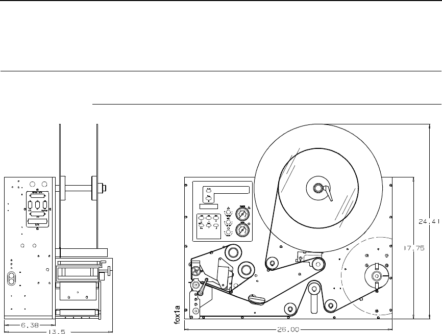
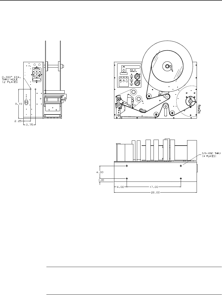
Figure 1. SLPA Dimensions
This document contains information and instructions for the Printronix Smart
Label Printer Applicator (SLPA). The SLPA can print label patterns up to 4.1
inches (104 mm) wide and applies them by means of a pneumatic applicator
system, although optional methods of applying the label are available by
design. The
User’s Manual
contains information on setup, operation, and
menu configurations, as well as adjustments and basic maintenance
procedures the operator can perform.
The SLPA is both a direct thermal and thermal transfer label printer. The
SLPA can be positioned for top, side, or bottom applications and mounted
using the mounting holes in either the base or sides.
NOTE: Specify the orientation of the SLPA when ordering. If the system is to
be used for bottom applications, custom work may be needed.
The SLPA is an integrated unit composed of the following modules:
•Label printer engine
•Label apply system
•GPIO control system
•Control panel (comprised of air controls, Liquid Crystal Display (LCD),
touch keypad/display, and air pressure gauges)
•Label supply
•Backing rewind system
These systems are packaged into a metal frame with an aluminum cover
enclosing the rest of the system. The metal frame is used for component
mounting, and all system controls are located on this frame.

20
Chapter 1 Overview
Operating Specifications
Operating Environment
The SLPA is designed for general use in warehouse and industrial
environments. It should not be exposed to liquids or damaging chemical
vapors, and will function properly in environments with an ambient
temperature between 40o to 100o F (4o to 38o C). Minimizing unnecessary
exposure to dirt and dust is also recommended.
NOTE: Optional enclosures may be purchased to protect the products in
unusually harsh environments.
Power Requirements
A properly grounded, dedicated line supplying either:
115 VAC +10%, single phase @ 50 - 60 Hz
or
230 VAC +10%, single phase @ 50 - 60 Hz.
CAUTION
It is recommended that you isolate the SLPA from its power supply by
means of a surge suppressor to minimize any potential damage to the
equipment.
A suppressor which limits voltage to 400V and has a response time of
1-5ns is highly recommended.
Air Supply
The applicator system works with a regulated 80 to 100 psi (550 to 690 kPa)
air supply that is dust and oil free. A filter is provided that is equipped with a
mist separator to remove any condensation that builds in the line.
CAUTION
The pneumatic supply line should also be dedicated to maintain the
appropriate pressure range, thereby providing relief against excess
pressure. Providing such protection should prevent the supply pressure
from exceeding 135 psi (931 kPA).

Storage, Shipping, & Handling
21
Storage, Shipping, & Handling
Storage
•Store the SLPA in a clean dry area.
•Storage temperatures should be between -40o to 150o F (-40o to 65o C).
•Do not store the SLPA with labels or printing ribbon installed.
•Store the SLPA in its original packaging if possible.
Shipping
•Observe storage conditions when shipping. Retain the shipping materials
if the SLPA is intended to be moved from site to site.
•If the original packing is not available, ensure sufficient padding/
protection for the printhead, applicator, label rollers, and rear cover.
•Carefully inspect the SLPA packaging upon receipt. If damage from
dropping, crushing, or punctures occurred, contact the carrier directly and
specify the nature of the damage.
Handling
•When handling the SLPA, do not rest or pivot it such that pressure may
be applied to the printhead assembly.
•Do not lift or pull the SLPA by gripping the applicator pad, the pneumatic
tubing, the printhead assembly, or any of the rollers which are located on
the front of the it.
NOTE: It is possible to manually position the applicator pad. Ensure that the
applicator pad is in the full up position to prevent any damage from
occurring when the SLPA is moved.

22
Chapter 1 Safety
Safety
Warnings And Cautions
WARNING
Printronix has provided the necessary guards and warnings within the
confines of the SLPA, but cannot anticipate each customer’s individual
installation and operational environments. It is the customer’s
responsibility to provide in-house safety guards to provide adequate
worker safety for their respective production settings.
WARNING
An input signal from the product sensor activates the SLPA when it is
powered on. Make certain that protective guards are properly secured
and that materials are clear of the applicator pad/printhead assembly
before powering on the SLPA.
WARNING
This manual includes instructions on basic operation and preventative
maintenance only. Only qualified technicians should perform service
procedures, i.e, procedures requiring access to the rear compartment or
power entry module of the SLPA.
WARNING
Both surge protection for the electrical supply and pressure relief for
the pneumatic supply are strongly recommended. Failure to properly
protect against extreme fluctuations in the supply sources could result
in operator injury or damage to equipment.
CAUTION
Power off the SLPA and disconnect both the power source and the air
supply prior to doing any maintenance, adjustments, and/or parts
replacement which do not require these systems to be powered on.
CAUTION
Read and become familiar with all of the instructions in this manual
before proceeding to operate the SLPA.
CAUTION
Any external communications cables to be used with the SLPA must be
properly shielded and grounded. Failure to provide proper shielding or
grounding for these cables could result in malfunctioning or damage to
the SLPA.
CAUTION
When handling the SLPA, do not rest or pivot it such that pressure may
be applied to the printhead assembly.

Operating Precautions
23
Operating Precautions
Proper operation of the SLPA depends upon timely maintenance and
appropriate operation. Always observe the following precautions:
•Use label stock which is designed for use with the SLPA. Printronix
supplied replacement stock is recommended.
•Ensure that a regulated air supply is used for the pneumatic system. Use
the appropriate filters for the removal of dirt, oil, and excessive moisture.
•Secure all protective guards, covers, and enclosures prior to operating
the SLPA. Ensure proper mounting of the SLPA prior to use.
•Do not attempt to operate an SLPA from a power source other than that
for which it was designed. Do not use any of the SLPA’s components to
power or operate any equipment except those they are intended to
operate.
•Use only Printronix replacement parts for maintenance and repair.
•You must have this manual to perform any maintenance. Use only the
appropriate tools and ensure that maintenance workers are properly
grounded if work is being performed on the circuitry.
•Do not use objects other than a finger to operate buttons on the keypad.
•Sound pressure levels indicated a maximum reading of 81 ±1dB(A).
Sound levels were determined based on printers of similar design and
assembled with a 3 x 4 inch applicator pad. Readings were taken in a low
noise environment, at approximately 1.0 meter.
NOTE: Sound levels may vary depending upon the mounting of the SLPA,
the surface to which a label is applied, and the environment in which it
is used. The size of the applicator pad can also affect sound levels, in
that larger pads can produce greater noise when applying labels.
Operational Safety
WARNING
The addition of custom safety guards in the vicinity of the label
applicator is essential to the safe operation of the SLPA. Due to the
variety of potential assembly line setups, Printronix cannot provide
sufficient guarding in a standard package. The addition of such guards
is the responsibility of the buyer.
WARNING
The SLPA should be powered off during any operation in which a
worker may be exposed to a hazardous zone. If it is necessary that the
SLPA remain powered on, make certain that the Pause button is pressed
and the product sensor is disconnected.

24
Chapter 1 The SLPA7000r Series Label Printer
The SLPA7000r Series Label Printer
The SLPA7000 Series is a family of direct thermal and thermal transfer
printers designed to print labels and tags from any MS-DOS®, Windows®, or
ASCII-based computer.
Printronix Dynamic Print Control provides exceptional print quality. A circuit
monitors the data to be printed and automatically adjusts the energy applied
to the thermal printhead for maximum performance.
The printer can communicate with the host computer via RS-232 and RS-422
serial, Centronics®-compatible parallel, IEEE® 1284 compliant parallel, and
(optionally) coax/twinax, ethernet 10/100Base-T, or wireless ethernet host
connections. The interface cable needed to connect the printer to the host
device is supplied by the user.
Standard Features
•Emulations:
•Printronix LinePrinter Plus (LP+). Provides direct compatibility with
Printronix P-series printers.
•Epson FX-1050, Proprinter IIIXL, and Serial Matrix printers.
•Printronix IGP/PGL and IGP/VGL. Provides printer system
commands for text, barcodes, graphics, lines, and boxes.
•Thermal Transfer and Direct Thermal Printing: On all printers
(except -DT models, which print only in direct thermal mode)
•Bar Codes: Support for over 20 types of bar codes
•Resident Fonts: OCRA, OCRB, Courier, Letter Gothic, and
CG Triumvirate Bold Condensed
•Download: Forms, fonts, and graphics into printer memory
•High Resolution Printhead: For sharp graphics and text
•Tear-Off Mode: For positioning the label at the peel bar
•32MB Flash memory
•8MB DRAM memory
•Auto Label Mapping®: For compatibility with programs written for
Printronix line matrix printers.
•Ventless System: For operation in environments with airborne
particulate matter without compromising performance
•ZGL, TGL, IGL, and STGL Interpreters: PPI/ZGL (ZebraTM), PPI/TGL
(TEC), PPI/IGL (Intermec), and PPI/STGL (SATO) interpreters are
powerful integration tools that allows the SL5000r/T5000r to function in
virtually all legacy ZPLTM, TEC, IPL, and SGL application environments
without requiring modification to host data stream.

Optional Features
25
•Standard interfaces:
•Serial: RS-232
•USB 2.0 Universal Serial Bus
•Parallel: Centronics®-compatible parallel, IEEE® 1284 compliant
parallel
NOTE: The interface cable needed to connect the printer to the host device is
supplied by the user.
Optional Features
The following options are also available:
•Fonts: A selection of fonts can be loaded from the host computer into
printer memory. Once loaded, these fonts are accessed in the same way
as the resident fonts. See Table 16 on page 270 for a list of optional fonts.
•Memory Expansion (for non-IPDS printers only):
•16MB DRAM SIMM (single in-line memory module): Provides
additional memory to accommodate long label formats. Replaces
standard 8 MB Flash SIMM.
•Twinax/Coax Host Interface: Provides connection to a host computer
system using a coaxial or twinaxial interface.
•Network Interface Card (NIC): This option allows you to attach the
printer to a LAN (Local Area Network) rather than attaching it directly to a
host computer.
NIC adapters are available as an internally installed option, mounted
inside the printer with the 10/100Base-T (UTP) connection only.
NOTE: In this manual, the terms “Network Interface Card” (or “NIC”) and
“Ethernet” are used interchangeably.
•Wireless NIC: This card provides wireless 802.11b connectivity without
expensive cabling and reconfigurations required from a wired network.
•IPDS: Available for coax/twinax, a NIC, or a combination of both. The
printer may be ordered with this option installed and the required
hardware to support it, or it can be field installed by an authorized service
representative at a later date. The printer must have a coax/twinax
interface or NIC, 300 dpi printhead, 16 MB DRAM, and 10 MB flash
memory installed to support this field-installed option.
•TN5250/TN3270: Enables your printer to communicate with an IBM host
through a NIC using the 5250/3270 datastream. This feature allows you
to use an application generated for the twinax/coax emulation to be
printed through the NIC.
•RS-422: Serial interface option.

26
Chapter 1 The SLPA7000r Series Label Printer
Thermal Printer Media
Because there are two modes of operation, there are two kinds of thermal
printer paper:
•Direct thermal paper: This paper is coated with chemicals that act as
accelerators, ink, and ink binders. In direct thermal mode, the heat from
the thermal printhead contacts the paper and causes a chemical reaction
on the surface of the paper.
•Thermal transfer paper: This film or synthetic paper substitute is
designed to accept transferred images well and to resist scratching. Most
thermal transfer papers can be die-cut for easy label applications.
Printronix offers a selection of thermal transfer paper sizes and face
stocks, which ensures high print quality and long life when used with
Printronix ribbons.
Ribbons
Use only Printronix Genuine Thermal Ribbons in this printer. Printronix
thermal ribbons are engineered to enhance thermal printing capabilities and
to prevent premature wear of the printhead.
Thermal Printer Technology
Unlike a dot matrix, laser, or LED printhead printer, a thermal printer has a
printhead containing heating elements that are used with paper or a ribbon
specially designed for use with a heated printhead. The SLPA uses an inline
thermal printhead, which produces high resolution output quickly and
efficiently.
The Printing Process
The thermal printhead allows two modes of operation:
•Direct Thermal Mode: The thermal printhead selectively heats tiny
rectangular
dots on its surface.
When the heated dots contact specially
coated thermal paper, the dyes and developers in the coating react to the
heat and develop an image. This mode of printing is often used for short-
term labeling applications.
•Thermal Transfer Mode: The heated dots contact a thermal ribbon; the
thermal ribbon reacts to the heat by bonding the image to the paper. This
method is especially suitable for print applications requiring long-term
storage, abrasion resistance, durability in extreme environmental
conditions, and resistance to tampering. (Models designated -DT do not
print in this mode.)

Thermal Printer Technology
27
Dynamic Print Control
Print quality in thermal printers depends on how well the thermal ribbon and
thermal transfer paper respond to the heat of the thermal printhead. The
thermal printhead must reach a specific temperature to print, then must cool
down in the shortest possible time after printing. Print quality therefore
depends on precise control of the energy supplied to the thermal dots. If
uneven print density occurs, it is usually caused by the stored heat from dots
printed previously.
The SLPA uses Dynamic Print Control technology to ensure even print
density. Dynamic Print Control is printer software that monitors and adjusts
printhead temperatures. Based on stored results of previously printed dots,
the printer predicts the amount of heat required to print subsequent dots and
regulates the electrical energy applied to the printhead. This prevents uneven
print density and permits the printing of narrow-ladder bar codes and vertical
grid lines that are absolutely straight.

28
Chapter 1 Installing The SLPA
Installing The SLPA
Unpacking Your SLPA
The SLPA has been securely packaged for protection during transportation.
Once received, follow the steps outlined below to ensure that the SLPA is not
damaged.
1. Remove the top layer of protective paper from the SLPA.
2. Lift the SLPA from the protective bottom layer of the box.
CAUTION
Do not lift or pull the SLPA by gripping the applicator pad, the
pneumatic tubing, the printhead assembly or ANY ROLLERS which are
located on the front of it.
3. Save the shipping container and protective layers of paper to ensure
proper return shipping to Printronix, if necessary.
4. Organize all items as they are unpacked from their containers. Carefully
inspect each item for signs of damage. Make certain that all parts
(options) requested are received with the order.
5. Consult the enclosed packing slip for contact information if any item is
missing or broken.
Mounting The SLPA
The mounting method for the SLPA allows for side, top, or bottom
applications.
NOTE: Specify the orientation of the SLPA when ordering. If the system is to
be used for bottom applications, custom work may be needed.
If the bottom base plate is used, the SLPA can easily be mounted to any flat
surface using the four 3/8 - 16 UNC holes provided. If the SLPA is mounted
using the 0.39 inch diameter holes provided on the side panels, special
fixturing may be needed to prevent potential damage to the connectors and
cabling in those areas.
To facilitate access to the control panel, the SLPA should be mounted at a
height between 2.0 feet (0.6 m) to 6.2 feet (1.9 m) above service level.
Optional Mounting Accessories
29
Figure 2. Mounting Hole Configuration
CAUTION
The mounting plates of the SLPA are 0.375 inches (9.25 mm) thick.
When mounting the SLPA, use screws that will secure the assembly into
place but will not penetrate deeper than 1/2 inch (12.7 mm) in the SLPA.
IMPORTANT
Retain cap screws in mounting holes that are not to be utilized.
Optional Mounting Accessories
See “Mounting Accessories” on page 256.
Mounting The Beacon
See “Mounting The Beacon” on page 255.
30
Chapter 1 Installing The SLPA
Air, Power, And Communications Connections
CAUTION
Any external communications cables to be used with the SLPA must be
properly shielded and grounded. Failure to provide proper shielding or
grounding for these cables could result in malfunctioning or damage to
the SLPA.
After mounting the SLPA, connect the system as follows:
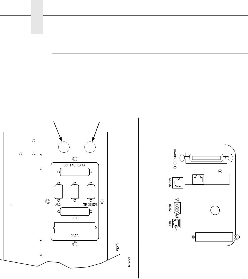
Figure 3. Interface Panels
1. Connect the pad home sensors mounted on the air cylinder to the pad
home port on the interface side panel. (Figure 3.)
2. Connect the interface cable to the serial data port.
3. Connect the opposite end of the interface cable to the serial
communications port of the host which will provide data.
4. Connect the product sensor connector to the trigger port.
NOTE: The I/O port is used to communicate with the SLPA’s GPIO inputs
and outputs if the optional fault/warning applicator control package is
installed.
5. If you have the IEEE-1284 parallel communications cable option, attach it
to the data port.
Beacon
Port Pad Home
Port
Interface Connections Between the
SLPA and External Equipment
Connections to the Controller Board
Air, Power, And Communications Connections
31
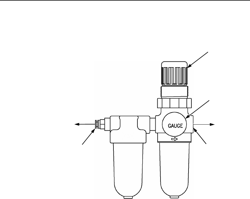
Figure 4. Air Filter
6. If you have a fault warning beacon, connect it to the beacon port.
(Figure 3.)
The fault warning beacon can also be mounted remotely from the SLPA.
(An optional 12 feet cable extension is available.)
7. Mount the air filter according to requirements.
NOTE: Customer must provide the necessary mounting for the air filter
supplied with the system.
8. Connect the air supply hose to the air supply connector marked IN.
(Figure 4.)
9. Connect the air hose to the quick connect air fitting marked OUT.
To Air
Supply
Hose
Air Hose to
SLPA
Air Pressure
Adjustment Knob
IN
Air Supply
Connector
OUT
Quick
Connect
Air Fitting
Air Pressure
Gauge
32
Chapter 1 Installing The SLPA
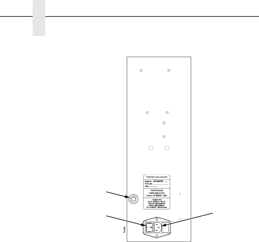
Figure 5. Power Panel
10. Connect the opposite end of the air hose to the quick connect air fitting on
the power panel. (Figure 5.)
NOTE: Make certain that all communication port parameters have been
configured according to purchase order requirements. Print
parameters must be programmed correctly to achieve the best
possible print quality. The factory settings are sufficient for most
applications. Refer to “Configuring The SLPA” on page 73 to
customize printing setup.
11. Adjust the air pressure to 90 ±10 psi using the air pressure adjustment
knob and the air pressure gauge (Figure 4): pull up the knob, then rotate it
clockwise to increase pressure or counterclockwise to decrease pressure.
Push in the knob when you have set the pressure.
12. If necessary, adjust the voltage (page 33).
13. Plug the AC power cord into the AC power receptacle. (Figure 5.)
14. Plug the SLPA and computer AC power cords into a grounded (three
prong) electrical outlet of the proper voltage.
15. Set the power switch to | (On) to power on the SLPA.
Quick
Connect
Air Fitting
Power Switch
AC Power
Receptacle
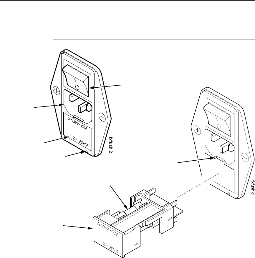
Adjusting The Voltage
33
Adjusting The Voltage
Figure 6. Adjusting the Voltage
The facing arrows indicate the selected voltage setting. (Figure 6.). If the
setting is incorrect, adjust the voltage as follows:
1. Set the power switch to O (Off).
2. Insert the tip of a flat tip screwdriver into the slot above the fuse holder
assembly, and twist to remove the assembly.
3. Flip over the fuse holder assembly and make sure the fuse is in the active
fuse location.
NOTE: Refer to “Electrical” on page 250 for fuse electrical specifications.
4. Reinsert the fuse holder assembly. Make sure the facing arrows are
aligned properly.
Facing
Arrows
Selected
Voltage
Power
Switch
AC Power
Receptacle
Fuse Holder
Assembly
Active Fuse
Slot

34
Chapter 1 Installing The SLPA
35
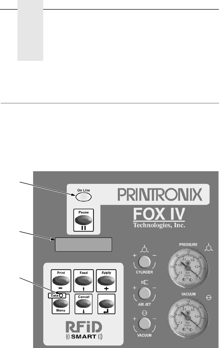
2Operation
Control Panel
The operation and system status of the SLPA are provided on the control
panel. Information concerning the SLPA is displayed on the liquid crystal
display (LCD), while commands are given to the SLPA through the control
panel keypad. Control valves are provided for refined adjustments to the
pneumatic system.
IMPORTANT
It is important to become familiar with all of the operations, readouts,
and components of the control panel. Inappropriate settings may impair
the SLPA’s functionality.
Figure 7. Control Panel
Online
Status
Indicator
Data
Indicator
Liquid
Crystal
Display
(LCD)

36
Chapter 2 Control Panel
LCD
The LCD is a 2 line by 16 character per line reflective display with a light
emitting diode (LED) backlight. The LCD displays system information on the
SLPA when performing system set-up procedures, print batch status during
operation, and system information in a fault condition.
Keypad
The keypad is used to place the SLPA in operation, to perform calibration or
testing, or to modify the systems operating parameters.
The keypad functions as two key groups: SLPA control when the SLPA is
online, and menu option setting when the SLPA is offline. The use of one key
group will not interfere with the use of the other key group. The function of
each indicator and key is defined in Table 1.
Table 1. Control Panel Keys
Indicator or
Key Description Online Mode Offline Mode Menu Mode
Online Status
indicator
Indicates when
SLPA is online,
offline, or in fault
condition.
Light is on when
online, ready to
print, and accept
data from host.
Flashes during
fault condition.
Light is off when
SLPA is offline.
Flashes during
fault condition.
Light is off.
Flashes during
fault condition.
Liquid Crystal
Display (LCD)
A 2 line by 16
character per
line reflective
display with a
light emitting
diode (LED)
backlight.
Displays
ONLINE, the
interface type,
and emulation in
use.
During a fault
condition,
displays specific
fault message
and required
action.
OFFLINE
During a fault
condition,
displays specific
fault message
and required
action.
Displays
OFFLINE, a
Main menu and
submenu, or
option.
During a fault
condition,
displays a
specific fault
message and
required action.
Pause key Switches the
SLPA between
online and
offline modes.
Pressing this
key when the
SLPA is online
takes the SLPA
offline.
Pressing this
key when the
SLPA is offline
places the SLPA
online.
Takes the SLPA
offline.

Keypad
37
1 Cancel Key must be set to Enable in the PRINTER CONTROL menu to use
the Cancel key. The default is Disable.
Print key Print key
– (decrease) key
in Menu mode.
Prints the next
label in the
buffer.
None Scrolls left
through current
menu options.
Decreases
option values in
submenus.
Feed key Feed key
↑ (up arrow) key
in Menu mode.
Advances the
media one label
length.
None Scrolls current
menu selection
up one level.
Apply key Apply key
+ (increase) key
in Menu mode.
Manually applies
the label.
Selects the
Printer Tests
menu, and then
scrolls through
the options.
Scrolls right
through current
menu options.
Increases option
values in
submenus.
Menu key
Data indicator
Menu key
Data indicator is
green when data
is in the system.
Takes the SLPA
offline and
selects Menu
mode.
Enters Menu
mode.
Scrolls through
the Main menu
selections.
Cancel key Pressing the
Cancel key will
enable the key
and clears all
data from the
print buffer and
prevent printing
of that data.1
↓ (down arrow)
key in Menu
mode.
None Clears all data in
the print buffer.
Scrolls the
current menu
selection down
one level.
↵ (Enter) key Pressing the ↵
(Enter) key in
Menu mode
selects the
displayed option
or value.
Selects the
Applicator Delay
menu
(page 195).
When in the
Printer Tests
menu, runs the
selected test.
Selects the
current menu
value.
Table 1. Control Panel Keys
Indicator or
Key Description Online Mode Offline Mode Menu Mode

38
Chapter 2 Control Panel
Key and Indicator Descriptions
For the locations of these keys and indicators, refer to Figure 7 on page 35.
Online Status Indicator
The SLPA is online when the Online status indicator light is on. When the
SLPA is offline, the light is off.
Pause Key
When the SLPA is online or in Menu mode, the Pause key takes the SLPA
offline (offline mode) and suspends all SLPA operations, but operations do
not cease until the current print or apply cycles have been completed. When
the SLPA is offline, the operator may make mechanical adjustments to the
SLPA, clear assembly line jams, etc., without powering off the system.
When the SLPA is offline, the Pause key places the SLPA back online (online
mode).
NOTE: The SLPA may automatically take itself offline in several situations
(e.g., out of labels, after recovering from a fault, etc.).
Print Key
When the SLPA is online, the Print key prints a label and feeds it to the
applicator pad if there is a label configuration in the SLPA’s print buffer. If no
label pattern exists in the buffer, it will not function.
In Menu mode, the – (decrease) key scrolls left through current menu options
or decreases option values in submenus.
NOTE: The Print key has no effect when the SLPA is offline.
Feed Key
When the SLPA is online, the Feed key advances the media one label length.
if the print buffer is currently empty. If the system is printing labels from the
buffer, this key will not function until the batch is done printing.
In Menu mode, the ↑ (up arrow) key scrolls the current menu selection one
level up.
NOTE: The Feed key has no effect when the SLPA is offline.
Apply Key
When the SLPA is online, the Apply key cycles the applicator as though the
SLPA was triggered by the product sensor. The cylinder extends to place the
label and a new label prints and is placed on the pad upon its return to the
home position.
In Menu mode, the + (increase) key scrolls right through current menu options
or increases option values in submenus.

Key and Indicator Descriptions
39
Menu Key and Data Indicator Light
When the SLPA is either online or offline, the Menu key takes the SLPA
offline and into Menu mode.
In Menu mode, the Menu key scrolls through the Main menu of the SLPA’s
operating system. It permits the operator to set or change various operating
parameters.
The Data indicator light on the Menu key is green when data is in the system.
This data refers to the information printed on the label. If the green light is off,
there is no data in the system. There is no manual operation of this indicator.
Cancel Key
NOTE: Cancel Key must be set to Enable in the PRINTER CONTROL menu
to use the Cancel key. The default is Disable.
When the SLPA is offline, the Cancel key clears the current print pattern and
all printing programs currently in the print buffer.
After clearing the print buffer, the SLPA automatically takes itself offline. The
SLPA may then have a new label pattern downloaded to the print buffer.
Press the Pause key to place the SLPA back online.
In Menu mode, the ↓ (down arrow) key scrolls the current menu selection one
level down.
↵
(Enter Key)
When the SLPA is online, the ↵ (Enter) key selects the Applicator Delay
Menu (page 195).
When the SLPA is offline, the ↵ (Enter) key is used to select a menu option,
or parameter value within the submenus. Press ↵ to select a menu option or
parameter.
In Menu mode, the ↵ (Enter) key selects the current value.
40
Chapter 2 Control Panel
Pneumatic Control Valves And Gauges
Air Cylinder Regulator
NOTE: You may also adjust the cylinder delay time through the Applicator
Delay menu. See “Applicator Delay Menu” on page 195.
The air cylinder regulator (CYLINDER valve) is used to regulate the air to the
applicator cylinder. The regulator setting affects how quickly the applicator
pad will extend (apply stroke) and return (return stroke) during the apply
cycle. This adjustment determines the force with which the applicator pad will
contact the product. If set too high, the applicator pad could contact the
product with enough force to cause damage. If set too low, the applicator pad
may not contact the product. The air pressure delivered for the apply stroke
and the return stroke is equal.
NOTE: Do not exceed 60 psi.
Monitor the setting of the air cylinder regulator using the PRESSURE gauge.
Air Jet Adjustment
The air jet adjustment (AIR JET) controls the air supply to the air jet tube. Air
is forced out the air jet tube allowing the labels to properly transfer over the
peel bar then to the applicator pad. If the adjustment is too low, the labels will
not properly transfer from the printer to the applicator pad. If set too high, the
label edge will be incorrectly positioned. The air jet is factory preset. Adjust
the air jet pressure by turning the AIR JET control clockwise to increase the
flow, counterclockwise to decrease the flow. See “Positioning The Air Jets” on
page 52.
Vacuum Adjustment
NOTE: You may also adjust the vacuum delay time through the Applicator
Delay Menu. See “Applicator Delay Menu” on page 195.
The vacuum adjustment (VACUUM) controls the amount of air flow through
the vacuum generator, thus determining the amount of vacuum holding the
label onto the applicator pad. A weak vacuum will cause labels to fall off of the
applicator pad prematurely. A vacuum that is too strong, however, can cause
difficulty when transferring the label onto the applicator pad and the product.
Vacuum is increased by rotating the valve clockwise and decreased by
rotating the valve counterclockwise.
NOTE: To get a vacuum on every label, every hole on the applicator pad
must be covered by the label surface.
Monitor the setting of the vacuum adjustment using the VACUUM gauge.
The minimum setting is 20 inches hg.
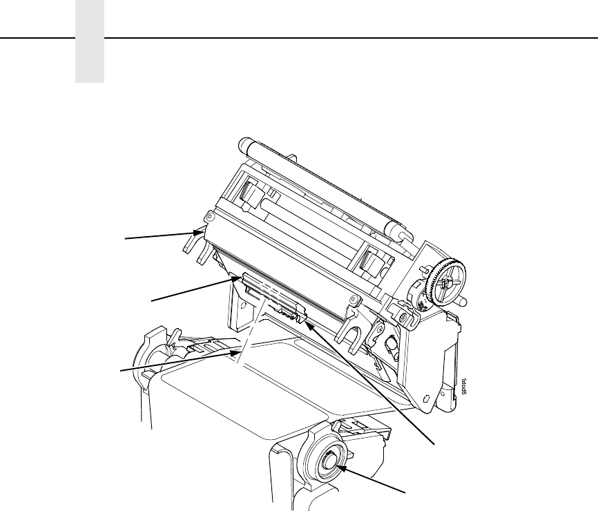
Threading The Label Roll
41
Setup
Threading The Label Roll
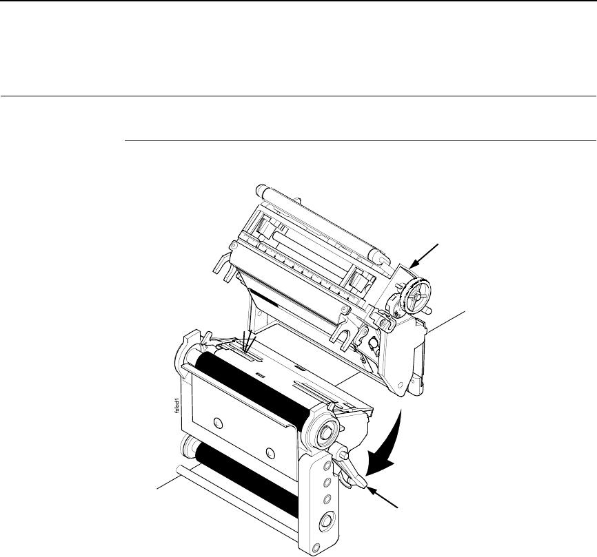
Figure 8. The Printhead Assembly
1. Press the Pause key to take the SLPA offline.
2. Open the pivoting deck by rotating the deck lock lever fully clockwise.
Pivoting Deck
Deck Lock Lever
42
Chapter 2 Setup
Figure 9. Mounting Label Media
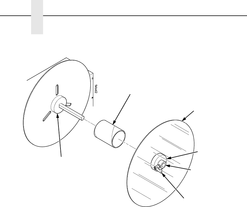
3. Loosen the cam lock located on the collar of the label roll hub.
4. Slide the label roll retainer off the label roll hub.
5. Remove the empty label roll core, if necessary, from the label roll hub.
Label Roll Core
Cam Lock
Label Roll Hub
Label Roll
Retainer
Collar
Label Roll Hub
Threading The Label Roll
43
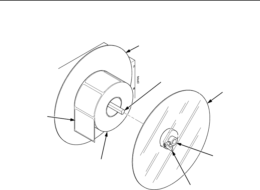
Figure 10. Loading Label Media
6. Slide the new label roll onto the label roll hub (unwinding
counterclockwise) and against the label roll back stop.
7. Angle the flat edge of the collar so that it aligns with the flat edge of the
label roll spindle.
8. Place the label roll retainer onto the label roll spindle until it is flush with
the label roll, then tighten the black cam lock.
NOTE: If necessary, loosen the set screw on the collar and adjust the core
blade so that it cuts into the label core.
Label Roll
Back Stop
Label Roll
Collar
Label Roll
Retainer
Cam Lock
Label
Label Roll
Spindle
44
Chapter 2 Setup
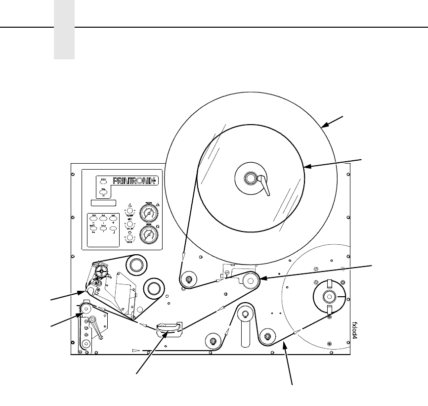
Figure 11. Loading Labels
9. Unwind approximately 3.0 feet (91cm) of media from the label roll. If your
label roll does not have a leader, remove the labels from the backing. The
empty backing (leader) will act as a leader to thread the media through
the SLPA components.
10. Pull the brake assembly away from the label roll back stop (behind the
label roll retainer) to release the tension.
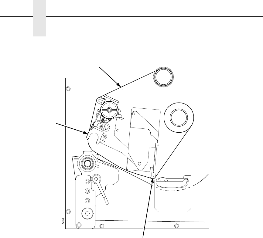
11. Thread the leader around the rollers and toward the media damper using
the solid white arrow threading diagram etched on the front center wall
plate.
Label Roll
Retainer
Brake
Assembly
Printhead
Platen
Media Damper
Backing (Liner) Path
Label Roll
Threading The Label Roll
45
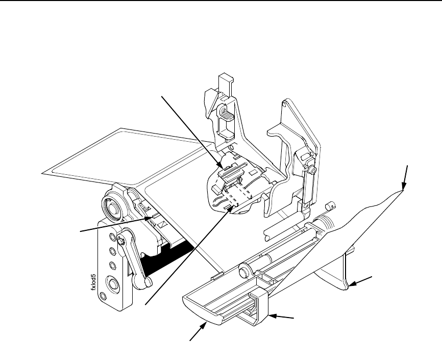
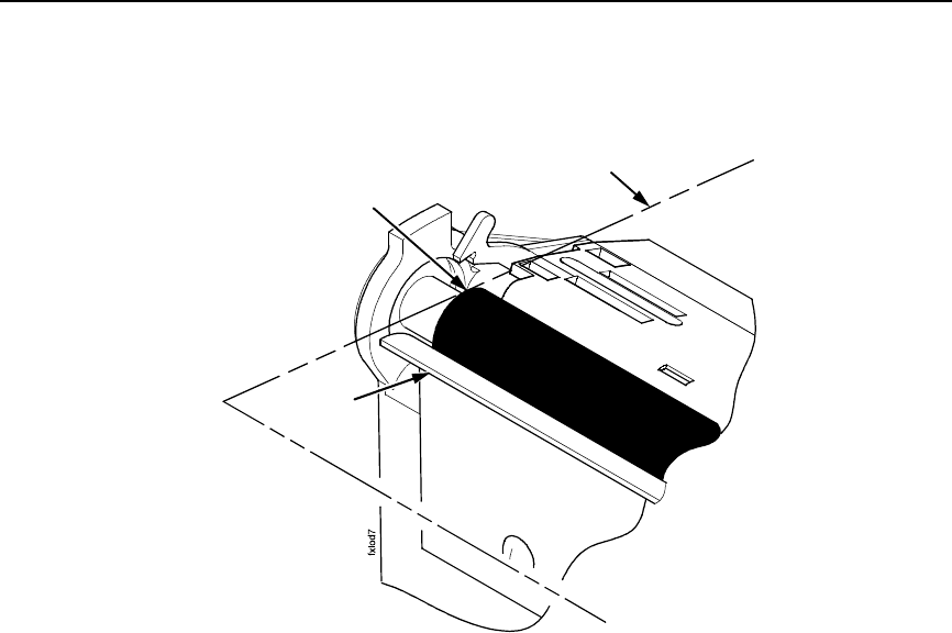
Figure 12. Threading Media Through the Printhead Assembly
12. Slide the media width guide close to the outside end of the media
damper.
13. Thread the leader under the media damper and then between the platen
(rubber drive roller) and the printhead.
14. Verify that the inside edge of the leader is against the fixed guide on the
bottom of the media damper.
15. Push the media width guide in until it is flush with the outer edge of the
media.
NOTE: Do not wrinkle the leader by pushing the media width guide too close
to the SLPA panel.
16. Check the horizontal position of the lower media sensor (located under
the media guard). See “Positioning The Media Sensors” on page 56.
Media Guard
Media Width
Guide
Media Damper
Fixed Guide
Lower Media
Sensor
Media Sensor
Handle
Leader
46
Chapter 2 Setup
Figure 13. Threading the Leader
17. Slide the upper sensor directly over the lower sensor.
18. Thread the leader between the printhead assembly and across the top of
the platen roller.
Upper Media
Sensor
Visible Red Beam
Lower Sensor
Upper Sensor
Handle
Platen Roller
Printhead
Assembly
Threading The Label Roll
47
Figure 14. Aligning Media
19. Align the inside edge of the media with the inside edge of the peel bar.
20. Thread the leader over the peel bar, then between the lower platen roller
and the air jet.
21. Follow the label guide arrows from the printhead, around the rollers to the
media rewind spool.
22. Fold the leading edge of the leader and insert it into the slit on the rewind
spool. Make sure the leader lines up closely to the SLPA panel.
23. Manually rotate the spool at least one turn counterclockwise.
NOTE: Hold the leader down while rotating the rewind spool to keep the
leader in place.
24. If the SLPA is being used in Thermal Transfer mode, it may be necessary
to load ribbon. See “Loading Ribbon” on page 49, otherwise proceed as
follows.
Platen
Media Edge
Peel Bar
48
Chapter 2 Setup
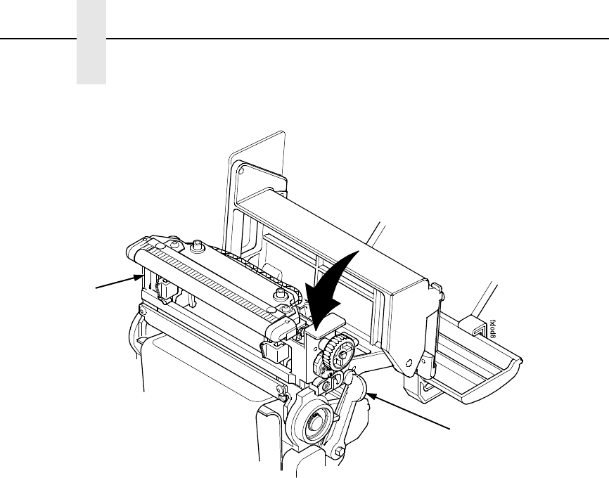
Figure 15. Locking the Pivoting Deck
25. Ensure that the label path is clear of obstructions, then close the pivoting
deck and rotate the deck lock lever fully counterclockwise. This locks the
pivoting deck and printhead assembly into the printing position.
IMPORTANT
Ensure the pivoting deck is down and locked before attempting to
advance media or print. Failure to do so will cause the PRINTHEAD UP
fault message to display.
26. Press the Pause key to place the SLPA online, and send a label format
via the host.
27. Feed two or three blank labels then place the SLPA online.
Pivoting Deck
Deck Lock
Lever
Loading Ribbon
49
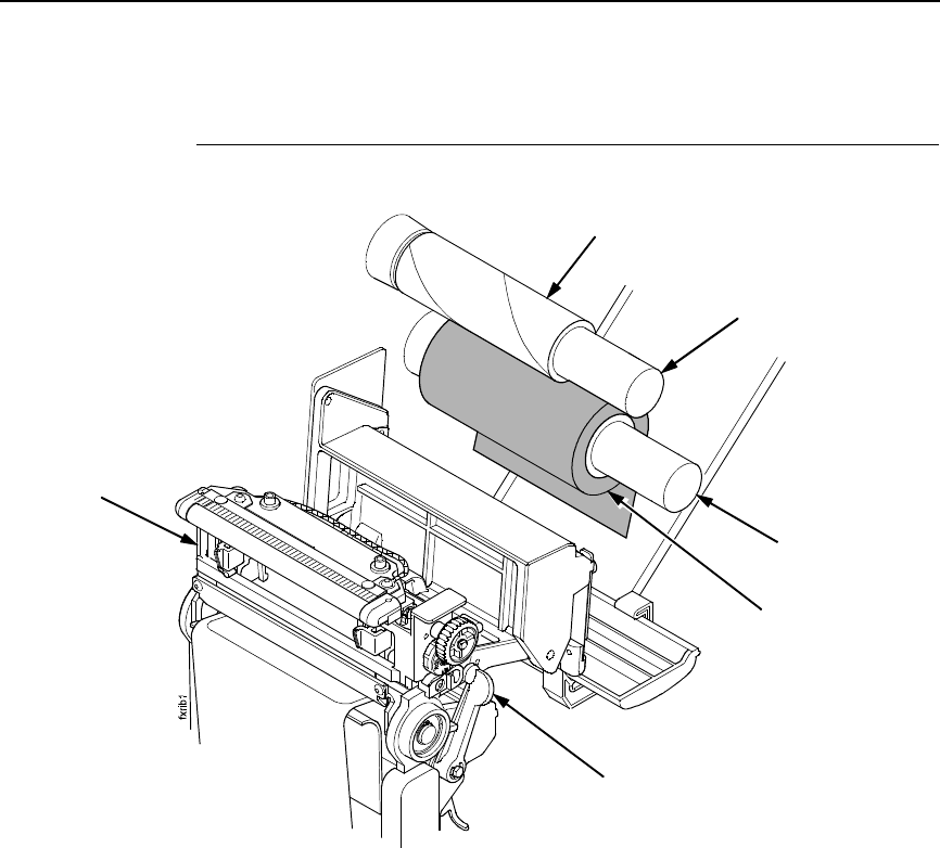
Loading Ribbon
Figure 16. Loading Ribbon
1. Press the Pause key to take the SLPA offline.
2. Install the ribbon take-up core on the ribbon take-up spindle.
NOTE: The first ribbon take-up fiberboard core comes with the SLPA.
Thereafter, use the fiberboard core from the old (used up) ribbon.
3. Slide the ribbon roll onto the ribbon supply spindle until it stops against
the spindle flange.
4. Open the pivoting deck by rotating the deck lock lever fully clockwise until
the deck swings upward.
Ribbon Take-Up Core
Ribbon Take-Up
Spindle
Ribbon Supply
Spindle
Ribbon Roll
Pivoting Deck
Deck Lock Lever
50
Chapter 2 Setup
Figure 17. Threading Ribbon Through the Printhead Assembly
5. Thread the end of the ribbon under the rear ribbon guide roller, then
between the platen and the printhead using the dotted line etched on the
front center wall plate.
Ribbon
Printhead
Rear Ribbon
Guide Roller
Loading Ribbon
51
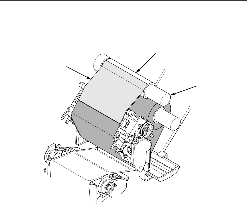
Figure 18. Attaching the Ribbon to the Take-up Core
6. Wrap the ribbon from the front of the printhead assembly to the top of the
ribbon take-up spindle. Attach the ribbon to the take-up core on the ribbon
take-up spindle with tape.
When installing a new roll of ribbon, attach the ribbon leader adhesive
strip to the ribbon take-up core. Manually rotate the spindle clockwise to
feed the unusable portion of the ribbon leader around the take-up spindle.
IMPORTANT
Do not attach the ribbon to the ribbon take-up spindle without a ribbon
take-up core installed.
7. Close the pivoting deck and rotate the deck lock lever fully
counterclockwise.
8. Press the Feed key once to verify that the media and ribbon advance.
9. Press the Pause key to place the SLPA online, then send a label format
via the host.
Ribbon
Take-up Core
Ribbon
Take-up Spindle
Ribbon
52
Chapter 2 Setup
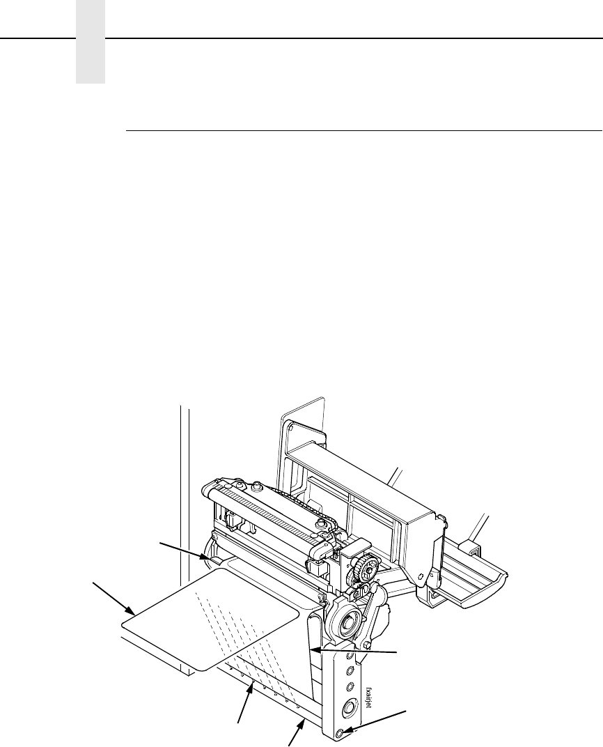
Positioning The Air Jets
When a printed label is being fed from the SLPA onto the applicator pad, it
must be held against the pad so that it can be properly positioned. The air jets
located on the air jet tube direct air at the label while it is being fed, so that it
does not bend or fall from the pad. Once proper positioning is achieved, the
vacuum of the applicator pad initiates and holds the label into place until
application.
For the air jets to work correctly, they must be directed at an angle specific to
the size of the label in use. Angle the air jets to a point which is approximately
1/3 the length of the current label length, as measured from the peel bar.
Wider or longer labels may approximate the air jet angle to a point beyond 1/3
the label length, where shorter or narrower labels may target inside the 1/3
length zone. Repeated adjustment may prove necessary for optimum
operation.
Figure 19. Positioning the Air Jets
The air jet will typically be adjusted for proper operation prior to being
shipped, but if further adjustments are necessary, proceed as follows:
1. Loosen the socket head screw holding the air tube into place.
2. Ensure that the proper holes in the air jet are open. The standard tube
comes with #6-32NC threaded holes and some of the holes may be
plugged with a small set screw. Add or remove set screws as necessary.
3. Turn the air tube adjustment so that the air jets are directed at
approximately 1/3 the length of the current label length as measured from
the peel bar.
4. Tighten the socket head screw into place to hold this adjustment.
Socket Head
Screw
Air Jet Tube
Air Jet
Label
Label Backing
Peel Bar

Removing Label Backing
53
Removing Label Backing
If the media rewind spool needs to be unloaded during operation, proceed as
follows:
1. Press the Pause key to take the SLPA offline.
2. Tear the label backing near the media rewind hub, then reach around the
rewound backing, placing your fingers behind the hub of the media rewind
spool.
3. Pull the rewind spool away from the centerwall plate until the rewind
release bars collapse toward the center of the hub, then pull off the used
label backing. The rewind hub will snap back into position near the
centerwall once the used label backing is removed.
4. Feed a few blank labels by inserting the new edge of the label backing
into the slit on the rewind spool and manually rotate the spool at least one
turn counterclockwise.
5. Press the Pause key to place the SLPA online.
SLPA System Configuration Parameters
The following is a list of the four system configuration parameters required for
the operation of the SLPA as an RFID label printer/applicator. They are Media
Handling, RFID Reader, GPIO Port, and GPIO Table.
NOTE: You may need to set or configure other parameters for proper SLPA
operation.
Media Handling
This item selects the method of media handling.
1. Press the Menu key to take the SLPA offline and into Menu mode.
2. Press the Menu key to scroll through the Main menu until QUICK SETUP
displays.
3. Press either the ↑ or ↓ key to scroll through the QUICK SETUP submenu
until Media Handling displays in the first line of the LCD.
4. Press the + or – key to scroll through the parameters until Tear Off
displays on the second line of the LCD.
5. Press the Enter key to select Tear Off.

54
Chapter 2 SLPA System Configuration Parameters
RFID Reader
This enables the RFID Reader.
1. Press the Menu key to take the SLPA offline and into Menu mode.
2. Press Menu key to scroll through the Main menu until RFID CONTROL
displays.
3. Press the ↑ or ↓ key to scroll through the RFID CONTROL submenu until
RFID Reader displays in the first line of the LCD.
4. Press the + or – key to scroll through the parameters until Enable displays
on the second line of the LCD.
5. Press the ↵ key to select Enable.
GPIO Control
Sets the required GPIO features (enable GPIO, select User Defined table
select, select Main table, enable Print and Apply).
1. Press the Menu key to take the SLPA offline and into Menu mode.
2. Press the Menu key to scroll through the Main menu until GPIO
CONTROL displays.
3. Press the ↑ or ↓ key to scroll through the GPIO CONTROL submenu until
GPIO displays in the first line of the LCD.
4. Press the + or – key to scroll through the parameters until Enable displays
on the second line of the LCD.
5. Press the ↵ key to select Enable.
6. Press the ↑ or ↓ key to scroll through the GPIO CONTROL submenu until
GPIO Sel. Table displays in the first line of the LCD.
7. Press the + or – key to scroll through the parameters until Main displays
on the second line of the LCD.
8. Press the ↵ key to select Main.
9. Press the ↑ or ↓ key to scroll through the GPIO CONTROL submenu until
GPIO Tables displays in the first line of the LCD.
10. Press the + or – key to scroll through the parameters until User Defined
displays on the second line of the LCD.
11. Press the ↵ key to select User Defined.
12. Press the ↑ or ↓ key to scroll through the GPIO submenu until GPIO
Print&Apply displays in the first line of the LCD.
NOTE: Admin User must be enabled in the Printer Control menu.
13. Press the + or – key to scroll through the parameters until Enable displays
on the second line of the LCD.
14. Press the ↵ key to select Enable.
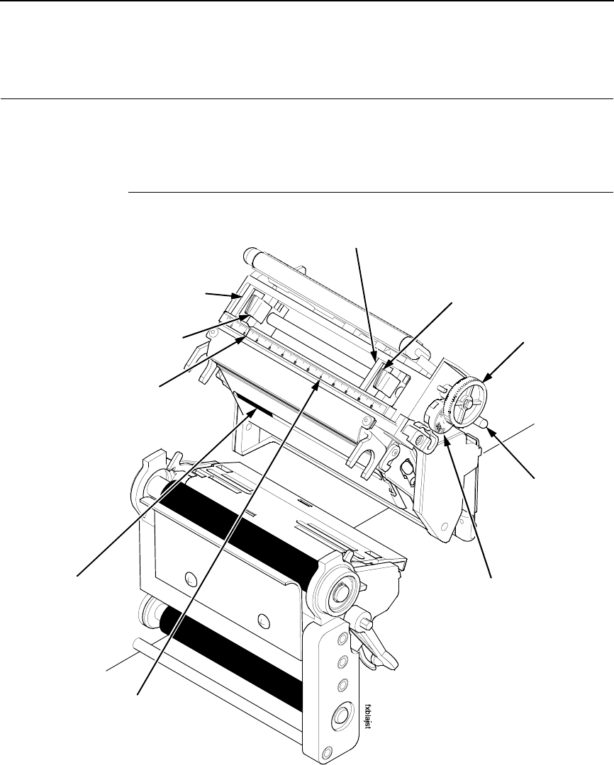
Printhead Pressure Adjustment
55
System Adjustments
This portion of the manual covers all general aspects of printhead and system
adjustment and replacement.
Printhead Pressure Adjustment
Figure 20. Printhead Pressure Adjustment
Adjust the printhead pressure to the setting of 4. The value shown at the
bottom of the dial is the active pressure setting.
Left Pressure
Block
Left Pressure
Block Handle
Bold Mark
Printhead Cover/
Upper Media
Sensor
Pressure Block
Adjustment Scale
Right Pressure Block
Right Pressure
Block Pointer
Lead Screw Knob
Printhead
Pressure
Adjustment Dial
Active Pressure
Setting
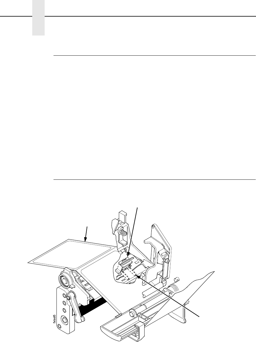
56
Chapter 2 System Adjustments
Printhead Pressure Block Adjustments
These adjustments to the left and right pressure blocks are typically made
when the print quality is not even across the surface of the label, and may be
necessary when replacing the printhead.
NOTE: Make no changes or adjustments while the SLPA is in operation.
Left Pressure Block
Manually adjust the left pressure block so its handle is aligned with the bold
mark on the pressure block adjustment scale.
Right Pressure Blocks
Use the lead screw knob to position the right pressure block with its pointer
near the right edge of the media in use.
Positioning The Media Sensors
Figure 21. Adjusting the Media Sensors
The SLPA is equipped with upper and lower media sensors that detect the
top-of-form position on media with label length indicators (black marks, gaps,
notches, or holes). These media sensors also detect Paper Out conditions.
Use the handles on the lower media sensor to horizontally position it so that
the left edge of the sensor’s visible red LED is aligned under the left edge of
the adhesive label of the installed media.
Adhesive Label
(left edge)
Lower Media Sensor
(left edge)
Lower Media
Sensor Handle (2)
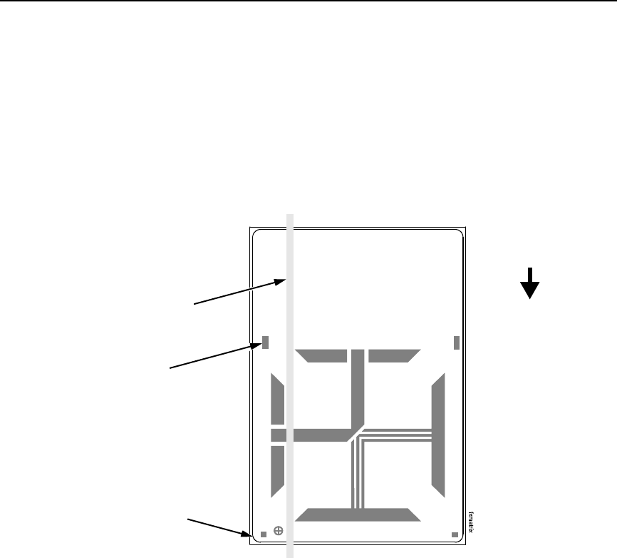
Positioning The Media Sensors
57
The upper media sensor, located in the slot under the printhead cover
(see Figure 20 on page 55), should be located directly over the lower media
sensor.
The lower media sensor should not be placed in the path of media features
that could cause false gap detection or paper out faults. Such features are
dark pre-printing, rounded die cut label corners, and extraneous cut-outs.
Figure 22. Positioning the Lower Media Sensor in Relation to the Label
Avoid Rounded
Die Cut Label
Corner
Position the lower
media sensor in the
grey shaded area.
Avoid Pre-Printing
FEED

58
Chapter 2 System Adjustments
Sensing Different Media Types
The SLPA’s media sensors can detect the different types of label length
indicators on a large variety of media types. This requires changes to the
Gap/Mark Sensor menu item in the CALIBRATE CTRL menu:
1. Press the Menu key to take the SLPA offline and into Menu mode.
2. Press ↓ and ↵ together until ENTER SWITCH UNLOCKED displays.
3. Press the Menu key until CALIBRATE CTRL displays.
4. Press ↓ until Gap/Mark Sensor / Disable* (the currently enabled option)
displays.
5. Press + or – until the option that matches the type of label length
indicators on the installed media displays:
•Disable. The default. Select when using media with no label length
indicators (no black marks, gaps, notches, or holes) or
when you
want the SLPA to ignore all existing label length indicators on the
installed media. See instructions below.
NOTE: When you select Disable, the length of each label is based on the
Label Length value entered in the QUICK SETUP menu or the value
sent via host software.
•Mark. Select when using media that has horizontal black marks
located on the underside of the label liner or tag stock. See page 59.
•Gap.
Select
when using media with a liner space between die cut
labels or when using tag stock with notches or holes as label length
indicators on white background media. See page 60.
•Advanced Gap. Select when using media that has liner gaps
between die cut labels with a black background. See page 61.
•Advanced Notch. Select when using media with notches or holes
that interrupt a black vertical line on the underside of the media.
See page 62.
NOTE: If the SLPA detects a false paper out message when you change
from Advanced Gap or Advanced Notch to Gap or Mark sensing or
vice versa, press the Pause key and run Auto Calibrate (page 63).
6. Press ↵ to enable the displayed option. An asterisk (*) appears next to
the selection.
7. Press Pause until OFFLINE displays.
8. Review “Calibrating The Media Sensors” on page 63.
9. Perform the Auto Calibrate procedure on page 63.
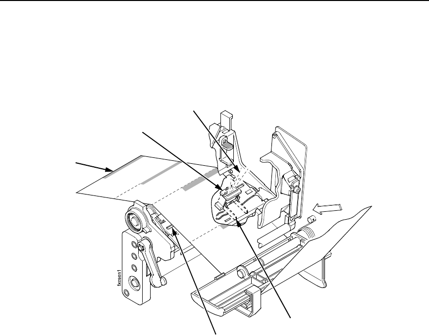
Sensing Different Media Types
59
Sensing Media with Horizontal Black Marks (Mark)
Figure 23. Media with Horizontal Black Marks
Position the lower media sensor for detecting horizontal black marks located
on the underside of media.
1. Check the position of the sensor by looking through the long, narrow
opening in the media guard. Use the visible red light emitting from the
lower sensor as a reference pointer.
2. Use the sensor handle to manually position the sensor as close as
possible to the center of the black mark on the media.
3. Set Gap/Mark Sensor to Mark in the CALIBRATE CTRL menu. See
“Sensing Different Media Types” on page 58.
4. Perform the Auto Calibrate procedure on page 63.
Lower Sensor
Media Guard
Opening
Black Mark
(underside
of media)
Sensor Handle
Visible Red Beam
from Lower Sensor
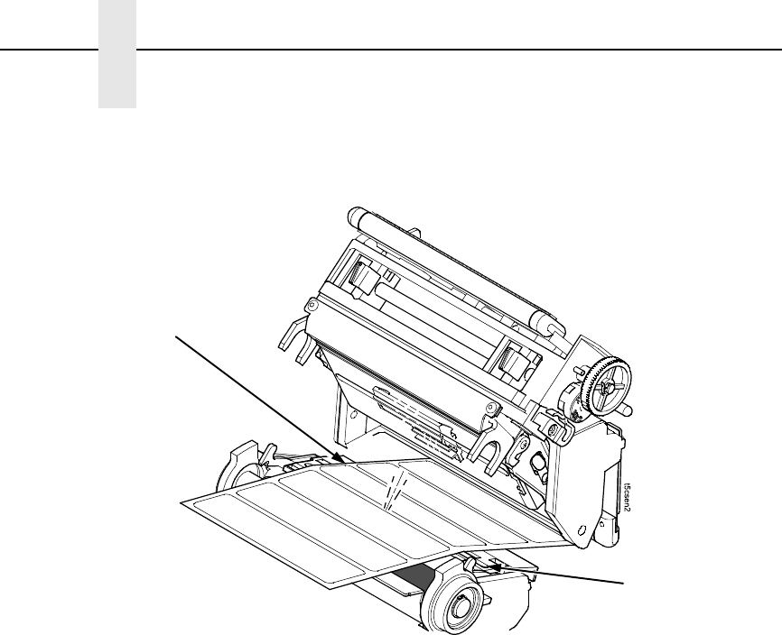
60
Chapter 2 System Adjustments
Sensing Media with Gaps, Notches, or Holes (Gap)
Figure 24. Media with Gaps, Notches, or Holes
Position the lower media sensor for detecting gaps, notches, or holes in
media with a white background. Place the upper sensor above the lower
sensor to provide a consistent background.
1. Position the lower sensor directly under the center of the gap, notch, or
hole.
2. Check the position of the lower sensor by looking through the long,
narrow opening in the media guard. Use the visible red light emitting from
the lower sensor as a reference pointer.
3. Use the sensor handle to manually position the sensor to the center of the
gap, notch, or hole in the media.
4. Set Gap/Mark Sensor to Gap in the CALIBRATE CTRL menu. See
“Sensing Different Media Types” on page 58.
5. Perform the Auto Calibrate procedure on page 63.
Media Guard
Opening
Visible Red Beam
from Lower Sensor
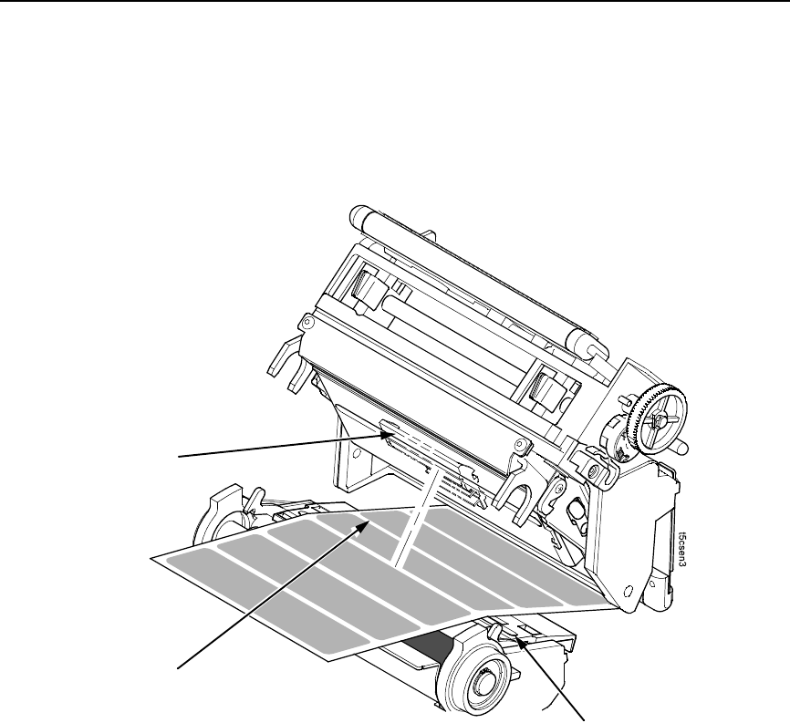
Sensing Different Media Types
61
Sensing Media with Dark Background Labels with Gaps
(Advanced Gap)
Figure 25. Dark Background Media with Gaps
NOTE: Ribbon is not displayed in this illustration. The upper and lower
sensors are designed to function with or without ribbon installed.
The upper sensor and lower sensor are used together to detect liner gaps
between die cut labels that have a black or dark background on white or clear
liner.
1. Position the lower sensor so that the left edge of the beam is slightly to
the right of the left edge of the die cut label directly under the center of the
gap.
2. Check the position of the lower sensor by looking through the long,
narrow opening in the media guard. Use the visible red light emitting from
the lower sensor as a reference pointer.
3. Set Gap/Mark Sensor to Advanced Gap in the CALIBRATE CTRL menu.
See “Sensing Different Media Types” on page 58.
4. Perform the Auto Calibrate procedure on page 63.
Media Guard
Opening
Visible Red Beam
Lower Sensor
Fixed Upper Sensor
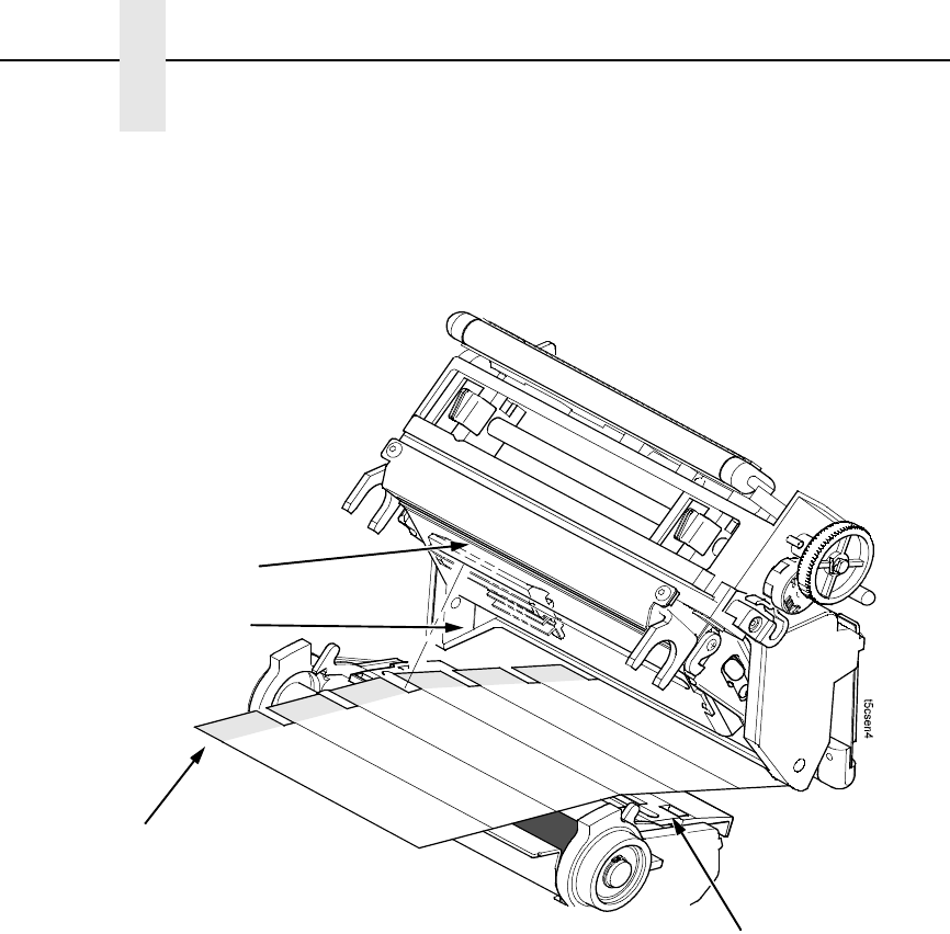
62
Chapter 2 System Adjustments
Sensing Dark Background Media with Notches or Holes
(Advanced Notch)
Figure 26. Dark Background Media with Notches or Holes
NOTE: Ribbon is not displayed in this illustration. The upper and lower
sensors are designed to function with or without ribbon installed.
The upper sensor and lower sensor are used together to detect notches or
holes in media with a black or dark underside. This combination can be found
on tag stock that has a black vertical line along one edge on the underside of
the label, interrupted by a notch or hole used as the label length indicator.
1. Position the lower sensor so that the left edge of the beam is slightly to
the right of the left edge of the die cut label directly under the center of the
notch or hole.
2. Check the position of the lower sensor by looking through the long,
narrow opening in the media guard. Use the visible red light emitting from
the lower sensor as a reference pointer.
3. Set Gap/Mark Sensor to Advanced Notch in the CALIBRATE CTRL
menu. See “Sensing Different Media Types” on page 58.
4. Perform the Auto Calibrate procedure on page 63.
Visible Red Beam
Lower Sensor
Media Guard
Opening
Fixed Upper Sensor
Black line
on underside
of media

Calibrating The Media Sensors
63
Calibrating The Media Sensors
Due to manufacturing differences in media and ribbon, the media sensors
may have difficulty differentiating between the label and the liner or the label
and the black mark. When this occurs, the SLPA may intermittently skip a
label or display a fault message such as GAP NOT DETECTED / See Manual
or PAPER OUT / Load Paper.
Media sensor sensitivity and reliability can be improved by changing the
Gap/Mark Threshold and/or Paper Out Threshold values. You can change
these values automatically by performing the Auto Calibrate or Manual
Calibrate procedure in the CALIBRATE CTRL menu or change them manually
by entering your own Gap/Mark Threshold or Paper Out Threshold values.
(The changes take effect immediately within the current configuration menu.)
Auto or Manual Calibrate is completed successfully when the displayed
Sensed Distance value correctly matches that of the installed media. When
Gap is selected, the Sensed Distance value should match the length from the
trailing edge of one gap to the trailing edge of the next gap (or one label + one
gap). When Mark is selected, the Sensed Distance value should match the
length from the leading edge of one black mark to the leading edge of the next
black mark.
When you have completed Auto or Manual Calibrate, you can verify that the
new values are correct by pressing the Feed key several times. Each time you
press Feed, media advances one label and stops at the correct Top-of-Form
position of the next label.
Once you confirm the correct values, save them to the desired configuration
menu before powering off the SLPA. See “Saving A Configuration” on
page 75.
Running Auto Calibrate
You can initialize Auto Calibrate via the Apply key (described in detail below)
or via the CALIBRATE CTRL or DIAGNOSTIC menus in Menu mode.
NOTE: Verify that the Gap/Mark Sensor option (Disable, Mark, Gap,
Advanced Gap, or Advanced Notch) matches the installed media.
See “Sensing Different Media Types” on page 58.
Check that the media sensors are horizontally positioned to permit
sensing of the label length indicators. See “Positioning The Media
Sensors” on page 56.
If you try to do an Auto Calibrate when Peel-Off Media Handling is
enabled, the LCD will display CANNOT CALIBRATE / Disable Peel-
Off. Before you can do an Auto Calibrate, you must select another
media handling mode.
1. Press the Pause key until OFFLINE displays on the LCD.
2. Press ↓ and ↵ together until ENTER SWITCH UNLOCKED displays.
3. Press the Apply key until Printer Tests / Auto Calibrate displays.
4. Press ↵. Media advances until it can accurately detect the label length
indicators and then stops at the Top-of-Form position. The Sensed
Distance value will then display for one second.

64
Chapter 2 System Adjustments
5. Auto Calibrate is successful when the Sensed Distance value correctly
matches that of the installed media:
•Gap/Mark Sensor = Gap, Advanced Gap, or Advanced Notch:
The Sensed Distance value is the physical length of one label plus
the length of one gap, notch, or hole.
•Gap/Mark Sensor = Mark: The Sensed Distance value is the
physical distance from the leading edge of one black mark to the
leading edge of the next.
•Gap/Mark Sensor = Disable: Not applicable. If Gap/Mark Sensor is
set to Disable, the Sensed Distance value will not be updated.
If GAP NOT DETECTED displays, run Auto Calibrate again.
If Auto Calibrate continues to end with an incorrect Sensed Distance
value displayed or a fault message displayed, run Manual Calibrate as
described on page 66.
NOTE: The amount of media sampled during Auto Calibrate is based on the
length of a label and transitions detected, without error, between a
label and its label length indicators.
6. Press the Pause key until OFFLINE displays.
7. Press the Feed key several times. Each time you press Feed, the media
advances one label length and stops.
NOTE: After a form feed, the position of the leading edge of the next label
depends on the type of Media Handling mode selected under the
QUICK SETUP menu. Tear-Off and Tear-Off Strip Media Handling
will position the label edge at the peel bar, while Continuous will
position the label edge under the printhead.
8. Press the Pause key until ONLINE displays.
9. Once the Sensed Distance value is confirmed, save it to the desired
configuration (page 75) before powering off the SLPA.

Calibrating The Media Sensors
65
Running Media Profile
The Media Profile printout shows the relationship of the Paper Out Threshold
and the Gap/Mark Threshold values, illustrates if and when each label length
indicator is detected, and shows the difference between the label length
indicators and the label. The profile printout (see Figure 27 on page 66) helps
you set the thresholds for difficult media. This includes pre-printed labels and
labels with poor gap/media dynamic range.
Once Media Profile is initiated, the SLPA will continue to advance media and
print the profile in landscape orientation until you press ↵ to stop printing.
NOTE: Verify the CALIBRATE CTRL menu Gap/Mark Sensor option
(Disable, Mark, Gap, Advanced Gap, or Advanced Notch) matches
the installed media. See “Sensing Different Media Types” on page 58.
You will need a minimum installed label width of two inches to support
the Profile printout.
Ensure the lower media sensor is horizontally positioned to permit
sensing of the label length indicators. See “Positioning The Media
Sensors” on page 56.
Ensure the Print Mode option selected in the QUICK SETUP menu
matches the media installed. Select Direct for heat sensitive media
(no ribbon required) or Transfer for thermal transfer media (ribbon
required).
1. Press the Menu key to take the SLPA offline and into Menu mode.
2. Press ↓ and ↵ together until ENTER SWITCH UNLOCKED displays.
3. Press the Menu key until PRINTER CONTROL displays.
4. Press ↑ until Admin User displays.
5. Press + until Enable displays.
6. Press ↵ to select Enable. An asterisk (*) appears next to Enable.
7. Press Menu until GPIO CTRL displays.
8. Press ↓ until GPIO Print&Apply displays.
9. Press + until Disable displays.
10. Press ↵ to select Disable. An asterisk (*) appears next to Disable.
11. Set Continuous Mode in the Media Handling menu.
66
Chapter 2 System Adjustments
12. Press Menu until CALIBRATE CTRL displays.
13. Press ↓ until Media Profile / Profile Print displays and then press ↵. (The
SLPA will continue to print the profile until you press ↵.)
The SLPA will advance media and continue to print a dynamic profile
image depicting the relationship of the label and any label length
indicators detected.
14. Press ↵. The SLPA will stop printing.
15. Press Menu until GPIO CTRL displays.
16. Press ↓ until GPIO Print&Apply displays.
17. Press + until Enable displays.
18. Press ↵ to select Enable. An asterisk (*) appears next to Enable.
19. Press the Pause key until OFFLINE displays.
NOTE: The Gap/Mark and Paper Out Threshold values shown on the Profile
printout represent the last values determined from a successful Auto
or Manual Calibrate or the factory default values if no Auto or Manual
Calibrate was performed.
Figure 27. Media Profile Printout
Running Manual Calibrate
Manual Calibrate should be performed only when the values derived from
Auto Calibrate fail to improve the media sensors’ ability to sense label length
indicators on the installed media. You must first enable Admin User in the
PRINTER CONTROL menu before accessing or initializing Manual Calibrate
in the CALIBRATE CTRL menu.
NOTE: Verify the Gap/Mark Sensor option (Gap, Mark, Advanced Gap,
Advanced Notch, or Disable) matches the installed media. See
“Sensing Different Media Types” on page 58.
255
191
127
063
000
Paper Out(144)
Gap Mark(105)

Calibrating The Media Sensors
67
Ensure the media sensors are horizontally positioned to permit
sensing of the label length indicators. See “Positioning The Media
Sensors” on page 56.
Ensure the Print Mode option selected in the QUICK SETUP menu
matches the media installed. Select Direct for heat sensitive media
(no ribbon required) or Transfer for thermal transfer media (ribbon
required).
If you try to do a Manual Calibrate when Peel-Off Media Handling is
enabled, the LCD will display, CANNOT CALIBRATE / Disable Peel-
Off. Before you can do a Manual Calibrate, you must select another
media handling mode.
1. Press the Menu key to take the SLPA offline and into Menu mode.
2. Press the ↓ and ↵ keys together until ENTER SWITCH UNLOCKED
displays.
3. Press the Menu key until PRINTER CONTROL displays.
4. Press ↑ until Admin User displays.
5. Press + until Enable displays.
6. Press ↵ to select Enable. An asterisk (*) appears next to Enable.
7. Press the Menu key until CALIBRATE CTRL displays.
8. Press ↓ until Manual Calibrate / Run Calibrate displays, then press ↵.
9. Follow the instructions displayed on the LCD. Example: REMOVE
RBN&MEDIA / Press Enter indicates that you must open the pivoting
deck and remove the ribbon and media from under the printhead, close
and lock the pivoting deck, and press the ↵ key.
During the last step of Manual Calibrate, the SLPA will advance the media
and attempt to detect the label length indicators and stop at the Top-of-
Form position. The Sensed Distance value will then display for one
second. The calibrate is successful when the Sensed Distance value
correctly matches that of the installed media.
If CALIBRATION FAIL / See Manual displays, run Manual Calibrate
again.
NOTE: The amount of media sampled during Manual Calibrate is based on
the length of a label and the transitions detected without error,
between a label and its label length indicators.
10. Press the Pause key until OFFLINE displays.
11. Press the Feed key several times. Each time you press Feed, the media
advances one label length and stops.
NOTE: After a form feed, the position of the leading edge of the next label
depends on the type of Media Handling mode selected under the
QUICK SETUP menu. Tear-Off and Tear-Off Strip Media Handling
positions the label edge at the peel bar, while Continuous positions
the label edge under the printhead.
12. Once the correct values are confirmed, save them to the desired
configuration (page 75) before powering off the SLPA.

68
Chapter 2 Printing And Applying Labels
Printing And Applying Labels
WARNING
Printronix has provided the necessary guards and warnings within the
confines of the SLPA, but cannot anticipate each customer’s individual
installation and operational environments. It is the customer’s
responsibility to provide in-house safety guards to provide adequate
worker safety for their respective production settings.
WARNING
An input signal from the product sensor will activate the SLPA when the
SLPA is online unless it is taken offline.
This section provides a brief overview of the print and apply process as well
as suggested steps preliminary to printing.
During power-up, the SLPA performs a self-diagnostic test and indicates if the
system has any existing fault or warning conditions.
Once the SLPA is online and configured (if necessary) for the desired
application, take the SLPA offline before downloading labels from the host
into the buffer. This will prevent any chance of having the system cycle before
you are prepared to begin print operations.
For information on the proper setup of the SLPA, see “Setup” on page 41.
Label Application (Positioning) Adjustments
To apply the labels at the desired location on the product:
1. Mount the product sensor on the side of the conveyor, determining if the
sensor should be mounted upstream from the applicator pad (product
passes sensor before pad) or downstream from the applicator pad
(product passes pad before sensor), depending on the application.
IMPORTANT
Mount the product sensor appropriate to the position where you would
like the label to be applied. It is easier to position the label onto the
product using the sensor delay when the sensor is mounted upstream
from the applicator pad.
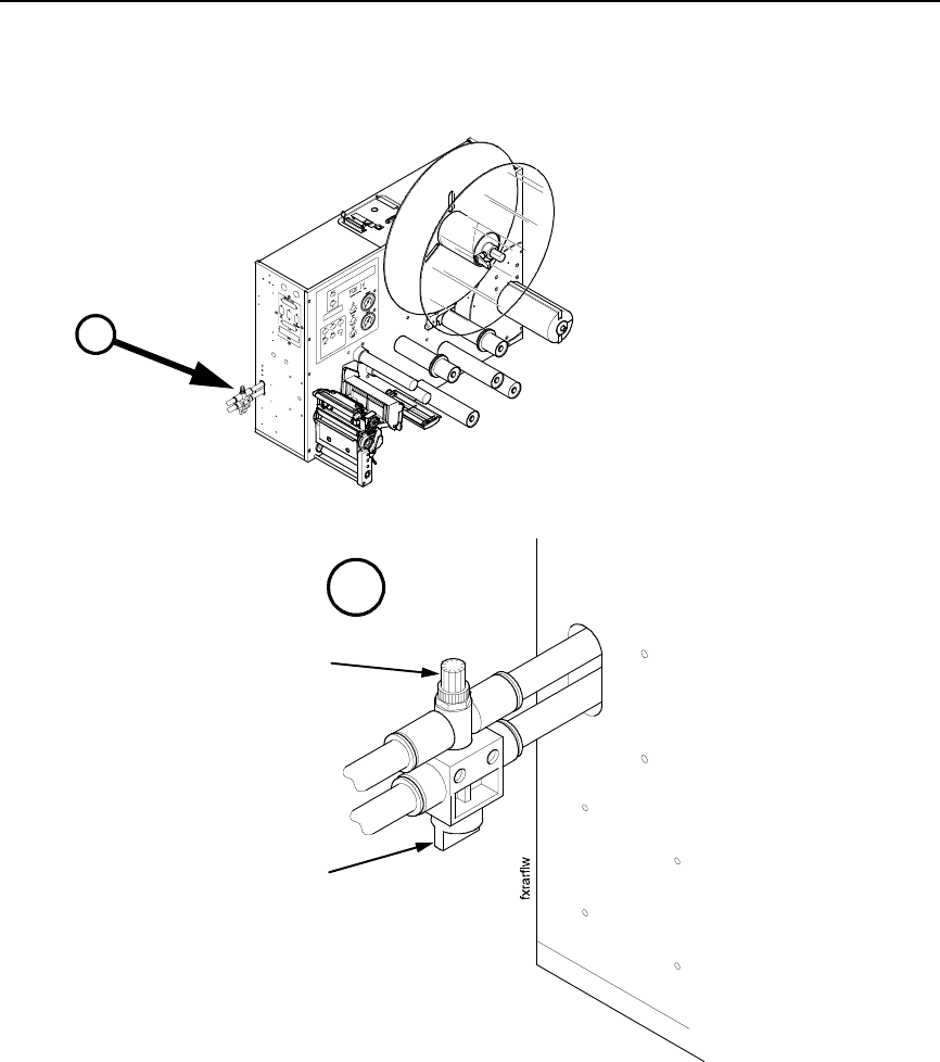
Label Application (Positioning) Adjustments
69
Figure 28. Return Speed Control Valve
2. Set the Cycle Delay time for the product sensor using the Applicator
Delay menu. (See “Applicator Delay Menu” on page 195.)
NOTE: The Cycle Delay setting determines the amount of delay from the
time that the product sensor detects the product to the time that the
applicator pad is online. Since the label prints first, be sure to account
for printing time. The longer the time entered, the farther back (closer
to the trailing edge) the label will be placed onto the product.
Conversely, if this value is set to zero, for example, the applicator pad
will launch as soon as the label is printed.
Begin by setting the Cylinder Extend time to 10 msec to begin this
adjustment procedure. (See “Applicator Delay Menu” on page 195.)
A
A
Flow Control
Valve
Tamp Cylinder Air
Shut Off Valve

70
Chapter 2 Printing And Applying Labels
3. Place the product sample on the conveyor and allow it move past the
SLPA. The label that is applied will be used as a reference point for
positioning the rest of the labels.
4. To move the label toward the leading edge of the product, decrease the
Cycle Delay time. Begin by decreasing the time in intervals of 10 msec,
then fine tune in intervals 1 msec. Repeat this procedure until the label is
positioned where desired.
5. To move the label toward the trailing edge of the product, increase the
Cycle Delay time. Begin by increasing the time in intervals of 10 msec,
then fine tune in intervals 1 msec. Repeat this procedure until the label is
positioned where desired.
If the label still cannot be positioned properly, remount the product sensor as
follows:
1. To position the label toward the leading edge of the product, move the
product sensor upstream.
2. To position the label toward the trailing edge of the product, move the
product sensor downstream.
3. Once the label is positioned in the desired location on the product, secure
the product sensor onto the conveyor.
If the SLPA cycles when a product is not in position, a background object may
be activating the sensor. To correct this problem, reposition the product
sensor or adjust the product sensor. See “Product Sensor” on page 259 for
more information on product sensor adjustments.
WARNING
Interrupting the signal on the product sensor will activate the SLPA.
Make certain that the path of the applicator path is clear.
Adjusting The Cylinder Extend Time
NOTE: Remember that the supply air pressure to the SLPA should be
80 to 100 psi (550 to 690 kPa). Set the cylinder pressure to 40 psi to
start.
1. Set the Cylinder Extend time using the Applicator Delay menu.
(See “Applicator Delay Menu” on page 195.)
NOTE: The amount of time the applicator pad is energized through the
cylinder extend time, determines how far the pad travels during
application of the label. The longer the time entered, the farther the
distance the applicator pad travels. If this value is set to zero, for
example, the applicator pad will not launch.
Set the Cylinder Extend time to 110 msec to begin this adjustment
procedure.

The Print And Apply Process
71
•If the applicator pad does not contact the product (if the stroke time is not
long enough):
Increase the Cylinder Extend time using the Applicator Delay menu.
Begin by increasing the time in intervals of 10 msec, then fine tune in
increments of 1 msec. A higher setting allows the applicator pad more
time to extend toward the product, therefore, increasing the stroke
length.
•If the applicator pad remains on the product for too long (if the stroke time
is too long):
Decrease the Cylinder Extend time using the Applicator Delay menu.
Begin by increasing the time in intervals of 6 msec, then fine tune in
increments of 1 msec. A lower setting decreases the amount of time
that the applicator pad is extended (in contact with the product).
2. Use the flow control valve (located on the air cylinder) to adjust the speed
of the return stroke. (Figure 28.) Increase the speed by rotating the valve
counterclockwise and decrease the speed by rotating the valve
clockwise.
The Print And Apply Process
Before labels can be printed and applied:
1. Ensure that the protective guards are properly secured and that materials
are clear of the applicator pad and printhead assembly.
2. Ensure that you have input time values for Cycle Delay, Cylinder Extend,
and Vacuum Delay (if applicable). (See “Applicator Delay Menu” on
page 195.)
NOTE: The applicator will not move unless a value is entered for Cylinder
Extend.
3. Press the Pause key on the control panel to enable the product sensor, or
to allow remote signals received through the interface package option to
activate the SLPA.
NOTE: You may wish to cycle several labels onto product samples, to ensure
proper operation of the SLPA.

72
Chapter 2 Printing And Applying Labels

73
3Configuring The SLPA
IMPORTANT
Changing system parameters can affect SLPA operation and could
disable it. Thoroughly review this chapter, as inappropriate settings may
impair the SLPA’s functionality.
Setting Printer Configuration Parameters
Configuration parameters are set from the control panel or are retrieved from
the printer’s memory. The parameters define how the SLPA will respond to
command and interface signals from the host computer.
The configuration menu structure consists of main menus and the options
applicable to each menu.
NOTE: Some configurations refer to SLPA options that may not be present in
your SLPA. If you select an option or feature that is not present, no
action will be performed by the SLPA or an “OPTION NOT
INSTALLED” message will display on the LCD.
Moving Within The Configuration Menu
You can move through the configuration menus using the appropriate
navigation keys. (See “Control Panel” on page 35 for more details on the
function of the control panel keys.)
You can select different options and save them as the power on default;
however, you can only save them to configuration menus 1 to 8. The factory
configuration menu can be altered, but not saved.
When the SLPA is online, the first line of the LCD displays “ONLINE” and the
second line lists the active interface port and type of emulation.
To configure the SLPA:
1. Press the Menu key to enter take the SLPA offline and enter Menu mode.
2. You can move through configuration main menus in two ways:
•Press the Menu key to move to the right.
•Press the + key to move right or the – key to move left.
NOTE: In menus with numeric ranges of more than 50 numbers, hold down
the + or – key for more than 2 seconds to move through the range in
increments of 5. To move in increments of 1 again, release your hold
on the + or – key.

74
Chapter 3 Moving Within The Configuration Menu
Selecting A Menu Option
To select an option, you need to press the ↵ key. By default, however, the
↵ key is “locked” when the printer is turned on to prevent accidental changes
to the configuration menu. If you press the ↵ key when the key is locked, the
message “ENTER SWITCH LOCKED” displays on the LCD for one second
and the value will not be selected.
To unlock the ↵ key, press the ↓ and ↵ keys at the same time. This toggles
the ENTER/LOCK function.
•If this function is performed while the ↵ key is locked, the message
“ENTER SWITCH UNLOCKED” displays for one second, and the ↵ key
will be unlocked.
•If this function is performed while the ↵ key is unlocked, the message
“ENTER SWITCH LOCKED” displays for one second, and the ↵ key will
be locked.
When you press the ↵ key (with the ↵ key unlocked), you select the value or
option that displays. An asterisk displays after the value you selected, and the
configuration is changed immediately.
IMPORTANT
This change takes effect for all subsequent data and operations for the
printer as soon as the ↵ key is pressed and the asterisk (*) is displayed.
The configuration change(s) stay in effect only while the printer is
powered on. When the power is turned off, all current configurations will
be lost unless changes made to it are saved via the CONFIG. CONTROL
menu.
To save configuration information permanently or to select it as the power-up
default, see “Saving A Configuration” on page 75.
Changing Printer Settings
You can change (or “configure”) printer settings, such as print speed or
emulations, through the control panel as follows:
1. Press the key until the following message displays:
2. Press the ↓ key to cycle through these options:
•Print Intensity
•Print Speed
•Print Mode
•Media Handling
•Paper Feed Shift
•Label Length
•Label Width
MENU MODE
QUICK SETUP
.
.
.

Saving A Configuration
75
•Ver Image Shift
•Hor Image Shift
•Orientation
•Gap/Mark Sensor
•Auto Calibrate
•Save Config.
•Power-Up Config.
3. When the desired submenu displays, press the + or – key to scroll
through the values or options.
4. Press the ↵ key to select a value. An asterisk (*) displays next to the
selected value or option.
5. If there are more submenu values or options you want to change, use the
, ↑, ↓, +, and – keys to access the value and the ↵ key to select it. At
any time, you may press the key to return to the Main menu.
6. At any time, you may press the PAUSE key twice to exit the Configuration
menu and place the printer online. Once you have finished selecting all
your options, save your configuration.
IMPORTANT
If you do not save your configuration, all your new values will be lost
when you power off the printer.
Saving A Configuration
You can save up to eight different configurations to meet eight unique print job
requirements. These configurations are saved and stored in the printer and
are not lost when the printer is turned off.
NOTE: If the Protect Configs. option is enabled, the new configuration will not
be saved until the existing configuration is deleted.
Follow these steps to save a new configuration:
1. Press the key until the following message displays:
2. Press the ↓ key until the following message displays:
3. Press the + or – key to cycle through the options (1-8). Note that “Factory”
is not listed, because no changes made to the factory configuration can
be saved under Factory.
.
.
..
.
.
.
.
.
MENU MODE
CONFIG. CONTROL
Save Config.
1*