Printronix ADMP2PA Print and Apply Machine User Manual PTX UM SLPA7000r 250117A
Printronix Inc Print and Apply Machine PTX UM SLPA7000r 250117A
UserManual.wiki
>
Printronix
>
ADMP2PA User Manual
>
Users Manual 2
Contents
1.
Users Manual 1
2.
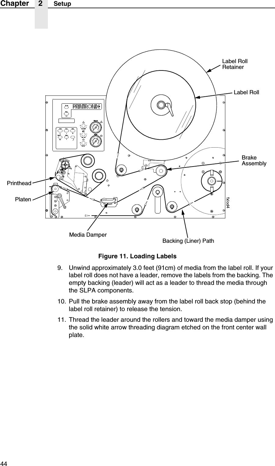
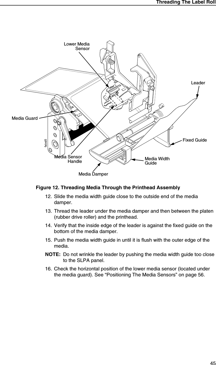
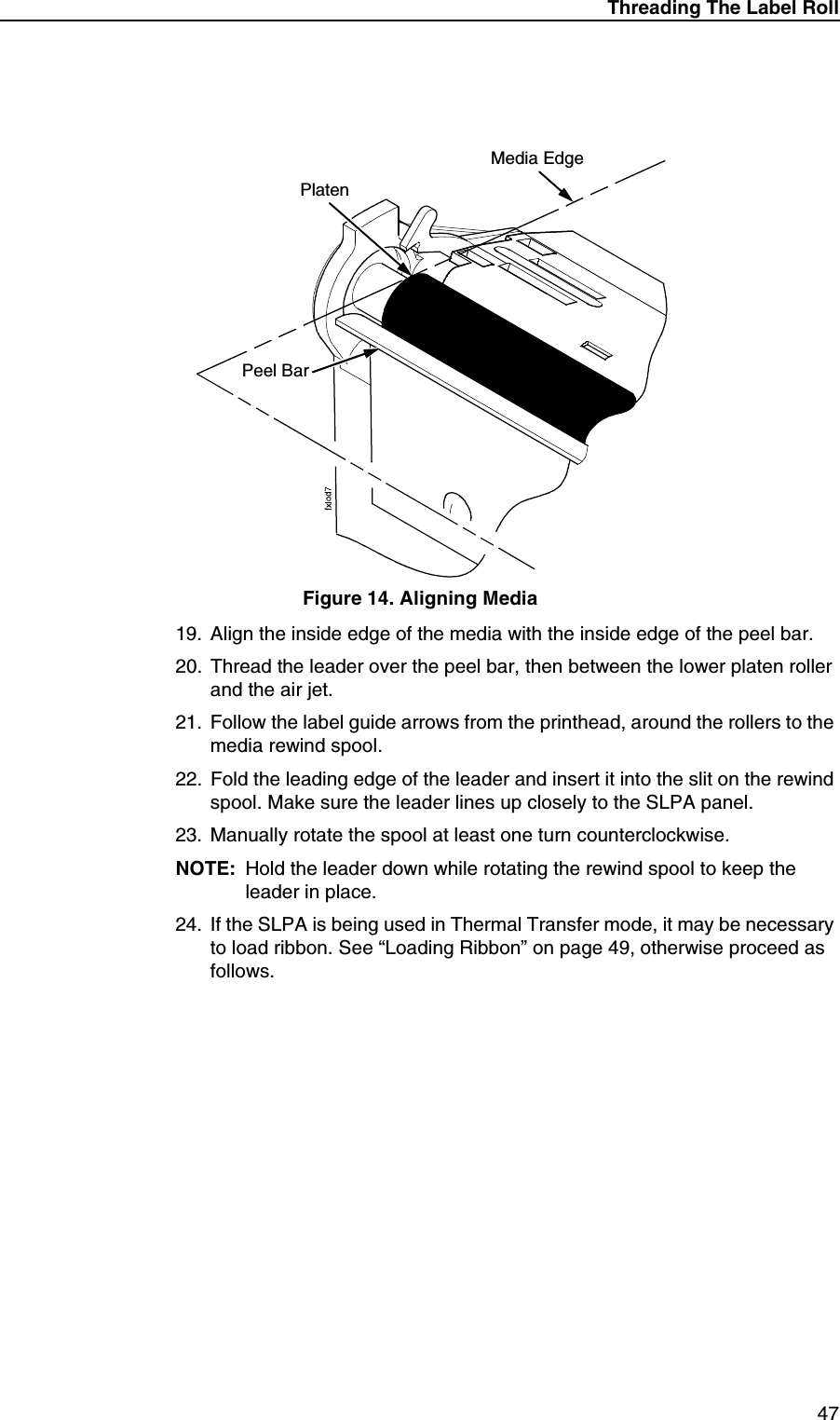
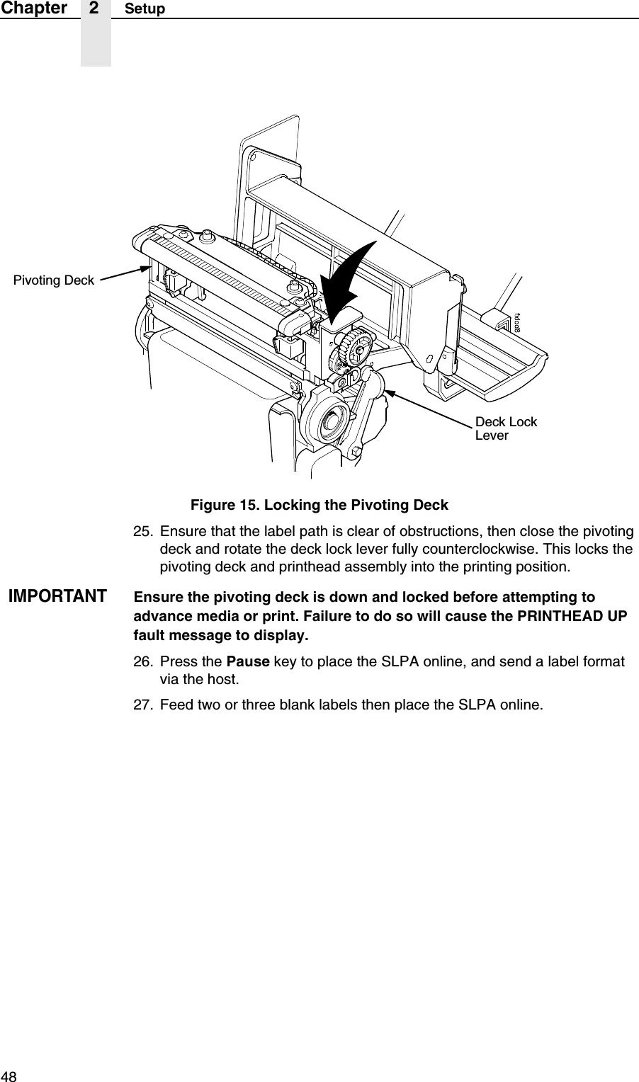
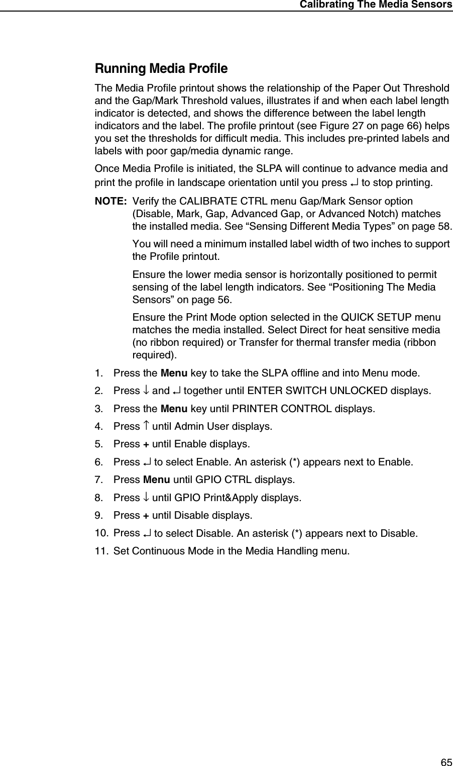
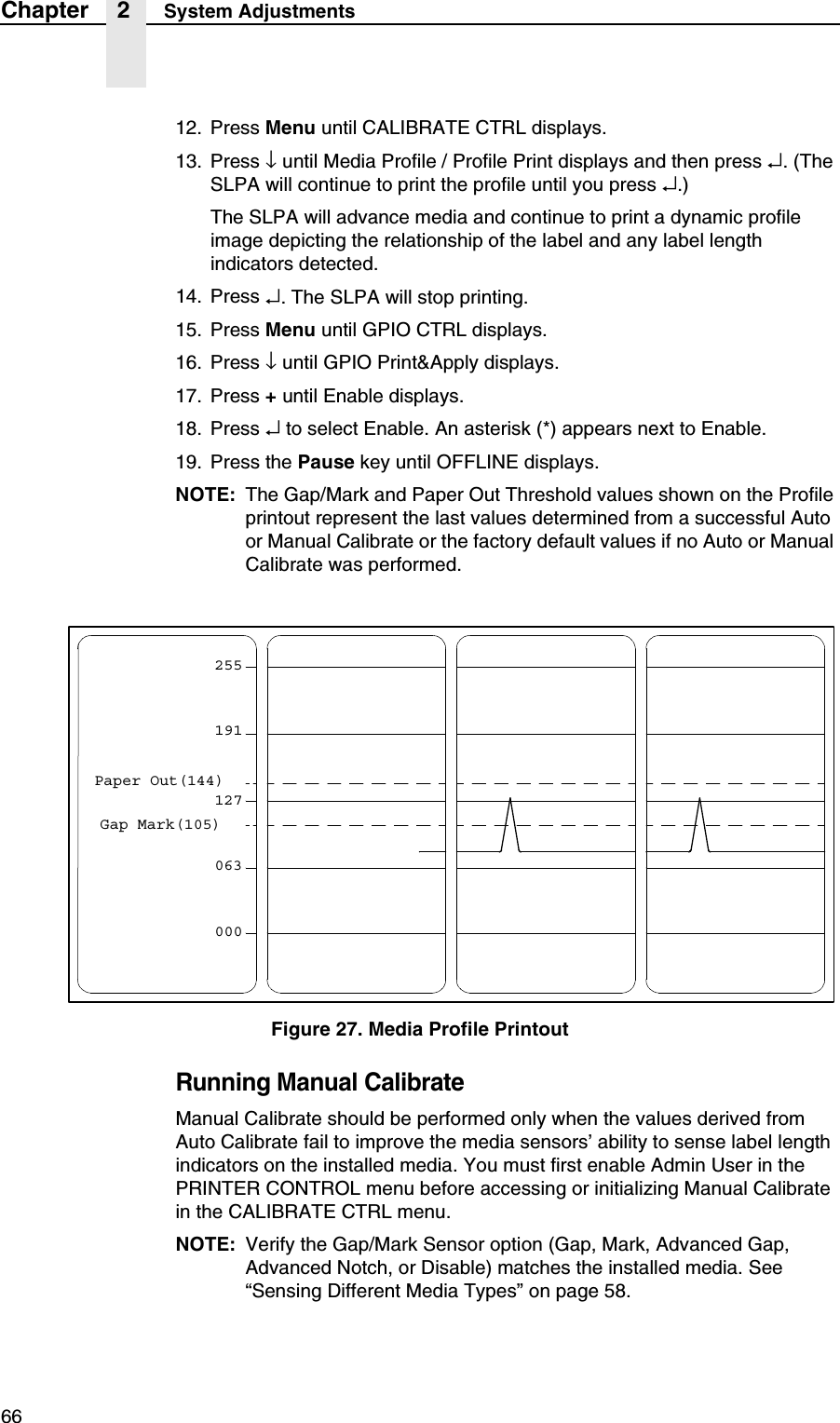
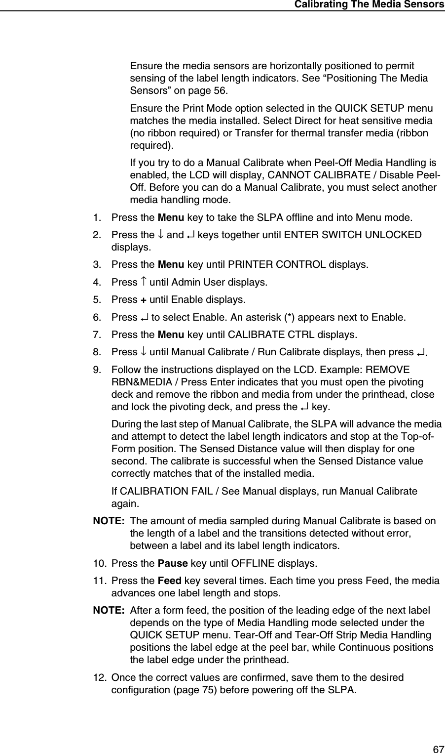
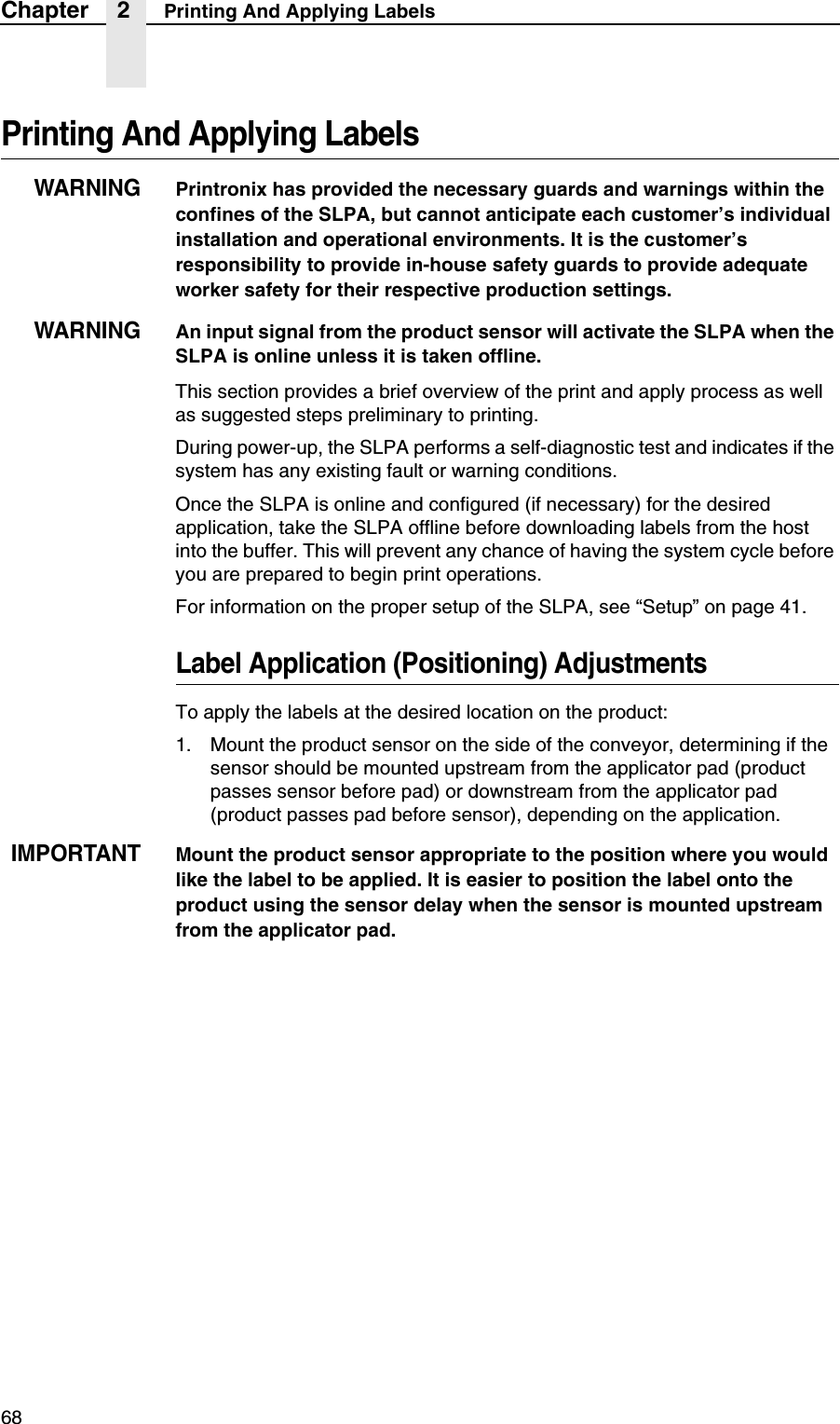
Users Manual 2
3.
Users Manual 3
Users Manual 2
Navigation menu
Upload a User Manual
Namespaces
Wiki Guide
HTML
PDF
Info
Views
User Manual
Discussion / Help
Navigation