Printronix ADMP2PA Print and Apply Machine User Manual PTX UM SLPA7000r 250117A
Printronix Inc Print and Apply Machine PTX UM SLPA7000r 250117A
UserManual.wiki
>
Printronix
>
ADMP2PA User Manual
>
Users Manual 3
Contents
1.
Users Manual 1
2.
Users Manual 2
3.
Users Manual 3
Users Manual 3
Navigation menu
Upload a User Manual
Namespaces
Wiki Guide
HTML
PDF
Info
Views
User Manual
Discussion / Help
Navigation
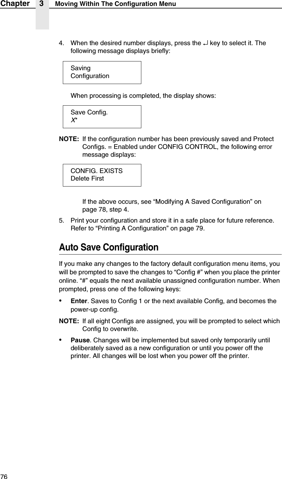

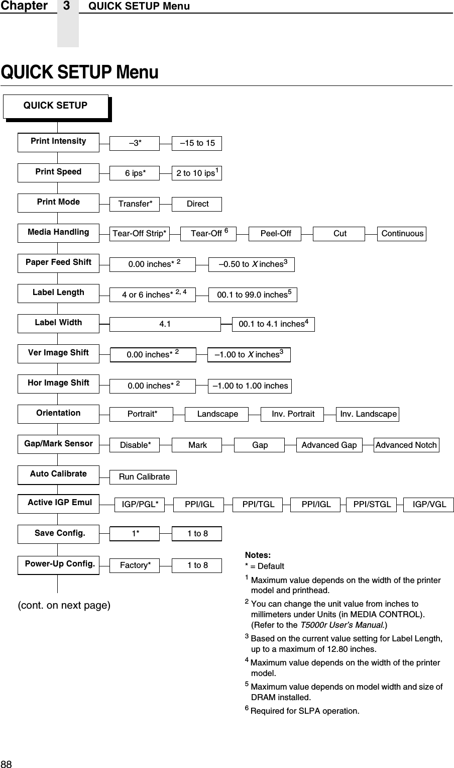
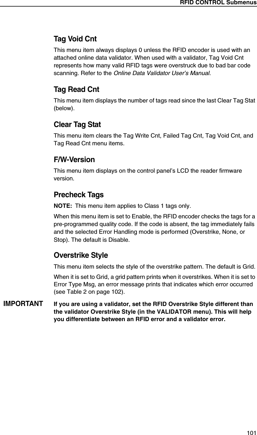
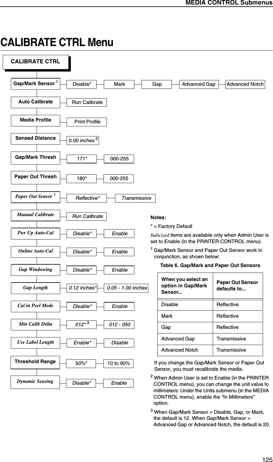
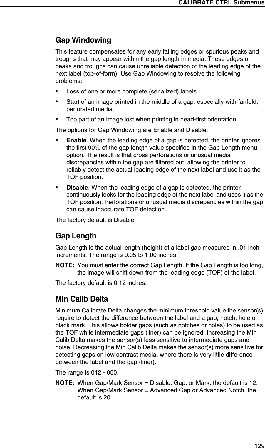
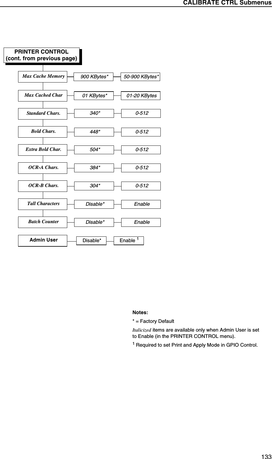
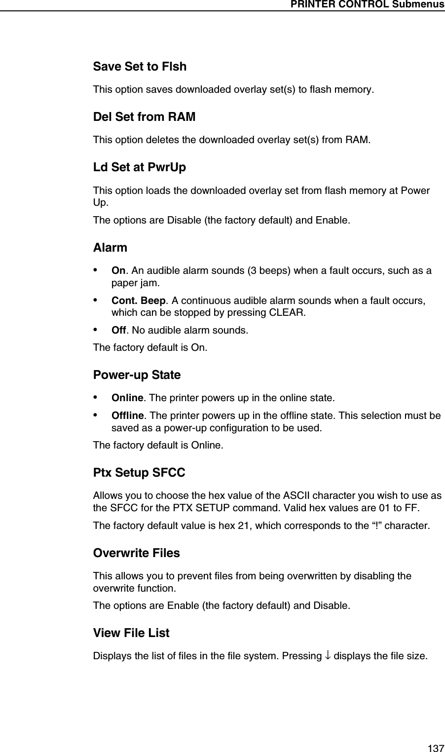
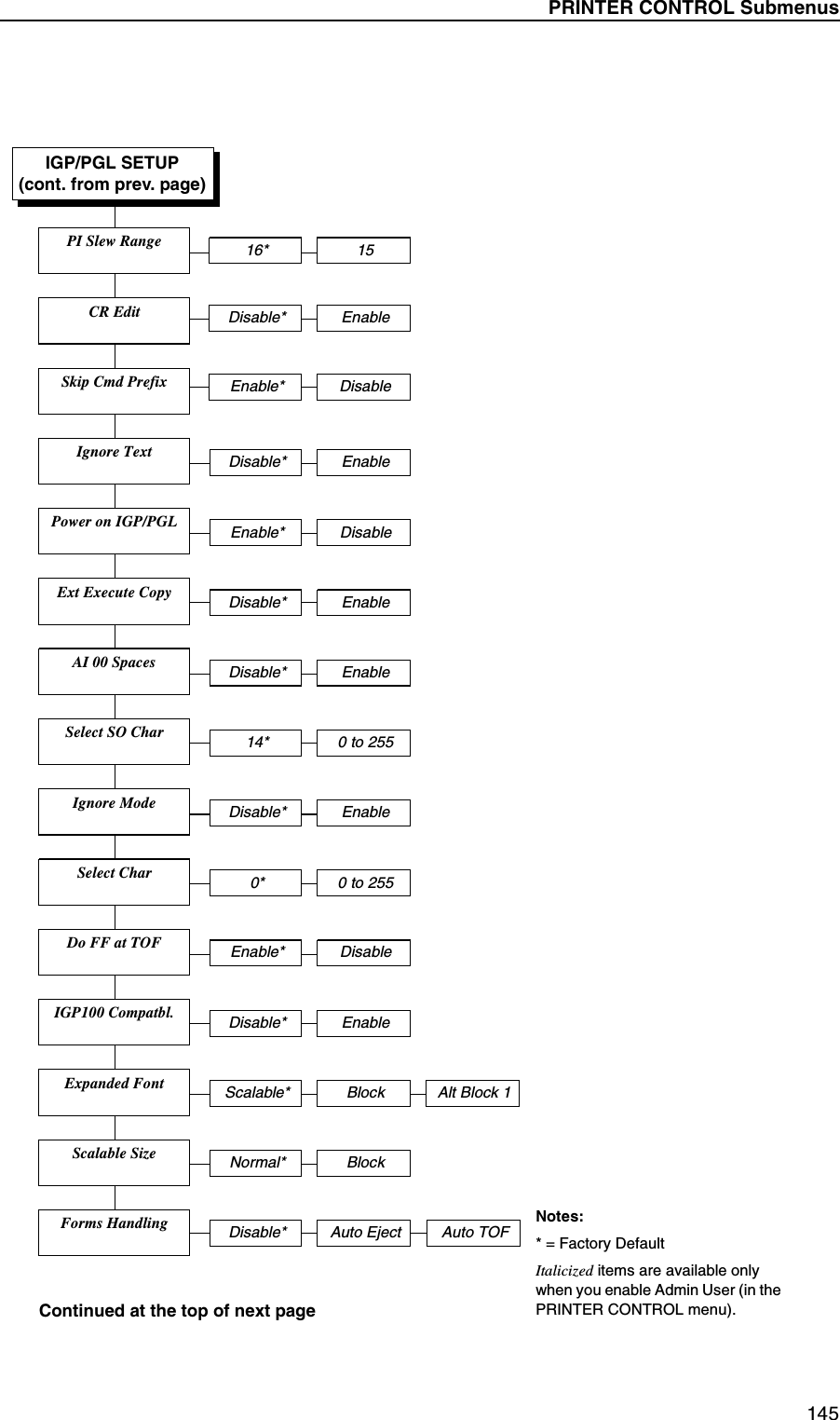
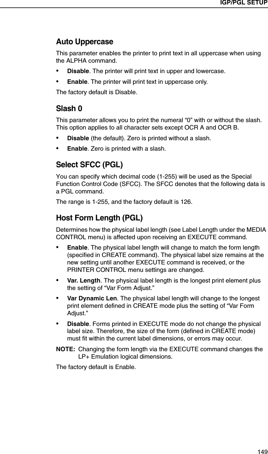
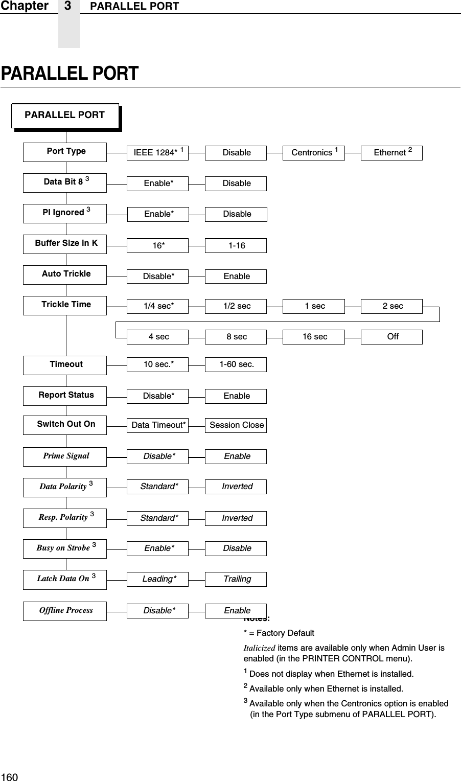
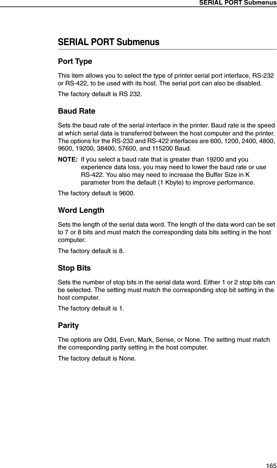
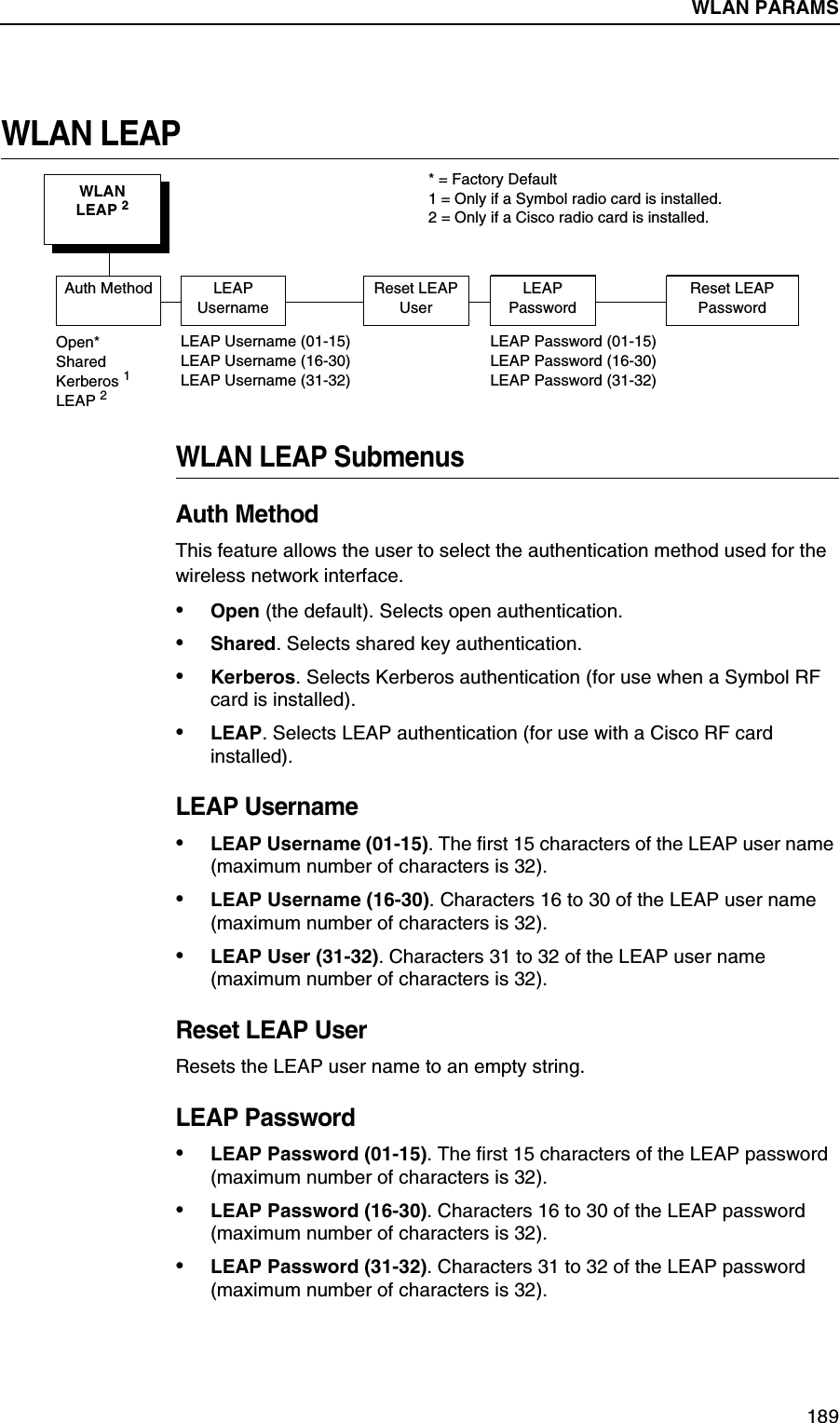
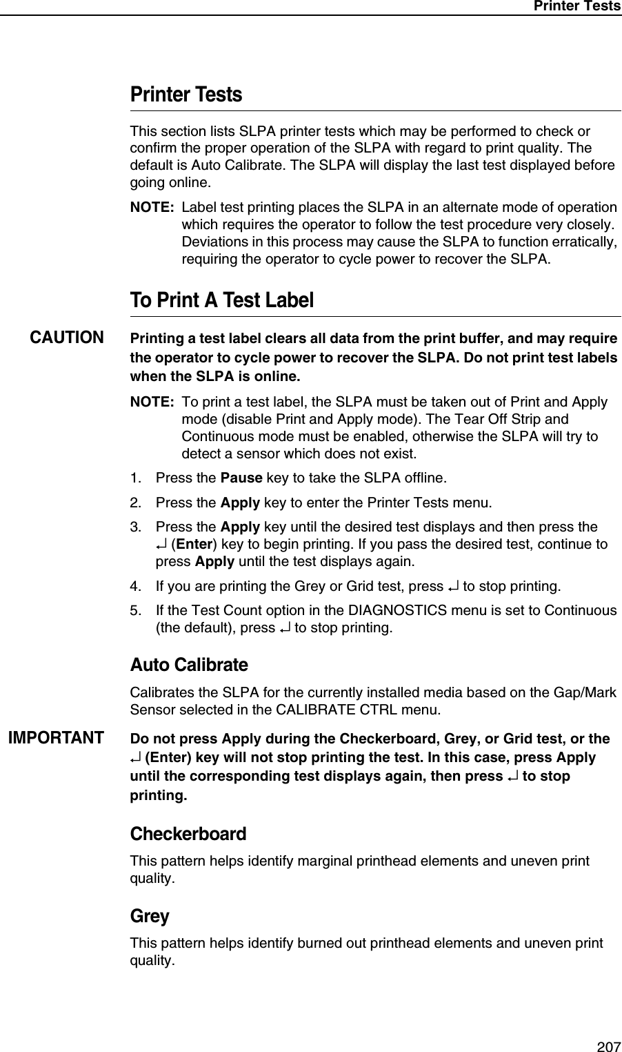
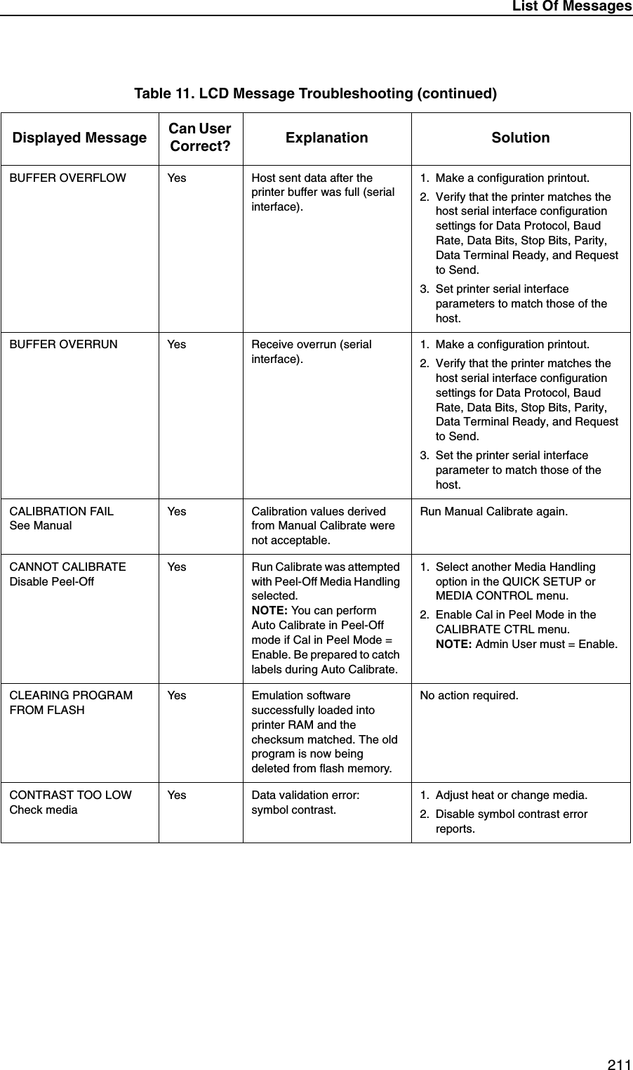
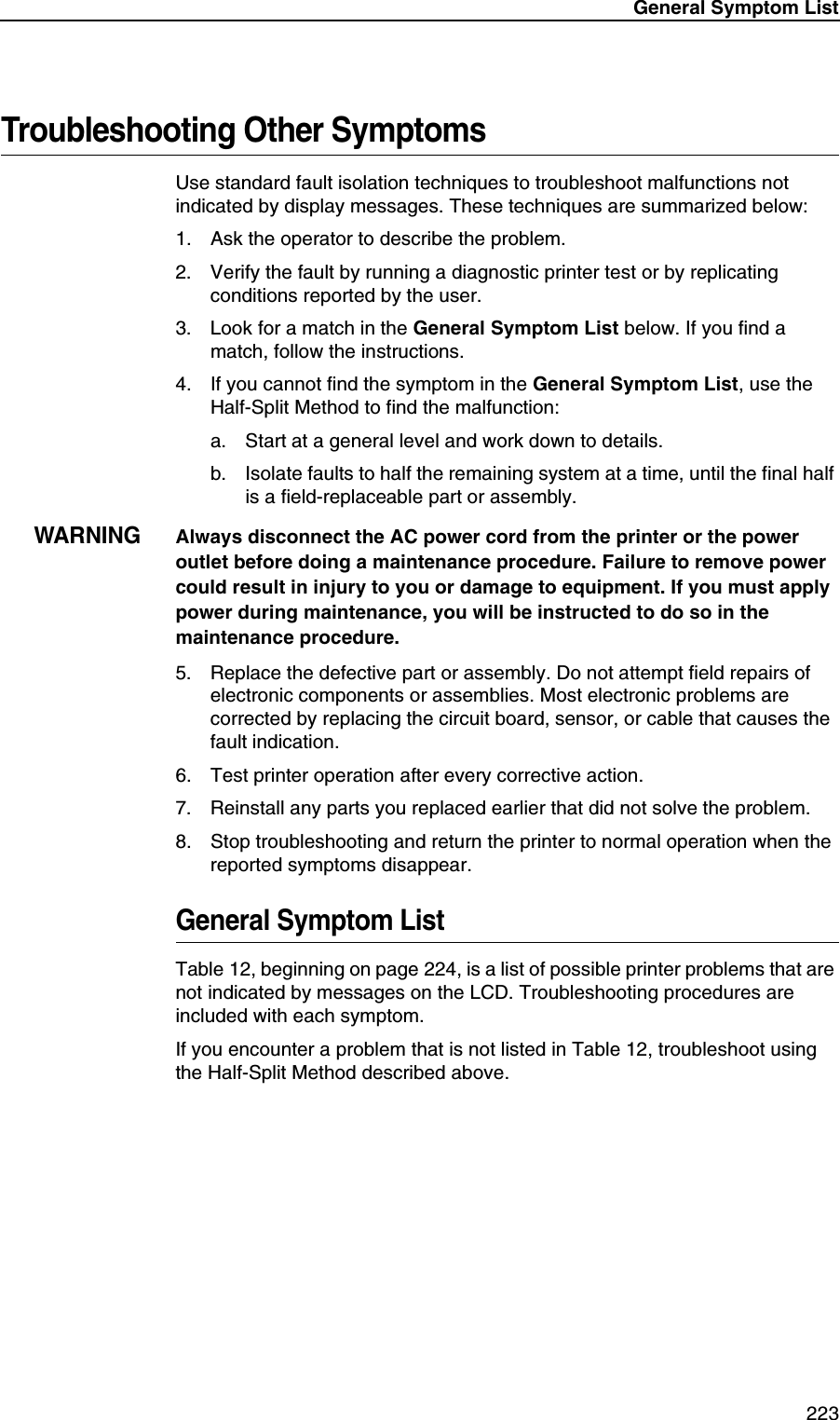
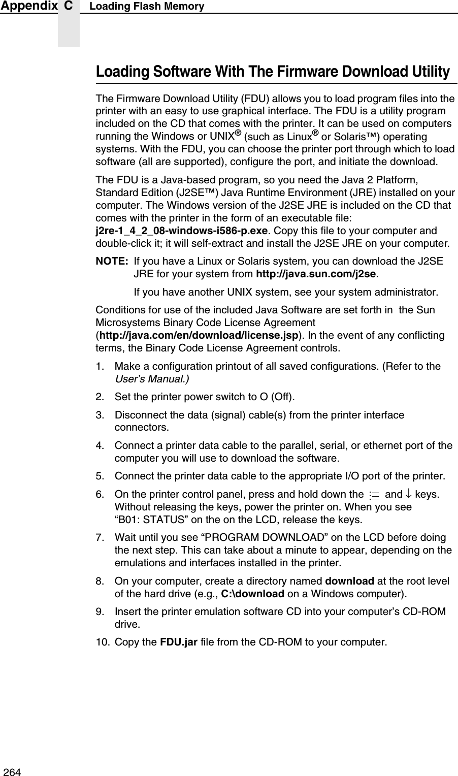
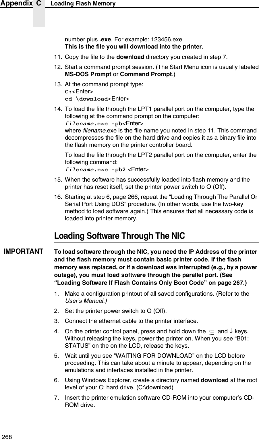
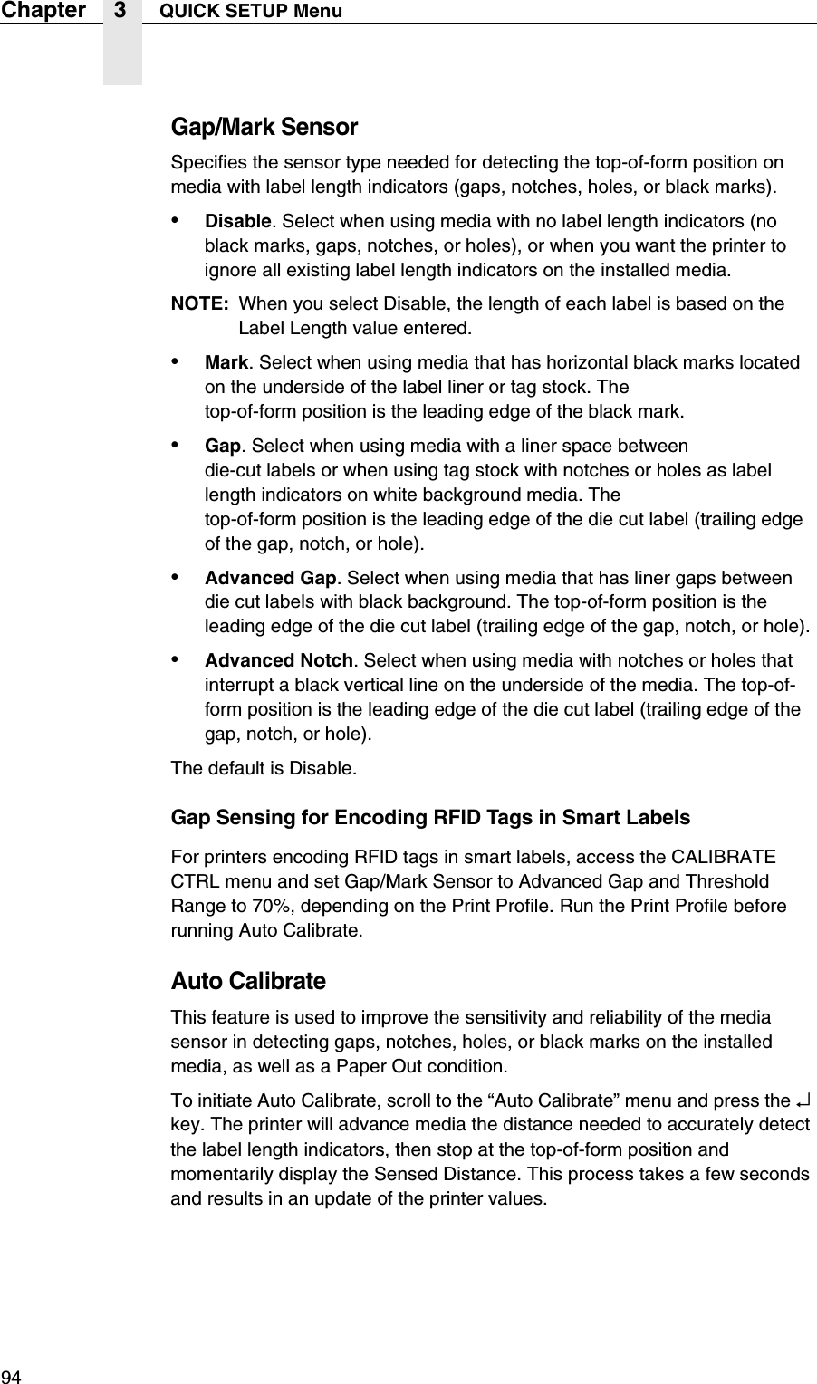
![QUICK SETUP Submenus89NOTE: Many QUICK SETUP submenus are available in other main menus. (Refer to the T5000r User’s Manual.)Changes made in the QUICK SETUP menu are updated in the other main menus, and vice versa.QUICK SETUP SubmenusPrint IntensityThis menu item specifies the level of thermal energy from the printhead to be used for the type of media and ribbon installed.Large numbers imply more heat (thermal energy) to be applied for each dot. This has a significant effect on print quality. The print intensity and speed must match the media and ribbon type to obtain the best possible print quality and barcode grades.The range is –15 through +15:•In Transfer mode, the default is –3.•In Direct Thermal mode, the default is 0.QUICK SETUP(cont. from previous page)SMT: StatusToolset [1]* Toolset [1] to Toolset [4]SMT: Sel ToolsetDisabled* EnabledEPC 1zEPC 2, 3SMT: Select ToolNotes:* = Default.1 Appears only if Toolset [1] is selected underSMT: Sel Toolset.2 Appears only if Toolset [2] is selected underSMT: Sel Toolset.3 Undocumented options are reserved for internal use and future design.UPCA 1zUPCA 2, 3EAN8 1zEAN8 2, 3EAN13 1zEAN13 2, 3UCC128 1zUCC128 2, 3GTIN 1zGTIN 2, 3](https://usermanual.wiki/Printronix/ADMP2PA.Users-Manual-3/User-Guide-595555-Page-14.png)
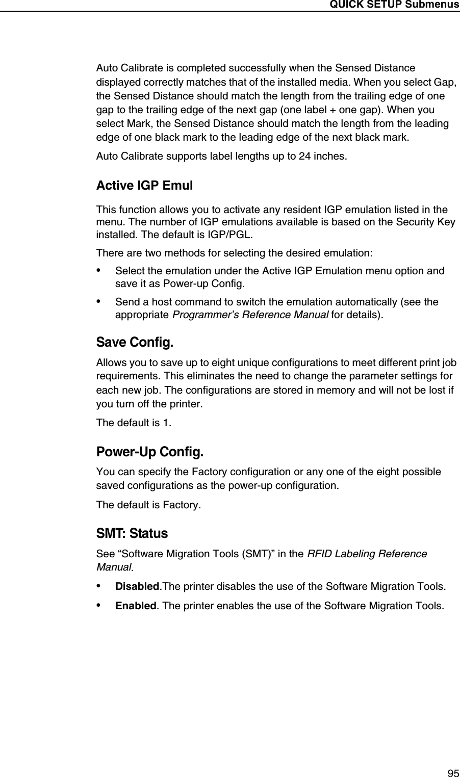
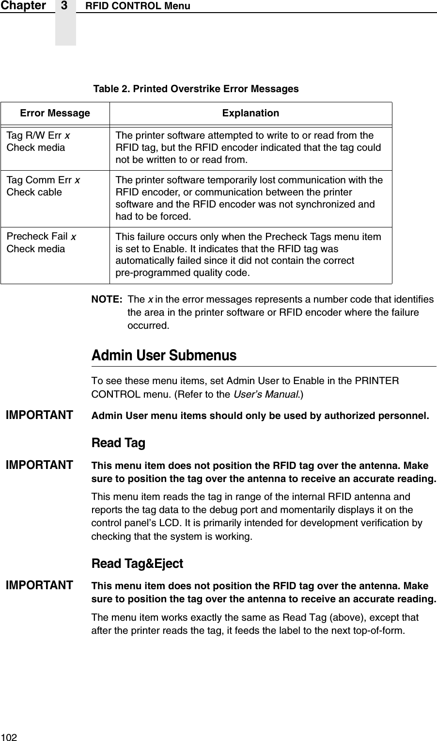
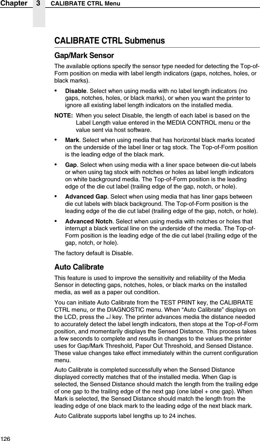
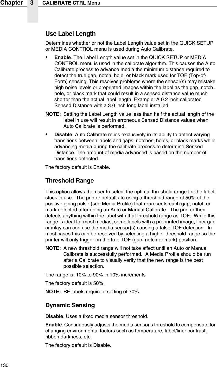
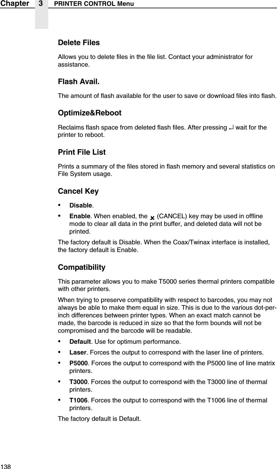
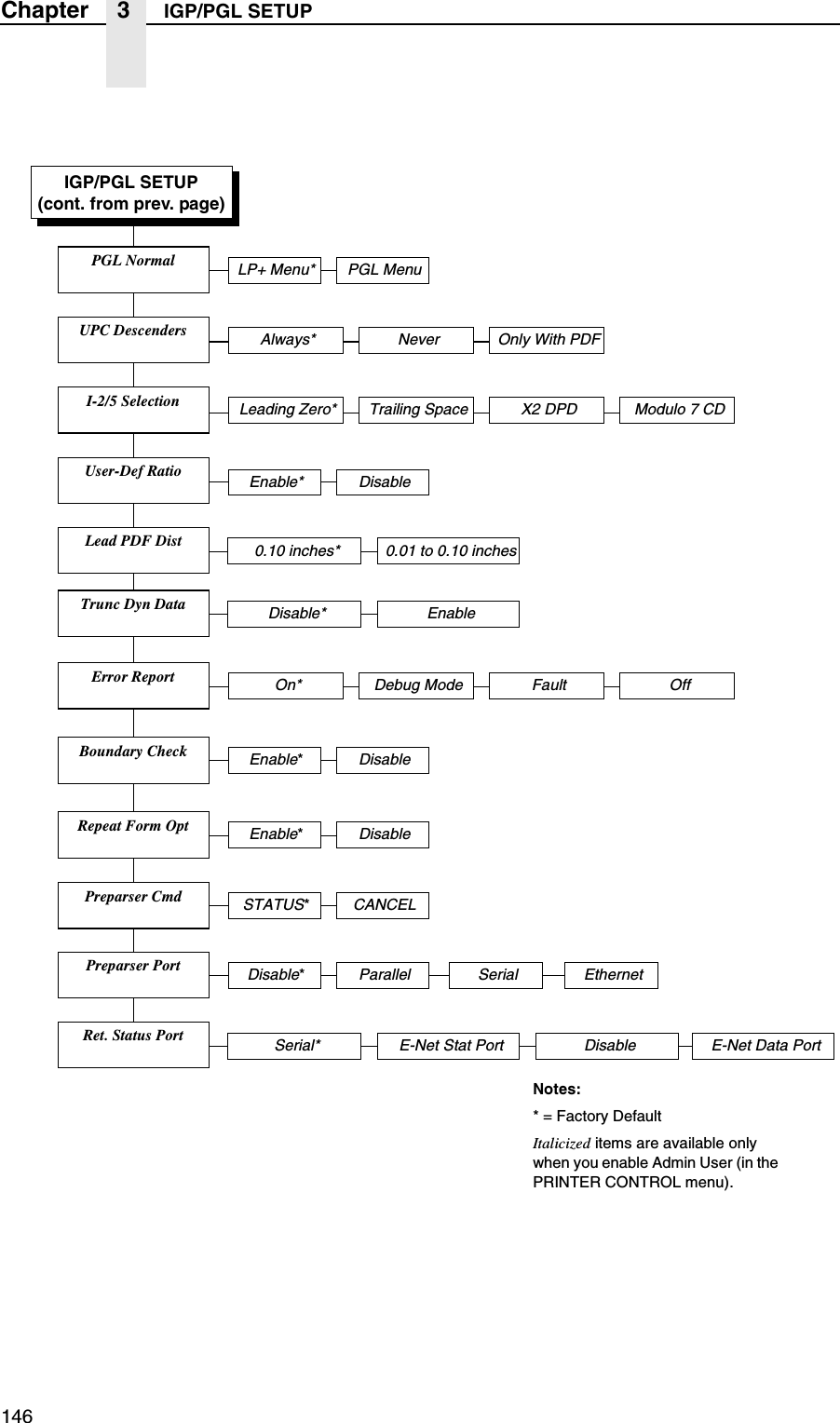
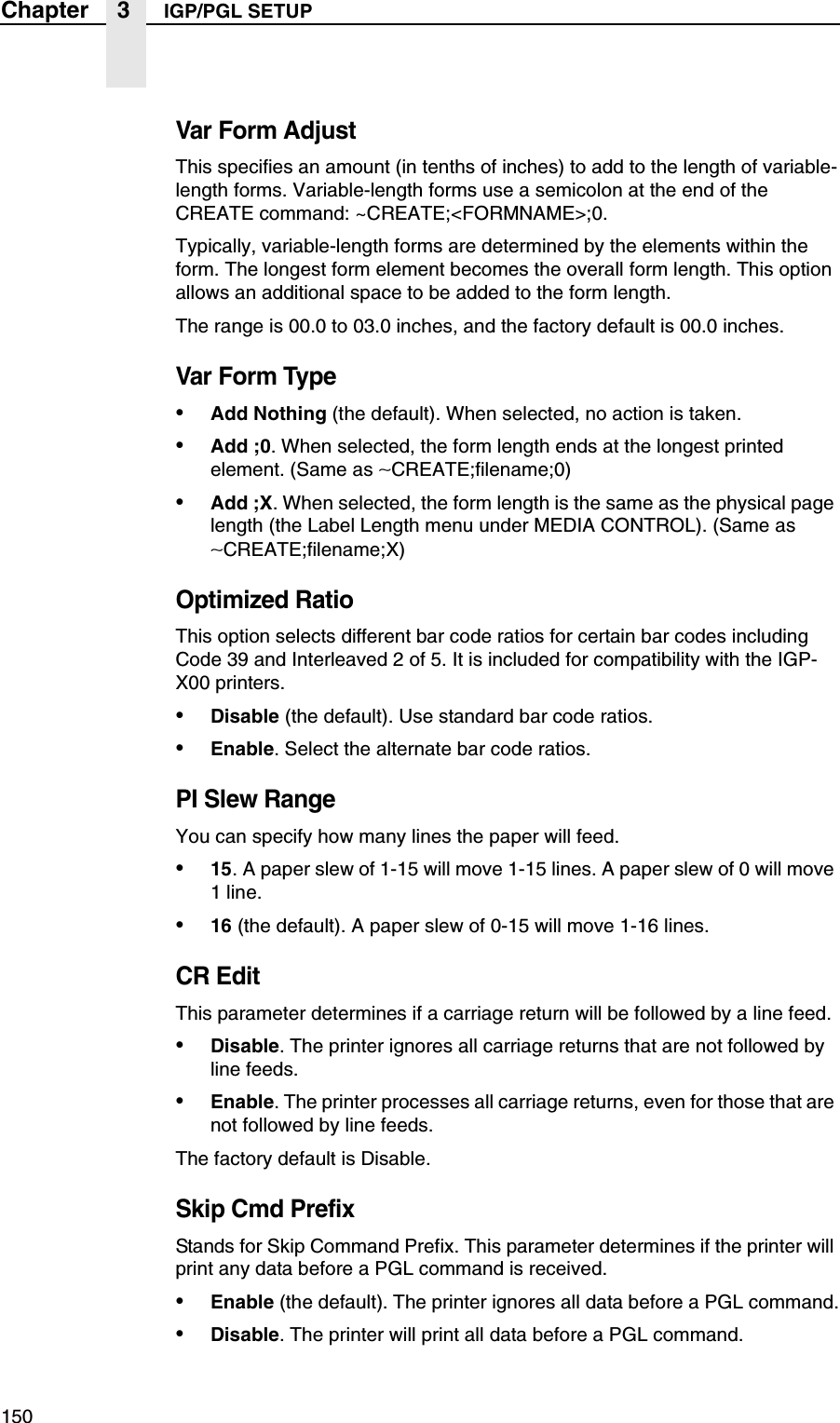
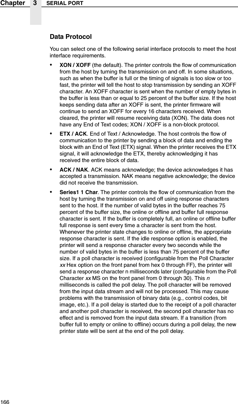
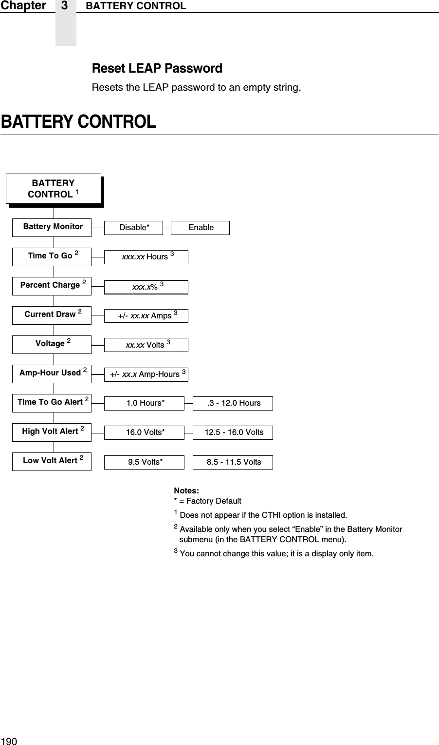
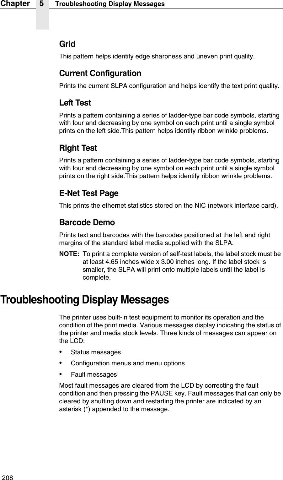
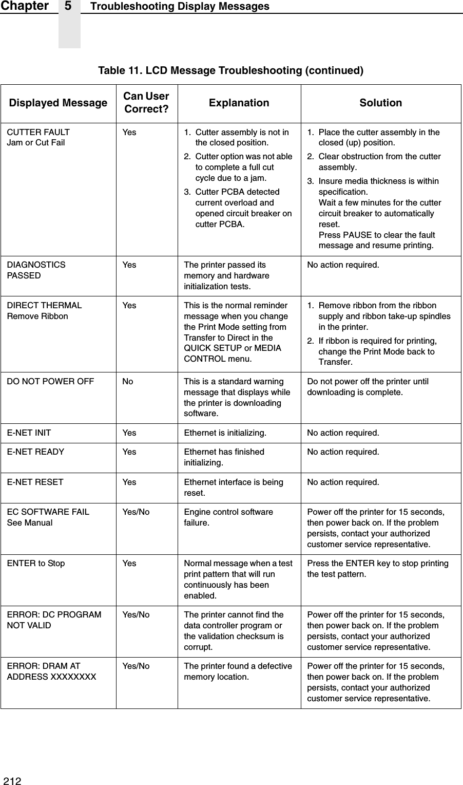
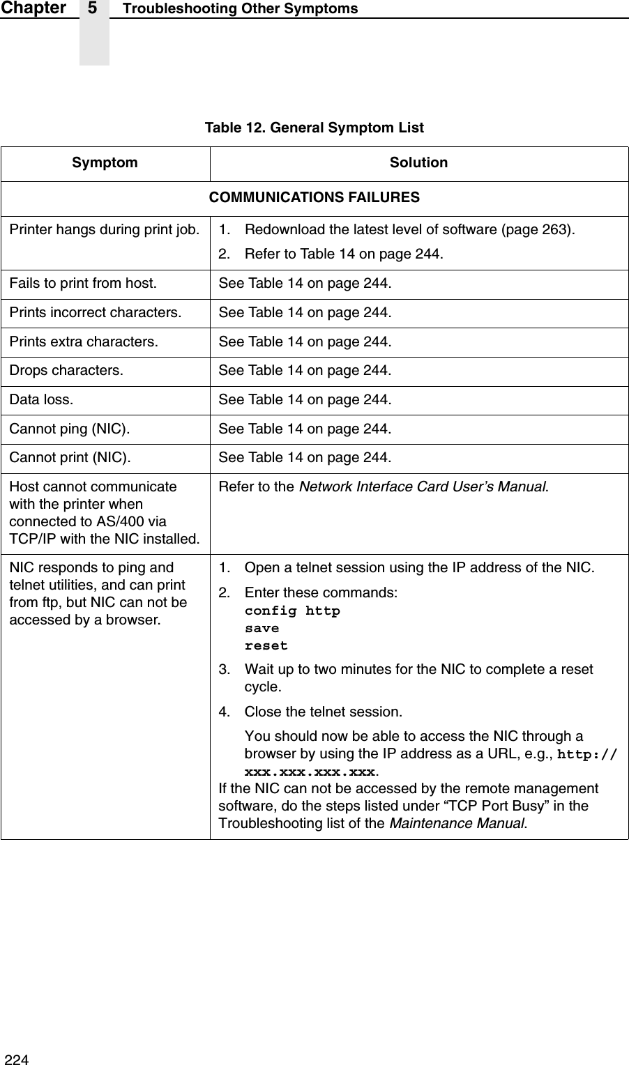
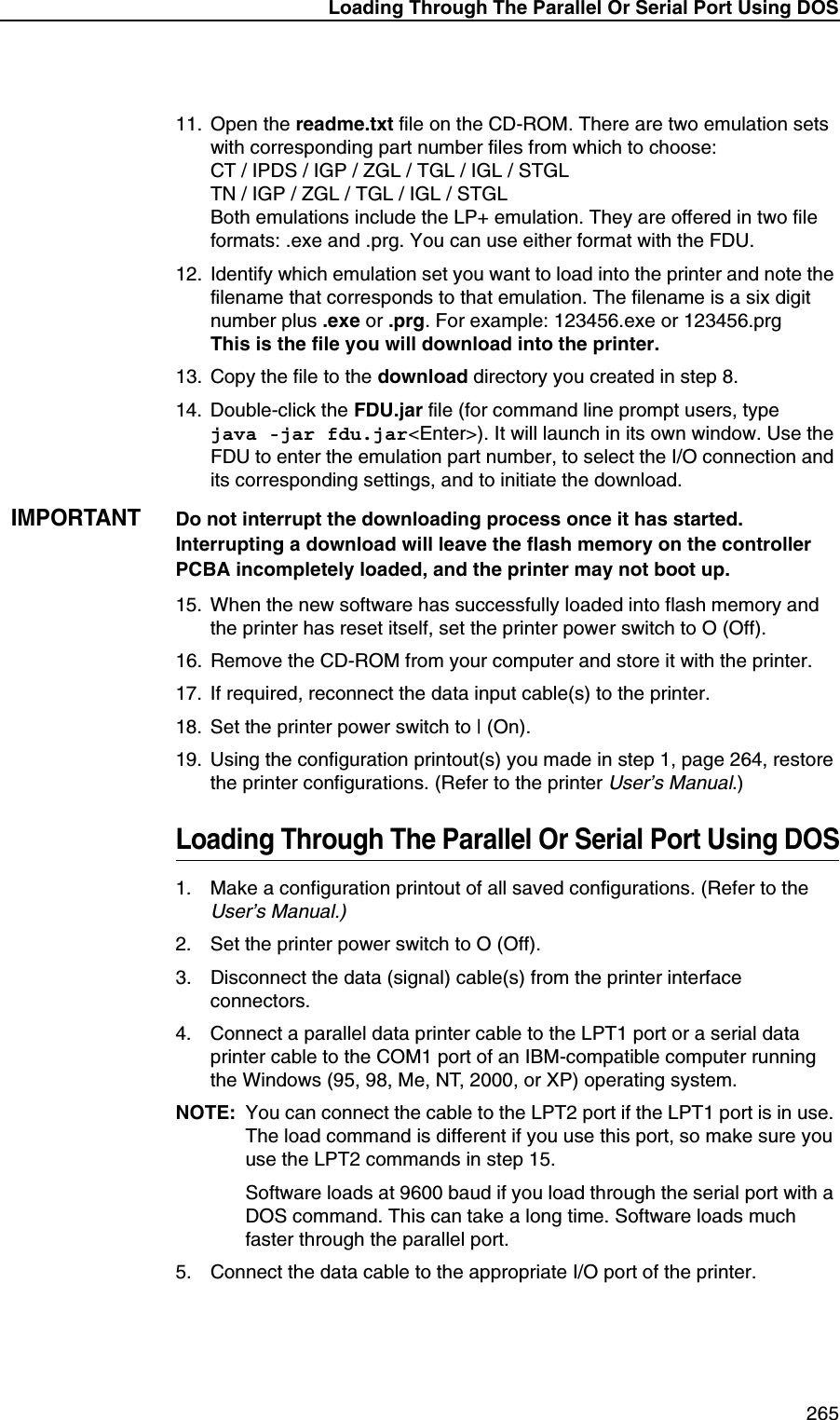
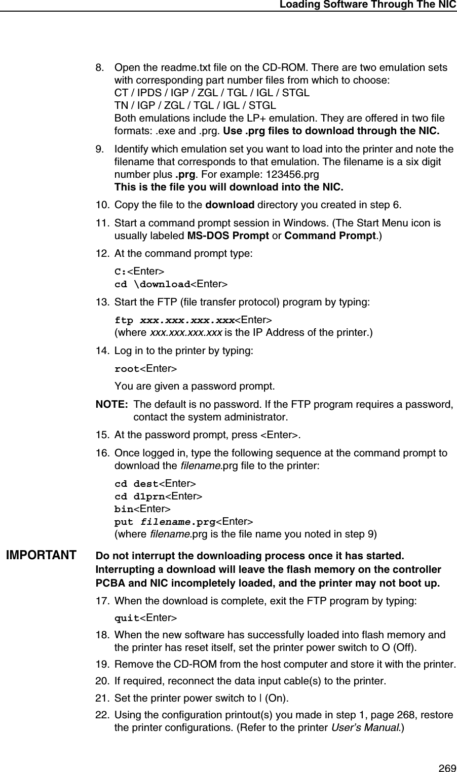
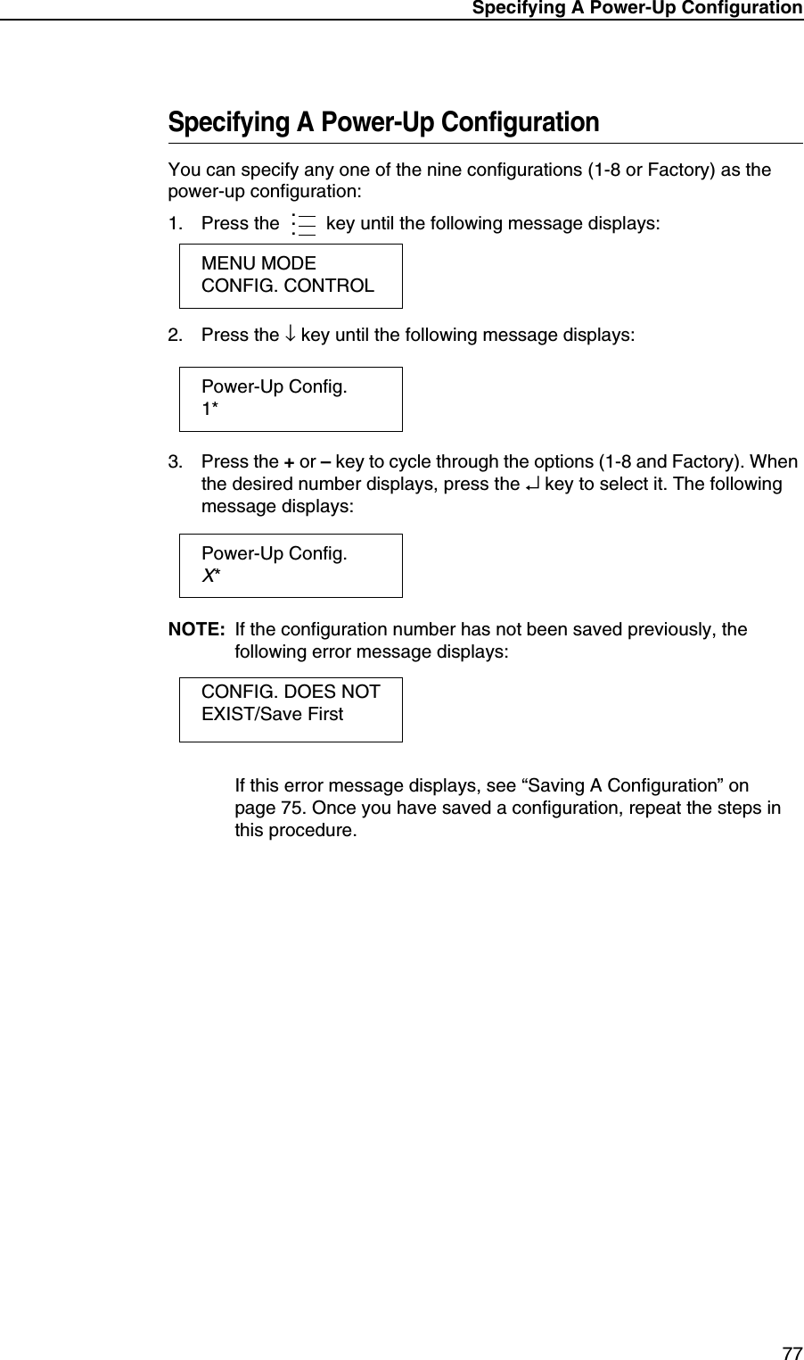
![96Chapter 3 QUICK SETUP MenuSMT: Sel ToolsetSee “Software Migration Tools (SMT)” in the RFID Labeling Reference Manual.•Toolset [1]. SMTs for PGL emulation.•Toolset [2]. SMTs for PPI1 emulation.•Toolset [3] and Toolset [4]. Reserved for internal use and future design.SMT: Select ToolSee “Software Migration Tools (SMT)” in the RFID Labeling Reference Manual.•EPC, GTIN, UPCA, EAN8, EAN13, and UCC128. SMTs displayed if Toolset [1] is selected under SMT: Sel Toolset.•zEPC, zGTIN, zUPCA, zEAN8, zEAN13, and zUCC128. SMTs displayed if Toolset [2] is selected under SMT: Sel Toolset.NOTE: Undocumented options are reserved for internal use and future design.](https://usermanual.wiki/Printronix/ADMP2PA.Users-Manual-3/User-Guide-595555-Page-21.png)