Pro Tech 7208 TYPE 2 User Manual COMPOUND MITER SAW Manuals And Guides 1009985L
User Manual: Pro-Tech 7208 TYPE 2 7208 TYPE 2 PRO-TECH COMPOUND MITER SAW - Manuals and Guides View the owners manual for your PRO-TECH COMPOUND MITER SAW #7208TYPE2. Home:Tool Parts:Pro-Tech Parts:Pro-Tech COMPOUND MITER SAW Manual
Open the PDF directly: View PDF ![]() .
.
Page Count: 28
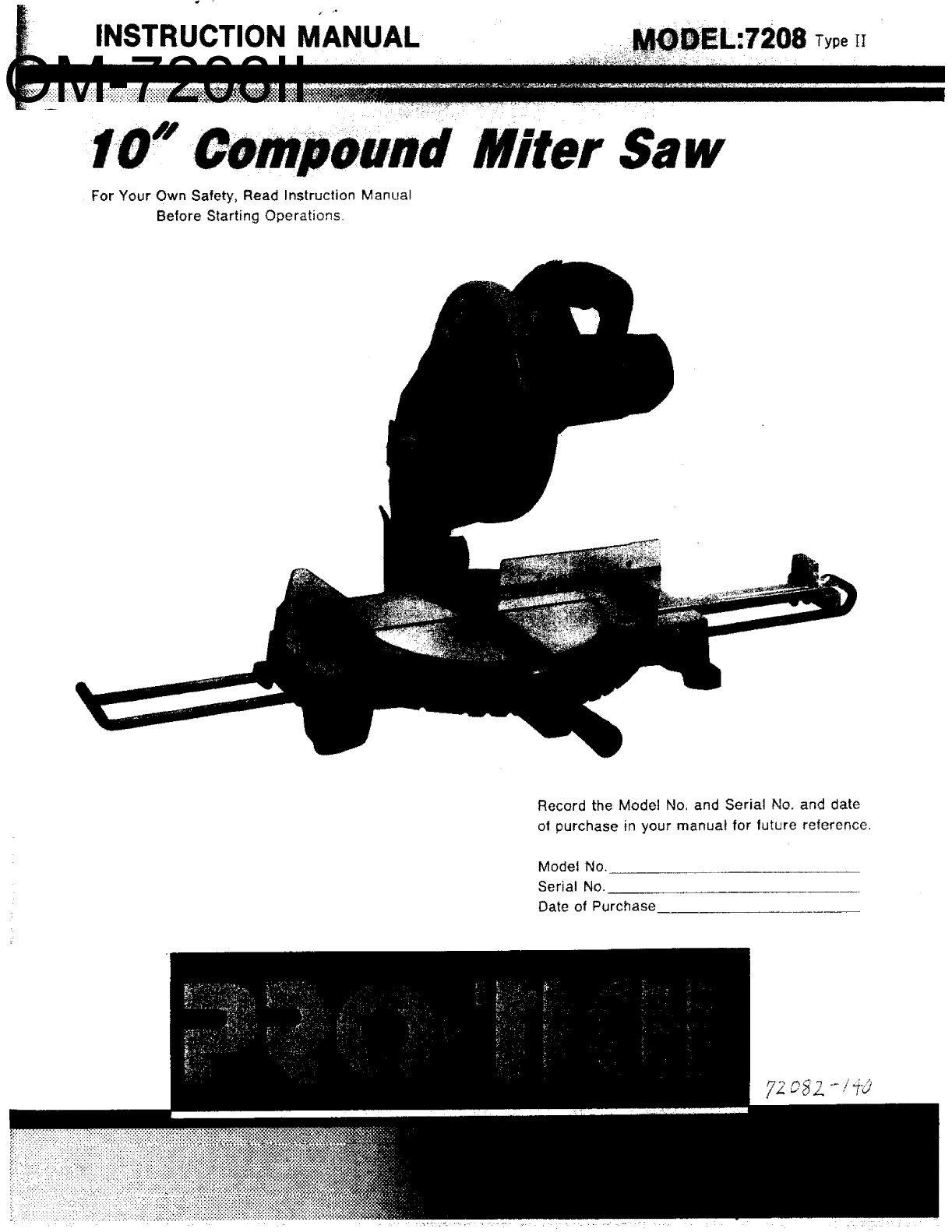
INSTRUCTION MANUAL Type [I
Miter Saw
For Your Own Safety, Read Instruction Manual
Before Starting Operations.
Record the Model No, and Serial No. and date
ot purchase in your manuat for future reference.
Model No.
Serial No.
Date of Purchase
y2 o 8Z --/_-O
Uontents i'"
GENERAL SAFETY RULES ........................ ..i'_,..iii_"'i'i.2 _i_li Arm and Clamp ............ 13
SPECIALSAFETY o Jn, !!i.OMeBlade...................iiii....14
MOTOR _ ____RSAWOPERATION ........... i"" 15
Body:land Hand Position ..................................... 15
... 6
,7
.,=_8
I,,,...L. ...................... :......... g
Mounting the saw ......... i ............................................... 9
Assembling the Lower Blade Guard ........................... 9
Blade Square to Table ............................................... 10
Checking and Adjusting Blade Square ...................... 11
Travel Pivot Adjustment ............................................. 12
Bevel Pivot Adjustment .............................................. 12
Fence Positions ........................................................... 12
Miter/Bevel Cut ..................................... 16
Compound Cut ............................................................ 17
Cutting Bowed Mater al ............................................ 17
Workpiece Support ..................................................... 18
Auxiliary Fence ........................................................... 18
Filler Blocks for Cutting Crown Moldings .................. 19
Vertical Bevel Cutting ................................................. 19
MAINTAINING YOUR MITER SAW ............................. 21
CONTENT PARTS,,_ ..................................................... 22
TROUBLE SHOOTING ................................................. 27
General Safety Rules
1,Know Your Power Tool
Read and understand the owner's manual and
labels affixed to the tool. Learn its application
and limitations as well as the specific potential
hazards peculiar to this tool.
2.Ground all Tools
This tool is DOUBLE INSULATED to give you
added protection. Double insulation does not
take the place of normal safety precautions
when operating this tool. When servicing this
double insulated tool, use only identical parts,
3.Keep Guards in Place
In working order, and in proper adjustment and
alignment.
4.Remove Adjusting Keys and Wrenches
Form a habit of checking to see that keys and
adjusting wrenches are removed from tool
before turning it on.
5,Keep Work Area Clean
Cluttered areas and benches invite accidents.
Floor must not be slippery due to wax or
sawdust.
6.Avoid Dangerous Environment
Don't use power tools in damp or wet locations
or expose them to rain. Keep work area well
lighted. Provide adequate surrounding work
space.
7,Keep Children Away
All visitors should be kept a safe distance from
work area.
8.Make Workshop Child Proof
With padlocks, master switches, or by removing
starter keys.
9.Don't Force Tool
It will do the job better and safer at the rate for
which it was designed.
10.Use Right Tool
Don't force tools or attachment to do a job it
was not designed for.
11,Wear Proper Apparel
Do not wear loose clothing, gloves, neckties or
jewelry (rings, wrist watches) which may get
caught in moving parts. NONSLIP footwear is
recommended, Wear protective hair covering to
contain long hair. Roll long sleeves above the
elbow.
2
12.Use Safety Goggles
Wear safety goggles (must comply with ANStZ
87.1) at all times. Everyday eyeglasses only
have impact resistant lenses, they are NOT
safety glasses, Also, use face or dust mask if
cutting operation is dusty, and ear protectors
(plugs or muffs) during extended periods or
operation.
13,Secure Work
Use clamps or a vise to hold work when
practical. It's safer than using your hands and
frees both hands to operate tool.
14.Don't Overreach
Keep proper footing and balance at all times,
15.Maintain Tools with Care
Keep tools sharp and clean for best and safest
performance. Follow instructions for lubricating
and changing blades, bits, cutters, etc.
16.Disconnect Tools
Before servicing, when changing accessories
such as blades, bits, cutters, etc,
17.Avotd Accidental Starting
Make sure switch is in "OFF" position before
plugging in,
18.Use Recommended Accessories
Consult the owner's manual for recommended
accessories. Follow the instructions that accom-
pany the accessories. The use of improper
accessories may cause hazards.
19.Never Stand on Tool
Serious injury could occur if the tool is tipped or
if the cutting tool is accidentally contacted.
Do not store materials above or near the tool
such that it is necessary to stand on the tool to
reach them,
2O.Check Damaged Parts
Before further use of the tool, aguard or other
part that is damaged should be carefully
checked to ensure that it will operate properly
and perform its intended function, Check for
alignment of moving parts, binding of moving
parts, breakage of parts, mounting, and any
other conditions that may affect its operation. A
guar_ or other part that is damaged should be
properly repaired or replaced.
21,Never Leave Tool Running Unattended
Turn power off, Don't leave tool until it comes to
a complete stop.
Special
BEFORE USING THE SAW:
1. Assembly and alignment.
2. Learn the function and proper use of:
A. The on-off switch.
B. The upper and lower blade guards.
C, The arbor lock and handle latch.
D. The bevel clamp, fence clamps, and miter
lock handle.
3. Read and understand all safety instructions and'
operating procedures throughout the manual.
4. Read the warning label on the miter saw,
WHEN INSTALLING OR MOVING
THE SAW:
1, To avoid injury from unexpected saw movement'.
A. Place the saw on a firm level surface where
there is plenty of room for handling and
properly supporting the workplace.
B. Support the saw so the table is level and the
saw does not rock.
C. Bolt or clamp the saw to its support,
2, Before moving the saw, lock the miter, bevel
and power-head positions. Unplug electric cord.
3, To avoid back injury, get help when you need to
lift the saw more than 10 inches. Hold the tool
close to your body. Bend your knees so you can
lift with your legs, not your back. Lilt by using
the hand-hold areas at the bottom of the base.
Never carry the tool by the cord or power head
handle. Damage to insulation could cause an
electric shock. Damage to wire connections
could cause a fire.
BEFORE EACH USE:
1. Inspect your saw. If any part of this miter saw is
missing, or bent, or has failed in any way, or
any electrical parts don't work properly, turn the
saw off and unplug the saw. Replace damaged,
missing, or failed parts before using the saw
again.
2. Plan Your Work to protect your eyes, hands,
face, and ears.
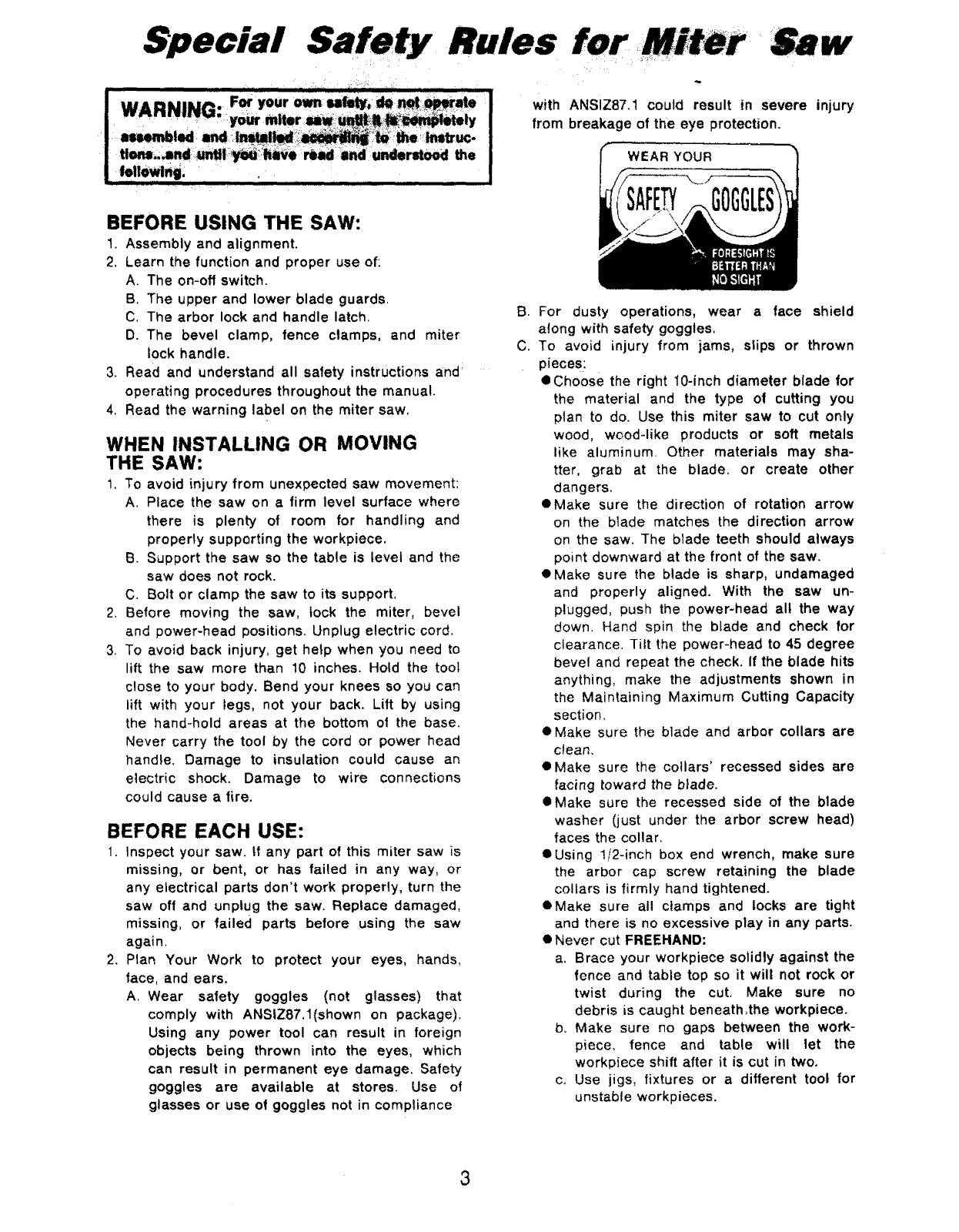
A. Wear safety goggles (not glasses) that
comply with ANStZ87,1(shown on package).
Using any power tool can result in foreign
objects being thrown into the eyes, which
can result in permanent eye damage. Safety
goggles are available at stores. Use of
glasses or use of goggles not in compliance
with ANSiZ87.1 could result in severe injury
from breakage of the eye protection.
WEAR YOUR
B. For dusty operations, wear a face shield
along with safety goggles.
C. To avoid injury from jams, slips or thrown
pieces:
@Choose the right 10-inch diameter blade for
the material and the type of cutting you
ptan to do. Use this miter saw to cut only
wood, wood-like products or soft metals
like aluminum. Other materials may sha-
tter, grab at the blade, or create other
dangers.
eMake sure the direction of rotation arrow
on the blade matches the direction arrow
on the saw. The blade teeth should always
point downward at the front of the saw.
eMake sure the blade is sharp, undamaged
and properly aligned. With the saw un-
plugged, push the power-head all the way
down, Hand spin the blade and check for
clearance. Tilt the power-head to 45 degree
bevel and repeat the check, if the blade hits
anything, make the adjustments shown in
the Maintaining Maximum Cutting Capacity
section,
eMake sure the blade and arbor collars are
clean.
• Make sure the collars' recessed sides are
facing toward the blade.
eMake sure the recessed side of the blade
washer (just under the arbor screw head)
faces the collar.
eUsing 1/2-inch box end wrench, make sure
the arbor cap screw retaining the blade
collars is firmly hand tightened.
eMake sure all clamps and locks are tight
and there is no excessive play in any parts.
• Never cut FREEHAND:
a. Brace your workplace solidly against the
fence and table top so it will not rock or
twist during the cut. Make sure no
debris is caught beneath_the workpiece.
b. Make sure no gaps between the work-
piece, fence and table will let the
workpiece shift after it is cut in two.
co Use jigs, fixtures or a different tool for
unstable workpieces.
3
• Never cut more than one workplace at a time.
• Make sure the cut off piece C_n move
sideways after it's cut off. Otherwise, it could
get wedged against the blade and thrown
violently. .............._ ,_;_
blocks, etc,)for any workpieces large enou-
gh to tip when not held down to the tabte
top.
b. Do not use this saw to cut pieces too small
to let you easily hold the work while you
keep the thumb side of your index (poi-
nter) finger against the outside edge of the
fence.
c. When cutting irregularly shaped work*
pieces, plan your work so it will not slip
and pinch the blade. A piece of motding,
for example, must lie flat or be held by a
fixture or jig that will not let it twist, rock
or slip while being cut.
d. Properly support round material such as
dowel rods, or tubing. They have a
tendency to roll while being cut, causing
the blade to _bite. _ To avoid this, always
use a fixture designed to properly hold
your work piece.
• Make sure there are no nails or foreign
objects in the part of the workpiece to be cut.
• Make sure bystanders are clear of the tool and
workpiece. Keep them clear of the area behind
the saw where debris will be thrown.
• Never turn your miter saw _ON_ before
clearing everything except the workpiece and
related support devices off the table.
D. To avoid risk of hearing damage, wear ear
plugs or muffs during extended periods of
operation.
E, To avoid being suddenly pufled into the blade:
1. Do not wear gloves.
2. Remove all jewelry and loose clothing.
3. Tie back long hair.
4. Rol! long sleeves above the elbow.
G, To avoid an electrical shock, make sure your
fingers do not touch the metal prongs on the
plug when inserting or removing the plug to
or from a live outlet.
H. Never put lubricants on the blade while it's
spinning,
1. To avoid burns or other fire damage, never
use the saw near flammable liquids, vapors or
gases.
J. To avoid injury from unsafe accessories, use
only accessories shown on the recommended
accessories list in this manual.
WHENEVER SAW IS RUNNING:
ii =ii i i =========lllll
I WARNING: Don't allow familiarity (gained trom
Irequent use of your miter saw) to cause a careless
mistake. Always remember that a careless fraction
....#fa second is enough,, t,o cause a severe injury,
1. Before actually cutting with the saw, let it run
for a while. If your saw makes an unfamiliar
noise or if it vibrates excessively, stop immedi-
ately. Turn the saw off. Unplug the saw. Do not
restart until finding and correcting the problem,
2. Never confine the piece being cut off. Never
hold it, clamp it, touch it, or use length stops
against it. It must be free to move sideways. If
confined, it could get wedged against the blade
and thrown violently.
3. Avoid awkward hand positions where a sudden
slip could cause a hand to move into the blade.
4, Let the blade reach ful! speed before cutting.
5. Feed the saw into the workpiece only fast
enough to let the blade cut without bogging
down or binding,
6. Before freeing jammed material, release switch
and unplug the saw. Wait for all moving parts to
stop.
7. After finishing a cut, keep holding the power-
head down, release the switch, and wait for all
moving parts to stop before moving your hands,
f
4
Motor
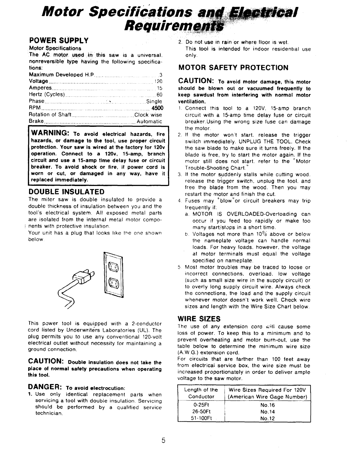
POWER SUPPLY
Motor Specifications
:The AC motor, u_ed _!n this saw is a universal,
nonreversible type having the following specifica-
tions:
Maximum Developed H.P .............................. 3
Voltage ............................................................ 120
Amperes ...................................................... 15
Hertz (Cycles) ................................................ 60
Phase .................................... :.:_...................... Single
RPM ................................................................... 4500
Rotation of Shaft ....................................... Clock wise
Brake ........................................................... Automatic
-- i JJL
WARNING: To avoid electrical hazards, fire
hazards, or damage to the tool, use proper circuit
protection. Your saw is wired at the factory for 120v
operation, Connect to a 120v, 15-amp, branch
circuit and use a 15-amp time delay fuse or circuit
breaker. To avoid shock or fire, if power cord is
worn or cut, or damaged in any way, have it
:replaced immediately.
I,i ii ii ,,,i, ,11
DOUBLE INSULATED
The miter saw is double insulated to provide a
double thickness of insulation between you and the
tool's electrical system. All exposed metal parts
are isolated from the internal metal motor compo-
i nents with protective insulation,
Your unit has a plug that looks like the one shown
below
This power tool is equipped with a 2-conductor
cord listed by Underwriters Laboratories (UL). The
plug permits you to use any conventional 120-volt
electrical outlet without necessity for maintaining a
ground connection.
CAUTION: Double insulation does not take the
place of normal safety precautions when operating
this tool.
DANGER: To avoid electrocution:
1. Use only identical replacement parts when
servicing a tool with double insulation. Servicing
should be performed by a qualified service
technician,
2. Do not use in rain or where floor is wet,
This toot is intended for indoor residential use
only.
MOTOR SAFETY PROTECTION
CAUTION: Toavoid motor damage, this motor
should be blown out or vacuumed frequently to
keep sawdust from interfering with normal motor
ventilation.
1, Connect this tool to a 120V, 15-amp branch
circuit with a 15-amp time delay fuse or circuit
breaker.Using the wrong size fuse can damage
the motor.
2. If the motor won't start, release the trigger
switch immediately. UNPLUG THE TOOL, Check
the saw blade to make sure it turns freely. If the
blade is free, try to start the motor again. If the
motor still does not start, refer to the "MotOr
Trouble-Shooting Chart."
3, It the motor suddenly stalls while cutting wood,
release the trigger switch, unplug the tool, and
free the blade from the wood, Then you may
restart the motor and finish the cut.
4 Fuses may "blow"or circuit breakers may trip
frequently if:
a, MOTOR IS OVERLOADED-Overloading can
occur if you feed too rapidly or make too
many start/stops in a short time,
b. Voltages not more than 10_ above or below
the nameplate voltage can handle normal
loads. For heavy loads, however, the voltage
at motor terminals must equal the voltage
specified on nameplate
5 Most motor troubles may be traced to loose or
incorrect connections, overload, tow voltage
(such as small size wire in the supply circuit) or
to overly long supply circuit wire, Always check
the connections, the load and the supply circuit
whenever motor doesn't work well. Check wire
sizes and length with the Wire Size Chart below,
WIRE SIZES
The use of any extension coro ¢ilt cause some
toss of power. To keep this to a minimum and to
prevent overheating and motor burn-out, use the
table below to determine the minimum wire size
(A.W.G.) extension cord.
For circuits that are farther than 100 feet away
from electrical service box, the wire size must be
increased proportionately in order to deliver ample
voltage to the saw motor.
Length of the Wire Sizes Required For 120V
Conductor (American Wire Gage Number)
0-25Ft No, 16
26-50Ft No,14
51-100Ft No. 12
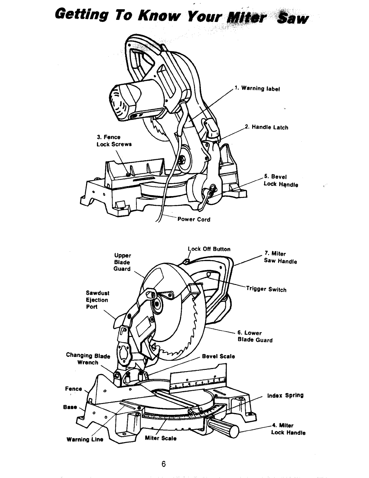
Getting To Know Your
1. Warning label
3. Fence
Lock Screws
Handle Latch
Bevel
LoCk Halndle
Power Cord
Upper
Blade
Guard
Lock Off Button
/7. Miter
Saw Handle
Sawdust
Ejection
Port \
ger Switch
Changing Blade
Wrench Bevel Scale
6. Lower
Blade Guard
Fence o
Warning Line Miter Scale
Index Spring
Miter
Lock Handle
6
Getting To Know
1. Warning label
2. Handle Latch
The miter saw can be locked in the lowered
position for compact storage
3. Fence Lock Screws
The fence has two positions for increased
crosscut capacity. The lock screws secure the
fence to the base. The saw is shipped with the
fence in the rear position.
4. Miter Lock Handle
The miter lock handle securely locks the miter
saw at a desired miter angle, Index points have
been provided at 0°,15°R/L, 22.5°R/L,30°RiL,and
45°RiL.
.
=
The bevel lock handle locks the miter saw at a
desired bevel angle.
Lower Blade Guard
The blade guard helps protect your hands from
the blade in the raised position. To avoid
binding on the workpiece, it retracts as the
blade is lowered.
Miter Saw Handle
The saw handte contains the trigger switch with
a lock-off button, The blade is lowered into the
workpiece by pushing down on the handle. The
saw will return to it's upright position when the
handle is released.
iiiiiiiiiiiiiiii iiiiiiiiiiii i iiiiiiiiiiiiiiii ii i Hill
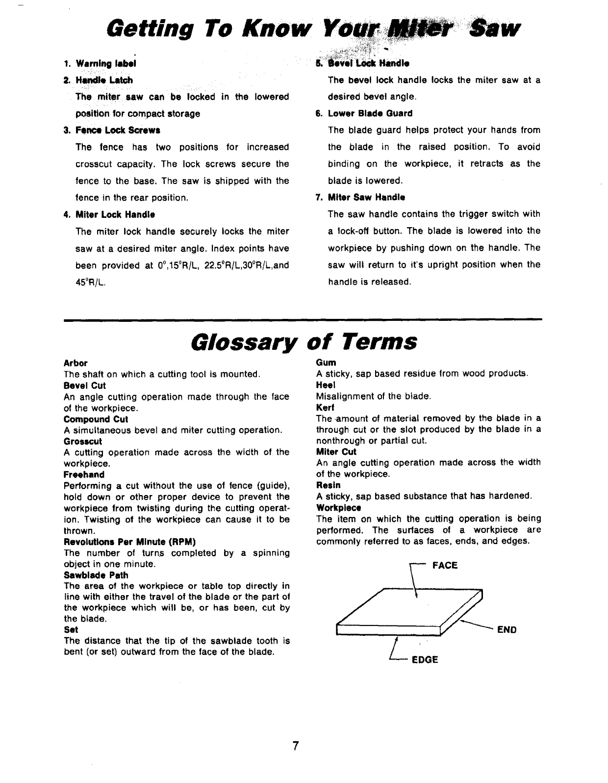
Glossary of
Arbor
The shaft on which acutting tool is mounted,
Bevel Cut
An angle cutting operation made through the face
of the workpiece.
Compound Cut
A simultaneous bevel and miter cutting operation.
Grosscut
A cutting operation made across the width of the
workpiece.
Freehand
Performing a cut without the use of fence (guide),
hold down or other proper device to prevent the
workpiece from twisting during the cutting operat-
ion. Twisting of the worl<piece can cause it to be
thrown.
Revolutions Per Minute (RPM)
The number of turns completed by aspinning
object in one minute.
Sawblade Path
The area of the workpiece or table top directly in
line with either the travel of the blade or the part of
the workpiece which will be, or has been, cut by
the blade.
Set
The distance that the tip of the sawblade tooth is
bent (or set) outward from the face of the blade.
Gum
A sticky, sap based residue from wood products.
Heel
Misalignment of the btade.
Kerr
The.amount of material removed by the blade in a
through cut or the slot produced by the blade in a
nonthrough or partial cut.
Miter Cut
An angle cutting operation made across the width
of the workpiece.
Resin
A sticky, sap based substance that has hardened.
Workplece
The item on which the cutting operation is being
performed. The surfaces of aworkpiece are
commonly referred to as faces, ends, and edges.
EDGE
FACE
END
7
n al
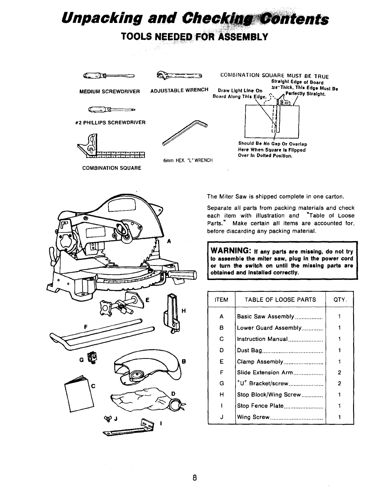
U packing
TOOLS IBLY
MEDIUM SCREWDRIVER
#2 PHILLIPS SCREWDRIVER
COMBINATION SQUARE
ADJUSTABLE WRENCH
6ramHEX,"L"WRENCH
COMBINATION SQUARE MUST GE TRUE
Stratgh! Edge of Board
3/4"'Thtck, This Edge Must Be
Draw Light Line On
°o.,,.,oo0,,,.V0. :i
t.
ShOuld Be No Gap Or Overlap
Here When Square Is Flipped
Over In Doffed Position,
_Perlectly Straight.
A
The Miter Saw is shipped complete in one carton.
Separate all parts from packing materials and check
each item with illustration and =Table of Loose
Parts." Make certain all items are accounted for,
before discarding any packing material.
,,,ll i iiiiiiiiiii i ,,,,,l_lul,iii ii i
l WARNING: If any parts are missing, do not try
I to assemble the miter saw, plug in the power cord
I or turn the switch on until the missing parts are
obtained and installed correctly.
ITEM QTY.
A
B
C
D
E
F
G
H
I
J
TABLE OF LOOSE PARTS
Basic Saw Assembly .................
Lower Guard Assembly .............
Instruction Manual .....................
Dust Bag .....................................
Clamp Assembly
Slide Extension Arm ..................
_U_ Bracket/screw .....................
Stop Block/Wing Screw .............
Stop Fence Plate ........................
Wing Screw ................................
1
1
1
1
I
2
2
1
1
1
8
,q sern u Ey et
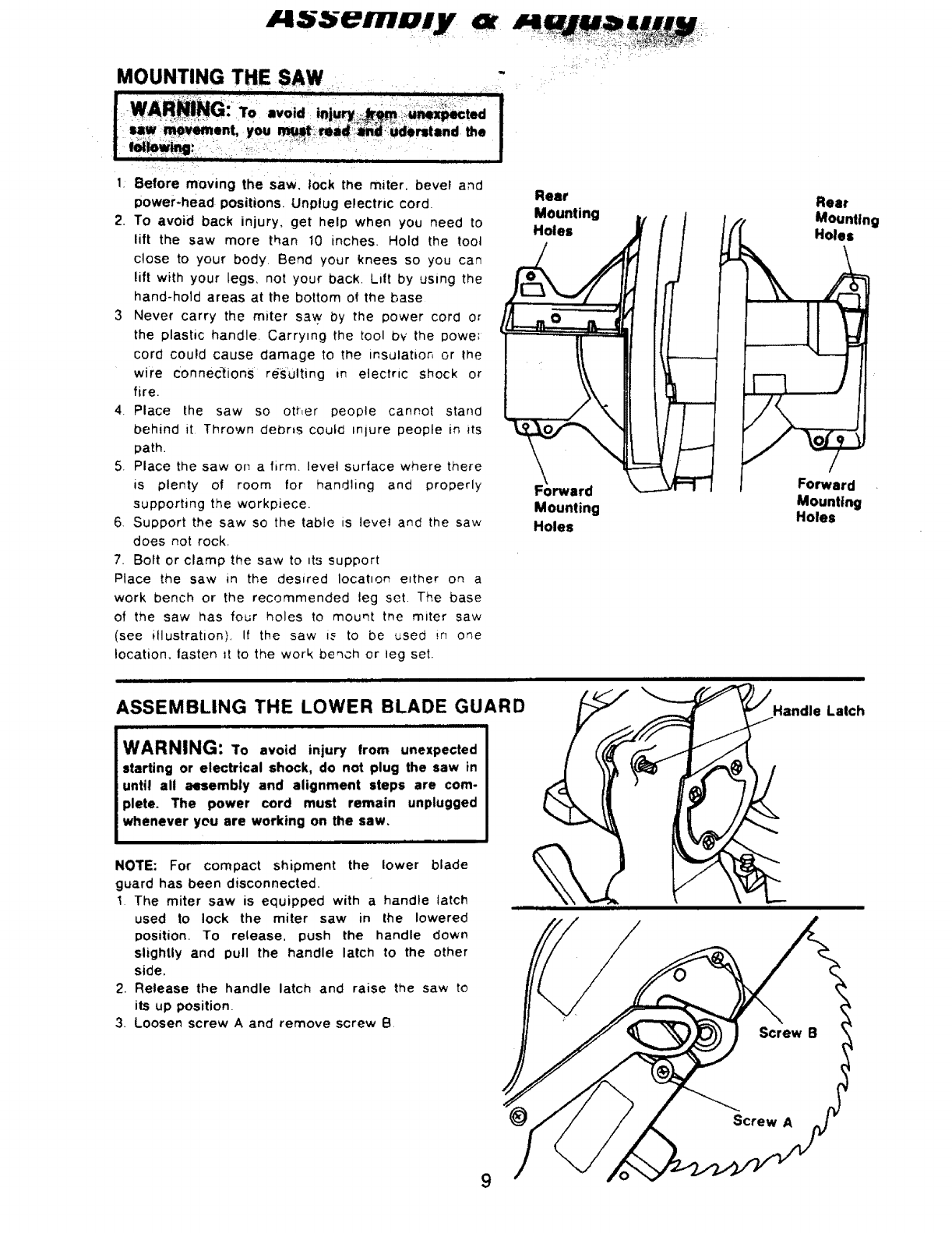
MOUNTING THE SAW
1: Before moving the saw, lock the miter, bevel and Rear
power-head positions. Unplug electric cord. Mounting
2. To avoid back injury, get help when you need to Holes
lift the saw more than 10 inches. Hold the toot
close to your body. Bend your knees so you can
lift with your legs, not your back. Lilt by using the
hand-hold areas at the bottom of the base
3 Never carry the miter s3w by the power cord or
the plastic handle. Carrying the tool bv the powe;
cord could cause damage to the insWatior, or the
wire Connec-tions re-suiting in electric shock or
fire.
4. Place the saw so other people cannot stand
behind it Thrown debris coutcl miure people in its
path.
5_ Place the saw or_ afirm. level surface where there
is plenty of room for handling and properly
supporting the workpiece.
6 Support the saw so the table is levet and the saw
does not rock,
7. Bolt or clamp the saw to _ts support
Place the saw in the desired Iocat=on e_ther on a
work bench or the recommended leg set The base
of the saw has four holes to mount the miter saw
(see illustration) I! the saw is to be used _,n one
location, lasten tt to the work beqch or leg set.
Forward
Mounting
Holes
ASSEMBLING THE LOWER BLADE GUARD
WARNING: To avoid injury from unexpected
starting or electrical shock, do not plug the saw in
until all aGsembly and alignment steps are com-
plete. The power cord must remain unplugged
whenever you are working on the saw,
NOTE: For compact shipment the lower blade
guard has been disconnected.
1 The miter saw is equipped with ahandle latch
used to lock the miter saw in the lowered
position. To release, push the handle down
slightly and pull the handle latch to the other
side.
2. Release the handle latch and raise the saw to
its up position.
3. Loosen screw A and remove screw 8
Rear
Mounting
Holes
Forward
Mounting
Holes
Handle Latch
9
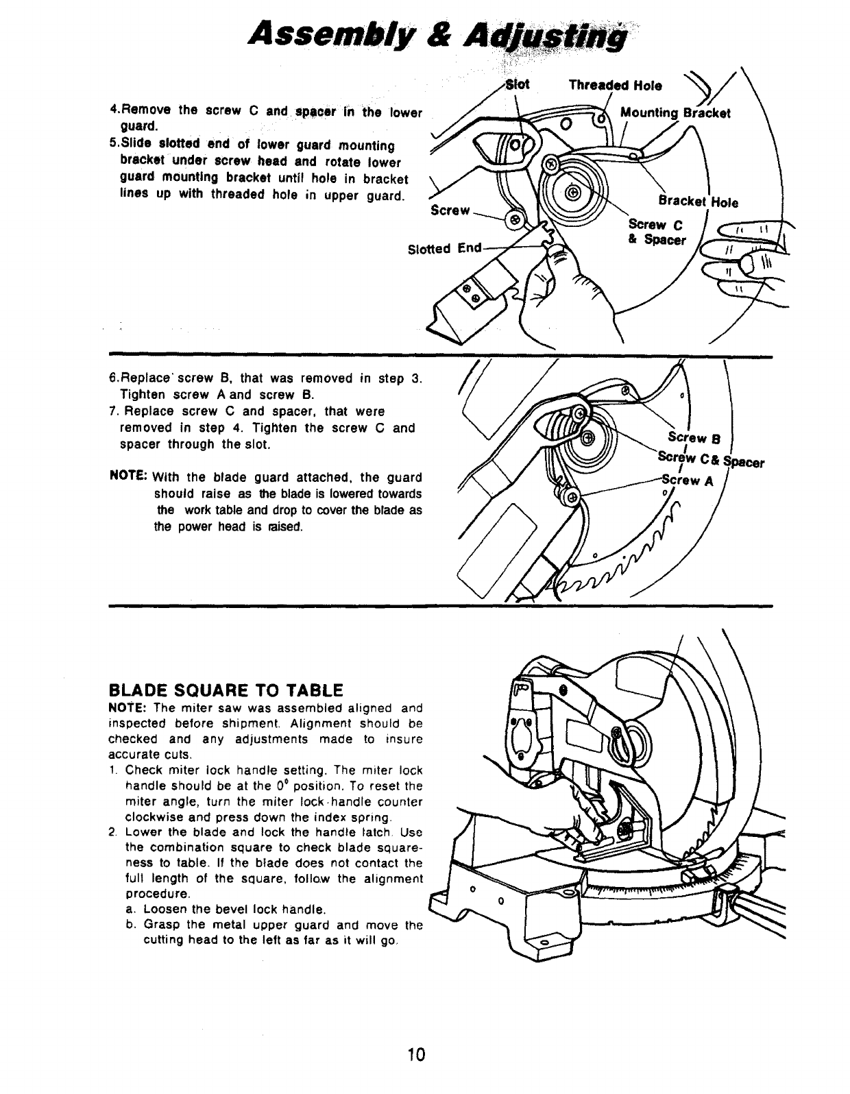
4.Remove the screw C and spacer in the lower
guard.
5,Slide slotted end of lower guard mounting
bracket under screw head and rotate lower
guard mounting bracket until hole in bracket
lines up with threaded hole ;n upper guard.
Threaded Hole
Mounting Bracket
Slotted & Spacer
6.Replace' screw B, that was removed in step 3.
Tighten screw A and screw B.
7. Replace screw C and spacer, that were
removed in step 4. Tighten the screw C and
spacer through the slot.
NOTE: With the blade guard attached, the guard
should raise as the blade is lowered towards
the work table and drop to cover the blade as
the power head is raised.
\
Screw B
iiiiiiiiiiiiiiii ii iii iiiiiii -
BLADE SQUARE TO TABLE
NOTE: The miter saw was assembled aligned and
inspected before shipment. Alignment should be
checked and any adjustments made to insure
accurate cuts,
!. Check miter lock handle setting. The miter lock
handle should be at the 0° position, To reset the
miter angle, turn the miter lock-handle counter
clockwise and press down the index spring.
2 Lower the blade and lock the handle latch, Use
the combination square to check blade square-
ness to table, If the blade does not contact the
full length of the square, follow the alignment
procedure.
a, Loosen the bevel lock handle.
b. Grasp the metal upper guard and move the
cutting head to the left as far as it will go,
10
A;
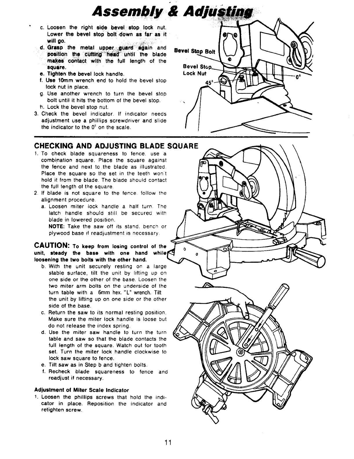
c, Loosen the right side bevel stop lock nut.
:, ,.: : : .....
Lower the bevel stop bolt: .down as faras it
will go, i ....... :i:_il j
d. Grasp the metal upper,,i_:g_rd !:Im_in and
:position the i_i_:_i:_:h_i'iUhtilthe blade
co,tactw th lengtho, the
square,
e. Tighten the bevel lock handle.
f, Use 10ram wrench end to hold the bevel stop
tock nut in place.
g. Use another wrench to turn the bevel stoD
bolt until it hits the bottom of the bevel stop.
h, Lock the bevel stop nut.
3, Check the bevel indicator. If indicator needs
adjustment use a phillips screwdriver and slide
the indicator to the 00 on the scale.
Bevel Sto
Bevel
Lock Nut
,,,,,,,,,,,,,,,,,,,,,,,,,,,,,,,,,,,,,,,,,,,,,,,, ,,,,,,,,,,,, , illlllll L Jill1
CHECKING AND ADJUSTING BLADE SQUARE
I, To check blade squareness to tence_ use a
combination square, Place the square against
the fence and next to the blade as illustrated,
Place the square so the set in the teeth won't
hold it from the blade. The blade should contact
the full length of the square=
2If blade is not square to the fence, follow the
alignment procedure,
a, Loosen miter tock handle a half turn. ]-he
latch handle should still be secured witt7
blade in lowered position.
NOTE: Take the saw oft its stand, bench or
plywood base if readjustment is necessary.
CAUTION: To keep from losing control of the
unit, steady the base with one hand while
loosening the two bolts with the other hand,
b, With tt_e unit securely resting on a large
stable surface, tilt the unit by lifting up on
one side or the other of the base. Loosen the
two miter arm bolts on the underside of the
turn table with a 6rnm hex. "L" wrench. Tilt
the unit by lifting up on one side or the other
side of the base.
c, Return the saw to its normal resting position.
Make sure the miter lock handle is loose but
do not release the index spring.
d. Use the miter saw handle to turn the turn
table and saw so that the blade contacts the
full length of the square. Watch out for tooth
set. Turn the miter lock handle clockwise to
lock saw square to fence,
e. Tilt saw as in Step b and tighten bolts,
f. Recheck blade squareness to fence and
readjust it necessary.
Adjustment of Miter Scale Indicator
1Loosen the phillips screws that hold the indi-
cator in place, Reposition the indicator and
retighten screw,
11
Ass,
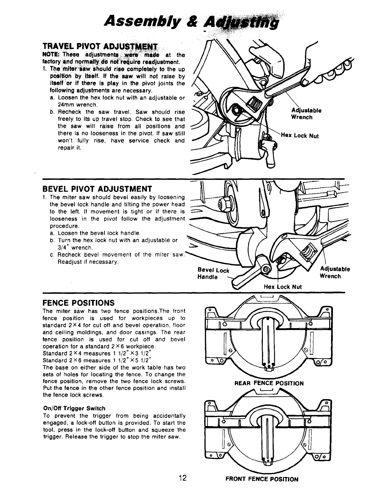
TRAVEL PIVOT ADJU : T
.OTE:These at the
factory _:_andn_rmlt_ild_ i_ot_i'_u|i'e r"djustment.
1. T_imiter_';a_ Shouidrise completely to the up
pos!_On by itself, If the _saw will not raise by
itself or if there is play in the pivot joints the
following adjustments are necessary.
a. Loosen the hex lock nut with an adjustable or
24turn wrench.
b. Recheck the saw travel. Saw should rise
freely to its up travel stop. Check to see that
the saw will raise from all positions and
there is no looseness in the pivot. If saw still
won't fully rise, have service check and
repair it.
Adjustable
Wrench
Lock Nut
BEVEL PIVOT ADJUSTMENT
1. The miter saw should bevel easily by loosening
the bevel lock handle and tilting the power head
to the left. If movement is tight or if there is
looseness in the pivot follow the adjustment
procedure.
a. Loosen the bevel lock handle.
b. Turn the hex lock nut with an adjustable or
3/4" wrench.
c. Recheck bevel movement of the miter
Readjust if necessary.
Bevel Lock
Handle
FENCE POSITIONS
The miter saw has two fence positions.The front
fence position is used for workpieces up to
standard 2 ×4 for cut off and bevel operation, floor
and ceiling moldings, and door casings. The rear
fence position is used for cut off and bevel
operation for astandard 2 ×6 workpiece.
Standard 2×4 measures 1 1/2 _ x3 1/2 _
Standard 2;<6 measures 1 I/2" x5 1/2"
The base on either side of the work table has two
sets of holes for locating the fence. To change the
fence position, remove the two fence lock screws.
Put the fence in the other fence position and install
the fence lock screws.
REAR FENCE POSITION
On/Off Trigger Switch
To prevent the trigger from being accidentally
engaged, a lock-off button is provided. To start the
tool, press in the lock-off button and squeeze the
trigger. Release the trigger to stop the miter saw.
Adjustable
Wrench
12 FRONT FENCE POSITION
Assembly
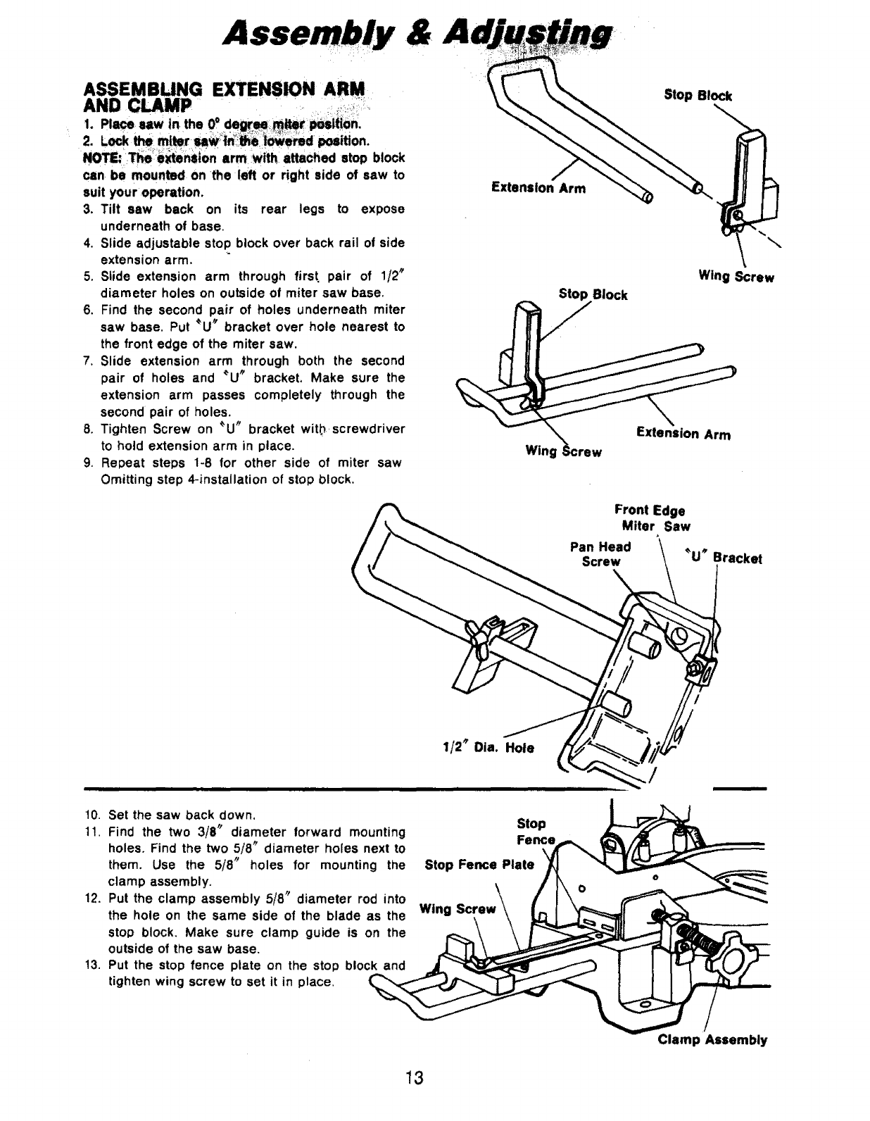
ASSEMBLINGEXTENSIONARM
AND CLAMP o:
2. Lock the m!_r_W_:i_ei_emd _tion.
NOTE: T_ :_te_ion arm Withl attached stop block
can be mounted on the left or right side of saw to
suit your operation.
3. Tilt saw back on its rear legs to expose
underneath of base.
4. Slide adjustable stop block over back rail of side
extension arm,
5. Stide extension arm through first, pair of 1/2"
diameter holes on outside of miter saw base,
6, Find the second pair of holes underneath miter
saw base, Put _U_ bracket over hole nearest to
the front edge of the miter saw.
7. Slide extension arm through both the second
pair of holes and _U" bracket, Make sure the
extension arm passes completely through the
second pair of holes,
8. Tighten Screw on _U" bracket with screwdriver
to hold extension arm in place.
9. Repeat steps 1-8 for other side of miter saw
Omitting step 4-installation of stop block.
Stop Block
Extenslon Arm
Stop Block
\
Wing Screw
Wing _;crew
Extension Arm
Front Edge
Miter Saw
Pan Head
Screw _U_ Bracket
t0.
11.
12.
13.
1/2 _Dia. Hole
Set the saw back down,
Find the two 3/8" diameter forward mounting
holes. Find the two 5/8 _diameter holes next to
them. Use the 5/8" holes for mounting the
clamp assembly.
Put the clamp assembly 5/8 _diameter rod into
the hole on the same side of the blade as the
stop block. Make sure clamp guide is on the
outside of the saw base,
Put the stop fence plate on the stop block and
tighten wing screw to set it in place.
Stop
Fence
Stop Fence Plate
Wing Screw
Clamp Assembly
13
&A
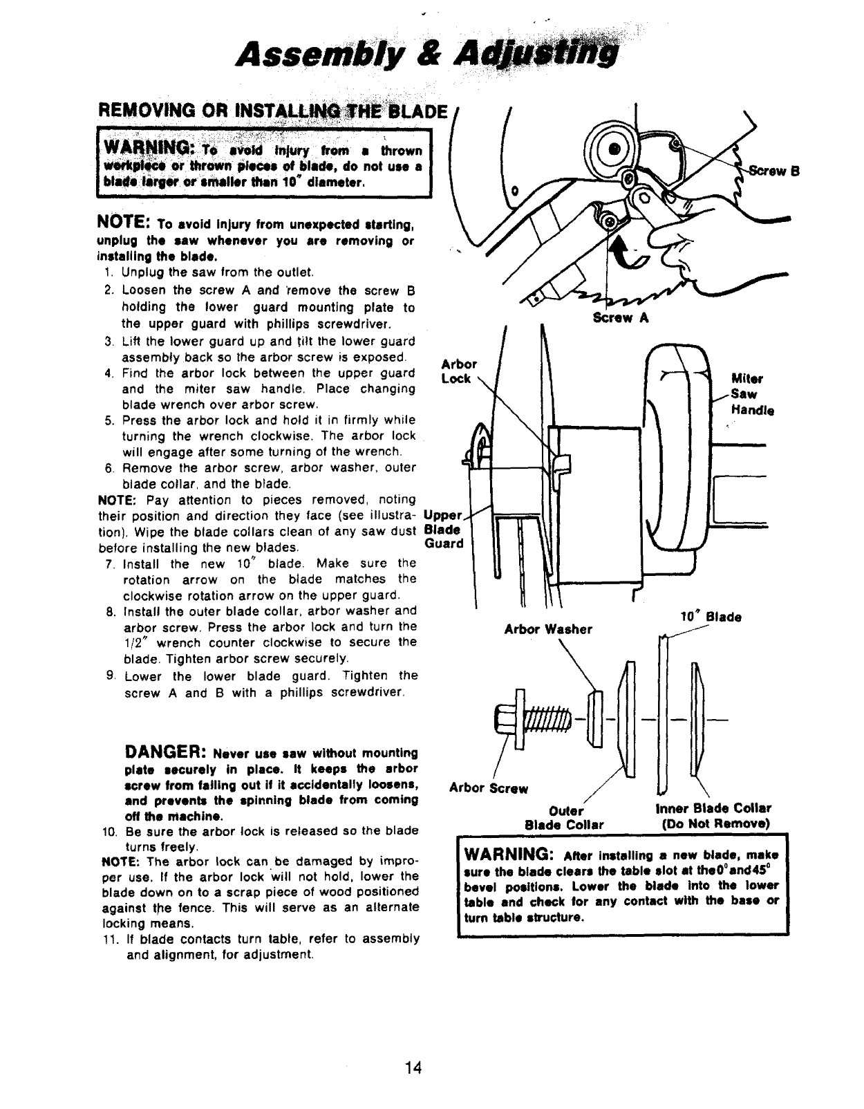
REMOVING
NUll:: To avoid Injury from unexpected starting,
unplug the saw whenever you are removing or
installing the blade.
1. Unplug the saw from the outlet.
2. Loosen the screw A and 'remove the screw B
holding the lower guard mounting plate to
the upper guard with phillips screwdriver.
3. Lift the lower guard up and tilt the lower guard
assembly back so the arbor screw is exposed.
4. Find the arbor lock between the upper guard
and the miter saw handle. Place changing
blade wrench over arbor screw.
5. Press the arbor lock and hold it in firmly while
turning the wrench clockwise. The arbor lock
will engage after some turning of the wrench.
6. Remove the arbor screw, arbor washer, outer
blade collar, and the blade.
NOTE: Pay attention to pieces removed, noting
their position and direction they face (see illustra-
tion). Wipe the blade collars clean of any saw dust
before installing the new blades.
7. install the new 10" blade. Make sure the
rotation arrow on the btade matches the
clockwise rotation arrow on the upper guard.
8. Instal! the outer blade collar, arbor washer and
arbor screw. Press the arbor lock and turn the
1/2" wrench counter clockwise to secure the
blade. Tighten arbor screw securely.
9. Lower the lower blade guard. Tighten the
screw A and B with a phillips screwdriver.
DANGER: Never use saw without mounting
plate securely in place. It keeps the arbor
screw from falling out if it accidentally loosens,
and prevents the spinning blade from coming
off the machine.
10. Be sure the arbor lock is reteased so the blade
turns freely.
NOTE: The arbor lock can be damaged by impro-
per use. If the arbor lock will not hold, lower the
blade down on to a scrap piece of wood positioned
against the fence. This will serve as an alternate
locking means.
11. If blade contacts turn table, refer to assembly
and alignment, for adjustment.
Screw A
Miter
Handle
U
Blade
Guard
Arbor Washer 10 _Blade
/
Arbor Screw \
Ouler Inner Blade Collar
Blade Collar (Do Not Remove)
,, ,, ,,
WARNING: Alter installing a new blade, make
sure the blade clears the table slot at the0°and45 _
bevel positions. Lower the blade into the lower
table and check Ior any contact with the base or
turn table stru_ure.
B
14
Miter
1. Inspect your saw. Replace dama_ missing or
failed paris before using th9 llw,:_ _::
2. Wear safety __IU_)that comply
3. For: dusty operations, wear aface shield along
with safety goggles.
4. To avoid injury from jams, slips or thrown
pieces:
a. Choose the right lO-inch diameter blade for
the material and the type of cutting you plan
to do. Use this miter saw to cut only wood,
woodlike products or soft metals like alumi-
num. Other materials may shatter, grab at
the blade or create other dangers.
b. Make surethe direction of rotation arrow on
the blade matches the d_rection arrow on the
saw_ The teeth of the blade should always
point downward at the front of the saw.
c. Make sure the blade is sharp, undamaged
and properly aligned.
d. Make sure the blade and arbor collars are
clean.
e. Make sure the collars' recessed sides are
facing toward the blade.
f. Make sure the recessed side of the blade
washer (just under the arbor screw head)
faces the collar.
gUsing a 1/2" box end wrench, make sure the
arbor screw retaining the blade collars is
firmly hand tightened.
h. Make sure alt clamps and locks are tight and
there is no excessive play in any parts.
5. Never cut more than one workpiece at a time.
6. Make sure the cut off piece can move sideways
Saw
after it's cut off. Otherwise, it could get
wedged against the blade and thrown violent-
ly.
7. Never cut FREEHAND:
a. Brace your workpiece solidly against the
fence and table top so it will not rock or
twist during the cut. Make sure there is no
debris caught beneath the workpiece.
b. Make sure no gaps between the workpiece,
fence and table will cause shifting after the
workpiece is cut in two.
e. Use jigs, fixtures or a different tool for
unstable workpieces.
8. Use extra caution with large, very small or
awkward workpieces:
a. Use extra supports (tables, saw horses,
blocks, etc.) for any workpieces large
enough to tip when not held down to the
table top.
b. Do not use this saw to cut pieces too small
to let you easily hold the work while you
keep the thumb side of your index (pointer)
finger against the cutside edge of the fence.
c, When cutting irregularly shaped workpieces,
plan your work so it will not slip and pinch
the blade. A piece of molding, for example,
must lie flat or be held by a fixture or jig
that will not let it twist, rock or slip while
being cut.
d. Properly support round material such as
dowel rods, or tubing. They have atende-
ncy to roll while being cut, causing the
blade to _bite." To avoid this, use a fixture
designed to properly hold your workpiece,
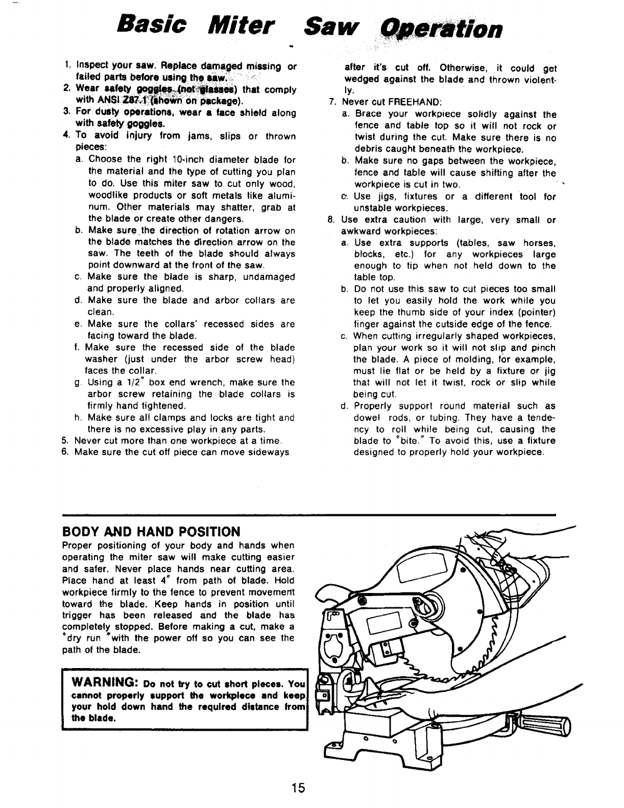
BODY AND HAND POSITION
Proper positioning of your body and hands when
operating the miter saw will make cutting easier
and safer. Never place hands near cutting area.
Place hand at least 4" from path of blade. Hold
workpiece firmly to the fence to prevent movement
toward the blade. Keep hands in position until
trigger has been released and the blade has
completely stopped. Before making a cut, make a
_dry run _with the power off so you can see the
path of the blade.
WARNING: Do not try to cut short pieces. You I
cannot properly support the workplace and keepl
your hold down hand the required distance from_
the blade. I
,....... I
15
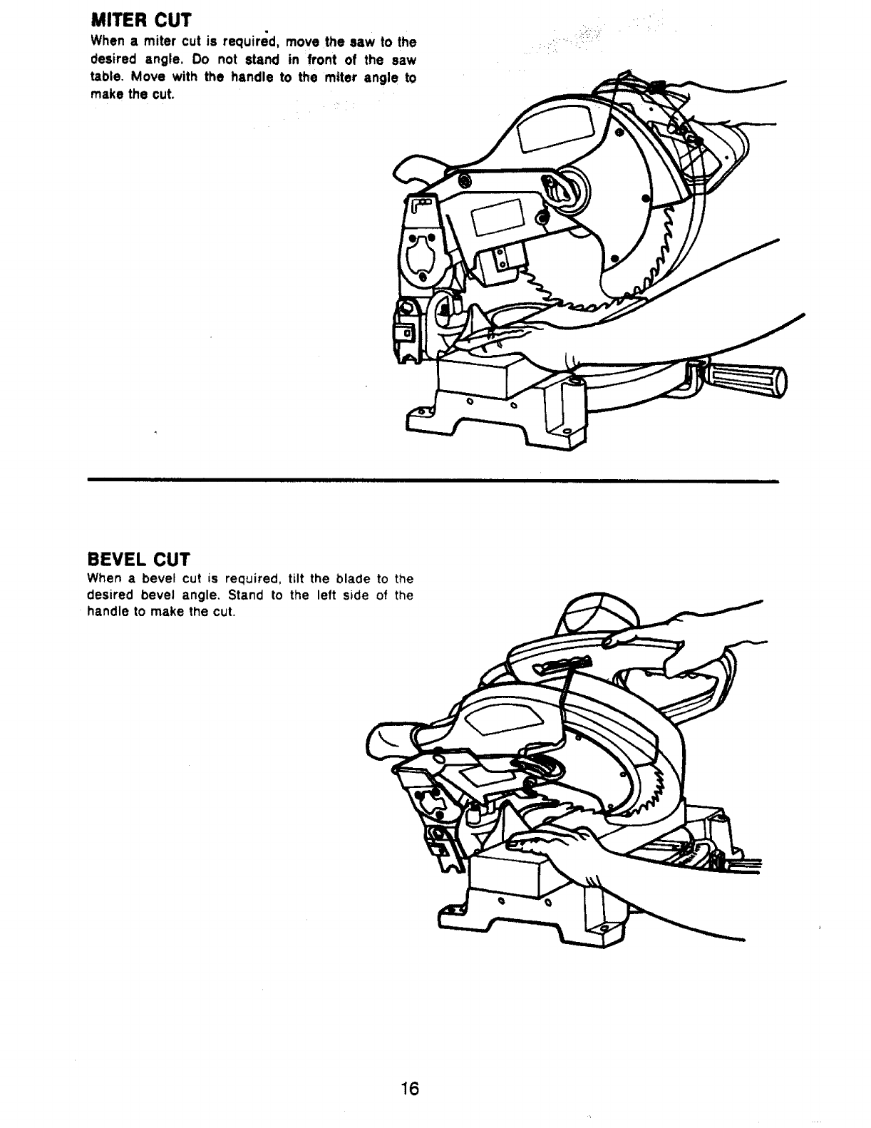
MITER CUT
When a miter cut is required, move the saw to the
cJesired angle. Do not stand in front of the saw
table. Move with the handle to the miter angle to
make the cut.
BEVEL CUT
When a bevel cut is required, tilt the blade to the
desired bevel angle. Stand to the left side of the
handle to make the cut.
16
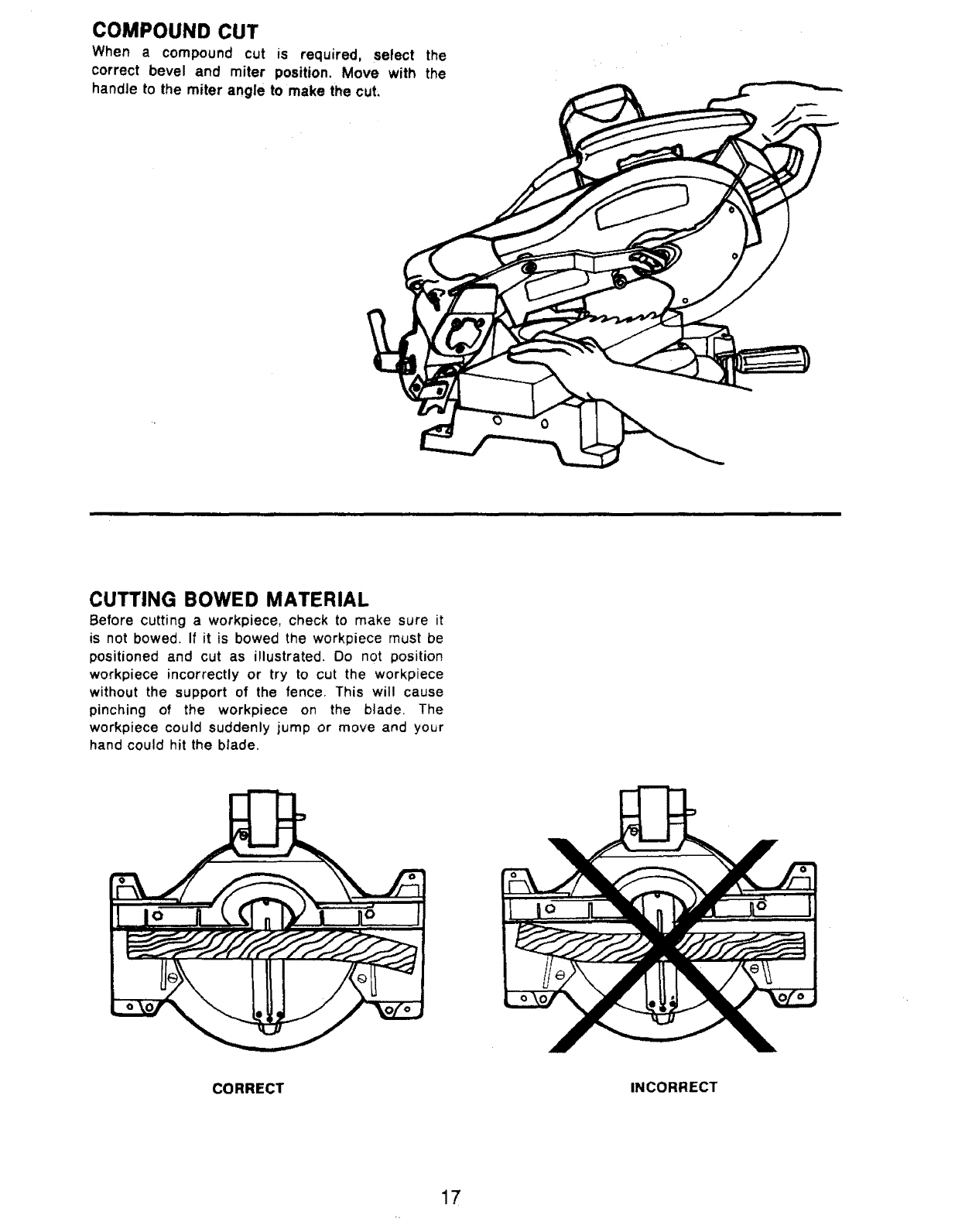
COMPOUND CUT
When a compound cut is required, select the
correct bevel and miter position. Move with the
handle to the miter angle to make the cut:
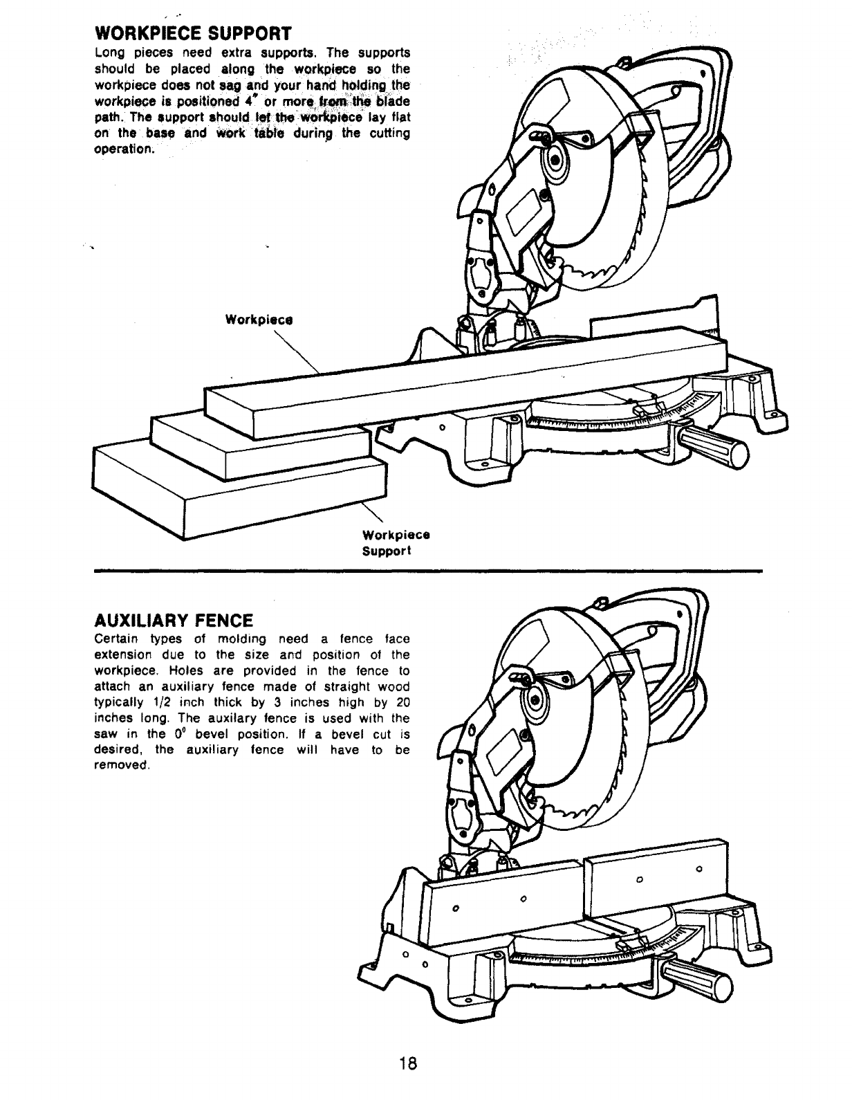
CUTTING BOWED MATERIAL
Before cutting a workpiece, check to make sure it
is not bowed. If it is bowed the workpiece must be
positioned and cut as illustrated. Do not position
workpiece incorrectly or try to cut the workpiece
without the support of the fence. This will cause
pinching of the workpiece on the blade. The
workpiece could suddenly jump or move and your
hand could hit the blade.
CORRECT INCORRECT
17
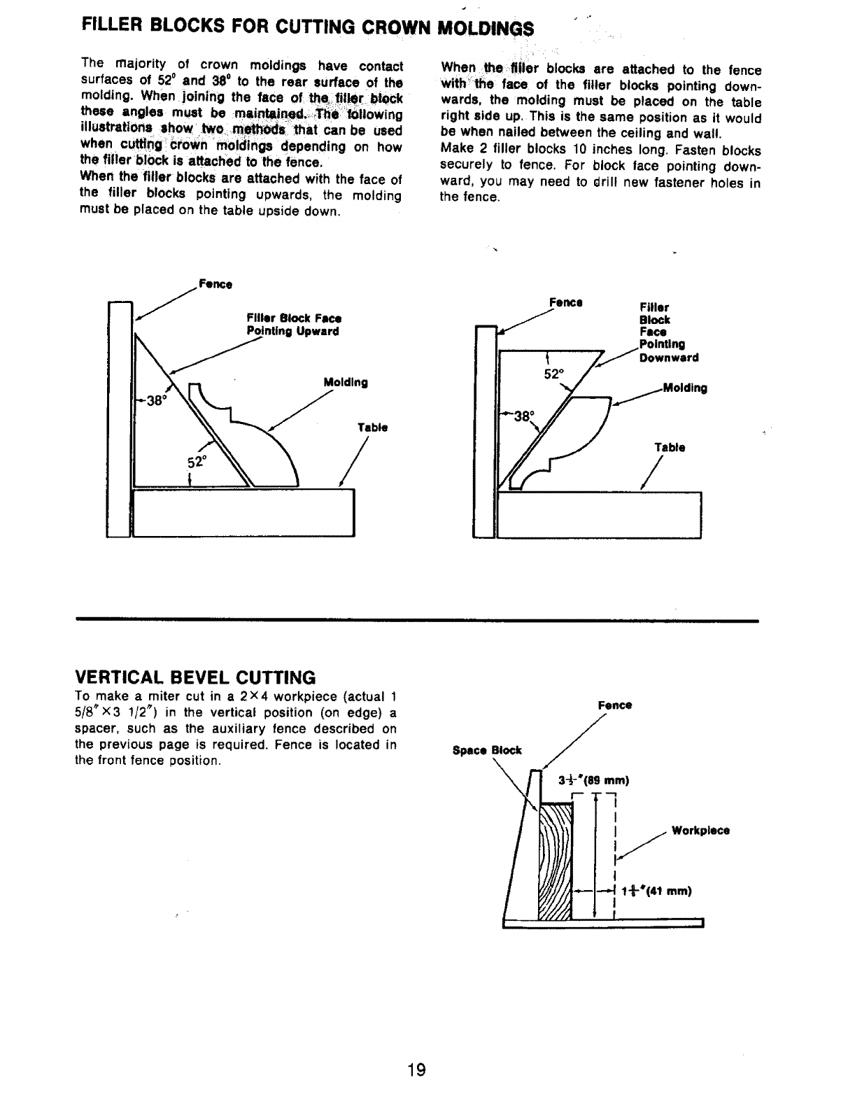
WORKPIECE SUPPORT
Long pieces need extra supports. The supports
should be placed along the workpiece so the
workpiece does not sag and your hand holding the
workp=ece is positioned 4 or mor_ _mit_ blade
path.i The support should I_thewo_iece _lay flat
on the base and work t&bie durin_g the cutting
operation;
Workpiece
Workpiece
Support
AUXILIARY FENCE
Certain types of molding need a fence face
extension due to the size and position of the
workpiece. Holes are provided in the fence to
attach an auxiliary fence made of straight wood
typically 1/2 inch thick by 3 inches high by 20
inches long. The auxitary fence is used with the
saw in the 0°bevel position. If a bevel cut is
desired, the auxiliary fence will have to be
removed.
o
O
18
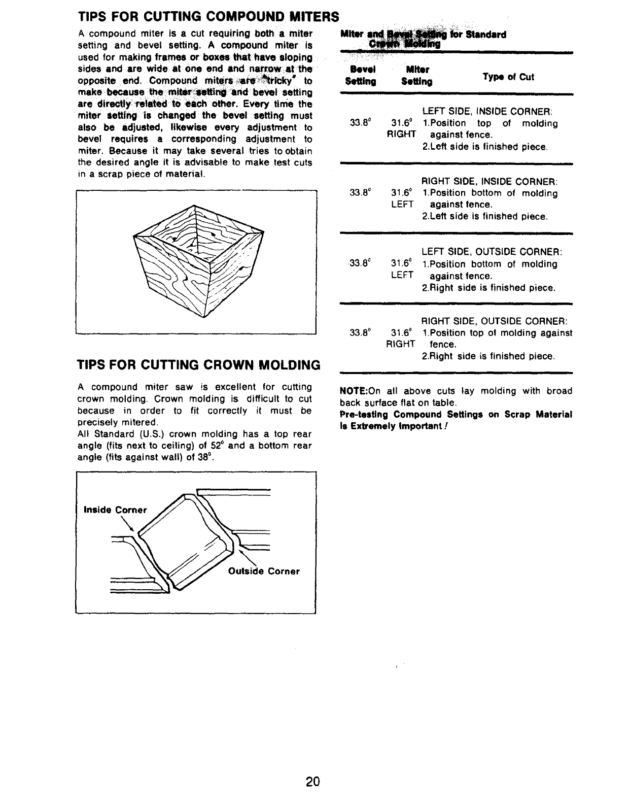
FILLER BLOCKS FOR CUTTING CROWN MOLDINGS
The majority of crown moldings have contact
surfaces of 52o and 38o to the rear surface of the
molding. When•joining the face of :_i!il_r i_
these angles must be mai_ined,:_Thei_ilowing
illustrations show two _m_:that can be used
when cuffing: cr0wn moldings depending on how
the flflerblock is attached to the fence.
When the filler blocks are attached with the face of
the filler blocks pointing upwards, the molding
must be placed on the table upside down.
When the flilar blocks are attached to the fence
wtth_the face of the filler blocks pointing down-
wards, the molding must be placed on the table
right side up, This is the same position as it would
be when nailed between the ceiling and wail.
Make 2 filler blocks 10 inches long. Fasten blocks
securely to fence, For block lace pointing down-
ward, you may need to drill new fastener holes in
the fence.
Filler 8lock Face
Pointing Upward
Molding
Table
/iL
Fence Filler
SBlock
Face
Pointing
_jDownward
.,..38__ M°ld|ng
1
i ii i i i i iiiiiiiiiiiiiiiiiiiiiiiiii iiiiii
VERTICAL BEVEL CUTTING
To make a miter cut in a2x4 workpiece (actual 1
5/8"x3 1/2") in the verticat position (on edge) a
spacer, such as the auxiliary fence described on
the previous page is required. Fence is located in
the front fence position. Space Block
Fence
3-_-"(89 mm)
!
li
jWorkpiece
t
/-- --_ 1"_L4'(41ram)
I
f
19
opposite end. Compound mi_rs:_;_re:_i_ky" to
make because the: m_i_S_etti_:_and ' bevel setting
are dir_ly_reiated t0 :each other, Every time the
miter Setting is changed the bevel setting must
also be adjusted, likewise every adjustment to
bevel requires a corresponding adjustment to
miter. Because it may take severat tries to obtain
the desired angle it is advisable to make test cuts
in a scrap piece of material.
TIPS FOR CUTTING COMPOUND MITERS
A compound miter is a cut requiring botha miter Miter i
setting and bevel setting. A compound miter is
used for making frames or boxes that hive sloping .............
sides and are wide at One end lnd. nari_Ow_ the Bevel
Setting
33,8 °
33.80
31.6 °
RIGHT
31.6 °
LEFT
TIPS FOR CUTTING CROWN MOLDING
Miter
Setting Type of Cut
.33.8 ° 31.6 _
LEFT
LEFT SIDE, INSIDE CORNER:
1.Position top of molding
against fence.
2.Left side is finished piece.
33.8o 31.6_
RIGHT
RIGHT SIDE, INSIDE CORNER:
1.Position bottom of molding
against fence,
2.Left side is finished piece.
LEFT SIDE, OUTSIDE CORNER:
1.Position bottom of molding
against fence.
2.Right side is finished piece.
RIGHT SIDE, OUTSIDE CORNER:
1.Position top of molding against
fence.
2.Right side is finished piece.
A compound miter saw !s excellent for cutting
crown molding. Crown molding is difficult to cut
because in order to fit correctly it must be
precisely mitered.
All Standard (U.S.) crown molding has a top rear
angle (fits next to ceiling) of 52° and a bottom rear
angle (fits against wall) of 380.
NOTE:On all above cuts lay molding with broad
back surface flat on table.
Pre-testing Compound Settings on Scrap Material
Is Extremely Important !
i,cornr
2O
Maintaining Your
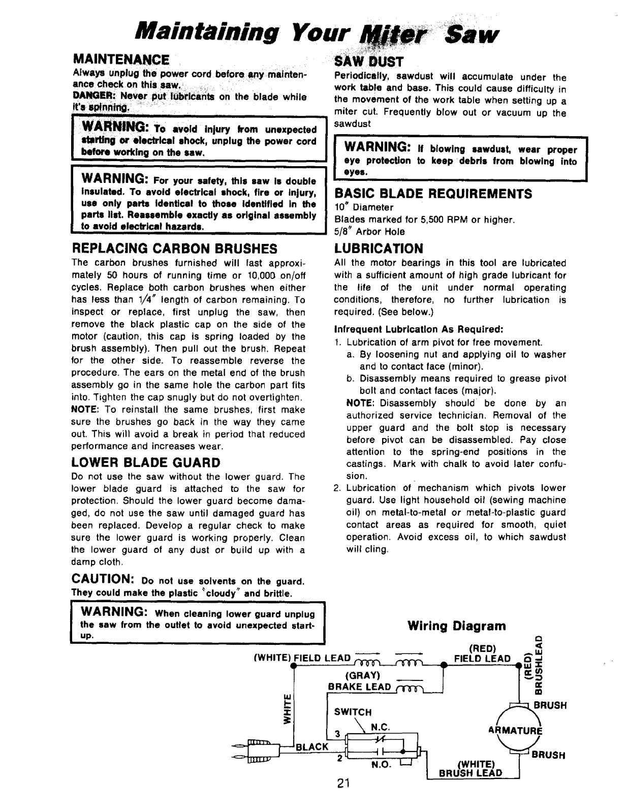
MAINTENANCE
Atways unplug the power cord before imymatnten,
ance check on this SaW.i_.... :_.... i::......
DANGEI=h Never put I_bricants on the blade while
.o""...,°,;; ,m
mrUng or electrical shock, unplug the
power, cord I
| bef_ wo,_ing on the saw.
iiiiii iiii i ii
I WARNING: For your safety, this saw Is double
I Insulated. To avoid electrical shock, fire or injury,
I use only parts Identical to those Identified in the
I parts list. Reassemble exactly as original assembly
| to avoid electrical hazards.
i iiiiiiii i iiiiiiiiiiiii i iiiii iiii lllliHii
OUST
Periodically, sawdust will accumulate under the
work table and base. This could cause difficulty in
the movement of the work table when setting up a
miter cut. Frequently blow out or vacuum up the
sawdust
i iiiiiiiii ] i iii i
WARNING: If blowing sawdust, wear proper
eye protection to keep debris from blowing into /
eyes. iiiiii iiii
BASIC BLADE REQUIREMENTS
10_Diameter
Blades marked for 5,500 RPM or higher.
5/8 '1Arbor Hole
REPLACING CARBON BRUSHES
The carbon brushes furnished will fast approxi-
mately 50 hours of running time or 10,000 on/off
cycles, Replace both carbon brushes when either
has less than 1/4 _ length of carbon remaining. To
inspect or replace, first unplug the saw, then
remove the black plastic cap on the side of the
motor (caution, this cap is spring loaded by the
brush assembly). Then pull out the brush. Repeat
for the other side. To reassemble reverse the
procedure. The ears on the metal end of the brush
assembly go in the same hole the carbon part fits
into. Tighten the cap snugly but do not overtighten.
NOTE: To reinstall the same brushes, first make
sure the brushes go back in the way they came
out. This will avoid abreak in period that reduced
performance and increases wear.
LOWER BLADE GUARD
Do not use the saw without the lower guard. The
lower blade guard is attached to the saw for
protection. Should the lower guard become dama-
ged, do not use the saw until damaged guard has
been replaced. Devetop a regular check to make
sure the lower guard is working properly. Clean
the lower guard of any dust or build up with a
damp cloth,
LUBRICATION
All the motor bearings in this tool are lubricated
with asufficient amount of high grade lubricant for
the life of the unit under normal operating
conditions, therefore, no further lubrication is
required. (See below.)
Infrequent Lubrication As Required:
t. Lubrication of arm pivot for free movement.
a. By loosening nut and applying oil to washer
and to contact face (minor).
b, Disassembly means required to grease pivot
bolt and contact faces (major).
NOTE: Disassembly should be done by an
authorized service technician. Removal of the
upper guard and the bolt stop is necessary
before pivot can be disassembled. Pay close
attention to the spring-end positions in the
castings. Mark with chalk to avoid later confu-
sion.
2. Lubrication of-mechanism which pivots lower
guard. Use light household oil (sewing machine
oi!) on metal-to-metal or metal-to-plastic guard
contact areas as required for smooth, quiet
operation. Avoid excess oil, to which sawdust
will cling,
CAUTION: Do not use solvents on the guard.
They could make the plastic 'cloudy" and brittle.
iii ii ii i
WARNING: When cleaning lower guard unplug
the saw from the outlet to avoid unexpected start-
up. i===ll i= 11
(WHITE
Wiring Diagram cl
(RED)
FIELD LEAD _ _ .. FIELD LEAD _'_
.... v, ,----_ , v,.........w "' _.UJ .J=
(GRAY) I I _v
BRAKE LEAD _ / m_
ISWITCH
I'= X N.C. ARMATURE
,, n-,_x---,I \. )
;_ _ BRUSH
2_ ' _-
N---_-_-! (WHITE) I -"
[ BRUSH LEAD J
21
1
!4
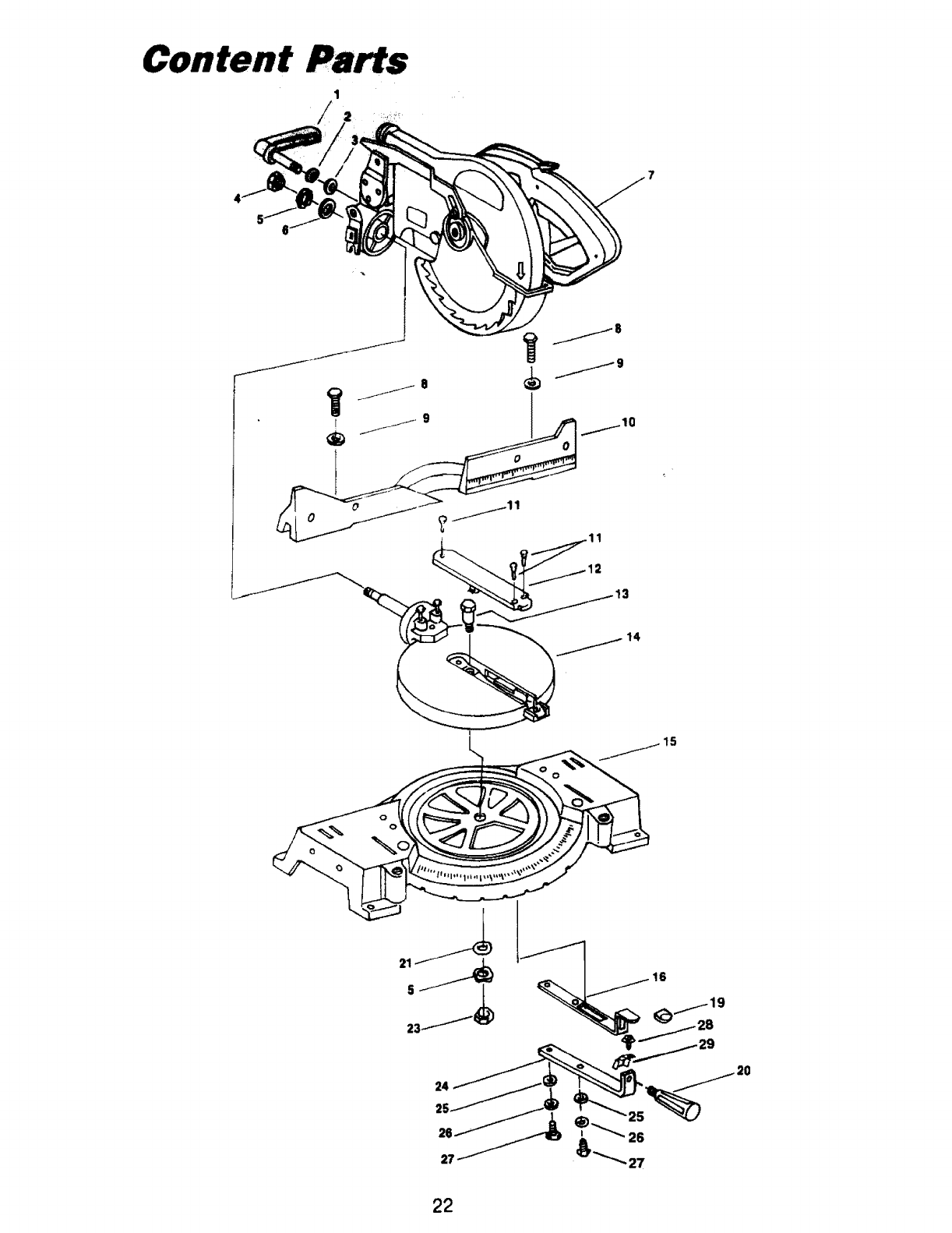
Content Parts
,, ........ .,,. ,,
I9o02 ;ooi
2 021203-001
3 021109-001
4 022300-001
5 021611-000
6021117-001
7900430-000
8 020314-005
9 021120-003
10 224037-000
11 020804-0()0
12 303188-000
13 028304-003
14 900475-000
,,,,, H ........
....... ":: "I ...............
:Part No,
•,,,,.......... , , ,
Fief. No.
Bevel Lock Knob
Spring Washer
Flat Washer
Nut
Wave Washer (2)
Flat Washer
Blade Guard Asm.
Screw 12)
Washer /2)
Fence
Screw (3)
Table Insert
Bolt. Shoulder
Table Assembly
15 221013-000
16 270305-000
19 303229-000
20 303018-004
21 021117-001
23 022300-001
24 224050-000
25 021120-003
26 021204-003
27 020314-009
28 020701-009
29 270316-000
,i
Description
Base
Spring Index
Grip Miter Index
Handle-Miter
Washer -.
Nut
Arm-Miter
Washer (2)
Spring Washer (2)
Hex HD. Screw (2)
ScrewlWasher
Plate-Clamp
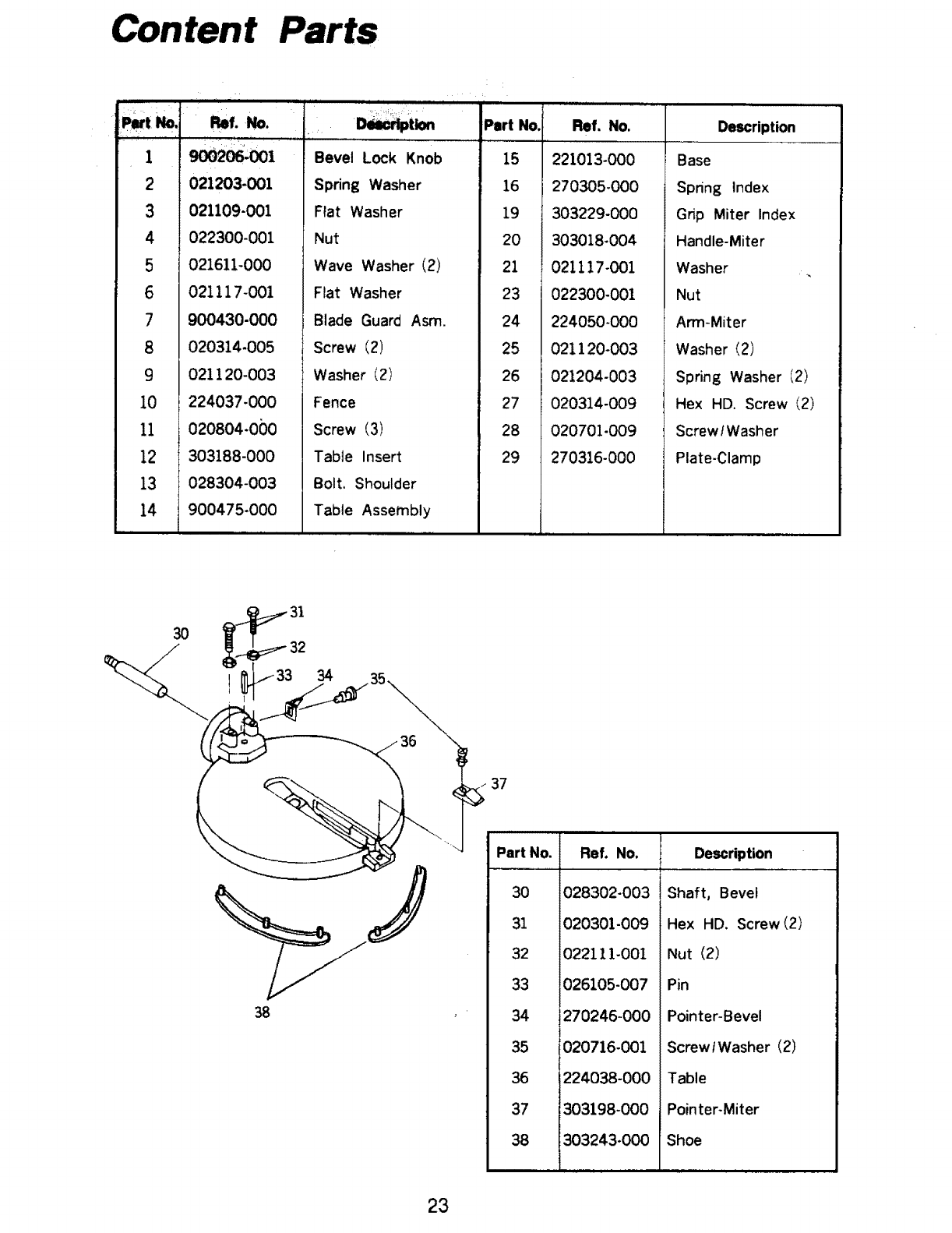
30
38
37
Part No.
30
31
32
33
34
35
36
37
38
Ref. No,
028302-003
020301-009
022111-001
!026105-007
270246-000
!020716-001
1224038-000
_303198-000
1303243-000
Description
Shaft, Bevel
Hex HD. Screw (2)
Nut (2)
Pin
Pointer-Bevel
Screw/Washer (2)
Table
Pointer-Miter
Shoe
23
\\\
0
onto
\
\
\
\
/
24

tl" •
IE
,,,,,,
rio
v e"
i,) el)
_,NN _.am_m o m m ,," m ,.,
8_888_8_8888
• _88_8=8=88 888_ °
°999999999_999 99999999.'9_
v I_ 0 .£:
= _o_ a.7 _ Z-_-_ _'
: _ rd_ r,,_ _l:l Z €.,D _:l. ._ _ _ _ _ _ _
___=
25
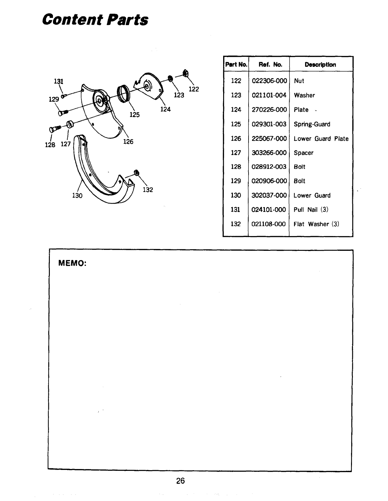
Content
131
129
125 124
123 122
Part No,
122
123
124
125
126
127
128
129
130
131
132
Ref. No,
022306-000
021101-004
270226-000
029301-003
225067-000
303266-000
028912-003
020906-000
302037-000
024101-000
021108-000
Delcriptlon
Nut
Washer
Plate -
Spring-Guard
Lower Guard Plate
Spacer
Bolt
Bolt
Lower Guard
Pull Nail (3)
Flat Washer (3)
,k
MEMO:
26
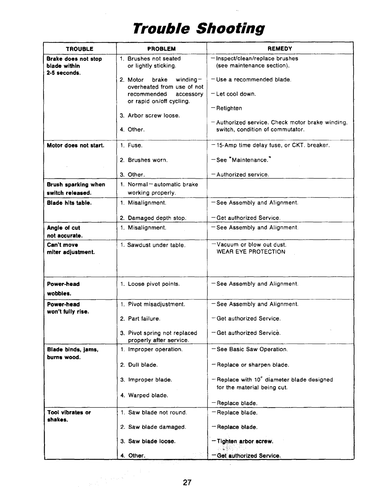
Trouble Shooting
TROUBLE
Brake does not stop
blade within
2-5 seconds.
Motor does not start.
PROBLEM
1. Brushes not seated
or lightly sticking,
,
Angle of cut
not accurate.
Can't move
miter adjustment.
Motor brake winding-
overheated from use of not
recommended accessory
or rapid on/off cycling.
3. Arbor screw loose.
4. Other.
!, Fuse.
2. Brushes worn.
3. Other.
Brush sparking when !. Normal--automatic brake
switch released, working properly.
Blade hits table. 1, Misalignment, -See Assembly and Alignment.
2. Damaged depth stop. -Get authorized Service.
1. Misalignment. -See Assembly and Alignment.
1. Sawdust under table, --Vacuum or blow out dust,
WEAR EYE PROTECTION
Power-head
wobbles.
Power-head
won't fully rise.
Blade binds, jams,
burns wood.
Tool vibrates or
shakes.
1. Loose pivot points,
1. Pivot misadjustment,
2. Part tailure.
3. Pivot spring not replaced
..... properly alter service,
1. Improper operation.
2. Dull blade.
3. Improper blade.
4. Warped blade.
1. Saw blade not round.
2. Saw blade damaged.
3. Saw blade loose.
4. Other.
REMEDY
.... insp'_'"t!c'_'_nlrepla'_e_.,_= _. brushes ........
(see maintenance section).
-Use arecommended blade.
-- Let cool down.
- Retighten
-Authorized service. Check motor brake winding,
switch, condition of commutator,
- 15-Amp time delay luse, or CKT. breaker.
-- See =M ai nten ance."
- Authorized service.
-See Assembly and Alignment,
- See Assembly and" Alignment,
-Get authorized Service.
- Get authorized Service.
-See Basic Saw Operation,
-Replace or sharpen blade.
--Replace with 10" diameter blade designed
for the material being cut.
- Replace blade.
- Replace blade.
-- Replace blade.
-Tighten arbor screw.
:_ ; --Get authorized Service.
27

PRO-TECH POWER, INC.
13750 Van Ness Avenue
Gardena, CA 90249
Printed in Taiwan 3/96
