ProSoft Technology IHN RLXIB-IHN, RLXIB-IHN-W, RLXIB-IHN-WC, RLXIB-IH2N, RLXIB-IH2N-W, & RLXIB-ICN User Manual RLXIB IHN User Manual
ProSoft Technology, Inc RLXIB-IHN, RLXIB-IHN-W, RLXIB-IHN-WC, RLXIB-IH2N, RLXIB-IH2N-W, & RLXIB-ICN RLXIB IHN User Manual
Contents
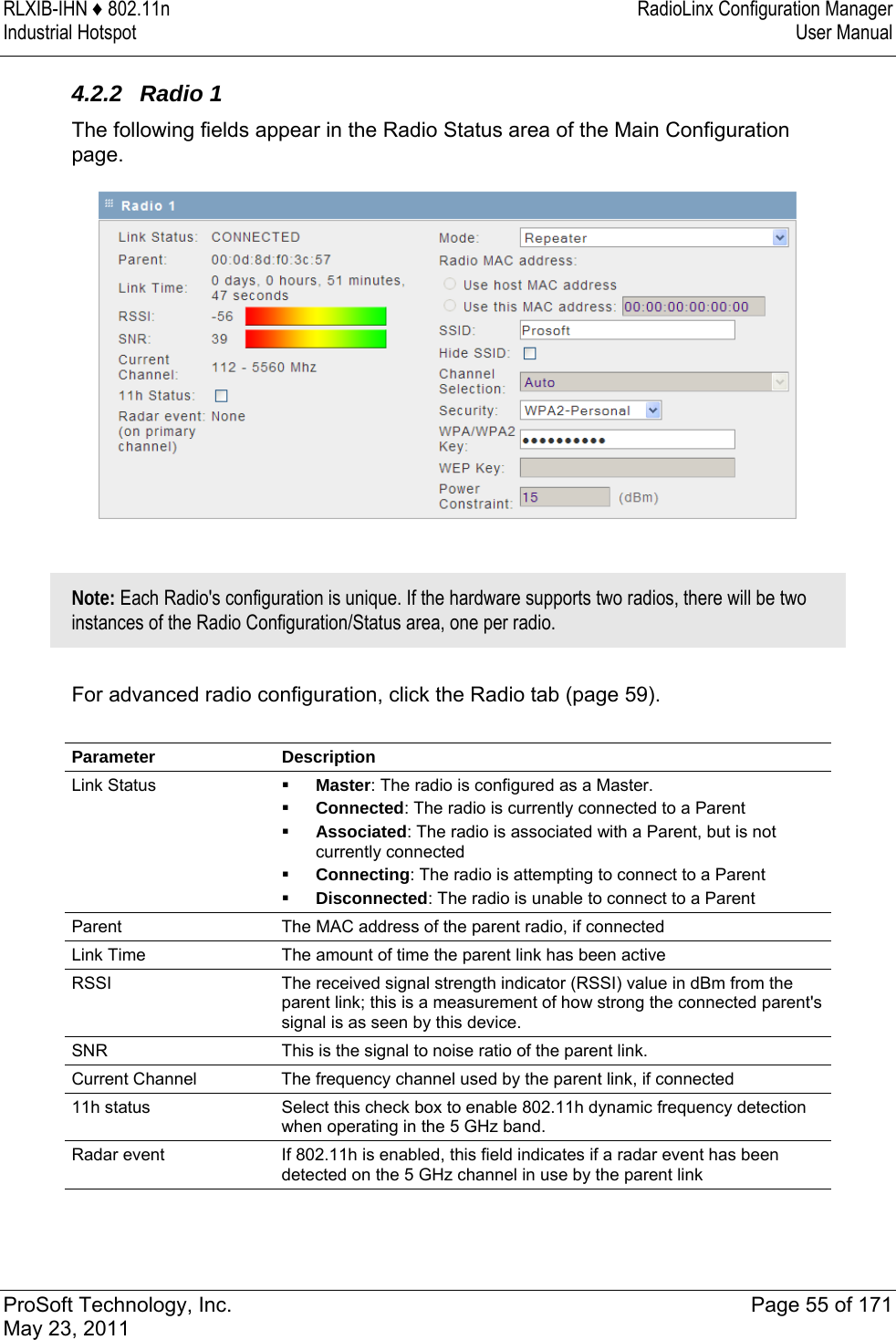
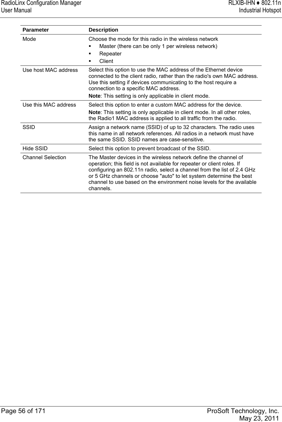
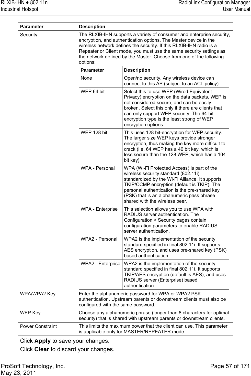
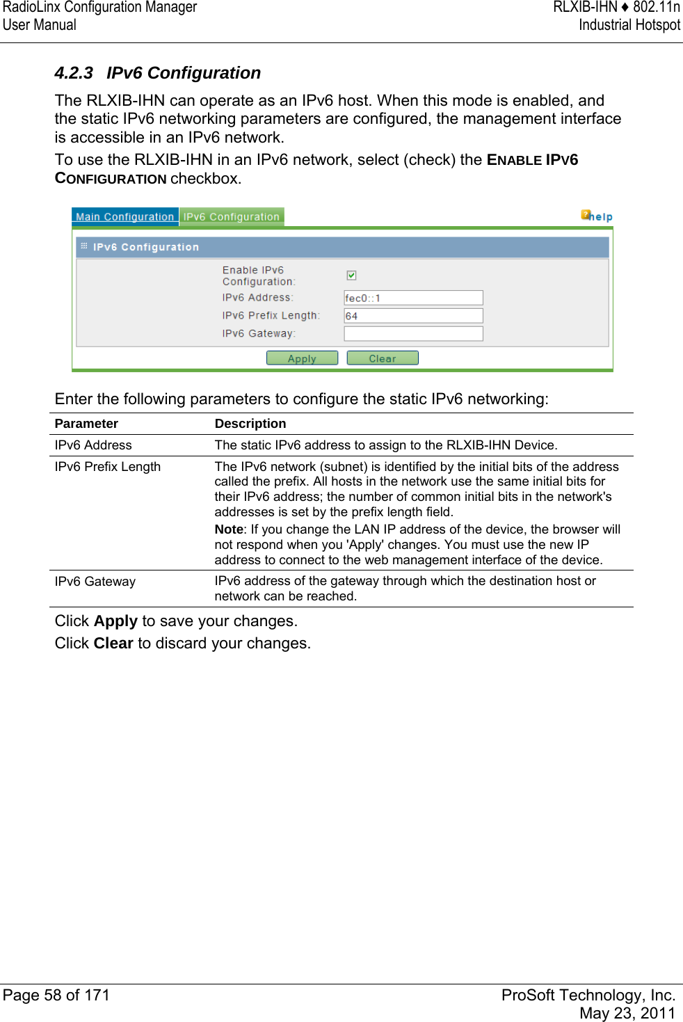
- 1. User Manual
- 2. Updated User Manual
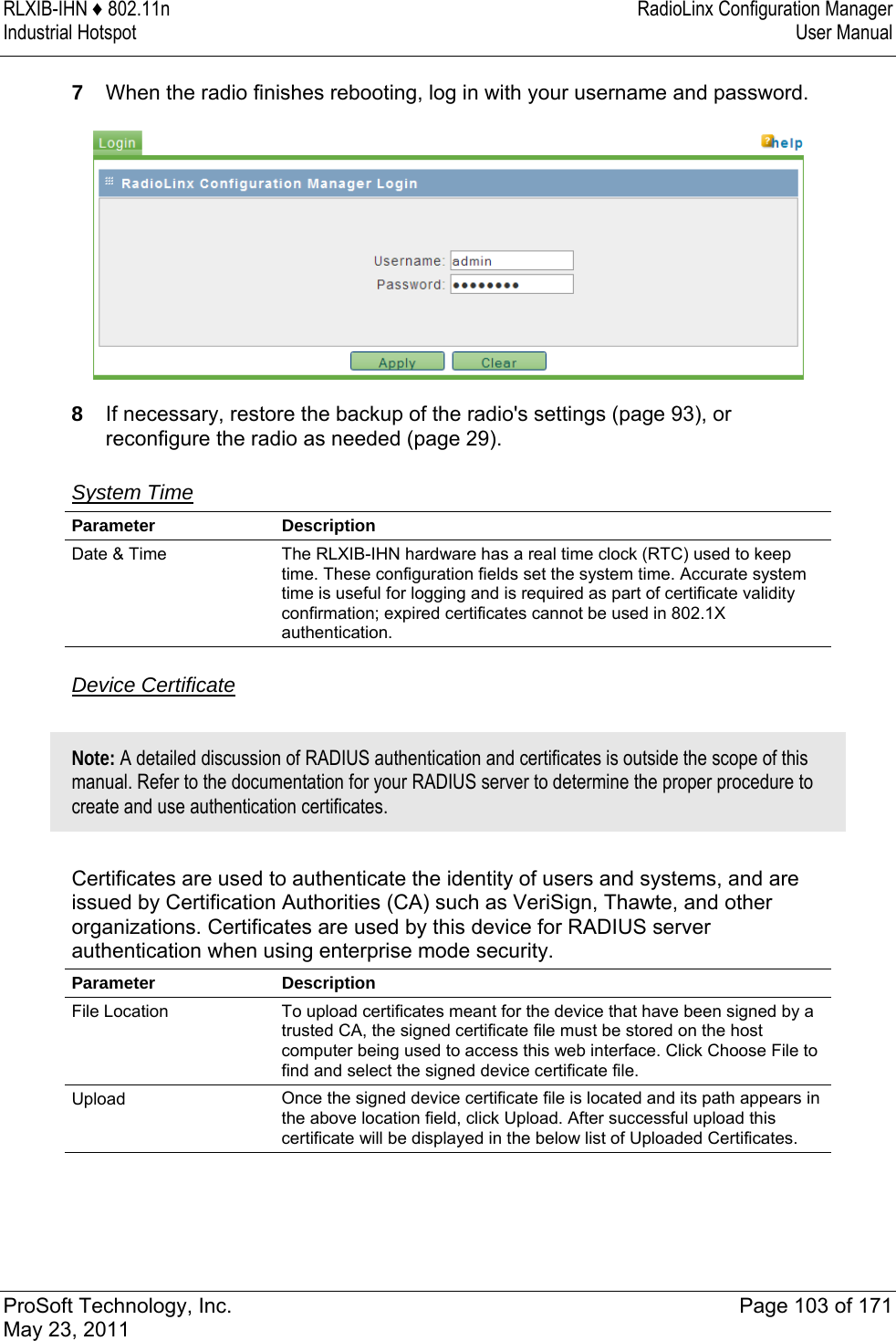
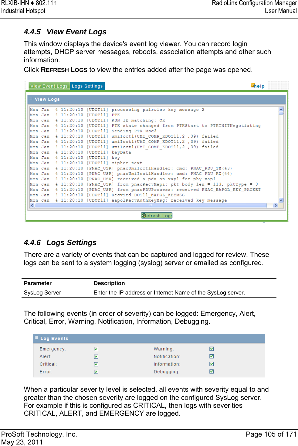
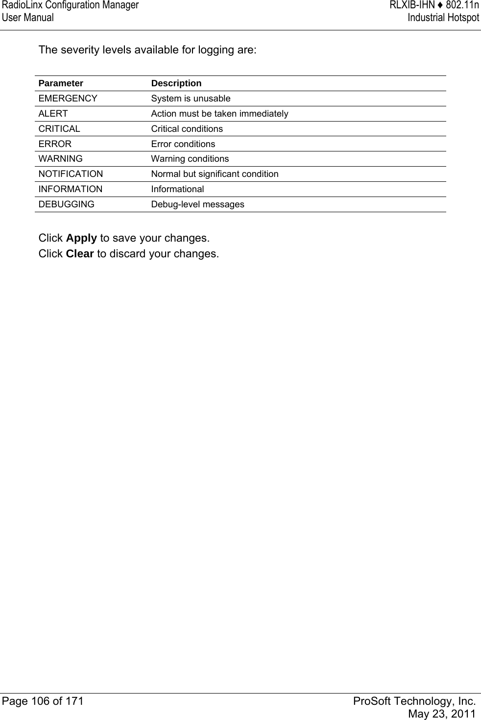
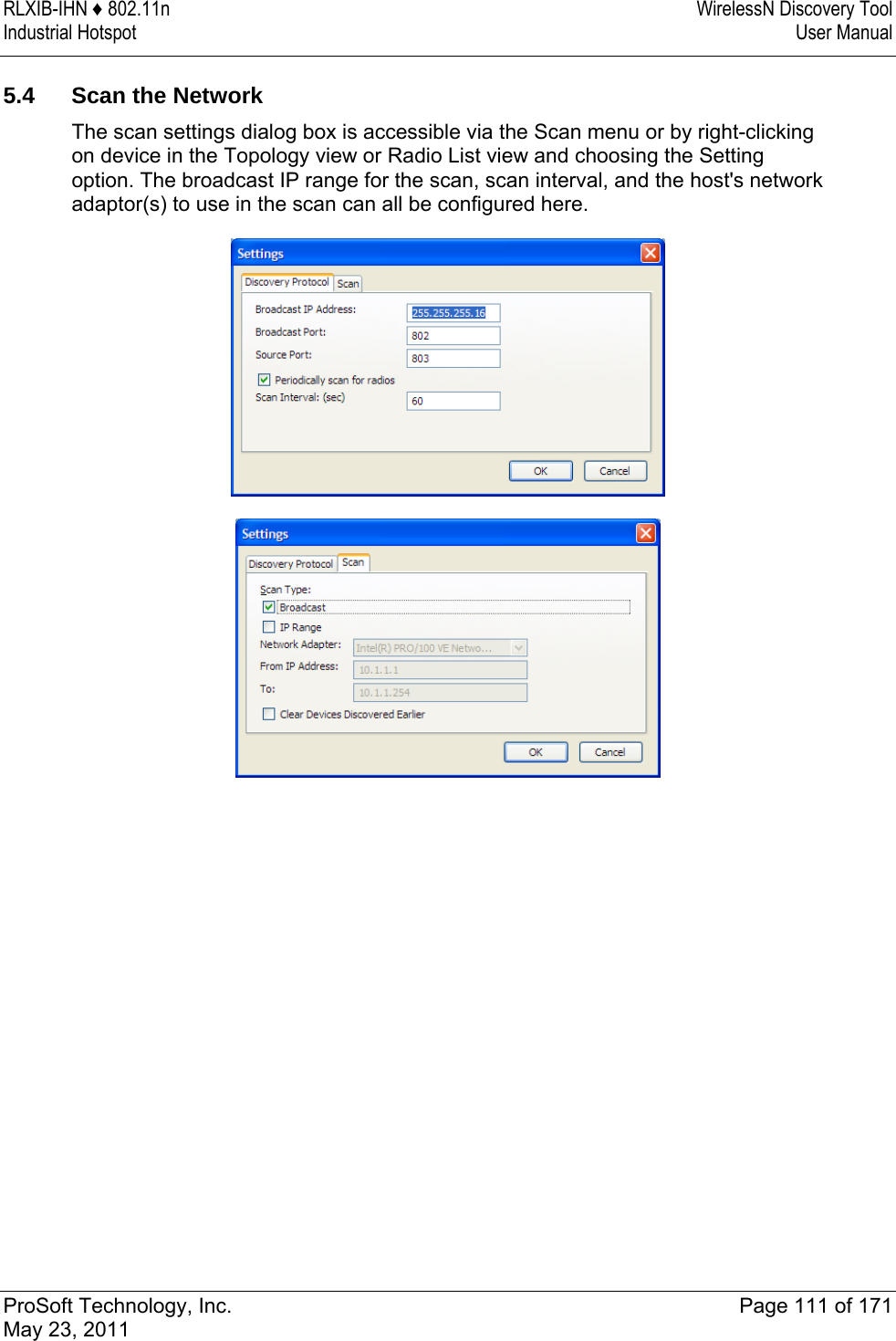
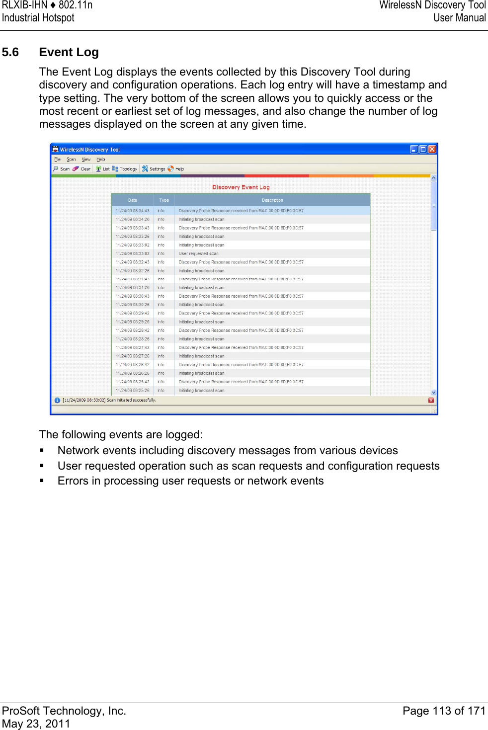
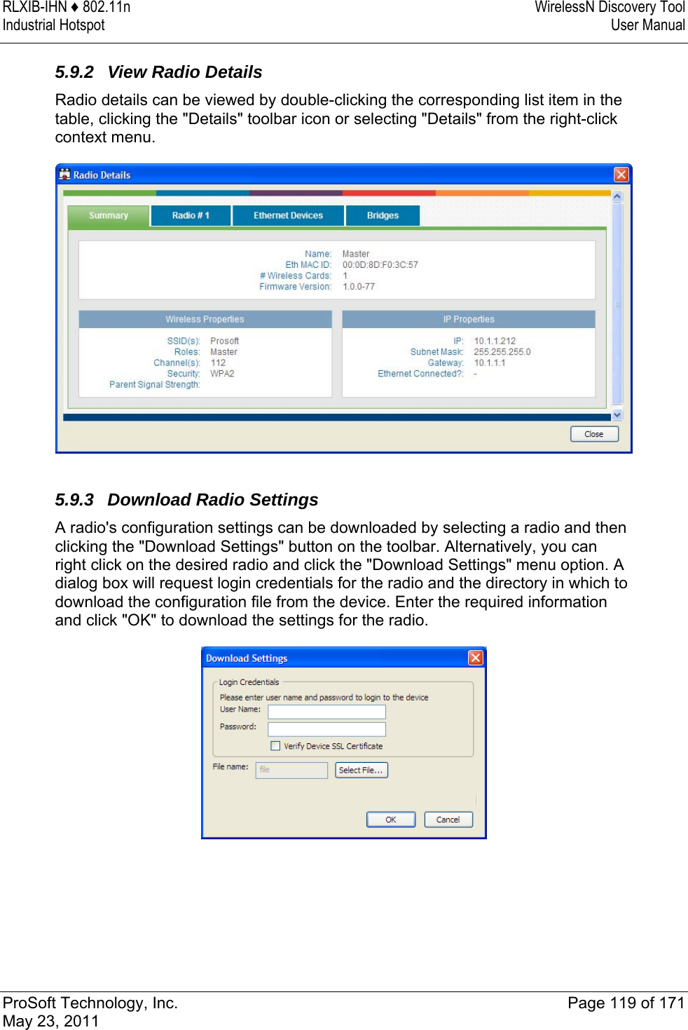
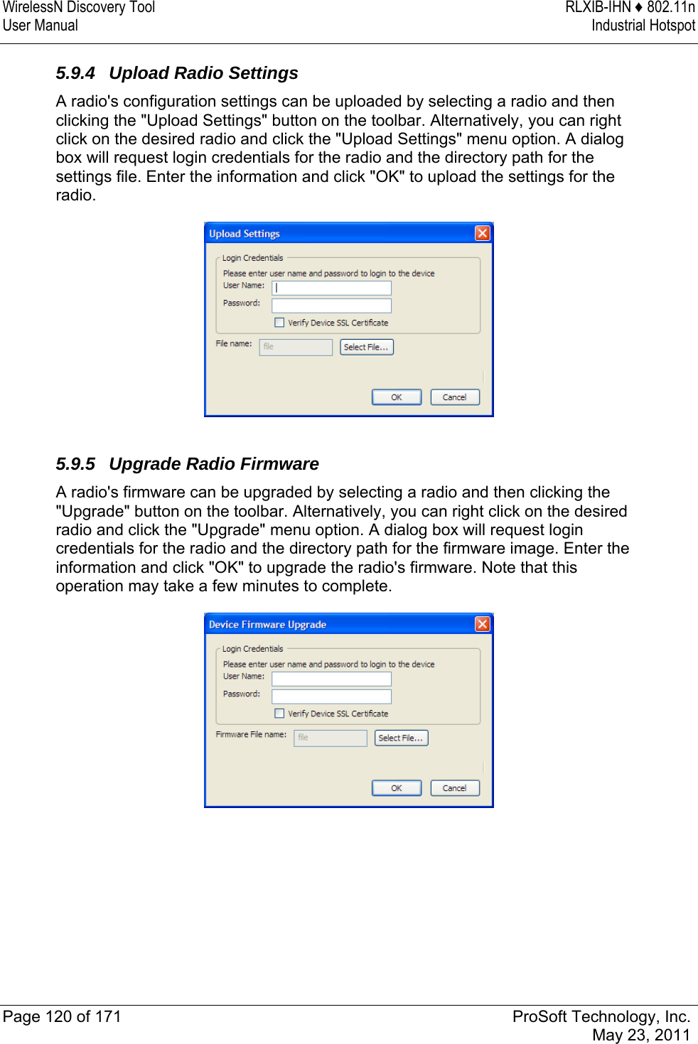
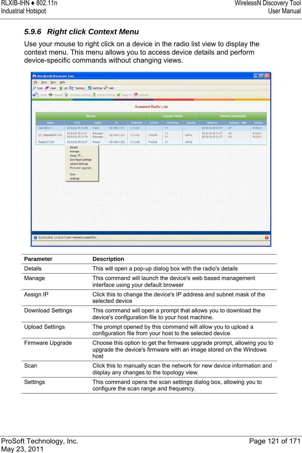
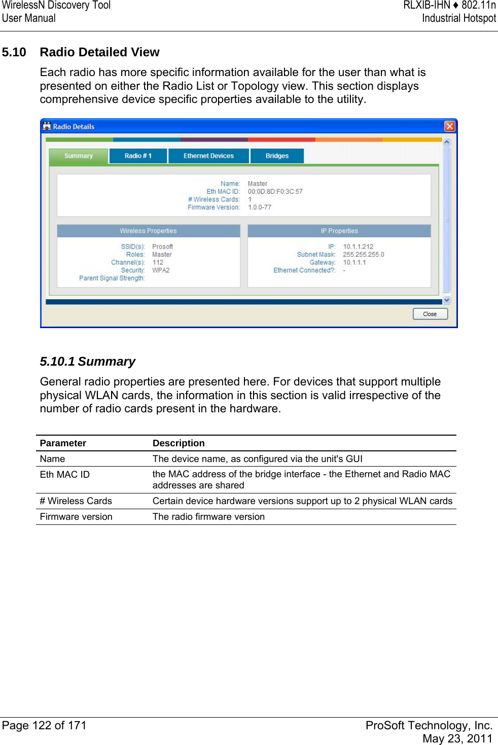
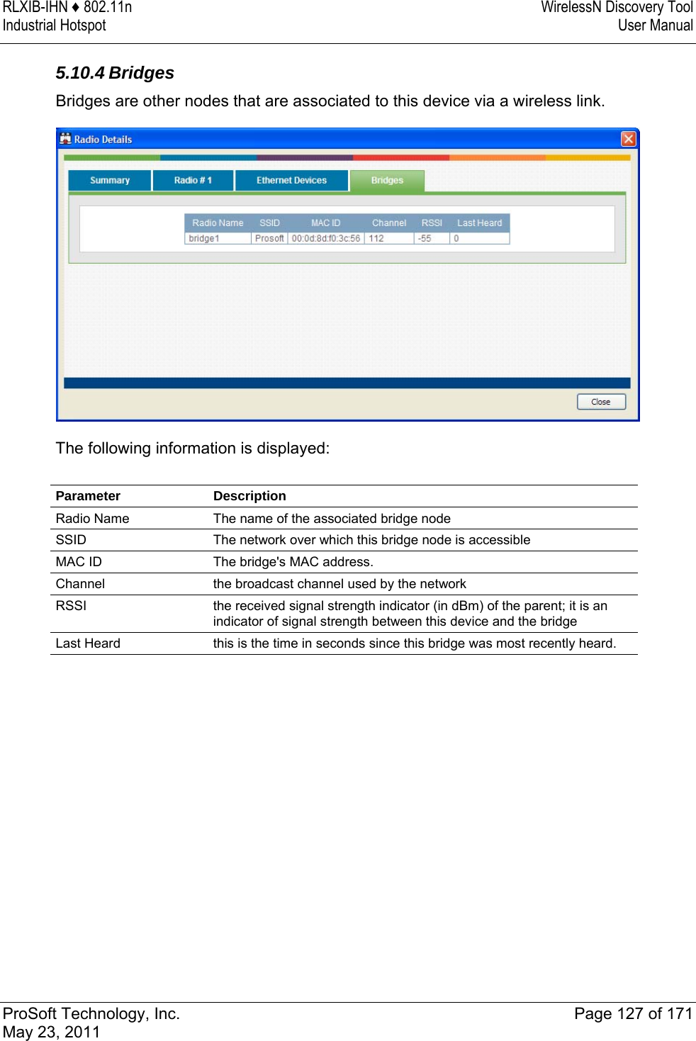
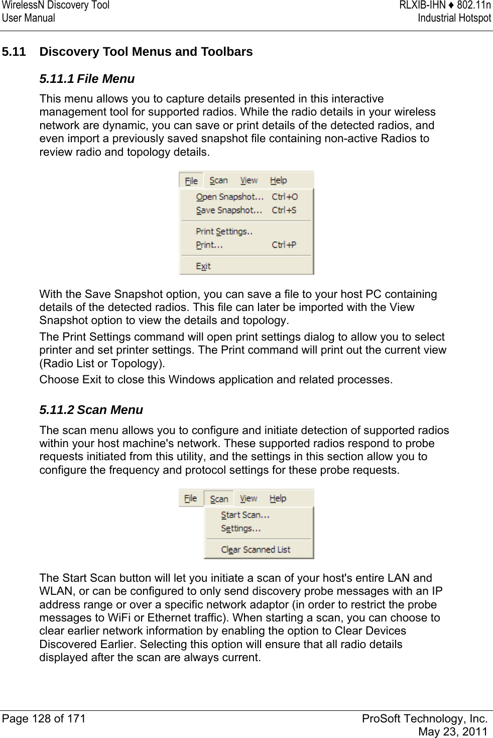
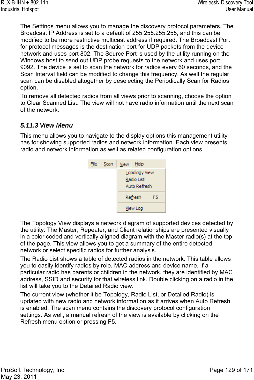
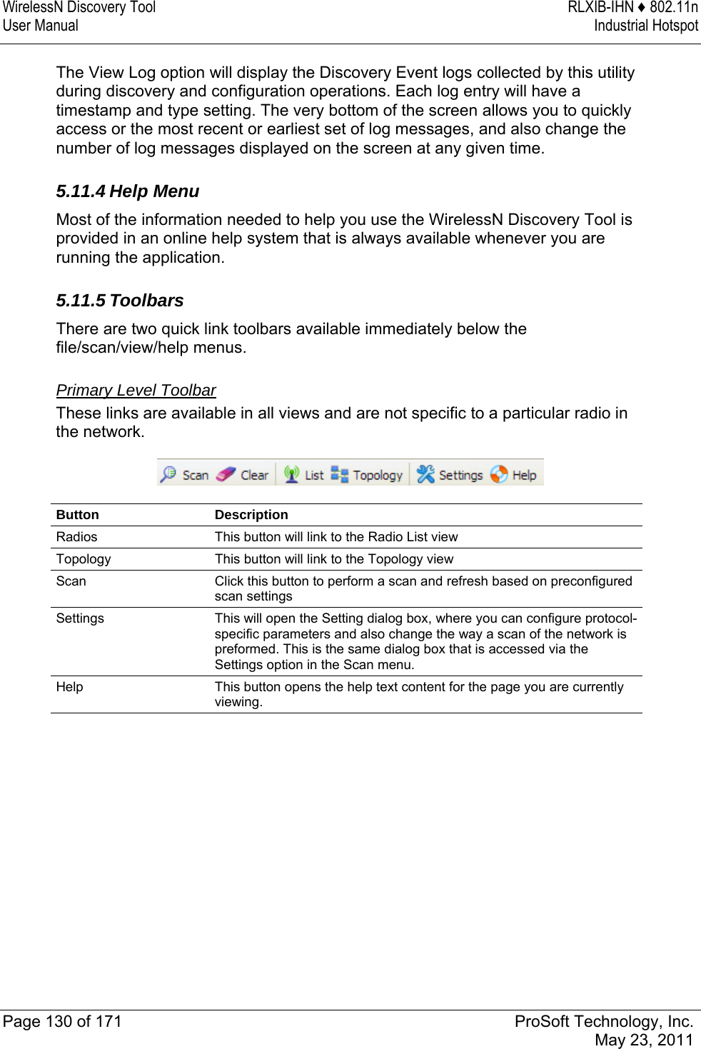
User Manual