Prodrive Technologies SAM2 SAM2 User Manual
Prodrive B.V. SAM2 Users Manual
UserManual.wiki
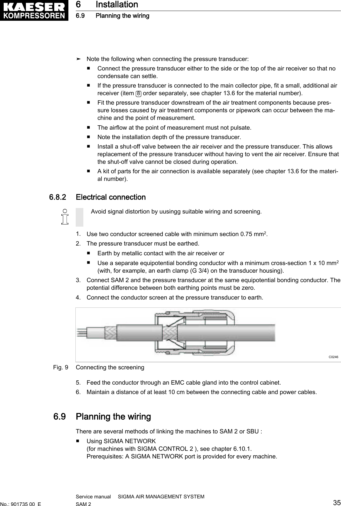
>
Prodrive Technologies
>
SAM2 User Manual
Users Manual
Navigation menu
Upload a User Manual
Namespaces
Wiki Guide
HTML
PDF
Info
Views
User Manual
Discussion / Help
Navigation

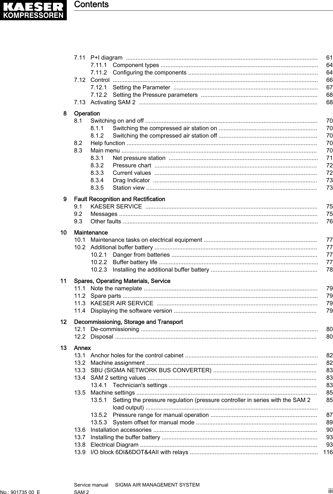

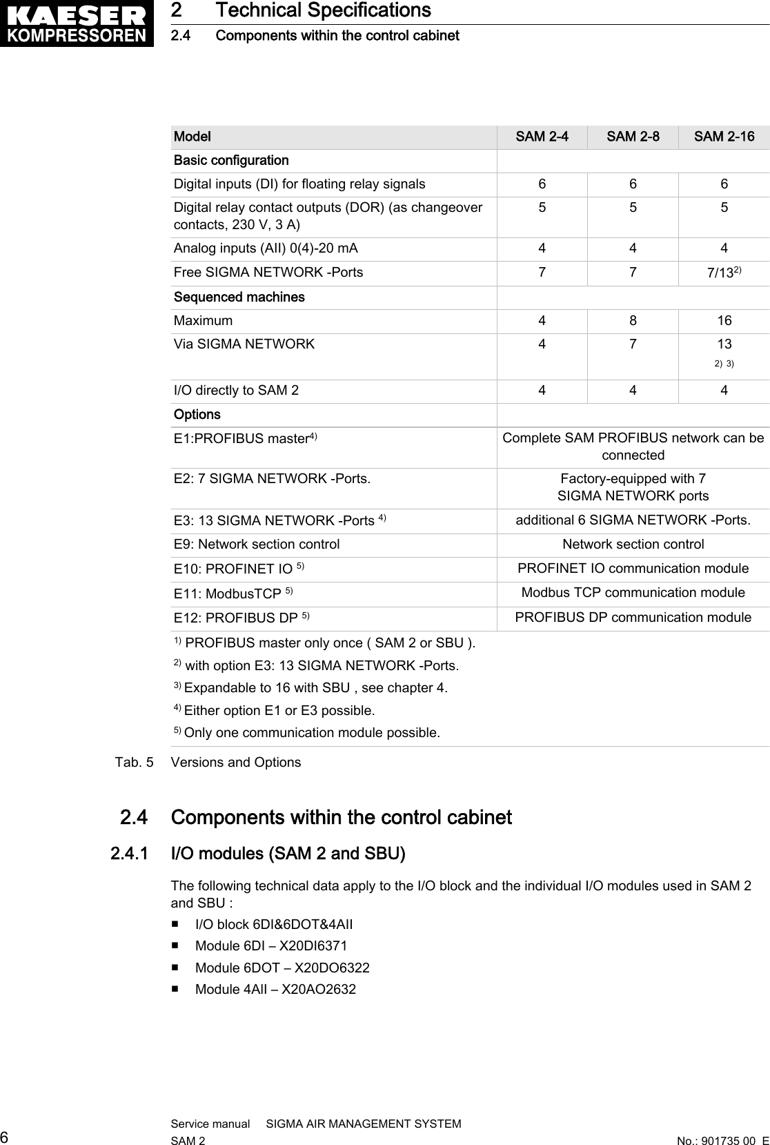
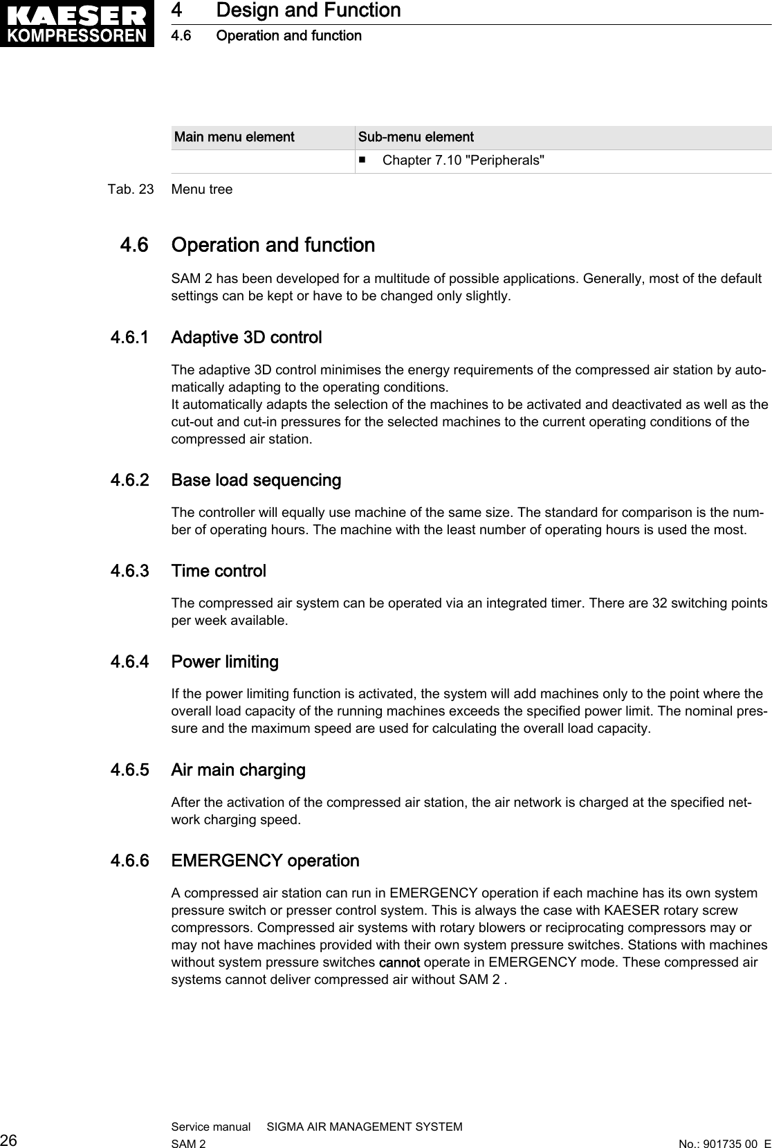
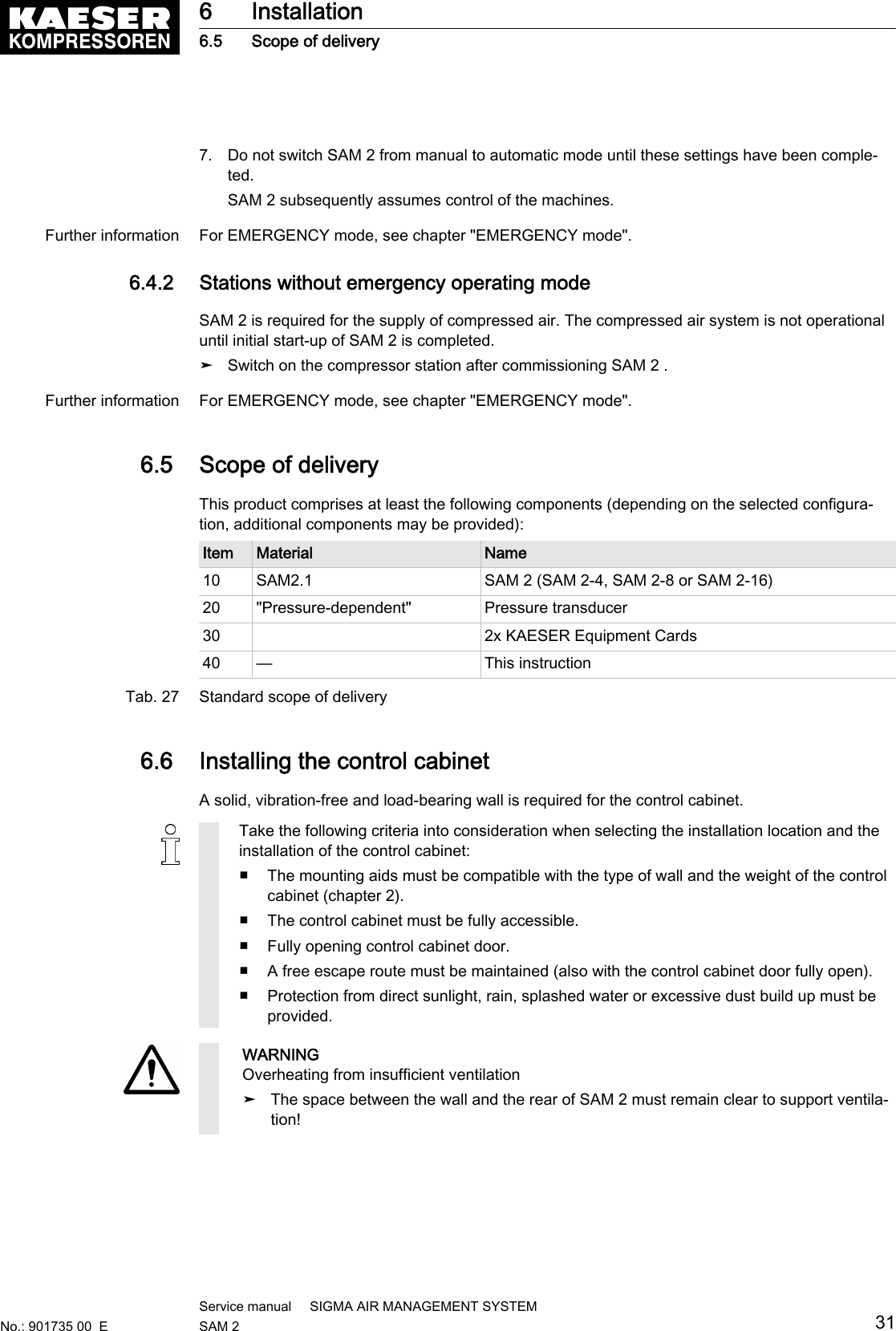
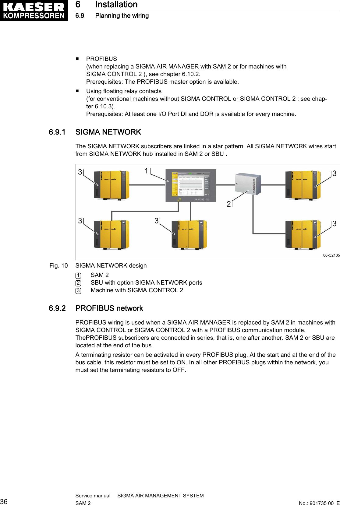
![2 Technical Specifications2.1 System information➤ Enter the system information for SAM 2 in the following table.System information ValueMaterial no.Serial no.Tab. 3 System informationThe nameplate indicates the material no. and serial no.2.2 Electrical DataModel SAM 2 –100-240 V ACSAM 2 – 24 V DCRated voltage [V] 100–240, 50–60 Hz 24Rated current [A] 1.25-0.65 2.5User's fusing [A] 16Power cable core cross-section [mm2]3x1.5Equipotential bond connection [mm2]1x16Enclosure protection IP54 (IEC 529)Buffer batteryBuffer battery [V]/[Ah] 3/0.12Life of buffer battery without power supply [years] 3Life of buffer battery with power supply [years] 10Tab. 4 Electrical Data2.3 Versions and OptionsSAM 2 is available in diverse variants and options:■ In principle, every input and output is freely assignable.■ The number of inputs and outputs can be increased using SBU (see chapter 4)■ Details on assignable and assigned inputs and outputs can be found in the circuit dia‐grams in the annex.2 Technical Specifications2.1 System informationNo.: 901735 00 EService manual SIGMA AIR MANAGEMENT SYSTEMSAM 2 5](https://usermanual.wiki/Prodrive-Technologies/SAM2/User-Guide-2427703-Page-15.png)
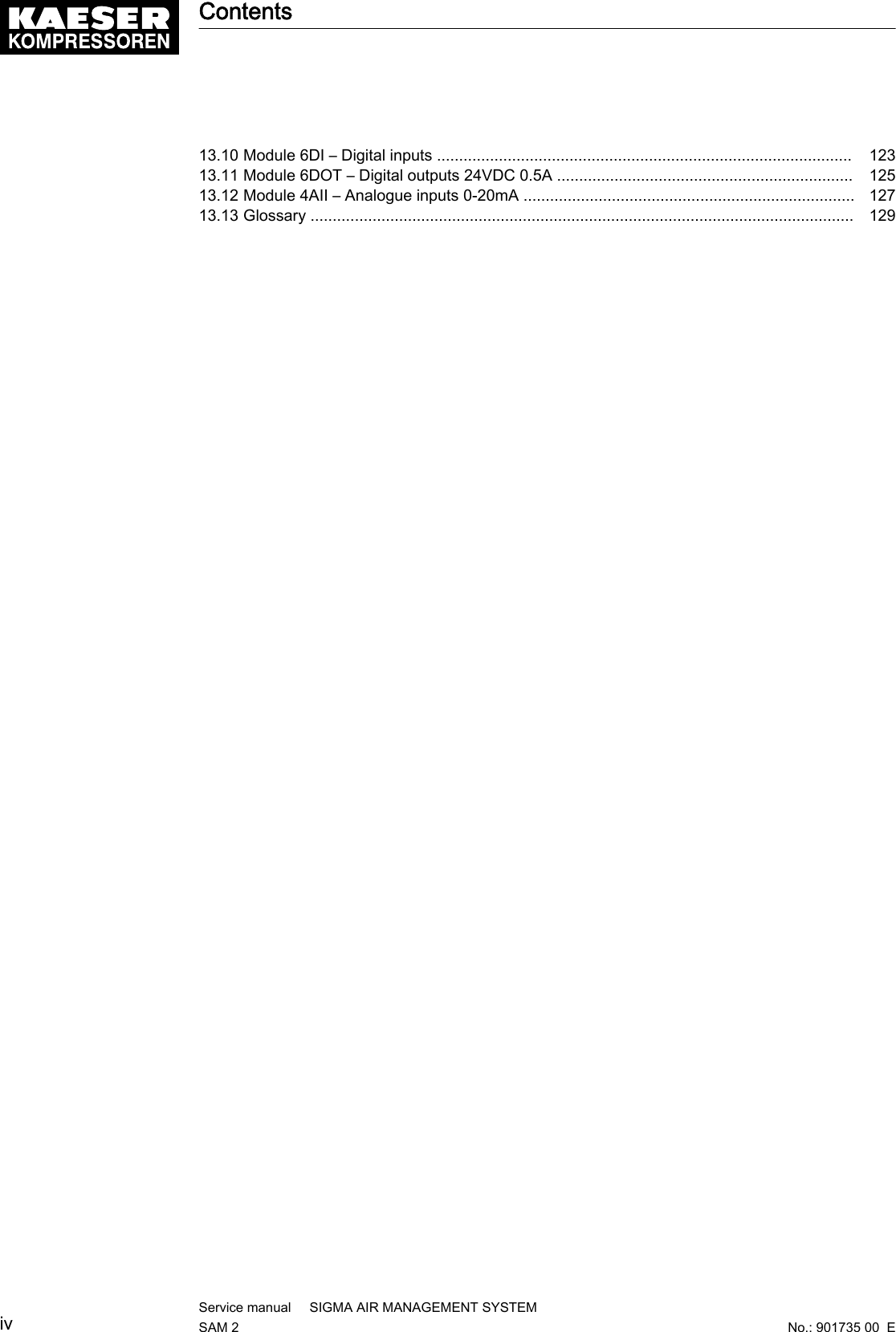
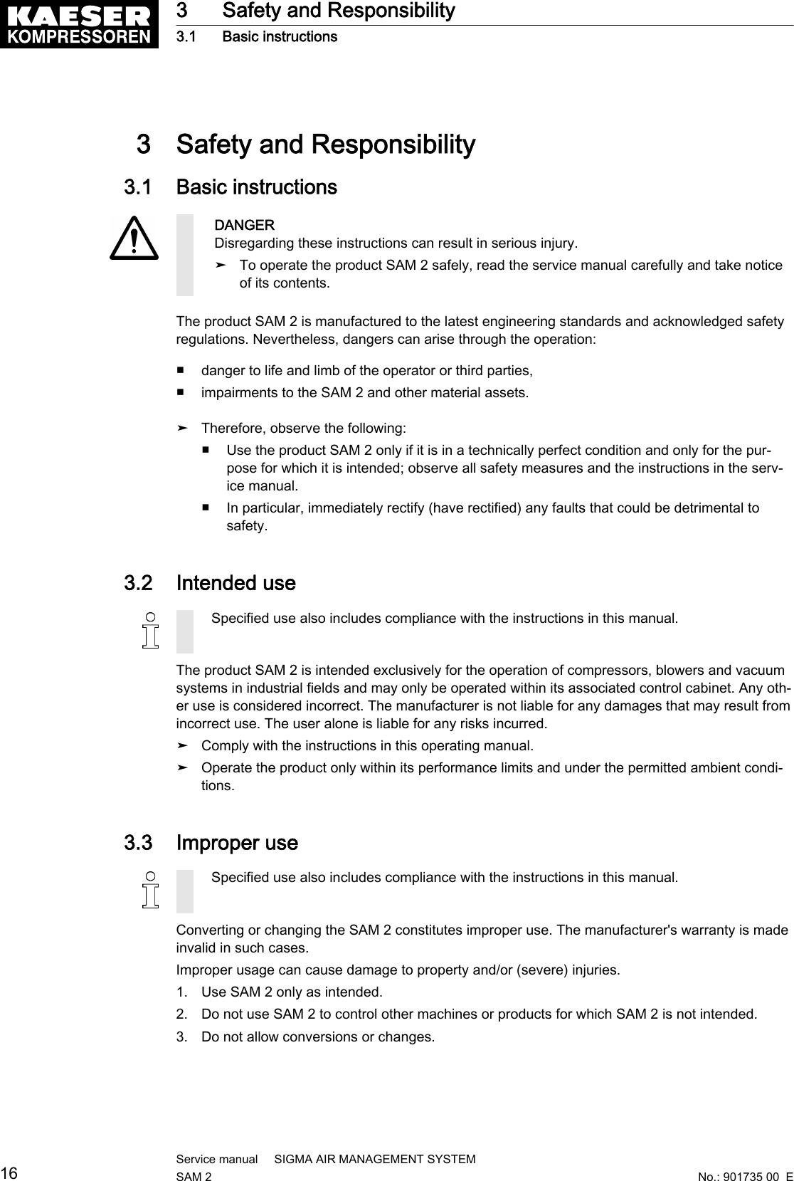
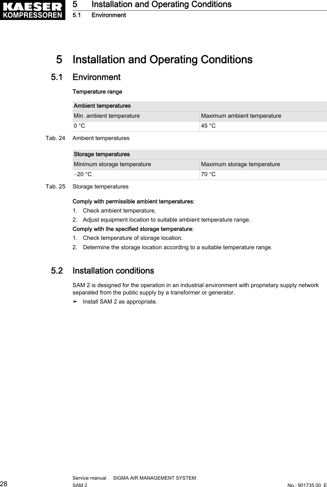
![Technical data, all I/O modulesFeature ValueConnection terminals Push-in terminalConnection diameter■Wire/single-core [mm2]■Flex/fine-core [mm2]■Wire end ferrule [mm2]■Double wire-end ferrule [mm2]Copper wires■ 0.08-2.5 / AWG 28-14■ 0.25-2.5 / AWG 24-14■ 0.25-1.5 / AWG 24-16■ 2x (0.25–0.75)Display elements Status LEDsTab. 6 Technical data, all I/O modulesTechnical data I/O-block and individual modulesFeature ValueBus Controller X20BC0087-C01Bus KAESER SIGMA NETWORKTransfer rate [MBit/s] 10/100Characteristics Auto crossing (Auto-MDI(X) ),Auto negotiationConnections 2 x SIGMA NETWORK -socket RJ45,10/100Base-TXMax. length of the line between two compo‐nents [m]100Electrical isolation SIGMA NETWORK -I/O-moduleYes24 V DC power supply X20PS9400Power supply [V DC], [A] 24 (−15 % / +20 %), max. 0.7Potential separation■ Supply - internal bus■ Supply - I/O module—■ Yes■ NoDigital inputs (DI) Module 6DI – X20DI6371Input voltage [V DC 24 (-15 % / +20 %)Model. Input current at 24 V DC [mA] 3.75Switching threshold [V DC] Low <5 , High >15Insulation voltage between channel and bus[Veff]500Digital outputs (DOT) Module 6DOT – X20DO6322Output voltage [V DC] 24Output current per output maximum (overvolt‐age and short-circuit proof) [A]0.5Output protection Thermal shut-down at overvoltage or short-cir‐cuit, integrated protection for switching inductiveloads2 Technical Specifications2.4 Components within the control cabinetNo.: 901735 00 EService manual SIGMA AIR MANAGEMENT SYSTEMSAM 2 7](https://usermanual.wiki/Prodrive-Technologies/SAM2/User-Guide-2427703-Page-17.png)
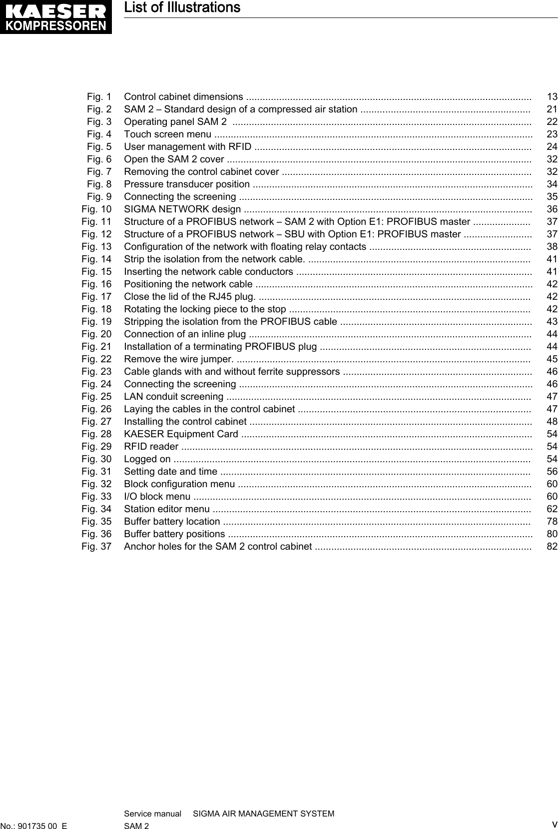
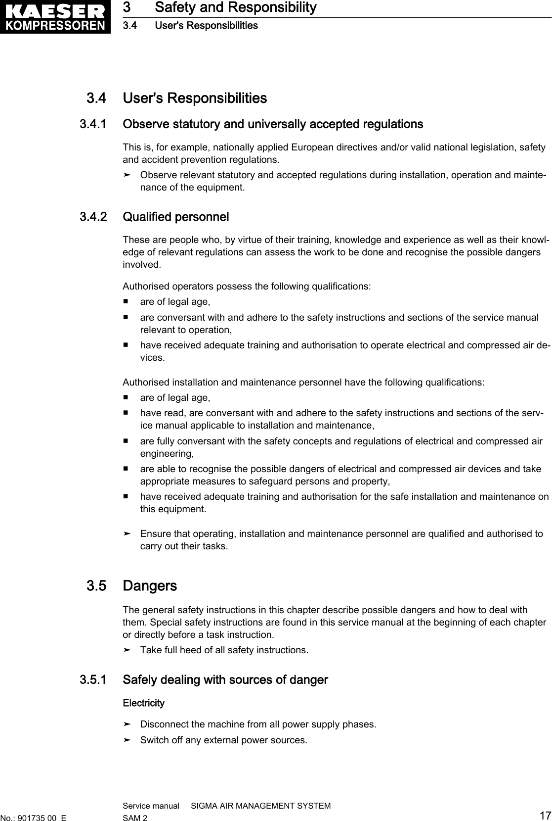
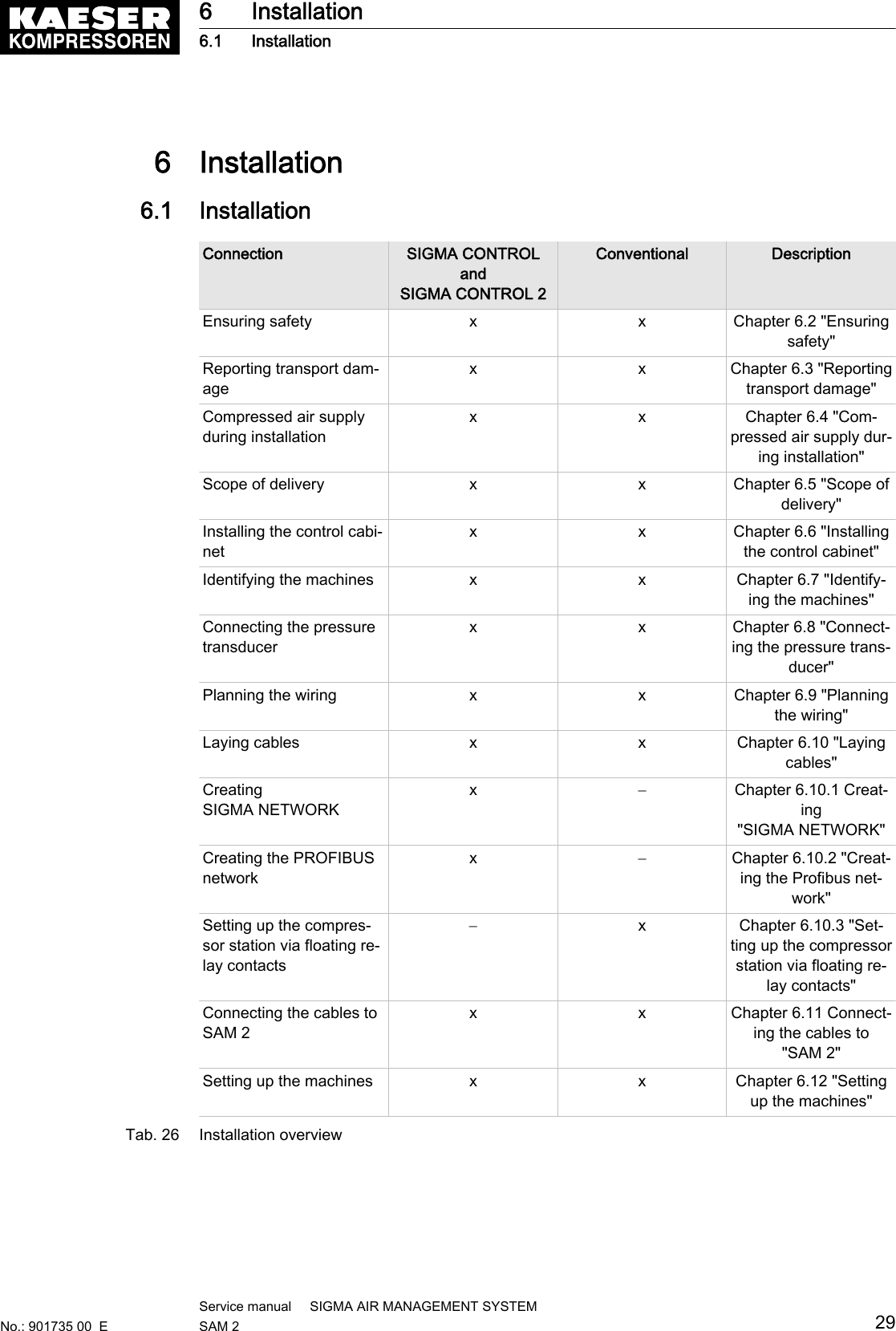
![Digital outputs (DOT) Module 6DOT – X20DO6322Insulation voltage between channel and bus[Veff]500Analogue Inputs (All) Module 4AlI – X20AO2632Measuring range [mA] 0-20Resolution [bit] 15Connection type Active and passive possible(2 conductor and 4 conductor technology)Ohmic resistance (internal) [Ohm] < 400Input protection Protection against supply voltage wiringMaximum error in 25 °C range from currentlymeasured value [%]0.08Maximum error in 25 °C offset from final value ofmeasuring range [%]0.02Distribution 24 VDC Module 6x 24 VDC - X20PD2113Nominal output voltage [V DC] 24, GroundOutput current, total [A] 6.0Fusing (internal, replaceable) [A], [mm] T6.3, 5x20Tab. 7 Technical data I/O-block and individual modules2.4.2 I/O Modules (only SBU)The following technical data apply to the individual I/O modules used only in SBU :Feature ValueConnection terminals Push-in terminalConnection diameter■Wire/single-core [mm2]■Flex/fine-core [mm2]■Wire end ferrule [mm2]■Double wire-end ferrule [mm2]Copper wires■ 0.08-2.5 / AWG 28-14■ 0.25-2.5 / AWG 24-14■ 0.25-1.5 / AWG 24-16■ 2x (0.25–0.75)Display elements Status LEDsTab. 8 Technical data, all I/O modules2.4.2.1 Module 4AIR – X20AT4222Feature ValueAnalogue inputs for PT100 IEC/EN 60751 4Range [ °C ] −200 – +850Resolution [Bit] 16Connection type Two-wire and three-wire technologyMeasuring current [µA] 2502 Technical Specifications2.4 Components within the control cabinet8Service manual SIGMA AIR MANAGEMENT SYSTEMSAM 2 No.: 901735 00 E](https://usermanual.wiki/Prodrive-Technologies/SAM2/User-Guide-2427703-Page-18.png)
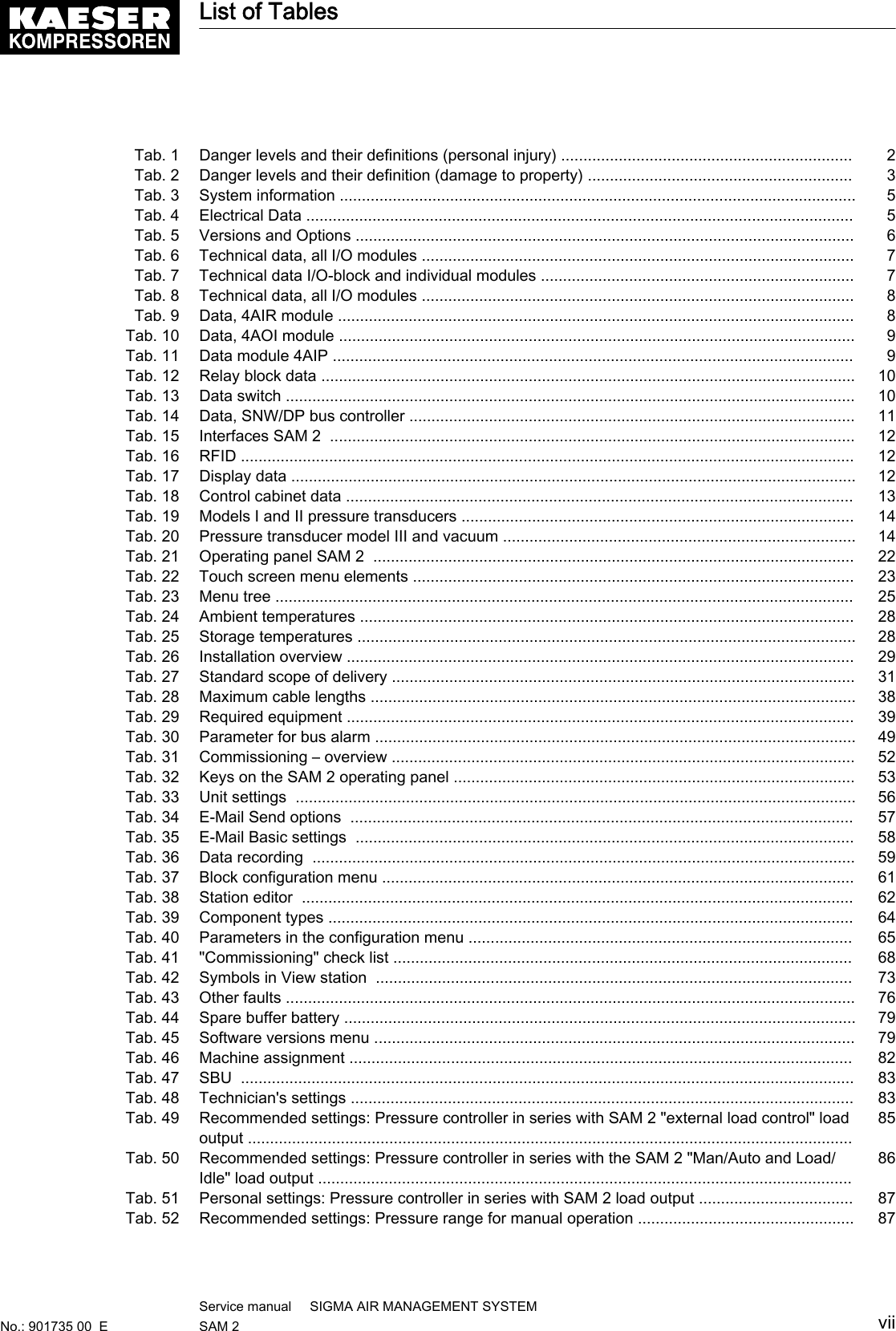
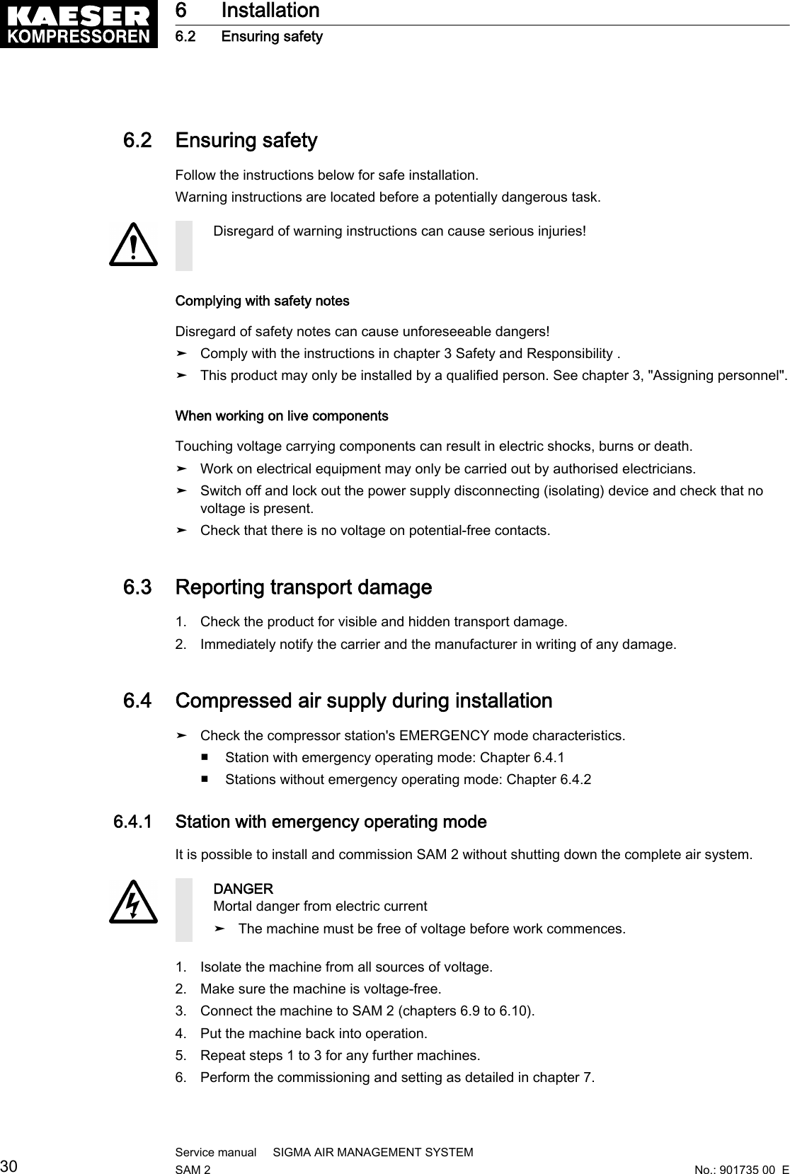
![Feature ValueMaximum error in 25 °C range from currentmeasured value [%]0.037Maximum error in 25 °C offset from final value ofmeasuring range [%]0.0015Isolation voltage input–internal bus [Veff] 500Tab. 9 Data, 4AIR module2.4.2.2 Module 4AOI – X20AO2632Feature ValueAnalogue outputs 0–20 mA 2Output range [mA] 0-20Resolution [bit] 15Max. ohmic resistance [Ohm] 500Output protection Short-circuit-proof, current-limiting 40 mAMaximum error in 25 °C range from currentmeasured value [%]0.045Maximum error in 25 °C offset from final value ofmeasuring range [%]0.025Isolation voltage output–internal bus [Veff] 500Tab. 10 Data, 4AOI module2.4.2.3 Module 4AIP – X20AP3121Feature ValueVoltage, analogue inputs■ Nominal voltage phase–phase max. [V AC],[Hz]■ Nominal voltage phase–N max. [V AC]■ Maximum overload voltage3■ 480 at 50/60■ 277■ 1.5xUN permanent, 2xUN for 1 minuteCurrent, analogue inputs■ Maximum overload current■ Resistance [mOhm]4■ 8xIN for 0.5s■ 500Measuring accuracy■ URMS and IRMS [%]■ Power [%]—■ < 0.5■ < 0.5Potential separation■ Inputs–internal bus■ Input–input—■ Yes■ No2 Technical Specifications2.4 Components within the control cabinetNo.: 901735 00 EService manual SIGMA AIR MANAGEMENT SYSTEMSAM 2 9](https://usermanual.wiki/Prodrive-Technologies/SAM2/User-Guide-2427703-Page-19.png)
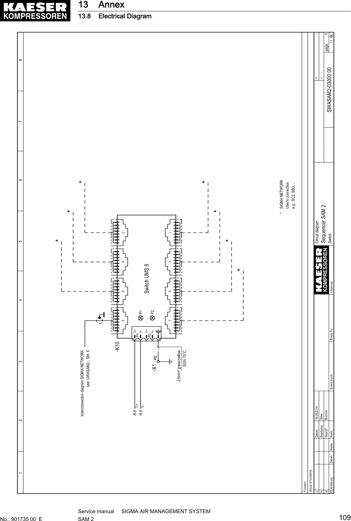
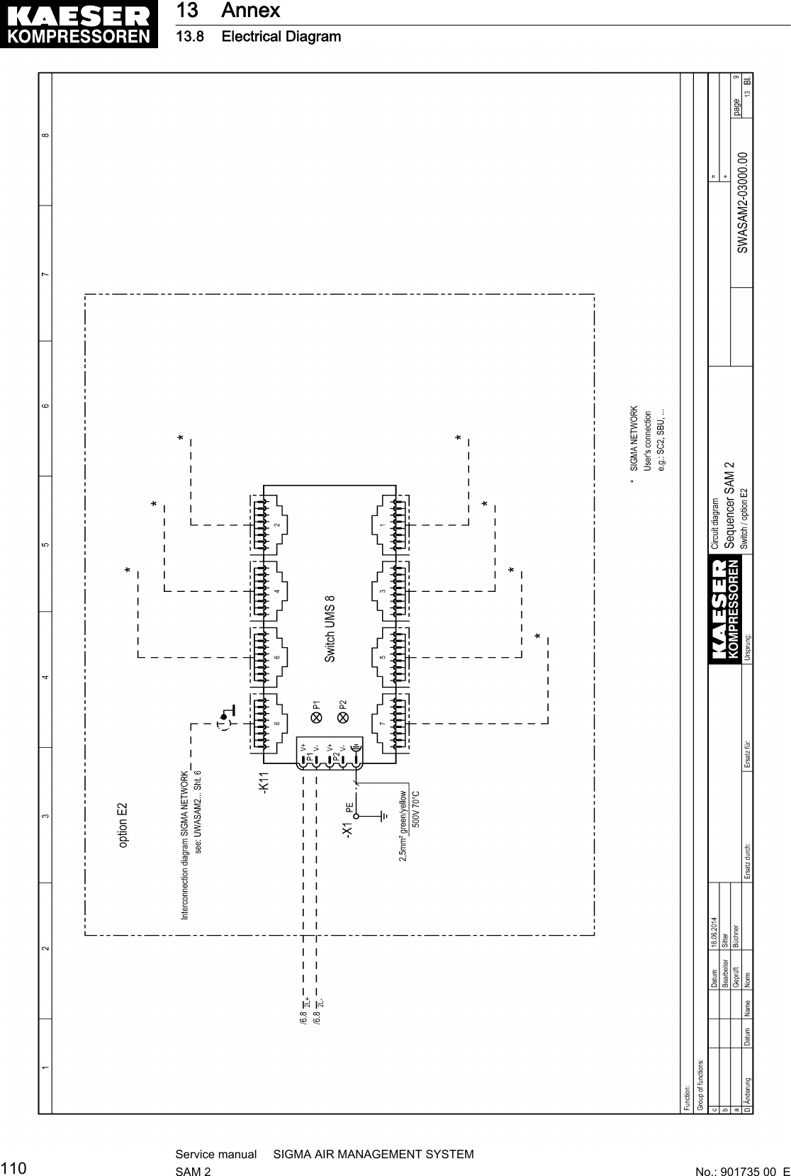
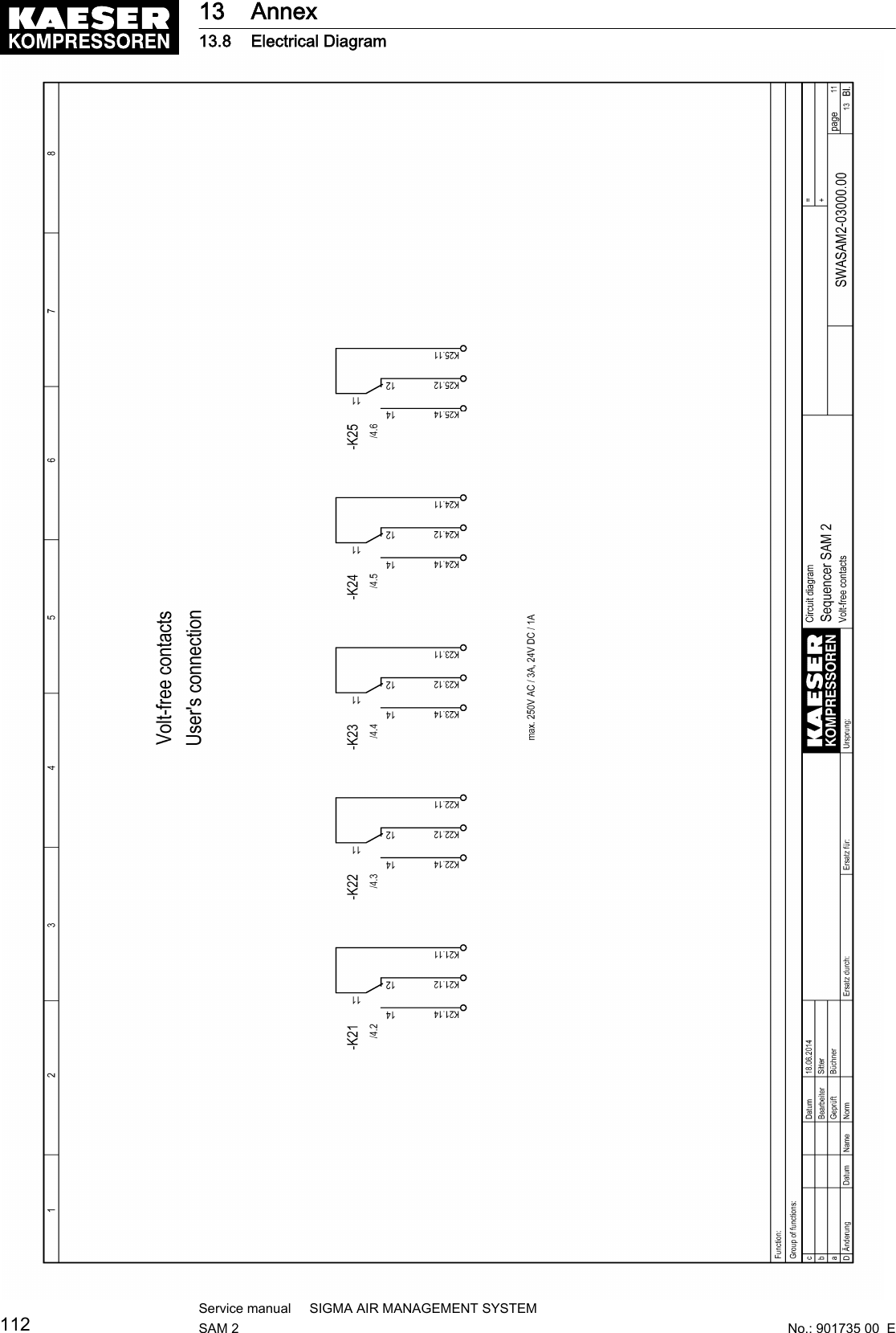
![Feature ValueIsolation voltage■ Inputs–Internal bus [V DC]■ Inputs–earth [V DC]—■ 5500■ 5500Tab. 11 Data module 4AIP2.4.3 Relay blockThe relay block comprises 5 relays ( SAM 2 ) or 6 relays ( SBU ) with the following technical data:Feature ValueConnection terminals Push-in terminalConnection diameter■Wire/single-core [mm2]■Flex/fine-core [mm2]■Wire end ferrule [mm2]■ Double wire-end ferruleCopper wires■ 0.14-1.5 / AWG 26-16■ 0.14-1.5 / AWG 26-16■ 0.14-1.5 / AWG 26-16■ not possibleStripping length [mm] 8Display elements Status LEDCoil voltage [V DC] 24Output contact■ Switching voltage [V]■ Min. switching current [mA] (at 12 V)■ Max. constant current [A]■ Switching capacity IEC 60947/DIN VDE066024 V DC13 [A]230 V AC15 [A]1 changeover contact■ 5 (at 100 mA) – 250 V AC/DC■ 10■ 6■ —13Inductive loads (e.g., auxiliary contact, solenoidvalve)to be connected with RC elementsRated isolation voltage [V AC] 250Tab. 12 Relay block data2.4.4 SIGMA NETWORK Switch 8 portFeature ValueKAESER SIGMA NETWORK ports 8Transfer rate [Mbps] 10/100Transfer mode Store-and-forward switching modeCharacteristics Auto crossing (Auto-MDI(X) ),Auto negotiation, Auto sensingConnections RJ45, 10/100Base-TXMax. conduit length between two components[m]1002 Technical Specifications2.4 Components within the control cabinet10Service manual SIGMA AIR MANAGEMENT SYSTEMSAM 2 No.: 901735 00 E](https://usermanual.wiki/Prodrive-Technologies/SAM2/User-Guide-2427703-Page-20.png)
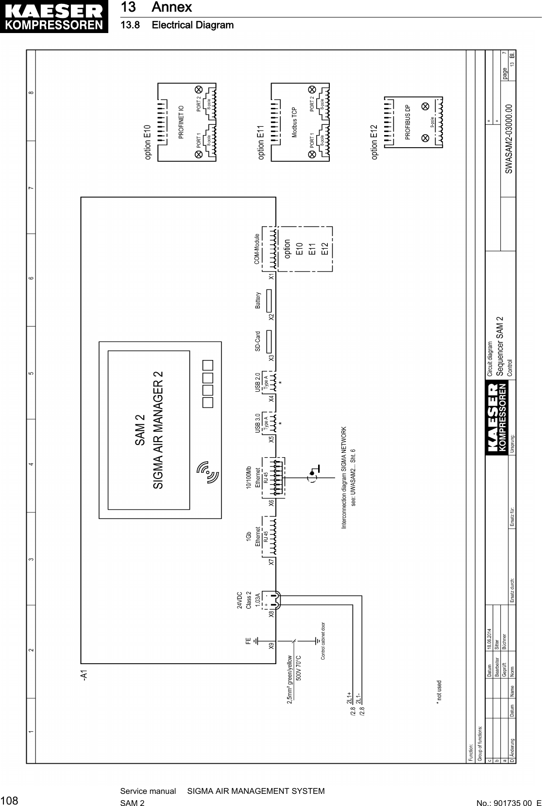
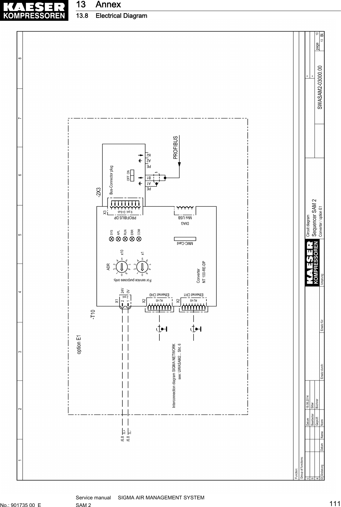
![Feature ValuePower supply [V DC] 9–48, @ 24 V DC/200 mADisplay elements Status LEDs for voltage and every portTab. 13 Data switch2.4.5 Protocol converter SIGMA NETWORK / PROFIBUS masterFeature ValueSIGMA NETWORK■ Transfer rate■ Properties 1■ Properties 2■ Max. conduit length between two compo‐nents [m]—■ 10/100 ■ Auto crossing■ Auto negotiation■ 100PROFIBUS DP■ Transfer rate [kBit/s]■ Interface■ Connections■ Max. conduit length for the entire bus length[m]Master■ 187.5■ RS486 floating■ 9-pole SUB-D socket■ 800Power supply [V DC] 24 +/-25 %, typ. @ 130 mADisplay elements Status LEDService interfaces Mini USB, slot for MMC memory card, rotaryswitchTab. 14 Data, SNW/DP bus controller2.4.6 SAM 2 -Terminal2.4.6.1 Industrial computer■ Industrial computer with Quad core processor■ 2 GB RAM■ 16 GB flash memory■ Buffer battery for real-time clock■ Voltage and temperature monitoring■ Update-capable with SD memory card2.4.6.2 InterfacesThe positions of the interfaces X1–X5 are marked on the rear of the SAM 2 terminal.2 Technical Specifications2.4 Components within the control cabinetNo.: 901735 00 EService manual SIGMA AIR MANAGEMENT SYSTEMSAM 2 11](https://usermanual.wiki/Prodrive-Technologies/SAM2/User-Guide-2427703-Page-21.png)
![Interface Connection MarkingCom modules 1) Slot for KAESER communicationmodulesX1Battery 2) For additional buffer battery X2SD card Slot for SD/SDHC/SDXC memorycardX3USB 2.0 1) For service purposes only X4USB 3.0 1) For service purposes only X5SIGMA NETWORK RJ485 socket (10/100Base T) X6Ethernet 1 Gb RJ485 socket (1000Base T) X724 V DC Power supply, protected againstpolarity reversalX8FE Equipotential bonding 6.3 mm flatplugX91) Slot/interface covered: Remove the cover if a communication module is installed.2) Slit covered: Remove the cover if an additional buffer battery is installed (see chapter 10.2).Tab. 15 Interfaces SAM 2Identification with RFID Equipment CardFeature ValueIntegrated hardware RFID write/read deviceHardware (external) KAESER Equipment CardRecognition in maximal distance [m] 0.05Frequency [MHz] 13.56Tab. 16 RFID2.4.6.3 DisplayFeature ValueDisplay model Colour display with touch screenDisplay resolution [px1)]1280 x 800Format 12,1”; 16:10Background lighting LEDModel LCD; industrial versionTouch operation CapacitiveSensor keys 41) px ≙ PixelTab. 17 Display data2 Technical Specifications2.4 Components within the control cabinet12Service manual SIGMA AIR MANAGEMENT SYSTEMSAM 2 No.: 901735 00 E](https://usermanual.wiki/Prodrive-Technologies/SAM2/User-Guide-2427703-Page-22.png)
![2.4.6.4 SoftwareSAM 2 terminal:■ Operating system: Linux■ KAESER controller software■ KAESER user interface2.5 Control cabinetTerminal and control cabinetFig. 1 Control cabinet dimensions1483 mm2540 mm3380 mm480 mm5284 mmModel SAM 2-4 SAM 2-8 SAM 2-16Material Enclosure: Sheet metal, painted RAL 9007 greyCover: Plastic, RAL 7016, anthracite greyMass [kg] 15Enclosure protection IP54Tab. 18 Control cabinet data2 Technical Specifications2.5 Control cabinetNo.: 901735 00 EService manual SIGMA AIR MANAGEMENT SYSTEMSAM 2 13](https://usermanual.wiki/Prodrive-Technologies/SAM2/User-Guide-2427703-Page-23.png)
![2.6 Pressure transducerModels I and II pressure transducersModel I IIMeasurement range [bar] 0-1 0–6/10/16/20/32/45Overload limit [bar] 3.5 double final pressureDeviation of characteristic from final valueLimit setting [%]≤ 0.5 ≤ 0.5 (0.25 typical)Air connection, male thread G 1/2 B DIN 16288Stainless steelG 1/4 A DIN 3852Stainless steelViton sealsNominal temperature range [ °C ] –20...+80 –25...+85Nominal temperature range [K] 253-353 248-358Fluid temperature range [ °C ] –30...+100 –40...+100Fluid temperature range [K] 243-373 233-373Storage temperature range [ °C ] –40...+100 –40...+100Storage temperature range [K] 233-373 233-373Temperature influence / 10 K over the range [%] ± 0.2 ± 0.15Temperature influence / 10 K over the range [%] ± 0.2 ± 0.15Output signal (two-wire technique) [mA] 4-20 4-20Power supply connection(plug to EN 175301-803)PG 11 PG 9Enclosure Stainless steel Stainless steelEnclosure protection IP 65 IP 65Tightening torque [Nm] 17-20 17-20Tab. 19 Models I and II pressure transducersPressure transducer model III and vacuumModel III Vacuum pumpMeasurement range [bar] 0-16 –Measurement range, absolute [bar] – 0-1Overload limit [bar] 32 3Deviation of characteristic from final valueLimit setting [%]≤ 1 (0.5 typical) ≤ 1 (0.5 typical)Air connection, male thread G 1/2 A G 1/2 AAir connection, male thread G 1/8 A G 1/8 ARated temperature range [ °C ] –25...+85 –25...+85Rated temperature range [K] 248-358 248-358Fluid temperature range [ °C ] –30...+125 –30...+125Fluid temperature range [K] 243-373 243-373Storage temperature range [ °C ] –50...+100 –50...+1002 Technical Specifications2.6 Pressure transducer14Service manual SIGMA AIR MANAGEMENT SYSTEMSAM 2 No.: 901735 00 E](https://usermanual.wiki/Prodrive-Technologies/SAM2/User-Guide-2427703-Page-24.png)
![Model III Vacuum pumpStorage temperature range [K] 233-373 233-373Temperature influence / 10 K over the range [%] ± 0.4 ± 0.4Temperature influence / 10 K over the range [%] ± 0.4 ± 0.4Output signal (two-wire technique) [mA] 4-20 4-20Power supply connection(plug to EN 175301-803)PG 9 PG 9Enclosure brass brassEnclosure protection IP 65 IP 65Tightening torque [Nm] 17-20 17-20Tab. 20 Pressure transducer model III and vacuum2 Technical Specifications2.6 Pressure transducerNo.: 901735 00 EService manual SIGMA AIR MANAGEMENT SYSTEMSAM 2 15](https://usermanual.wiki/Prodrive-Technologies/SAM2/User-Guide-2427703-Page-25.png)

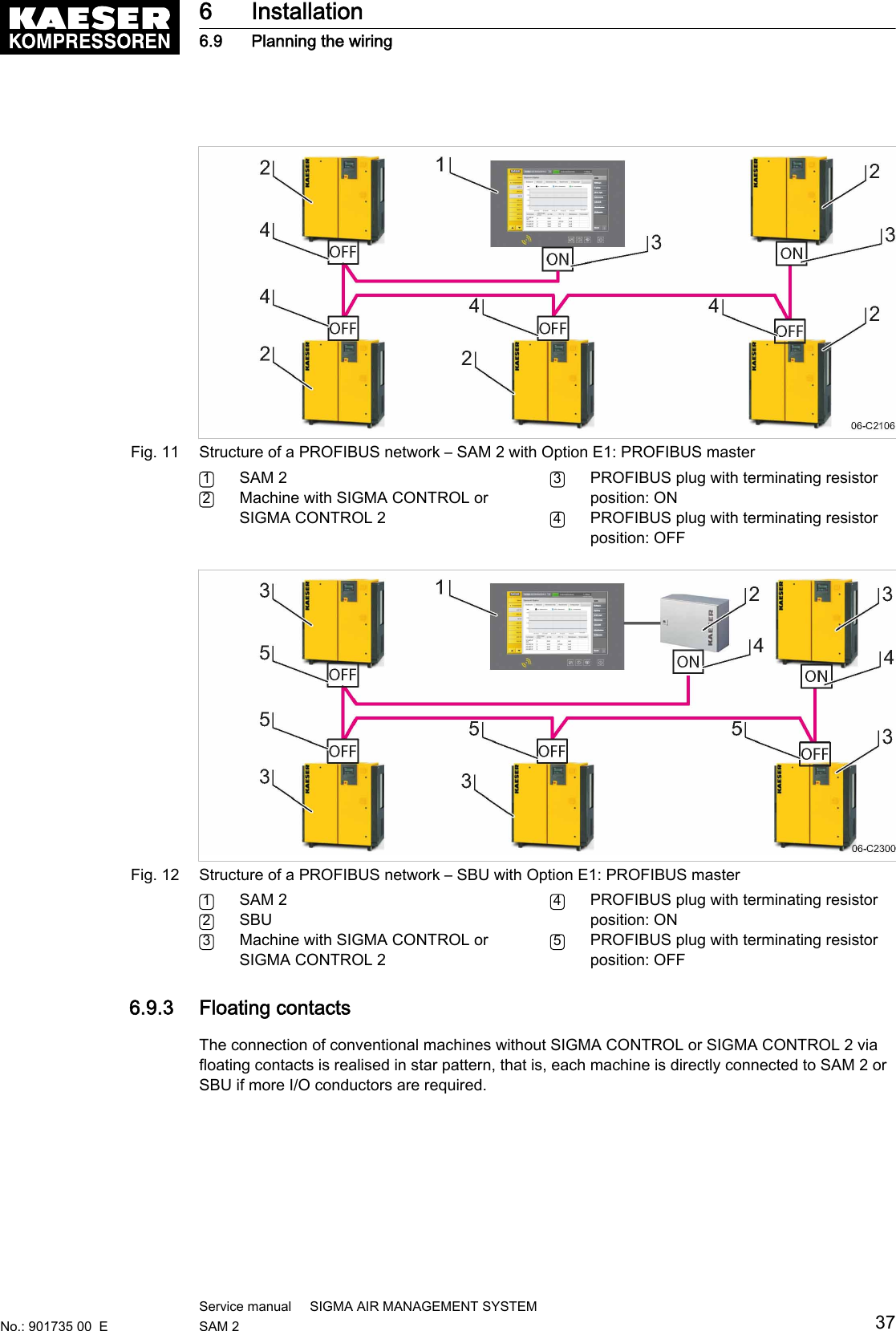
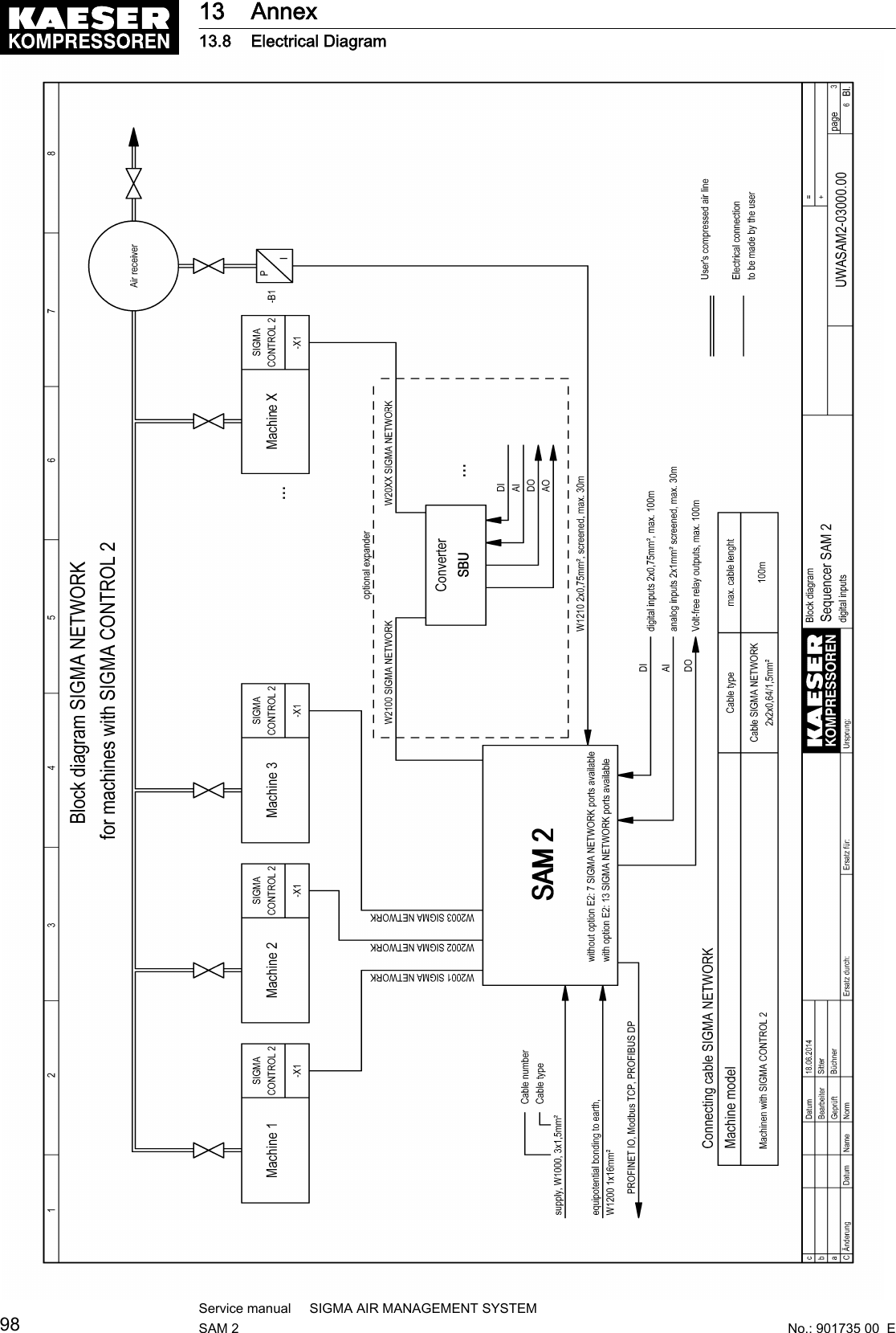
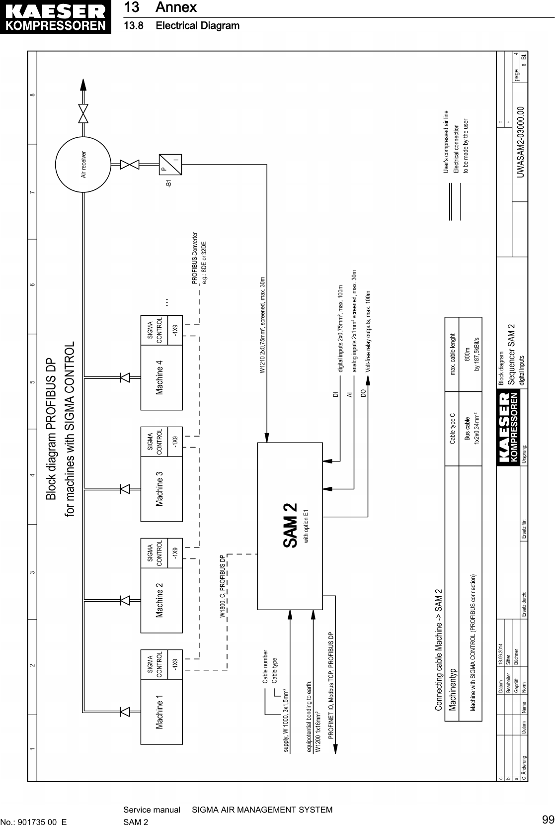
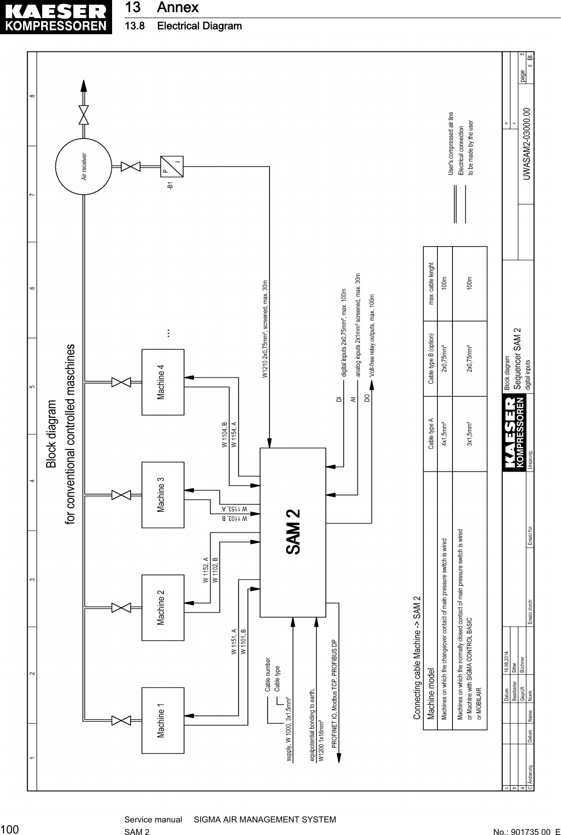
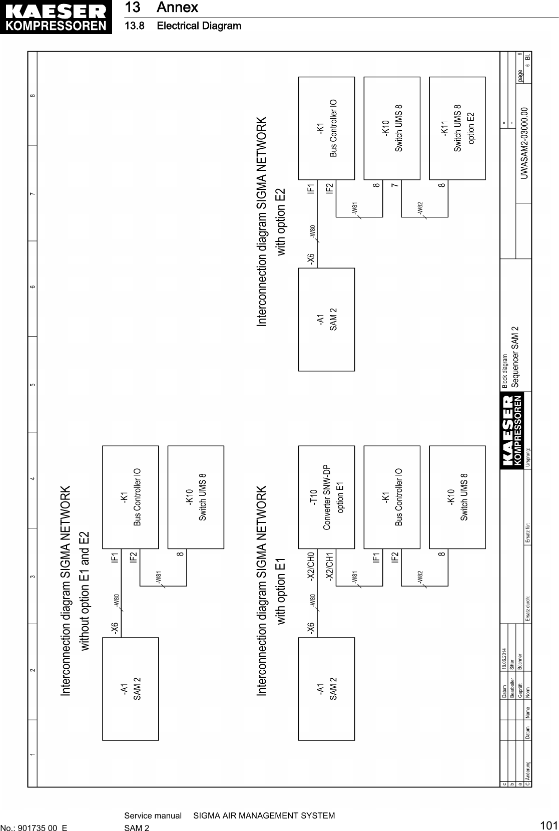
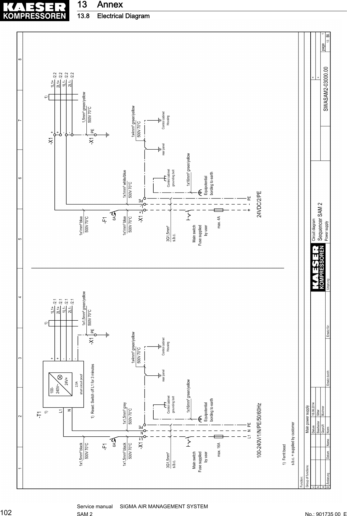
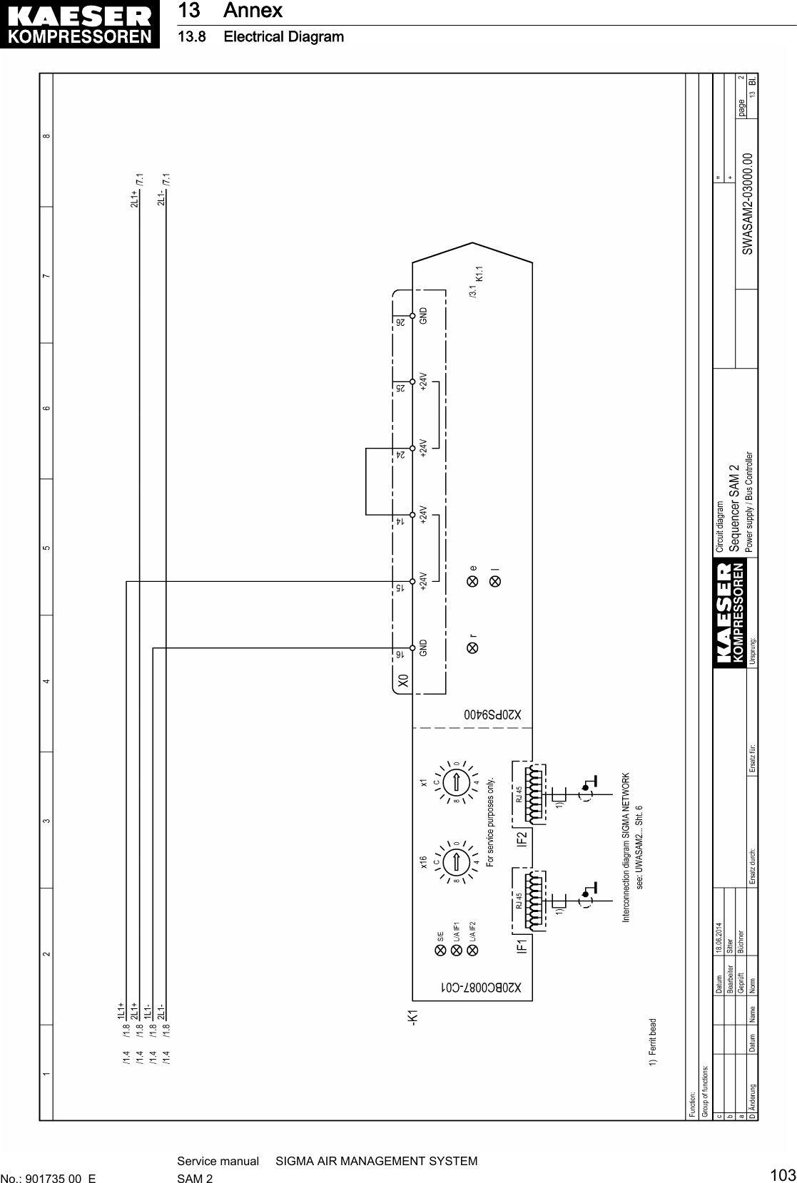
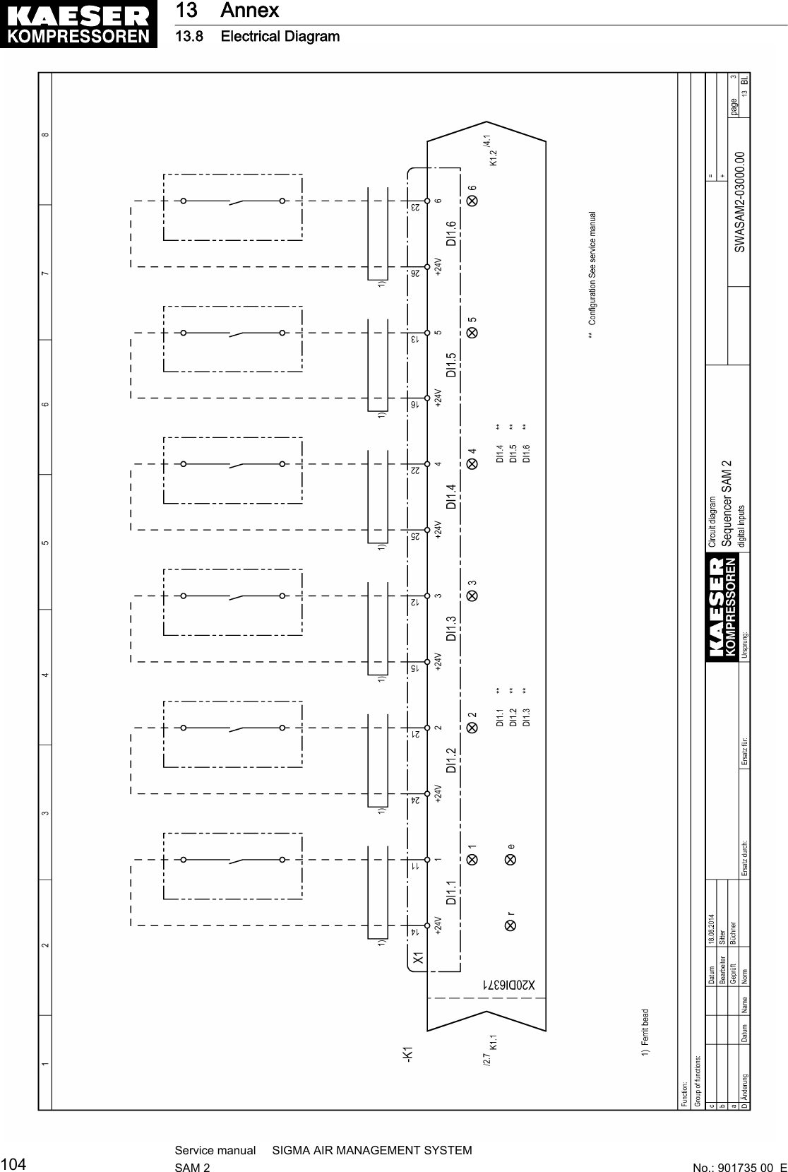
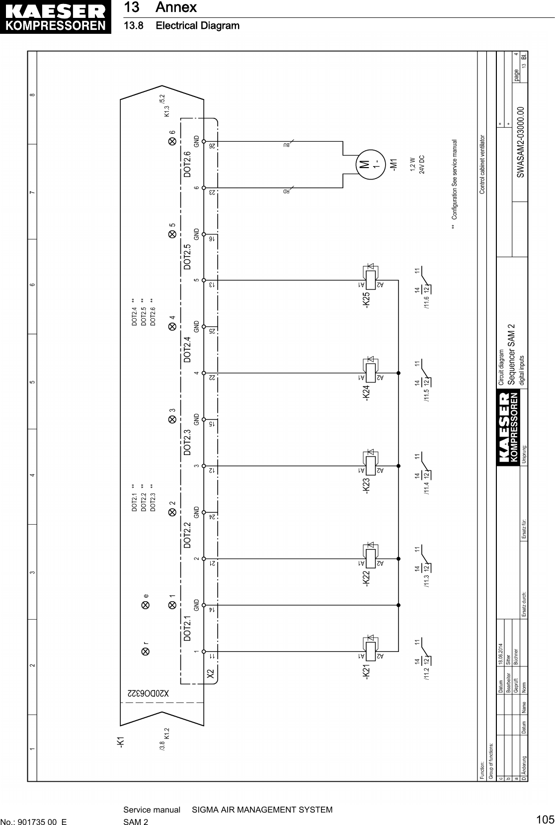
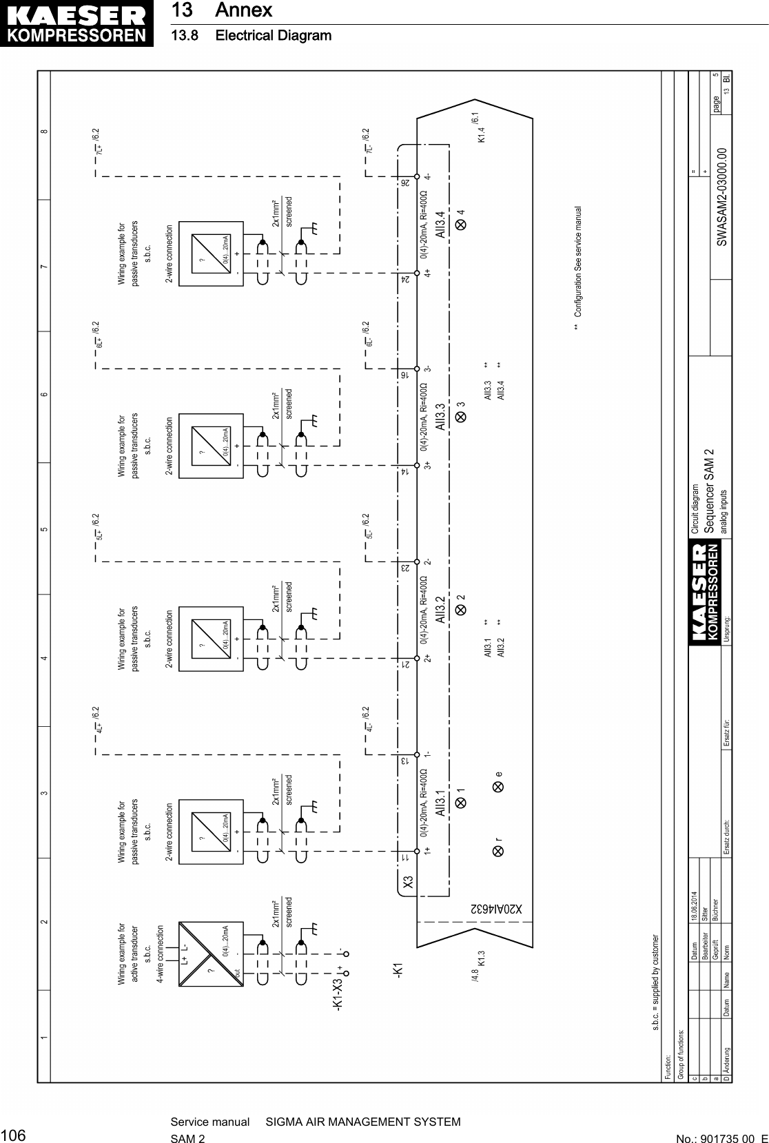
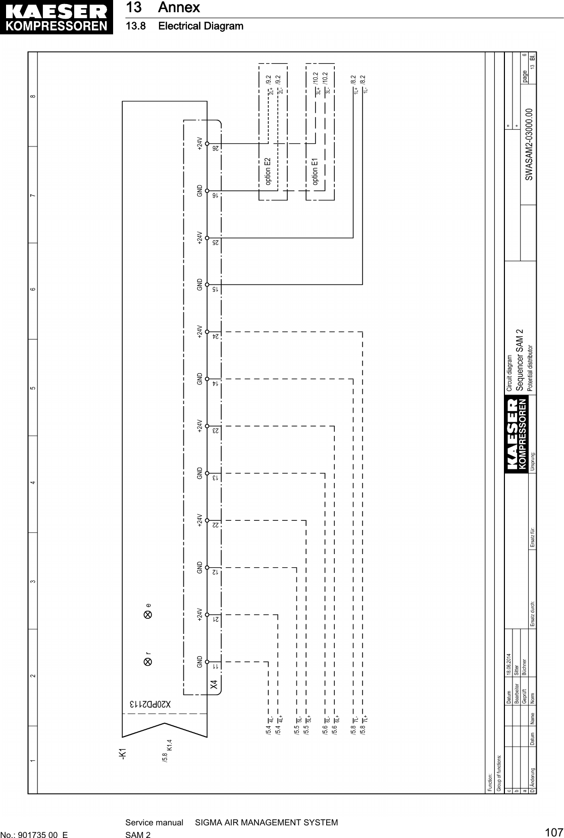
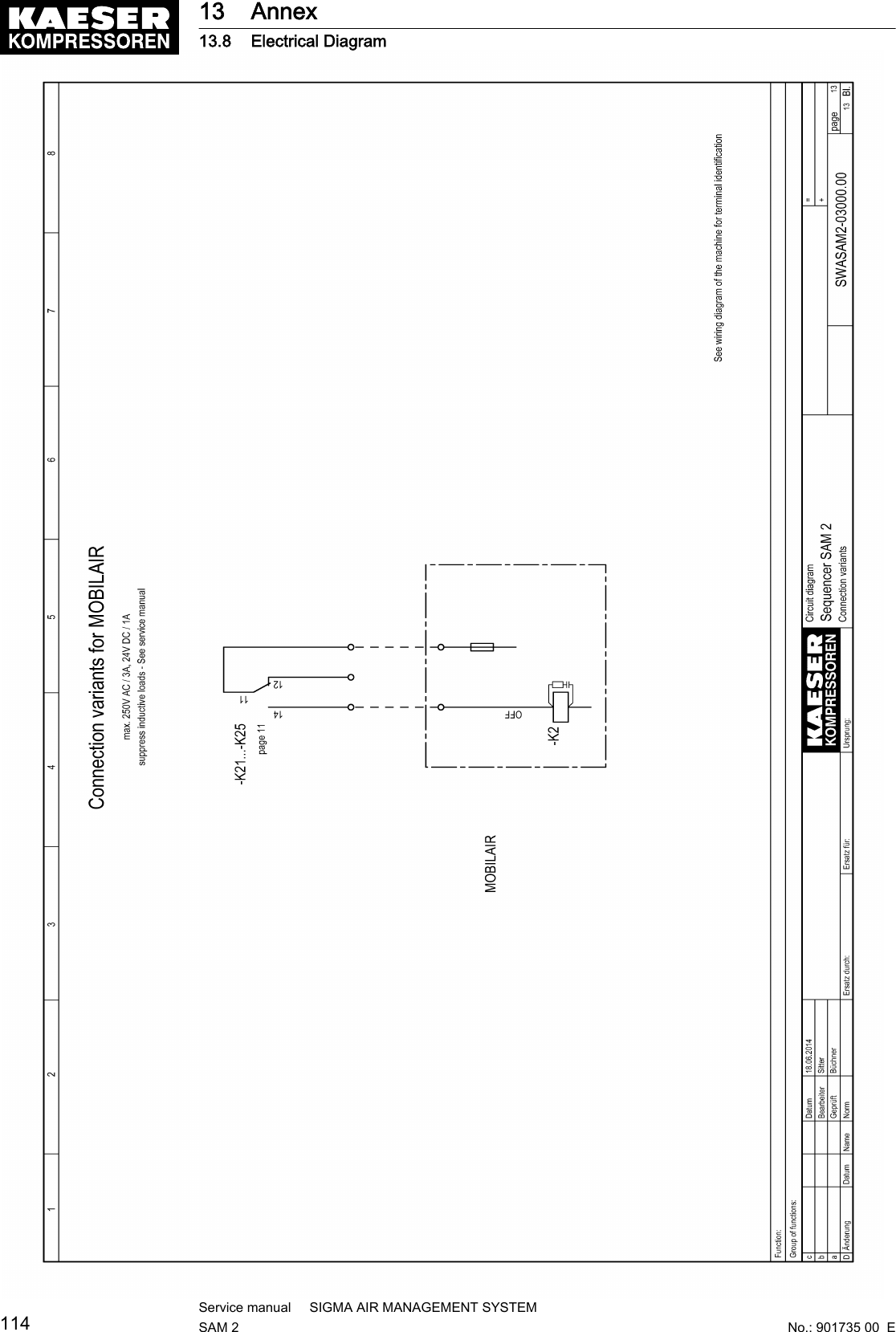
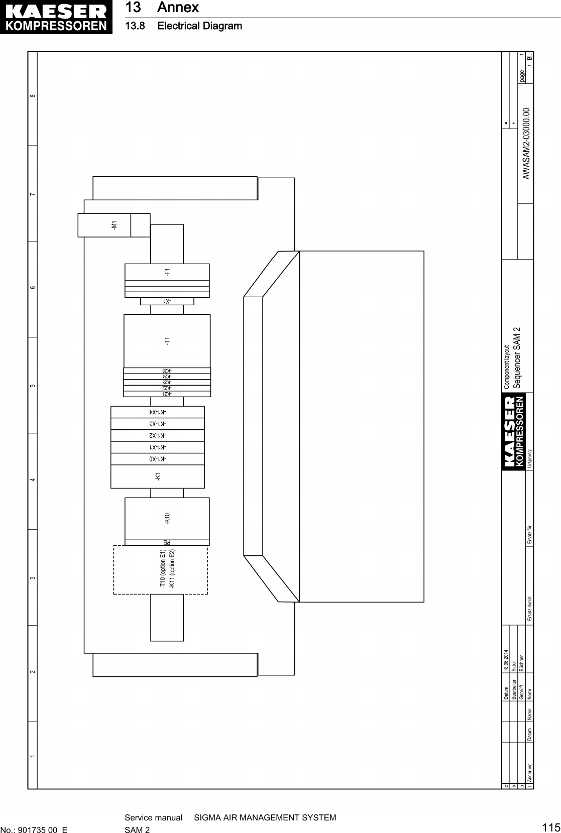
![Fig. 13 Configuration of the network with floating relay contacts1SAM 22SBU3Machine with SIGMA CONTROL orSIGMA CONTROL 24Machine connected via floating relay con‐tacts6.9.4 Instructions on the electrical installation■ A supply disconnecting device to EN 60204 must be installed by the user.■ Do not exceed the following maximal values for the cable lengths:Model Maximum cable length [m] RemarkSIGMA NETWORK 100 Maximum cable length betweentwo SIGMA NETWORK compo‐nents.Digital transistor outputs 30Digital relay outputs 100Digital inputs 30Analogue inputs 30 screenedPROFIBUS 800 Maximum cable length of the en‐tire PROFIBUS.Tab. 28 Maximum cable lengths■ Use galvanic isolation on cables laid outside the building to ensure increased lightning protec‐tion (preferably fibre optic cable).■ See chapter 2 for conductor types and cross-sections and the wiring diagram in chapter 13.8for cable selection. We recommend to use flexible stranded wires wherever possible.■ This suppressor is suitable for inductive loads connected to the relay outputs.6.9.5 Prerequisites and accessories required for connection withSIGMA NETWORKPrerequisites: For each SIGMA NETWORK device ( SIGMA CONTROL 2 machine, SBU ) aSIGMA NETWORK port is provided.6 Installation6.9 Planning the wiring38Service manual SIGMA AIR MANAGEMENT SYSTEMSAM 2 No.: 901735 00 E](https://usermanual.wiki/Prodrive-Technologies/SAM2/User-Guide-2427703-Page-48.png)
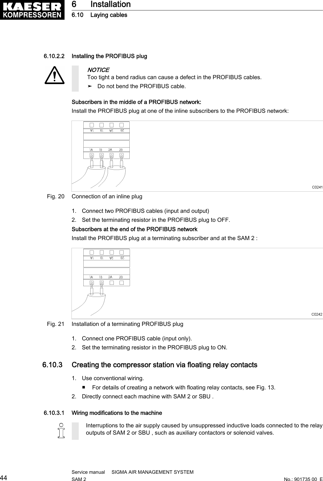
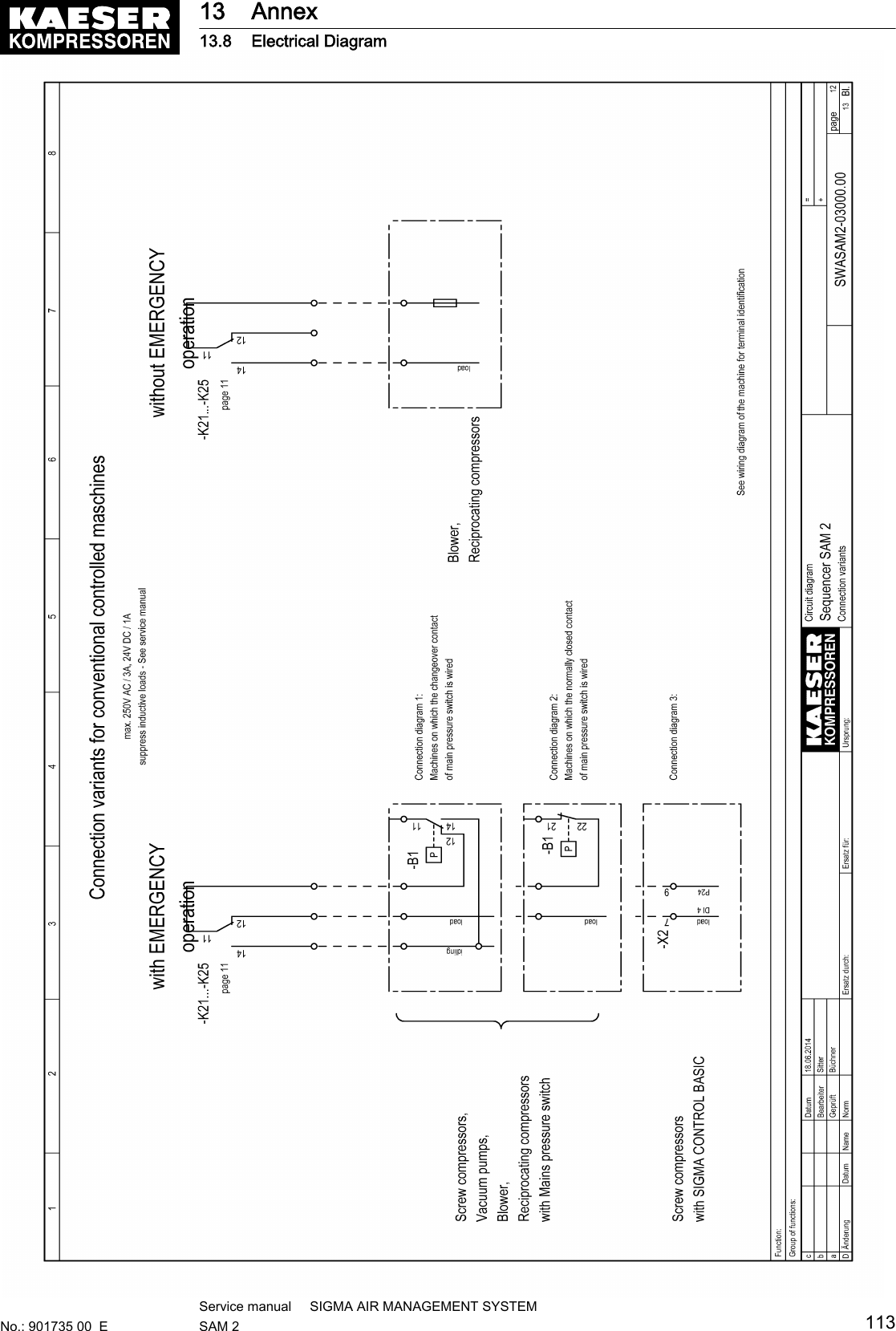
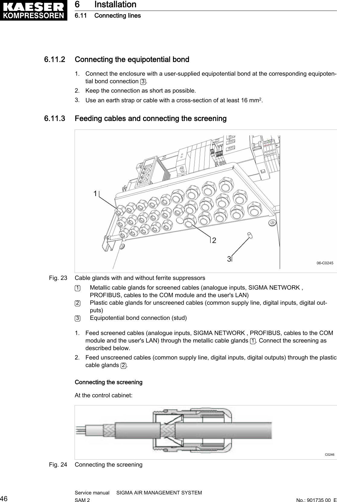
![1. Suppress inductive loads with an RC interference suppressor.2. Connect the interference suppressor in parallel directly at the coil (connections A1–A2). If theconnections are inaccessible, in solenoid valves for example, the suppressor can also be con‐nected to the corresponding terminals on the terminal strip.3. Use an RC interference suppressor suited to the coil voltage and apparent holding power, seechapter 13.6.Machine with "external load signal" control inputKAESER machines from 1990 onwards with terminal 32W:Fig. 22 Remove the wire jumper.➤ Remove the jumper between the terminals (terminals 32W and 21 or 18) to allow sequencing.Machines without terminal 32W1. Fit terminal 32W in the terminal strip.2. Disconnect the conductor A of the mains pressure switch cable connected to terminal 18.3. Disconnect the conductor A of the mains pressure switch cable connected to terminal 21.4. Connect the conductor A to terminal 32W.6.10.3.2 Machine with one control input for "Operating mode Manual/Automatic" / LOAD/IDLEKAESER machines from1990 onwards:If a jumper is connected between the terminals for manual operation [-X1 (W) 20 or 17 and -X1 (W) 24 (W)] on the terminal strip for connection of SAM 2 or SBU , then it must be removed. Amore precise designation of the terminals is given in the electrical diagrams for the machine.➤ Remove wire jumper if necessary.6.11 Connecting lines6.11.1 Wiring the control cabinetPrecondition The control cabinet is properly attached to the wall as described in chapter 6.6.The base plate is freely accessible.➤ Wire the control cabinet as described below.6 Installation6.11 Connecting linesNo.: 901735 00 EService manual SIGMA AIR MANAGEMENT SYSTEMSAM 2 45](https://usermanual.wiki/Prodrive-Technologies/SAM2/User-Guide-2427703-Page-55.png)
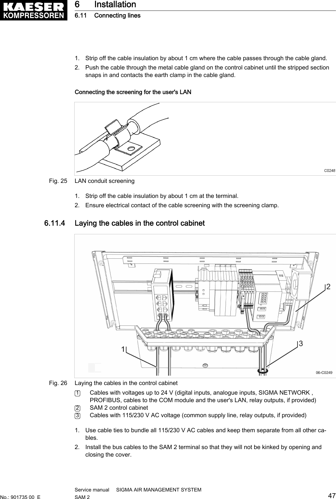
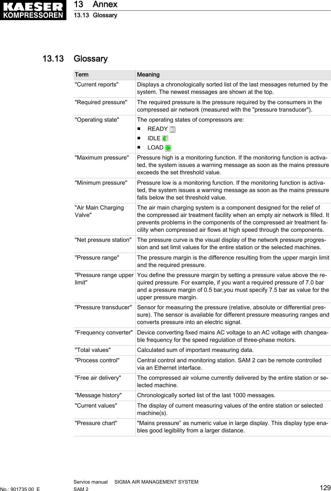
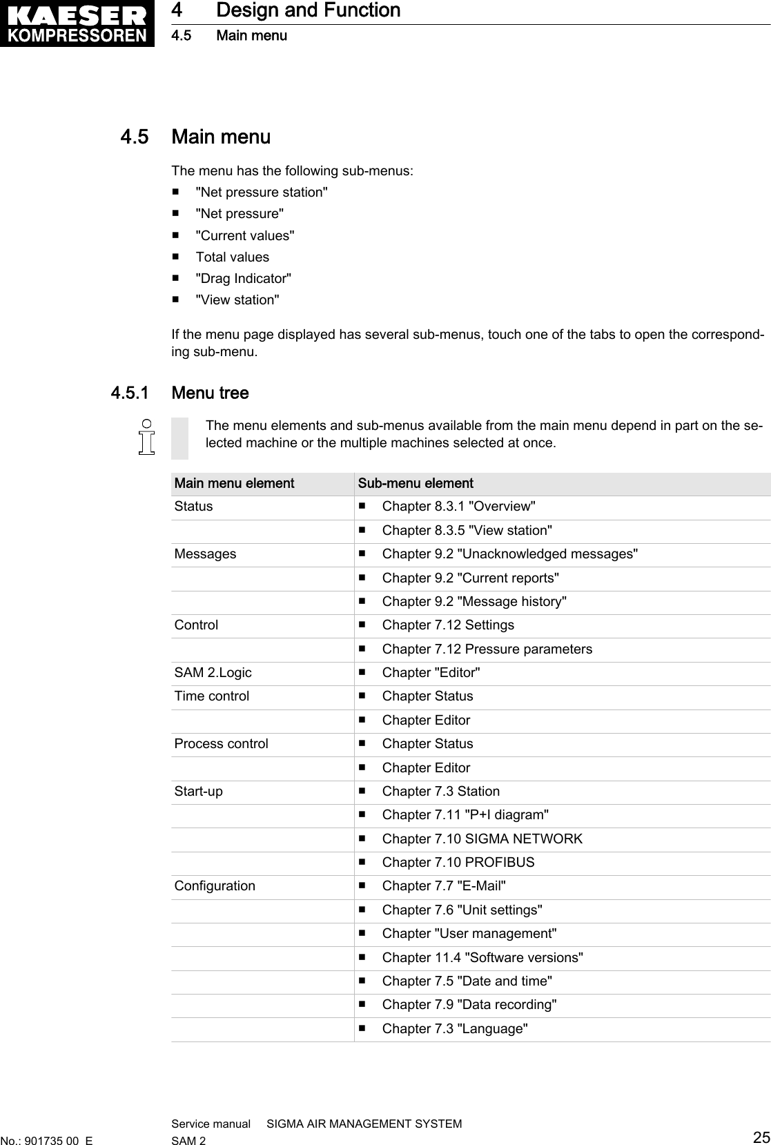
![2. If the menu page displayed has several sub-menus, touch one of the tabs to open the corre‐sponding sub-menu.3. Enter the required parameters in the corresponding fields.4. If necessary, activate the desired functions by touching the selection box.7.12.1 Setting the ParameterThe fundamental pressure values of the station must be set in the Parameter menu.7.12.1.1 Pressure range upper limit [pR]You define the pressure margin by setting a pressure value above the required pressure.For example, if you want a required pressure of 7.0 bar and a pressure margin of 0.5 bar,you mustspecify 7.5 bar as value for the upper pressure margin.7.12.1.2 Pressure rangeThe pressure margin is the difference resulting from the upper margin limit and the required pres‐sure.For energetic reasons, select the largest possible pressure margin. Practical values are 0.8–1.2bar, for example. Lower values for the pressure margin result in more frequent machine motorstarts.7.12.1.3 Required pressure [pREQ]The required pressure is the pressure required by the consumers in the compressed air network(measured with the "pressure transducer").SAM 2 usually maintains the required pressure with a maximum deviation of 0.1 bar. For energeticreasons, the operating pressure is to be set as low as possible, i.e., not higher as required for theconsumers within the compressed air network. A pressure of 1 bar higher than required causes ap‐proximately 6 % more energy consumption.7.12.1.4 Maximum pressurePressure high [ph] is a monitoring function. If the monitoring function is activated, the system is‐sues a warning message as soon as the mains pressure exceeds the set threshold value for theset time.7.12.1.5 Minimum pressurePressure low [pt] is a monitoring function. If the monitoring function is activated, the system issuesa warning message as soon as the mains pressure falls below the set threshold value for the settime.The monitoring function is provided in two variants:■ Δpt: This monitoring function uses a pressure limit relative to the set required pressure.■ pt: This monitoring function uses a pressure limit which is independent of the required pres‐sure.You cannot use both variants at the same time.7 Initial Start-up7.12 ControlNo.: 901735 00 EService manual SIGMA AIR MANAGEMENT SYSTEMSAM 2 67](https://usermanual.wiki/Prodrive-Technologies/SAM2/User-Guide-2427703-Page-77.png)
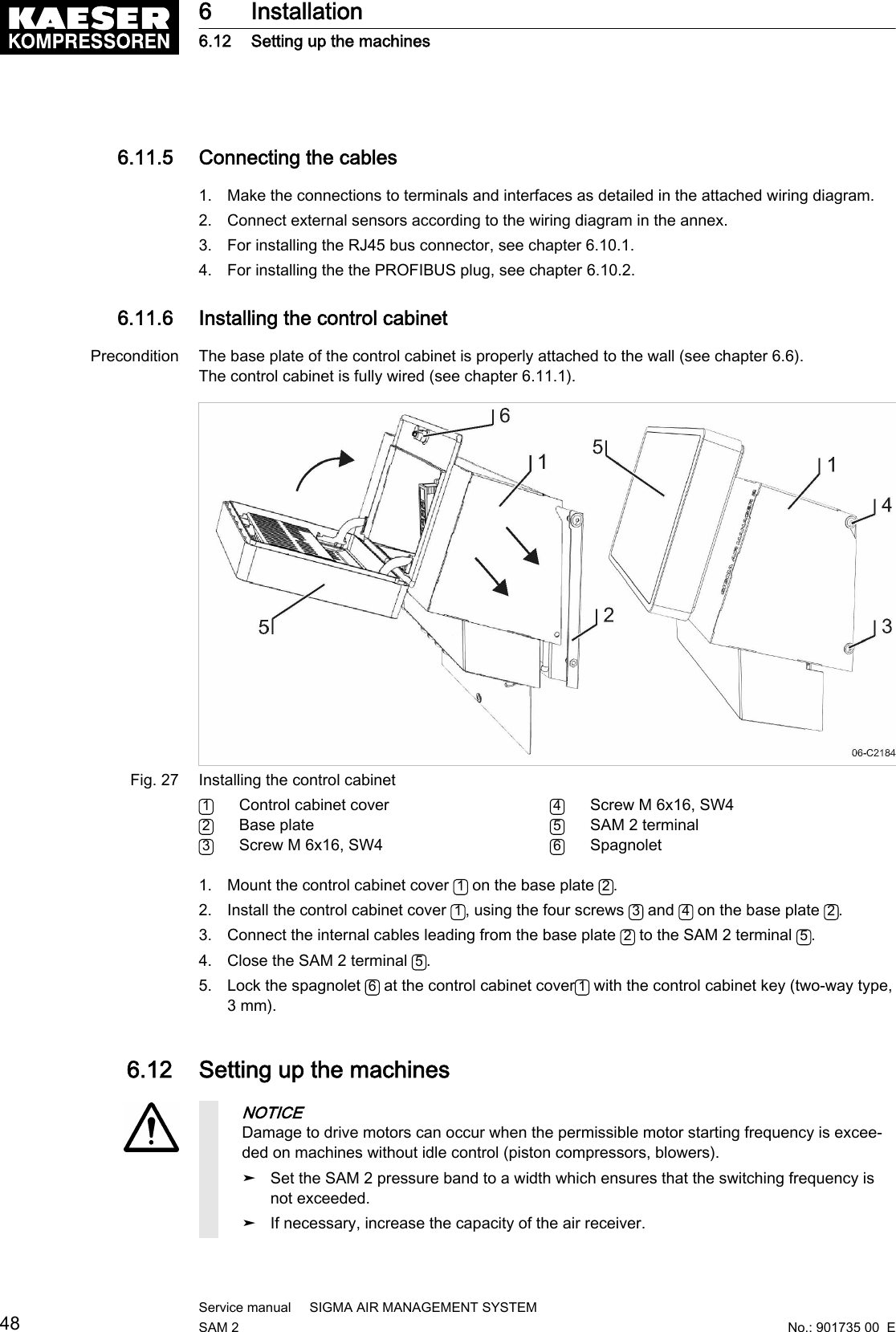
![■ Current values■ Total values■ Drag Indicator■ View station1. Press Status ➙ Overview or Status ➙ View station .2. If the menu page displayed has several sub-menus, touch one of the tabs to open the corre‐sponding sub-menu.8.3.1 Net pressure stationThe pressure curve is the visual display of the network pressure progression and set limit valuesfor the entire station or the selected machines.One or more pressure transducers in the network provide the measured values. " " If multiple pres‐sure transducers are used, the software calculates a weighted mean value.The values are displayed in the previously set units for the set time axis.8.3.1.1 Net pressure [pN]The system displays the progression curve of the network pressure over the time axis.The values are displayed in the set unit.8.3.1.2 Required pressure [pREQ]The required pressure is the pressure required by the consumers in the compressed air network(measured with the "pressure transducer").SAM 2 usually maintains the required pressure with a maximum deviation of 0.1 bar. For energeticreasons, the operating pressure is to be set as low as possible, i.e., not higher as required for theconsumers within the compressed air network. A pressure of 1 bar higher than required causes ap‐proximately 6 % more energy consumption.8.3.1.3 Pressure rangeThe pressure margin is the difference resulting from the upper margin limit and the required pres‐sure.For energetic reasons, select the largest possible pressure margin. Practical values are 0.8–1.2bar, for example. Lower values for the pressure margin result in more frequent machine motorstarts.8.3.1.4 CompressorThe machine's name within the station. This name can be set in the P&I diagram menu.8.3.1.5 Free air deliveryCurrent compressed air volume delivered by the machine.The values are displayed in the set unit.8.3.1.6 PiCurrent compressed air volume generated by the machine.8 Operation8.3 Main menuNo.: 901735 00 EService manual SIGMA AIR MANAGEMENT SYSTEMSAM 2 71](https://usermanual.wiki/Prodrive-Technologies/SAM2/User-Guide-2427703-Page-81.png)
![11 Spares, Operating Materials, Service11.1 Note the nameplateThe nameplate contains all information to identify your machine. This information is essential to usin order to provide you with optimal service.➤ Please give the information from the nameplate with every enquiry and order for spares.11.2 Spare partsName Voltage[V]Capacity[Ah]ModelLithium buffer battery 3.0 0.19 CR2032/BR2032Tab. 44 Spare buffer battery11.3 KAESER AIR SERVICEKAESER AIR SERVICE offers:■ Authorised service technicians with KAESER factory training■ Increased operational reliability ensured by preventive maintenance■ Energy savings achieved by avoidance of pressure losses■ optimum conditions for operation of the compressed air system,■ The security of genuine KAESER spares.■ Increased legal certainty as all regulations are kept to.➤ It make sense to sign a KAESER AIR SERVICE maintenance agreement.Your advantage:lower costs and higher compressed air availability.11.4 Displaying the software versionYou can display the versions of the various software modules in SAM 2 .➤ Press Configuration ➙ Software versions .The Software versions menu is displayed.Parameter MeaningSoftware Software name SAM 2Tab. 45 Software versions menu11 Spares, Operating Materials, Service11.1 Note the nameplateNo.: 901735 00 EService manual SIGMA AIR MANAGEMENT SYSTEMSAM 2 79](https://usermanual.wiki/Prodrive-Technologies/SAM2/User-Guide-2427703-Page-89.png)
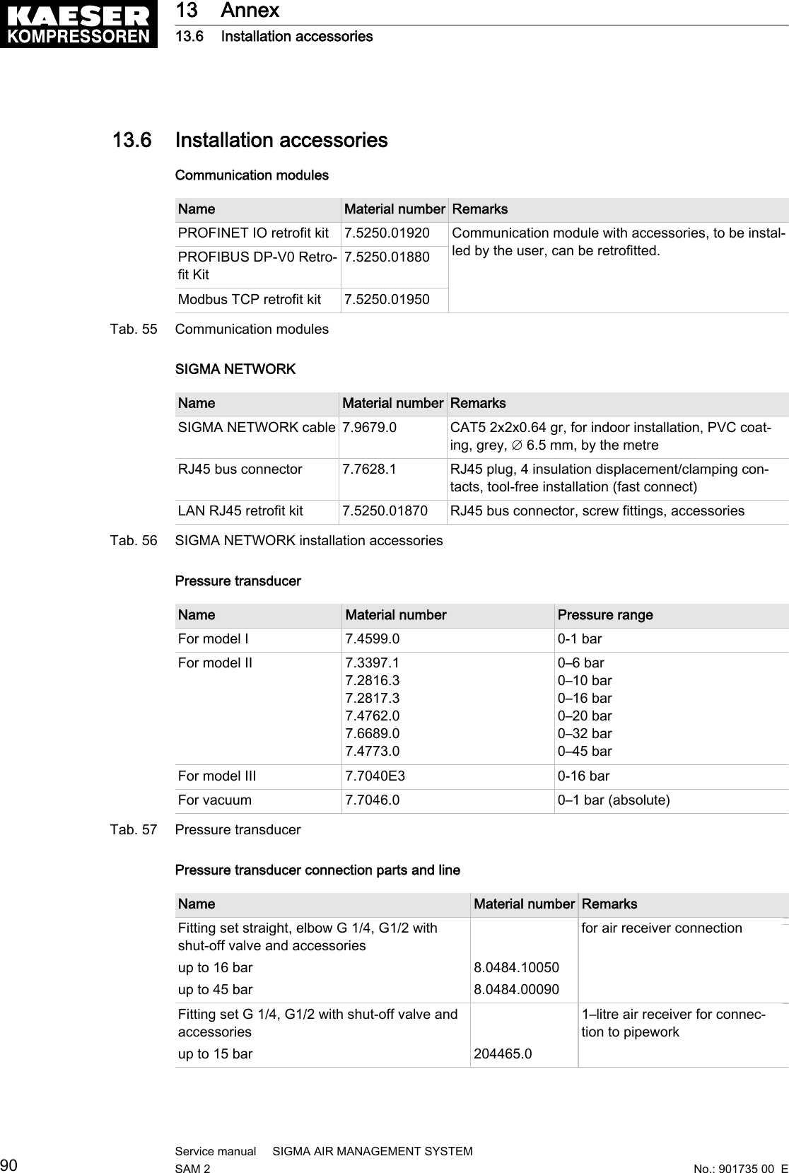
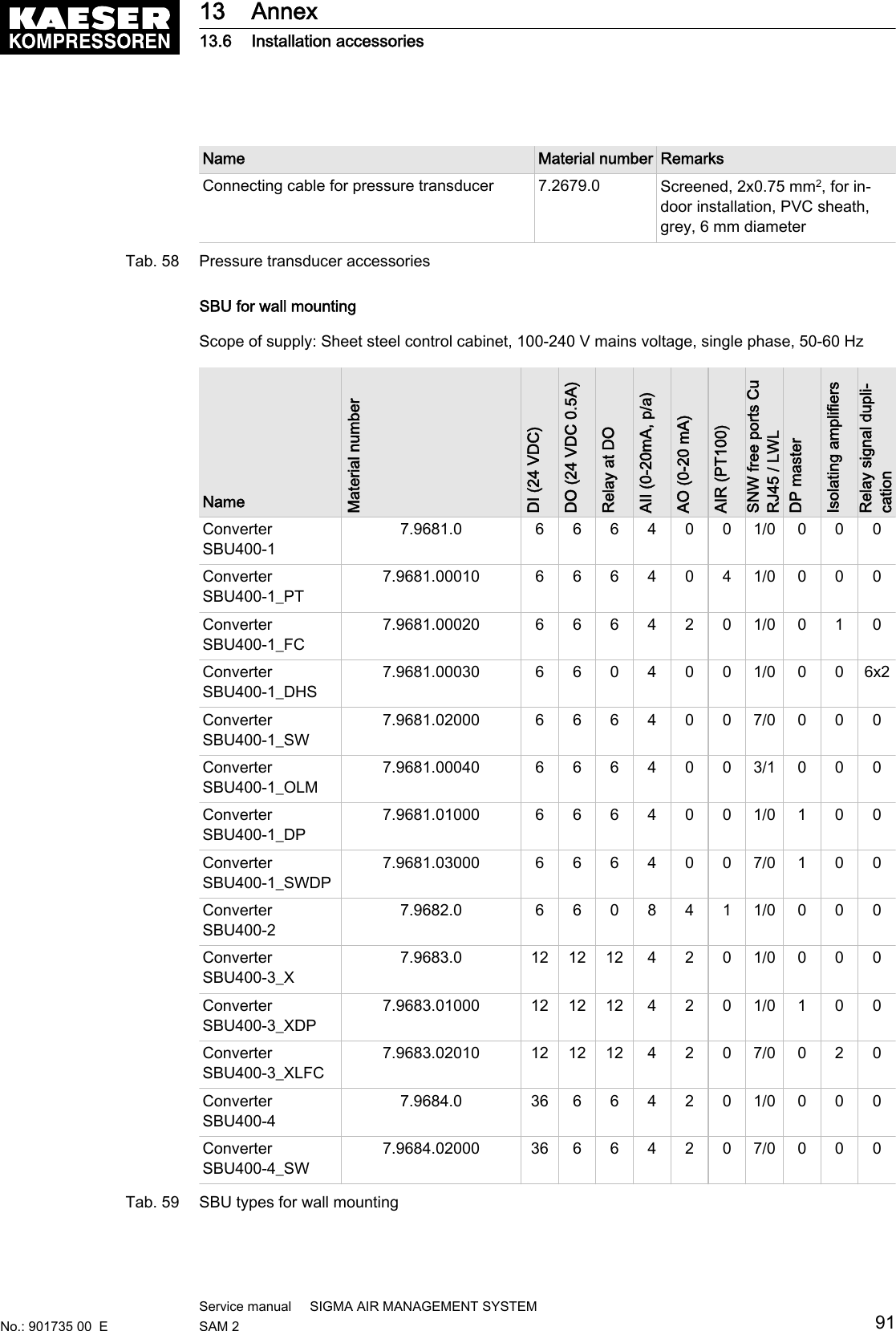
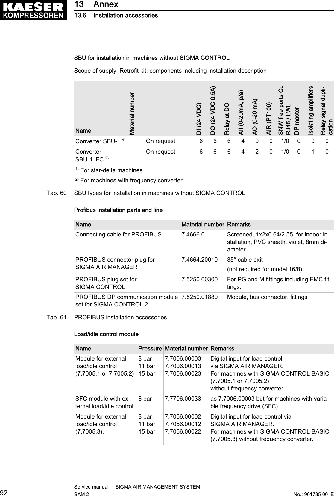
![Technician's settings Tab. 48 Technician's settings13.5 Machine settings13.5.1 Setting the pressure regulation (pressure controller in series with the SAM 2load output)See instructions in chapter 6.12.3Setting suggestion for machines with an "external load control" actuating input [bar]The reference point is the maximum working pressure➤ Adjust the setting values for the pressure regulation (pressure switch (-B1) or systempressure) as follows:Machine number Cut-in pressure Cut-out pressureMaximum working pressure 1 bar to 2.5 bar:Machine 1/5 ON − 0.10 OFF + 0.05Machine 2/6 ON − 0.15 OFF + 0.05Machine 3/7 ON − 0.20 OFF + 0.05Machine 4/8 ON − 0.25 OFF + 0.0513 Annex13.5 Machine settingsNo.: 901735 00 EService manual SIGMA AIR MANAGEMENT SYSTEMSAM 2 85](https://usermanual.wiki/Prodrive-Technologies/SAM2/User-Guide-2427703-Page-95.png)
![Machine number Cut-in pressure Cut-out pressureMaximum working pressure 2.5 bar to 6 bar:Machine 1/5 ON − 0.2 OFF + 0.2Machine 2/6 ON − 0.4 OFF + 0.2Machine 3/7 ON − 0.6 OFF + 0.2Machine 4/8 ON − 0.8 OFF + 0.2Maximum working pressure 6 bar to 16 bar:Machine 1/5 ON − 0.4 OFF + 0.3Machine 2/6 ON − 0.7 OFF + 0.3Machine 3/7 ON − 1.0 OFF + 0.3Machine 4/8 ON – 1.3 OFF + 0.3Maximum working pressure 16 bar to 32 bar:Machine 1/5 ON − 4.0 OFF + 1.0Machine 2/6 ON − 5.0 OFF + 1.0Machine 3/7 ON − 6.0 OFF + 1.0Machine 4/8 ON − 7.0 OFF + 1.0Tab. 49 Recommended settings: Pressure controller in series with SAM 2 "external load control" load out‐putSetting suggestion for machines with the "Man/Auto"/ "Load/Idle" operating mode" control input[bar]The reference point is the maximum working pressure➤ Adjust the setting values for the pressure regulation (pressure switch (-B1) or systempressure) as follows:Machine number Cut-in pressure Cut-out pressureMaximum working pressure 1 bar to 2.5 bar:all ON − 0.10 OFF + 0.05Maximum working pressure 2.5 bar to 6 bar:all ON − 0.2 OFF + 0.2Maximum working pressure 6 bar to 16 bar:all ON − 0.4 OFF + 0.3Maximum working pressure 16 bar to 32 bar:all ON − 4.0 OFF + 1.0Tab. 50 Recommended settings: Pressure controller in series with the SAM 2 "Man/Auto and Load/Idle"load output13 Annex13.5 Machine settings86Service manual SIGMA AIR MANAGEMENT SYSTEMSAM 2 No.: 901735 00 E](https://usermanual.wiki/Prodrive-Technologies/SAM2/User-Guide-2427703-Page-96.png)
![Personal settingsDate/timeSwitching point ON OFF ON OFF ON OFFUnitMachine1 [bar]Machine 2 [bar]Machine 3 [bar]Machine 4 [bar]Machine 5 [bar]Machine 6 [bar]Machine 7 [bar]Machine 8 [bar]Machine 9 [bar]Machine 10 [bar]Machine 11 [bar]Machine 12 [bar]Machine 13 [bar]Machine 14 [bar]Machine 15 [bar]Machine 16 [bar]Tab. 51 Personal settings: Pressure controller in series with SAM 2 load output13.5.2 Pressure range for manual operationTo avoid simultaneous cut-in of machines in manual mode, you must set the system pressure p2and/or system pressure switch −B1.1.Suggested setting [bar]:Machine number Cut-in pressure Cut-out pressureMaximum working pressure 1 bar:Machine 1/5/9/13 ON 0.93 OFF 1.00Machine 2/6/10/14 ON 0.91 OFF 0.98Machine 3/7/11/15 ON 0.89 OFF 0.96Machine 4/8/12/16 ON 0.87 OFF 0.94Maximum working pressure 7.5 bar:Machine 1/5/9/13 ON 7.0 OFF 7.5Machine 2/6/10/14 ON 6.7 OFF 7.2Machine 3/7/11/15 ON 6.4 OFF 6.9Machine 4/8/12/16 ON 6.1 OFF 6.6Maximum working pressure 10 bar:13 Annex13.5 Machine settingsNo.: 901735 00 EService manual SIGMA AIR MANAGEMENT SYSTEMSAM 2 87](https://usermanual.wiki/Prodrive-Technologies/SAM2/User-Guide-2427703-Page-97.png)
![Machine number Cut-in pressure Cut-out pressureMachine 1/5/9/13 ON 9.3 OFF 10.0Machine 2/6/10/14 ON 9.0 OFF 9.7Machine 3/7/11/15 ON 8.7 OFF 9.4Machine 4/8/12/16 ON 8.4 OFF 9.1Maximum working pressure 13 bar:Machine 1/5/9/13 ON 12.3 OFF 13.0Machine 2/6/10/14 ON 12.0 OFF 12.7Machine 3/7/11/15 ON 11.7 OFF 12.4Machine 4/8/12/16 ON 11.4 OFF 12.1Maximum working pressure 25 bar:Machine 1/5/9/13 ON 22 OFF 25Machine 2/6/10/14 ON 21 OFF 24Machine 3/7/11/15 ON 20 OFF 23Machine 4/8/12/16 ON 19 OFF 22Maximum working pressure 32 bar:Machine 1/5/9/13 ON 27 OFF 32Machine 2/6/10/14 ON 26 OFF 31Machine 3/7/11/15 ON 25 OFF 30Machine 4/8/12/16 ON 24 OFF 29Tab. 52 Recommended settings: Pressure range for manual operationPersonal settingsDate/timeSwitching point ON OFF ON OFF ON OFFUnitMachine1 [bar]Machine 2 [bar]Machine 3 [bar]Machine 4 [bar]Machine 5 [bar]Machine 6 [bar]Machine 7 [bar]Machine 8 [bar]Machine 9 [bar]Machine 10 [bar]Machine 11 [bar]Machine 12 [bar]Machine 13 [bar]13 Annex13.5 Machine settings88Service manual SIGMA AIR MANAGEMENT SYSTEMSAM 2 No.: 901735 00 E](https://usermanual.wiki/Prodrive-Technologies/SAM2/User-Guide-2427703-Page-98.png)
![Date/timeSwitching point ON OFF ON OFF ON OFFUnitMachine 14 [bar]Machine 15 [bar]Machine 16 [bar]Tab. 53 Personal settings: Pressure range for manual operation13.5.3 System offset for manual modetv = time delay for switching machines on after a power failureDate/timeNameTime delay tv [s] tv [s] tv [s] tv [s] tv [s] tv [s]Machine1Machine 2Machine 3Machine 4Machine 5Machine 6Machine 7Machine 8Machine 9Machine 10Machine 11Machine 12Machine 13Machine 14Machine 15Machine 16Tab. 54 Personal settings: System offset (manual operation)13 Annex13.5 Machine settingsNo.: 901735 00 EService manual SIGMA AIR MANAGEMENT SYSTEMSAM 2 89](https://usermanual.wiki/Prodrive-Technologies/SAM2/User-Guide-2427703-Page-99.png)