Proform 831216520 User Manual XP 110 R Manuals And Guides L0702362
PROFORM Cycle Manual L0702362 PROFORM Cycle Owner's Manual, PROFORM Cycle installation guides
User Manual: Proform 831216520 831216520 PROFORM PROFORM XP 110 R - Manuals and Guides View the owners manual for your PROFORM PROFORM XP 110 R #831216520. Home:Fitness Equipment Parts:Proform Parts:Proform PROFORM XP 110 R Manual
Open the PDF directly: View PDF ![]() .
.
Page Count: 24
Model No. 831.21652.0
Serial No.
Serial
Decal
• Assembly
•Operation
•Maintenance
•Part List and Drawing
_CAUTION
Read all precautions and instruc-
tions in this manual before using
this equipment. Keep this manual
for future reference.
BIKE EXERCISER
User's Manual
Sears, Roebuck and Co., Hoffman Estates, IL 60179
TABLE OF CONTENTS
IMPORTANT PRECAUTIONS ................................................................ 2
BEFORE YOU BEGIN ...................................................................... 3
ASSEMBLY ............................................................................... 4
HOW TO OPERATE THE EXERCISE CYCLE ................................................... 10
MAINTENANCE AND TROUBLESHOOTING ................................................... 18
CYCLING EXERCISE GUIDELINES .......................................................... 19
STRENGTH EXERCISE GUIDELINES ........................................................ 20
PART LIST .............................................................................. 22
EXPLODED DRAWING .................................................................... 23
HOW TO ORDER REPLACEMENT PARTS ............................................. Back Cover
90 DAY FULL WARRANTY .......................................................... Back Cover
IMPORTANT PRECAUTIONS
WARNING: To reduce the risk of serious injury, read the following important precau-
tions before using the exercise cycle.
1. Read all instructions in this manual and all
warnings on the exercise cycle before using
the exercise cycle. Use the exercise cycle only
as described in this manual.
8. Wear appropriate clothes while exercising;
do not wear loose clothes that could become
caught on the exercise cycle. Always wear
athletic shoes for foot protection.
2. It is the responsibility of the owner to ensure
that all users of the exercise cycle are ade-
quately informed of all precautions.
3. The exercise cycle is intended for home use
only. Do not use the exercise cycle in
a commercial, rental, or institutional setting.
4. Keep the exercise cycle indoors, away from
moisture and dust. Place the exercise cycle
9. The pulse sensor is not a medical device.
Various factors, including the user's move-
ment, may affect the accuracy of heart rate
readings. The pulse sensor is intended only
as an exercise aid in determining heart rate
trends in general.
10. Always keep your back straight while using
the exercise cycle; do not arch your back.
on a level surface, with a mat beneath it to 11. If you feel pain or dizziness while exercising,
protect the floor. Make sure that there is stop immediately and cool down.
enough clearance around the exercise cycle
to mount, dismount, and use it. 12. The exercise cycle does not have a freewheel;
the pedals will continue to move until the fly-
5. Inspect and properly tighten all parts regularly, wheel stops.
Re place any worn parts immediately.
13. The warning decals shown on page 3 have
6. Keep children under the age of 12 and pets
away from the exercise cycle at all times.
7. The exercise cycle should not be used by
persons weighing more than 250 pounds.
been placed on the exercise cycle. If a decal
is missing or illegible, call toll-free
1-888-533-1333 and request a free re place-
ment decal. Apply the decal in the location
shown.
WARNING: Before beginning this or any exercise program, consult your physician. This
is especially important for persons over the age of 35 or persons with pre-existing health problems.
Read all instructions before using. Sears assumes no responsibility for personal injury or property
damage sustained by or through the use of this product.
BEFORE YOU BEGIN
Congratulations for selecting the new PREFORM ®XP
110 R exercise cycle. Cycling is one of the most effec-
tive exercises for increasing cardiovascular fitness,
building endurance, and toning the entire body. The
XP 110 R exercise cycle offers a selection of features
designed to let you enjoy this healthful exercise in the
convenience and privacy of your home.
For your benefit, read this manual carefully before
you use the exercise cycle. If you have questions
after reading this manual, call 1-800-4-MY-HeMP
(1-800-469-4663). To help us assist you, please note
the product model number and serial number before
contacting us. The model number is 831.21 652.0. The
serial number can be found on a decal attached to the
exercise cycle (see the front cover of this manual).
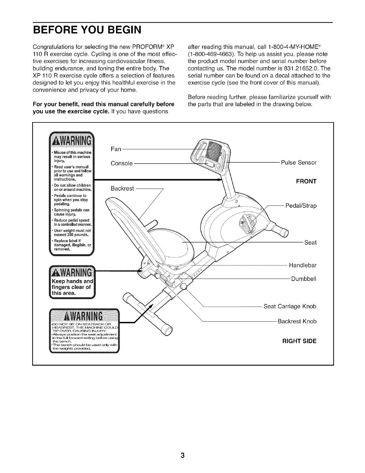
Before reading further, please familiarize yourself with
the parts that are labeled in the drawing below.
•Misuseofthis machine
may result in serious
injury,
,Read user's manual
prior to use and follow
all warnings and
instructions.
•Do net allow children
on or around machine.
, Pedals continue to
spin when you stop
pedaling.
,Spinning pedals can
cause injury.
•Reduce pedal speed
in acontrolled manner,
, User weight must not
exceed 250 pounds.
• Replace label if
damaged, illegible, or
removed.
Fan
Console
Backrest
Pulse Sensor
FRONT
_=dal/Strap
Seat
Keep hands and
fingers clear of
this ares,
"DO NOT SIr ON S F_Zkl]3ACK OR
lip OVFR, CAUSING INJURY.
-Always position the seat adj u sln_lent
in the full forward soten(
the ber_ch.
-The bench should _ u_'d only with
the weighi_ provided.
Handlebar
Dumbbell
Seat Carriage Knob
Backrest Knob
RIGHT SIDE
ASSEMBLY
Assembly requires two persons. Place all parts of the exercise cycle in a cleared area and remove the packing
materials. Do not dispose of the packing materials until assembly is completed.
Assembly requires the included tools and your own adjustable wrench _ and Phillips
screwdriver _-_=_.
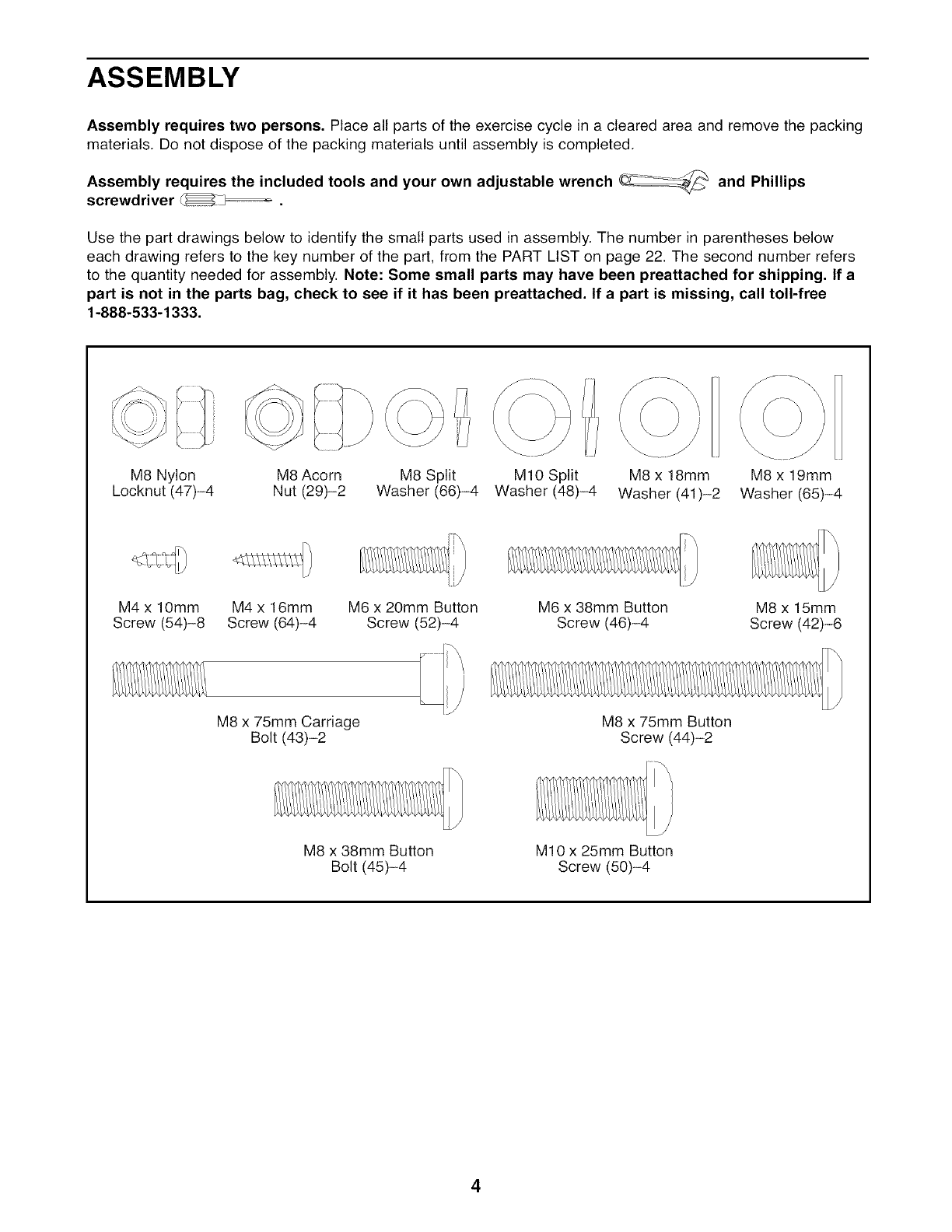
Use the part drawings below to identify the small parts used in assembly. The number in parentheses below
each drawing refers to the key number of the part, from the PART LIST on page 22. The second number refers
to the quantity needed for assembly. Note: Some small parts may have been preattached for shipping. If a
part is not in the parts bag, check to see if it has been preattached. If a part is missing, call toll-free
1-888-533-1333.
M8 Nylon M8 Acorn M8 Split MIO Split M8 x 18mm M8 x 19mm
Locknut (47)-4 Nut (29)-2 Washer (66)-4 Washer (48)-4 Washer (41)-2 Washer (65)-4
M4 x lOmm M4 x 16mm M6 x 20mm Button M6 x 38mm Button M8 x 15mm
Screw (54)-8 Screw (64)-4 Screw (52)-4 Screw (46)-4 Screw (42)-6
M8 x 75mm Carriage
Bolt (43)-2 M8 x 75mm Button
Screw (44)-2
M8 x 38mm Button
Bolt (45)-4 M10 x 25mm Button
Screw (50)-4
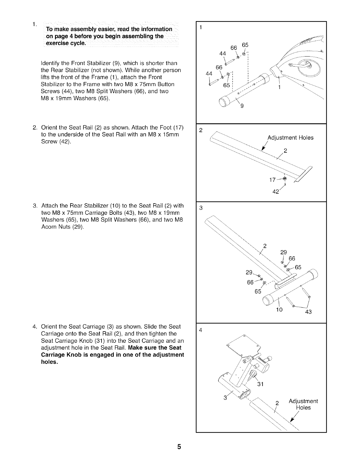
To make assembly easier, read the information
on page4 before you begin assembling the
Identify the Front Stabilizer (9), which is shorter than
the Rear Stabilizer (not shown). While another person
lifts the front of the Frame (1), attach the Front
Stabilizer to the Frame with two M8 x 75mm Button
Screws (44), two M8 Split Washers (66), and two
M8 x 19mm Washers (65).
2. Orient the Seat Rail (2) as shown. Attach the Foot (17)
to the underside of the Seat Rail with an M8 x 15mm
Screw (42).
3. Attach the Rear Stabilizer (10) to the Seat Rail (2) with
two M8 x 75mm Carriage Bolts (43), two M8 x 19mm
Washers (65), two M8 Split Washers (66), and two M8
Acorn Nuts (29).
4. Orient the Seat Carriage (3) as shown. Slide the Seat
Carriage onto the Seat Rail (2), and then tighten the
Seat Carriage Knob (31) into the Seat Carriage and an
adjustment hole in the Seat Rail. Make sure the Seat
Carriage Knob is engaged in one of the adjustment
holes.
44
Adjustment Holes
2
229 66
65
10 43
31
2 Adjustment
Holes
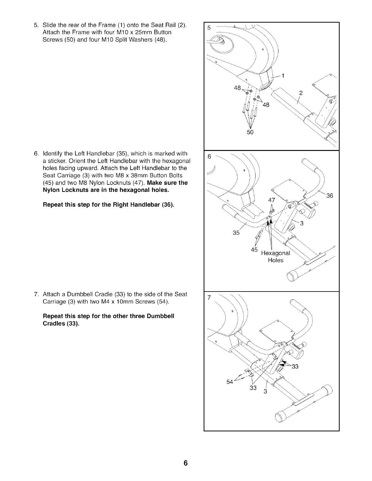
5. SlidetherearoftheFrame(1)ontotheSeatRail(2).
AttachtheFramewithfourM10x 25mmButton
Screws(50)andfourM10SplitWashers(48).
,Identify the Left Handlebar (35), which is marked with
a sticker. Orient the Left Handlebar with the hexagonal
holes facing upward. Attach the Left Handlebar to the
Seat Carriage (3) with two M8 x 38mm Button Bolts
(45) and two M8 Nylon Locknuts (47). Make sure the
Nylon Loeknuts are in the hexagonal holes.
Repeat this step for the Right Handlebar (36).
7. Attach a Dumbbell Cradle (33) to the side of the Seat
Carriage (3) with two M4 x 10mm Screws (54).
Repeat this step for the other three Dumbbell
Cradles (33),
5
35
45 Hexagonal
Holes
7
33
36
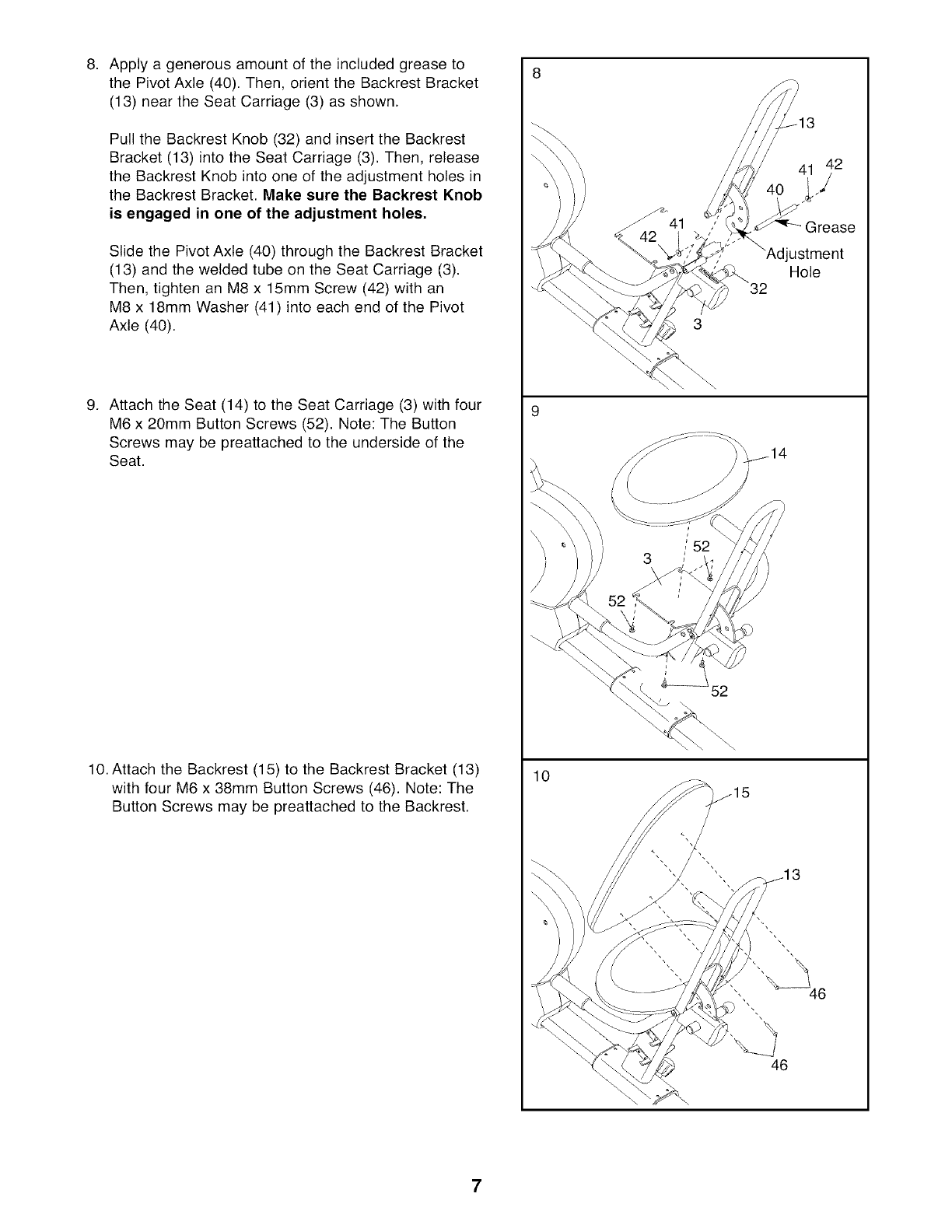
8. Applyagenerousamountoftheincludedgreaseto
thePivotAxle(40).Then,orienttheBackrestBracket
(13)neartheSeatCarriage(3)asshown.
PulltheBackrestKnob(32)andinserttheBackrest
Bracket(13)intotheSeatCarriage(3).Then,release
theBackrestKnobintooneoftheadjustmentholesin
theBackrestBracket.Makesurethe BackrestKnob
is engagedin oneof the adjustmentholes.
SlidethePivotAxle(40)throughtheBackrestBracket
(13)andtheweldedtubeontheSeatCarriage(3).
Then,tightenanM8x 15mmScrew(42)withan
M8x 18mmWasher(41)intoeachendofthePivot
Axle(40).
9. AttachtheSeat(14)to theSeatCarriage(3)withfour
M6x 20mmButtonScrews(52).Note:TheButton
Screwsmaybepreattachedto theundersideofthe
Seat.
10.AttachtheBackrest(15)to theBackrestBracket(13)
withfourM6x 38mmButtonScrews(46).Note:The
ButtonScrewsmaybepreattachedto theBackrest.
10
41
Grease
ustment
Hole
52
46
7
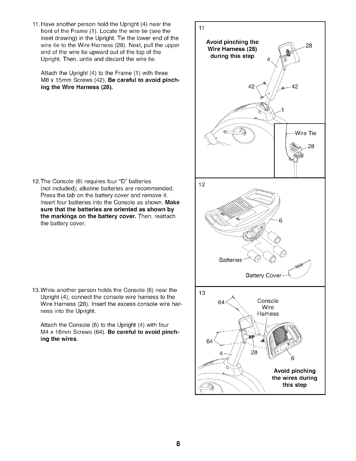
11. Have another person hold the Upright (4) near the
front of the Frame (1). Locate the wire tie (see the
inset drawing) in the Upright. Tie the lower end of the
wire tie to the Wire Harness (28). Next, pull the upper
end of the wire tie upward out of the top of the
Upright. Then, untie and discard the wire tie.
Attach the Upright (4) to the Frame (1) with three
M8 x 15mm Screws (42). Be careful to avoid pinch-
ing the Wire Harness (28).
12.The Console (6) requires four "D" batteries
(not included); alkaline batteries are recommended.
Press the tab on the battery cover and remove it.
Insert four batteries into the Console as shown. Make
sure that the batteries are oriented as shown by
the markings on the battery cover. Then, reattach
the battery cover.
13.While another person holds the Console (6) near the
Upright (4), connect the console wire harness to the
Wire Harness (28). Insert the excess console wire har-
ness into the Upright.
Attach the Console (6) to the Upright (4) with four
M4 x 16mm Screws (64). Be careful to avoid pinch-
ing the wires.
11
Avoid pinching the _ ^
Wire Harness (28) _2_
during this steP_42 _!__ 42
_--_ _-_" /Wire Tie
12
Battery Cover_
13
Console
Wire
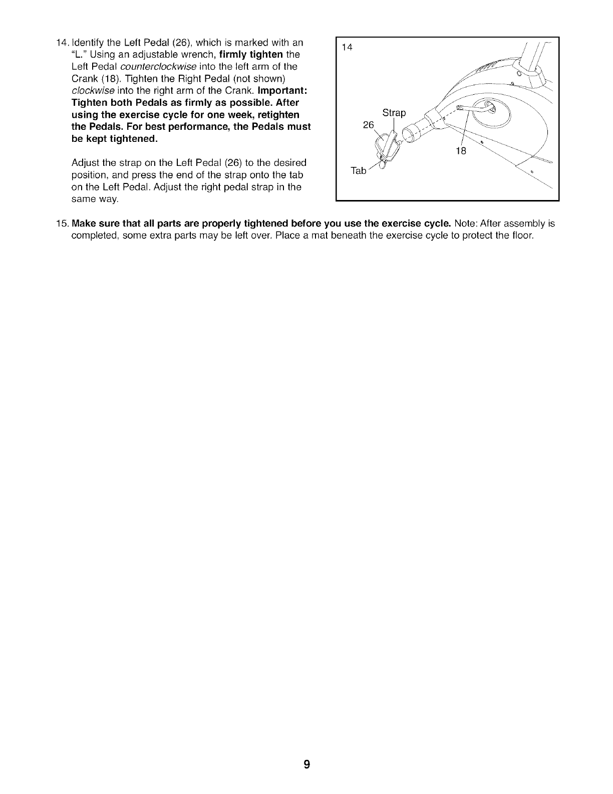
14.IdentifytheLeftPedal(26),whichismarkedwithan
"L."Usinganadjustablewrench,firmly tightenthe
LeftPedalcounterclockwise into the left arm of the
Crank (18). Tighten the Right Pedal (not shown)
clockwise into the right arm of the Crank. Important:
Tighten both Pedals as firmly as possible. After
using the exercise cycle for one week, retighten
the Pedals. For best performance, the Pedals must
be kept tightened.
Adjust the strap on the Left Pedal (26) to the desired
position, and press the end of the strap onto the tab
on the Left Pedal. Adjust the right pedal strap in the
same way.
14
Stra
26\
18
15. Make sure that all parts are properly tightened before you use the exercise cycle. Note: After assembly is
completed, some extra parts may be left over. Place a mat beneath the exercise cycle to protect the floor.
9
HOW TO OPERATE THE EXERCISE CYCLE
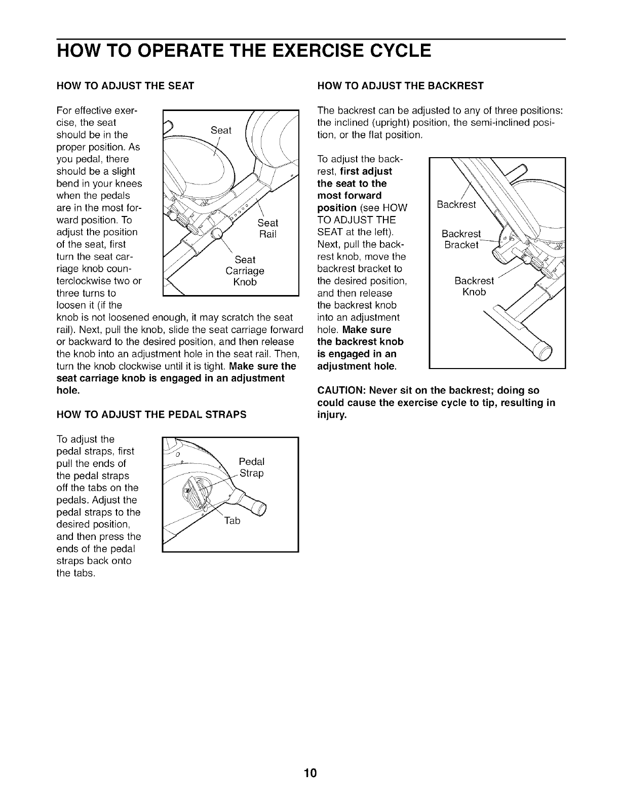
HOW TO ADJUST THE SEAT
For effective exer-
cise, the seat
should be in the
proper position. As
you pedal, there
should be a slight
bend in your knees
when the pedals
are in the most for-
ward position. To
adjust the position
of the seat, first
turn the seat car-
riage knob coun-
terclockwise two or
three turns to
loosen it (if the
Seat
Seat
Rail
Seat
Carriage
_b
knob is not loosened enough, it may scratch the seat
rail). Next, pull the knob, slide the seat carriage forward
or backward to the desired position, and then release
the knob into an adjustment hole in the seat rail. Then,
turn the knob clockwise until it is tight. Make sure the
seat carriage knob is engaged in an adjustment
hole.
HOW TO ADJUST THE PEDAL STRAPS
To adjust the
pedal straps, first
pull the ends of
the pedal straps
off the tabs on the
pedals. Adjust the
pedal straps to the
desired position,
and then press the
ends of the pedal
straps back onto
the tabs.
_.__ ............ Pedal
Tab
J
HOW TO ADJUST THE BACKREST
The backrest can be adjusted to any of three positions:
the inclined (upright) position, the semi-inclined posi-
tion, or the flat position.
To adjust the back-
rest, first adjust
the seat to the
most forward
position (see HOW
TO ADJUST THE
SEAT at the left).
Next, pull the back-
rest knob, move the
backrest bracket to
the desired position,
and then release
the backrest knob
into an adjustment
hole. Make sure
the backrest knob
is engaged in an
adjustment hole.
Backrest
Bracket
Knob
CAUTION: Never sit on the backrest; doing so
could cause the exercise cycle to tip, resulting in
injury.
10
FAN
PROGRAM
ERL.5 BBP_.
CLJ'U !
TIME
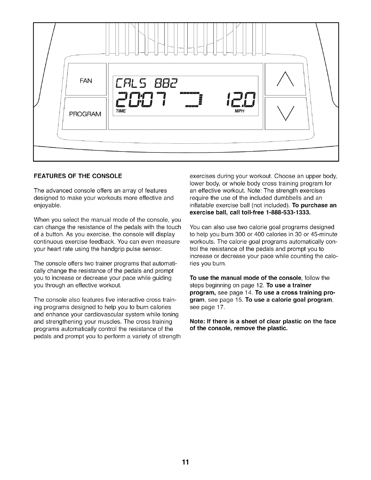
FEATURES OF THE CONSOLE
The advanced console offers an array of features
designed to make your workouts more effective and
enjoyable.
When you select the manual mode of the console, you
can change the resistance of the pedals with the touch
of a button. As you exercise, the console will display
continuous exercise feedback. You can even measure
your heart rate using the handgrip pulse sensor.
The console offers two trainer programs that automati-
cally change the resistance of the pedals and prompt
you to increase or decrease your pace while guiding
you through an effective workout.
The console also features five interactive cross train-
ing programs designed to help you to burn calories
and enhance your cardiovascular system while toning
and strengthening your muscles. The cross training
programs automatically control the resistance of the
pedals and prompt you to perform a variety of strength
exercises during your workout. Choose an upper body,
lower body, or whole body cross training program for
an effective workout. Note: The strength exercises
require the use of the included dumbbells and an
inflatable exercise ball (not included). To purchase an
exercise ball, call toll-free 1-888-533-1333.
You can also use two calorie goal programs designed
to help you burn 300 or 400 calories in 30 or 45-minute
workouts. The calorie goal programs automatically con-
trol the resistance of the pedals and prompt you to
increase or decrease your pace while counting the calo-
ries you burn.
To use the manual mode of the console, follow the
steps beginning on page 12. To use a trainer
program, see page 14. To use a cross training pro-
gram, see page 15. To use a calorie goal program,
see page 17.
Note: If there is a sheet of clear plastic on the face
of the console, remove the plastic.
11
HOW TO USE THE MANUAL MODE
D ress any button or begin pedaling to turn on
the console.
A moment after you turn on the console, the dis-
play will light.
BSelect the manual mode,
Each time you turn on the console, the manual
mode will be selected automatically. If you have
selected a program, reselect the manual mode by
pressing the Programs button repeatedly until the
words MANUAL MODE appear in the top of the
display.
_egin pedaling and change the resistance of
the pedals as desired,
As you pedal, change the resistance of the ped-
als by pressing the Increase and Decrease but-
tons repeatedly. There are ten resistance levels.
Note: After you press the buttons, it will take a
moment for the pedals to reach the selected
resistance level.
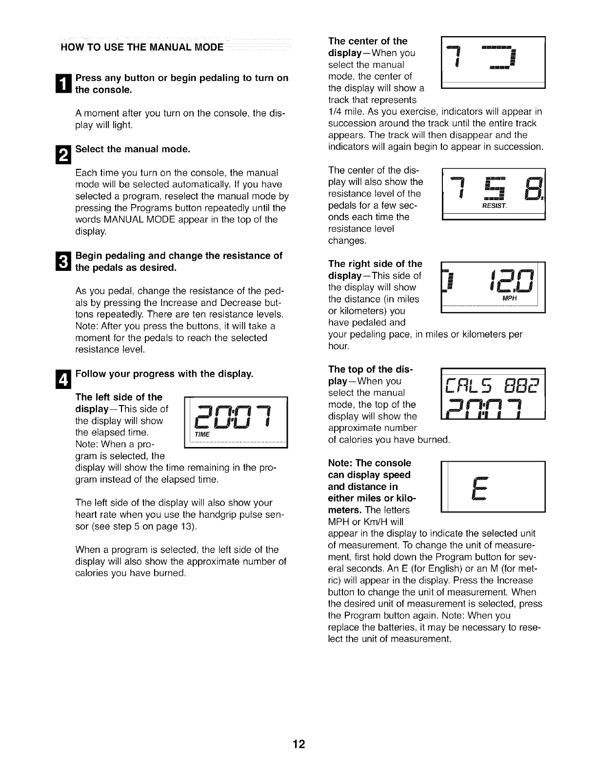
BFollow your progress with the display.
The left side of the
display--This side of
the display will show
the elapsed time.
Note: When a pro-
gram is selected, the
CU'U I
display will show the time remaining in the pro-
gram instead of the elapsed time.
The left side of the display will also show your
heart rate when you use the handgrip pulse sen-
sor (see step 5 on page 13).
When a program is selected, the left side of the
display will also show the approximate number of
calories you have burned.
The center of the
display--When you "_ ....
select the manual _ .... W
mode, the center of
the display will show a
track that represents
1/4 mile. As you exercise, indicators will appear in
succession around the track until the entire track
appears. The track will then disappear and the
indicators will again begin to appear in succession.
The center of the dis-
play will also show the
resistance level of the
pedals for a few sec-
onds each time the
resistance level
changes.
" B.I
RESIST.
The right side of the
display--This side of
the display will show
the distance (in miles
or kilometers) you
have pedaled and
your pedaling pace, in miles or kilometers per
hour.
The top of the dis-
play--When you
select the manual
mode, the top of the
display will show the
approximate number
of calories you have burned.
LRL 5 BB2
pm.m
j I=J J
Note: The console I
I
can display speed
and distance in L
either miles or kilo-
meters, The letters
MPH or Km/H will
appear in the display to indicate the selected unit
of measurement. To change the unit of measure-
ment, first hold down the Program button for sev-
eral seconds. An E (for English) or an M (for met-
ric) will appear in the display. Press the Increase
button to change the unit of measurement. When
the desired unit of measurement is selected, press
the Program button again. Note: When you
replace the batteries, it may be necessary to rese-
lect the unit of measurement.
12
0Measure your heart rate if desired.
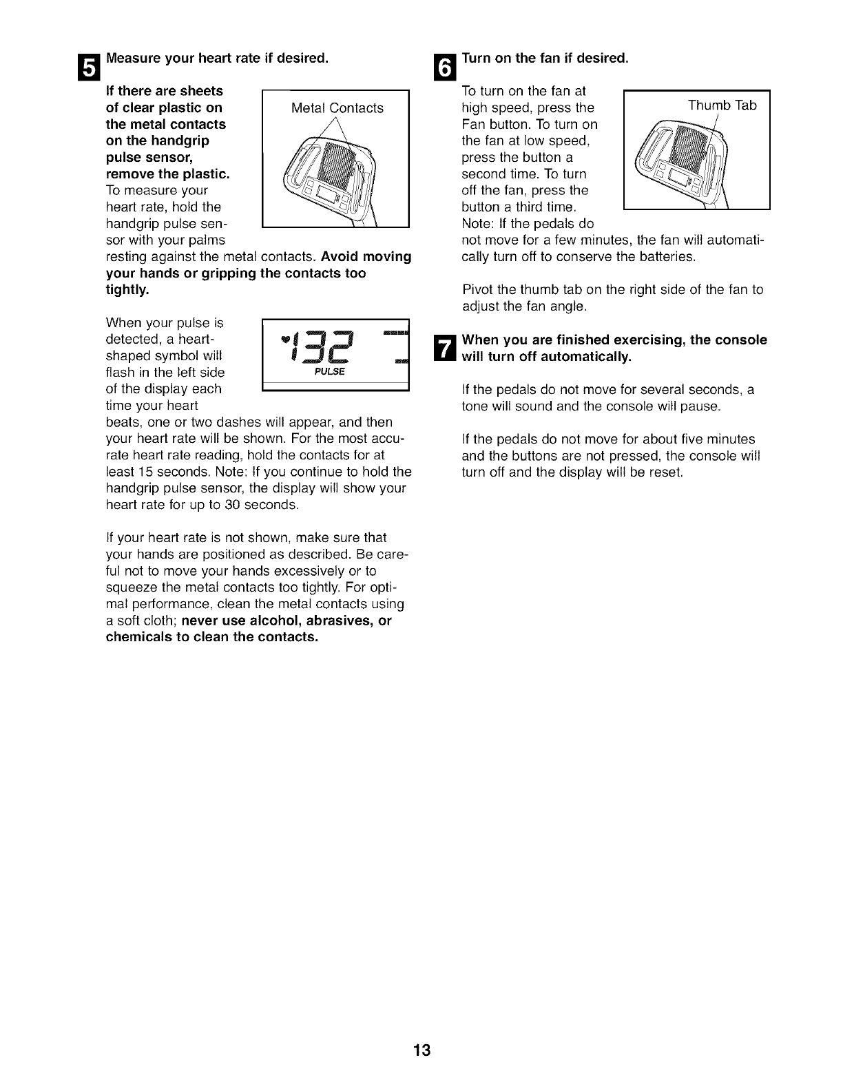
If there are sheets
of clear plastic on
the metal contacts
on the handgrip
pulse sensor,
remove the plastic.
To measure your
heart rate, hold the
handgrip pulse sen-
sor with your palms
I MetalContact
resting against the metal contacts. Avoid moving
your hands or gripping the contacts too
tightly.
When your pulse is
detected, a heart-
shaped symbol will
flash in the left side
of the display each
time your heart
beats, one or two dashes will appear, and then
your heart rate will be shown. For the most accu-
rate heart rate reading, hold the contacts for at
least 15 seconds. Note: If you continue to hold the
handgrip pulse sensor, the display will show your
heart rate for up to 30 seconds.
If your heart rate is not shown, make sure that
your hands are positioned as described. Be care-
ful not to move your hands excessively or to
squeeze the metal contacts too tightly. For opti-
mal performance, clean the metal contacts using
a soft cloth; never use alcohol, abrasives, or
chemicals to clean the contacts.
Turn on the fan if desired.
To turn on the fan at
high speed, press the Thumb Tab
Fan button. To turn on
the fan at low speed,
press the button a
second time. To turn
off the fan, press the
button a third time.
Note: If the pedals do
not move for a few minutes, the fan will automati-
cally turn off to conserve the batteries.
Pivot the thumb tab on the right side of the fan to
adjust the fan angle.
B hen you are finished exercising, the console
will turn off automatically.
If the pedals do not move for several seconds, a
tone will sound and the console will pause.
If the pedals do not move for about five minutes
and the buttons are not pressed, the console will
turn off and the display will be reset.
13
HOW TO USE A TRAINER PROGRAM
D ress any button or begin pedaling to turn on
the console.
A moment after you turn on the console, the dis-
play will light.
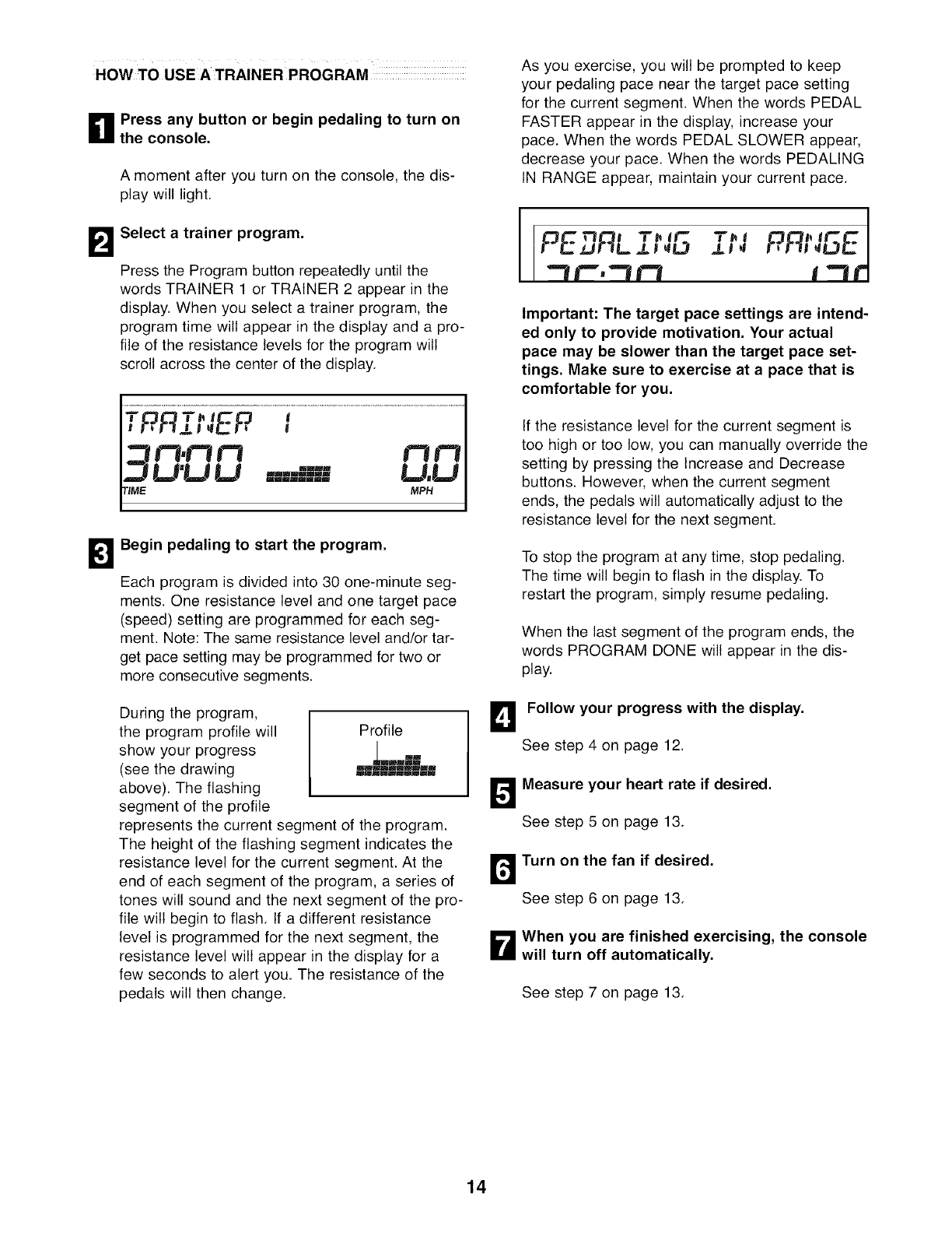
BSelect a trainer program.
Press the Program button repeatedly until the
words TRAINER 1 or TRAINER 2 appear in the
display. When you select a trainer program, the
program time will appear in the display and a pro-
file of the resistance levels for the program will
scroll across the center of the display.
TOOT_ i_O l
i!-_ J-1.LJP_[,._t-_ I
m.f"lB"I f"wf'l
ZJLI'LI LI ===-===m=-= U.LI
TIME MPH
IgBegin pedaling to start the program.
Each program is divided into 30 one-minute seg-
ments. One resistance level and one target pace
(speed) setting are programmed for each seg-
ment. Note: The same resistance level and/or tar-
get pace setting may be programmed for two or
more consecutive segments.
During the program,
the program profile will Profile
show your progress | Im
(see the drawing m,,-,,,k,,,'%,"='L,m=
above). The flashing
segment of the profile
represents the current segment of the program.
The height of the flashing segment indicates the
resistance level for the current segment. At the
end of each segment of the program, a series of
tones will sound and the next segment of the pro-
file will begin to flash. If a different resistance
level is programmed for the next segment, the
resistance level will appear in the display for a
few seconds to alert you. The resistance of the
pedals will then change.
As you exercise, you will be prompted to keep
your pedaling pace near the target pace setting
for the current segment. When the words PEDAL
FASTER appear in the display, increase your
pace. When the words PEDAL SLOWER appear,
decrease your pace. When the words PEDALING
IN RANGE appear, maintain your current pace.
Important: The target pace settings are intend-
ed only to provide motivation. Your actual
pace may be slower than the target pace set-
tings. Make sure to exercise at a pace that is
comfortable for you.
If the resistance level for the current segment is
too high or too low, you can manually override the
setting by pressing the Increase and Decrease
buttons. However, when the current segment
ends, the pedals will automatically adjust to the
resistance level for the next segment.
To stop the program at any time, stop pedaling.
The time will begin to flash in the display. To
restart the program, simply resume pedaling.
When the last segment of the program ends, the
words PROGRAM DONE will appear in the dis-
play.
BFollow your progress with the display.
See step 4 on page 12.
_easure your heart rate if desired.
See step 5 on page 13.
r_ Turn on the fan if desired.
See step 6 on page 13.
D hen you are finished exercising, the console
will turn off automatically.
See step 7 on page 13.
14
HOW TO USE ACROSS TRAINING PROGRAM
_1 Press any button or begin pedaling to turn on
the console,
A moment after you turn on the console, the dis-
play will light.
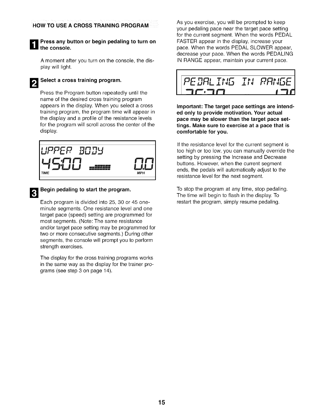
BSelect a cross training program.
Press the Program button repeatedly until the
name of the desired cross training program
appears in the display. When you select a cross
training program, the program time will appear in
the display and a profile of the resistance levels
for the program will scroll across the center of the
display.
UPPEP DU _,.J
! ZJ'U U dMB LJ,LJ
TIME MPH
Begin pedaling to start the program,
Each program is divided into 25, 30 or 45 one-
minute segments. One resistance level and one
target pace (speed) setting are programmed for
most segments. (Note: The same resistance
and/or target pace setting may be programmed for
two or more consecutive segments.) During other
segments, the console will prompt you to perform
strength exercises.
The display for the cross training programs works
in the same way as the display for the trainer pro-
grams (see step 3 on page 14).
As you exercise, you will be prompted to keep
your pedaling pace near the target pace setting
for the current segment. When the words PEDAL
FASTER appear in the display, increase your
pace. When the words PEDAL SLOWER appear,
decrease your pace. When the words PEDALING
IN RANGE appear, maintain your current pace.
PE flL ,.u
""tt"',""tt'l
Important: The target pace settings are intend-
ed only to provide motivation, Your actual
pace may be slower than the target pace set-
tings, Make sure to exercise at a pace that is
comfortable for you,
If the resistance level for the current segment is
too high or too low, you can manually override the
setting by pressing the Increase and Decrease
buttons. However, when the current segment
ends, the pedals will automatically adjust to the
resistance level for the next segment.
To stop the program at any time, stop pedaling.
The time will begin to flash in the display. To
restart the program, simply resume pedaling.
15
B Perform the first strength exercise when
prompted,
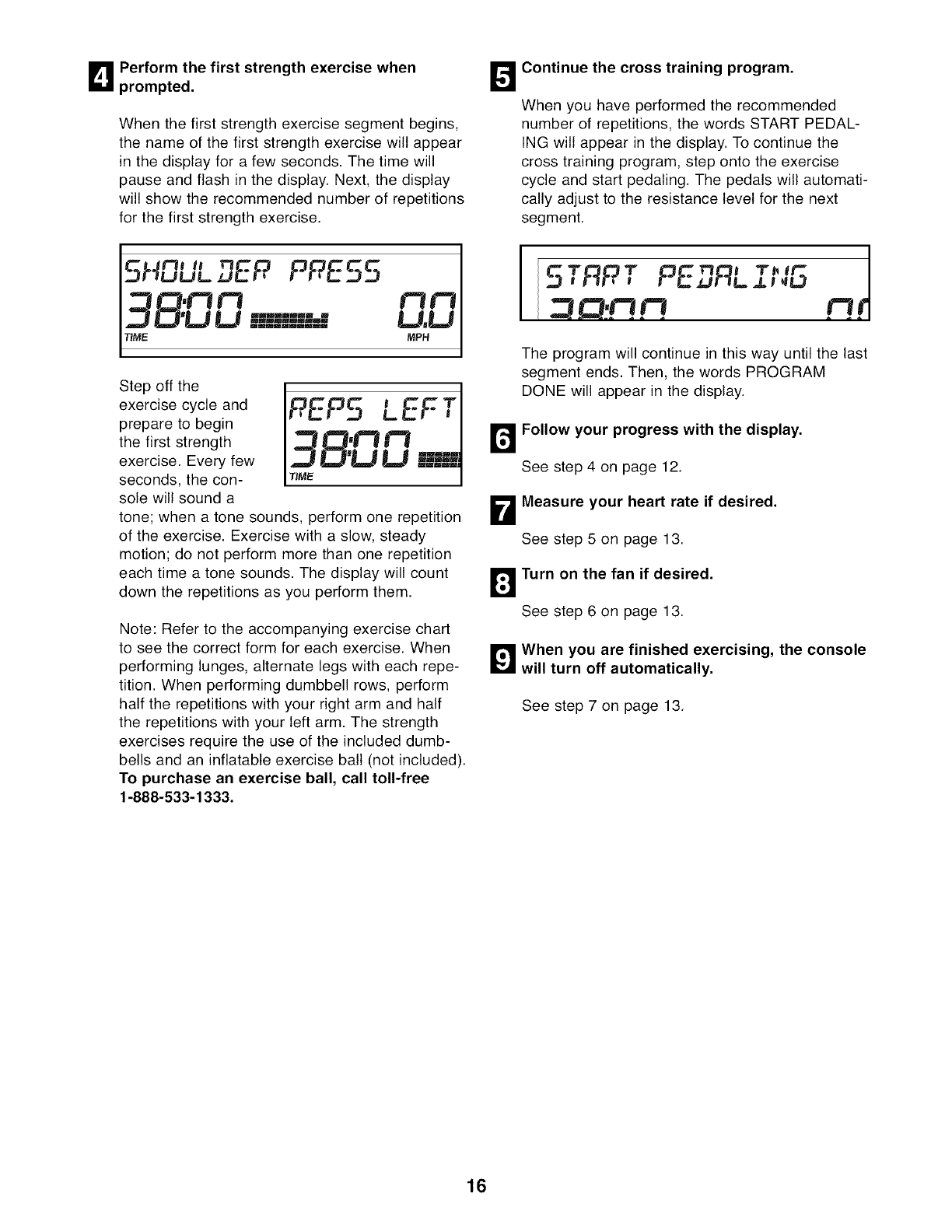
When the first strength exercise segment begins,
the name of the first strength exercise will appear
in the display for a few seconds. The time will
pause and flash in the display. Next, the display
will show the recommended number of repetitions
for the first strength exercise.
O
5klDUL PPE.55
ZJ D'U U mmL=d LJ,U
TIME. MPH
Step off the
exercise cycle and
prepare to begin
the first strength
exercise. Every few
seconds, the con-
sole will sound a
tone; when a tone sounds, perform one repetition
of the exercise. Exercise with a slow, steady
motion; do not perform more than one repetition
each time a tone sounds. The display will count
down the repetitions as you perform them.
B
D
Note: Refer to the accompanying exercise chart
to see the correct form for each exercise. When
performing lunges, alternate legs with each repe-
tition. When performing dumbbell rows, perform
half the repetitions with your right arm and half
the repetitions with your left arm. The strength
exercises require the use of the included dumb-
bells and an inflatable exercise ball (not included).
To purchase an exercise ball, call toll-free
1-888-533-1333.
Continue the cross training program.
When you have performed the recommended
number of repetitions, the words START PEDAL-
ING will appear in the display. To continue the
cross training program, step onto the exercise
cycle and start pedaling. The pedals will automati-
cally adjust to the resistance level for the next
segment.
r- _,,._.ZJ!-I L JL t _k,g
mf
The program will continue in this way until the last
segment ends. Then, the words PROGRAM
DONE will appear in the display.
Follow your progress with the display.
See step 4 on page 12.
Measure your heart rate if desired.
See step 5 on page 13.
Turn on the fan if desired.
See step 6 on page 13.
_'_ When you are finished exercising, the console
will turn off automatically.
See step 7 on page 13.
16
HOW TO USE A CALORIE GOAL PROGRAM
_1 Press any button or begin pedaling to turn on
the console.
B
A moment after you turn on the console, the dis-
play will light.
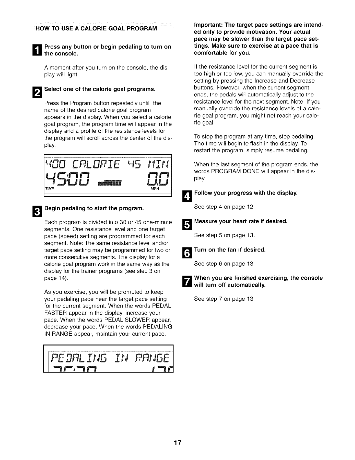
Select one of the calorie goal programs.
Press the Program button repeatedly until the
name of the desired calorie goal program
appears in the display. When you select a calorie
goal program, the program time will appear in the
display and a profile of the resistance levels for
the program will scroll across the center of the dis-
play.
TIME
DBegin pedaling to start the program.
Each program is divided into 30 or 45 one-minute
segments. One resistance level and one target
pace (speed) setting are programmed for each
segment. Note: The same resistance level and/or
target pace setting may be programmed for two or
more consecutive segments. The display for a
calorie goal program work in the same way as the
display for the trainer programs (see step 3 on
page 14).
As you exercise, you will be prompted to keep
your pedaling pace near the target pace setting
for the current segment. When the words PEDAL
FASTER appear in the display, increase your
pace. When the words PEDAL SLOWER appear,
decrease your pace. When the words PEDALING
IN RANGE appear, maintain your current pace.
"3 t","3 t=3 1 "111'
Important: The target pace settings are intend-
ed only to provide motivation. Your actual
pace may be slower than the target pace set-
tings. Make sure to exercise at a pace that is
comfortable for you.
If the resistance level for the current segment is
too high or too low, you can manually override the
setting by pressing the Increase and Decrease
buttons. However, when the current segment
ends, the pedals will automatically adjust to the
resistance level for the next segment. Note: If you
manually override the resistance levels of a calo-
rie goal program, you might not reach your calo-
rie goal.
To stop the program at any time, stop pedaling.
The time will begin to flash in the display. To
restart the program, simply resume pedaling.
When the last segment of the program ends, the
words PROGRAM DONE will appear in the dis-
play.
B ollow your progress with the display.
See step 4 on page 12.
_easure your heart rate if desired.
See step 5 on page 13.
r_ Turn on the fan if desired.
See step 6 on page 13.
B hen you are finished exercising, the console
will turn off automatically.
See step 7 on page 13.
17
MAINTENANCE AND TROUBLESHOOTING
Inspect and properly tighten all parts of the exercise
cycle regularly. Replace any worn parts immediately.
To clean the exercise cycle, use a damp cloth and a
small amount of liquid dish soap. Important: To
avoid damage to the console, keep liquids away
from the console and keep the console out of
direct sunlight,
BATTERY REPLACEMENT
If the console display becomes dim, the batteries
should be replaced; most console problems are the
result of low batteries. To replace the batteries, see
assembly step 12 on page 8.
HOW TO ADJUST THE REED SWITCH
If the console does not display correct feedback, the
reed switch should be adjusted. To adjust the reed
switch, you must first remove the left side shield.
Using an adjustable wrench, turn the left pedal clock-
wise and remove it. Next, remove the screws from
the left side shield. Note: There are different sizes of
screws attaching the left side shield. Be sure to note
the location of each screw. Then, carefully remove
the left side shield.
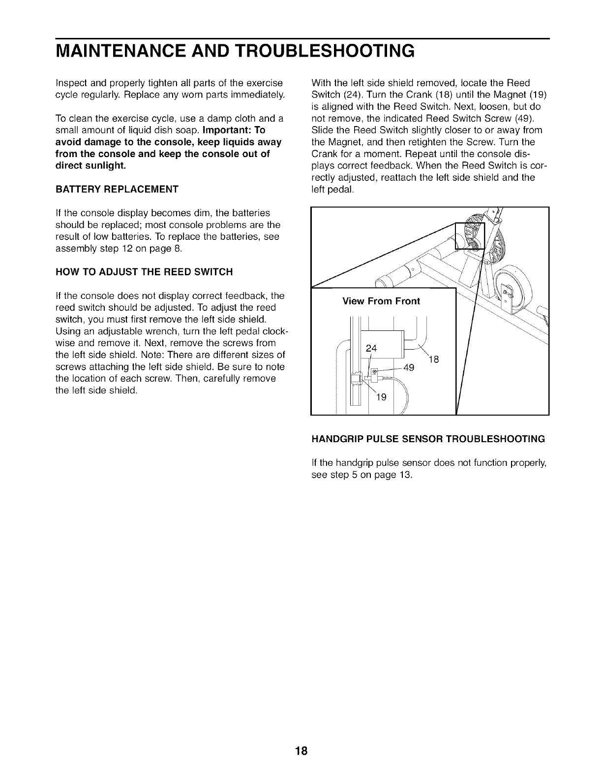
With the left side shield removed, locate the Reed
Switch (24). Turn the Crank (18) until the Magnet (19)
is aligned with the Reed Switch. Next, loosen, but do
not remove, the indicated Reed Switch Screw (49).
Slide the Reed Switch slightly closer to or away from
the Magnet, and then retighten the Screw. Turn the
Crank for a moment. Repeat until the console dis-
plays correct feedback. When the Reed Switch is cor-
rectly adjusted, reattach the left side shield and the
left pedal.
View From Front
f24
18
HANDGRIP PULSE SENSOR TROUBLESHOOTING
If the handgrip pulse sensor does not function properly,
see step 5 on page 13.
18
CYCLING EXERCISE GUIDELINES
The following guidelines will help you to plan your
exercise program. Remember that proper nutrition
and adequate rest are essential for successful results.
WARNING: Beforebeginning
this or any exercise program, consult your
physician. This is especially important for
persons over the age of 35 or persons with
pre-existing health problems.
The pulse sensor is not a medical device.
Various factors may affect the accuracy of
heart rate readings. The pulse sensor is
intended only as an exercise aid in determin-
ing heart rate trends in general.
EXERCISE INTENSITY
Whether your goal is to burn fat or to strengthen your
cardiovascular system, the key to achieving the
desired results is to exercise with the proper intensity.
The proper intensity level can be found by using your
heart rate as a guide. The chart below shows recom-
mended heart rates for fat burning, maximum fat
burning, and cardiovascular (aerobic) exercise.
165 155 145 140 130 125 115 _
145 138 130 125 118 110 103 _)
125 120 115 110 105 95 90
20 30 40 50 60 70 80
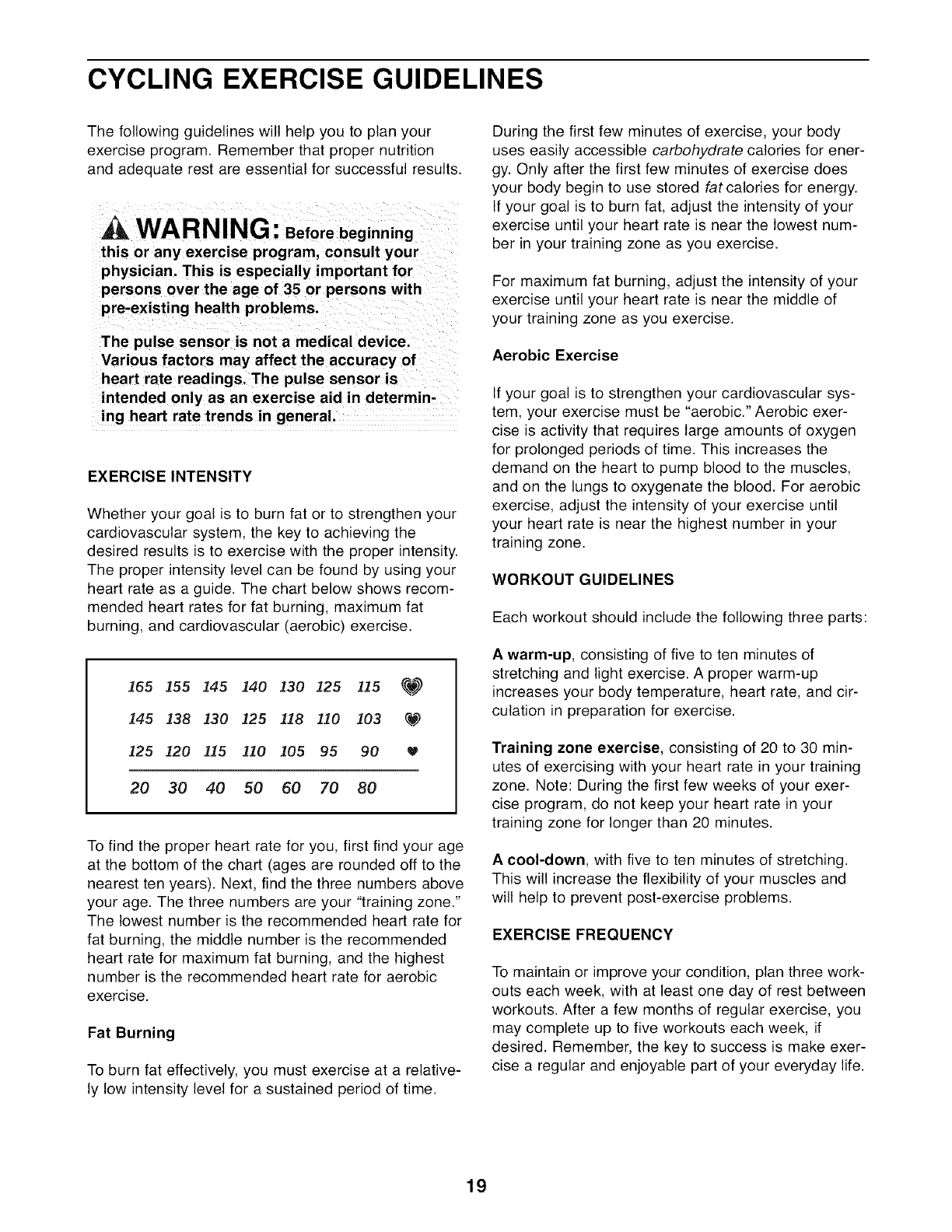
To find the proper heart rate for you, first find your age
at the bottom of the chart (ages are rounded off to the
nearest ten years). Next, find the three numbers above
your age. The three numbers are your "training zone."
The lowest number is the recommended heart rate for
fat burning, the middle number is the recommended
heart rate for maximum fat burning, and the highest
number is the recommended heart rate for aerobic
exercise.
Fat Burning
To burn fat effectively, you must exercise at a relative-
ly low intensity level for a sustained period of time.
During the first few minutes of exercise, your body
uses easily accessible carbohydrate calories for ener-
gy. Only after the first few minutes of exercise does
your body begin to use stored fat calories for energy.
If your goal is to burn fat, adjust the intensity of your
exercise until your heart rate is near the lowest num-
ber in your training zone as you exercise.
For maximum fat burning, adjust the intensity of your
exercise until your heart rate is near the middle of
your training zone as you exercise.
Aerobic Exercise
If your goal is to strengthen your cardiovascular sys-
tem, your exercise must be "aerobic." Aerobic exer-
cise is activity that requires large amounts of oxygen
for prolonged periods of time. This increases the
demand on the heart to pump blood to the muscles,
and on the lungs to oxygenate the blood. For aerobic
exercise, adjust the intensity of your exercise until
your heart rate is near the highest number in your
training zone.
WORKOUT GUIDELINES
Each workout should include the following three parts:
A warm-up, consisting of five to ten minutes of
stretching and light exercise. A proper warm-up
increases your body temperature, heart rate, and cir-
culation in preparation for exercise.
Training zone exercise, consisting of 20 to 30 min-
utes of exercising with your heart rate in your training
zone. Note: During the first few weeks of your exer-
cise program, do not keep your heart rate in your
training zone for longer than 20 minutes.
A cool-down, with five to ten minutes of stretching.
This will increase the flexibility of your muscles and
will help to prevent post-exercise problems.
EXERClSE FREQUENCY
To maintain or improve your condition, plan three work-
outs each week, with at least one day of rest between
workouts. After a few months of regular exercise, you
may complete up to five workouts each week, if
desired. Remember, the key to success is make exer-
cise a regular and enjoyable part of your everyday life.
19
STRENGTH EXERCISE GUIDELINES
WARNING: Before beginning any
exercise program, consult your physician.
This is especially important for persons over
the age of 35 or persons with pre-existing
health problems.
STRENGTH EXERCISE GUIDELINES
The exercise cycle and the included dumbbells can be
used for a variety of strength exercises designed to
trim, tone, and strengthen the body. Please read these
guidelines before performing strength exercises.
It is recommended that your strength exercise program
include three strength workouts each week. Use the
exercise cycle's interactive cross training programs to
combine strength exercises with cycling exercise. An
alternative is to perform strength exercises and cycling
exercise on alternating days. For example, perform
strength exercises on Tuesday, Thursday, and
Saturday, and plan cycling exercise on Monday,
Wednesday, and Friday. Make sure to rest for at least
one full day each week to give your body time to
regenerate. CAUTION: It is very important to avoid
overdoing it during the first few months of your
exercise program, and to progress at your own
pace.
Begin each workout with five to ten minutes of stretch-
ing and light exercise to warm up. A proper warm-up
increases your body temperature, heart rate, and cir-
culation in preparation for exercise.
After warming up, perform a selection of strength exer-
cises. The cross training programs will guide you
through a variety of strength exercises. Consult a rep-
utable book to find additional strength exercises. When
you use a cross training program, you will be prompt-
ed to perform a specific number of repetitions. When
you are not using a cross training program, begin with
12 repetitions for each exercise that you perform. (A
"repetition" is one complete cycle of an exercise, such
as one shoulder press.) As your fitness level increas-
es, perform two or three sets of repetitions for each
exercise. Always rest for at least one minute after each
set. When you can complete three sets of 12 repeti-
tions without difficulty, you may choose to use heavier
weights.
Finish each workout with five to ten minutes of stretch-
ing to cool down. This will increase your flexibility and
will help to prevent soreness.
EXERCISE FORM
For the best results, correct form is important.
Maintaining proper form means moving through the full
range of motion for each strength exercise, and mov-
ing only the appropriate parts of the body. Make sure
to perform each strength exercise with a smooth,
steady motion. Exhale as you exert yourself, and
inhale as you return to the starting position; never hold
your breath.
STAYING MOTIVATED
For motivation, try listening to music or watching tele-
vision while you exercise. Use a calendar to keep a
record of your workouts, and record key body mea-
surements at the end of every month. Remember, the
key to lasting results is to make exercise a regular and
enjoyable part of your daily life.
2O
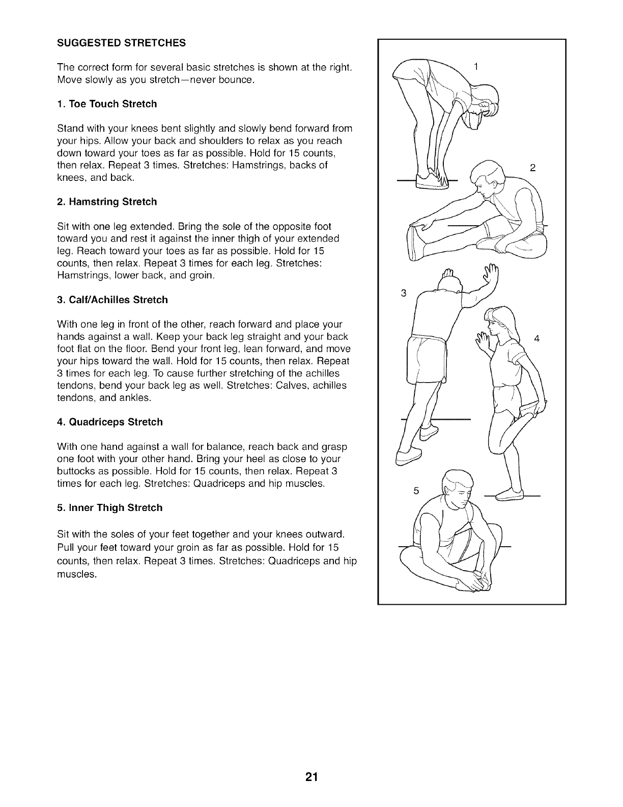
SUGGESTED STRETCHES
The correct form for several basic stretches is shown at the right.
Move slowly as you stretch--never bounce.
1. Toe Touch Stretch
Stand with your knees bent slightly and slowly bend forward from
your hips. Allow your back and shoulders to relax as you reach
down toward your toes as far as possible. Hold for 15 counts,
then relax. Repeat 3 times. Stretches: Hamstrings, backs of
knees, and back.
2. Hamstring Stretch
Sit with one leg extended. Bring the sole of the opposite foot
toward you and rest it against the inner thigh of your extended
leg. Reach toward your toes as far as possible. Hold for 15
counts, then relax. Repeat 3 times for each leg. Stretches:
Hamstrings, lower back, and groin.
3. Calf/Achilles Stretch
With one leg in front of the other, reach forward and place your
hands against a wall. Keep your back leg straight and your back
foot flat on the floor. Bend your front leg, lean forward, and move
your hips toward the wall. Hold for 15 counts, then relax. Repeat
3 times for each leg. To cause further stretching of the achilles
tendons, bend your back leg as well. Stretches: Calves, achilles
tendons, and ankles.
4. Quadriceps Stretch
With one hand against a wall for balance, reach back and grasp
one foot with your other hand. Bring your heel as close to your
buttocks as possible. Hold for 15 counts, then relax. Repeat 3
times for each leg. Stretches: Quadriceps and hip muscles.
5. Inner Thigh Stretch
Sit with the soles of your feet together and your knees outward.
Pull your feet toward your groin as far as possible. Hold for 15
counts, then relax. Repeat 3 times. Stretches: Quadriceps and hip
muscles.
5
21
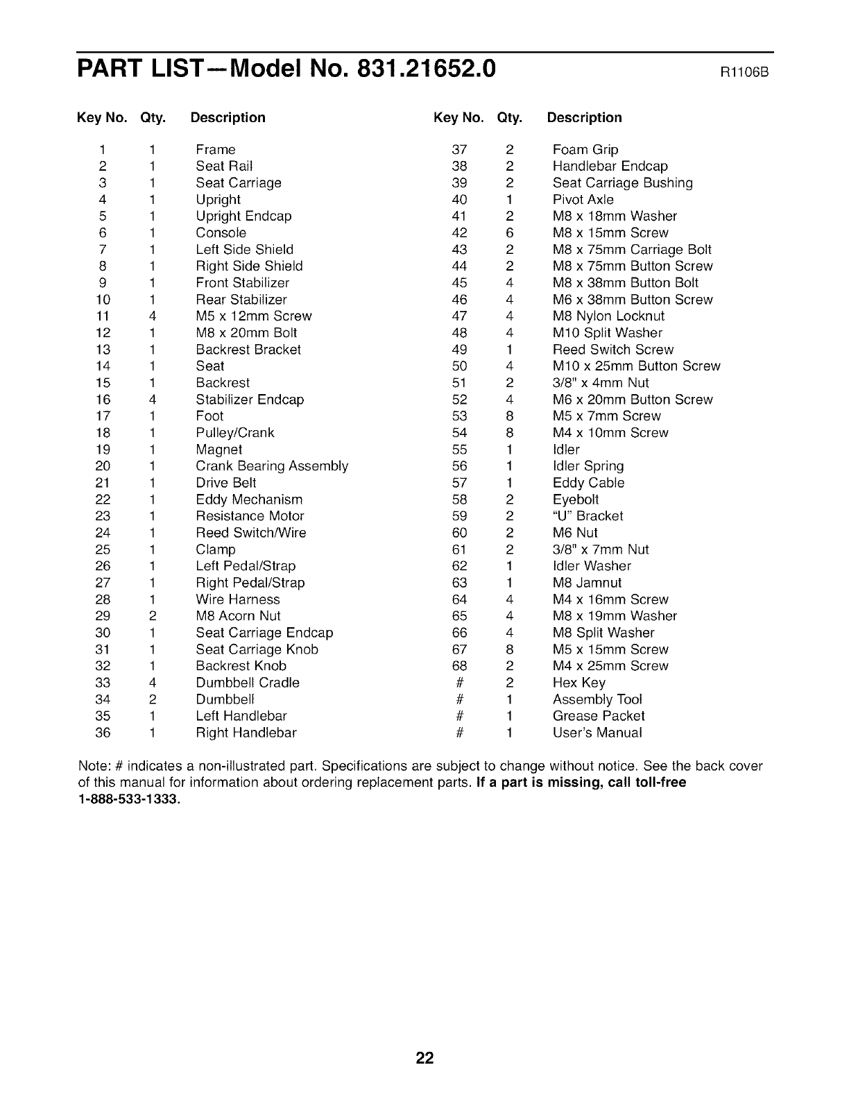
PART LIST--Model No. 831.21652.0 Rl106B
Key No. Qty, Description Key No. Qty. Description
1 1 Frame 37 2 Foam Grip
2 1 Seat Rail 38 2 Handlebar Endcap
3 1 Seat Carriage 39 2 Seat Carriage Bushing
4 1 Upright 40 1 Pivot Axle
5 1 Upright Endcap 41 2 M8 x 18mm Washer
6 1 Console 42 6 M8 x 15mm Screw
7 1 Left Side Shield 43 2 M8 x 75mm Carriage Bolt
8 1 Right Side Shield 44 2 M8 x 75mm Button Screw
9 1 Front Stabilizer 45 4 M8 x 38mm Button Bolt
10 1 Rear Stabilizer 46 4 M6 x 38mm Button Screw
11 4 M5 x 12mm Screw 47 4 M8 Nylon Locknut
12 1 M8 x 20mm Bolt 48 4 M10 Split Washer
13 1 Backrest Bracket 49 1 Reed Switch Screw
14 1 Seat 50 4 M10 x 25mm Button Screw
15 1 Backrest 51 2 3/8" x 4mm Nut
16 4 Stabilizer Endcap 52 4 M6 x 20mm Button Screw
17 1 Foot 53 8 M5 x 7mm Screw
18 1 Pulley/Crank 54 8 M4 x 10mm Screw
19 1 Magnet 55 1 Idler
20 1 Crank Bearing Assembly 56 1 Idler Spring
21 1 Drive Belt 57 1 Eddy Cable
22 1 Eddy Mechanism 58 2 Eyebolt
23 1 Resistance Motor 59 2 "U" Bracket
24 1 Reed Switch/Wire 60 2 M6 Nut
25 1 Clamp 61 2 3/8" x 7mm Nut
26 1 Left Pedal/Strap 62 1 Idler Washer
27 1 Right Pedal/Strap 63 1 M8 Jamnut
28 1 Wire Harness 64 4 M4 x 16mm Screw
29 2 M8 Acorn Nut 65 4 M8 x 19mm Washer
30 1 Seat Carriage Endcap 66 4 M8 Split Washer
31 1 Seat Carriage Knob 67 8 M5 x 15mm Screw
32 1 Backrest Knob 68 2 M4 x 25mm Screw
33 4 Dumbbell Cradle # 2 Hex Key
34 2 Dumbbell # 1 Assembly Tool
35 1 Left Handlebar # 1 Grease Packet
36 1 Right Handlebar # 1 User's Manual
Note: # indicates a non-illustrated part. Specifications are subject to change without notice. See the back cover
of this manual for information about ordering replacement parts. If a part is missing, call toll-free
1-888-533-1333.
22
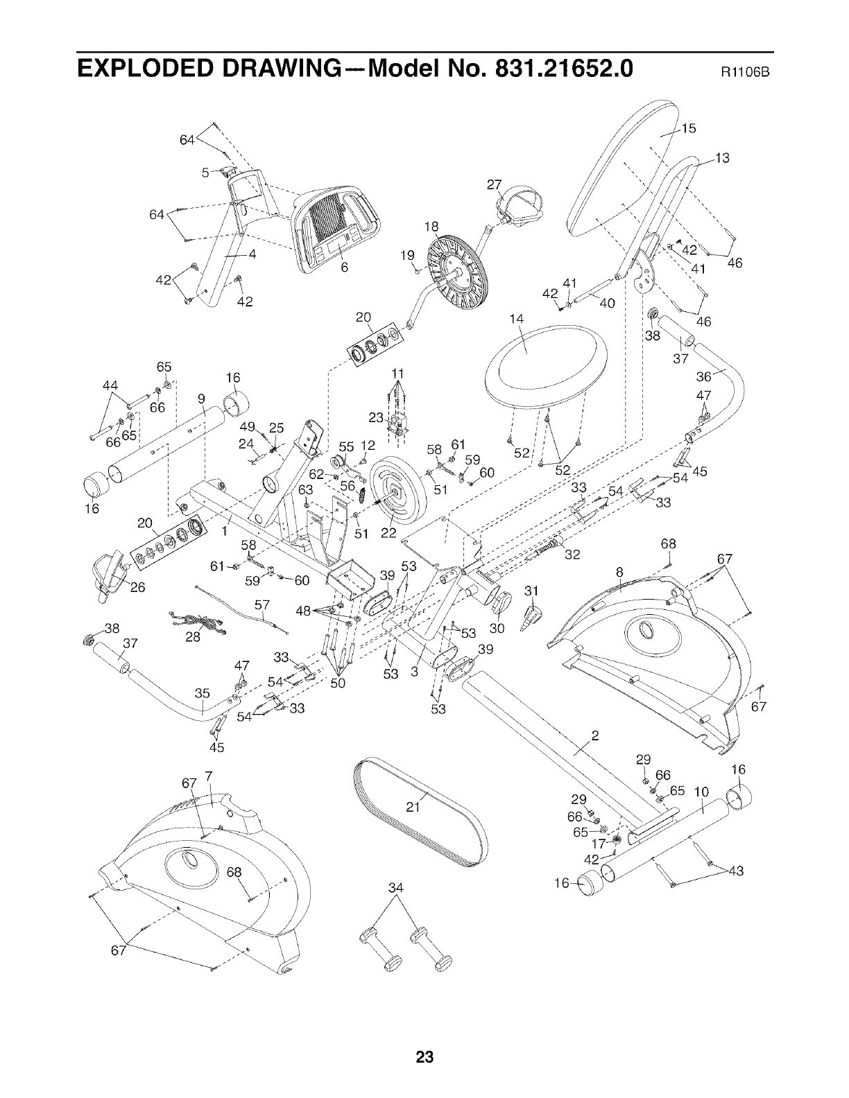
EXPLODED DRAWING--Model No. 831.21652.0 R1106B
42_
42
44
65 16
16 20
37
47
45
7
67
18
19
6
51 22
53
-' 50
34
27
30
39
29
66%
6517 _ (
42-
29 66 16
10
1"
67
23

,iiiiiiiiiiii_
iiiiiiiiiiiiii_
Your Home
For repair--in your home--of all major brand appliances, lawn and garden equipment,
or heating and cooling systems, no matter who made it, no matter who sold it!
For the replacement parts, accessories, and user's manuals that you need to do-it-yourself.
For Sears professional installation of home appliances
and items like garage door openers and water heaters.
1-800-4-MY-HOM E®(1-800-469-4663)
Call anytime, day or night (U.S.A. and Canada)
www.sears.com www.sears.ca
Our Home
For repair of carry-in items like vacuums, lawn equipment,
and electronics, call or go on-line for the location of your nearest
Sears Parts & Repair Center.
1-800-488-1222 Call anytime, day or night (U.S.A. only)
www.sears.com
To purchase a protection agreement (U.S.A.)
or maintenance agreement (Canada) on a product serviced by Sears:
1-800-827-6655 (U.S.A.) 1-800-361-6665 (Canada)
'iiiiiiiiiiiiiiiiiiiiiiiiiii:
i,_i!iiiiiiiiiiiiiiiiiiiiiiiiiiiiiiiiiiiiiiiiiiiiiiiiiiiiiiii_il;!
iiiiiiiiiiiiii
iiiiiiiiiiiiii
iiiiiiiiiiiiii
iiiiiiiiiiiiii
iiiiiiiiiiiiii
iiiiiiiiiiiiii
iiiiiiiiiiiiii
iiiiiiiiiiiiii
Para pedir servicio de reparaci6n a domicilio, y para ordenar piezas:
1-888-SU-HOGAR _(1-888-784-6427)
eal/'S
® Registered Trademark /TMTrademark /SMService Mark of Sears Brands, LLC
® Marca Registrada /TMMarca de F_.brica /SMMarca de Servicio de Sears Brands, LLC
f
90 DAY FULL WARRANTY
f
If this Sears Bike Exerciser fails due to a defect in material or workmanship within 90 days of the date
of purchase, call 1-800-4-MY-HOME ®(1-800-469-4663) to arrange for free repair (or replacement if
repair proves impossible). There is a five year warranty on the frame.
This warranty does not apply when the Bike Exerciser is used commercially or for rental purposes.
This warranty gives you specific legal rights, and you may also have other rights which vary from state
to state.
Sears, Roebuck and Co., Hoffman Estates, IL 60179
J
Part No. 246090 R1106B Printed in China © 2006 ICON IP, Inc.
