Proform 831246451 User Manual XP 580 CROSSTRAINER Manuals And Guides L0702077
PROFORM Treadmill Manual L0702077 PROFORM Treadmill Owner's Manual, PROFORM Treadmill installation guides
User Manual: Proform 831246451 831246451 PROFORM PROFORM XP 580 CROSSTRAINER - Manuals and Guides View the owners manual for your PROFORM PROFORM XP 580 CROSSTRAINER #831246451. Home:Fitness Equipment Parts:Proform Parts:Proform PROFORM XP 580 CROSSTRAINER Manual
Open the PDF directly: View PDF ![]() .
.
Page Count: 28
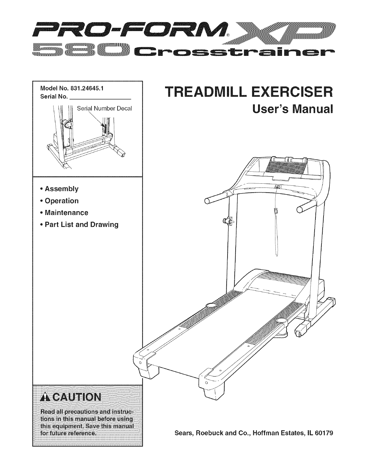
ModelNo.831.24645.1
Serial No.
Serial Number Decal
\
,Assembly
,Operation
• Maintenance
, Part List and Drawing
TR LL EXERClS
User's Manual
Sears, Roebuck and Co., Hoffman Estates, IL 60179
Cross'__..rairl_r
TABLE OF CONTENTS
iMPORTANT PRECAUTIONS ................................................................ 3
BEFORE YOU BEGIN ...................................................................... 5
ASSEMBLY ............................................................................... 6
OPERATION AND ADJUSTMENT ............................................................. 9
HOW TO FOLD AND MOVE THE TREADMILL .................................................. 17
TROUBLESHOOTING ..................................................................... 18
CONDiTiONiNG GUiDELiNES ............................................................... 20
PART LIST .............................................................................. 22
EXPLODED DRAWING .................................................................... 24
ORDERING REPLACEMENT PARTS .................................................. Back Cover
WARRANTY ...................................................................... Back Cover
iMPORTANT PRECAUTIONS
WARN ING: Toreducetheriskofburns,fire,electricshock,orinjurytopersons,readthe
following important precautions and information before operating the treadmill.
1. it Jsthe responsibility of the owner to ensure
that all users of this treadmill are adequately
informed of aiJ warnings and precautions.
2. Use the treadmill only as described.
,Place the treadmill on aJevel surface, with at
least eight feet of clearance behind it and two
feet on each side. Do not place the treadmill
on any surface that bJocks air openings. To
protect the floor or carpet from damage, place
a mat under the treadmill.
4. Keep the treadmill indoors, away from mois-
ture and dust. Do not put the treadmill in a
garage or covered patio, or near water.
5. Do not operate the treadmill where aerosol
products are used or where oxygen is being
administered.
6. Keep children under the age of 12 and pets
away from the treadmill at all times.
7. The treadmilJ should be used only by persons
weighing 300 pounds or less.
8. Never allow more than one person on the
treadmill at a time.
9. Wear appropriate exercise clothes when
using the treadmilJ. Do not wear loose clothes
that could become caught in the treadmill.
Athletic support clothes are recommended for
both men and women. A/ways wear athletic
shoes. Never use the treadmillwithbare feet,
wearing only stockings,or in sandals.
10. When connecting the power cord (see page
9), plug the power cord into a surge suppres-
sor (not included) and plug the surge sup-
pressor into a grounded circuit capabJe of
carrying 15 or more amps. No other appliance
should be on the same circuit. Do not use an
extension cord.
11. Use only a single-outlet surge suppressor that
meets all of the specifications described on
page 9. To purchase a surge suppressor, see
your local Sears store or calJ 1-800-366-7278
and order part number 146148, or see your
Jocal electronics store.
12. Failure to use aproperly functioning surge
suppressor could result in damage to the con-
trol system of the treadmill, if the control sys=
tern is damaged, the walking belt may change
speed, accelerate, or stop unexpectedly,
which may result in a falJ and serious injury.
13. Keep the power cord and the surge suppres-
sor away from heated surfaces.
14. Never move the walking belt while the power
is turned off. Do not operate the treadmill Jf
the power cord or plug is damaged, or if the
treadmill is not working properly. (See TROU-
BLESHOOTING on page 18 if the treadmiJJ is
not working properly.)
15. Read, understand, and test the emergency
stop procedure before using the treadmiJl (see
HOW TO TURN ON THE POWER on page !1).
16. Never start the treadmill while you are stand-
ing on the walking belt. Always hold the
handrails while using the treadmill.
17. The treadmill is capable of high speeds.
Adjust the speed in smalJ increments to avoid
sudden jumps in speed.
18. The pulse sensor is not a medical device.
Various factors, including the user's move-
ment, may affect the accuracy of heart rate
readings. The pulse sensor is intended only
as an exercise aid in determining heart rate
trends in general.
19. Use the included dumbbelJs only as de-
scribed in this manual. Properly store the
dumbbells in the dumbbell holders on the
console when you are not using them. if the
dumbbells are improperly stored, they may
falJ off the console, causing the user to trip.
20.Neverleave the treadmill unattended while it
is running. Always remove the key, unplug
the power cord, and switch the reset/off cir-
cuit breaker to the off position when the
treadmill is not in use. (See the drawing on
page 5 for the location of the circuit breaker.)
21. Do not attempt to raise_ lower, or move the
treadmill until it is properly assembled. (See
ASSEMBLY on page 6, and HOW TO FOLD
AND MOVE THE TREADMILL on page 17.)
You must be able to safely Jilt 45 pounds (20
kg) to raise_ lower, or move the treadmiJJ.
22. When folding or moving the treadmiJl, make
sure that the storage latch is fully closed.
24. Inspect and properly tighten all parts of the
treadmill regularly.
2s.DANG ER: Alwaysunplugthepower
cord immediately after use, before cleaning the
treadmill, and before performing the mainte=
nance and adjustment procedures described in
this manual. Never remove the motor hood un-
less instructed to do so by an authorized ser-
vice representative. Servicing other than the
procedures in this manual should be performed
by an authorized service representative only.
26. This treadmill is intended for in-home use
only. Do not use this treadmill in a commer=
cial, rental, or institutional setting.
23. Never insert any object into any opening on
the treadmill.
;'_ WARNING: Before beginning this or any exercise program, consult your physician. This
is especially important for persons over the age of 35 or persons with pre=existing health problems.
Read all instructions before using. Sears assumes no responsibility for personal injury or property
damage sustained by or through the use of this product.
SAVE THESE iNSTRUCTiONS
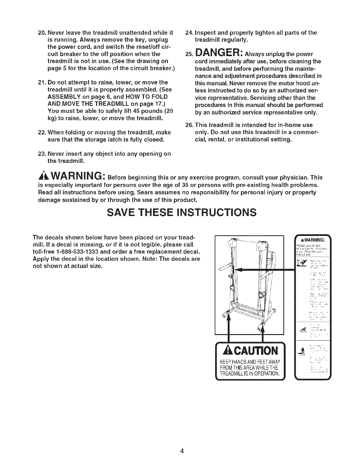
The decals shown below have been placed on your tread-
mill. If a decal is missing, or if it is not legible, please call
toll-free 1-888-533-1333 and order a free replacement decal.
Apply the decal in the location shown. Note: The decals are
not shown at actual size.
CAUTION
PHANDSANDFEETAWAY
| FROMTHiSAREA_JHILETHE
4
BEFORE YOU BEGIN
Thank you for selecting the revolutionary PROFORM ®
XP 580 CROSSTRAINER treadmill. The XP 580
CROSSTRAINER treadmill offers an impressive array
of features designed to make your workouts at home
more enjoyable and effective. And when you're not ex-
ercising, the unique XP 580 CROSSTRAINER tread-
mill can be folded up, requiring less than half the floor
space of other treadmills.
For your benefit, read this manual carefully before
using the treadmill. If you have questions after read-
ing this manual, call 1-800-4-MY-HOME ®(1-800-469-
4663).To help us assist you, please note the product
model number and serial number before calling. The
model number of the treadmill is 831.24645.1. The ser-
ial number can be found on a decal attached to the
treadmill (see the front cover of this manual for the lo-
cation).
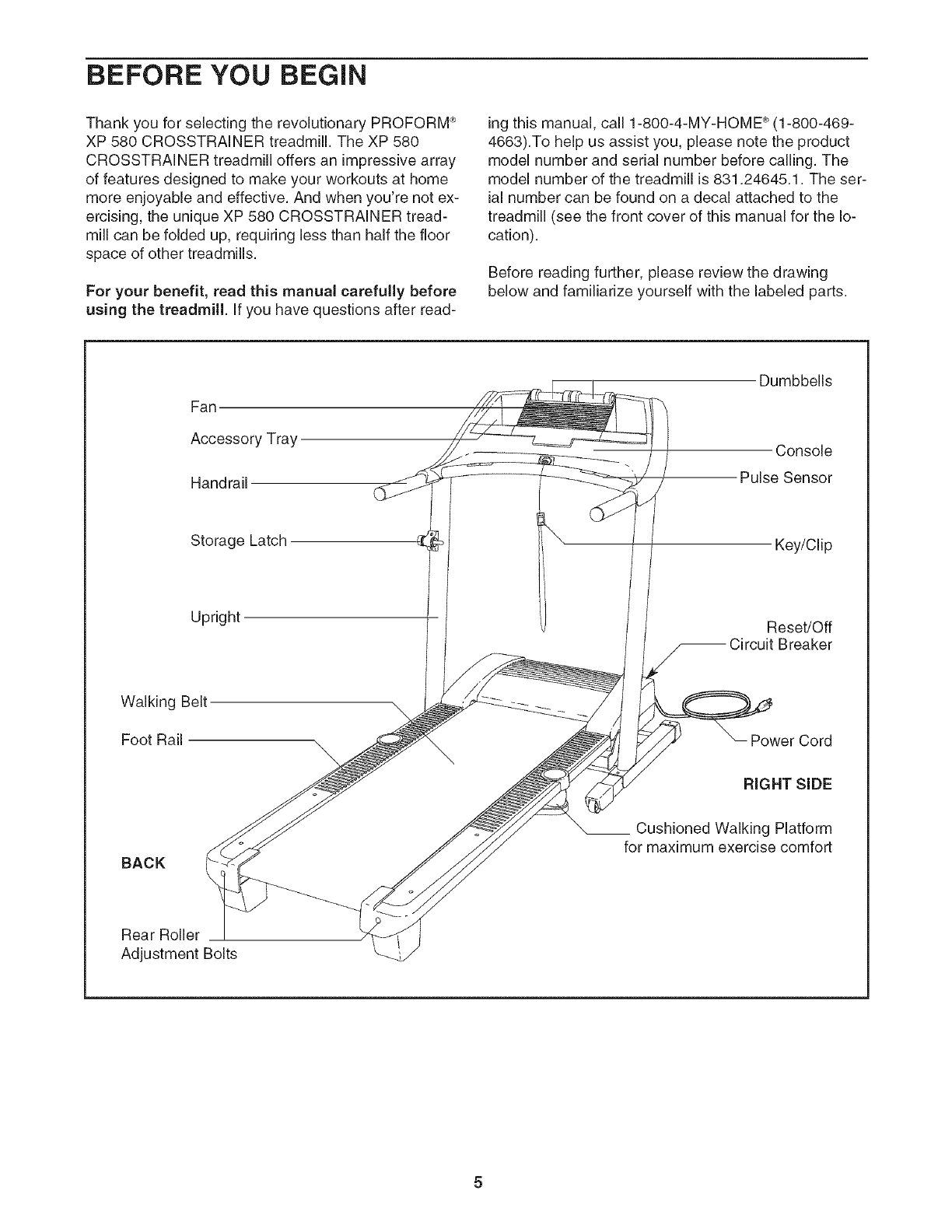
Before reading further, please review the drawing
below and familiarize yourself with the labeled parts.
Fan
Accessory Tray
Handrail
Dumbbells
Console
Pulse Sensor
Storage Latch
Upright
Key/Clip
Reset/Off
Breaker
Walking Belt
Foot Rail
BACK I
Rear Roller
Adjustment Bolts
Power Cord
RIGHT SiDE
Cushioned Walking Platform
for maximum exercise comfort
ASSEMBLY
Make sure that the power cord is unplugged. Assembly requires two persons. Set the treadmill in a cleared
area and remove all packing materials. Do not dispose of the packing materials until assembly is completed. Note:
The underside of the treadmill walking belt is coated with high-performance lubricant. During shipping, a small
amount of lubricant may be transferred to the top of the walking belt or the shipping carton. This is a normal con-
dition and does not affect treadmill performance. If there is lubricant on top of the walking belt, simply wipe off the
lubricant with a soft cloth and a mild, non-abrasive cleaner.
Assembly requires the included hex keys _ and your own phillips screwdriver (_=====_>
Use the drawings below to identify the assembly hardware. The number in parentheses below each drawing is
the key number of the part, from the PART LIST on pages 22 and 23. The number after the parentheses shows
the quantity needed for assembly. Note: If a part is not in the parts bag, check to see if it is preattached to one of
the parts to be assembled, if apart is missing, call toll=free 1=888=533=1333. To avoid damaging plastic
parts, do not use power tools for assembly.
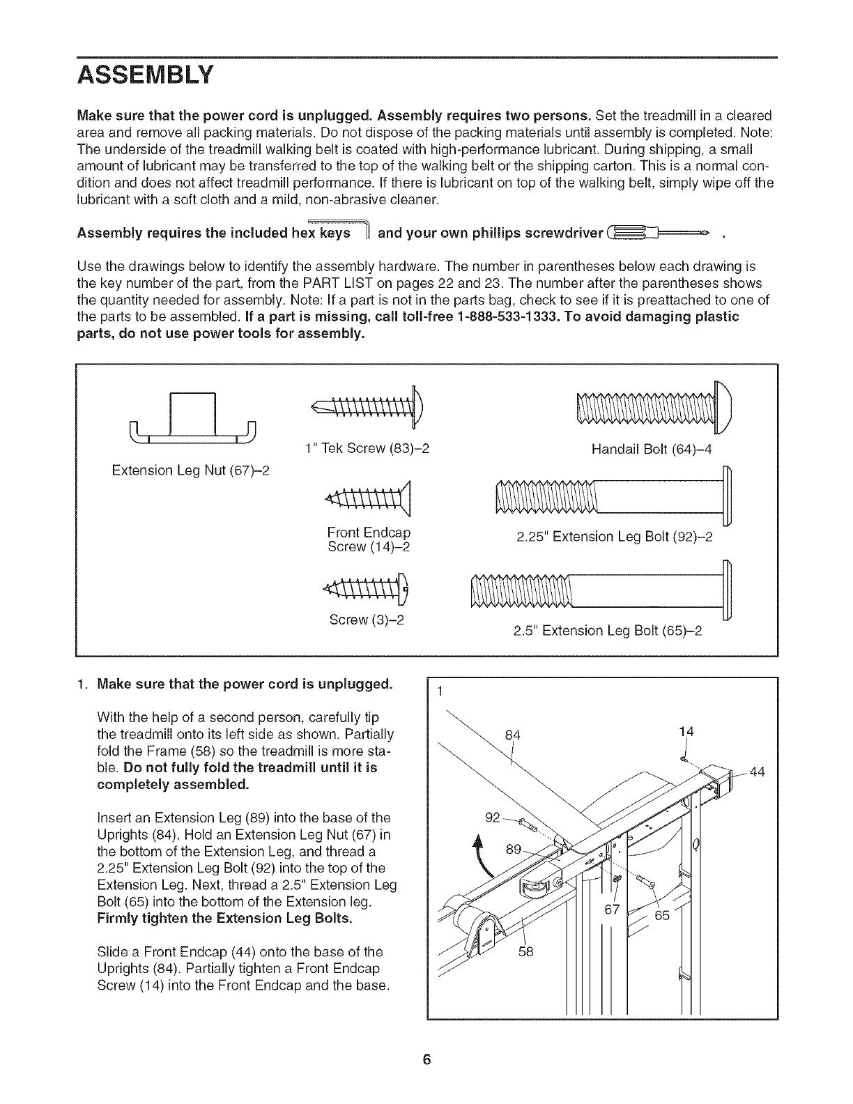
Extension Leg Nut (67)-2
1" Tek Screw (83)-2
Front Endcap
Screw (14)-2
Screw (3)-2
Handail Bolt (64)-4
2.25" Extension Leg Bolt (92)-2
2.5" Extension Leg Bolt (65)-2 D
1. Make sure that the power cord is unplugged.
With the help of a second person, carefully tip
the treadmill onto its left side as shown. Partially
fold the Frame (58) so the treadmill is more sta-
ble. Do not fully fold the treadmill until it is
completely assembled.
Insert an Extension Leg (89) into the base of the
Uprights (84). Hold an Extension Leg Nut (67) in
the bottom of the Extension Leg, and thread a
2.25" Extension Leg Bolt (92) into the top of the
Extension Leg. Next, thread a 2.5" Extension Leg
Bolt (65) into the bottom of the Extension leg.
Firmly tighten the Extension Leg Bolts.
Slide a Front Endcap (44) onto the base of the
Uprights (84). Partially tighten a Front Endcap
Screw (14) into the Front Endcap and the base.
84
58
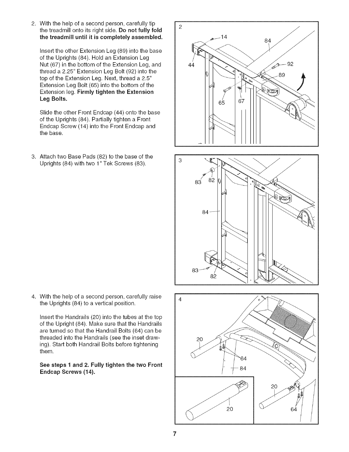
2. 2
Withthehelpofa secondperson,carefullytip
thetreadmillontoitsrightside.Donotfullyfold
thetreadmilluntil it is completely assembled.
Insert the other Extension Leg (89) into the base
of the Uprights (84). Hold an Extension Leg
Nut (67) in the bottom of the Extension Leg, and
thread a 2.25" Extension Leg Bolt (92) into the
top of the Extension Leg. Next, thread a 2.5"
Extension Leg Bolt (65) into the bottom of the
Extension leg. Firmly tighten the Extension
Leg Bolts.
Slide the other Front Endcap (44) onto the base
of the Uprights (84). Partially tighten a Front
Endcap Screw (14) into the Front Endcap and
the base.
44
84
Attach two Base Pads (82) to the base of the
Uprights (84) with two 1" Tek Screws (83).
With the help of a second person, carefully raise
the Uprights (84) to a vertical position.
Insert the Handrails (20) into the tubes at the top
of the Upright (84). Make sure that the Handrails
are turned so that the Handrail Bolts (64) can be
threaded into the Handrails (see the inset draw-
ing). Start both Handrail Bolts before tightening
them.
See steps 1 and 2. Fully tighten the two Front
Endcap Screws (14).
20
20
2O
64
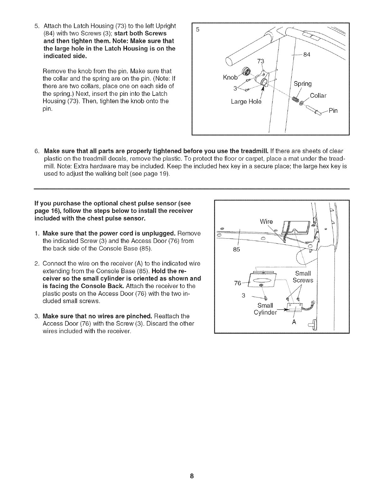
5. 5
AttachtheLatchHousing(73)totheleftUpright
(84)withtwoScrews(3);startbothScrews
andthentightenthem.Note:Makesurethat
thelarge hole in the Latch Housing is on the
indicated side.
Remove the knob from the pin. Make sure that
the collar and the spring are on the pin. (Note: If
there are two collars, place one on each side of
the spring.) Next, insert the pin into the Latch
Housing (73). Then, tighten the knob onto the
pin. Large
Spring
Collar
Make sure that all parts are properly tightened before you use the treadmill. If there are sheets of clear
plastic on the treadmill decals, remove the plastic. To protect the floor or carpet, place a mat under the tread-
mill. Note: Extra hardware may be included. Keep the included hex key in a secure place; the large hex key is
used to adjust the walking belt (see page 19).
if you purchase the optional chest pulse sensor (see
page 16), follow the steps below to install the receiver
included with the chest pulse sensor.
1. Make sure that the power cord is unplugged. Remove
the indicated Screw (3) and the Access Door (76) from
the back side of the Console Base (85).
2. Connect the wire on the receiver (A) to the indicated wire
extending from the Console Base (85). Hold the re-
ceiver so the small cylinder is oriented as shown and
is facing the Console Back. Attach the receiver to the
plastic posts on the Access Door (76) with the two in-
cluded small screws.
3. Make sure that no wires are pinched. Reattach the
Access Door (76) with the Screw (3). Discard the other
wires included with the receiver.
Wire
s a, r
Cylinder _ --c_
8
OPERATION AND ADJUSTMENT
THE PRE=LUBRICATED WALKING BELT
Your treadmill features a walking belt coated with high-
performance lubricant, iMPORTANT: Never apply sil-
icone spray or other substances to the walking
belt or the walking platform. Such substances will
deteriorate the walking belt and cause excessive
wear.
HOW TO PLUG IN THE POWER CORD
an equipment-grounding conductor and a grounding
plug. Plug the power cord into asurge suppressor,
and plug the surge suppressor into an appropriate
outlet that is properly installed and grounded in
accordance with all local codes and ordinances.
Important: The treadmill is not compatible with
GFCl=equipped outlets.
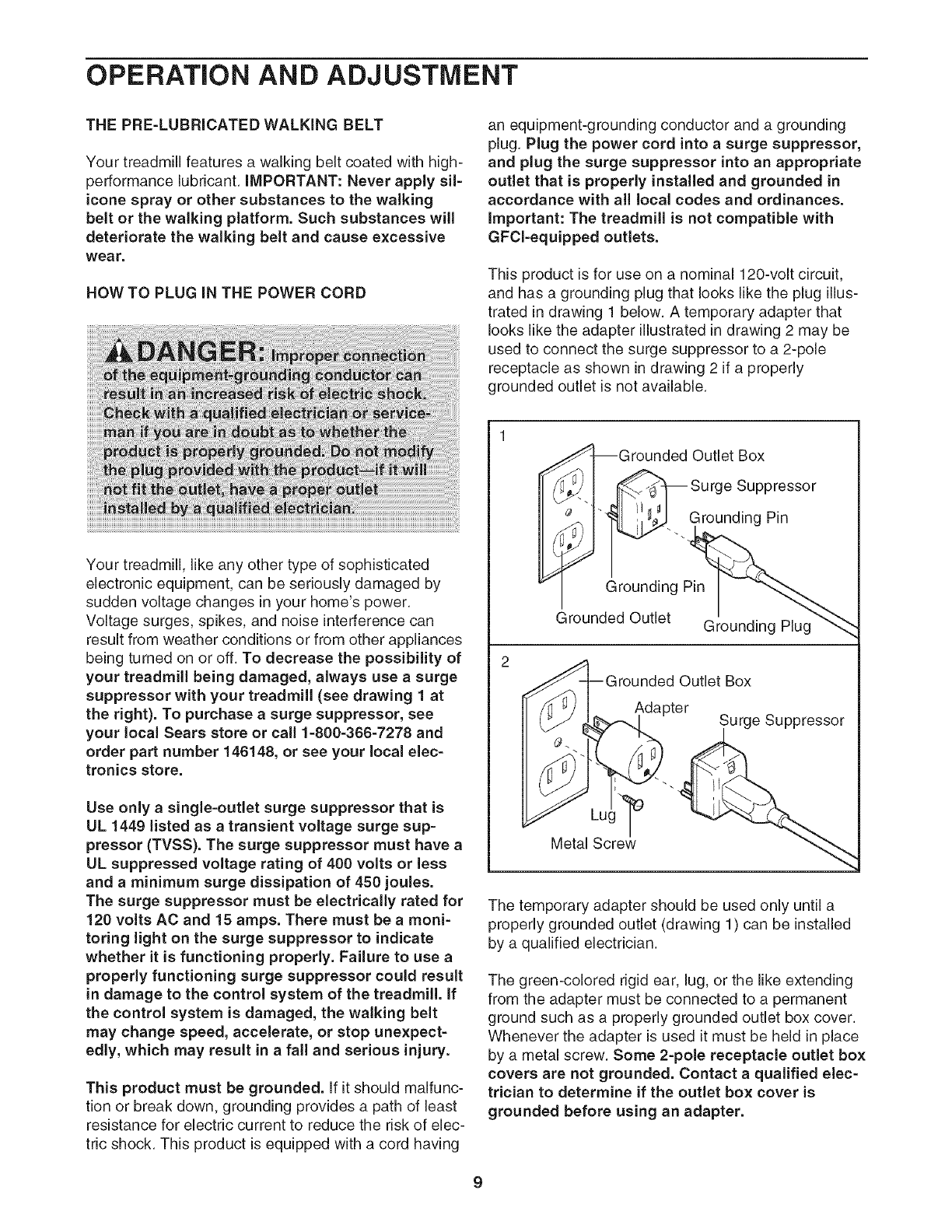
This product is for use on a nominal 120-volt circuit,
and has a grounding plug that looks like the plug illus-
trated in drawing 1 below. A temporary adapter that
looks like the adapter illustrated in drawing 2 may be
used to connect the surge suppressor to a 2-pole
receptacle as shown in drawing 2 if a properly
grounded outlet is not available.
Your treadmill, like any other type of sophisticated
electronic equipment, can be seriously damaged by
sudden voltage changes in your home's power.
Voltage surges, spikes, and noise interference can
result from weather conditions or from other appliances
being turned on or off. To decrease the possibility of
your treadmill being damaged, always use a surge
suppressor with your treadmill (see drawing 1 at
the right). To purchase asurge suppressor, see
your local Sears store or call 1=800=366=7278 and
order part number 146148, or see your local elec=
tronics store.
Use only a single-outlet surge suppressor that is
UL 1449 listed as a transient voltage surge sup=
pressor (TVSS). The surge suppressor must have a
UL suppressed voltage rating of 400 volts or less
and a minimum surge dissipation of 450 joules.
The surge suppressor must be electrically rated for
120 volts AC and 15 amps. There must be amoni=
toting light on the surge suppressor to indicate
whether it is functioning properly. Failure to use a
properly functioning surge suppressor could result
in damage to the control system of the treadmill, if
the control system is damaged, the walking belt
may change speed, accelerate, or stop unexpect=
edly, which may result in a fall and serious injury.
This product must be grounded. If it should malfunc-
tion or break down, grounding provides a path of least
resistance for electric current to reduce the risk of elec-
tric shock. This product is equipped with a cord having
IGrounded Outlet Box
_.._ -- Surge Suppressor
_'< "-. Grounding Pin
Grounding Pin
_rounded Outlet Grounding Plug
2
_rounded Outlet Box
Adapter Surge Suppressor
Metal Screw_ "
The temporary adapter should be used only until a
properly grounded outlet (drawing 1) can be installed
by a qualified electrician.
The green-colored rigid ear, lug, or the like extending
from the adapter must be connected to a permanent
ground such as a properly grounded outlet box cover.
Whenever the adapter is used it must be held in place
by a metal screw. Some 2=pole receptacle outlet box
covers are not grounded. Contact a qualified elec=
trician to determine if the outlet box cover is
grounded before using an adapter.
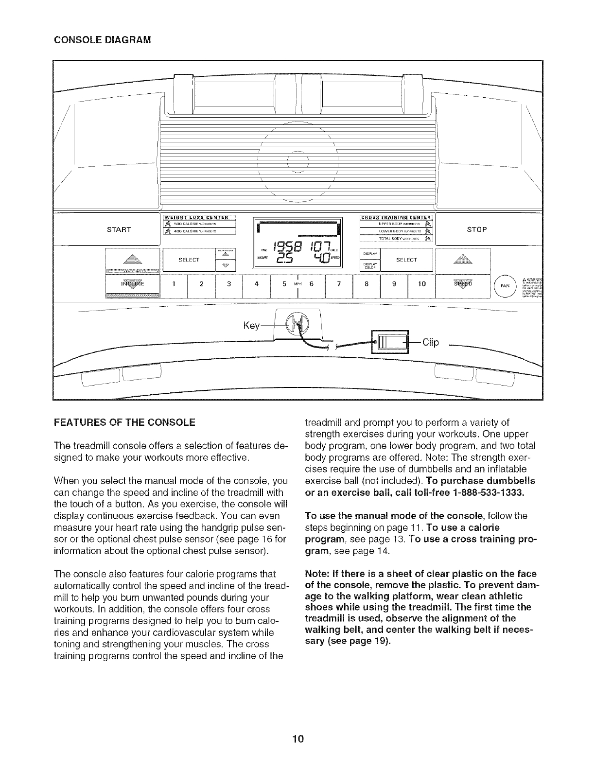
CONSOLEDIAGRAM
/
I
START
_ 5o0 CALOI_WO_KOUlS
.€_ 4OO CALOriEW,,R_,]L_TS
SELECT
1 2
j .......
7
/x
J[/ I
\/
\/
\ 7
........... J
i _____j
I£'5B
2.5 4.0
I
3 4 5 M_ 6 7
I
I
_0WER 800¥ we_c_u,s _l
8 9 t0
STOP
'\\\\\
\\\
\\
r¢6 eris I
FEATURES OF THE CONSOLE
The treadmill console offers a selection of features de-
signed to make your workouts more effective.
When you select the manual mode of the console, you
can change the speed and incline of the treadmill with
the touch of a button. As you exercise, the console will
display continuous exercise feedback. You can even
measure your heart rate using the handgrip pulse sen-
sor or the optional chest pulse sensor (see page 16 for
information about the optional chest pulse sensor).
The console also features four calorie programs that
automatically control the speed and incline of the tread-
mill to help you burn unwanted pounds during your
workouts. In addition, the console offers four cross
training programs designed to help you to burn calo-
ries and enhance your cardiovascular system while
toning and strengthening your muscles. The cross
training programs control the speed and incline of the
treadmill and prompt you to perform a variety of
strength exercises during your workouts. One upper
body program, one lower body program, and two total
body programs are offered. Note: The strength exer-
cises require the use of dumbbells and an inflatable
exercise ball (not included). To purchase dumbbells
or an exercise ball, call toll-free 1-888-533-1333.
To use the manual mode of the console, follow the
steps beginning on page 11. To use a calode
program, see page 13. To use a cross training pro-
gram, see page 14.
Note: If there is a sheet of clear plastic on the face
of the console, remove the plastic. To prevent dam=
age to the walking platform, wear clean athletic
shoes while using the treadmill. The first time the
treadmill is used, observe the alignment of the
walking belt, and center the walking belt if neces=
sary (see page 19).
10
HOW TO TURN ON THE POWER
Plug in the power cord (see page 9).
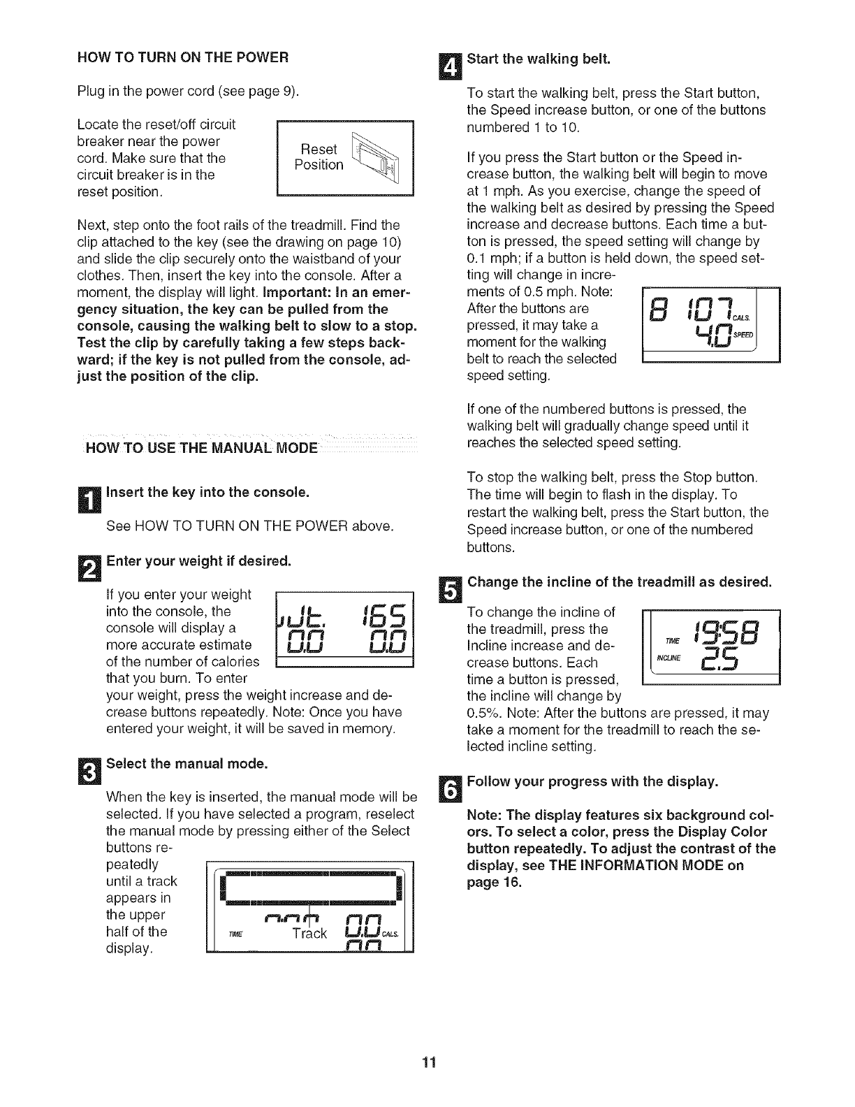
Locate the reset/off circuit
breaker near the power
cord. Make sure that the
circuit breaker is in the
reset position.
Reset
Position
Next, step onto the foot rails of the treadmill. Find the
clip attached to the key (see the drawing on page 10)
and slide the clip securely onto the waistband of your
clothes. Then, insert the key into the console. After a
moment, the display will light. Important: In an emer-
gency situation, the key can be pulled from the
console, causing the walking belt to slow to astop.
Test the clip by carefully taking afew steps back=
ward; if the key is not pulled from the console, ad=
just the position of the clip.
HOWTO USETHE MANUALMODE i
Insert the key into the console.
See HOW TO TURN ON THE POWER above.
Enter your weight if desired.
If you enter your weight
into the console, the
console will display a
more accurate estimate
of the number of calories
that you burn. To enter
,db. 165
t'3f=3 1"11"1
LJ.LJ U.U
your weight, press the weight increase and de-
crease buttons repeatedly. Note: Once you have
entered your weight, it will be saved in memory.
Select the manual mode.
When the key is inserted, the manual mode will be
selected. If you have selected a program, reselect
the manual mode by pressing either of the Select
buttons re-
peatedly
until a track
appears in
the upper
half of the
display.
Ir¢"---""--"1]
I_u m_m ml
I
Start the walking belt.
To start the walking belt, press the Start button,
the Speed increase button, or one of the buttons
numbered 1 to 10.
If you press the Start button or the Speed in-
crease button, the walking belt will begin to move
at 1 mph. As you exercise, change the speed of
the walking belt as desired by pressing the Speed
increase and decrease buttons. Each time a but-
ton is pressed, the speed setting will change by
0.1 mph; if a button is held down, the speed set-
ting will change in incre-
ments of 0.5 mph. Note:
After the buttons are
pressed, it may take a
moment for the walking
belt to reach the selected
speed setting.
BIHmO SPEED!
If one of the numbered buttons is pressed, the
walking belt will gradually change speed until it
reaches the selected speed setting.
To stop the walking belt, press the Stop button.
The time will begin to flash in the display. To
restart the walking belt, press the Start button, the
Speed increase button, or one of the numbered
buttons.
Change the incline of the treadmill as desired.
To change the incline of I [
the treadmill, press the ' _5 B
Incline increase and de- T,_ 1
crease buttons. Each ,NCU_E_,_
time a button is pressed,
the incline will change by
0.5%. Note: After the buttons are pressed, it may
take a moment for the treadmill to reach the se-
lected incline setting.
Follow your progress with the display.
Note: The display features six background col=
ors. To select a color, press the Display Color
button repeatedly. To adjust the contrast of the
display, see THE iNFORMATiON MODE on
page 16.
11
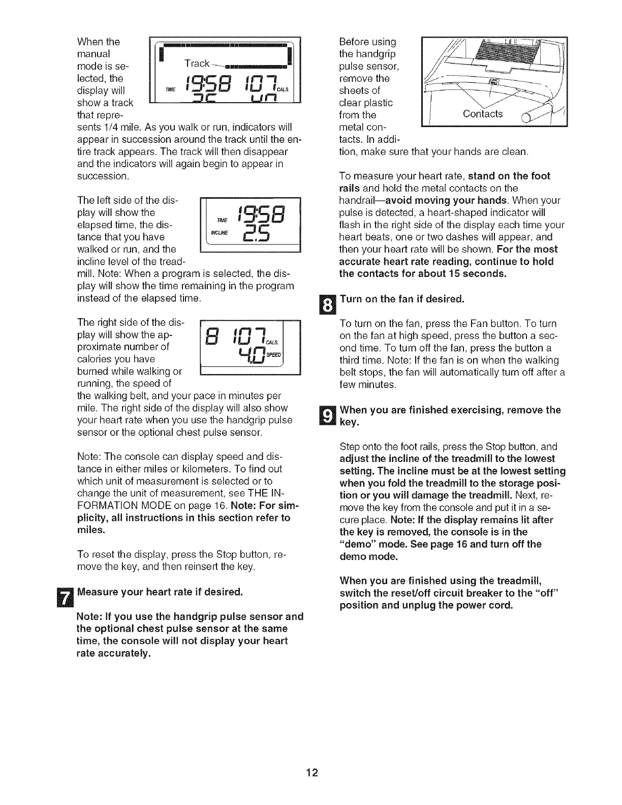
When the
manual
mode is se-
lected, the
display will
show a track
that repre-
Track ---_,..,,,_,,,,
,,ME19"5B IOlo Ls
_C" LIt_ [
sents 1/4 mile. As you walk or run, indicators will
appear in succession around the track until the en-
tire track appears. The track will then disappear
and the indicators will again begin to appear in
succession.
Theeftsdeo,theds1[
play will show the _lql:_ _::_
elapsed time, the dis- _ME
tance that you have _CuNE
walked or run, and the
incline level of the tread-
mill. Note: When a program is selected, the dis-
play will show the time remaining in the program
instead of the elapsed time.
The right side of the dis- lrBmtt_ !
play will show the ap- __ "l I
JU ICALS.I
proximate number of
calories you have "I.Lj s_E_
burned while walking or
running, the speed of
the walking belt, and your pace in minutes per
mile. The right side of the display will also show
your heart rate when you use the handgrip pulse
sensor or the optional chest pulse sensor.
Note: The console can display speed and dis-
tance in either miles or kilometers. To find out
which unit of measurement is selected or to
change the unit of measurement, see THE IN-
FORMATION MODE on page 16. Note: For sim-
plicity, all instructions in this section refer to
miles.
To reset the display, press the Stop button, re-
move the key, and then reinsert the key.
Measure your heart rate if desired.
Note: if you use the handgrip pulse sensor and
the optional chest pulse sensor at the same
time, the console will not display your heart
rate accurately.
Before using
the handgrip
pulse sensor,
remove the
sheets of
clear plastic
from the Contacts
metal con-
tacts. In addi-
tion, make sure that your hands are clean.
To measure your heart rate, stand on the foot
rails and hold the metal contacts on the
handrail--avoid moving your hands. When your
pulse is detected, a heart-shaped indicator will
flash in the right side of the display each time your
heart beats, one or two dashes will appear, and
then your heart rate will be shown. For the most
accurate heart rate reading, continue to hold
the contacts for about 15 seconds.
Turn on the fan if desired.
To turn on the fan, press the Fan button. To turn
on the fan at high speed, press the button a sec-
ond time. To turn off the fan, press the button a
third time. Note: If the fan is on when the walking
belt stops, the fan will automatically turn off after a
few minutes.
When you are finished exercising, remove the
key.
Step onto the foot rails, press the Stop button, and
adjust the incline of the treadmill to the lowest
setting. The incline must be at the lowest setting
when you fold the treadmill to the storage posi-
tion or you will damage the treadmill. Next, re-
move the key from the console and put it in a se-
cure place. Note: if the display remains lit after
the key is removed, the console is in the
"demo" mode. See page 16 and turn off the
demo mode.
When you are finished using the treadmill,
switch the resetJoff circuit breaker to the "off"
position and unplug the power cord.
12
HOW TO USE ACALORIE PROGRAM
insert the key into the console.
See HOW TO TURN ON THE POWER on page
11.
Enter your weight.
See step 2 on page 11. Note: Always enter your
weight before using acalorie program; the
speed and incline settings of the program will
depend on the weight setting that you enter.
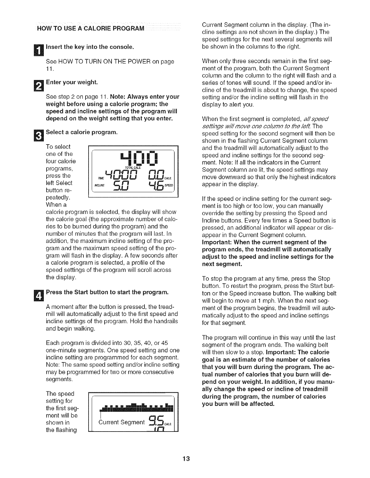
Select a calorie program.
To select
one of the
four calorie
programs,
press the
left Select
button re-
peatedly.
When a
'-"-'0 ]
o,HO: O O.O0,,,/
,,0,,,5.0
calorie program is selected, the display will show
the calorie goal (the approximate number of calo-
ries to be burned during the program) and the
number of minutes that the program will last. In
addition, the maximum incline setting of the pro-
gram and the maximum speed setting of the pro-
gram will flash in the display. A few seconds after
a calorie program is selected, a profile of the
speed settings of the program will scroll across
the display.
Press the Start button to start the program.
A moment after the button is pressed, the tread-
mill will automatically adjust to the first speed and
incline settings of the program. Hold the handrails
and begin walking.
Each program is divided into 30, 35, 40, or 45
one-minute segments. One speed setting and one
incline setting are programmed for each segment.
Note: The same speed setting and/or incline setting
may be programmed for two or more consecutive
segments.
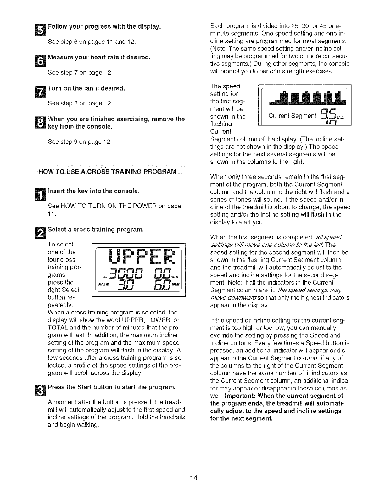
The speed
setting for
the first seg-
ment will be
shown in
the flashing c,u l
Current Segment column in the display. (The in-
cline settings are not shown in the display.) The
speed settings for the next several segments will
be shown in the columns to the right.
When only three seconds remain in the first seg-
ment of the program, both the Current Segment
column and the column to the right will flash and a
series of tones will sound. If the speed and/or in-
cline of the treadmill is about to change, the speed
setting and/or the incline setting will flash in the
display to alert you.
When the first segment is completed, a//speed'
seUings wi// move one co/drafT to the/eft. The
speed setting for the second segment will then be
shown in the flashing Current Segment column
and the treadmill will automatically adjust to the
speed and incline settings for the second seg-
ment. Note: If all the indicators in the Current
Segment column are lit, the speed settings may
move downward so that only the highest indicators
appear in the display.
If the speed or incline setting for the current seg-
ment is too high or too low, you can manually
override the setting by pressing the Speed and
Incline buttons. Every few times a Speed button is
pressed, an additional indicator will appear or dis-
appear in the Current Segment column.
important: When the current segment of the
program ends, the treadmill will automatically
adjust to the speed and incline settings for the
next segment.
To stop the program at any time, press the Stop
button. To restart the program, press the Start but-
ton or the Speed increase button. The walking belt
will begin to move at 1 mph. When the next seg-
ment of the program begins, the treadmill will auto-
matically adjust to the speed and incline settings
for that segment.
The program will continue in this way until the last
segment of the program ends. The walking belt
will then slow to a stop. Important: The calorie
goal is an estimate of the number of calories
that you will burn during the program. The ac=
tual number of calories that you burn will de=
pend on your weight, in addition, if you manu=
ally change the speed or incline of treadmill
during the program, the number of calories
you burn will be affected.
13
Follow your progress with the display.
See step 6 on pages 11 and 12.
Measure your heart rate if desired.
See step 7 on page 12.
Turn on the fan if desired.
See step 8 on page 12.
When you are finished exercising, remove the
key from the console.
See step 9 on page 12.
HOW TO USE ACROSS TRAINING PROGRAM
Insert the key into the console.
See HOW TO TURN ON THE POWER on page
11.
Select a cross training program.
To select
one of the
four cross
training pro-
grams,
press the
right Select
button re-
peatedly.
| =1"= Ir'l r" Ir-|
| it- |" Ir-
m [] [] ram• [] []
__ t=3,¢3 t=i £3t=1
_ME.._ U'U U U,U _Ls.
,'-o' 9.0 6.0
When a cross training program is selected, the
display will show the word UPPER, LOWER, or
TOTAL and the number of minutes that the pro-
gram will last. In addition, the maximum incline
setting of the program and the maximum speed
setting of the program will flash in the display. A
few seconds after a cross training program is se-
lected, a profile of the speed settings of the pro-
gram will scroll across the display.
Press the Start button to start the program.
A moment after the button is pressed, the tread-
mill will automatically adjust to the first speed and
incline settings of the program. Hold the handrails
and begin walking.
Each program is divided into 25, 30, or 45 one-
minute segments. One speed setting and one in-
cline setting are programmed for most segments.
(Note: The same speed setting and/or incline set-
ting may be programmed for two or more consecu-
tive segments.) During other segments, the console
will prompt you to perform strength exercises.
The speed
setting for
the first seg-
ment will be
shown in the
flashing
Current
•,L []m .,_ .._, mL -m ]
m mJ l
Segment9.5oALsI
Segment column of the display. (The incline set-
tings are not shown in the display.) The speed
settings for the next several segments will be
shown in the columns to the right.
When only three seconds remain in the first seg-
ment of the program, both the Current Segment
column and the column to the right will flash and a
series of tones will sound. If the speed and/or in-
cline of the treadmill is about to change, the speed
setting and/or the incline setting will flash in the
display to alert you.
When the first segment is completed, a//speed
seLf/rigs wi// move one co/utah to the/eft. The
speed setting for the second segment will then be
shown in the flashing Current Segment column
and the treadmill will automatically adjust to the
speed and incline settings for the second seg-
ment. Note: If all the indicators in the Current
Segment column are lit, the speed/settings may
fnoy8 d'ow/Twafo'so that only the highest indicators
appear in the display.
If the speed or incline setting for the current seg-
ment is too high or too low, you can manually
override the setting by pressing the Speed and
Incline buttons. Every few times a Speed button is
pressed, an additional indicator will appear or dis-
appear in the Current Segment column; if any of
the columns to the right of the Current Segment
column have the same number of lit indicators as
the Current Segment column, an additional indica-
tor may appear or disappear in those columns as
well. Important: When the current segment of
the program ends, the treadmill will automati-
cally adjust to the speed and incline settings
for the next segment.
14
To stop the program at any time, press the Stop
button. The time will begin to flash in the display.
To restart the program, press the Start button or
the Speed increase button. The walking belt will
begin to move at 1 mph. When the next segment
of the program begins, the treadmill will automati-
cally adjust to the speed and incline settings for
that segment.
Perform the first strength exercise when
prompted.
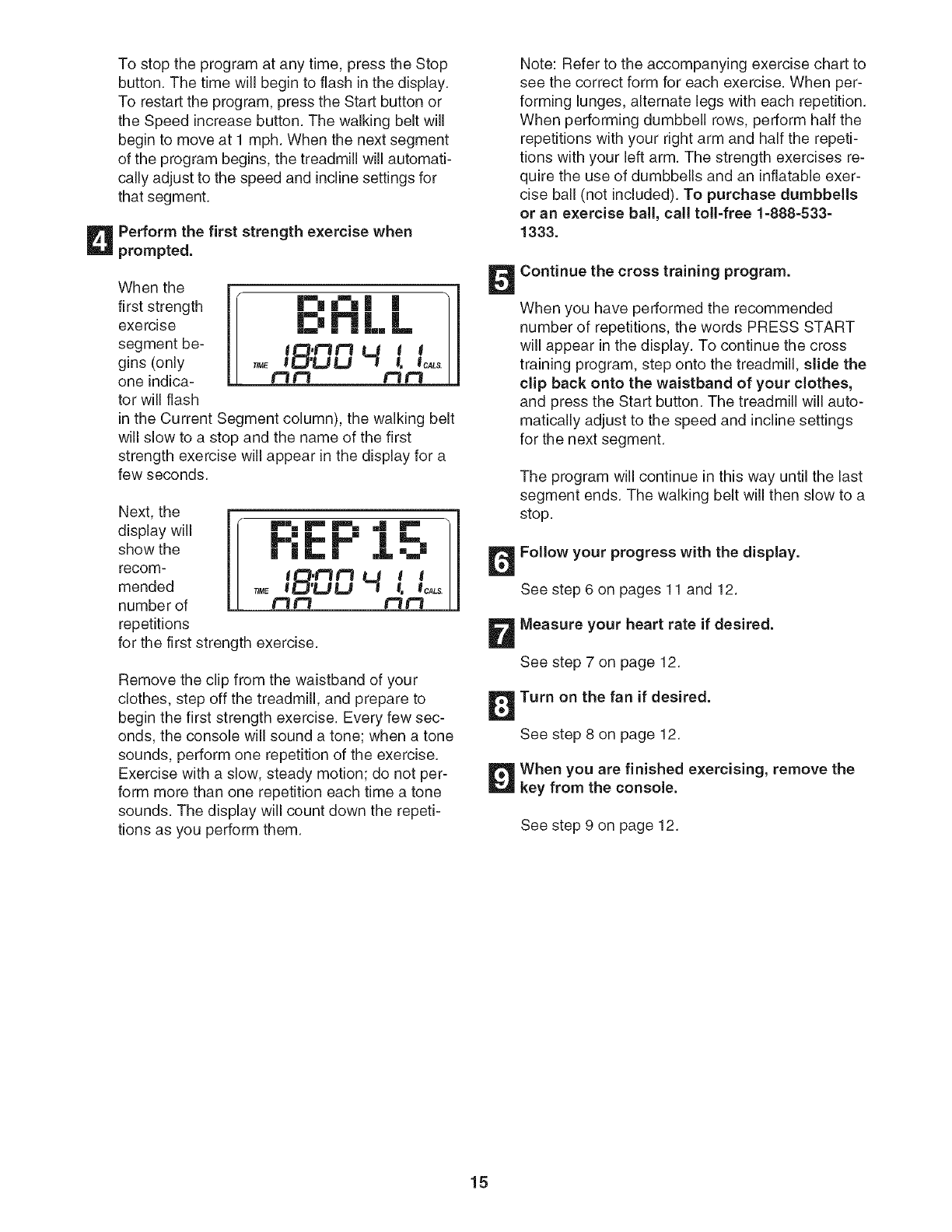
Whenthe1
first strength |m"l _ | |
exercise N L L
segment be- tl_,t'tt"=l L.J I 1
gins (only T_ !II_'LILI !, 1_.
one indica- t'=l r'I t=_t'3
tor will flash
in the Current Segment column), the walking belt
will slow to a stop and the name of the first
strength exercise will appear in the display for a
few seconds.
Next, the
display will
show the
recom-
mended
number of
repetitions
P%P"r%. ml _
m m I /
m /
I
_O"_ U I I I
I U -1 I. lolls/
for the first strength exercise.
Remove the clip from the waistband of your
clothes, step off the treadmill, and prepare to
begin the first strength exercise. Every few sec-
onds, the console will sound a tone; when a tone
sounds, perform one repetition of the exercise.
Exercise with a slow, steady motion; do not per-
form more than one repetition each time a tone
sounds. The display will count down the repeti-
tions as you perform them.
Note: Refer to the accompanying exercise chart to
see the correct form for each exercise. When per-
forming lunges, alternate legs with each repetition.
When performing dumbbell rows, perform half the
repetitions with your right arm and half the repeti-
tions with your left arm. The strength exercises re-
quire the use of dumbbells and an inflatable exer-
cise ball (not included). To purchase dumbbells
or an exercise ball, call toll-free 1-888-533-
1333.
Continue the cross training program.
When you have performed the recommended
number of repetitions, the words PRESS START
will appear in the display. To continue the cross
training program, step onto the treadmill, slide the
clip back onto the waistband of your clothes,
and press the Start button. The treadmill will auto-
matically adjust to the speed and incline settings
for the next segment.
The program will continue in this way until the last
segment ends. The walking belt will then slow to a
stop.
Follow your progress with the display.
See step 6 on pages 11 and 12.
Measure your heart rate if desired.
See step 7 on page 12.
Turn on the fan if desired.
See step 8 on page 12.
When you are finished exercising, remove the
key from the console.
See step 9 on page 12.
15
THE INFORMATION MODE
The console features an information mode that keeps
track of treadmill usage information. The information
mode also allows you to select miles or kilometers as
the unit of measurement, to adjust the contrast of the
display, and to turn on and turn off the demo mode.
To select the information mode, hold down the Stop
button, insert the key into the console, and then release
the Stop button. When the information mode is se-
lected, the following information will appear in the dis-
play:
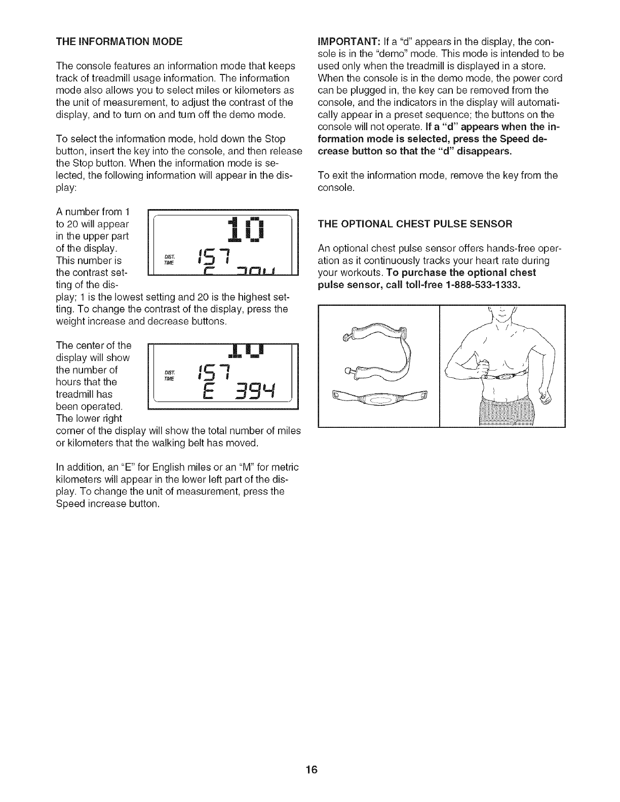
A number from 1
to 20 will appear
in the upper part
of the display.
This number is
the contrast set-
ting of the dis-
4 |"_
|||
m mm
0,st;5-1
TIME
play; 1 is the lowest setting and 20 is the highest set-
ting. To change the contrast of the display, press the
weight increase and decrease buttons.
The center of the
display will show
the number of
hours that the
treadmill has
been operated.
The lower right
r-i-|
minim m
= 151
TIME E 39q
corner of the display will show the total number of miles
or kilometers that the walking belt has moved.
In addition, an "E" for English miles or an "M" for metric
kilometers will appear in the lower left part of the dis-
play. To change the unit of measurement, press the
Speed increase button.
IMPORTANT: If a "d" appears in the display, the con-
sole is in the "demo" mode. This mode is intended to be
used only when the treadmill is displayed in a store.
When the console is in the demo mode, the power cord
can be plugged in, the key can be removed from the
console, and the indicators in the display will automati-
cally appear in a preset sequence; the buttons on the
console will not operate. If a "d" appears when the in-
formation mode is selected, press the Speed de-
crease button so that the "d" disappears.
To exit the information mode, remove the key from the
console.
THE OPTIONAL CHESTPULSESENSOR
An optional chest pulse sensor offers hands-free oper-
ation as it continuously tracks your heart rate during
your workouts. To purchase the optional chest
pulse sensor, call toll-free 1-888-533-1333.
16
HOW TO FOLD AND MOVE THE TREADMILL
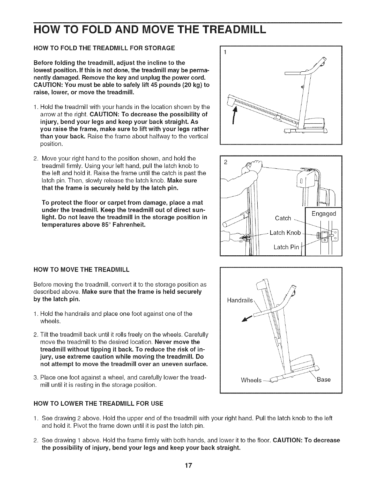
NOW TO FOLD THE TREADMILL FOR STORAGE
Before folding the treadmill, adjust the incline to the
lowest position. If this is not done, the treadmill may be perma=
nently damaged. Remove the key and unplug the power cord.
CAUTION: You must be able to safely lift 45 pounds (20 kg) to
raise, lower, or move the treadmill.
1. Hold the treadmill with your hands in the location shown by the
arrow at the right. CAUTION: To decrease the possibility of
injury, bend your legs and keep your back straight. As
you raise the frame, make sure to lift with your legs rather
than your back. Raise the frame about halfway to the vertical
position.
2. Move your right hand to the position shown, and hold the
treadmill firmly. Using your left hand, pull the latch knob to
the left and hold it. Raise the frame until the catch is past the
latch pin. Then, slowly release the latch knob. Make sure
that the frame is securely held by the latch pin.
To protect the floor or carpet from damage, place a mat
under the treadmill. Keep the treadmill out of direct sun=
light. Do not leave the treadmill in the storage position in
temperatures above 85 ° Fahrenheit.
Engaged
Catch
Latch Knob ._
Latch Pin b _
!
HOW TO MOVE THE TREADMILL
Before moving the treadmill, convert it to the storage position as
described above. Make sure that the frame is held securely
by the latch pin.
1. Hold the handrails and place one foot against one of the
wheels.
2. Tilt the treadmill back until it rolls freely on the wheels. Carefully
move the treadmill to the desired location. Never move the
treadmill without tipping it back. To reduce the risk of in-
jury, use extreme caution while moving the treadmill. Do
not attempt to move the treadmill over an uneven surface.
3. Place one foot against a wheel, and carefully lower the tread-
mill until it is resting in the storage position. Wheels
HOW TO LOWER THE TREADMILL FOR USE
1. See drawing 2 above. Hold the upper end of the treadmill with your right hand. Pull the latch knob to the left
and hold it. Pivot the frame down until it is past the latch pin.
2. See drawing 1 above. Hold the frame firmly with both hands, and lower it to the floor. CAUTION: To decrease
the possibility of injury, bend your legs and keep your back straight.
17
TROUBLESHOOTING
Most treadmill problems can be solved by following the simple steps below. Find the symptom that
applies, and follow the steps listed. If further assistance is needed, call toIFfree 1=800=4-MY=HOME®
(1=800=469=4663).
PROBLEM: The power does not turn on
SOLUTION: a. Make sure that the power cord is plugged into a surge suppressor, and that the surge suppressor
is plugged into a properly grounded outlet (see page 9). Use only a single-outlet surge suppressor
that meets all of the specifications described on page 9. Important: The treadmill is not compatible
with GFCl-equipped outlets.
b. After the power cord has been plugged in, make sure that the key is inserted into the console.
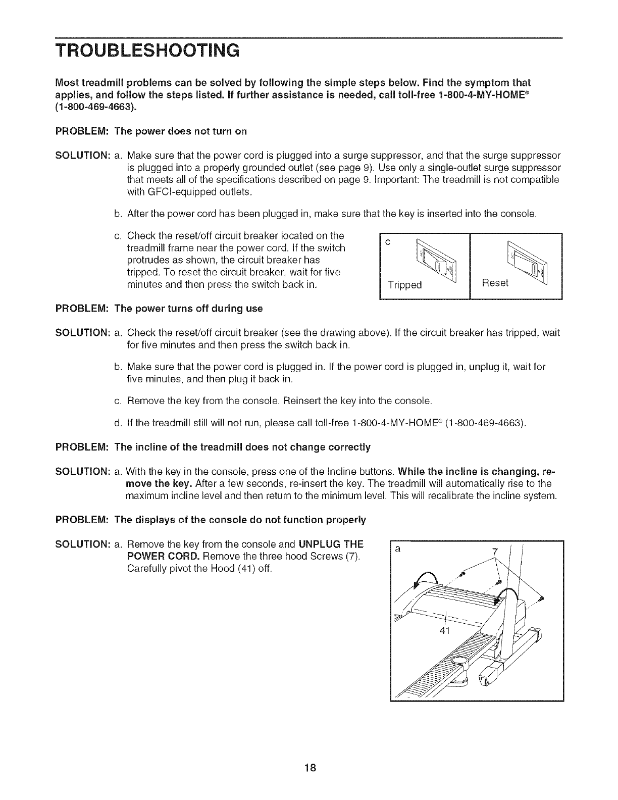
Check the reset/off circuit breaker located on the
treadmill frame near the power cord. If the switch
protrudes as shown, the circuit breaker has
tripped. To reset the circuit breaker, wait for five
minutes and then press the switch back in. Tripped Reset
PROBLEM: The power turns off during use
SOLUTION: a. Check the reset/off circuit breaker (see the drawing above). If the circuit breaker has tripped, wait
for five minutes and then press the switch back in.
b. Make sure that the power cord is plugged in. If the power cord is plugged in, unplug it, wait for
five minutes, and then plug it back in.
c. Remove the key from the console. Reinsert the key into the console.
d. If the treadmill still will not run, please call toll-free 1-800-4-MY-HOME ®(1-800-469-4663).
PROBLEM: The incline of the treadmill does not change correctly
SOLUTION: a. With the key in the console, press one of the Incline buttons. While the incline is changing, re-
move the key. After a few seconds, re-insert the key. The treadmill will automatically rise to the
maximum incline level and then return to the minimum level. This will recalibrate the incline system.
PROBLEM: The displays of the console do not function properly
SOLUTION: a. Remove the key from the console and UNPLUG THE
POWER CORD. Remove the three hood Screws (7).
Carefully pivot the Hood (41) off.
41
18
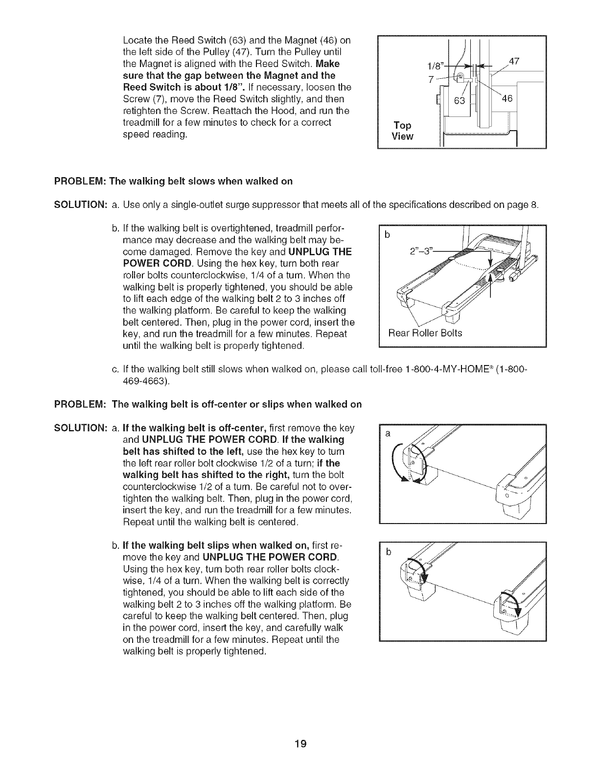
Locate the Reed Switch (63) and the Magnet (46) on
the left side of the Pulley (47). Turn the Pulley until
the Magnet is aligned with the Reed Switch. Make
sure that the gap between the Magnet and the
Reed Switch is about 1/8". if necessary, loosen the
Screw (7), move the Reed Switch slightly, and then
retighten the Screw. Reattach the Hood, and run the
treadmill for a few minutes to check for a correct
speed reading. Top
View
1/8"-
7
47
PROBLEM: The walking belt slows when walked on
SOLUTION: a. Use only a single-outlet surge suppressor that meets all of the specifications described on page 8.
b. If the walking belt is overtightened, treadmill perfor-
mance may decrease and the walking belt may be-
come damaged. Remove the key and UNPLUG THE
POWER CORD. Using the hex key, turn both rear
roller bolts counterclockwise, 1/4 of a turn. When the
walking belt is properly tightened, you should be able
to lift each edge of the walking belt 2 to 3 inches off
the walking platform. Be careful to keep the walking
belt centered. Then, plug in the power cord, insert the
key, and run the treadmill for a few minutes. Repeat
until the walking belt is properly tightened.
Rear Roller Bolts
c. If the walking belt still slows when walked on, please call toll-free 1-800-4-MY-HOME _ (1-800-
469-4663).
PROBLEM: The walking belt is off-center or slips when walked on
SOLUTION: a. if the walking belt is off-center, first remove the key
and UNPLUG THE POWER CORD. if the walking
belt has shifted to the left, use the hex key to turn
the left rear roller bolt clockwise 1/2 of a turn; if the
walking belt has shifted to the right, turn the bolt
counterclockwise 1/2 of a turn. Be careful not to over-
tighten the walking belt. Then, plug in the power cord,
insert the key, and run the treadmill for a few minutes.
Repeat until the walking belt is centered.
b. if the walking belt slips when walked on, first re-
move the key and UNPLUG THE POWER CORD.
Using the hex key, turn both rear roller bolts clock-
wise, 1/4 of a turn. When the walking belt is correctly
tightened, you should be able to lift each side of the
walking belt 2 to 3 inches off the walking platform. Be
careful to keep the walking belt centered. Then, plug
in the power cord, insert the key, and carefully walk
on the treadmill for a few minutes. Repeat until the
walking belt is properly tightened.
19
CONDiTiONiNG GUiDELiNES
begin to use stored fatcaloriesfor energy. If your goal
is to burn fat, adjust the speed and incline of the tread-
mill until your heart rate is near the lowest number in
your training zone.
For maximum fat burning, adjust the speed and incline
of the treadmill until your heart rate is near the middle
number in your training zone.
Aerobic Exercise
If your goal is to strengthen your cardiovascular sys-
tem, your exercise must be "aerobic." Aerobic exercise
is activity that requires large amounts of oxygen for
The following guidelines will help you to plan your ex-
ercise program. For more detailed exercise informa-
tion, obtain a reputable book or consult your physician.
EXERCISE iNTENSiTY
prolonged periods of time. This increases the demand
on the heart to pump blood to the muscles, and on the
lungs to oxygenate the blood. For aerobic exercise,
adjust the speed and incline of the treadmill until your
heart rate is near the highest number in your training
zone.
Whether your goal is to burn fat or to strengthen your
cardiovascular system, the key to achieving the
desired results is to exercise with the proper intensity.
The proper intensity level can be found by using your
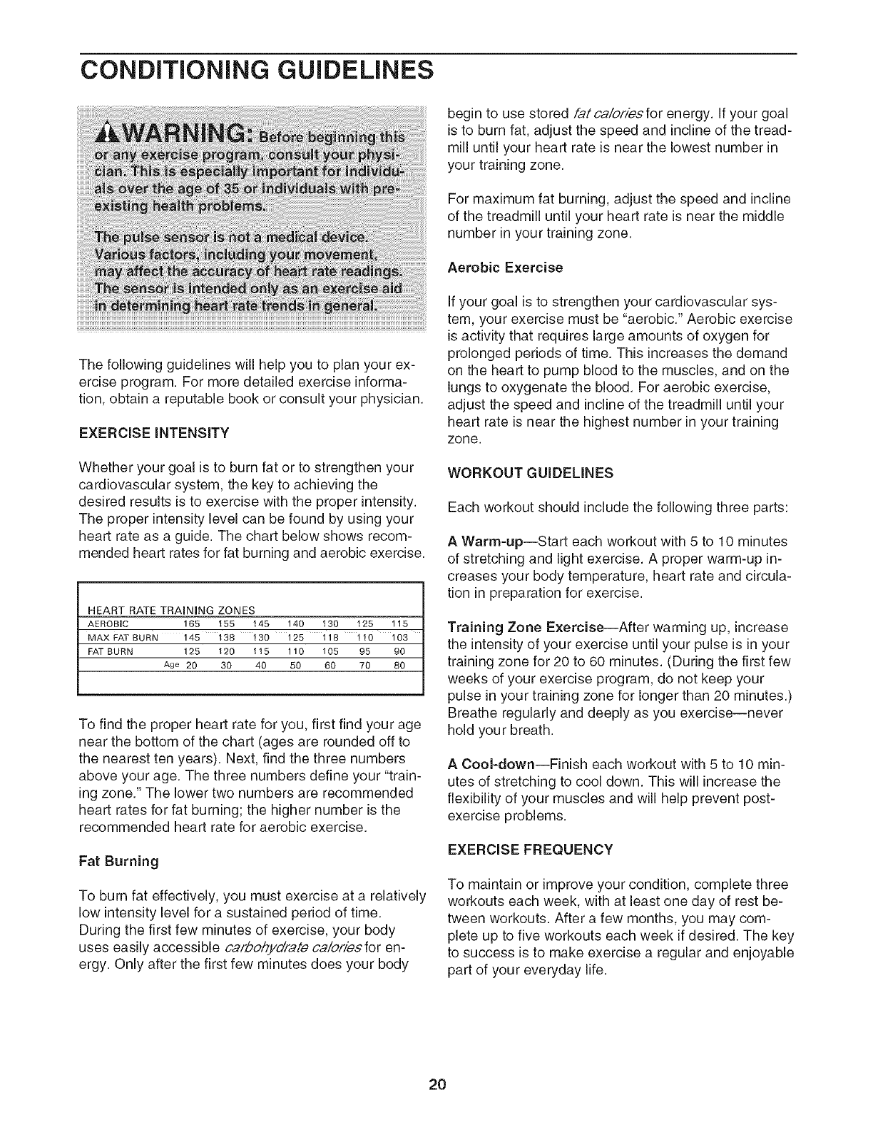
heart rate as a guide. The chart below shows recom-
mended heart rates for fat burning and aerobic exercise.
HEART RATE TRAINING ZONES
AEROBIC 165 155 145 140 130 125 115
MAX FAT BURN 145 138 130 125 118 110 103
FAT BURN 125 120 115 110 105 95 90
Age 20 30 40 50 60 70 80
To find the proper heart rate for you, first find your age
near the bottom of the chart (ages are rounded off to
the nearest ten years). Next, find the three numbers
above your age. The three numbers define your "train-
ing zone." The lower two numbers are recommended
heart rates for fat burning; the higher number is the
recommended heart rate for aerobic exercise.
Fat Burning
To burn fat effectively, you must exercise at a relatively
low intensity level for a sustained period of time.
During the first few minutes of exercise, your body
uses easily accessible cafbohydfa,_e ca/ofiesfor en-
ergy. Only after the first few minutes does your body
WORKOUT GUIDELINES
Each workout should include the following three parts:
A Warm=up--Start each workout with 5 to 10 minutes
of stretching and light exercise. A proper warm-up in-
creases your body temperature, heart rate and circula-
tion in preparation for exercise.
Training Zone Exercise--After warming up, increase
the intensity of your exercise until your pulse is in your
training zone for 20 to 60 minutes. (During the first few
weeks of your exercise program, do not keep your
pulse in your training zone for longer than 20 minutes.)
Breathe regularly and deeply as you exercise--never
hold your breath.
ACool=down--Finish each workout with 5 to 10 min-
utes of stretching to cool down. This will increase the
flexibility of your muscles and will help prevent post-
exercise problems.
EXERCISE FREQUENCY
To maintain or improve your condition, complete three
workouts each week, with at least one day of rest be-
tween workouts. After a few months, you may com-
plete up to five workouts each week if desired. The key
to success is to make exercise a regular and enjoyable
part of your everyday life.
20
SUGGESTED STRETCHES
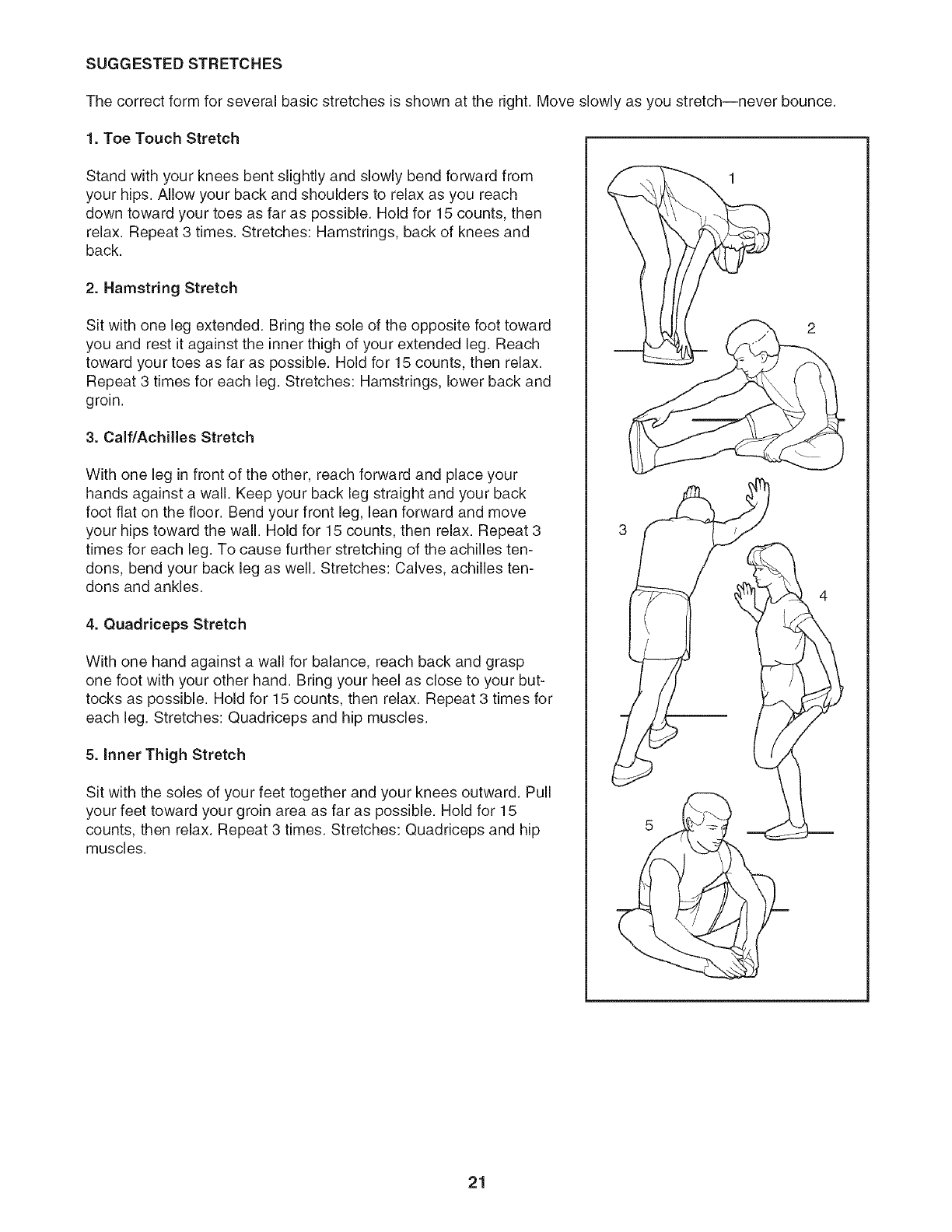
The correct form for several basic stretches is shown at the right. Move slowly as you stretch--never bounce.
1. Toe Touch Stretch
Stand with your knees bent slightly and slowly bend forward from
your hips. Allow your back and shoulders to relax as you reach
down toward your toes as far as possible. Hold for 15 counts, then
relax. Repeat 3 times. Stretches: Hamstrings, back of knees and
back.
2. Hamstring Stretch
Sit with one leg extended. Bring the sole of the opposite foot toward
you and rest it against the inner thigh of your extended leg. Reach
toward your toes as far as possible. Hold for 15 counts, then relax.
Repeat 3 times for each leg. Stretches: Hamstrings, lower back and
groin.
3. Calf/Achilles Stretch
With one leg in front of the other, reach forward and place your
hands against a wall. Keep your back leg straight and your back
foot flat on the floor. Bend your front leg, lean forward and move
your hips toward the wall. Hold for 15 counts, then relax. Repeat 3
times for each leg. To cause further stretching of the achilles ten-
dons, bend your back leg as well. Stretches: Calves, achilles ten-
dons and ankles.
4. Quadriceps Stretch
With one hand against a wall for balance, reach back and grasp
one foot with your other hand. Bring your heel as close to your but-
tocks as possible. Hold for 15 counts, then relax. Repeat 3 times for
each leg. Stretches: Quadriceps and hip muscles.
5. Inner Thigh Stretch
Sit with the soles of your feet together and your knees outward. Pull
your feet toward your groin area as far as possible. Hold for 15
counts, then relax. Repeat 3 times. Stretches: Quadriceps and hip
muscles.
21
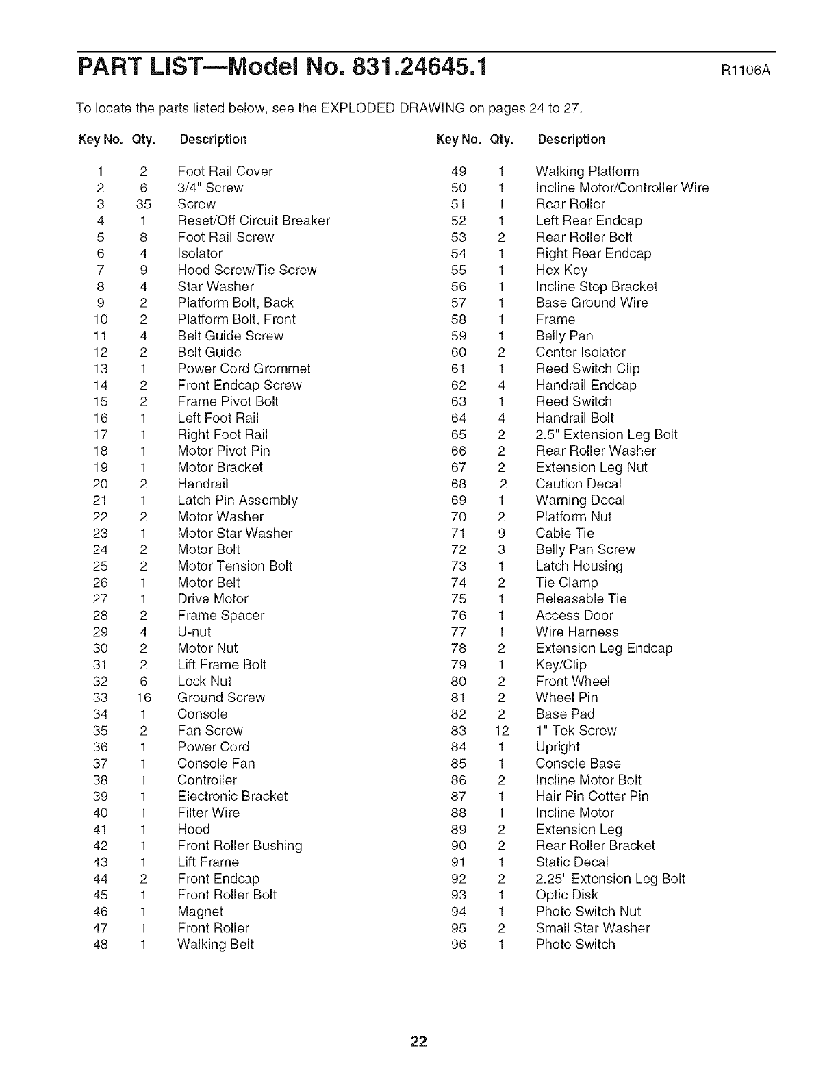
PART LiST--Model No. 831.24645.1 RttO6A
To locate the parts listed below, see the EXPLODED DRAWING on pages 24 to 27.
Key No. Qty. Description Key No. Qty. Description
1 2 Foot Rail Cover 49 1 Walking Platform
2 6 3/4" Screw 50 1 Incline Motor/Controller Wire
3 35 Screw 51 1 Rear Roller
4 1 Reset/Off Circuit Breaker 52 1 Left Rear Endcap
5 8 Foot Rail Screw 53 2 Rear Roller Bolt
6 4 Isolator 54 1 Right Rear Endcap
7 9 Hood Screw/Tie Screw 55 1 Hex Key
8 4 Star Washer 56 1 Incline Stop Bracket
9 2 Platform Bolt, Back 57 1 Base Ground Wire
10 2 Platform Bolt, Front 58 1 Frame
11 4 Belt Guide Screw 59 1 Belly Pan
12 2 Belt Guide 60 2 Center Isolator
13 1 Power Cord Grommet 61 1 Reed Switch Clip
14 2 Front Endcap Screw 62 4 Handrail Endcap
15 2 Frame Pivot Bolt 63 1 Reed Switch
16 1 Left Foot Rail 64 4 Handrail Bolt
17 1 Right Foot Rail 65 2 2.5" Extension Leg Bolt
18 1 Motor Pivot Pin 66 2 Rear Roller Washer
19 1 Motor Bracket 67 2 Extension Leg Nut
20 2 Handrail 68 2 Caution Decal
21 1 Latch Pin Assembly 69 1 Warning Decal
22 2 Motor Washer 70 2 Platform Nut
23 1 Motor Star Washer 71 9 Cable Tie
24 2 Motor Bolt 72 3 Belly Pan Screw
25 2 Motor Tension Bolt 73 1 Latch Housing
26 1 Motor Belt 74 2 Tie Clamp
27 1 Drive Motor 75 1 Releasable Tie
28 2 Frame Spacer 76 1 Access Door
29 4 U-nut 77 1 Wire Harness
30 2 Motor Nut 78 2 Extension Leg Endcap
31 2 Lift Frame Bolt 79 1 Key/Clip
32 6 Lock Nut 80 2 Front Wheel
33 16 Ground Screw 81 2 Wheel Pin
34 1 Console 82 2 Base Pad
35 2 Fan Screw 83 12 1" Tek Screw
36 1 Power Cord 84 1 Upright
37 1 Console Fan 85 1 Console Base
38 1 Controller 86 2 Incline Motor Bolt
39 1 Electronic Bracket 87 1 Hair Pin Cotter Pin
40 1 Filter Wire 88 1 Incline Motor
41 1 Hood 89 2 Extension Leg
42 1 Front Roller Bushing 90 2 Rear Roller Bracket
43 1 Lift Frame 91 1 Static Decal
44 2 Front Endcap 92 2 2.25" Extension Leg Bolt
45 1 Front Roller Bolt 93 1 Optic Disk
46 1 Magnet 94 1 Photo Switch Nut
47 1 Front Roller 95 2 Small Star Washer
48 1 Walking Belt 96 1 Photo Switch
22
Key No. Qty.
97 1
98 2
99 1
100 3
101 1
102 1
103 2
104 2
105 2
106 4
107 4
108 4
109 1
110 1
111 1
Description
Photo Switch Bolt
Dumbbell
Latch Plate
Wire Tie
Roller Ground Wire
Photo Switch Wire
Isolator Bracket Cover
Center Isolator Bolt
Rear Roller Lock Washer
Crossbar Screw
Crossbar Star Washer
Console Screw
Crossbar
Fan Cover
Console Ground Wire
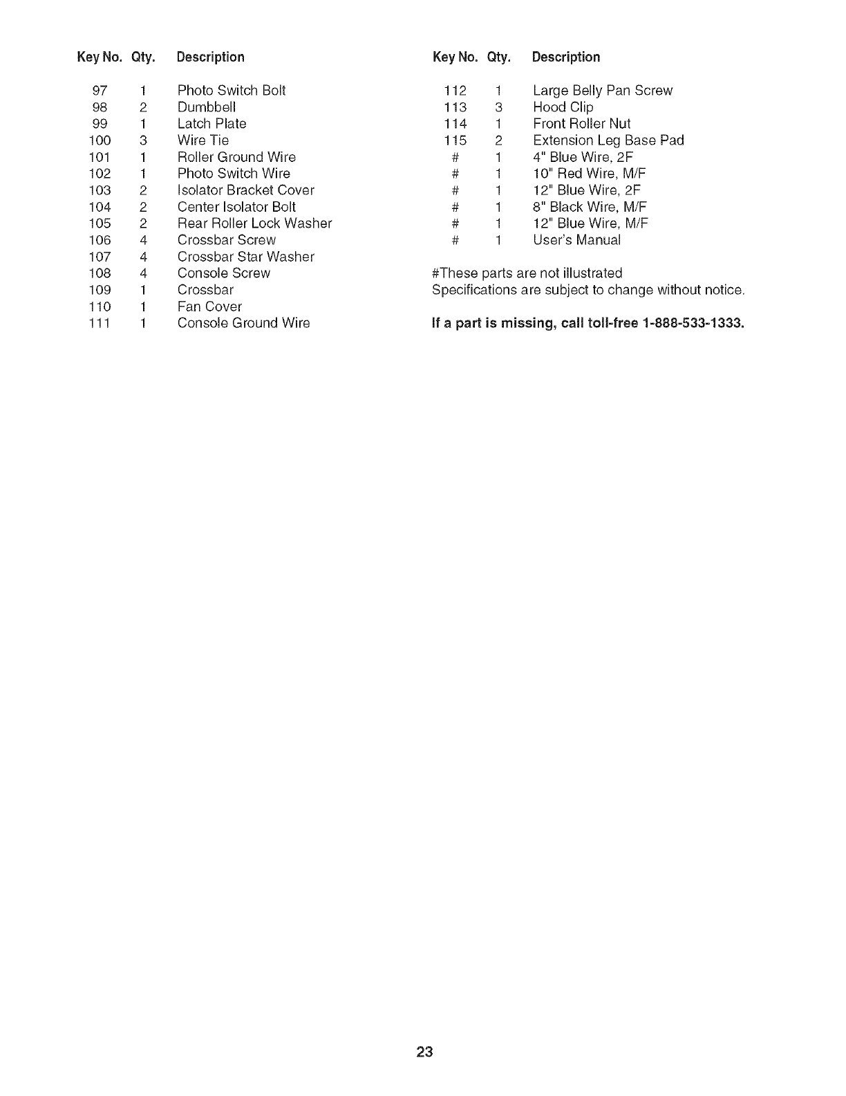
Key No. Qty. Description
112 1 Large Belly Pan Screw
113 3 Hood Clip
114 1 Front Roller Nut
115 2 Extension Leg Base Pad
# 1 4" Blue Wire, 2F
# 1 10" Red Wire, M/F
# 1 12" Blue Wire, 2F
# 1 8" Black Wire, M/F
# 1 12" Blue Wire, M/F
# 1 User's Manual
#These parts are not illustrated
Specifications are subject to change without notice.
if apart is missing, call toll-free 1-888-533-1333.
23
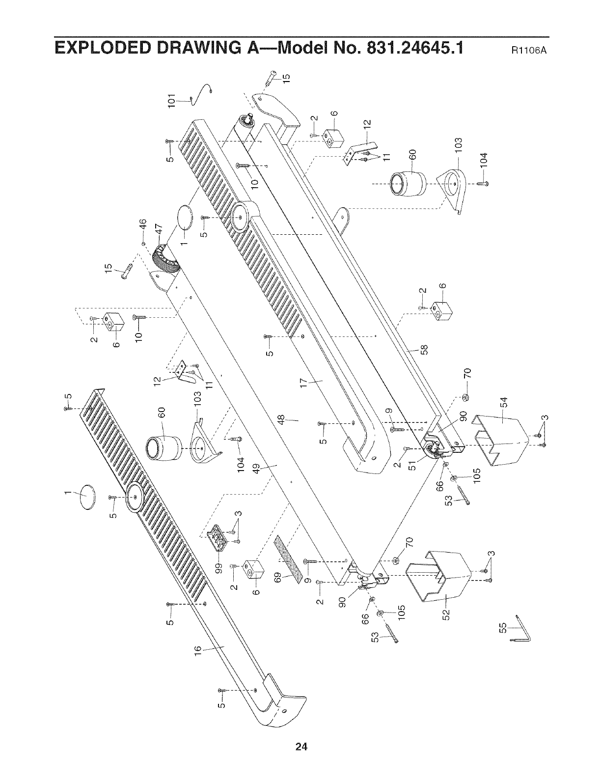
EXPLODED DRAWING A--Model No. 831.24645.1 ml06A
LO
co
"r--
04 _O "r-- /
,LO
03
LO O
_-- O "r-
CO
f..
"r-
__
LO
O4
CO
cO
o
f-.
LO
LO
my
00_
/ /
co
S
GO
O4
0
LO
T-
O4
LO
CO
LO
LO
24
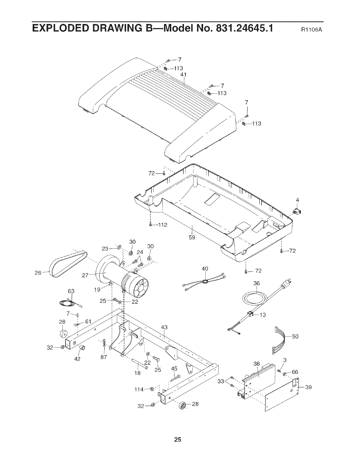
EXPLODED DRAWING B--Model No. 831.24645.1 mlo6A
30
63 1
i ii
25_22,
42 87
43
18 45
59
40
i
i
72
36
38
_3<
4
i
i
&--72
3
3
25
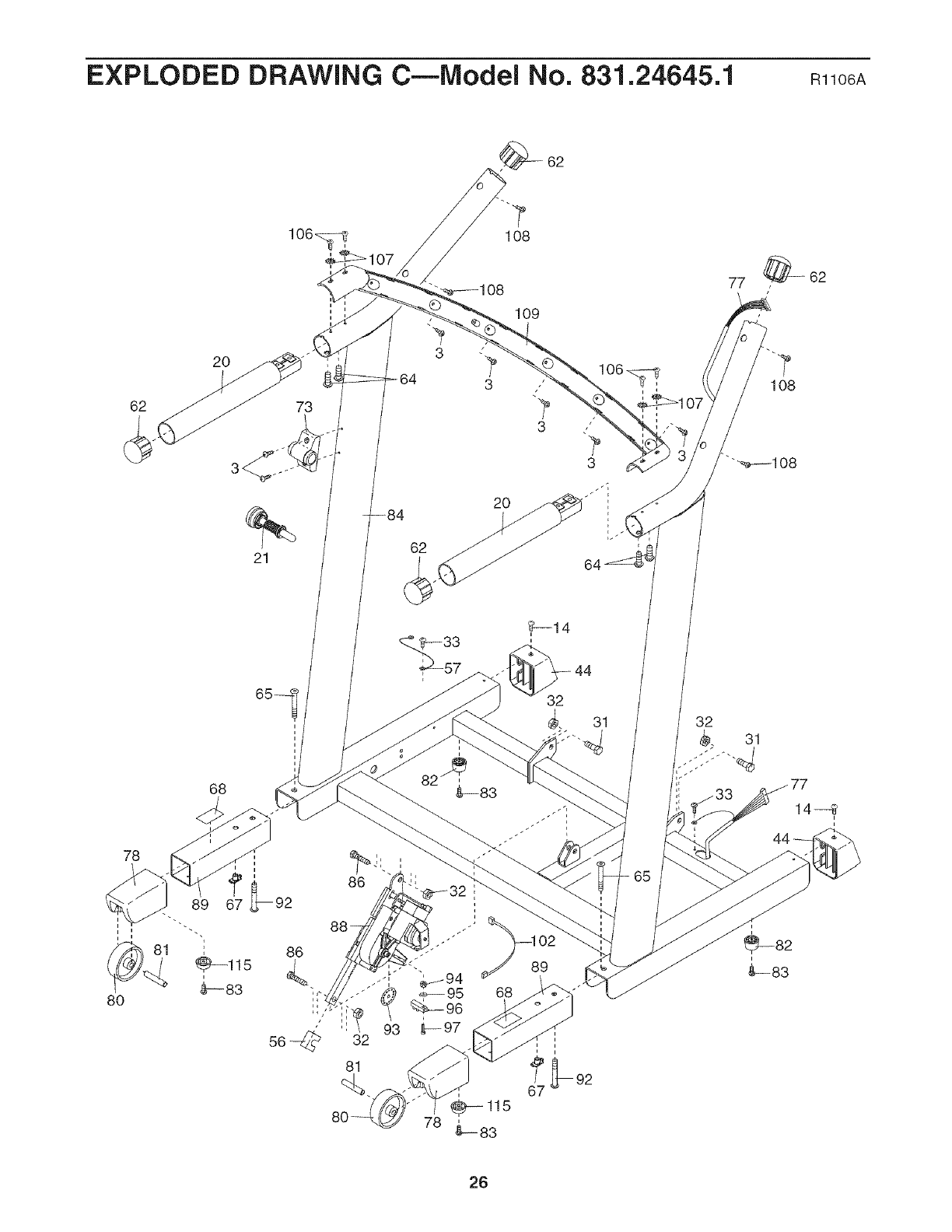
EXPLODED DRAWING C--Model No. 831.24645.1 Rllo6A
7
108
109
68
56-@
86
32
89
77 _ 62
1O8
44
26
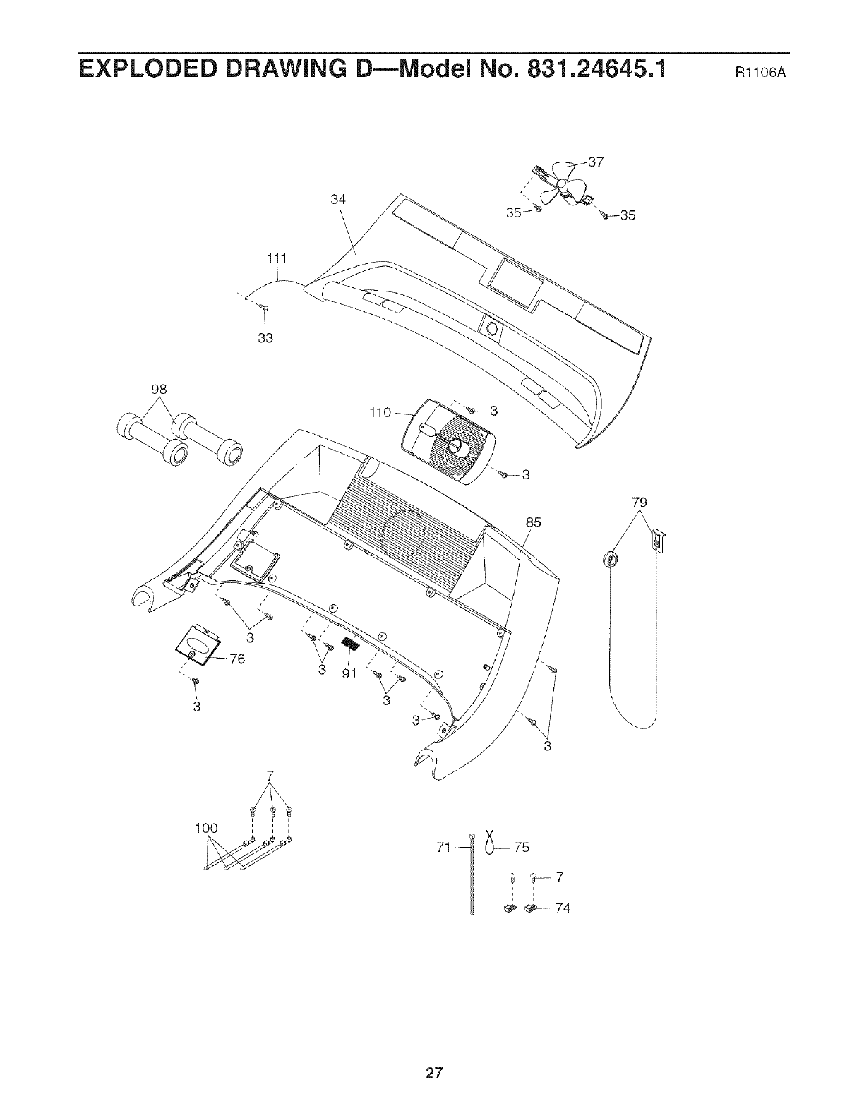
EXPLODED DRAWING D--Model No. 831.24645.1 mlo6A
34
37
111
33
98
3
3
100 = = =
= = =
_--75
_ %-7
_- 74
27

iiiiiiiiiiiiiiii'
iiiiiiiiiiiiiiii
iiiiiiiiiiiiiiii
iiiiiiiiiiiiiiii
iiiiiiiiiiiiiiii
iiiiiiiiiiiiiiii
iiiiiiiiiiiiiiii
iiiiiiiiiiiiiiii
iiiiiiiiiiiiiiii
iiiiiiiiiiiiiiii
iiiiiiiiiiiiiiii
iiiiiiiiiiiiiiii
iiiiiiiiiiiiiiii
iiiiiiiiiiiiiiii
iiiiiiiiiiiiiiii
iiiiiiiiiiiiiiii
iiiiiiiiiiiiiiii
iiiiiiiiiiiiiiii
iiiiiiiiiiiiiiii
iiiiiiiiiiiiiiii
iiiiiiiiiiiiiiii
iiiiiiiiiiiiiiii
iiiiiiiiiiiiiiii
iiiiiiiiiiiiiiii
iiiiiiiiiiiiiiii
iiiiiiiiiiiiiiii
iiiiiiiiiiiiiiii
iiiiiiiiiiiiiiii
iiiiiiiiiiiiiiii
iiiiiiiiiiiiiiii
uuuuuuu_
Your Home
For repair--in your home--of all major brand appliances, lawn and garden equipment,
or heating and cooling systems, no matter who made it, no matter who sold it!
For the replacement parts, accessories, and user's manuals that you need to do-it-yourself.
For Sears professional installation of home appliances
and items like garage door openers and water heaters.
1-800-4-MY-HOM E®(1-800-469-4663)
Call anytime, day or night (U.S.A. and Canada)
www.sears.oom www.eears.ca
Our Home
For repair of carry-in items like vacuums, lawn equipment,
and electronics, call or go on-line for the location of your nearest
Sears Parts & Repair Center.
1-800-488-1222 Call anytime, day or night (U.S.A. only)
www.sears.oom
To purchase a protection agreement (U.S.A.)
or maintenance agreement (Canada) on a product serviced by Sears:
1-800-827-6655 (U.S.A.) 1-800-361-6665 (Canada)
® Registered Trademark /TMTrademark /SMService Mark of Sears Brands, LLC
@ Marca Registrada /TMMarca de Fabrica /SMMarca de Servicio de Sears Brands, LLC
f
90 DAY FULL WARRANTY
if this Sears Treadmill Exerciser fails due to a defect in material or workmanship within 90 days of the
date of purchase, call 1-800-4-MY-HOME _ (1-800-469-4663) to arrange for free repair (or replacement if
repair proves impossible). The drive motor is warranted for 12 years from the date of purchase.
This warranty does not apply when the Treadmill Exerciser is used commercially or for rental purposes.
This warranty gives you specific legal rights, and you may also have other rights which vary from state to
state.
Sears, Roebuck and Co., Hoffman Estates, IL 60179
J
.J
Part No. 250130 R1106A Printed in USA @ 2006 ICON IP, inc.
