Proform 831248650 User Manual XP CROSSWALK 580 Manuals And Guides L0808126
PROFORM Treadmill Manual L0808126 PROFORM Treadmill Owner's Manual, PROFORM Treadmill installation guides
User Manual: Proform 831248650 831248650 PROFORM PROFORM XP CROSSWALK 580 - Manuals and Guides View the owners manual for your PROFORM PROFORM XP CROSSWALK 580 #831248650. Home:Fitness Equipment Parts:Proform Parts:Proform PROFORM XP CROSSWALK 580 Manual
Open the PDF directly: View PDF ![]() .
.
Page Count: 32
Model No. 831.24865.0
Serial No.
Write the serial number in the space
above for reference.
Serial Number _
Decal
. Assembly
.Operation
" Maintenance
o Part List and Drawing
TREADMI LL EXERCISER
User's Manual
Sears, Roebuck and Co., Hoffman Estates, IL 80179
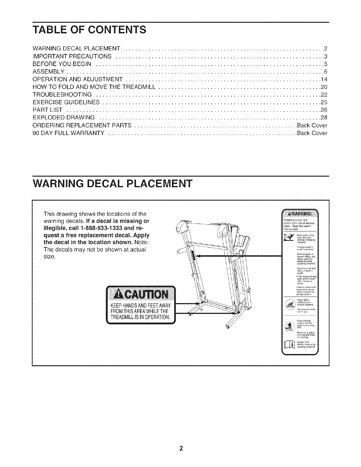
TABLE OF CONTENTS
WARNING DECAL PLACEMENT .............................................................. 2
IMPORTANT PRECAUTIONS ................................................................ 3
BEFORE YOU BEGIN ...................................................................... 5
ASSEMBLY ............................................................................... 6
OPERATION AND ADJUSTMENT ............................................................ 14
HOW TO FOLD AND MOVE THE TREADMILL .................................................. 20
TROUBLESHOOTING ..................................................................... 22
EXERCISE GUIDELINES ................................................................... 25
PART LIST .............................................................................. 26
EXPLODED DRAWING .................................................................... 28
ORDERING REPLACEMENT PARTS .................................................. Back Cover
90 DAY FULL WARRANTY .......................................................... Back Cover
WARNING DECAL PLACEMENT
This drawing shows the locations of the
warning decals. If a decal is missing or
illegible, call 1-888-533-1333 and re-
quest a free replacement decal. Apply
the decal in the location shown. Note:
The decals may not be shown at actual
size.
KEEPHANDSANDFEETAWAY
FROMTHISAREAWHILETHE
TREADMILLISINOPERATION,
2

iMPORTANT PRECAUTIONS
3
4
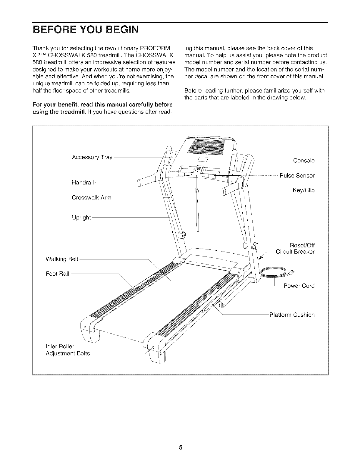
BEFORE YOU BEGIN
Thank you for selecting the revolutionary PROFORM
XP TM CROSSWALK 580 treadmill. The CROSSWALK
580 treadmill offers an impressive selection of features
designed to make your workouts at home more enjoy-
able and effective. And when you're not exercising, the
unique treadmill can be folded up, requiring less than
half the floor space of other treadmills.
For your benefit, read this manual carefully before
using the treadmill If you have questions after read-
ing this manual, please see the back cover of this
manual. To help us assist you, please note the product
model number and serial number before contacting us.
The model number and the location of the serial num-
ber decal are shown on the front cover of this manual.
Before reading further, please familiarize yourself with
the parts that are labeled in the drawing below.
Accessory Tray
Handrail
Crosswalk Arm
Console
Pulse Sensor
Key/Clip
Upright
Walking Belt \
Foot Rail
Reset/Off
_Circuit Breaker
Power Cord
Platform Cushion
Idler Roller
Adjustment Bolts
5
ASSEMBLY
Assembly requires two persons. Set the treadmill in a cleared area and remove all packing materials. Do not
dispose of the packing materials until assembly is completed. Note: The underside of the treadmill walking belt is
coated with high-performance lubricant. During shipping, a small amount of lubricant may be transferred to the
top of the walking belt or the shipping carton. This is a normal condition and does not affect treadmill perfor-
mance. If there is lubricant on top of the walking belt, simply wipe off the lubricant with a soft cloth and a mild,
non-abrasive cleaner.
Assembly requires the included h_ and your own Phillips screwdriver _ ,
adjustable wrench _, needlenose pliers _,=_, scissors _ , and rubber mallet.
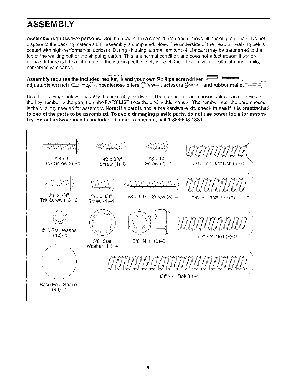
Use the drawings below to identify the assembly hardware. The number in parentheses below each drawing is
the key number of the part, from the PART LIST near the end of this manual. The number after the parentheses
is the quantity needed for assembly. Note: If a part is not in the hardware kit, check to see if it is preattached
to one of the parts to be assembled. To avoid damaging plastic parts, do not use power tools for assem-
bly. Extra hardware may be included, if a part is missing, call 1-888-533-1333.
# 8 x 1" #8 x 3/4" #8 x 1/2"
Tek Screw (6)-4 Screw (1)-8 Screw (2)-2 5/16" x 1 3/4" Bolt (5)-4
# 8 x 3/4" #10 x 3/4"
Tek Screw (13)-2 Screw (4)-4 #8 x 1 1/2" Screw (3)-4 3/8" x 1 3/4" Bolt (7)-1
#10 Star Washer
(12)-4
x\
3/8" Star
Washer (11)-4 3/8" Nut (10)-3 3/8" x 2" Bolt (9)-3
Base Foot Spacer
(98)-2
3/8" x 4" Bolt (8)-4
6
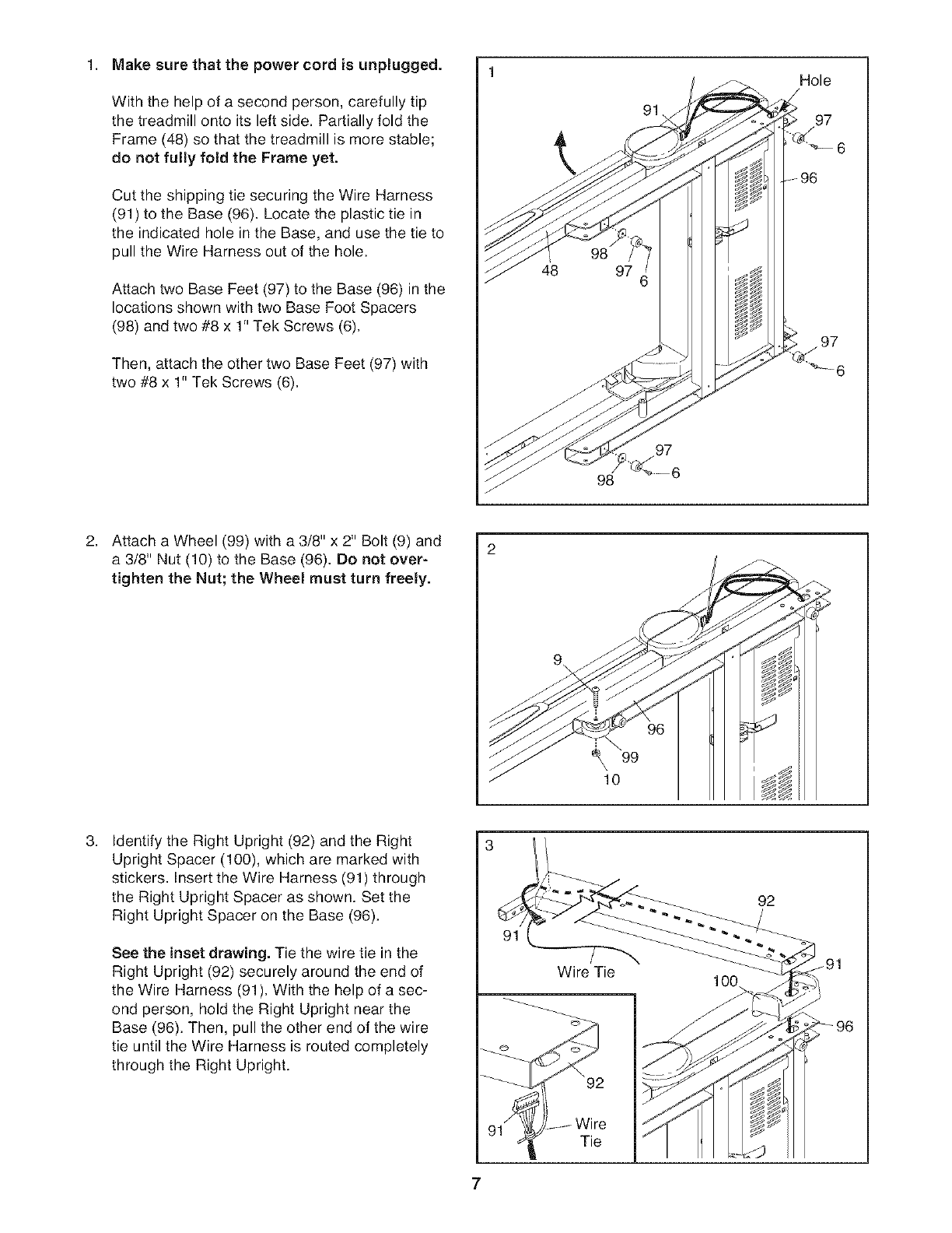
1. Make sure that the power cord is unplugged.
With the help of a second person, carefully tip
the treadmill onto its left side. Partially fold the
Frame (48) so that the treadmill is more stable;
do not fully fold the Frame yet.
Cut the shipping tie securing the Wire Harness
(91) to the Base (96). Locate the plastic tie in
the indicated hole in the Base, and use the tie to
pull the Wire Harness out of the hole.
Attach two Base Feet (97) to the Base (96) in the
locations shown with two Base Foot Spacers
(98) and two #8 x 1" Tek Screws (6).
Then, attach the other two Base Feet (97) with
two #8 x 1" Tek Screws (6).
98
Hole
/
97
2. Attach a Wheel (99) with a 3/8" x 2" Bolt (9) and
a 3/8" Nut (10) to the Base (96). Do not over-
tighten the Nut; the Wheel must turn freely.
2
¢ 99
\10
3. Identify the Right Upright (92) and the Right
Upright Spacer (100), which are marked with
stickers. Insert the Wire Harness (91) through
the Right Upright Spacer as shown. Set the
Right Upright Spacer on the Base (96).
See the inset drawing. Tie the wire tie in the
Right Upright (92) securely around the end of
the Wire Harness (91). With the help of a sec-
ond person, hold the Right Upright near the
Base (96). Then, pull the other end of the wire
tie until the Wire Harness is routed completely
through the Right Upright.
Wire Tie
Tie
92
100
7
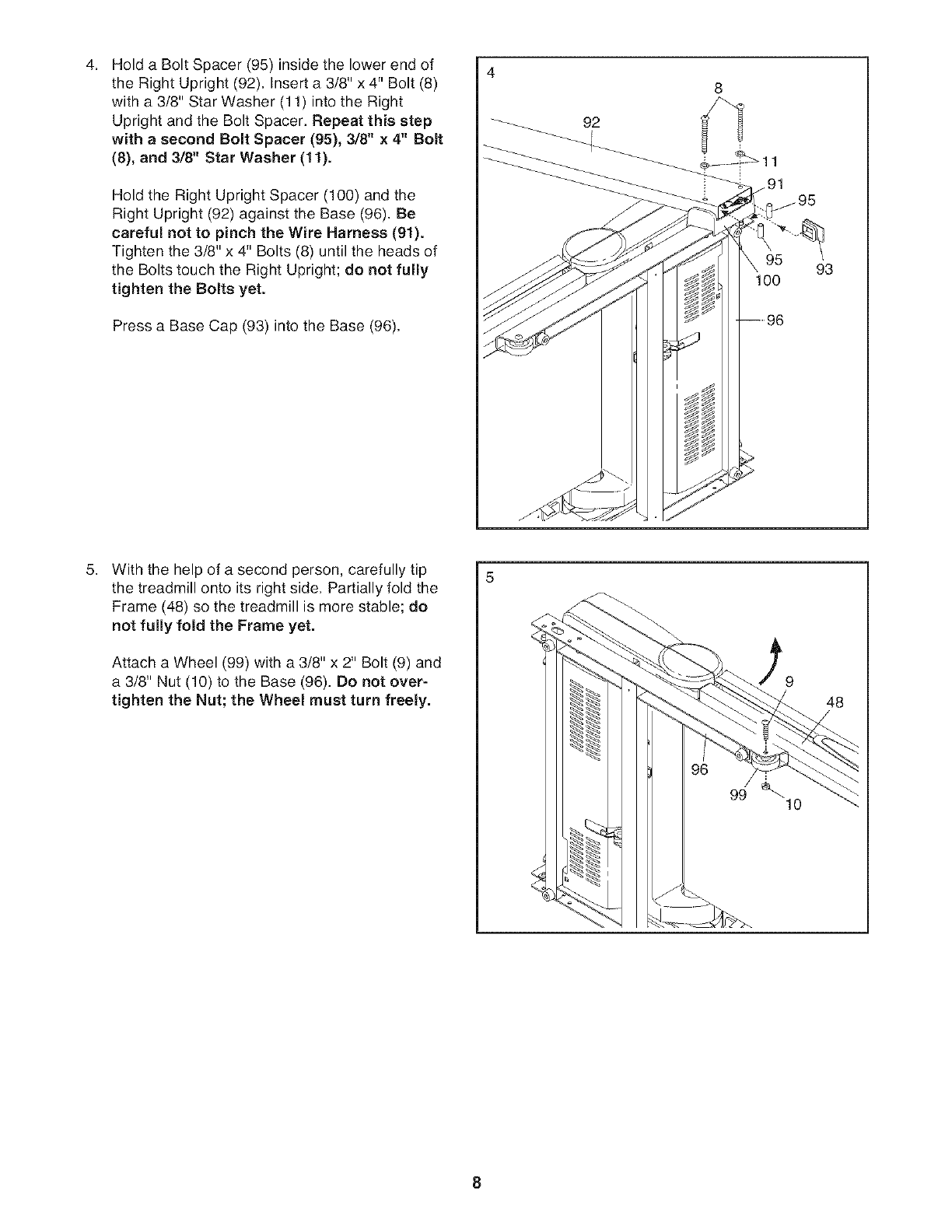
4, Hold a Bolt Spacer (95) inside the lower end of
the Right Upright (92), Insert a 3/8" x 4" Bolt (8)
with a 3/8" Star Washer (11) into the Right
Upright and the Bolt Spacer, Repeat this step
with a second Bolt Spacer (95), 3/8" x 4" Bolt
(8), and 3/8" Star Washer (11).
Hold the Right Upright Spacer (100) and the
Right Upright (92) against the Base (96). Be
careful not to pinch the Wire Harness (91).
Tighten the 3/8" x 4" Bolts (8) until the heads of
the Bolts touch the Right Upright; do not fully
tighten the Bolts yet.
Press a Base Cap (93) into the Base (96).
4
92
8
100 93
5, With the help of a second person, carefully tip
the treadmill onto its right side. Partially fold the
Frame (48) so the treadmill is more stable; do
not fully fold the Frame yet.
Attach a Wheel (99) with a 3/8" x 2" Bolt (9) and
a 3/8" Nut (10) to the Base (96). Do not over-
tighten the Nut; the Wheel must turn freely. 48
10
8
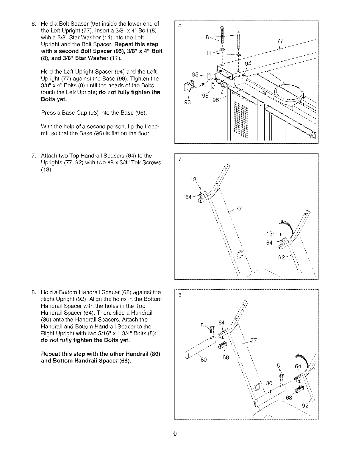
6. Hold a Bolt Spacer (95) inside the lower end of
the Left Upright (77). Insert a 3/8" x 4" Bolt (8)
with a 3/8" Star Washer (11) into the Left
Upright and the Bolt Spacer. Repeat this step
with a second Bolt Spacer (95), 3/8" x 4" Bolt
(8), and 3/8" Star Washer (11).
Hold the Left Upright Spacer (94) and the Left
Upright (77) against the Base (96). Tighten the
3/8" x 4" Bolts (8) until the heads of the Bolts
touch the Left Upright; do not fully tighten the
Bolts yet.
Press a Base Cap (93) into the Base (96).
With the help of a second person, tip the tread-
mill so that the Base (96) is flat on the floor.
6
95 96
7. Attach two Top Handrail Spacers (64) to the
Uprights (77, 92) with two #8 x 3/4" Tek Screws
(13).
13\
64_
'_ 77
...,. \
\ /J j _.
.Hold a Bottom Handrail Spacer (68) against the
Right Upright (92). Align the holes in the Bottom
Handrail Spacer with the holes in the Top
Handrail Spacer (64). Then, slide a Handrail
(80) onto the Handrail Spacers. Attach the
Handrail and Bottom Handrail Spacer to the
Right Upright with two 5/16" x 1 3/4" Bolts (5);
do not fully tighten the Bolts yet.
Repeat this step with the other Handrail (80)
and Bottom Handrail Spacer (88).
8
80
64
68
\
\
f_
5 64
68
9
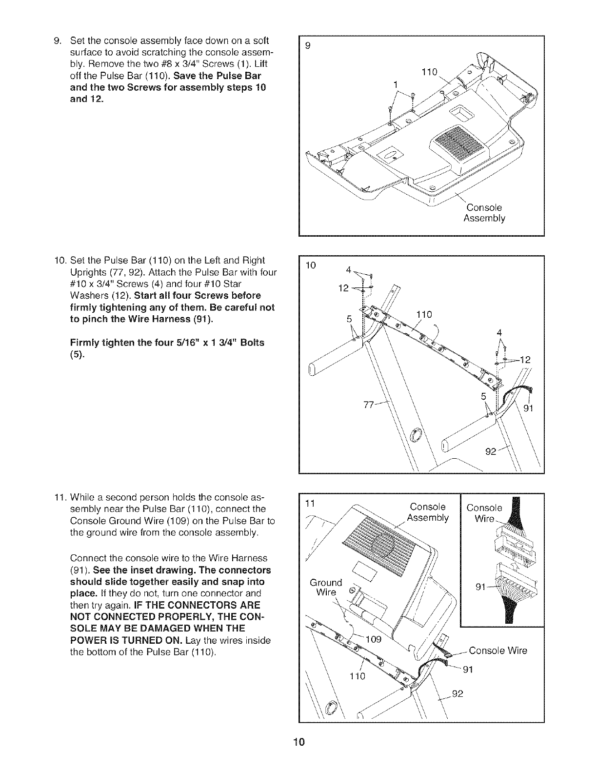
9. 9
Set the console assembly face down on a soft
surface to avoid scratching the console assem-
bly. Remove the two #8 x 3/4" Screws (1). Lift
off the Pulse Bar (110). Save the Pulse Bar
and the two Screws for assembly steps 10
and 12.
110
Console
Assembly
10. Set the Pulse Bar (110) on the Left and Right
Uprights (77, 92). Attach the Pulse Bar with four
#10 x 3/4" Screws (4) and four #10 Star
Washers (12). Start all four Screws before
firmly tightening any of them. Be careful not
to pinch the Wire Harness (91).
Firmly tighten the four 5/16" x 1 3/4" Bolts
(5).
10
110
11 Console Console
Assembly Wire_
11. While a second person holds the console as-
sembly near the Pulse Bar (110), connect the
Console Ground Wire (109) on the Pulse Bar to
the ground wire from the console assembly.
Connect the console wire to the Wire Harness
(91). See the inset drawing. The connectors
should slide together easily and snap into
place. If they do not, turn one connector and
then try again. IF THE CONNECTORS ARE
NOT CONNECTED PROPERLY, THE CON-
SOLE MAY BE DAMAGED WHEN THE
POWER IS TURNED ON. Lay the wires inside
the bottom of the Pulse Bar (110).
Ground
Wire
10
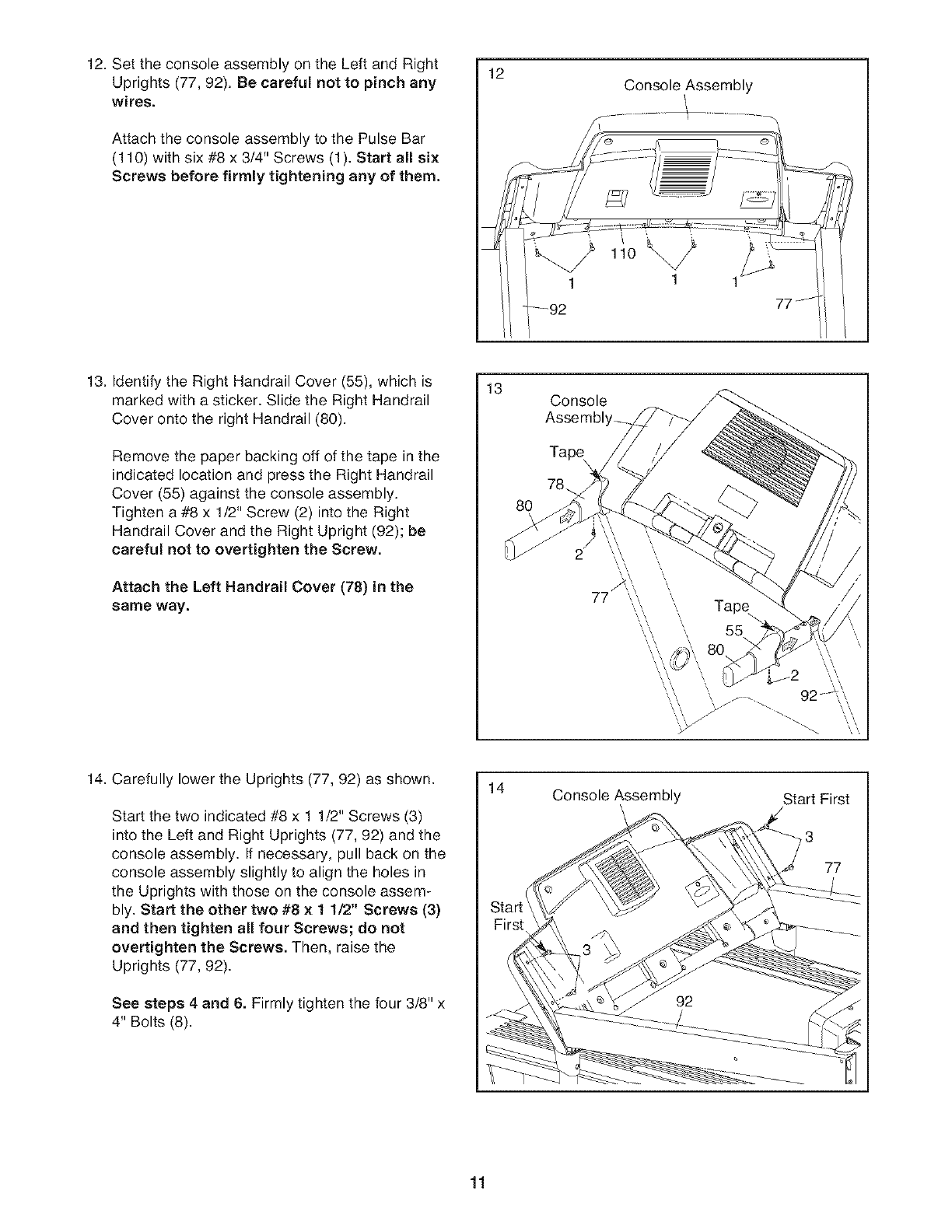
12. Set the console assembly on the Left and Right
Uprights (77, 92). Be careful not to pinch any
wires.
Attach the console assembly to the Pulse Bar
(110) with six #8 x 3/4" Screws (1). Start all six
Screws before firmly tightening any of them.
12 Console Assembly
1 1
13. Identify the Right Handrail Cover (55), which is
marked with a sticker. Slide the Right Handrail
Cover onto the right Handrail (80).
Remove the paper backing off of the tape in the
indicated location and press the Right Handrail
Cover (55) against the console assembly.
Tighten a #8 x 1/2" Screw (2) into the Right
Handrail Cover and the Right Upright (92); be
careful not to overtighten the Screw.
Attach the Left Handrail Cover (78) in the
same way.
13 Console
Assembl
14. Carefully lower the Uprights (77, 92) as shown.
Start the two indicated #8 x 1 1/2" Screws (3)
into the Left and Right Uprights (77, 92) and the
console assembly. If necessary, pull back on the
console assembly slightly to align the holes in
the Uprights with those on the console assem-
bly. Start the other two #8 x 1 1/2" Screws (3)
and then tighten all four Screws; do not
overtighten the Screws. Then, raise the
Uprights (77, 92).
See steps 4 and 8. Firmly tighten the four 3/8" x
4" Bolts (8).
14 Console Assembly Start First
3
77
11
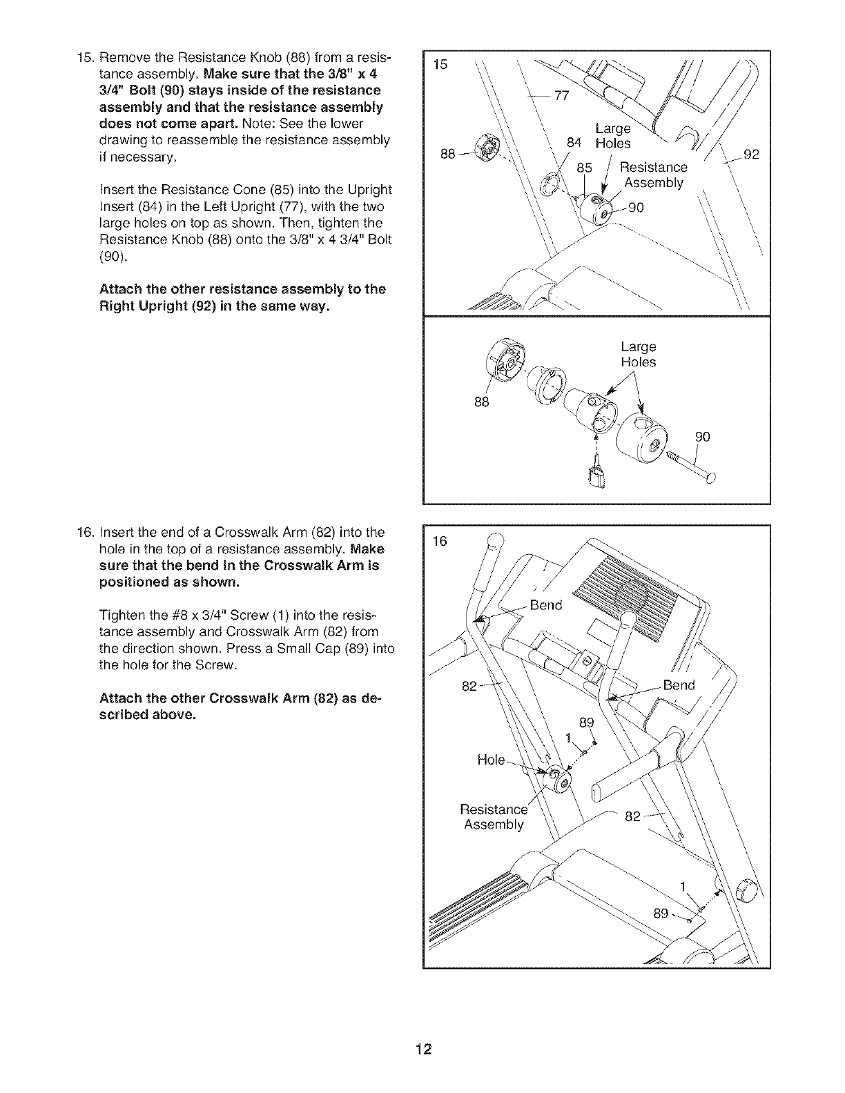
15. Remove the Resistance Knob (88) from a resis-
tance assembly, Make sure that the 3/8" x 4
3/4" Bomt(90) stays inside of the resistance
assembly and that the resistance assembly
does not come apart. Note: See the lower
drawing to reassemble the resistance assembly
if necessary.
Insert the Resistance Cone (85) into the Upright
Insert (84) in the Left Upright (77), with the two
large holes on top as shown. Then, tighten the
Resistance Knob (88) onto the 3/8" x 4 3/4" Bolt
(90).
Attach the other resistance assembly to the
Right Upright (92) in the same way.
15
\\
\\
88
-_- 77
Large
84 Holes
Resistance
Assembly
\\\
Large
Holes
90
16. Insert the end of a Crosswalk Arm (82) into the
hole in the top of a resistance assembly, Make
sure that the bend in the Crosswalk Arm is
positioned as shown.
Tighten the #8 x 3/4" Screw (1) into the resis-
tance assembly and Crosswalk Arm (82) from
the direction shown, Press a Small Cap (89) into
the hole for the Screw,
Attach the other Crosswalk Arm (82) as de-
scribed above.
16
12
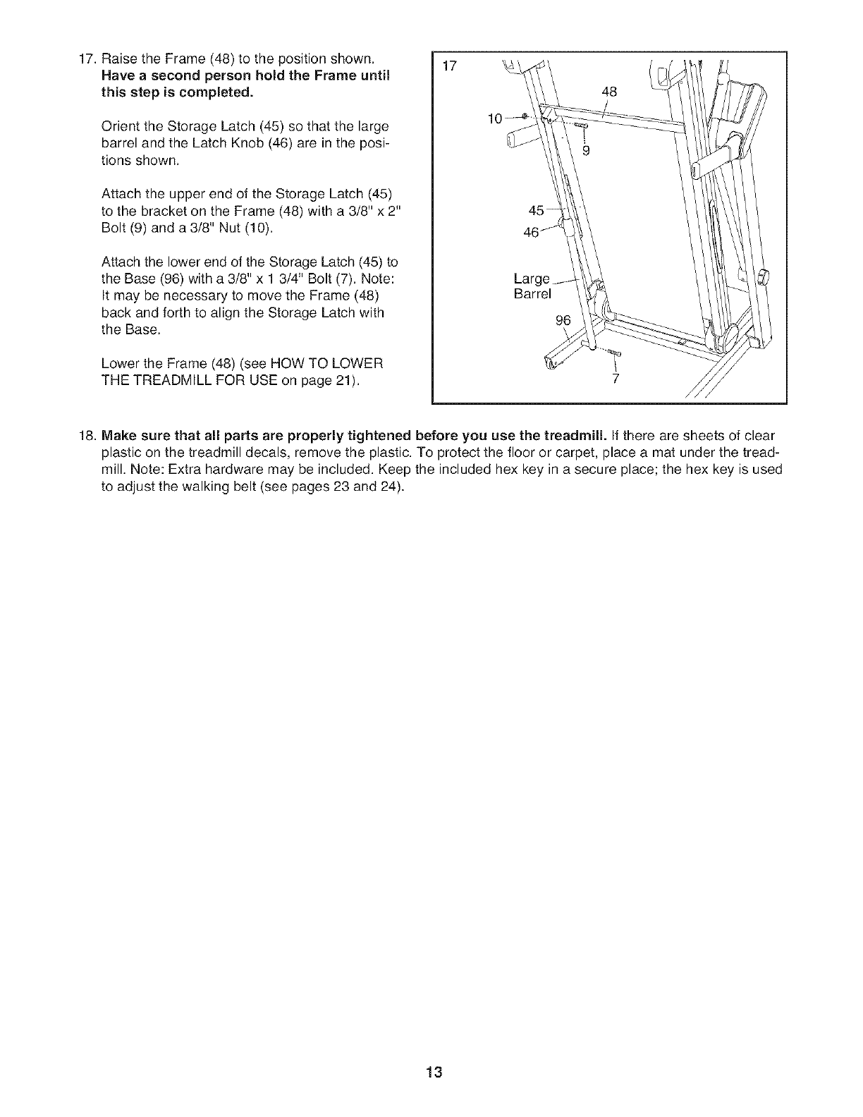
17. Raise the Frame (48) to the position shown.
Have a second person hold the Frame until
this step is completed.
Orient the Storage Latch (45) so that the large
barrel and the Latch Knob (46) are in the posi-
tions shown.
Attach the upper end of the Storage Latch (45)
to the bracket on the Frame (48) with a 3/8" x 2"
Bolt (9) and a 3/8" Nut (10).
Attach the lower end of the Storage Latch (45) to
the Base (96) with a 3/8" x 1 3/4" Bolt (7). Note:
It may be necessary to move the Frame (48)
back and forth to align the Storage Latch with
the Base.
Lower the Frame (48) (see HOW TO LOWER
THE TREADMILL FOR USE on page 21).
17
45
Barrel
96
48
7
18. Make sure that all parts are properly tightened before you use the treadmill. If there are sheets of clear
plastic on the treadmill decals, remove the plastic. To protect the floor or carpet, place a mat under the tread-
mill. Note: Extra hardware may be included. Keep the included hex key in a secure place; the hex key is used
to adjust the walking belt (see pages 23 and 24).
13
OPERATION AND ADJUSTMENT
THE PRE-LUBRICATED WALKING BELT
Your treadmill features a walking belt coated with high-
performance lubricant. IMPORTANT: Never apply sil-
icone spray or other substances to the walking
belt or the walking platform. Such substances will
deteriorate the walking belt and cause excessive
wear.
HOW TO PLUG IN THE POWER CORD
an equipment-grounding conductor and a grounding
plug. Plug the power cord into asurge suppressor,
and plug the surge suppressor into an appropriate
outlet that is properly installed and grounded in
accordance with all local codes and ordinances.
IMPORTANT: The treadmill is not compatible with
GFCI-equipped outlets.
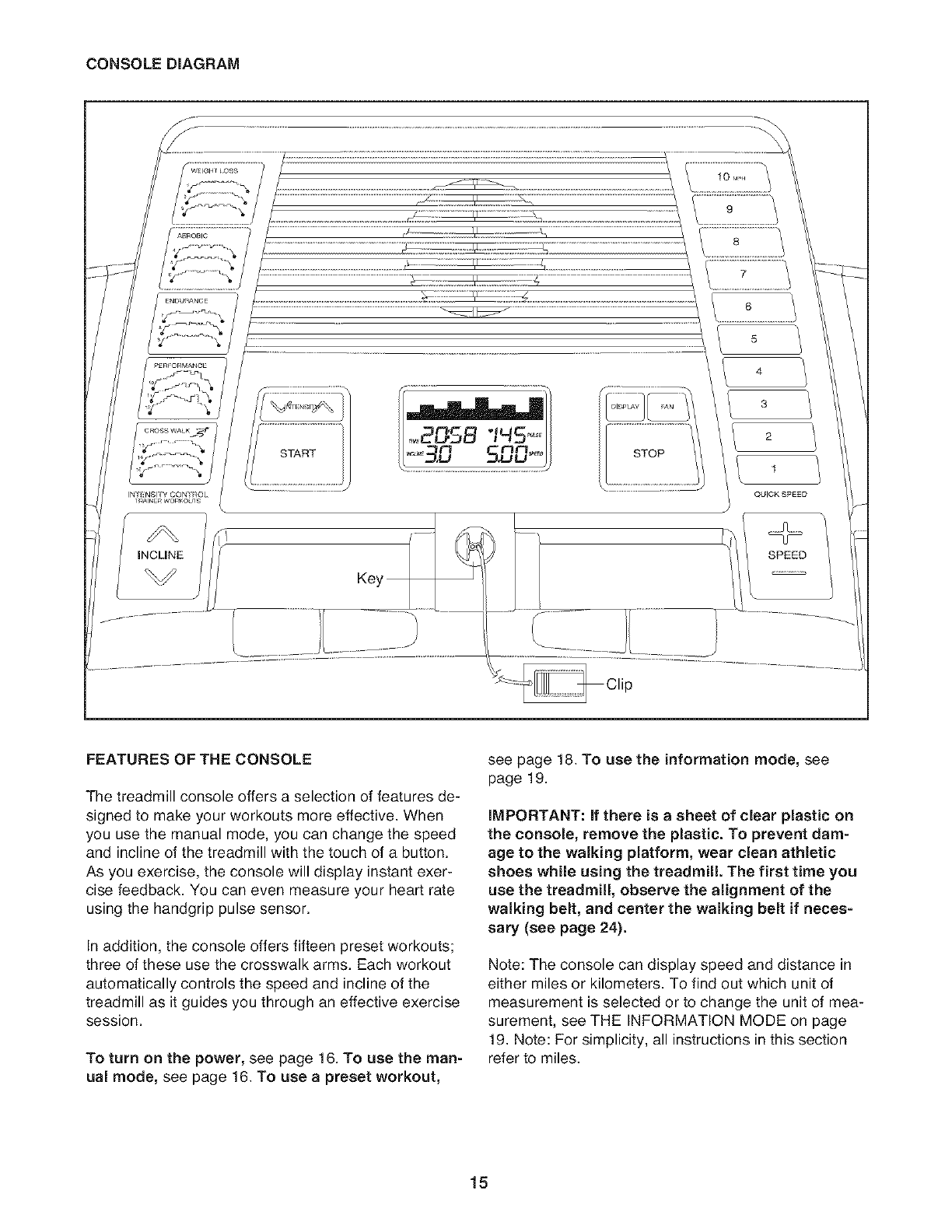
This product is for use on a nominal 120-volt circuit,
and has a grounding plug that looks like the plug illus-
trated in drawing 1 below. A temporary adapter that
looks like the adapter illustrated in drawing 2 may be
used to connect the surge suppressor to a 2-pole
receptacle as shown in drawing 2 if a properly
grounded outlet is not available.
Your treadmill, like any other type of sophisticated
electronic equipment, can be seriously damaged by
sudden voltage changes in your home's power.
Voltage surges, spikes, and noise interference can
result from weather conditions or from other appliances
being turned on or off. To decrease the possibility of
your treadmill being damaged, always use a surge
suppressor with your treadmill (see drawing 1 at
the right). To purchase a surge suppressor, see
your local Sears store or call the telephone number
on the back cover of this manual and order part
number 146148, or see your local electronics store.
Use only a single-outlet surge suppressor that is
UL 1449 listed as a transient voltage surge sup-
pressor (TVSS). The surge suppressor must have a
UL suppressed voltage rating of 400 volts or less
and a minimum surge dissipation of 450 joules.
The surge suppressor must be electrically rated for
120 volts AC and 15 amps. There must be a moni-
toring light on the surge suppressor to indicate
whether it is functioning properly. Failure to use a
properly functioning surge suppressor could result
in damage to the control system of the treadmill if
the control system is damaged, the walking belt
may slow, accelerate, or stop unexpectedly, which
may result in a fall and serious injury.
This product must be grounded. If it should malfunc-
tion or break down, grounding provides a path of least
resistance for electric current to reduce the risk of elec-
tric shock. This product is equipped with a cord having
2
Grounded Outlet Box
Suppressor
"< Grounding Pin
Grounding
Grounded Outlet Grounding Plug ''_---.
The temporary adapter should be used only until a
properly grounded outlet (drawing 1) can be installed
by a qualified electrician.
The green-colored rigid ear, lug, or the like extending
from the adapter must be connected to a permanent
ground such as a properly grounded outlet box cover.
Whenever the adapter is used it must be held in place
by a metal screw. Some 2-pole receptacle outlet box
covers are not grounded. Contact a qualified elec-
trician to determine if the outlet box cover is
grounded before using an adapter.
14
CONSOLE DIAGRAM
INT_:NSITYCONTROL
INCLINE
START STOP
5
4
3
2
1
QUICK SPEED
SPEED
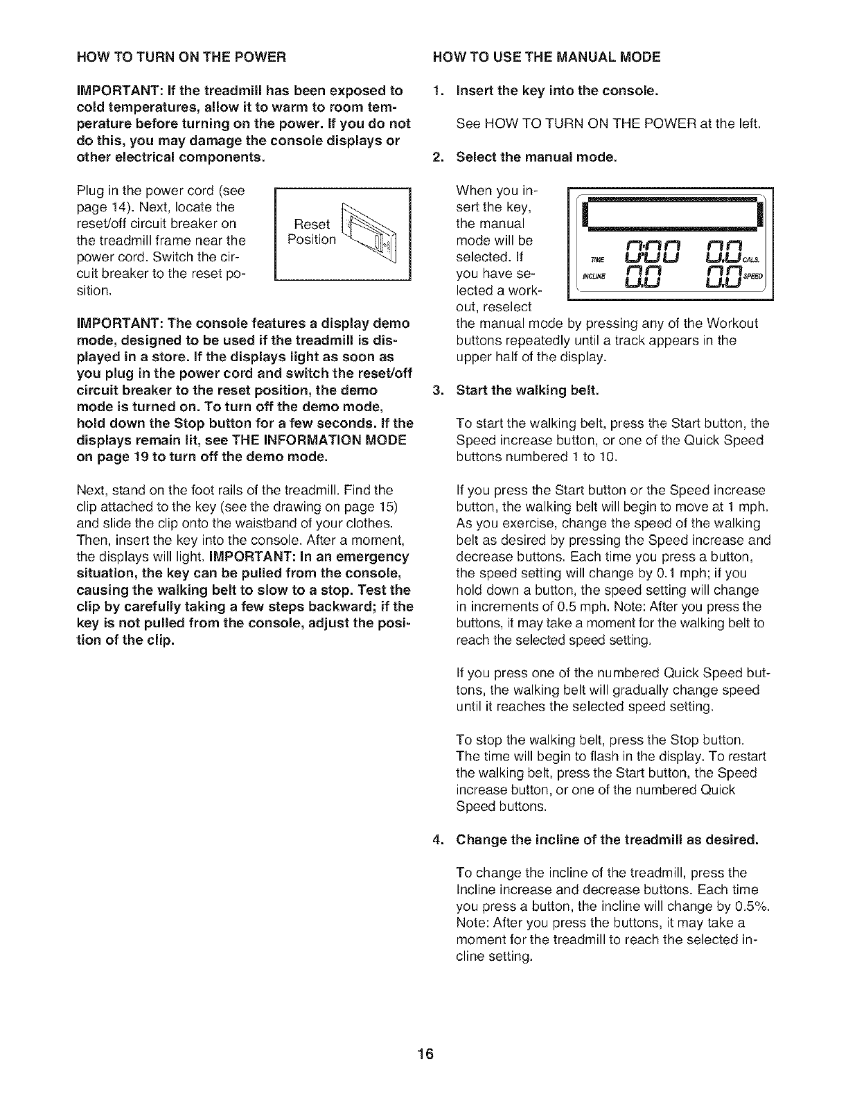
FEATURES OF THE CONSOLE
The treadmill console offers a selection of features de-
signed to make your workouts more effective. When
you use the manual mode, you can change the speed
and incline of the treadmill with the touch of a button.
As you exercise, the console will display instant exer-
cise feedback. You can even measure your heart rate
using the handgrip pulse sensor.
In addition, the console offers fifteen preset workouts;
three of these use the crosswalk arms. Each workout
automatically controls the speed and incline of the
treadmill as it guides you through an effective exercise
session.
To turn on the power, see page 16. To use the man-
ual mode, see page 16. To use a preset workout,
see page 18. To use the information mode, see
page 19.
iMPORTANT: if there is a sheet of clear plastic on
the console, remove the plastic. To prevent dam-
age to the walking platform, wear clean athletic
shoes while using the treadmill. The first time you
use the treadmill, observe the alignment of the
walking belt, and center the walking belt if neces-
sary (see page 24).
Note: The console can display speed and distance in
either miles or kilometers. To find out which unit of
measurement is selected or to change the unit of mea-
surement, see THE INFORMATION MODE on page
19. Note: For simplicity, all instructions in this section
refer to miles.
15
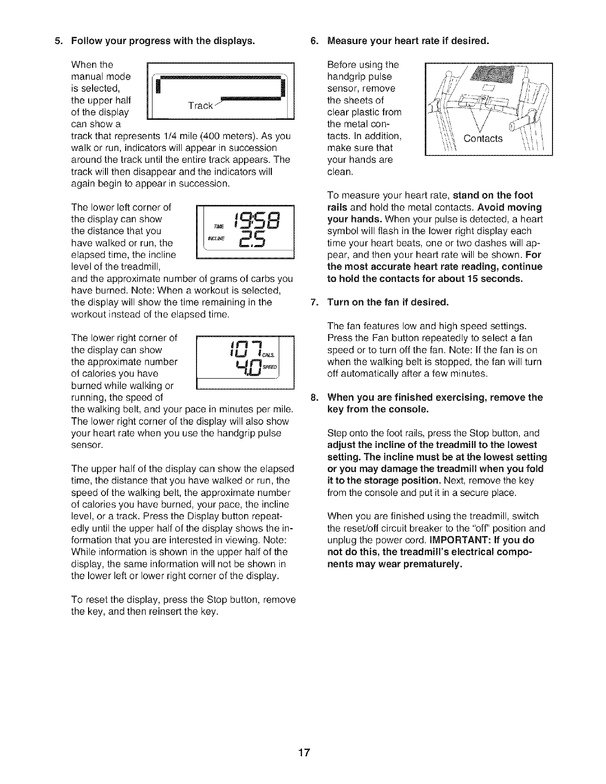
HOW TO TURN ON THE POWER
iMPORTANT: if the treadmill has been exposed to
cold temperatures, allow it to warm to room tern-
perature before turning on the power, if you do not
do this, you may damage the console displays or
other electrical components.
Plug in the power cord (see
page 14). Next, locate the
reset/off circuit breaker on
the treadmill frame near the
power cord. Switch the cir-
cuit breaker to the reset po-
sition.
Reset
Position
iMPORTANT: The console features a display derno
mode, designed to be used if the treadmill is dis=
played in a store, if the displays light as soon as
you plug in the power cord and switch the reset/off
circuit breaker to the reset position, the derno
mode is turned on. To turn off the derno mode,
hold down the Stop button for a few seconds, if the
displays remain lit, see THE INFORMATION MODE
on page 19 to turn off the derno mode.
Next, stand on the foot rails of the treadmill. Find the
clip attached to the key (see the drawing on page 15)
and slide the clip onto the waistband of your clothes.
Then, insert the key into the console. After a moment,
the displays will light. IMPORTANT: In an emergency
situation, the key can be pulled from the console,
causing the walking belt to slow to a stop. Test the
clip by carefully taking a few steps backward; if the
key is not pulled from the console, adjust the posi-
tion of the clip.
HOW TO USE THE MANUAL MODE
1. Insert the key into the console.
See HOW TO TURN ON THE POWER at the left.
2. Select the manual mode.
When you in-
sert the key,
the manual
mode will be
selected. If
you have se-
lected a work-
out, reselect
£=l,t=l lt-I N£=I
/_"_ U'ULJ U,U_L_
! u,u u,u
the manual mode by pressing any of the Workout
buttons repeatedly until a track appears in the
upper half of the display.
3. Start the walking belt.
To start the walking belt, press the Start button, the
Speed increase button, or one of the Quick Speed
buttons numbered 1 to 10.
If you press the Start button or the Speed increase
button, the walking belt will begin to move at 1 mph.
As you exercise, change the speed of the walking
belt as desired by pressing the Speed increase and
decrease buttons. Each time you press a button,
the speed setting will change by 0.1 mph; if you
hold down a button, the speed setting will change
in increments of 0.5 mph. Note: After you press the
buttons, it may take a moment for the walking belt to
reach the selected speed setting.
If you press one of the numbered Quick Speed but-
tons, the walking belt will gradually change speed
until it reaches the selected speed setting.
To stop the walking belt, press the Stop button.
The time will begin to flash in the display. To restart
the walking belt, press the Start button, the Speed
increase button, or one of the numbered Quick
Speed buttons.
4. Change the incline of the treadmill as desired.
To change the incline of the treadmill, press the
Incline increase and decrease buttons. Each time
you press a button, the incline will change by 0.5%.
Note: After you press the buttons, it may take a
moment for the treadmill to reach the selected in-
cline setting.
16
5. Follow your progress with the displays.
When the
manual mode
is selected,
the upper half
of the display
can show a
track that represents 1/4 mile (400 meters). As you
walk or run, indicators will appear in succession
around the track until the entire track appears. The
track will then disappear and the indicators will
again begin to appear in succession.
The lower left corner of
the display can show
the distance that you
have walked or run, the
elapsed time, the incline
level of the treadmill, ]
,£5B
B.5
and the approximate number of grams of carbs you
have burned. Note: When a workout is selected,
the display will show the time remaining in the
workout instead of the elapsed time.
The lower right corner of
the display can show
the approximate number
of calories you have
burned while walking or
running, the speed of
I ir1 I 1
lU I_ /
the walking belt, and your pace in minutes per mile.
The lower right corner of the display will also show
your heart rate when you use the handgrip pulse
sensor.
The upper half of the display can show the elapsed
time, the distance that you have walked or run, the
speed of the walking belt, the approximate number
of calories you have burned, your pace, the incline
level, or a track. Press the Display button repeat-
edly until the upper half of the display shows the in-
formation that you are interested in viewing. Note:
While information is shown in the upper half of the
display, the same information will not be shown in
the lower left or lower right corner of the display.
To reset the display, press the Stop button, remove
the key, and then reinsert the key.
6. Measure your heart rate if desired.
Before using the
handgrip pulse
sensor, remove
the sheets of
clear plastic from
the metal con-
tacts. In addition,
make sure that
your hands are
clean.
Contacts
To measure your heart rate, stand on the foot
rails and hold the metal contacts. Avoid moving
your hands. When your pulse is detected, a heart
symbol will flash in the lower right display each
time your heart beats, one or two dashes will ap-
pear, and then your heart rate will be shown. For
the most accurate heart rate reading, continue
to hold the contacts for about 15 seconds.
7. Turn on the fan if desired.
The fan features low and high speed settings.
Press the Fan button repeatedly to select a fan
speed or to turn off the fan. Note: If the fan is on
when the walking belt is stopped, the fan will turn
off automatically after a few minutes.
8. When you are finished exercising, remove the
key from the console.
Step onto the foot rails, press the Stop button, and
adjust the incline of the treadmill to the lowest
setting. The incline must be at the lowest setting
or you may damage the treadmill when you fold
it to the storage position. Next, remove the key
from the console and put it in a secure place.
When you are finished using the treadmill, switch
the reset/off circuit breaker to the "off" position and
unplug the power cord. IMPORTANT: If you do
not do this, the treadmilrs electrical compo-
nents may wear prematurely.
17
HOW TO USE A PRESET WORKOUT
1. insert the key into the console.
See HOW TO TURN ON THE POWER on page 16.
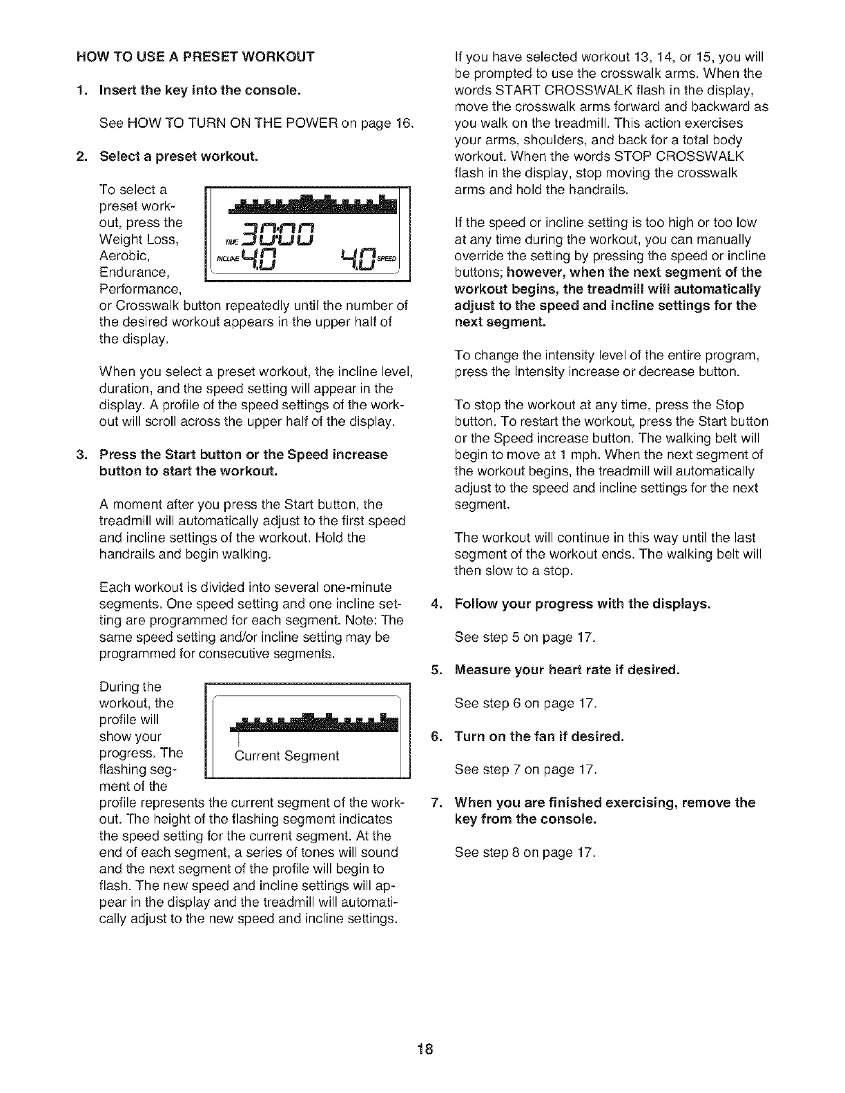
2. Select a preset workout.
To select a
preset work-
out, press the
Weight Loss,
Aerobic,
Endurance,
Performance,
7,LI 7,U J J
or Crosswalk button repeatedly until the number of
the desired workout appears in the upper half of
the display.
When you select a preset workout, the incline level,
duration, and the speed setting will appear in the
display. A profile of the speed settings of the work-
out will scroll across the upper half of the display.
3. Press the Start button or the Speed increase
button to start the workout.
A moment after you press the Start button, the
treadmill will automatically adjust to the first speed
and incline settings of the workout. Hold the
handrails and begin walking.
Each workout is divided into several one-minute
segments. One speed setting and one incline set-
ting are programmed for each segment. Note: The
same speed setting and/or incline setting may be
programmed for consecutive segments.
During the i
workout, the
profile will
show your
progress. The
flashing seg-
ment of the
Current Segment
profile represents the current segment of the work-
out. The height of the flashing segment indicates
the speed setting for the current segment. At the
end of each segment, a series of tones will sound
and the next segment of the profile will begin to
flash. The new speed and incline settings will ap-
pear in the display and the treadmill will automati-
cally adjust to the new speed and incline settings.
If you have selected workout 13, 14, or 15, you will
be prompted to use the crosswalk arms. When the
words START CROSSWALK flash in the display,
move the crosswalk arms forward and backward as
you walk on the treadmill. This action exercises
your arms, shoulders, and back for a total body
workout. When the words STOP CROSSWALK
flash in the display, stop moving the crosswalk
arms and hold the handrails.
If the speed or incline setting is too high or too low
at any time during the workout, you can manually
override the setting by pressing the speed or incline
buttons; however, when the next segment of the
workout begins, the treadmill will automatically
adjust to the speed and incline settings for the
next segment.
To change the intensity level of the entire program,
press the Intensity increase or decrease button.
To stop the workout at any time, press the Stop
button. To restart the workout, press the Start button
or the Speed increase button. The walking belt will
begin to move at 1 mph. When the next segment of
the workout begins, the treadmill will automatically
adjust to the speed and incline settings for the next
segment.
The workout will continue in this way until the last
segment of the workout ends. The walking belt will
then slow to a stop.
4. Follow your progress with the displays.
See step 5 on page 17.
5. Measure your heart rate if desired.
See step 6 on page 17.
6. Turn on the fan if desired.
See step 7 on page 17.
7. When you are finished exercising, remove the
key from the console.
See step 8 on page 17.
18
THE INFORMATION MODE
The console features an information mode that keeps
track of treadmill usage information. The information
mode also allows you to select miles or kilometers as
the unit of measurement, to adjust the contrast of the
display, and to turn on and turn off the demo mode.
To select the information mode, hold down the Stop
button, insert the key into the console, and then release
the Stop button. When the information mode is se-
lected, the following information will appear in the dis-
play:
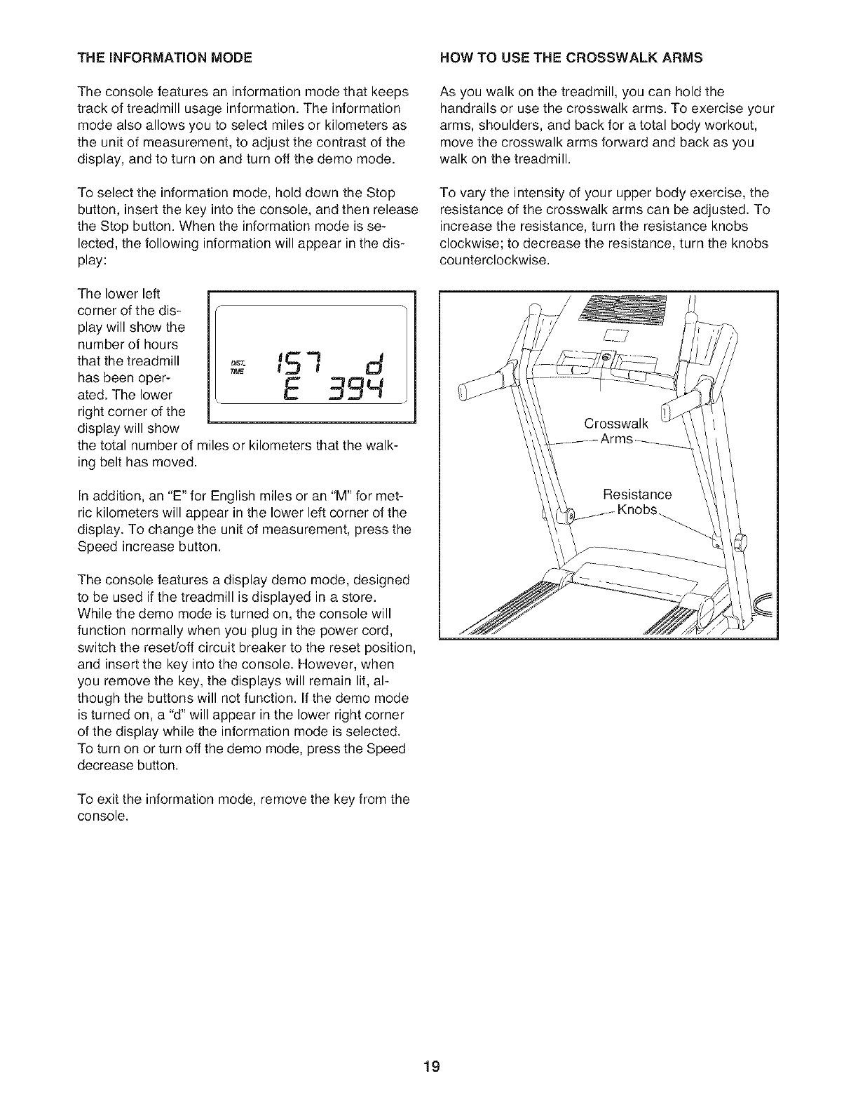
The lower left
corner of the dis-
play will show the
number of hours
that the treadmill
has been oper-
ated. The lower
right corner of the
display will show
the total number of miles or kilometers that the walk-
ing belt has moved.
151 d
E 39'4
In addition, an "E" for English miles or an "M" for met-
ric kilometers will appear in the lower left corner of the
display. To change the unit of measurement, press the
Speed increase button.
The console features a display demo mode, designed
to be used if the treadmill is displayed in a store.
While the demo mode is turned on, the console will
function normally when you plug in the power cord,
switch the reset/off circuit breaker to the reset position,
and insert the key into the console. However, when
you remove the key, the displays will remain lit, al-
though the buttons will not function. If the demo mode
is turned on, a "d" will appear in the lower right corner
of the display while the information mode is selected.
To turn on or turn off the demo mode, press the Speed
decrease button.
To exit the information mode, remove the key from the
console.
NOW TO USE THE CROSSWALK ARMS
As you walk on the treadmill, you can hold the
handrails or use the crosswalk arms. To exercise your
arms, shoulders, and back for a total body workout,
move the crosswalk arms forward and back as you
walk on the treadmill.
To vary the intensity of your upper body exercise, the
resistance of the crosswalk arms can be adjusted. To
increase the resistance, turn the resistance knobs
clockwise; to decrease the resistance, turn the knobs
counterclockwise.
19
HOW TO FOLD AND MOVE THE TREADMILL
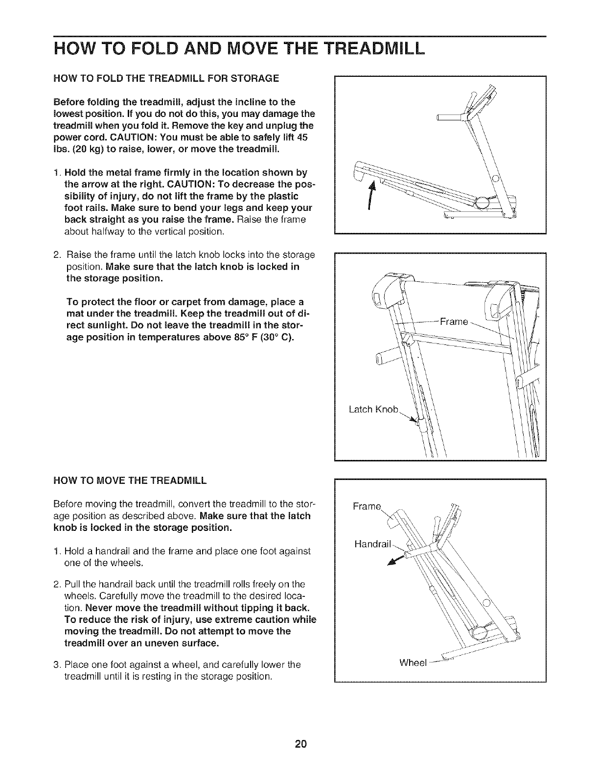
HOW TO FOLD THE TREADMILL FOR STORAGE
Before folding the treadmill, adjust the incline to the
lowest position, if you do not do this, you may damage the
treadmill when you fold it. Remove the key and unplug the
power cord. CAUTION: You must be able to safely lift 45
Ibs. (20 kg) to raise, lower, or move the treadmill.
1. Hold the metal frame firmly in the location shown by
the arrow at the right. CAUTION: To decrease the pos =
sibility of injury, do not lift the frame by the plastic
foot rails. Make sure to bend your legs and keep your
back straight as you raise the frame. Raise the frame
about halfway to the vertical position.
2. Raise the frame until the latch knob locks into the storage
position. Make sure that the latch knob is locked in
the storage position.
To protect the floor or carpet from damage, place a
mat under the treadmill Keep the treadmill out of dF
rect sunlight. Do not leave the treadmill in the stor-
age position in temperatures above 85° F (30° C).
L_ch Knob
HOW TO MOVE THE TREADMILL
Before moving the treadmill, convert the treadmill to the stor-
age position as described above. Make sure that the latch
knob is locked in the storage position.
1. Hold a handrail and the frame and place one foot against
one of the wheels.
2. Pull the handrail back until the treadmill rolls freely on the
wheels. Carefully move the treadmill to the desired loca-
tion. Never move the treadmill without tipping it back.
To reduce the risk of injury, use extreme caution while
moving the treadmill. Do not attempt to move the
treadmill over an uneven surface.
3. Place one foot against a wheel, and carefully lower the
treadmill until it is resting in the storage position.
Frame \
Handrail_
Wheel
\
\
20
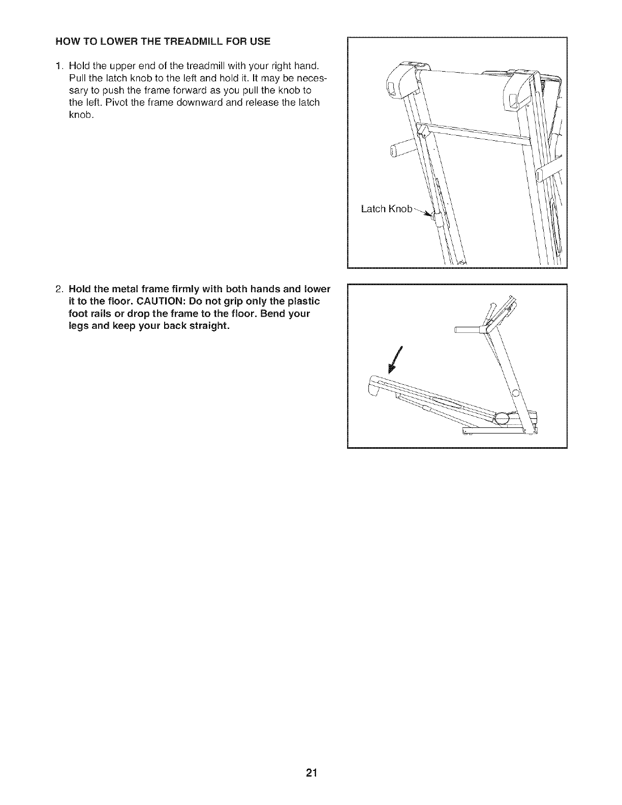
HOW TO LOWER THE TREADMILL FOR USE
1. Hold the upper end of the treadmill with your right hand,
Pull the latch knob to the left and hold it. It may be neces-
sary to push the frame forward as you pull the knob to
the left, Pivot the frame downward and release the latch
knob.
Latch Knob _-
2. Hold the metal frame firmly with both hands and lower
it to the floor. CAUTION: Do not grip only the plastic
foot rails or drop the frame to the floor. Bend your
legs and keep your back straight.
/
21
TROUBLESHOOTING
Most treadmill problems can be solved by following the steps below. Find the symptom that applies, and
follow the steps listed, if further assistance is needed, please see the back cover of this manual.
PROBLEM: The power does not turn on
SOLUTION: a. Make sure that the power cord is plugged into a surge suppressor, and that the surge suppressor
is plugged into a properly grounded outlet (see page 14). Use only a single-outlet surge suppres-
sor that meets all of the specifications described on page 14. IMPORTANT: The treadmill is not
compatible with GFCl-equipped outlets.
b. After the power cord has been plugged in, make sure that the key is inserted into the console.
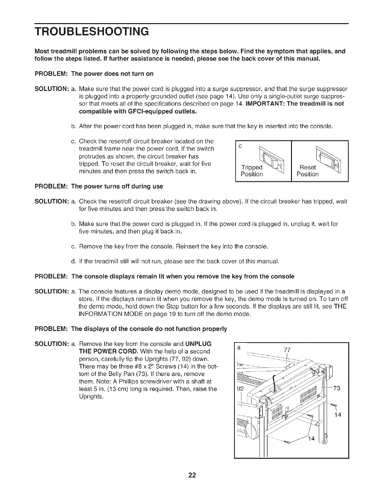
C. Check the reset/off circuit breaker located on the
treadmill frame near the power cord. If the switch
protrudes as shown, the circuit breaker has
tripped. To reset the circuit breaker, wait for five
minutes and then press the switch back in.
PROBLEM: The power turns off during use
c
Reset
Position Position
SOLUTION: a. Check the reset/off circuit breaker (see the drawing above). If the circuit breaker has tripped, wait
for five minutes and then press the switch back in.
b. Make sure that the power cord is plugged in. If the power cord is plugged in, unplug it, wait for
five minutes, and then plug it back in.
c. Remove the key from the console. Reinsert the key into the console.
d. If the treadmill still will not run, please see the back cover of this manual.
PROBLEM: The console displays remain lit when you remove the key from the console
SOLUTION: a. The console features a display demo mode, designed to be used if the treadmill is displayed in a
store. If the displays remain lit when you remove the key, the demo mode is turned on. To turn off
the demo mode, hold down the Stop button for a few seconds. If the displays are still lit, see THE
INFORMATION MODE on page 19 to turn off the demo mode.
PROBLEM: The displays of the console do not function properly
SOLUTION: a. Remove the key from the console and UNPLUG
THE POWER CORD. With the help of a second
person, carefully tip the Uprights (77, 92) down.
There may be three #8 x 2" Screws (14) in the bot-
tom of the Belly Pan (73). If there are, remove
them. Note: A Phillips screwdriver with a shaft at
least 5 in. (13 cm) long is required. Then, raise the
Uprights.
a 77
73
14
22
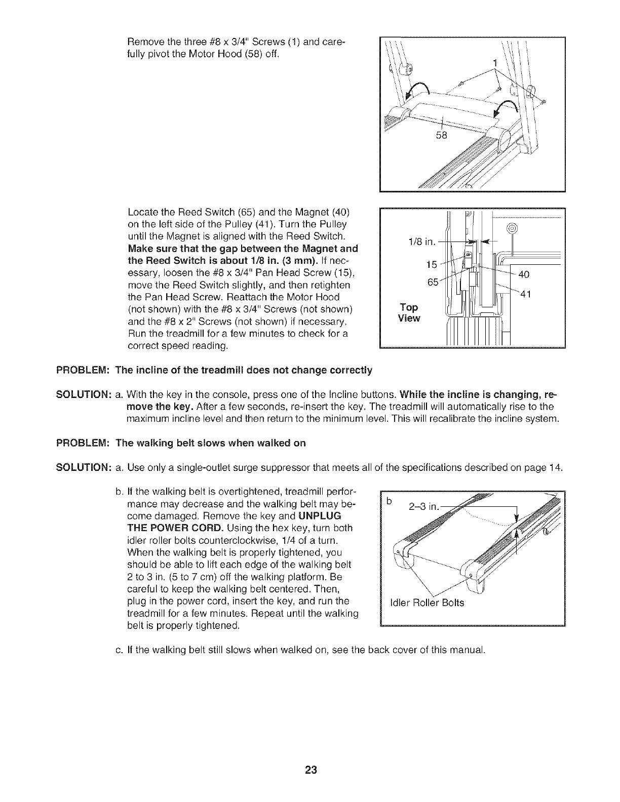
Remove the three #8 x 3/4" Screws (1) and care-
fully pivot the Motor Hood (58) off.
58
1
Locate the Reed Switch (65) and the Magnet (40)
on the left side of the Pulley (41). Turn the Pulley
until the Magnet is aligned with the Reed Switch.
Make sure that the gap between the Magnet and
the Reed Switch is about 1/8 in. (3 ram). If nec-
essary, loosen the #8 x 3/4" Pan Head Screw (15),
move the Reed Switch slightly, and then retighten
the Pan Head Screw. Reattach the Motor Hood
(not shown) with the #8 x 3/4" Screws (not shown)
and the #8 x 2" Screws (not shown) if necessary.
Run the treadmill for a few minutes to check for a
correct speed reading.
1/8 in.
15 _
65 /
Top
View
PROBLEM: The incline of the treadmill does not change correctly
SOLUTION: a. With the key in the console, press one of the Incline buttons. While the incline is changing, re-
move the key. After a few seconds, re-insert the key. The treadmill will automatically rise to the
maximum incline level and then return to the minimum level. This will recalibrate the incline system.
PROBLEM: The walking belt slows when walked on
SOLUTION: a. Use only a single-outlet surge suppressor that meets all of the specifications described on page 14.
b. If the walking belt is overtightened, treadmill perfor-
mance may decrease and the walking belt may be-
come damaged. Remove the key and UNPLUG
THE POWER CORD. Using the hex key, turn both
idler roller bolts counterclockwise, 1/4 of a turn.
When the walking belt is properly tightened, you
should be able to lift each edge of the walking belt
2 to 3 in. (5 to 7 cm) off the walking platform. Be
careful to keep the walking belt centered. Then,
plug in the power cord, insert the key, and run the
treadmill for a few minutes. Repeat until the walking
belt is properly tightened.
Idler Roller Bolts
c. If the walking belt still slows when walked on, see the back cover of this manual.
23
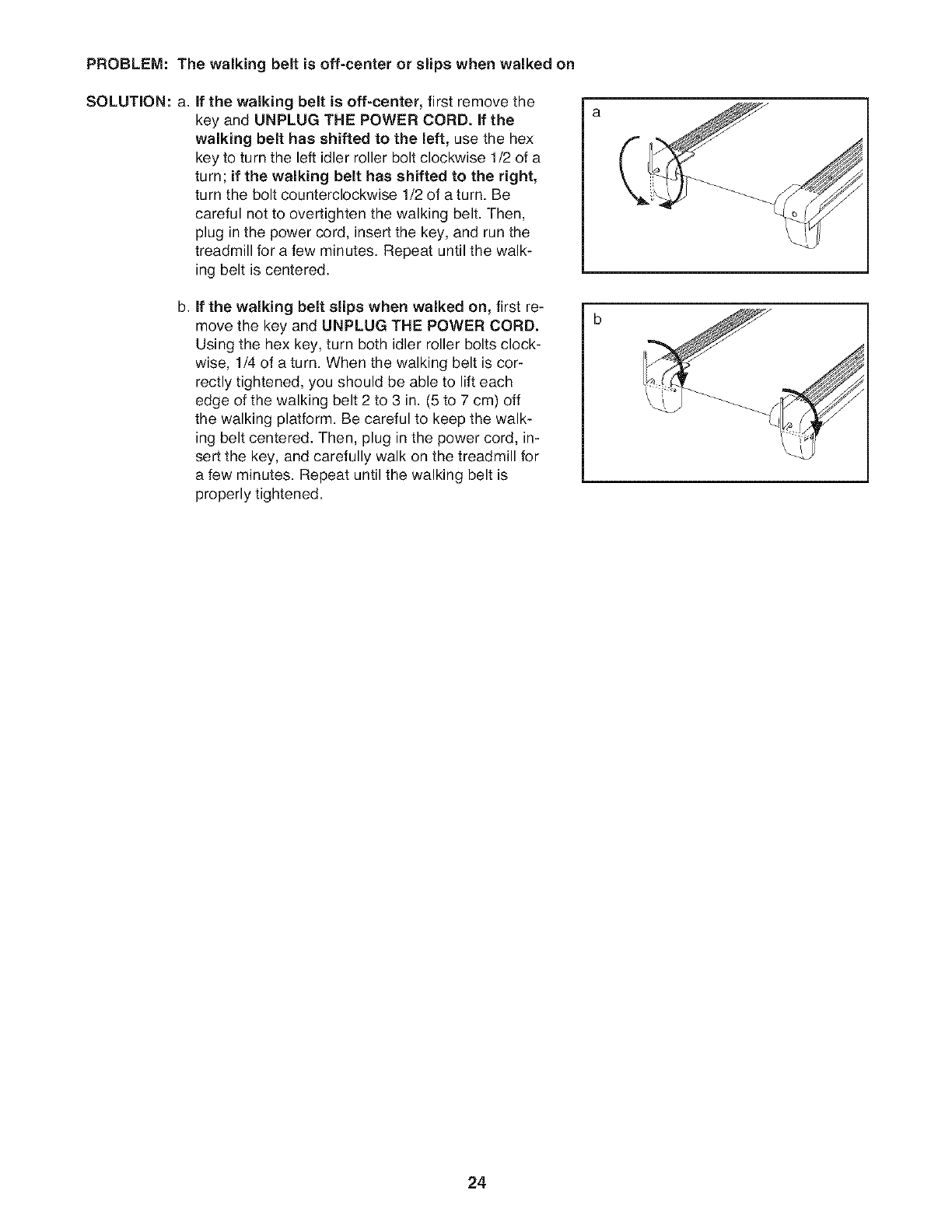
PROBLEM: The walking belt is off=center or slips when walked on
SOLUTION: a. If the walking belt is off=center, first remove the
key and UNPLUG THE POWER CORD. if the
walking belt has shifted to the left, use the hex
key to turn the left idler roller bolt clockwise 1/2 of a
turn; if the walking belt has shifted to the right,
turn the bolt counterclockwise 1/2 of atum. Be
careful not to overtighten the walking belt. Then,
plug in the power cord, insert the key, and run the
treadmill for a few minutes. Repeat until the walk-
ing belt is centered.
b. if the walking belt slips when walked on, first re-
move the key and UNPLUG THE POWER CORD.
Using the hex key, turn both idler roller bolts clock-
wise, 1/4 of a turn. When the walking belt is cor-
rectly tightened, you should be able to lift each
edge of the walking belt 2 to 3 in. (5 to 7 cm) off
the walking platform. Be careful to keep the walk-
ing belt centered. Then, plug in the power cord, in-
sert the key, and carefully walk on the treadmill for
a few minutes. Repeat until the walking belt is
properly tightened.
24
EXERCISE GUiDELiNES
Beforebeginningthis
or any exercise program, consult your physi-
cian. This is especially important for persons
over the age of 35 or persons with pre-exist-
ing health problems.
The pulse sensor is not a medical device.
Various factors may affect the accuracy of
heart rate readings. The pulse sensor is in-
tended only as an exercise aid in determining
heart rate trends in general.
These guidelines will help you to plan your exercise
program. For detailed exercise information, obtain a
reputable book or consult your physician. Remember,
proper nutrition and adequate rest are essential for
successful results.
EXERCISE INTENSITY
Whether your goal is to burn fat or to strengthen your
cardiovascular system, exercising at the proper inten-
sity is the key to achieving results. You can use your
heart rate as a guide to find the proper intensity level.
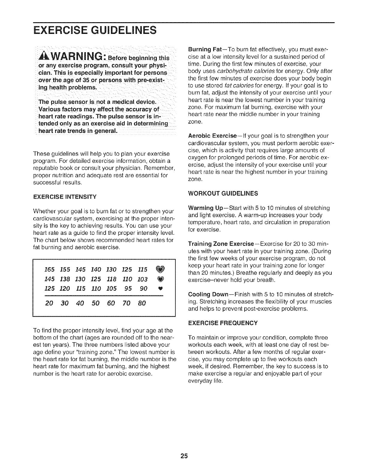
The chart below shows recommended heart rates for
fat burning and aerobic exercise.
165 155 145 140 130 125 1.1,5 _
145 138 130 125 118 110 103 _._)
125 120 115 110 105 95 90
20 30 40 50 60 70 80
To find the proper intensity level, find your age at the
bottom of the chart (ages are rounded off to the near-
est ten years). The three numbers listed above your
age define your "training zone." The lowest number is
the heart rate for fat burning, the middle number is the
heart rate for maximum fat burning, and the highest
number is the heart rate for aerobic exercise.
Burning Fat--To burn fat effectively, you must exer-
cise at a low intensity level for a sustained period of
time. During the first few minutes of exercise, your
body uses carbohydrate calories for energy, Only after
the first few minutes of exercise does your body begin
to use stored fat calories for energy. If your goal is to
burn fat, adjust the intensity of your exercise until your
heart rate is near the lowest number in your training
zone. For maximum fat burning, exercise with your
heart rate near the middle number in your training
zone.
Aerobic Exercise-- If your goal is to strengthen your
cardiovascular system, you must perform aerobic exer-
cise, which is activity that requires large amounts of
oxygen for prolonged periods of time. For aerobic ex-
ercise, adjust the intensity of your exercise until your
heart rate is near the highest number in your training
zone.
WORKOUT GUIDELINES
Warming Up--Start with 5 to 10 minutes of stretching
and light exercise. A warm-up increases your body
temperature, heart rate, and circulation in preparation
for exercise.
Training Zone Exercise--Exercise for 20 to 30 min-
utes with your heart rate in your training zone. (During
the first few weeks of your exercise program, do not
keep your heart rate in your training zone for longer
than 20 minutes.) Breathe regularly and deeply as you
exercise-never hold your breath.
Cooling Down--Finish with 5 to 10 minutes of stretch-
ing. Stretching increases the flexibility of your muscles
and helps to prevent post-exercise problems.
EXERCISE FREQUENCY
To maintain or improve your condition, complete three
workouts each week, with at least one day of rest be-
tween workouts. After a few months of regular exer-
cise, you may complete up to five workouts each
week, if desired. Remember, the key to success is to
make exercise a regular and enjoyable part of your
everyday life.
25
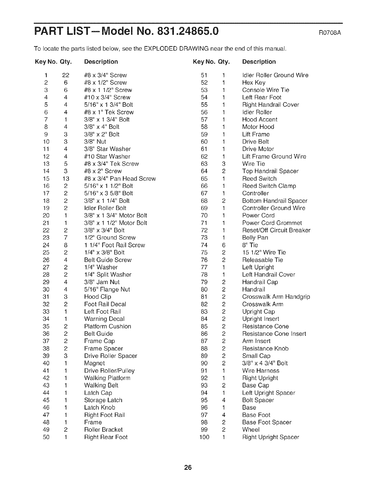
PART LIST--IVlodel No. 831.24865.0 RO7OSA
To locate the parts listed below, see the EXPLODED DRAWING near the end of this manual,
Key No. Qty. Description Key No. Qty. Description
1 22 #8 x 3/4" Screw 51 1 Idler Roller Ground Wire
2 6 #8 x 1/2" Screw 52 1 Hex Key
3 6 #8 x 1 1/2" Screw 53 1 Console Wire Tie
4 4 #10 x 3/4" Screw 54 1 Left Rear Foot
5 4 5/16" x 1 3/4" Bolt 55 1 Right Handrail Cover
6 4 #8 x 1" Tek Screw 56 1 Idler Roller
7 1 3/8" x 1 3/4" Bolt 57 1 Hood Accent
8 4 3/8" x 4" Bolt 58 1 Motor Hood
9 3 3/8" x 2" Bolt 59 1 Lift Frame
10 3 3/8" Nut 60 1 Drive Belt
11 4 3/8" Star Washer 61 1 Drive Motor
12 4 #10 Star Washer 62 1 Lift Frame Ground Wire
13 5 #8 x 3/4" Tek Screw 63 3 Wire Tie
14 3 #8 x 2" Screw 64 2 Top Handrail Spacer
15 13 #8 x 3/4" Pan Head Screw 65 1 Reed Switch
16 2 5/16" x 1 1/2" Bolt 66 1 Reed Switch Clamp
17 2 5/16" x 3 5/8" Bolt 67 1 Controller
18 2 3/8" x 1 1/4" Bolt 68 2 Bottom Handrail Spacer
19 2 Idler Roller Bolt 69 1 Controller Ground Wire
20 1 3/8" x 1 3/4" Motor Bolt 70 1 Power Cord
21 1 3/8" x 1 1/2" Motor Bolt 71 1 Power Cord Grommet
22 2 3/8" x 3/4" Bolt 72 1 Reset/Off Circuit Breaker
23 7 1/2" Ground Screw 73 1 Belly Pan
24 8 1 1/4" Foot Rail Screw 74 6 8" Tie
25 2 1/4" x 3/8" Bolt 75 2 15 1/2" Wire Tie
26 4 Belt Guide Screw 76 2 Releasable Tie
27 2 1/4" Washer 77 1 Left Upright
28 2 1/4" Split Washer 78 1 Left Handrail Cover
29 4 3/8" Jam Nut 79 2 Handrail Cap
30 4 5/16" Flange Nut 80 2 Handrail
31 3 Hood Clip 81 2 Crosswalk Arm Handgrip
32 2 Foot Rail Decal 82 2 Crosswalk Arm
33 1 Left Foot Rail 83 2 Upright Cap
34 1 Warning Decal 84 2 Upright Insert
35 2 Platform Cushion 85 2 Resistance Cone
36 2 Belt Guide 86 2 Resistance Cone Insert
37 2 Frame Cap 87 2 Arm Insert
38 2 Frame Spacer 88 2 Resistance Knob
39 3 Drive Roller Spacer 89 2 Small Cap
40 1 Magnet 90 2 3/8" x 4 3/4" Bolt
41 1 Drive Roller/Pulley 91 1 Wire Harness
42 1 Walking Platform 92 1 Right Upright
43 1 Walking Belt 93 2 Base Cap
44 1 Latch Cap 94 1 Left Upright Spacer
45 1 Storage Latch 95 4 Bolt Spacer
46 1 Latch Knob 96 1 Base
47 1 Right Foot Rail 97 4 Base Foot
48 1 Frame 98 2 Base Foot Spacer
49 2 Roller Bracket 99 2 Wheel
50 1 Right Rear Foot 100 1 Right Upright Spacer
26

Key No. Qty. Description Key No. Qty. Description
101 2 Caution Decal
102 1 Incline Motor
103 1 Incline Motor Spacer
104 1 Fan
105 1 Console
106 1 Key/Clip
107 1 Console Back
108 1 Accessory Door
109
110
1 Console Ground Wire
1 Pulse Bar
- 8" Blue Wire, M/F
- 10" Blue Wire, 2F
- 12" Red Wire, M/F
- 10" Black Wire, M/F
- 4" Green Wire, M/R
- User's Manual
Note: Specifications are subject to change without notice. See the back cover of this manual for information about
ordering replacement parts. If a part is missing, call 1-888-533-1333. *These parts are not illustrated.
27
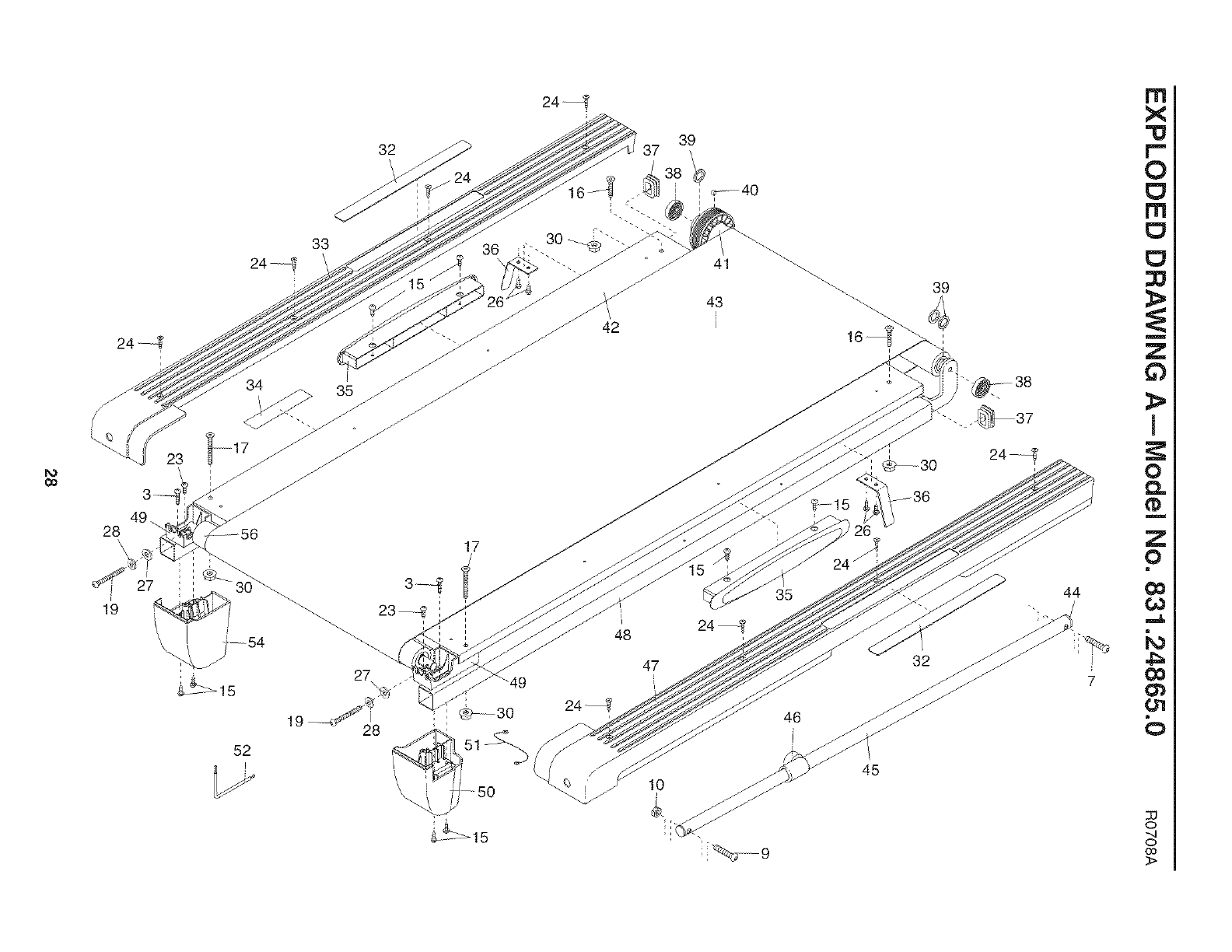
b_
CO
28\
19
32
33 36
23
24_
39
/
/
_442 43
/
17
27 i
\
_15
_15
52
_\ 39
35
32
46
45
44
7
rrl
X
r"-
0
rrl
m
Z
0
I
0
0,,.
m
Z
o
O_
,,,,,,&
k_
0
o
..q
o
0o
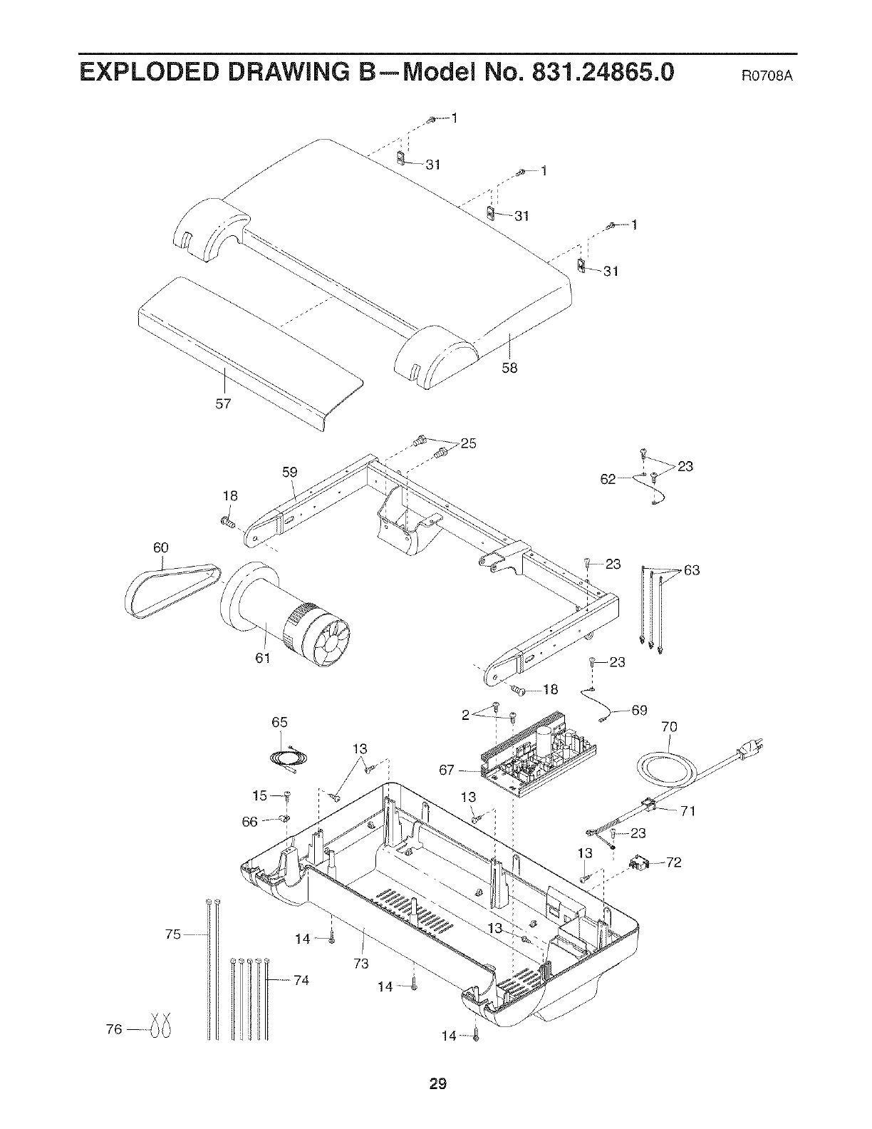
EXPLODED DRAWING B--Model No. 831.24865.0 RO7OSA
58
57
18
59
6O
61
65
66
75 ....... 14 4
73 14
14
29
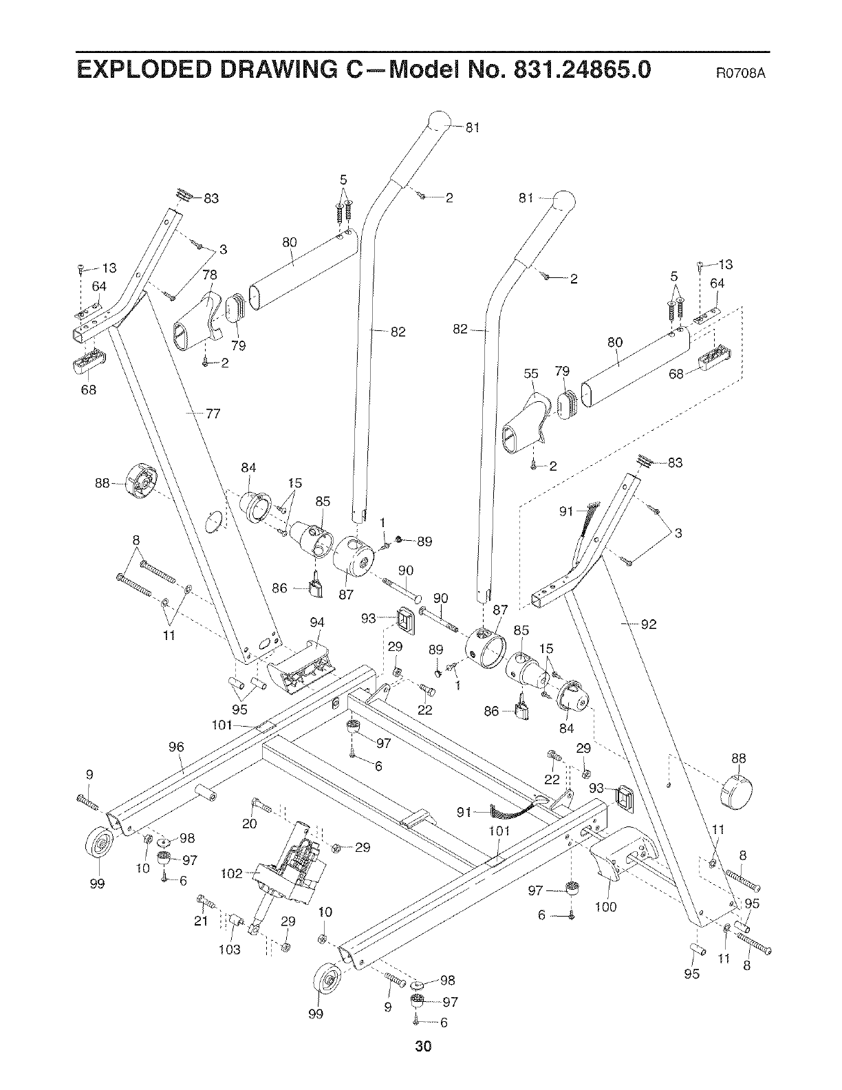
EXPLODED DRAWING C--lVlodel No. 831.24865.0 RO7OSA
5
/_ 83 2
79
68
99
77
84
8
95
96
2O
21
103
80
15
29
90
87 90
94
i29 89
1
22
i
i
10
101
81
55
85
15
6100
95
11
8
18
3O
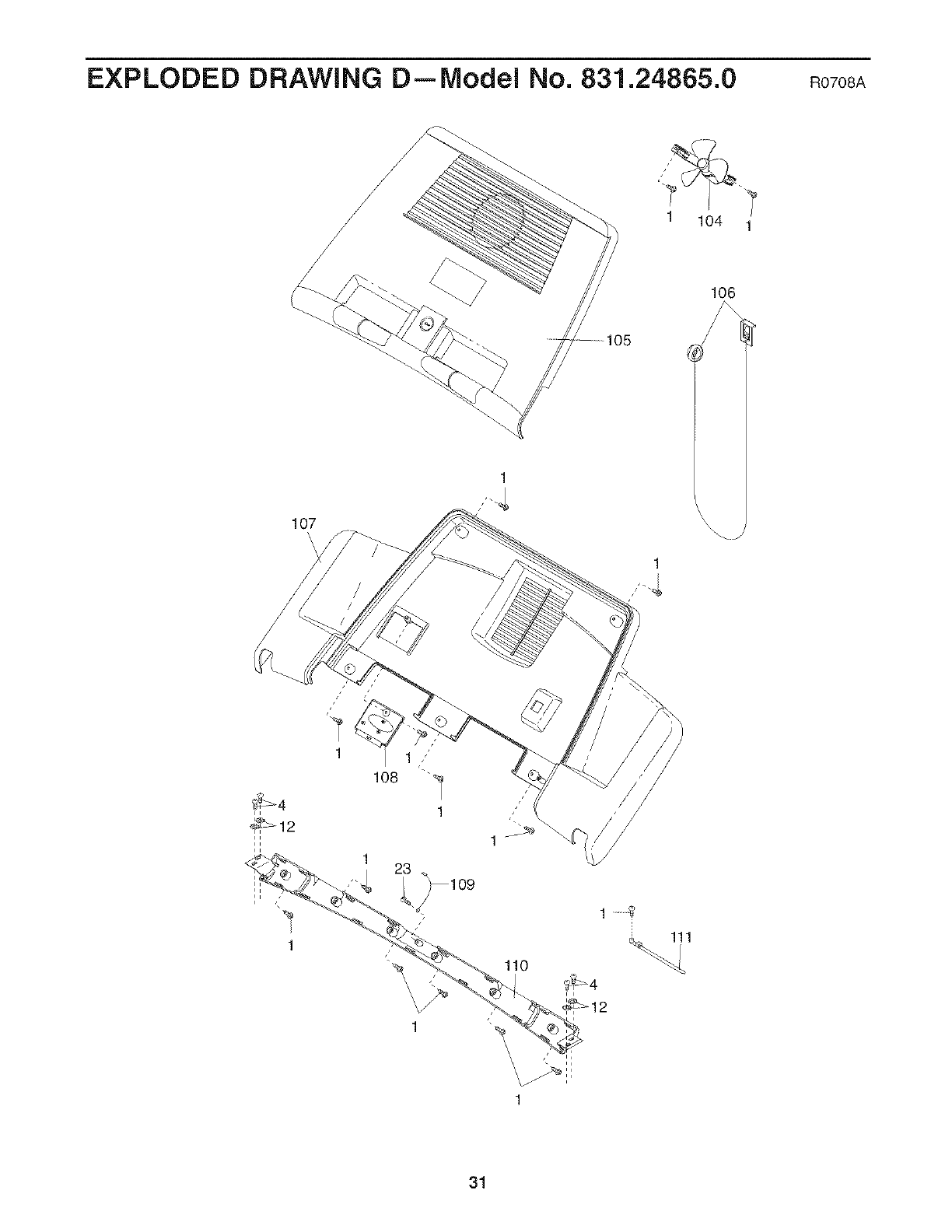
EXPLODED DRAWING D--Model No. 831.24865.0 RO7OSA
1 104 1
106
107
'\
1
1
1
_o8
1
1
31

!!!!!!!!!!!!_
ililililililililiiii(ii
!!!!!!!!!!!!i
Your Home
For repair--in your home--of all major brand appliances, lawn and garden equipment,
or heating and cooling systems, no matter who made it, no matter who sold it!
For the replacement parts, accessories, and user's manuals that you need to do-it-yourself.
For Sears professional installation of home appliances
and items like garage door openers and water heaters.
1-800-4-MY-HOME ®(1-800-469-4663)
Call anytime, day or night (U,S,A, and Canada)
www.sears.com www.sears.ca
Our Home
For repair of carry-in items like vacuums, lawn equipment,
and electronics, call or go on-line for the location of your nearest
Sears Parts & Repair Center.
1-800-488-1222 Call anytime, day or night (U,S,A, only)
www.sears.com
To purchase a protection agreement (U.S.A.)
or maintenance agreement (Canada) on a product serviced by Sears:
1-800-827-6655 (U.S.A.) 1-800-361-6665 (Canada)
Para pedir servicio de reparacion a domicilio, y para ordenar piezas:
iiiiiiiiiiiii
iiiiiiiiiiiii
iiiiiiiiiiiii
iiiiiiiiiiiii
iiiiiiiiiiiii
® Registered Trademark /TM Trademark /s_ Service Mark of Sears Brands, LLC
TM SM
® Marca Registrada /Marca de F&bdca /Marca de Servicio de Sears Brands, LLC
S90 DAY FULL WARRANTY
If this Sears Treadmill Exerciser fails due to a defect in material or workmanship within 90 days of the
date of purchase, call 1-8OO-4-MY-HOME ®(1-800-469-4663) to arrange for free repair (or replacement if
repair proves impossible). The drive motor is warranted for 25 years from the date of purchase.
This warranty does not apply when the Treadmill Exerciser is used commercially or for rental purposes.
This warranty gives you specific legal rights, and you may also have other rights which vary from state to
state.
Sears, Roebuck and Co., Hoffman Estates, IL 60179
Part No. 267488 RO708A Printed in USA © 2008 ICON IP, Inc.
