Proform 831286451 User Manual PRO FORM XP 160 Manuals And Guides L0801729
PROFORM Elliptical Manual L0801729 PROFORM Elliptical Owner's Manual, PROFORM Elliptical installation guides
XP 160 831.28645.1 L0801729
User Manual: Proform 831286451 831286451 PROFORM PRO-FORM XP 160 - Manuals and Guides View the owners manual for your PROFORM PRO-FORM XP 160 #831286451. Home:Fitness Equipment Parts:Proform Parts:Proform PRO-FORM XP 160 Manual
Open the PDF directly: View PDF ![]() .
.
Page Count: 28

Model No. 831.28645.1
Serial No.
Serial Number
Decal
(on underside
of frame)
• Assembly
•Operation
•Maintenance
•Part List and Drawing
ELLIPTICAL EXERCISER
User's Manual
Sears, Roebuck and Co., Hoffman Estates, IL 60179
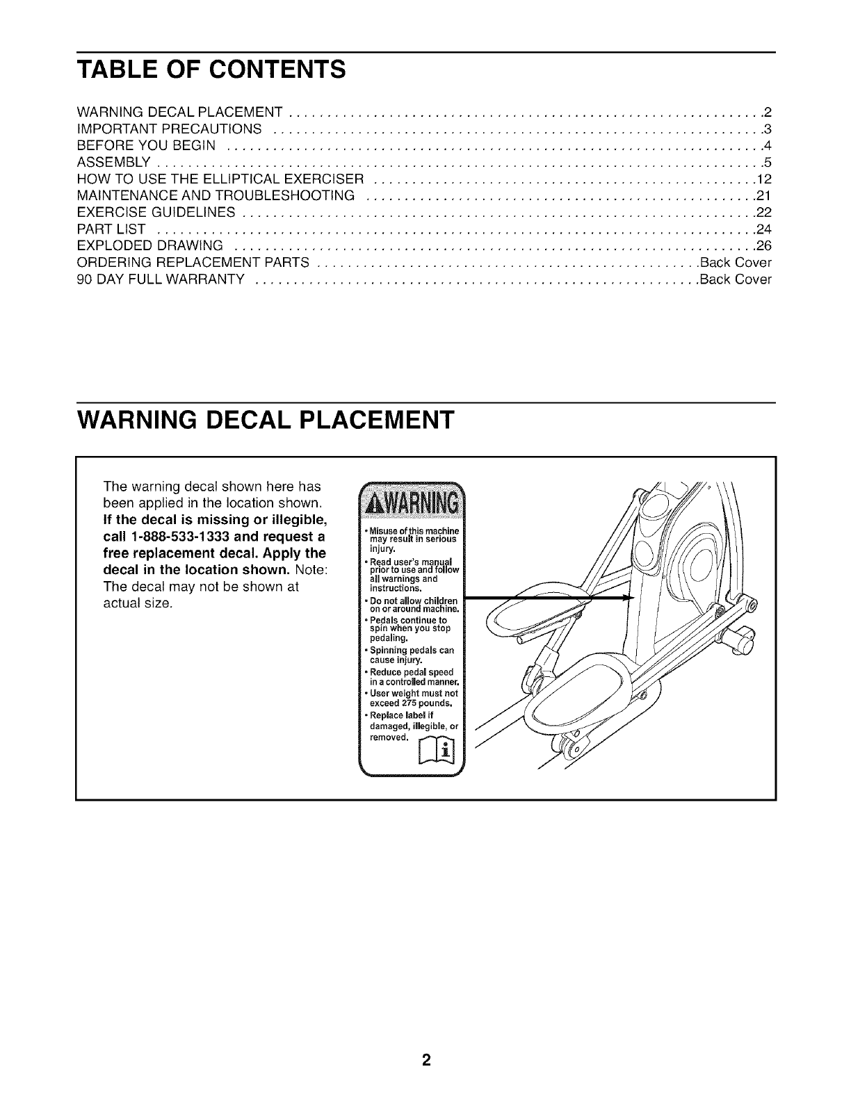
TABLE OF CONTENTS
WARNING DECAL PLACEMENT .............................................................. 2
IMPORTANT PRECAUTIONS ................................................................ 3
BEFORE YOU BEGIN ...................................................................... 4
ASSEMBLY ............................................................................... 5
HOW TO USE THE ELLIPTICAL EXERCISER .................................................. 12
MAINTENANCE AND TROUBLESHOOTING ................................................... 21
EXERCISE GUIDELINES ................................................................... 22
PART LIST .............................................................................. 24
EXPLODED DRAWING .................................................................... 26
ORDERING REPLACEMENT PARTS .................................................. Back Cover
90 DAY FULL WARRANTY .......................................................... Back Cover
WARNING DECAL PLACEMENT
The warning decal shown here has
been applied in the location shown.
If the decal is missing or illegible,
call 1-888-533-1333 and request a
free replacement decal. Apply the
decal in the location shown, Note:
The decal may not be shown at
actual size.
2
IMPORTANT PRECAUTIONS
BEFORE YOU BEGIN
Thank you for selecting the new PROFORM ®XP 160
elliptical exerciser. The PROFORM XP 160 elliptical
exerciser provides a wide array of features designed
to make your workouts at home more effective and
enjoyable.
For your benefit, read this manual carefully before
you use the elliptical exerciser, If you have ques-
tions after reading this manual, please see the back
cover of this manual. To help us assist you, note the
product model number and serial number before con-
tacting us. The model number and the location of the
serial number decal are shown on the front cover of
this manual.
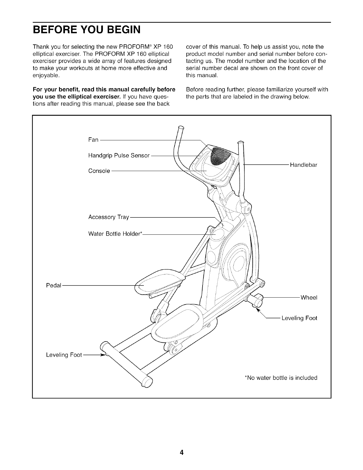
Before reading further, please familiarize yourself with
the parts that are labeled in the drawing below.
Fan
Handgrip Pulse Sensor
Console Handlebar
Accessory Tray
Water Bottle Holder*
Pedal
Wheel
Leveling Foot
Leveling Foot
*No water bottle is included
4
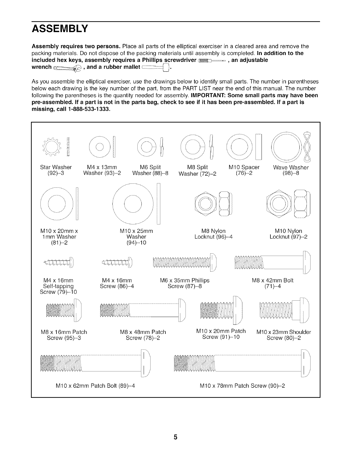
ASSEMBLY
Assembly requires two persons. Place all parts of the elliptical exerciser in a cleared area and remove the
packing materials. Do not dispose of the packing materials until assembly is completed. In addition to the
included hex keys, assembly requires a Phillips screwdriver _x_==_, an adjustable
...... _ rubber mallet c:_--_,
wrench ©_, and a 4,
As you assemble the elliptical exerciser, use the drawings below to identify small parts. The number in parentheses
below each drawing is the key number of the part, from the PART LIST near the end of this manual. The number
following the parentheses is the quantity needed for assembly. IMPORTANT: Some small parts may have been
pre-assembled. If a part is not in the parts bag, check to see if it has been pre-assembled. If a part is
missing, call 1-888-533-1333.
Star Washer M4 x 13mm M6 Split M8 Split M10 Spacer Wave Washer
(92)-3 Washer (93)-2 Washer (88)-8 Washer (72)-2 (76)-2 (98)-8
O}
M10 x 20mm x
1mm Washer
(81)-2
M10 x 25mm
Washer
(94)-10
M8 Nylon
Locknut (96)-4 M10 Nylon
Locknut (97)-2
M4 x 16mm
Self-tapping
Screw (79)-10
M4 x 16mm
Screw (86)-4 M6 x 35mm Phillips
Screw (87)-8 M8 x 42mm Bolt
(71)-4
M8 x 16mm Patch
Screw (95)-3 M8 x 48mm Patch
Screw (78)-2
M10 x 20mm Patch
Screw (91)-10 M10 x 23mm Shoulder
Screw (80)-2
M10 x 62mm Patch Bolt (89)-4 M10 x 78mm Patch Screw (90)-2

1.
Orient the the Front Stabilizer (35) as shown.
Attach the two Wheels (25) to the Front Stabilizer
with two M10 x 62mm Patch Bolts (89) and two
M10 Nylon Locknuts (97).
Attach two Feet (26) to the underside of the
Front Stabilizer (35).
25
25_
97
89
35
Have a second person tip the Frame (2) back-
ward. Attach the Front Stabilizer (35) to the
Frame with two M10 x 78mm Patch Screws (90).
90
3. Orient the Base (1) near the Frame (2) as
shown. See the inset drawing. Attach two Feet
(26) to the underside of the Base.
Have a second person tip the Frame (2) forward.
Insert the Base (1) into the Frame. Attach the
Base with two M10 x 62mm Patch Bolts (89), two
M10 Spacers (76), two M8 x 48mm Patch
Screws (78), and two M8 Split Washers (72).
_)?_26
26
6
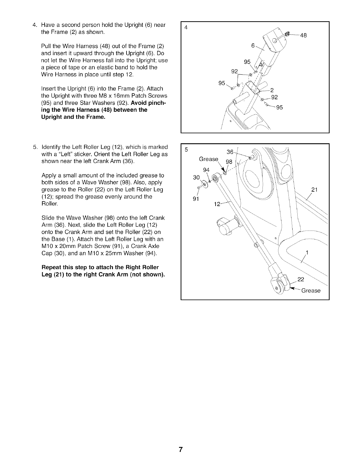
4. Have a second person hold the Upright (6) near
the Frame (2) as shown.
Pull the Wire Harness (48) out of the Frame (2)
and insert it upward through the Upright (6). Do
not let the Wire Harness fall into the Upright; use
a piece of tape or an elastic band to hold the
Wire Harness in place until step 12.
Insert the Upright (6) into the Frame (2). Attach
the Upright with three M8 x 16mm Patch Screws
(95) and three Star Washers (92). Avoid pinch-
ing the Wire Harness (48) between the
Upright and the Frame.
95
.Identify the Left Roller Leg (12), which is marked
with a "Left" sticker. Orient the Left Roller Leg as
shown near the left Crank Arm (36).
Apply a small amount of the included grease to
both sides of a Wave Washer (98). Also, apply
grease to the Roller (22) on the Left Roller Leg
(12); spread the grease evenly around the
Roller.
Slide the Wave Washer (98) onto the left Crank
Arm (36). Next, slide the Left Roller Leg (12)
onto the Crank Arm and set the Roller (22) on
the Base (1). Attach the Left Roller Leg with an
M10 x 20mm Patch Screw (91), a Crank Axle
Cap (30), and an M10 x 25mm Washer (94).
Repeat this step to attach the Right Roller
Leg (21) to the right Crank Arm (not shown),
Grease
94
30
/
91
21
7
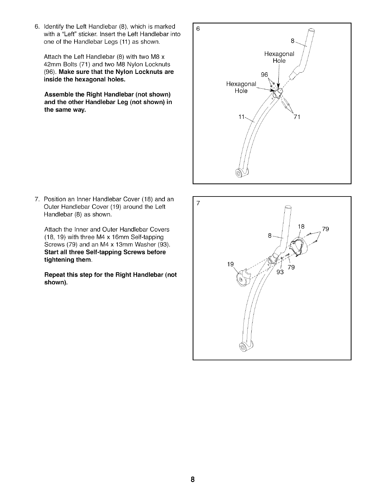
6. Identify the Left Handlebar (8), which is marked
with a "Left" sticker. Insert the Left Handlebar into
one of the Handlebar Legs (11) as shown.
Attach the Left Handlebar (8) with two M8 x
42mm Bolts (71) and two M8 Nylon Locknuts
(96). Make sure that the Nylon Locknuts are
inside the hexagonal holes.
Assemble the Right Handlebar (not shown)
and the other Handlebar Leg (not shown) in
the same way.
Hexagonal
Hole
Hexagonal
Hole f/!
96 _/
71
7. Position an Inner Handlebar Cover (18) and an
Outer Handlebar Cover (19) around the Left
Handlebar (8) as shown.
Attach the Inner and Outer Handlebar Covers
(18, 19) with three M4 x 16mm Self-tapping
Screws (79) and an M4 x 13mm Washer (93).
Start all three Self-tapping Screws before
tightening them.
Repeat this step for the Right Handlebar (not
shown),
19 79
93
18 79
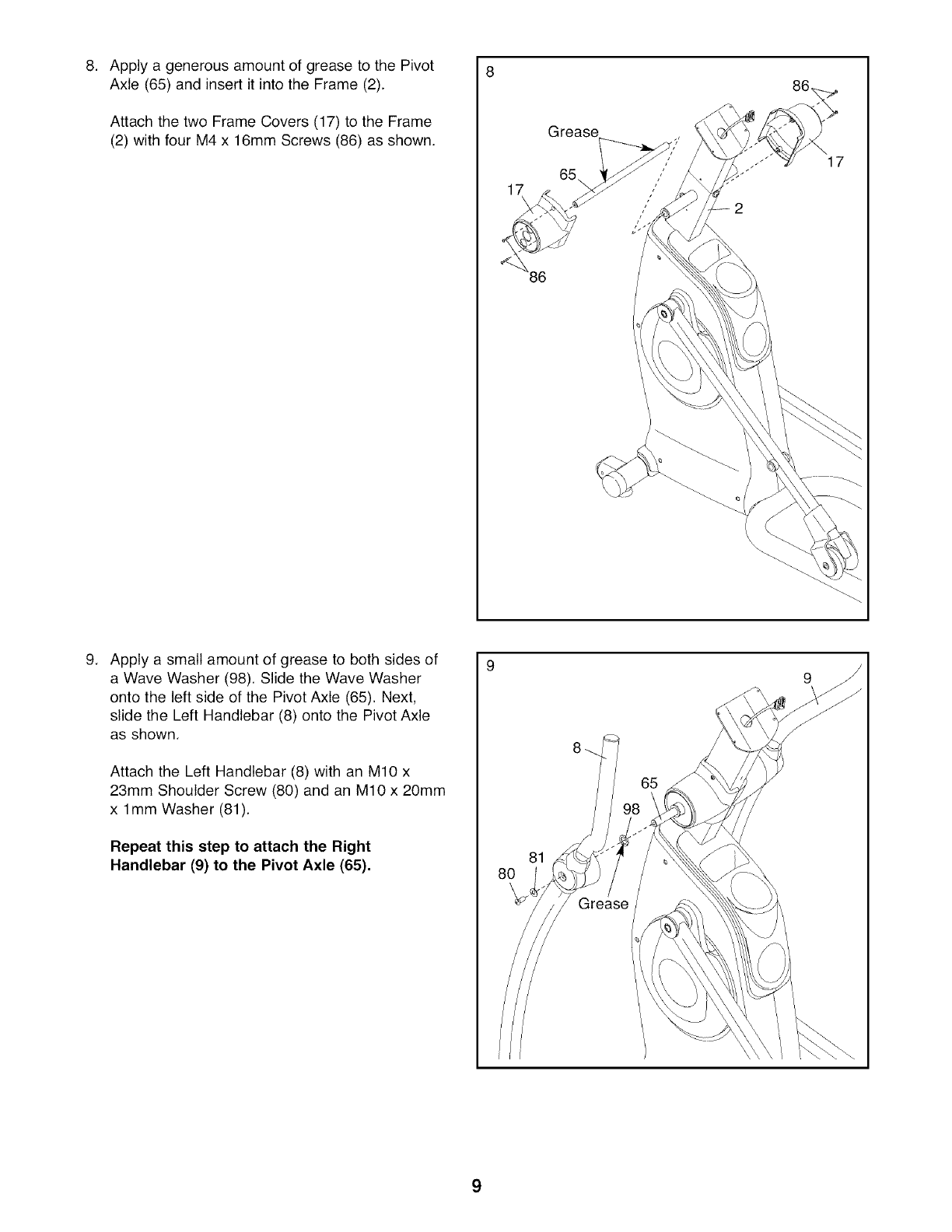
8. ApplyagenerousamountofgreasetothePivot 8
Axle(65)andinsertitintotheFrame(2).
AttachthetwoFrameCovers(17)totheFrame
(2)withfourM4x 16mmScrews(86)asshown.
17
9. Applya smallamountofgreaseto bothsidesof
aWaveWasher(98).SlidetheWaveWasher
ontotheleftsideofthePivotAxle(65).Next,
slidetheLeftHandlebar(8)ontothePivotAxle
asshown.
AttachtheLeftHandlebar(8)withanM10x
23mmShoulderScrew(80)andanM10x 20mm
x 1mmWasher(81).
Repeat this step to attach the Right
Handlebar (9) to the Pivot Axle (65), 81
9
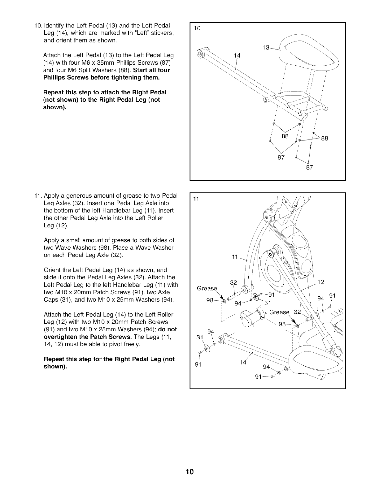
10. Identify the Left Pedal (13) and the Left Pedal
Leg (14), which are marked with "Left" stickers,
and orient them as shown.
Attach the Left Pedal (13) to the Left Pedal Leg
(14) with four M6 x 35mm Phillips Screws (87)
and four M6 Split Washers (88). Start all four
Phillips Screws before tightening them,
Repeat this step to attach the Right Pedal
(not shown) to the Right Pedal Leg (not
shown),
10
14
11. Apply a generous amount of grease to two Pedal
Leg Axles (32). Insert one Pedal Leg Axle into
the bottom of the left Handlebar Leg (11). Insert
the other Pedal Leg Axle into the Left Roller
Leg (12).
Apply a small amount of grease to both sides of
two Wave Washers (98). Place a Wave Washer
on each Pedal Leg Axle (32).
Orient the Left Pedal Leg (14) as shown, and
slide it onto the Pedal Leg Axles (32). Attach the
Left Pedal Leg to the left Handlebar Leg (11) with
two M10 x 20mm Patch Screws (91), two Axle
Caps (31), and two M10 x 25mm Washers (94).
Attach the Left Pedal Leg (14) to the Left Roller
Leg (12) with two M10 x 20mm Patch Screws
(91) and two M10 x 25mm Washers (94); do not
overtighten the Patch Screws, The Legs (11,
14, 12) must be able to pivot freely.
Repeat this step for the Right Pedal Leg (not
shown),
11
32
Grease \
94
91 14
91
Grease
12
10
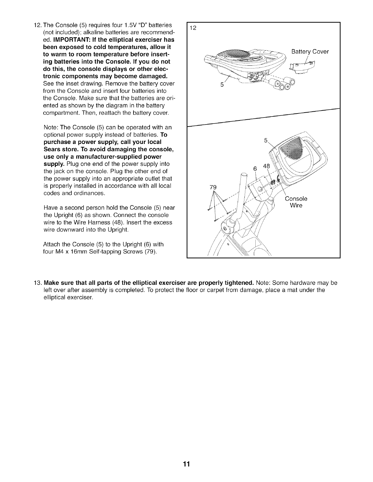
12. The Console (5) requires four 1.5V "D" batteries
(not included); alkaline batteries are recommend-
ed. IMPORTANT: If the elliptical exerciser has
been exposed to cold temperatures, allow it
to warm to room temperature before insert-
ing batteries into the Console. If you do not
do this, the console displays or other elec-
tronic components may become damaged.
See the inset drawing. Remove the battery cover
from the Console and insert four batteries into
the Console. Make sure that the batteries are ori-
ented as shown by the diagram in the battery
compartment. Then, reattach the battery cover.
Note: The Console (5) can be operated with an
optional power supply instead of batteries. To
purchase a power supply, call your local
Sears store. To avoid damaging the console,
use only a manufacturer-supplied power
supply. Plug one end of the power supply into
the jack on the console. Plug the other end of
the power supply into an appropriate outlet that
is properly installed in accordance with all local
codes and ordinances.
Have a second person hold the Console (5) near
the Upright (6) as shown. Connect the console
wire to the Wire Harness (48). Insert the excess
wire downward into the Upright.
Attach the Console (5) to the Upright (6) with
four M4 x 16mm Self-tapping Screws (79).
12
79
5\
Battery Cover
J
Console
Wire
13. Make sure that all parts of the elliptical exerciser are properly tightened. Note: Some hardware may be
left over after assembly is completed. To protect the floor or carpet from damage, place a mat under the
elliptical exerciser.
11
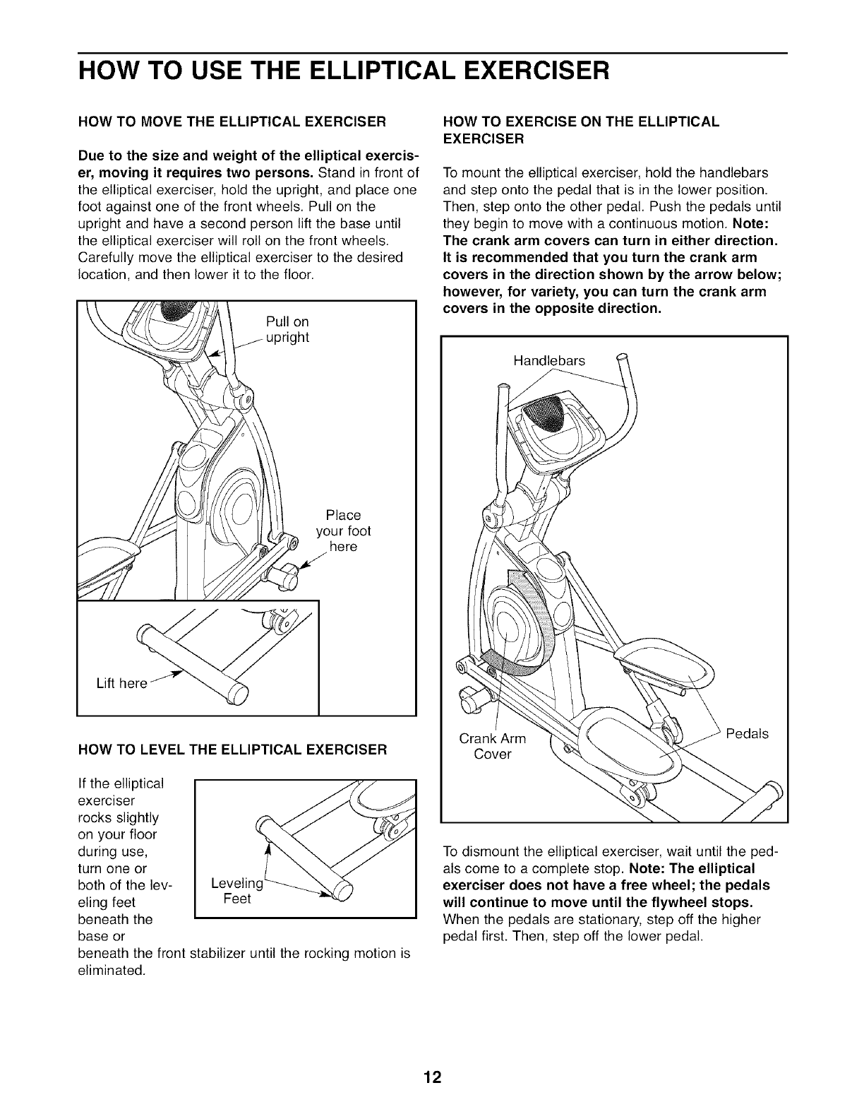
HOW TO USE THE ELLIPTICAL EXERCISER
HOW TO MOVE THE ELLIPTICAL EXERCISER
Due to the size and weight of the elliptical exercis-
er, moving it requires two persons. Stand in front of
the elliptical exerciser, hold the upright, and place one
foot against one of the front wheels. Pull on the
upright and have a second person lift the base until
the elliptical exerciser will roll on the front wheels.
Carefully move the elliptical exerciser to the desired
location, and then lower it to the floor.
Pull on
•ht
Place
your foot
here
Lift here
HOW TO LEVEL THE ELLIPTICAL EXERCISER
If the elliptical
exerciser
rocks slightly
on your floor
during use,
turn one or
both of the lev- Leveling
eling feet Feet
beneath the
base or
beneath the front stabilizer until the rocking motion is
eliminated.
HOW TO EXERCISE ON THE ELLIPTICAL
EXERCISER
To mount the elliptical exerciser, hold the handlebars
and step onto the pedal that is in the lower position.
Then, step onto the other pedal. Push the pedals until
they begin to move with a continuous motion. Note:
The crank arm covers can turn in either direction.
It is recommended that you turn the crank arm
covers in the direction shown by the arrow below;
however, for variety, you can turn the crank arm
covers in the opposite direction.
Handlebars
Crank Arm
Cover
Pedals
To dismount the elliptical exerciser, wait until the ped-
als come to a complete stop. Note: The elliptical
exerciser does not have a free wheel; the pedals
will continue to move until the flywheel stops,
When the pedals are stationary, step off the higher
pedal first. Then, step off the lower pedal.
12
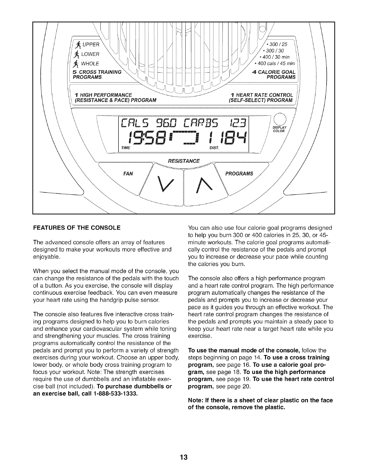
UPPER
,_ LOWER
j_ WHOLE
5 CROSS TRAINING
PROGRAMS
IHIGH PERFORMANCE
(RESISTANCE & PACE) PROGRAM
300 /25
•300 /30
• 400 / 30 min
• 400 cals / 45 min
4 CALORIE GOAL
PROGRAMS
HEART RATE CONTROL
(SELF-SELECT) PROGRAM J
TIME
RES_TANCE
FAN
123
PROGRAMS
FEATURES OF THE CONSOLE
The advanced console offers an array of features
designed to make your workouts more effective and
enjoyable.
When you select the manual mode of the console, you
can change the resistance of the pedals with the touch
of a button. As you exercise, the console will display
continuous exercise feedback. You can even measure
your heart rate using the handgrip pulse sensor.
The console also features five interactive cross train-
ing programs designed to help you to burn calories
and enhance your cardiovascular system while toning
and strengthening your muscles. The cross training
programs automatically control the resistance of the
pedals and prompt you to perform a variety of strength
exercises during your workout. Choose an upper body,
lower body, or whole body cross training program to
focus your workout. Note: The strength exercises
require the use of dumbbells and an inflatable exer-
cise ball (not included). To purchase dumbbells or
an exercise ball, call 1-888-533-1333.
You can also use four calorie goal programs designed
to help you burn 300 or 400 calories in 25, 30, or 45-
minute workouts. The calorie goal programs automati-
cally control the resistance of the pedals and prompt
you to increase or decrease your pace while counting
the calories you burn.
The console also offers a high performance program
and a heart rate control program. The high performance
program automatically changes the resistance of the
pedals and prompts you to increase or decrease your
pace as it guides you through an effective workout. The
heart rate control program changes the resistance of
the pedals and prompts you maintain a steady pace to
keep your heart rate near a target heart rate while you
exercise.
To use the manual mode of the console, follow the
steps beginning on page 14. To use a cross training
program, see page 16. To use a calorie goal pro-
gram, see page 18. To use the high performance
program, see page 19. To use the heart rate control
program, see page 20.
Note: If there is a sheet of clear plastic on the face
of the console, remove the plastic.
13
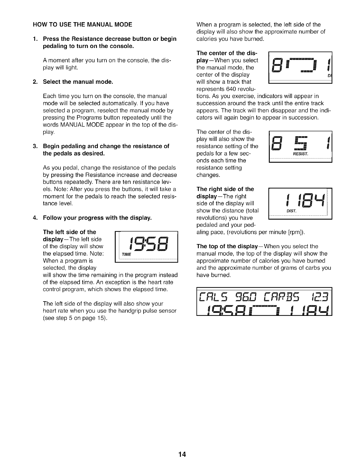
HOW TO USE THE MANUAL MODE
1. Press the Resistance decrease button or begin
pedaling to turn on the console,
A moment after you turn on the console, the dis-
play will light.
2. Select the manual mode,
Each time you turn on the console, the manual
mode will be selected automatically. If you have
selected a program, reselect the manual mode by
pressing the Programs button repeatedly until the
words MANUAL MODE appear in the top of the dis-
play.
3. Begin pedaling and change the resistance of
the pedals as desired.
As you pedal, change the resistance of the pedals
by pressing the Resistance increase and decrease
buttons repeatedly. There are ten resistance lev-
els. Note: After you press the buttons, it will take a
moment for the pedals to reach the selected resis-
tance level.
4. Follow your progress with the display.
The left side of the
display--The left side
of the display will show
the elapsed time. Note:
When a program is
selected, the display
will show the time remaining in the program instead
of the elapsed time. An exception is the heart rate
control program, which shows the elapsed time.
The left side of the display will also show your
heart rate when you use the handgrip pulse sensor
(see step 5 on page 15).
When a program is selected, the left side of the
display will also show the approximate number of
calories you have burned.
The center of the dis-
play--When you select
the manual mode, the
center of the display
will show a track that
represents 640 revolu-
".......!1
m
m m
=" I
mmm
tions. As you exercise, indicators will appear in
succession around the track until the entire track
appears. The track will then disappear and the indi-
cators will again begin to appear in succession.
The center of the dis-
play will also show the
resistance setting of the
pedals for a few sec-
onds each time the
resistance setting
changes.
The right side of the
display--The right
side of the display will
show the distance (total
revolutions) you have
pedaled and your ped-
QLJ
DIST.
aling pace, (revolutions per minute [rpm]).
The top of the display--When you select the
manual mode, the top of the display will show the
approximate number of calories you have burned
and the approximate number of grams of carbs you
have burned.
ERL5 9S.n ERPB5
F--"M !
14
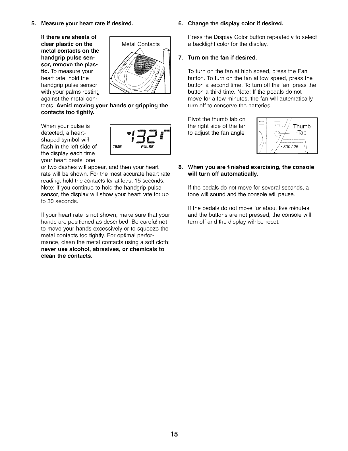
5. Measure your heart rate if desired.
If there are sheets of I
clear plastic on the I Metal Contacts
metal contacts on the
handgrip pulse sen-
sor, remove the plas-
tic, To measure your
heart rate, hold the
handgrip pulse sensor
with your palms resting
against the metal con-
tacts. Avoid moving your hands or gripping the
contacts too tightly.
When your pulse is
detected, a heart-
shaped symbol will
flash in the left side of
the display each time
your heart beats, one
TIME PULSE
or two dashes will appear, and then your heart
rate will be shown. For the most accurate heart rate
reading, hold the contacts for at least 15 seconds.
Note: If you continue to hold the handgrip pulse
sensor, the display will show your heart rate for up
to 30 seconds.
If your heart rate is not shown, make sure that your
hands are positioned as described. Be careful not
to move your hands excessively or to squeeze the
metal contacts too tightly. For optimal perfor-
mance, clean the metal contacts using a soft cloth;
never use alcohol, abrasives, or chemicals to
clean the contacts.
6. Change the display color if desired.
Press the Display Color button repeatedly to select
a backlight color for the display.
7. Turn on the fan if desired,
.
To turn on the fan at high speed, press the Fan
button. To turn on the fan at low speed, press the
button a second time. To turn off the fan, press the
button a third time. Note: If the pedals do not
move for a few minutes, the fan will automatically
turn off to conserve the batteries.
Pivot the thumb tab on
the right side of the fan
to adjust the fan angle.
....Thumb
I ! J'7 ............................
When you are finished exercising, the console
will turn off automatically.
If the pedals do not move for several seconds, a
tone will sound and the console will pause.
If the pedals do not move for about five minutes
and the buttons are not pressed, the console will
turn off and the display will be reset.
15
HOW TO USE A CROSS TRAINING PROGRAM
1. Press the Resistance decrease button or begin
pedaling to turn on the console,
A moment after you turn on the console, the dis-
play will light.
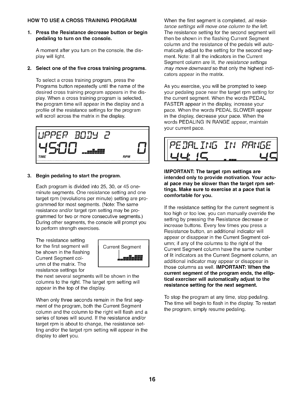
2. Select one of the five cross training programs.
To select a cross training program, press the
Programs button repeatedly until the name of the
desired cross training program appears in the dis-
play. When a cross training program is selected,
the program time will appear in the display and a
profile of the resistance settings for the program
will scroll across the matrix in the display.
UPPEP 9P_,,g
¢3
!-,7'U U =,==idB U
TiME RPM
3. Begin pedaling to start the program,
Each program is divided into 25, 30, or 45 one-
minute segments. One resistance setting and one
target rpm (revolutions per minute) setting are pro-
grammed for most segments. (Note: The same
resistance and/or target rpm setting may be pro-
grammed for two or more consecutive segments.)
During other segments, the console will prompt you
to perform strength exercises.
The resistance setting
for the first segment will
be shown in the flashing
Current Segment col-
umn of the matrix. The
resistance settings for
Current Segment
.mkBi
the next several segments will be shown in the
columns to the right. The target rpm setting will
appear in the top of the display.
When only three seconds remain in the first seg-
ment of the program, both the Current Segment
column and the column to the right will flash and a
series of tones will sound. If the resistance and/or
target rpm is about to change, the resistance set-
ting and/or the target rpm setting will appear in the
display to alert you.
When the first segment is completed, all resis-
tance settings will move one column to the left.
The resistance setting for the second segment will
then be shown in the flashing Current Segment
column and the resistance of the pedals will auto-
matically adjust to the setting for the second seg-
ment. Note: tf all the indicators in the Current
Segment column are lit, the resistance settings
may move downwardso that only the highest indi-
cators appear in the matrix.
As you exercise, you will be prompted to keep
your pedaling pace near the target rpm setting for
the current segment. When the words PEDAL
FASTER appear in the display, increase your
pace. When the words PEDAL SLOWER appear
in the display, decrease your pace. When the
words PEDALING IN RANGE appear, maintain
your current pace.
!-- l.=_iJf-mL =LI _L3 JLI_
m-! !q ....
IMPORTANT: The target rpm settings are
intended only to provide motivation, Your actu-
al pace may be slower than the target rpm set-
tings, Make sure to exercise at a pace that is
comfortable for you,
[f the resistance setting for the current segment is
too high or too low, you can manually override the
setting by pressing the Resistance decrease or
increase buttons. Every few times you press a
Resistance button, an additional indicator will
appear or disappear in the Current Segment col-
umn; if any of the columns to the right of the
Current Segment column have the same number
of lit indicators as the Current Segment column, an
additional indicator may appear or disappear in
those columns as well. IMPORTANT: When the
current segment of the program ends, the ellip-
tical exerciser will automatically adjust to the
resistance setting for the next segment,
To stop the program at any time, stop pedaling.
The time will begin to flash in the display. To restart
the program, simply resume pedaling.
16
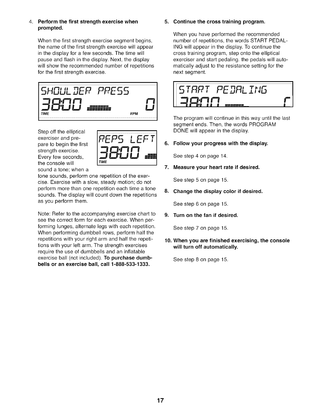
Perform the first strength exercise when
prompted,
When the first strength exercise segment begins,
the name of the first strength exercise will appear
in the display for a few seconds. The time will
pause and flash in the display. Next, the display
will show the recommended number of repetitions
for the first strength exercise.
t'tl tl
HuuL,gER PPES5
D'Lt Lt =U====qL== ILl
TIME RPM
Step off the elliptical
exerciser and pre-
pare to begin the first
strength exercise. _'_
Every few seconds,
the console will TIME
sound a tone; when a
tone sounds, perform one repetition of the exer-
cise. Exercise with a slow, steady motion; do not
perform more than one repetition each time a tone
sounds. The display will count down the repetitions
as you perform them.
5. Continue the cross training program.
When you have performed the recommended
number of repetitions, the words START PEDAL-
ING will appear in the display. To continue the
cross training program, step onto the elliptical
exerciser and start pedaling, the pedals will auto-
matically adjust to the resistance setting for the
next segment.
I
I
t ,t'l r'l F
I r--JmJ J J J _=_=_=_=_=_=_=__ I
The program will continue in this way until the last
segment ends. Then, the words PROGRAM
DONE will appear in the display.
6. Follow your progress with the display.
7.
.
Note: Refer to the accompanying exercise chart to 9.
see the correct form for each exercise. When per-
forming lunges, alternate legs with each repetition.
When performing dumbbell rows, perform half the
repetitions with your right arm and half the repeti- 10.
tions with your left arm. The strength exercises
require the use of dumbbells and an inflatable
exercise ball (not included). To purchase dumb-
bells or an exercise ball, call 1-888-533-1333.
See step 4 on page 14.
Measure your heart rate if desired.
See step 5 on page 15.
Change the display color if desired.
See step 6 on page 15.
Turn on the fan if desired.
See step 7 on page 15.
When you are finished exercising, the console
will turn off automatically.
See step 8 on page 15.
17
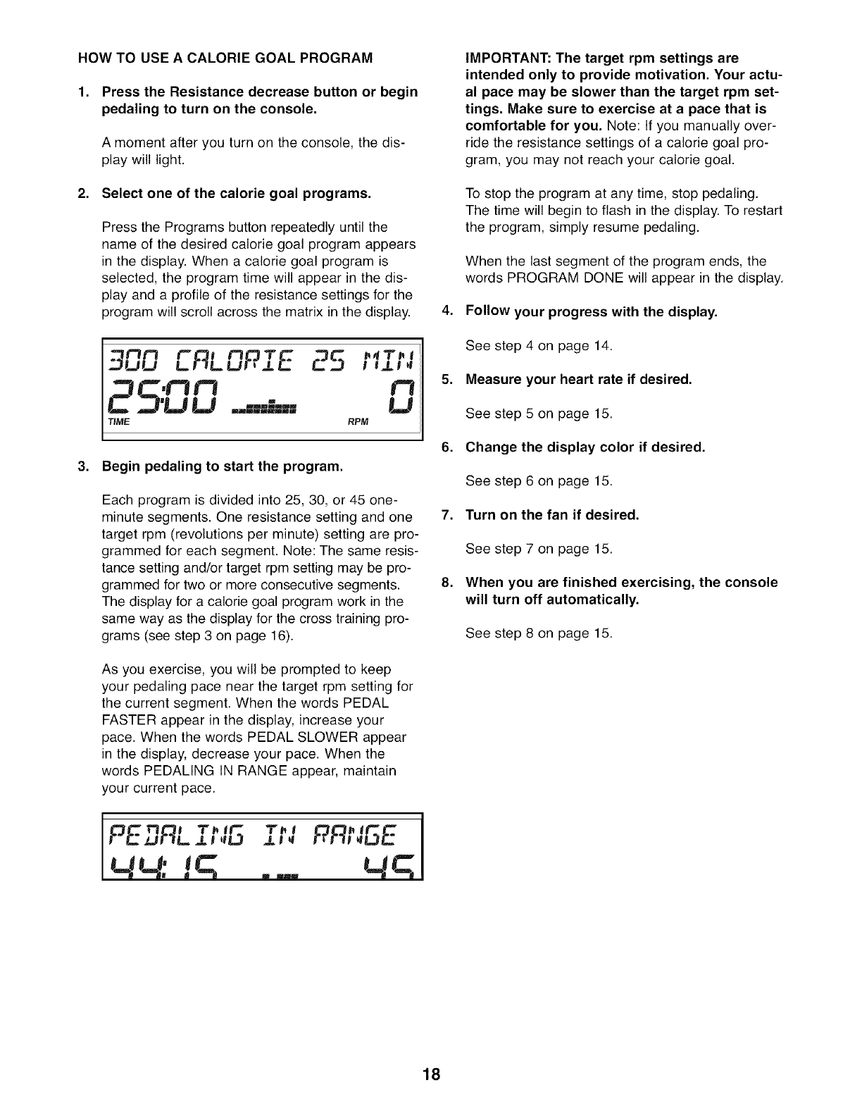
HOW TO USE A CALORIE GOAL PROGRAM
1. Press the Resistance decrease button or begin
pedaling to turn on the console,
A moment after you turn on the console, the dis-
play will light.
2. Select one of the calorie goal programs,
Press the Programs button repeatedly until the
name of the desired calorie goal program appears
in the display. When a calorie goat program is
selected, the program time will appear in the dis-
play and a profile of the resistance settings for the
program will scroll across the matrix in the display.
900 '-°' 25 .,,T.,
LF-_LUf_ J.E._ I eJL! _l
=.qr'LJLI ..=-.-.-=-.'.=-= LJ
TIME. RPM
3. Begin pedaling to start the program,
.
.
.
Each program is divided into 25, 30, or 45 one-
minute segments. One resistance setting and one 7.
target rpm (revolutions per minute) setting are pro-
grammed for each segment. Note: The same resis-
tance setting and/or target rpm setting may be pro-
grammed for two or more consecutive segments. 8.
The display for a calorie goat program work in the
same way as the display for the cross training pro-
grams (see step 3 on page 16).
As you exercise, you will be prompted to keep
your pedaling pace near the target rpm setting for
the current segment. When the words PEDAL
FASTER appear in the display, increase your
pace. When the words PEDAL SLOWER appear
in the display, decrease your pace. When the
words PEDALING IN RANGE appear, maintain
your current pace.
IMPORTANT: The target rpm settings are
intended only to provide motivation, Your actu-
al pace may be slower than the target rpm set-
tings, Make sure to exercise at a pace that is
comfortable for you, Note: tf you manually over-
ride the resistance settings of a calorie goal pro-
gram, you may not reach your calorie goal.
To stop the program at any time, stop pedaling.
The time will begin to flash in the display. To restart
the program, simply resume pedaling.
When the last segment of the program ends, the
words PROGRAM DONE wilt appear in the display.
Follow your progress with the display.
See step 4 on page 14.
Measure your heart rate if desired.
See step 5 on page 15.
Change the display color if desired.
See step 6 on page 15.
Turn on the fan if desired.
See step 7 on page 15.
When you are finished exercising, the console
will turn off automatically.
See step 8 on page 15.
18
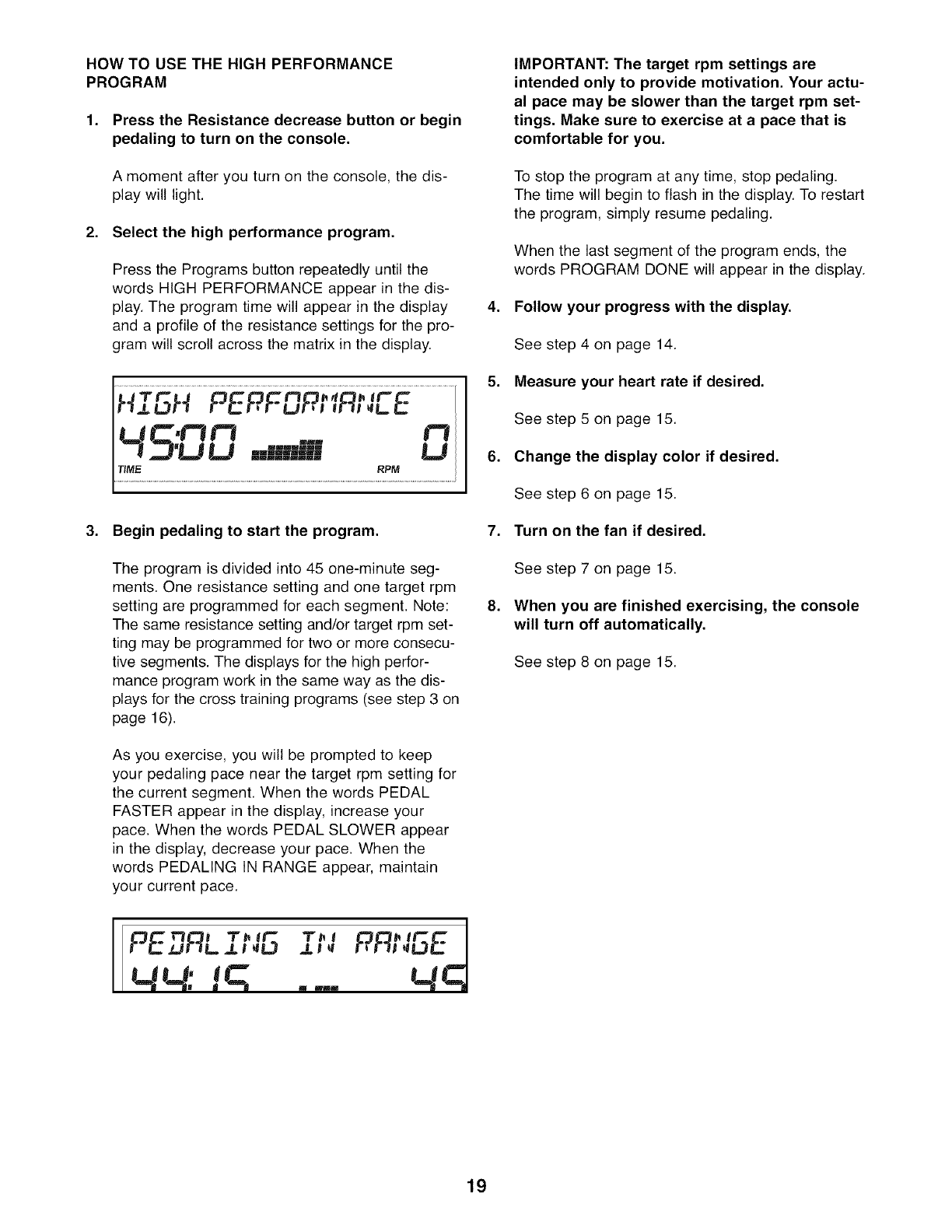
HOW TO USE THE HIGH PERFORMANCE
PROGRAM
1. Press the Resistance decrease button or begin
pedaling to turn on the console.
A moment after you turn on the console, the dis-
play will light.
2. Select the high performance program,
Press the Programs button repeatedly until the
words HIGH PERFORMANCE appear in the dis-
play. The program time will appear in the display
and a profile of the resistance settings for the pro-
gram will scroll across the matrix in the display.
Hj. H PEPFuP, ,R,,uE
S:DD D
3. Begin pedaling to start the program,
The program is divided into 45 one-minute seg-
ments. One resistance setting and one target rpm
setting are programmed for each segment. Note:
The same resistance setting and/or target rpm set-
ting may be programmed for two or more consecu-
tive segments. The displays for the high perfor-
mance program work in the same way as the dis-
plays for the cross training programs (see step 3 on
page 16).
As you exercise, you will be prompted to keep
your pedaling pace near the target rpm setting for
the current segment. When the words PEDAL
FASTER appear in the display, increase your
pace. When the words PEDAL SLOWER appear
in the display, decrease your pace. When the
words PEDALING IN RANGE appear, maintain
your current pace.
I _ l T_ IJ"S_ T_ l
PEARL J_! eLJ J_l
MM:" !q u mu_
IMPORTANT: The target rpm settings are
intended only to provide motivation, Your actu-
al pace may be slower than the target rpm set-
tings, Make sure to exercise at a pace that is
comfortable for you,
To stop the program at any time, stop pedaling.
The time will begin to flash in the display. To restart
the program, simply resume pedaling.
When the last segment of the program ends, the
words PROGRAM DONE will appear in the display.
4. Follow your progress with the display.
See step 4 on page 14.
5. Measure your heart rate if desired.
See step 5 on page 15.
6. Change the display color if desired.
See step 6 on page 15.
7. Turn on the fan if desired.
See step 7 on page 15.
8. When you are finished exercising, the console
will turn off automatically.
See step 8 on page 15.
19
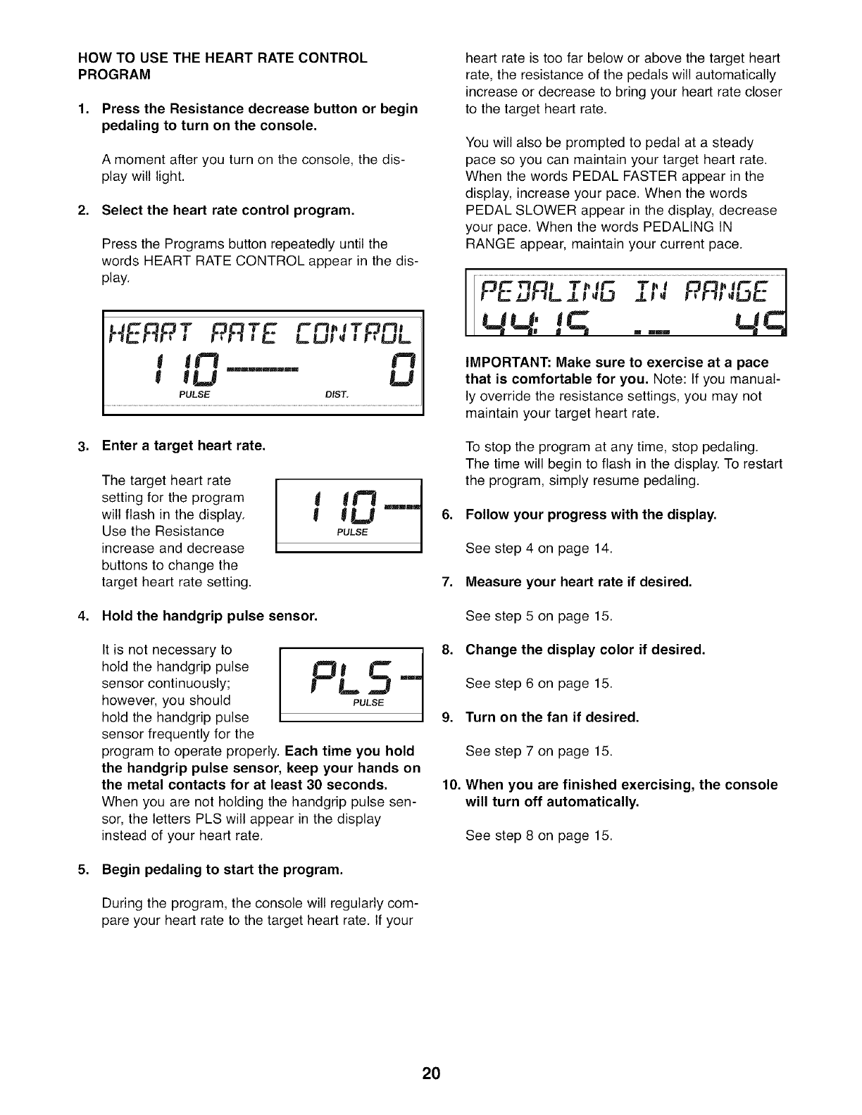
HOW TO USE THE HEART RATE CONTROL
PROGRAM
1. Press the Resistance decrease button or begin
pedaling to turn on the console.
A moment after you turn on the console, the dis-
play will light.
2. Select the heart rate control program.
Press the Programs button repeatedly until the
words HEART RATE CONTROL appear in the dis-
play.
HERPT f:?RTE rm.,-r m,
L,U! _ i r[LJL=
I lI_ I"t
! tU ......... U
PULSE DIST,
3. Enter a target heart rate.
The target heart rate
setting for the program
will flash in the display.
Use the Resistance
increase and decrease
buttons to change the
target heart rate setting.
I IU ....
PULSE
4. Hold the handgrip pulse sensor.
(t is not necessary to
hold the handgrip pulse
sensor continuously;
however, you should
hold the handgrip pulse
sensor frequently for the
program to operate properly. Each time you hold
the handgrip pulse sensor, keep your hands on
the metal contacts for at least 30 seconds,
When you are not holding the handgrip pulse sen-
sor, the letters PLS will appear in the display
instead of your heart rate.
5. Begin pedaling to start the program.
During the program, the console will regularly com-
pare your heart rate to the target heart rate. If your
heart rate is too far below or above the target heart
rate, the resistance of the pedals will automatically
increase or decrease to bring your heart rate closer
to the target heart rate.
You will also be prompted to pedal at a steady
pace so you can maintain your target heart rate.
When the words PEDAL FASTER appear in the
display, increase your pace. When the words
PEDAL SLOWER appear in the display, decrease
your pace. When the words PEDALING tN
RANGE appear, maintain your current pace.
r_............... ]
r-_r.Z J=Jt-lL.=Lt _L3 J,l _ f_f!l (LJ(_...T.m
( (( (' (JL--'I
i_ _ _ _ _ _ _
IMPORTANT: Make sure to exercise at a pace
that is comfortable for you, Note: If you manual-
ly override the resistance settings, you may not
maintain your target heart rate.
To stop the program at any time, stop pedaling.
The time will begin to flash in the display. To restart
the program, simply resume pedaling.
6. Follow your progress with the display.
See step 4 on page 14.
7. Measure your heart rate if desired.
See step 5 on page 15.
8. Change the display color if desired.
See step 6 on page 15.
9. Turn on the fan if desired.
10.
See step 7 on page 15.
When you are finished exercising, the console
will turn off automatically.
See step 8 on page 15.
20
MAINTENANCE AND TROUBLESHOOTING
Inspect and tighten all parts of the elliptical exerciser
regularly. Replace any worn parts immediately.
To clean the elliptical exerciser, use a damp cloth and
a small amount of mild soap. IMPORTANT: To avoid
damage to the console, keep liquids away from
the console and keep the console out of direct
sunlight.
CONSOLE TROUBLESHOOTING
If the console display becomes dim, the batteries
should be replaced; most console problems are the
result of low batteries. See assembly step 12 on page
11 for replacement instructions.
HANDGRIP PULSE SENSOR TROUBLESHOOTING
If the console does not display your heart rate when
you hold the handgrip pulse sensor, or if the displayed
heart rate appears to be too high or too low, see step
5 on page 15.
HOW TO LEVEL THE ELLIPTICAL EXERCISER
If the elliptical exerciser rocks slightly on your floor
during use, see HOW TO LEVEL THE ELLIPTICAL
EXERCISER on page 12.
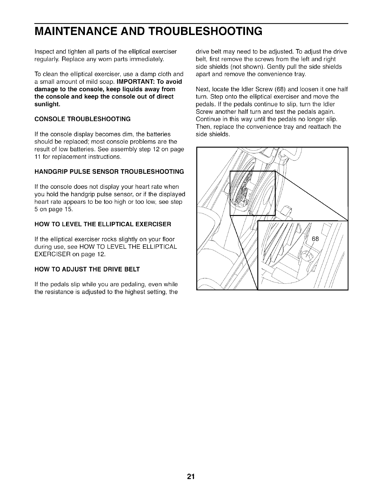
HOW TO ADJUST THE DRIVE BELT
If the pedals slip while you are pedaling, even while
the resistance is adjusted to the highest setting, the
drive belt may need to be adjusted. To adjust the drive
belt, first remove the screws from the left and right
side shields (not shown). Gently pull the side shields
apart and remove the convenience tray.
Next, locate the Idler Screw (68) and loosen it one half
turn. Step onto the elliptical exerciser and move the
pedals. If the pedals continue to slip, turn the Idler
Screw another half turn and test the pedals again.
Continue in this way until the pedals no longer slip.
Then, replace the convenience tray and reattach the
side shields.
21
EXERCISE GUIDELINES
These guidelines will help you to plan your exercise
program. For detailed exercise information, obtain a
reputable book or consult your physician. Remember,
proper nutrition and adequate rest are essential for
successful results.
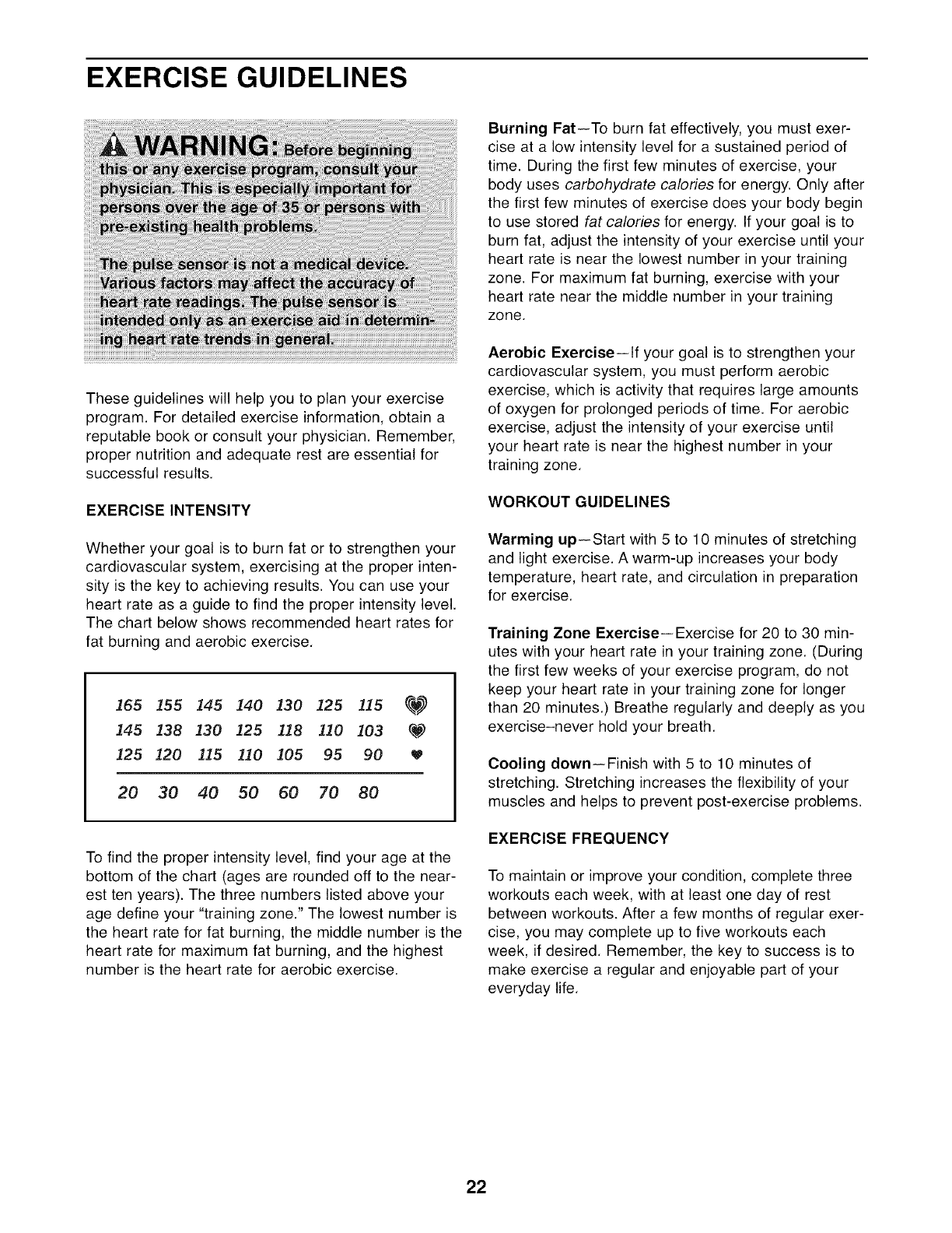
EXERCISE INTENSITY
Whether your goal is to burn fat or to strengthen your
cardiovascular system, exercising at the proper inten-
sity is the key to achieving results. You can use your
heart rate as a guide to find the proper intensity level.
The chart below shows recommended heart rates for
fat burning and aerobic exercise.
165 155 145 140 130 125 115 _
145 138 130 125 118 110 103 _
125 120 115 110 105 95 90
20 30 40 50 60 70 80
To find the proper intensity level, find your age at the
bottom of the chart (ages are rounded off to the near-
est ten years). The three numbers listed above your
age define your "training zone." The lowest number is
the heart rate for fat burning, the middle number is the
heart rate for maximum fat burning, and the highest
number is the heart rate for aerobic exercise.
Burning Fat--To burn fat effectively, you must exer-
cise at a low intensity level for a sustained period of
time. During the first few minutes of exercise, your
body uses carbohydrate calories for energy. Only after
the first few minutes of exercise does your body begin
to use stored fat calories for energy, tf your goal is to
burn fat, adjust the intensity of your exercise until your
heart rate is near the lowest number in your training
zone. For maximum fat burning, exercise with your
heart rate near the middle number in your training
zone.
Aerobic Exercise--lf your goal is to strengthen your
cardiovascular system, you must perform aerobic
exercise, which is activity that requires large amounts
of oxygen for prolonged periods of time. For aerobic
exercise, adjust the intensity of your exercise until
your heart rate is near the highest number in your
training zone.
WORKOUT GUIDELINES
Warming up--Start with 5 to 10 minutes of stretching
and light exercise. A warm-up increases your body
temperature, heart rate, and circulation in preparation
for exercise.
Training Zone Exercise--Exercise for 20 to 30 min-
utes with your heart rate in your training zone. (During
the first few weeks of your exercise program, do not
keep your heart rate in your training zone for longer
than 20 minutes.) Breathe regularly and deeply as you
exercise-never hold your breath.
Cooling down--Finish with 5 to 10 minutes of
stretching. Stretching increases the flexibility of your
muscles and helps to prevent post-exercise problems.
EXERClSE FREQUENCY
To maintain or improve your condition, complete three
workouts each week, with at least one day of rest
between workouts. After a few months of regular exer-
cise, you may complete up to five workouts each
week, if desired. Remember, the key to success is to
make exercise a regular and enjoyable part of your
everyday life.
22
STRENGTH TRAINING GUIDELINES
During strength exercises, you must maintain proper
form for the best results. Maintaining proper form
involves moving through the full range of motion for
each exercise and moving only the appropriate parts
of the body. Exercising in an uncontrolled manner will
reduce the benefits of strength exercises. On the exer-
cise chart accompanying this manual are photographs
showing the correct form for several strength exercis-
es.
Perform each repetition of each strength exercise
smoothly and without pausing. The exertion phase of
each repetition should last only about half as long as
the return phase. Proper breathing is also important.
Exhale during the exertion phase of each repetition
and inhale during the return phase--never hold your
breath.
To increase the size and strength of your muscles, you
must work your muscles at a level close to their maxi-
mum capacity. Your muscles will adapt and grow as
you progressively increase the amount of weight that
you use. You can tone your muscles by working them
at a moderate percentage of their capacity. The proper
amount of weight to use for each strength exercise
depends on you--you must gauge your limits and
select an appropriate amount of weight.
It is important to avoid overdoing it during the first few
months of your exercise program. Progress at your
own pace and be sensitive to your body's signals. If
you experience pain or dizziness at any time while
exercising, stop immediately and cool down. Find out
what is wrong before continuing. Remember that ade-
quate rest and a proper diet are important factors in
any exercise program.
23
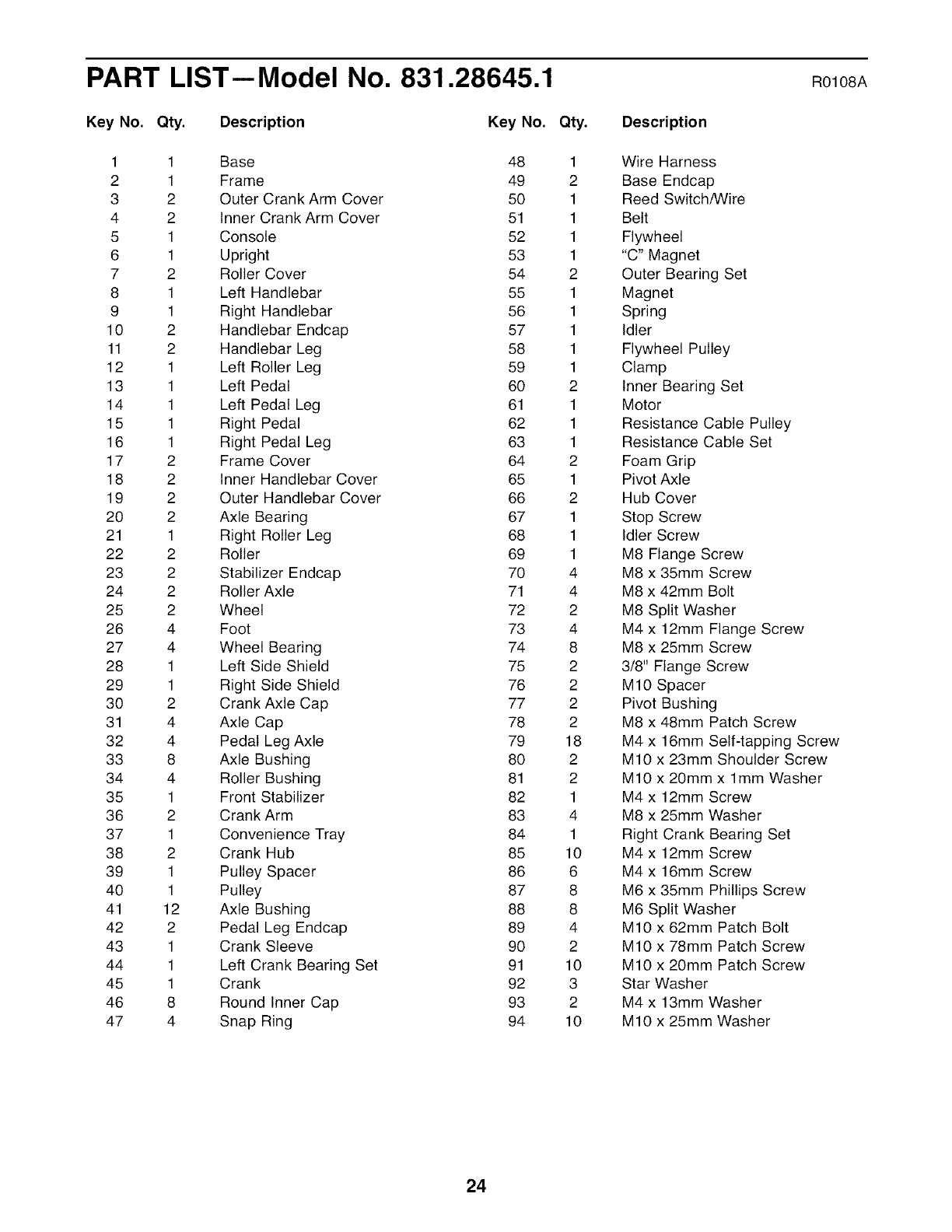
PART LIST--Model No. 831.28645.1 Rolo8A
Key No. Qty. Description Key No.
1 1 Base 48
2 1 Frame 49
3 2 Outer Crank Arm Cover 50
4 2 Inner Crank Arm Cover 51
5 1 Console 52
6 1 Upright 53
7 2 Roller Cover 54
8 1 Left Handlebar 55
9 1 Right Handlebar 56
10 2 Handlebar Endcap 57
11 2 Handlebar Leg 58
12 1 Left Roller Leg 59
13 1 Left Pedal 60
14 1 Left Pedal Leg 61
15 1 Right Pedal 62
16 1 Right Pedal Leg 63
17 2 Frame Cover 64
18 2 Inner Handlebar Cover 65
19 2 Outer Handlebar Cover 66
20 2 Axle Bearing 67
21 1 Right Roller Leg 68
22 2 Roller 69
23 2 Stabilizer Endcap 70
24 2 Roller Axle 71
25 2 Wheel 72
26 4 Foot 73
27 4 Wheel Bearing 74
28 1 Left Side Shield 75
29 1 Right Side Shield 76
30 2 Crank Axle Cap 77
31 4 Axle Cap 78
32 4 Pedal Leg Axle 79
33 8 Axle Bushing 80
34 4 Roller Bushing 81
35 1 Front Stabilizer 82
36 2 Crank Arm 83
37 1 Convenience Tray 84
38 2 Crank Hub 85
39 1 Pulley Spacer 86
40 1 Pulley 87
41 12 Axle Bushing 88
42 2 Pedal Leg Endcap 89
43 1 Crank Sleeve 90
44 1 Left Crank Bearing Set 91
45 1 Crank 92
46 8 Round Inner Cap 93
47 4 Snap Ring 94
Qty.
1
2
1
1
1
1
2
1
1
1
1
1
2
1
1
1
2
1
2
1
1
1
4
4
2
4
8
2
2
2
2
18
2
2
1
4
1
10
6
8
8
4
2
10
3
2
10
Description
Wire Harness
Base Endcap
Reed Switch/Wire
Belt
Flywheel
"C" Magnet
Outer Bearing Set
Magnet
Spring
Idler
Flywheel Pulley
Clamp
Inner Bearing Set
Motor
Resistance Cable Pulley
Resistance Cable Set
Foam Grip
Pivot Axle
Hub Cover
Stop Screw
Idler Screw
M8 Flange Screw
M8 x 35mm Screw
M8 x 42mm Bolt
M8 Split Washer
M4 x 12mm Flange Screw
M8 x 25mm Screw
3/8" Flange Screw
M10 Spacer
Pivot Bushing
M8 x 48mm Patch Screw
M4 x 16mm Self-tapping Screw
M10 x 23mm Shoulder Screw
M10 x 20mm x lmm Washer
M4 x 12mm Screw
M8 x 25mm Washer
Right Crank Bearing Set
M4 x 12mm Screw
M4 x 16mm Screw
M6 x 35mm Phillips Screw
M6 Split Washer
M10 x 62mm Patch Bolt
M10 x 78mm Patch Screw
M10 x 20mm Patch Screw
Star Washer
M4 x 13mm Washer
M10 x 25mm Washer
24

Key No. Qty. Description Key No. Qty. Description
95 7 M8 x 16mm Patch Screw * - Hex Key
96 6 M8 Nylon Locknut * - Grease
97 2 M10 Nylon Locknut * - User's Manual
98 8 Wave Washer
Note: Specifications are subject to change without notice. See the back cover of this manual for information
about ordering replacement parts. *These parts are not illustrated. If a part is missing, call 1-888-533-1333.
25
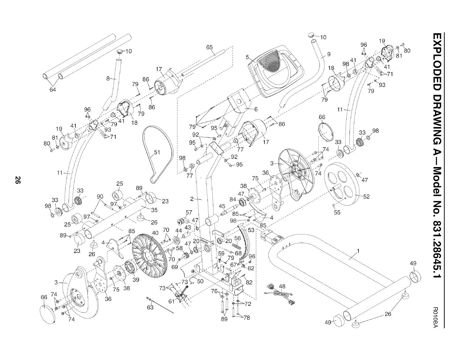
64
19 41
,
8O
/33
33
98
23
66 7;
93
90
26 r
36
//
/
25
86
79
86
79
17
18
39
'5 38
89
65
92
95
5\
66
17 33
74
89 78
96 19
98
81
I'll
X
I'--
0
I'1"1
Q
I
e_,.
49 4_
c,
o
co
3>
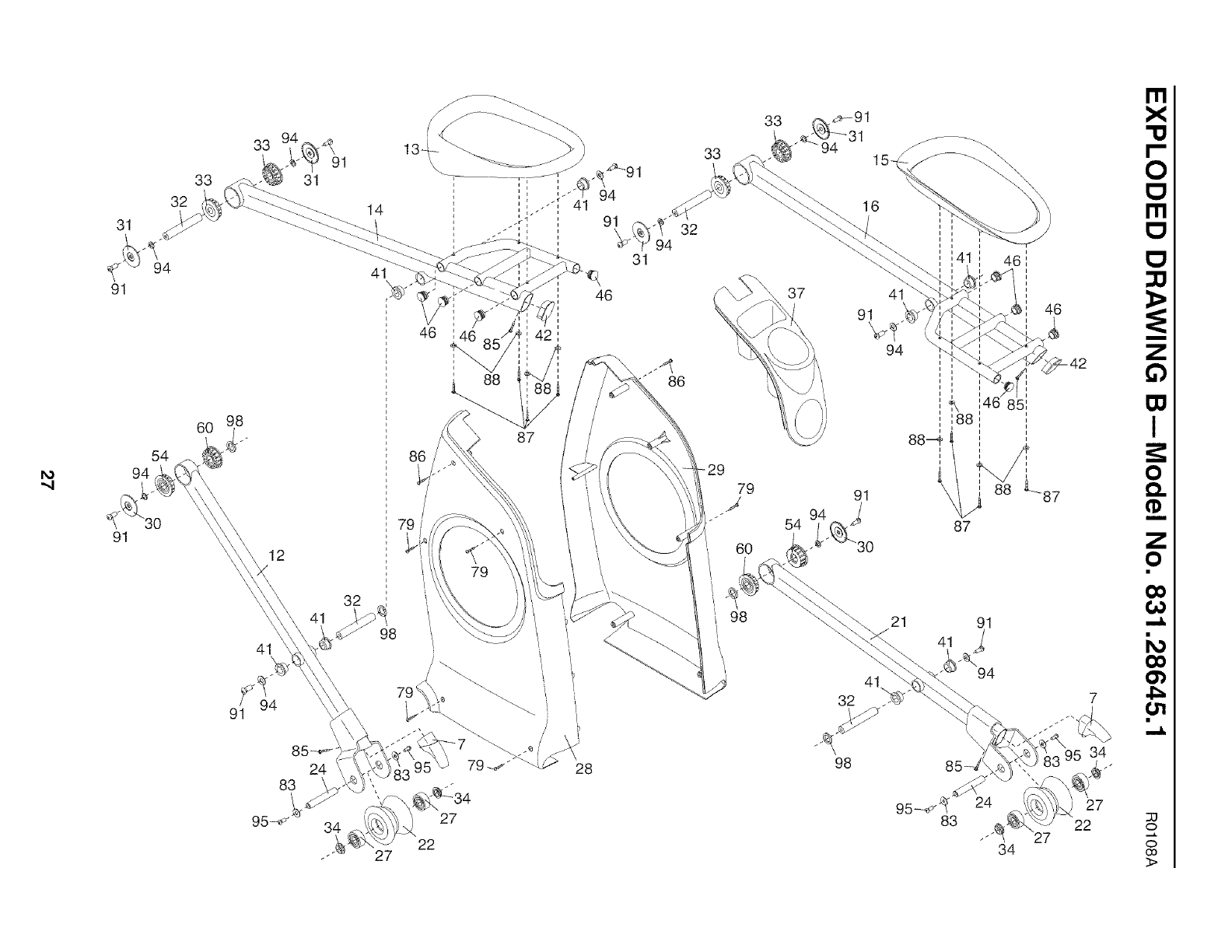
""4
31
91
91
32
54
94
33
91
33
31
12
32
41
94
14
41
98
27
137
46 42
87
79
_LL_34
27
22
28
31
46
33
86
-29
79
6O
98
33
37
54
41
91
94
46
91 88 L--87
41
32
98 34
27
22
I'll
X
I'--
0
Ill
63
I
e_.
z
4_
t,,rl
33
o
c,
co
3>

iiiiiiiiiiiiiiii{
iiiiiiiiiiiiiiii'
iiiiiiiiiiiiiiii
iiiiiiiiiiiiiiii
iiiiiiiiiiiiiiii
iiiiiiiiiiiiiiii
iiiiiiiiiiiiiiii
iiiiiiiiiiiiiiii
iiiiiiiiiiiiiiii
iiiiiiiiiiiiiiii
iiiiiiiiiiiiiiii
iiiiiiiiiiiiiiii
iiiiiiiiiiiiiiii
iiiiiiiiiiiiiiii
iiiiiiiiiiiiiiii
iiiiiiiiiiiiiiii
iiiiiiiiiiiiiiii
iiiiiiiiiiiiiiii
iiiiiiiiiiiiiiii
iiiiiiiiiiiiiiii
iiiiiiiiiiiiiiii
iiiiiiiiiiiiiiii
iiiiiiiiiiiiiiii
iiiiiiiiiiiiiiii
iiiiiiiiiiiiiiii
iiiiiiiiiiiiiiii
uuuuuuu_
Your Home
For repair--in your home--of all major brand appliances, lawn and garden equipment,
or heating and cooling systems, no matter who made it, no matter who sold it!
For the replacement parts, accessories, and user's manuals that you need to do-it-yourself.
For Sears professional installation of home appliances
and items like garage door openers and water heaters.
1-800-4-MY-HOME ® (1-800-469-4663)
Call anytime, day or night (U.S.A. and Canada)
www.sears.com www.sears.ca
Our Home
For repair of carry-in items like vacuums, lawn equipment,
and electronics, call or go on-line for the location of your nearest
Sears Parts & Repair Center.
1-800-488-1222 Call anytime, day or night (U.S.A. only)
www.sears.com
To purchase a protection agreement (U.S.A.)
or maintenance agreement (Canada) on a product serviced by Sears:
1-800-827-6655 (U.S.A.) 1-800-361-6665 (Canada)
® Registered Trademark /TMTrademark /SMService Mark of Sears Brands, LLC
@Marca Registrada /TMMarca de Fabrica /SMMarca de Servicio de Sears Brands. LLC
f
90 DAY FULL WARRANTY
f
If this Sears Elliptical Exerciser fails due to a defect in material or workmanship within 90 days of the
date of purchase, call 1-800-4-MY-HOME ®(1-800-469-4663) to arrange for free repair (or replacement
if repair proves impossible). The frame is warranted for 10 years.
This warranty does not apply when the Elliptical Exerciser is used commercially or for rental purposes.
This warranty gives you specific legal rights, and you may also have other rights which vary from state
to state.
Sears, Roebuck and Co,, Hoffman Estates, IL 60179
J
J
Part No. 262873 R0108A Printed in China © 2008 ICON IP, Inc.
