Proform 831293030 User Manual 320X Manuals And Guides L0212230
PROFORM Treadmill Manual L0212230 PROFORM Treadmill Owner's Manual, PROFORM Treadmill installation guides
User Manual: Proform 831293030 831293030 PROFORM PROFORM 320X - Manuals and Guides View the owners manual for your PROFORM PROFORM 320X #831293030. Home:Fitness Equipment Parts:Proform Parts:Proform PROFORM 320X Manual
Open the PDF directly: View PDF ![]() .
.
Page Count: 19
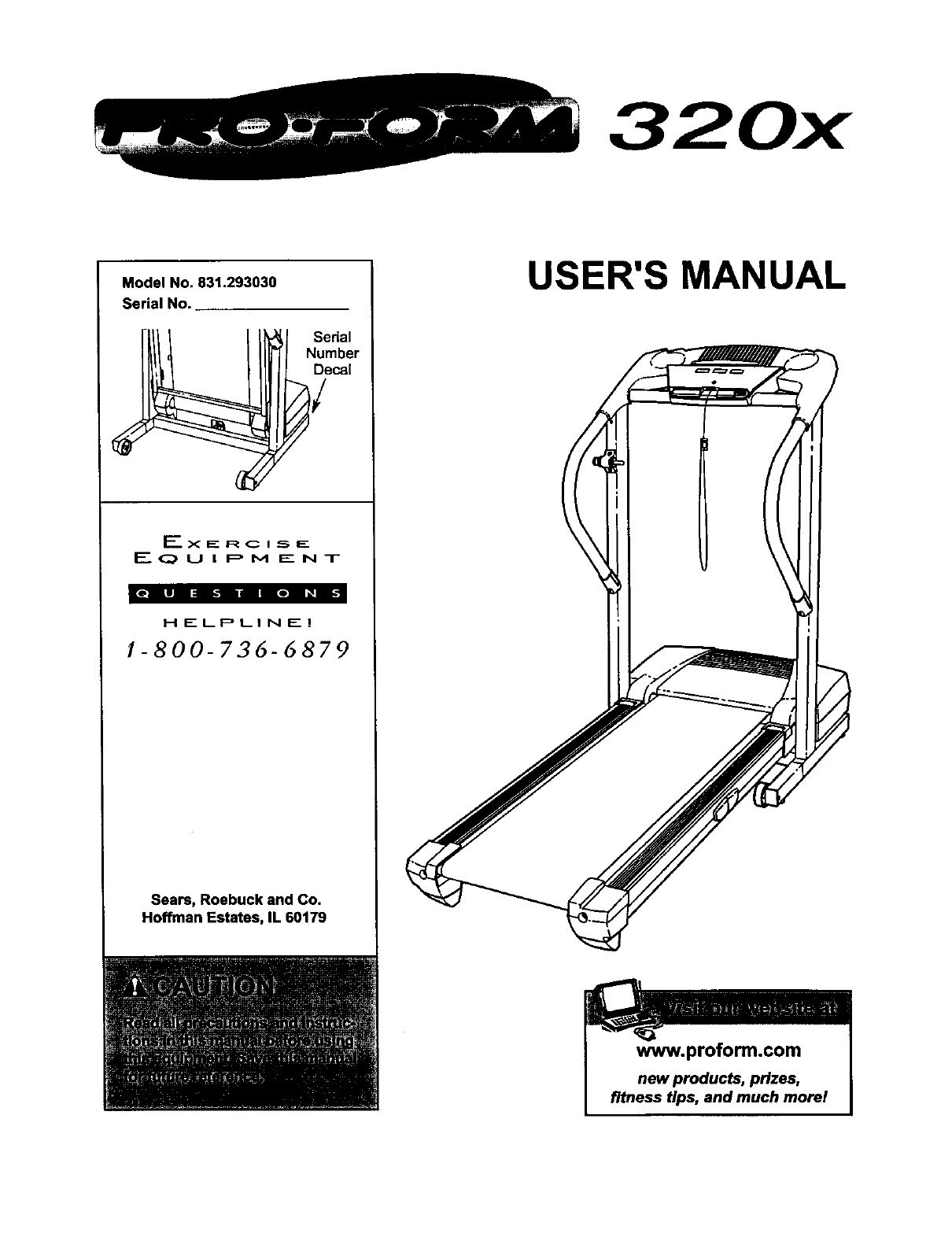
Model No. 831.293030
Serial No.
Ex IE_ R C I _5 E
EQUIPMENT
|e|li _t ire| _
HELPLINE!
!-800-736-6879
Seam, Roebuck and Co.
Hoffman Estates, IL 60179
USER'S MANUAL
www.proform.com
newproducts, prizes,
fitness tips, and much morel

TABLE OF CONTENTS
IMPORTANT PRECAUTIONS ................................................................ 2
BEFORE YOU BEGIN ...................................................................... 4
ASSEMBLY ............................................................................... 5
OPERATION AND ADJUSTMENT ............................................................. 8
HOW TO FOLD AND MOVE THE TREADMILL .................................................. 11
TROUBLESHOOTING ..................................................................... 13
CONDITIONING GUIDELINES ............................................................... 15
ORDERING REPLACEMENT PARTS .................................................. Back Cover
FULL 90 DAY WARRANTY ........................................................... Back Cover
Note: An EXPLODED DRAWING and a PART LIST are attached in the center of this manual.
IMPORTANT PRECAUTIONS
2

The decals shown have been placed on your treadmill. If a decal is missing, or if
it is not legible, please call our ton-free HELPLINE to order a free replacement
decal (see the front cover of this manual). Apply the decal in the location
shown. Note: The decals are not shown at actual size.
I
3

BEFORE YOU BEGIN
Thank you for selectingthe revolutionary PROFORM ®
320x treadmill. The 320x treadmill combinesadvanced
technologywith innovativedesignto help you get the
most fromyour exerciseprogram in the convenience
and privacyof your home. And when you'renot exer-
cising,the unique320x treadmillcan be foldedup, re-
quidnglossthan half the floor spaceof other treadmills.
For your benefit, read this manual carefully before
using the treadmill. If you have additionalquestions,
please call our toll-freeHELPLINE at 1-800-736-6879,
MondaythroughSaturday, 7 a.m. until7 p.m. Central
Time (excludingholidays).To help us assist you,
please note the productmodel numberand serial num-
ber before calling. The model numberof the treadmill
is 831.293030. The sedal number can be foundon a
decal attached to the treadmill(see the front cover of
thismanual for the location).
Before readingfurther, please reviewthe drawing
below and familiadze yourselfwith the labeled parts.
Water BottleHolder
(Bottle notincluded)
Storage Latch /_
Handrail
Bookreck
Console
Key/Clip
Updght
CircuitBreaker
Walking Belt-
Foot \
RIGHT SIDE
BACK
CushionedWalking Platform
for maximumexercisecomfort
Rear
Adjustment Bolts
4
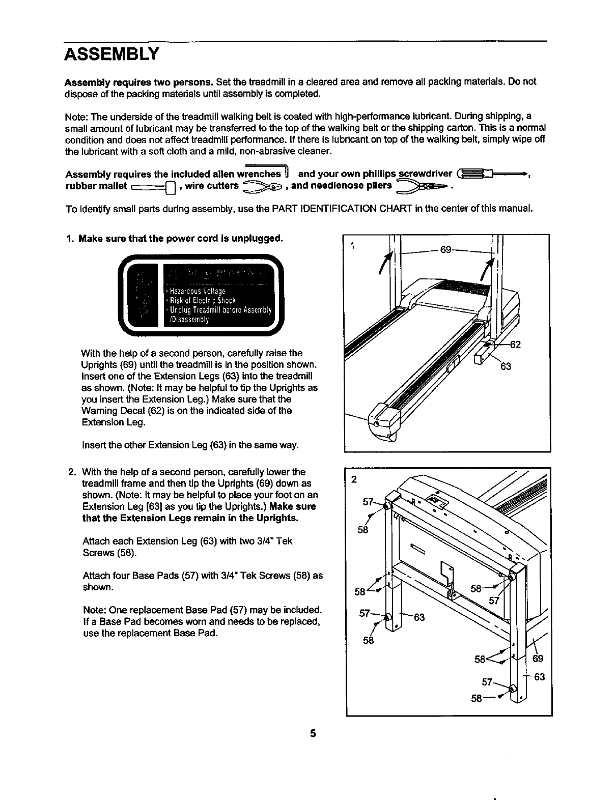
ASSEMBLY
Assembly requires two persons. Set the treadmillin a cleared area and remove all packingmaterials.Do not
disposeof the packingmatedalsuntilassemblyis completed.
Note:The undersideof the treadmillwalking belt is coated with high-performance lubricant. During shipping,a
small amount of lubricant may be transferred to the top of the walking belt or the shippingcarton. This is anormal
condition and does not affect treadmill performance. If there is lubricant on top of the walking belt, simply wipe off
the lubricant with a soft cloth and a mild, non-abrasive cleaner.
Assembly requires the included allen wrsnc==_es and your own phillips screwdriver (__,
rubber mallet _,wire cutters _,and nsedlenose pliers _BS_, •
To identify small parts during assembly, use the PART IDENTIFICATION CHART in the center of this manual.
1. Make sure that the power cord is unplugged.
With the help of asecond person, carefully raisethe
Updghts (69) untilthe treadmill is inthe position shown.
Insert one of the ExtensionLegs (63) into the treadmill
as shown. (Note: It may be helpfulto tip the Uprightsas
you insert the ExtensionLeg.) Make sure that the
Warning Decal (62) is on the indicated sideof the
ExtensionLeg.
Insert the otherExtensionLeg (63) inthe same way.
63
2. With the help of a second person,carefully lower the
treadmillframe and then tipthe Updghts(69) down as
shown. (Note: It may be helpfulto place your footon an
ExtensionLeg [63] as you tipthe Uprights.)Make sure
that the Extension Legs remain in the Uprights.
Attach each Extension Leg (63) with two 3/4" Tek
Screws (58).
Attachfour Base Pads (57) with 3/4"Tek Screws (58) as
shown.
Note:One replacement Base Pad (57) may be included.
If a Base Pad becomesworn and needs to be replaced,
use the replacement Base Pad.
2
57--
j_.."
58
I
57_
e_
/
58
5
3. With the help of asecond person, raise the Uprights(69)
to the vertical Position.Attach the Storage Latch (36) to
the left Uprightwithtwo 3/4" Screws(2). Remove the
LockKnob (30) from the Lock Pin (35). Make sure that
the LockPin Collar (33) and the Spring (32) are on the
Lock Pin as shown. Insertthe Lock Pin intothe Storage
Latch and tightenthe Lock Knob back onto the Lock Pin.
3
4. Identifythe RightHandrail (72), which has a large hole in
the left side. Feed the Wire Harness (42) up into the
bracketon the Right Handrail and out of the large hole in
the left side. (Note: It may be helpfulto use needlenose
pliersto pullthe Wire Hamess outof the large hole.)
Press a Handrail Cap (76) onto the lower end of the
Right Handrail as shown.
Insert the bracket on the RightHandrail (72) into the top
of the right Upright(69) so the HandrailCap (76) is rest-
ing against the Upright.Attachthe Right Handrailand the
Handrail Cap withthree 1" Bolts (37) and two Washers
(38) as shown. Firmly tighten the indicated Bolt but
do not tighten the other Bolt yet.
Attach the Left Handrail(not shown) as described above.
Note: There is not a wire harness onthe left side.
Large
Hole
38
-76
5. Attach the end of the groundwire to the smallhole in the
side of the Right Handrail (72) with a Silver Ground
Screw (75). Ground
Wire
75
6
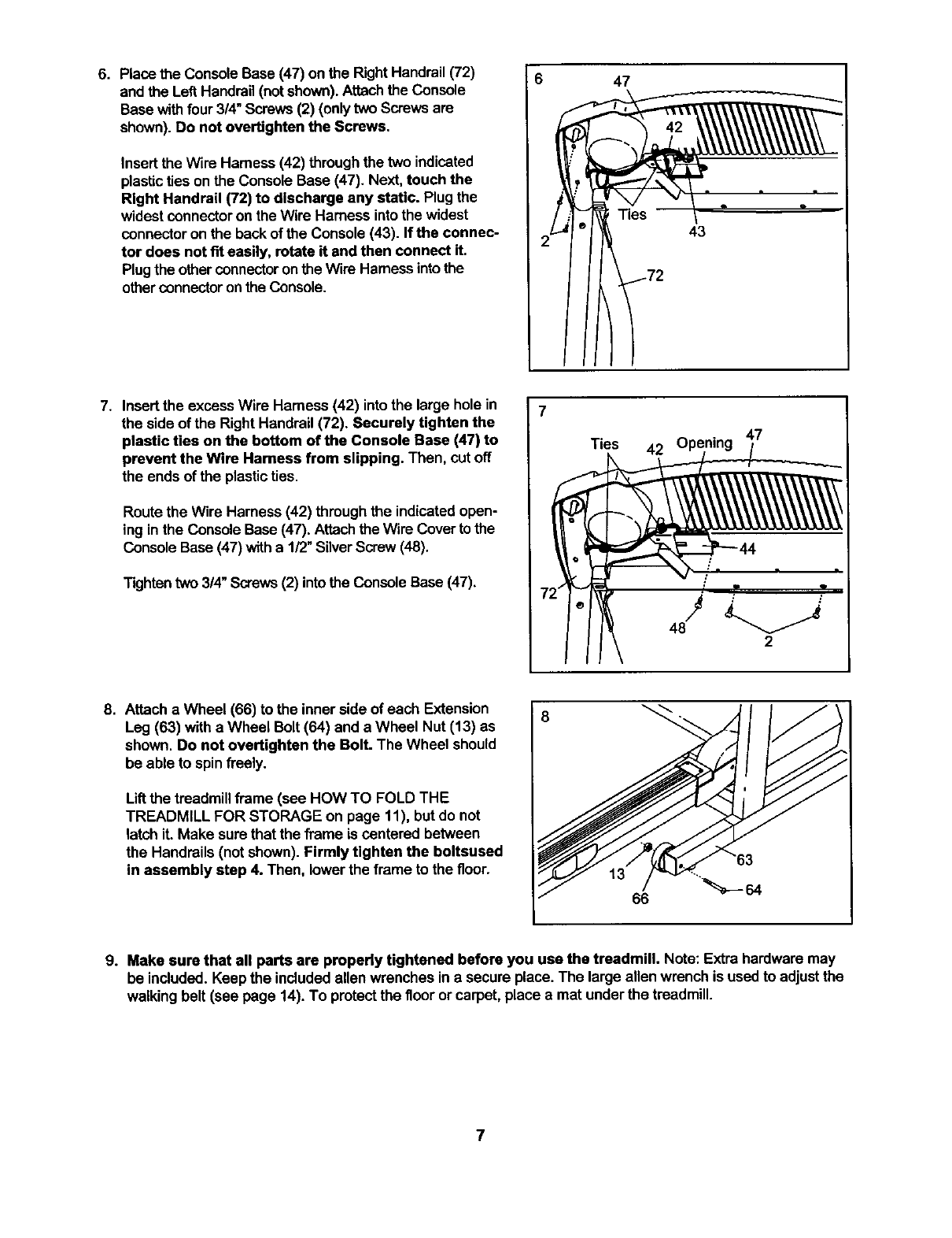
6. Place the Console Base (47) on the RightHandrail(72)
and the Left Handrail(not shown).Attachthe Console
Base withfour 314"Screws (2) (onlytwo Screws are
shown).Do not overtighten the Screws.
Insertthe Wire Harness (42) through the two indicated
plasticties onthe Console Base (47). Next, touch the
Right Handrail (72) to discharge any static. Plug the
widest connectoron the Wire Harness intothe widest
connector on the back of the Console (43). If the connec-
tor does not fit easily, rotate it and then connect it.
Plugthe otherconnector onthe Wire Harnessintothe
otherconnector onthe Console.
647
43
I
7. Insert the excess Wire Harness (42) intothe large hole in
the side of the Right Handrail(72). Securely tighten the
plastic ties on the bottom of the Console Base (47) to
prevent the Wire Harness from slipping. Then, cut off
the ends of the plasticties.
Route the Wire Harness (42) through the indicatedopen-
ing in the Console Base (47). Attachthe Wire Cover to the
Console Base (47) witha 1/2" SilverScrew (48).
Tighten two 3/4"Screws (2) into the Console Base (47).
7Ties 42 O_
Ill\ "
8. Attach a Wheel (66) to the inner side of each Extension
Leg (63) witha Wheel Bolt(64) and a Wheel Nut (13) as
shown. Do not overtighten the Bolt. The Wheel should
be able to spinfreely.
Liftthe treadmill frame (see HOW TO FOLD THE
TREADMILL FOR STORAGE on page 11), but do not
latchit. Make sure that the frame is centered between
the Handrails(not shown). Firmly tighten the boltsused
in assembly step 4. Then, lower the frame to the floor.
66
9. Make sure that all parts are property tightened before you use the treadmill. Note: Extra hardware may
be included. Keepthe includedallen wrenches in a secure place. The large allen wrench is usedto adjustthe
walking belt (see page 14). To protectthe floor or carpet, place a mat underthe treadmill.
OPERATION AND ADJUSTMENT
THE PERFORMANT LUBE TM WALKING BELT
Your treadmill features a walking belt coated with
PERFORMANT LUBETM, ahigh-performance lubdcent.
IMPORTANT: Never apply silicone spray or other
substances to the walking belt or the walking plat-
form. Such substances will deteriorate the walking
belt and cause excessive wear.
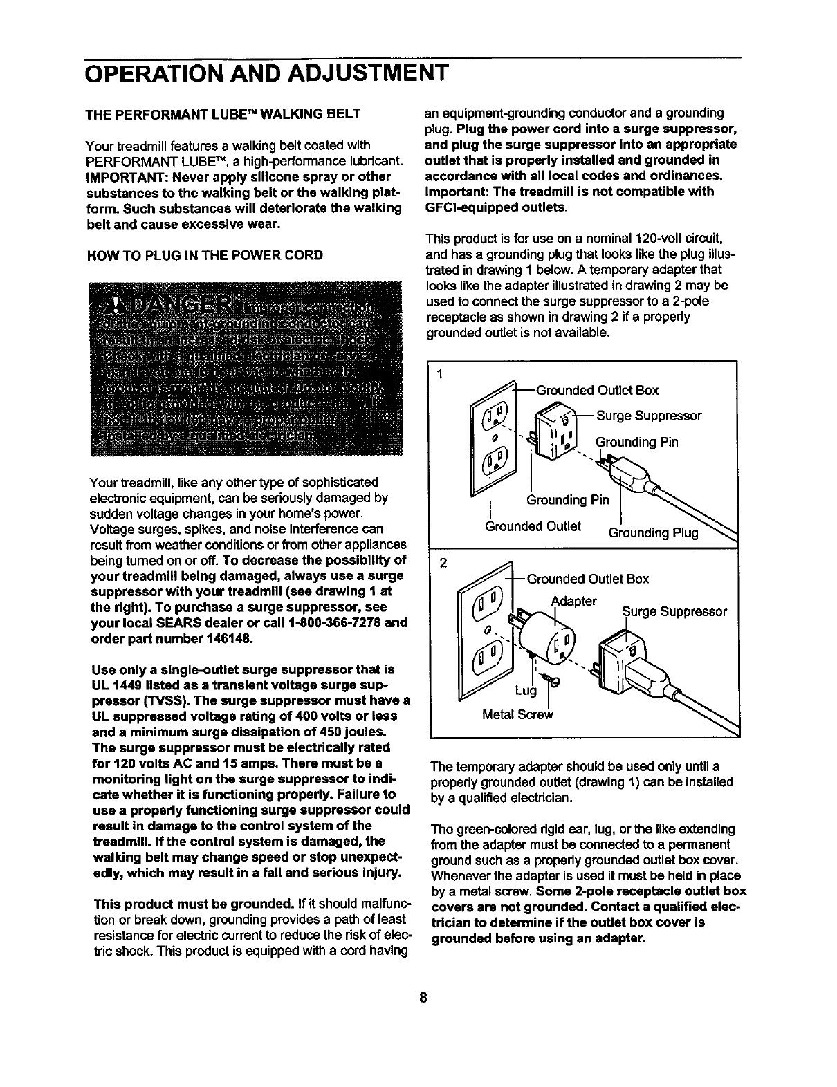
HOW TO PLUG IN THE POWER CORD
an equipment-groundingconductorand a grounding
plug. Plug the power cord into a surge suppressor,
and plug the surge suppressor Into an appropriate
outlet that is properly installed and grounded in
accordance with all local codes and ordinances.
Important: The treadmill is not compatible with
GFCl-equipped outlets.
This productis for use on a nominal 120-volt circuit,
and has a groundingplugthat looks likethe plugillus-
trated in drawing 1 below.A temporary adapter that
lookslikethe adapter illustratedindrawing 2 may be
usedto connectthe surge suppressorto a 2-pole
receptacleas shown in drawing2 if a propedy
groundedoutlet is not available.
Your treadmill,like any other type of sophisticated
electronic equipment,can be sedouslydamaged by
sudden voltage changes in your home's power.
Voltage surges, spikes, and noise interferencecan
resultfromweather conditionsor from other appliances
beingturned on or off. To decrease the possibility of
your treadmill being damaged, always use a surge
suppressor with your treadmill (see drawing t at
the dght). To purchase a surge suppressor, see
your local SEARS dealer or call 1-800-366-7278 and
order part number 146148.
Usa only a single-outlet surge suppressor that is
UL 1449 listed as a transient voltage surge sup-
pressor (TVSS). The surge suppressor must have a
UL suppressed voltage rating of 400 volts or less
and a minimum surge dissipation of 450 joules.
The surge suppressor must be electrically rated
for 120 volta AC and t5 amps. There must be a
monitoring light on the surge suppressor to indi-
cate whether it is functioning propedy. Failure to
use a properly functioning surge suppressor could
result in damage to the control system of the
treadmill. If the control system is damaged, the
walking belt may change speed or stop unexpect-
edly, which may result in a fall and serious injury.
This product must be grounded. If it should malfunc-
tion or break down, groundingprovidesa path of least
resistancefor electric currentto reduce the dsk of elec-
tric shock. This productis equippedwitha cord having
_Grounded OutletBox
_? l_:::gu:dSi:: pPr::sor
iunding
GroundedOutlet GroundingPlug_
Groundod Outlet Box
Adapter ^
["J JLk'_,--_l Surge _uppressor
Metal Screw
The temporaryadapter should be used only untila
propedygroundedoutlet (drawing 1) can be installed
by a qualifiedelectrician.
The green-coloreddgidear, lug, orthe like extending
from the adapter mustbe connectedto a permanent
groundsuchas a properlygroundedoutlet boxcover.
Whenever the adapter is used it must be held in place
by a metal screw. Some 2-pole receptacle outlet box
covers are not grounded. Contact a qualified elec-
trician to determine if the outlet box cover is
grounded before using an adapter.
8
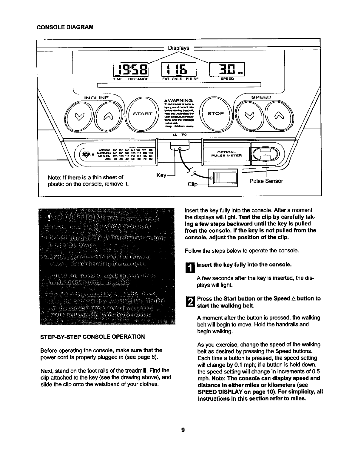
CONSOLE DIAGRAM
Displays
IJ9:SB 3.0.
I
Note: If there is a thin sheet of Key-- _-7-' I--
plastic on the console,removeit. Pulse Sensor
STEP-BY-STEP CONSOLE OPERATION
Before operatingthe console, make sure that the
power cord is propedypluggedin (see page 8).
Next, standon the footrailsof the treadmill.Findthe
clipattached to the key (see the drawing above), and
slidethe clip ontothe waistbandof your clothes.
Insert the keyfully into the console.After a moment,
the displayswill light.Test the clip by carefully tak-
Ing a few steps backward until the key Is pulled
from the console. If the key is not pulled from the
console, adjust the position of the clip.
Followthe steps below to operate the console.
_! Insert the key fully into the console.
A few seconds after the key is inserted, the dis-
playswill light.
B Press the Start button orthe Speed L_button to
start the walking belt.
A momentafter the buttonis pressed,the walking
beltwill beginto move.Hold the handrailsand
begin walking.
As you exercise, change the speed of the walking
belt as desiredby pressingthe Speed buttons.
Each time abuttonis pressed, the speed setting
will change by 0.1 mph; if a buttonis held down,
the speed settingwill change in incrementsof 0.5
mph. Note: The console can display speed and
distance in either miles or kilometers (see
SPEED DISPLAY on page 10). For simplicity, all
instructions in this section refer to miles.
9
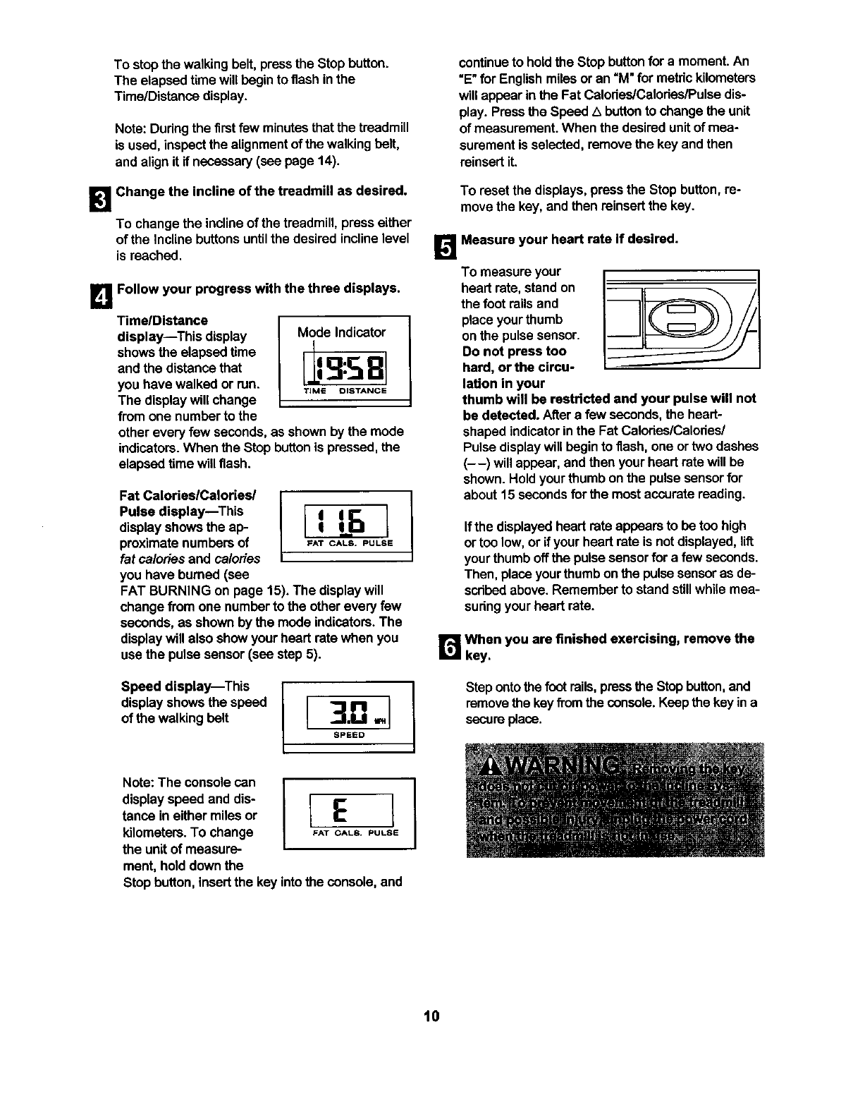
To stopthe walkingbelt, press the Stopbutton.
The elapsed time will begin to flashin the
Time/Distance display.
Note: Duringthe first few minutesthat the treadmill
is used, inspectthe alignmentof the walkingbelt,
and alignit if necessary(see page 14).
B Change the incline of the treadmill as desired.
To change the inclineof the treadmill, presseither
of the Inclinebuttonsuntilthe desired inclinelevel
is reached.
B Follow your progress with the three displays.
TimelDistance
display--This display
showsthe elapsed time
and the distance that
you have walked or run.
The displaywill change
from one numberto the
Mode Indicator
TIME DISTANCE
other every few seconds,as shown by the mode
indicators.When the Stop button is pressed, the
elapsed time will flash.
Fat CalorieslCalories/
Pulse display--This
displayshows the ap-
proximate numbersof
fat caloriesand calories
you have bumed (see
FAT BURNING on page 15). The displaywill
change from one numberto the other every few
seconds, as shown by the mode indicators.The
displaywill also showyour heart rate when you
use the pulse sensor (see step 5).
Speed display--This
displayshowsthe speed
of the walkingbelt
continue to hold the Stop button for amoment. An
"E"for Englishmilesor an "M"for metrickilometers
willappear in the Fat Calories/Calories/Pulsedis-
play. Press the Speed Abuttonto change the unit
of measurement.When the desiredunitof mea-
surement is selected, remove the key andthen
reinsertit.
To reset the displays,press the Stop button, re-
move the key, and then reinsert the key.
!_','_Measure your heart rate if desired.
To measure your
heart rate,stand on
the foot railsand
place yourthumb
on the pulsesensor.
Do not press too
hard, or the circu-
lation in your
thumb will be restricted and your pulse will not
be detected. After a few seconds,the heart-
shaped indicatorinthe Fat Calories/Calories/
Pulse displaywill beginto flash, one or two dashes
(--) will appear, and then your heart rate will be
shown. Holdyourthumb on the pulsesenser for
about 15 secondsforthe most accurate reading.
If the displayedheartrate appears to be too high
ortoo low, or if your heart rate is notdisplayed, lift
yourthumb offthe pulse sensorfor a few seconds.
Then, placeyourthumb on the pulsesensoras de-
scribedabove. Remember to standstillwhile mea-
suringyour heart rate.
r_When you are finished exercising, remove the
key.
Step onto the foot rails, press the Stop button, and
remove the key from the console. Keep the key in a
sect.Ira place.
Note:The consolecan
displayspeed and dis-
tance ineither milesor
kilometers.To change
the unit of measure-
ment, hold down the
[E ]
FAT OALS* PULSE
Stop button, insertthe key intothe console, and
I
10

HOW TO FOLD AND MOVE THE TREADMILL
HOW TO FOLD THE TREADMILL FOR STORAGE
Before folding the treadmill, unplugthe power cord. CAUTION:
You must be able to safely lift 45 pounds (20 kg) in order to
raise, lower, or move the treadmill.
1. Hold the treadmill withyour hands in the locations shown at
the right.To decrease the possibility of injury, bend your
legs and keep your back straight. As you raise the treed-
mill, make sure to lift with your legs rather than your
back. Raise the treadmill abouthalfway tothe vertical posi-
tion.
2. Move your right hand to the positionshown and holdthe
treadmill firmly.Using your left hand, pull the latch knob to
the left and hold it. Raise the treadmill until the latch pin is
aligned with the square hole between the frame and the foot
rail. Slowly release the latch knob and insert the latch pin into
the hole. Make sure that the frame is securely held by the
latch pin.
To protect the floor or carpet from damage, place a mat
under the treadmill. Keep the treadmill out of direct sun-
light. Do not leave the treadmill in the storage position in
temperatures above 85° Fahrenheit.
Engaged
HOW TO MOVE THE TREADMILL
Before movingthe treadmill,convert the treadmill to the storage
positionas descdbed above. Make sure that the frame is se-
curely held by the latch pin.
1. Hold the upper ends ofthe handrails.Place one footon the
base as shown.
2. Tilt the treadmill back untilit rollsfreely on the front wheels.
Carefully move the treadmill to the desired location.To re-
duce the risk of injury, use extreme caution while mov-
ing the treadmill. Do not move the treadmill over an un-
even surface.
3. Place one foot on the base, and carefullylower the treadmill
untilit is restinginthe storage position.
•Base
FrontWheels
11

HOW TO LOWER THE TREADMILL FOR USE
1. Hold the upper end ofthe treadmillwith yourrighthand as
shown. Usingyour left hand, pullthe latchknob to the left
and holdit. Pivotthe treadmilldown untilthe frame is past
the latch pin. Slowly release the latch knob.
Engaged
2. Hold the treadmill firmlywithboth hands, and lower the tread-
millto the floor. Do not drop the treadmill frame to the
floor. To decrease the possibility of injury, bend your
legs and keep your back straight.
12
TROUBLESHOOTING
Most treadmill problems can be solved by following the simple steps below. Find the symptom that
applies, and follow the steps listed. If further assistance is needed, call our toll-free HELPLINE at
1-800-736-6879, Monday through Saturday, 7 a.m. until 7 p.m. Central Time (excluding holidays).
PROBLEM: The power does not tum on
SOLUTION: a. Make sure that the power cord is plugged into a surge suppressor,and that the surge suppressor
is pluggedinto a propedygroundedoutlet (see page 8). Use only a single-outletsurge suppressor
that meets all of the specificationsdescribedon page 8. Important:The treadmillis not compatible
with GFCI-equipped outlets.
b. Afterthe power cord has been pluggedin, make surethat the key is fully insertedintothe console.
c. Check the circuitbreaker located onthe treadmill
frame near the power cord. If the switchprotrudes
as shown,the circuitbreaker has tripped.To reset
the circuitbreaker, wait for five minutes and then
pressthe switchback in. Tripped
Reset[_
PROBLEM: The power turns offduring use
SOLUTION: a. Check the circuitbreaker located onthe treadmill frame near the power cord (see the drawing
above). If the circuitbreaker has tripped,wait for fiveminutesand then pressthe switchback in.
b. Make sure that the power cord is plugged in. If the power cord is plugged in, unplug it, wait for
five minutes,and then plugit back in.
c. Remove the key from the console. Reinsertthe key fully intothe console.
d. If the treadmillstillwill notrun, please call our toll-freeHELPLINE.
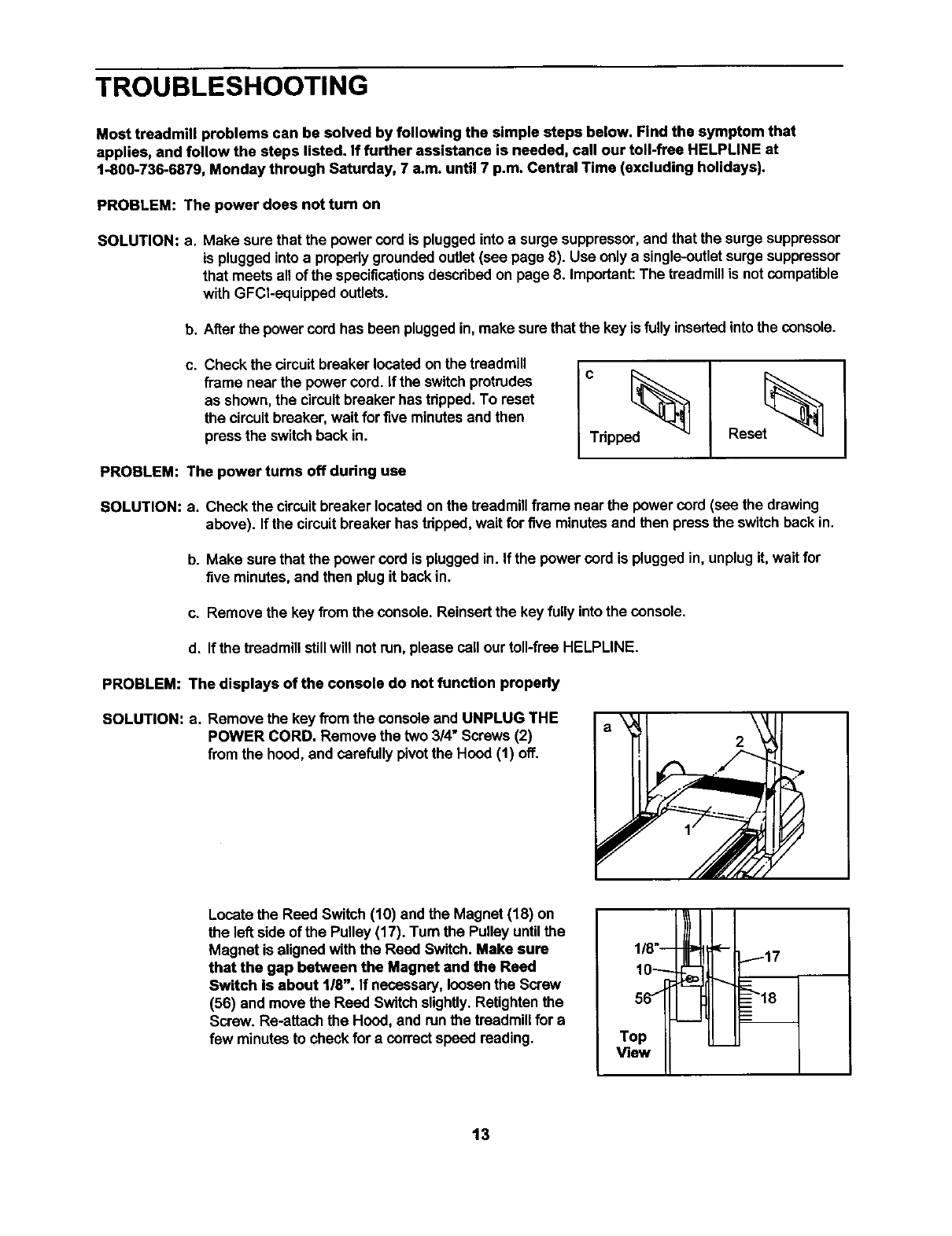
PROBLEM: The displays of the console do not function properly
SOLUTION: a. Remove the key from the console and UNPLUG THE
POWER CORD. Remove the two 3/4" Screws (2)
from the hood, and carefullypivotthe Hood (1) off.
Locate the Reed Switch (10) and the Magnet (18) on
the left side of the Pulley (17)oTurn the Pulley untilthe
Magnet is aligned withthe Reed Switch. Make sure
that the gap between the Magnet and the Reed
Switch Is about 1/8". If necessary, loosenthe Screw
(56) and move the Reed Switchslightly.Retightenthe
Screw. Re-attach the Hood, and runthe treadmillfor a
few minutes to check for a correctspeed reading.
118"--
10_
66
Top
View
17
13
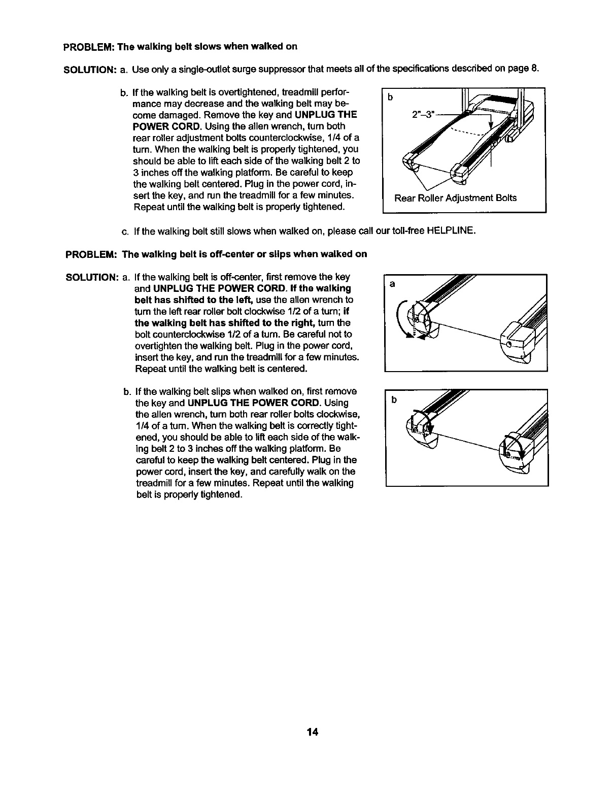
PROBLEM: The walking belt slows when walked on
SOLUTION: a. Use onlya single-outletsurge suppressorthat meetsall of the specificationsdescribed on page 8.
b_ If the walkingbelt is overtightened,treadmill perfor-
manca may decrease and the walkingbelt may be-
come damaged. Remove the key and UNPLUG THE
POWER CORD. Usingthe allen wrench, turn both
rear rolleradjustment bolts counterclockwise. 1/4 of a
turn. When the walking bolt is properly tightened, you
should be able to lift each side of the walking belt 2 to
3 inches off the walking platform. Be careful to keep
the walking belt centered. Plug in the power cord, in-
sert the key, and run the treadmill for a few minutes.
Repeat until the walking belt is propedy tightened.
b
Rear Roller Adjustment Bolts
c. If the walkingbelt still slows when walked on, please call our toll-free HELPLINE.
PROBLEM: The walking belt is off-center or slips when walked on
SOLUTION: a. If the walking belt is off-center,firstremovethe key
and UNPLUG THE POWER CORD. If the walking
belt has shifted to the left, use the allen wrenchto
tum the left rear rollerbolt clockwise1/2 of s turn; if
the walking belt has shifted to the right, tum the
bolt countemlockwise1/2 of a turn. Be careful notto
overtightenthe walking belt. Plugin the power cord,
insertthe key, and run the treadmillfora few minutes.
Repeat untilthe walking beltis cantered.
b. If the walkingbelt slipswhen walked on, firstremove
the key and UNPLUG THE POWER CORD. Using
the allen wrench,turn bothrear rollerboltsclockwise,
1/4 of a turn.When the walkingbelt is correctly tight-
ened, you shouldbe able to lifteach side of the walk-
ing belt2 to 3 inches offthe walking platform.Be
careful to keep the walkingbelt cantered. Plug in the
power cord,insertthe key, and carefullywalk onthe
treadmill for a few minutes. Repeat untilthe walking
belt is propedytightened.
b
14
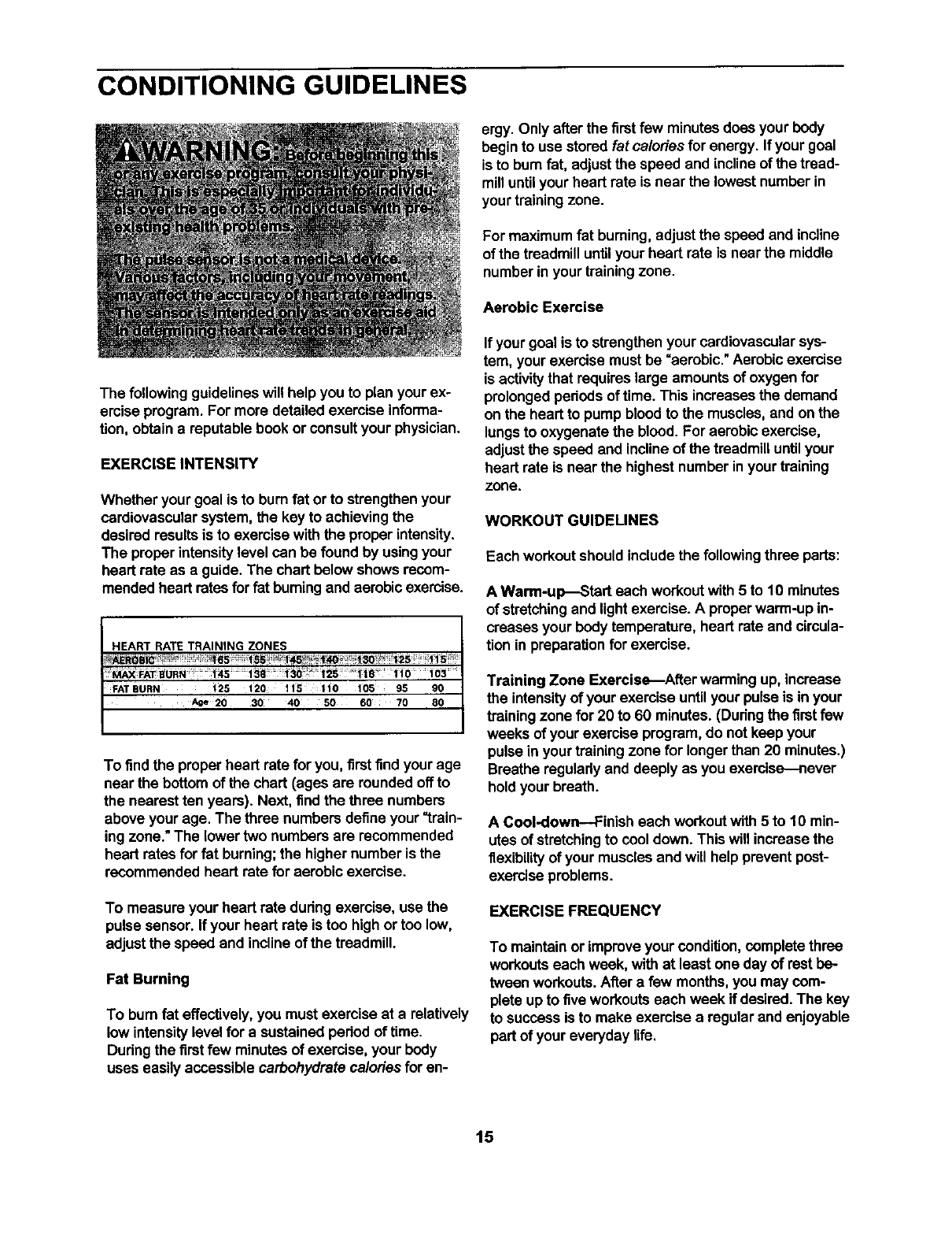
CONDITIONING GUIDELINES
The followingguidelines will help you to plan your ex-
emise program. For more detailedexercise informa-
tion, obtaina reputable book or consultyour physician.
EXERCISE INTENSITY
Whether your goal is to burnfat or to strengthenyour
cardiovascularsystem, the key to achievingthe
desired resultsis to exercise withthe proper intensity.
The proper intensitylevel can be found by usingyour
heart rate as a guide. The chart below shows recom-
mended heart rates forfat burningand aerobicexercise.
HEART RATE TRAINING ZONES
FATBURN _25 1_0 115 110 1B5 95 90
AOe¸20 30 40 50 60 70 80
To find the proper heart rate foryou, firstfind your age
near the bottom of the chart (ages are roundedoff to
the nearestten years). Next, find the three numbers
above your age. The three numbersdefine your "train-
ing zone." The lower two numbersare recommended
heart rates for fat burning;the highernumber is the
recommended heart rate for aerobic exercise.
To measure your heart rate during exercise, use the
pulse sensor. Ifyour heart rate istoo highor too low,
adjustthe speed and incline of the treadmill.
Fat Burning
To burnfat effectively, you must exercise at a relatively
low intensitylevel for a sustainedpedod of time.
Dudng the firstfew minutes of exercise, your body
uses easily accessible carbohydrate caloriesforen-
ergy. Only after the first few minutesdoes your body
begin to use stored fat calories for energy. If your goal
is to burnfat, adjustthe speed and incline of the tread-
milluntilyourheart rate is near the lowestnumber in
yourtrainingzone.
For maximum fat buming, adjust the speed and incline
of the treadmill untilyour heart rate is near the middle
numberin yourtrainingzone.
Aerobic Exercise
If yourgoal is to strengthenyour cardiovascularsys-
tem, your exercise mustbe "aerobic."Aerobicexercise
is activitythat requires large amounts of oxygen for
prolongedperiodsof time. This increases the demand
on the heart to pump bloodto the muscles,and on the
lungsto oxygenate the blood.For aerobicexercise,
adjustthe speed and inclineof the treadmilluntilyour
heart rate is near the highestnumber inyour training
zone.
WORKOUT GUIDELINES
Each workoutshouldincludethe followingthree parts:
A Warm-up--Start each workoutwith 5 to 10 minutes
of stretchingand lightexercise. A properwarm-up in-
creases your body temperature, heart rate and circula-
tion inpreparation for exercise.
Training Zone Exercise--After warming up, increase
the intensityof your exercise untilyour pulse is in your
trainingzone for 20 to 60 minutes. (Dudngthe firstfew
weeks of your exercise program,do not keep your
pulse in your trainingzone for longerthan 20 minutes.)
Breathe reguladyand deeply as you exercise_never
holdyour breath.
A Cool-down--Finish each workoutwith 5 to 10 min-
utes of stretchingto cool down. This will increase the
flexibilityof your musclesand will help prevent post-
exercise problems.
EXERCISE FREQUENCY
To maintainor improveyour condition,completethree
workoutseach week, withat least one day of rest be-
twean workouts.Aftera few months,you may com-
plete up to five workoutseach week if desired.The key
to success is to make exercise a regular and enjoyable
part of your everyday life.
15
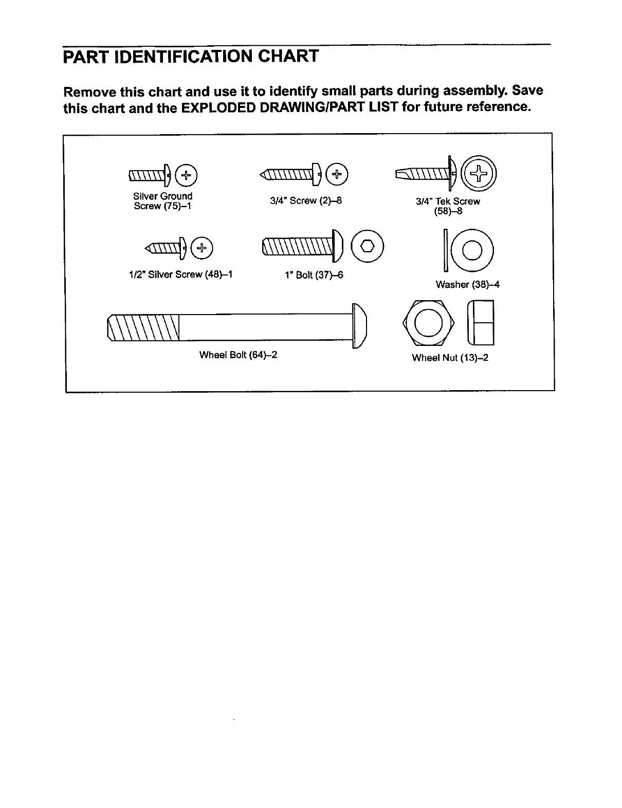
PART IDENTIFICATION CHART
Remove this chart and use it to identify small parts during assembly. Save
this chart and the EXPLODED DRAWING/PART LIST for future reference,
Silver Ground
Screw (75)-1 3/4" Screw (2)-8
1/2" Silver Screw (48)-1 1" Bolt(37)-6
Wheel Bolt (64)-2
3/4" Tek Screw
(58)-8
Washer (38)--4
Wheel Nut (13)-2
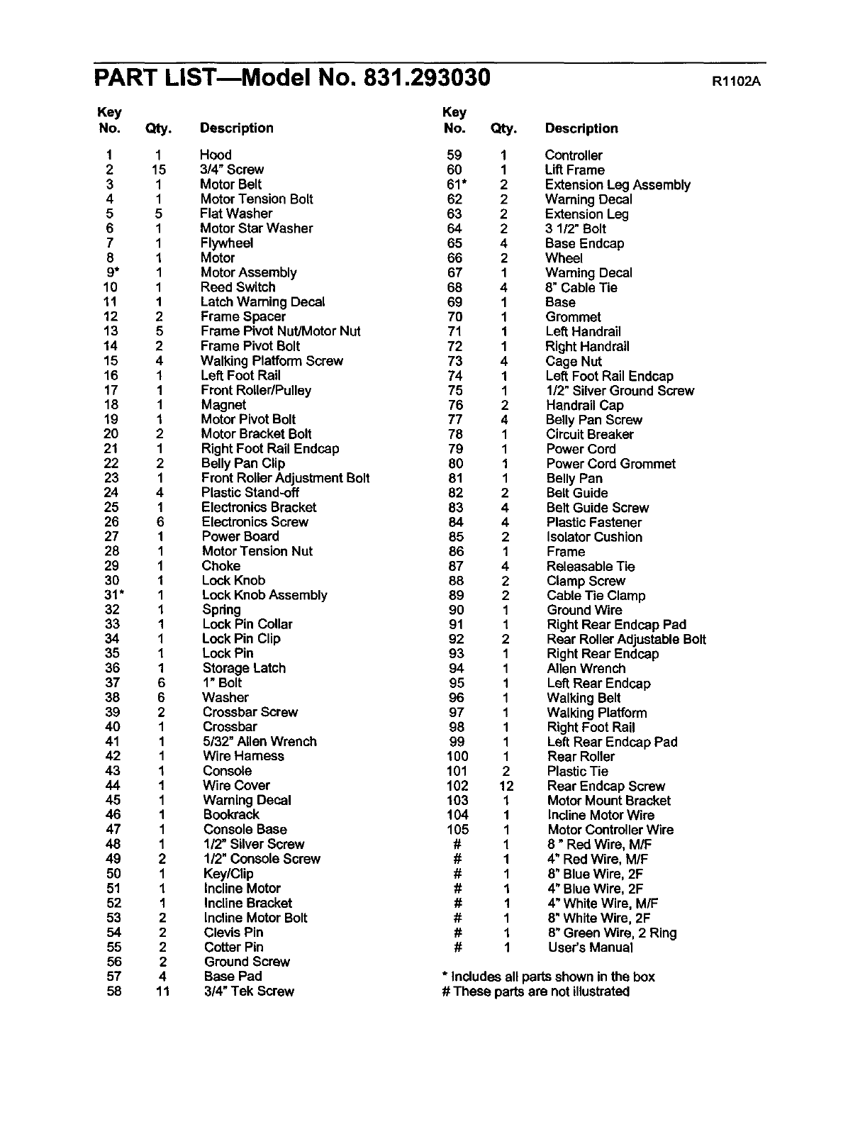
PART LISTmModel No. 831.293030 R1102A
Key Key
No. Qty. Description No.
1 1 Hood 59
2 15 3/4" Screw 60
3 1 Motor Belt 61"
4 1 Motor Tension Bolt 62
5 5 Flat Washer 63
6 1 Motor Star Washer 64
7 1 Flywheel 65
81Motor 66
9* 1 Motor Assembly 67
10 1 Reed Switch 68
11 1 Latch Warning Decal 69
12 2 Frame Spacer 70
13 5 Frame PivotNut/Motor Nut 71
14 2 Frame Pivot Bolt 72
15 4 Walking Platform Screw 73
16 1 Left Foot Rail 74
17 1 Front RoUer/Puney 75
18 1 Magnet 76
19 1 MotorPivot Bolt 77
20 2 Motor BracketBolt 78
21 1 Right Foot Rail Endcap 79
22 2 Belly Pan Clip 80
23 1 Front Roller Adjustment Bolt 81
24 4 PlasticStand,off 82
25 1 ElectronicsBracket 83
26 6 ElectronicsScrew 84
27 1 Power Board 85
28 1 Motor Tension Nut 86
29 1 Choke 87
30 1 Lock Knob 88
31" 1 Lock KnobAssembly 89
32 1 Spring 90
33 1 LockPin Collar 91
34 1 Lock Pin Clip 92
35 1 Lock Pin 93
36 1 Storage Latch 94
37 6 1" Bolt 95
38 6 Washer 96
39 2 CrossbarScrew 97
40 1 Crossbar 98
41 1 5/32" Allen Wrench 99
42 1 Wire Harness 100
43 1Console 101
44 1 Wire Cover 102
45 1 Waming Decal 103
46 1 Bookrack 104
47 1 Console Base 105
48 1 1/2"Silver Screw #
49 2 112"Console Screw #
50 1 Key/Clip #
51 1 Incline Motor #
52 1 Incline Bracket #
53 2 Incline MotorBolt #
54 2 Clevis Pin #
55 2 Cotter Pin #
56 2 Ground Screw
57 4 Base Pad
58 11 3/4"Tek Screw
Qty. Description
1 Controller
1 LiftFrame
2 ExtensionLeg Assembly
2 Warning Decal
2 ExtensionLeg
2 3 112"Bolt
4 Base Endcap
2 Wheel
1Waming Decal
4 8" Cable Tie
1 Base
1 Grommet
1 Left Handrail
1 RightHandrail
4 Cage Nut
1 Left Foot Rail Endcap
1 1/2" Silver Ground Screw
2 Handrail Cap
4 Belly Pan Screw
1 CircuitBreaker
1 Power Cord
1 Power Cord Grommet
1 Belly Pan
2 Belt Guide
4 Belt Guide Screw
4 Plastic Fastener
2 IsolatorCushion
1 Frame
4 Releasable Tie
2 Clamp Screw
2 Cable Tie Clamp
1 GroundWire
1 RightRear Endcap Pad
2 Rear Roller AdjustableBolt
1 RightRear Endcap
1 Allen Wrench
1 Left Rear Endcap
1 Walking Belt
1 Walking Platform
1 RightFoot Rail
1 Left Rear Endcap Pad
1Rear Roller
2 PlasticTie
12 Rear Endcap Screw
1 Motor MountBracket
1 InclineMotorWire
1 MotorControllerWire
1 8" Red Wire, M/F
1 4" Red Wire, M/F
1 8" Blue Wire, 2F
1 4" Blue Wire, 2F
1 4" White Wire, M/F
1 8" White Wire, 2F
1 8"Green Wire, 2 Ring
1 User's Manual
* Includes all partsshown in the box
# These partsare notillustrated

95
2
2
I0
45
B1
26
14
32
34 35
13
4O
65
13
54
69
42
73
73
CJ
o_

SEARS
Model No. 831.293030
QUESTIONS?
If you find that:
• you need help assembling or
operating the PROFORM 320x
treadmill
• a part is missing
• or you need to schedule repair
service
call our toll-free HELPLINE
1-800-736-6879
Monday-Saturday, 7 am-7 pm
Central Time (excluding holidays)
REPLACEMENT
PARTS
If parts become worn and need
to be replaced, call the following
toll-free number
t-800-FON-PART
(1-800-366-7278)
The model numberand sedal numberof your PROFORrvP320x
treadmill are listedon a decal attachedto the frame. See the front
cover of this manual to find the locationof the decal.
All replacementparts are availablefor immediate purchaseor
special orderwhen you visityour nearest SEARS Service Center.
To request service or to order partsby telephone, call the toll-free
numberslisted at the left.
When requesting help or service,or orderingparts, please be
prepared to provide the following information:
•The NAME OF THE PRODUCT (PROFORM®320x treadmill)
• The MODEL NUMBER OF THE PRODUCT (831.293030)
•The KEY NUMBER AND DESCRIPTION OF THE PART (see the
EXPLODED DRAWING end PART LIST inthe center of this
manual)
FULL 90 DAY WARRANTY
For 90 days from the date of purchase, if failureoccursdue to defect in matadalor workmanshipin this
SEARS TREADMILL EXERCISER, contactthe nearest SEARS ServiceCenter throughout the United
States and SEARS will repairor replacethe TREADMILL EXERCISER, free of charge.
This warrantydoes notapplywhen the TREADMILL EXERCISER is usedcommerciallyorfor rental pur-
poses.
This warranty gives you specificlegal rights, and you may also have other dghts which vary from state
to state.
Sears, Roebuck and Co., Dept. 817WA, Hoffman Estates, IL 60179
Part No. 189304 R1102A Printedin USA ©2002 Sears, Roebuckand Co.
