Proform 831293040 User Manual CROSSWALK 380X Manuals And Guides L0304221
PROFORM Treadmill Manual L0304221 PROFORM Treadmill Owner's Manual, PROFORM Treadmill installation guides
831.293040 L0304221
User Manual: Proform 831293040 831293040 PROFORM CROSSWALK 380X - Manuals and Guides View the owners manual for your PROFORM CROSSWALK 380X #831293040. Home:Fitness Equipment Parts:Proform Parts:Proform CROSSWALK 380X Manual
Open the PDF directly: View PDF ![]() .
.
Page Count: 27
CrossWalk
380×
Model No. 831.293040
Serial No.
Serial
Number
Decal
•Assembly
•Operation
•Maintenance
•Part List and Drawing
TREADMILL EXERCISER
User's Manual
Sears, Roebuck and Co., Hoffman Estates, IL 60179
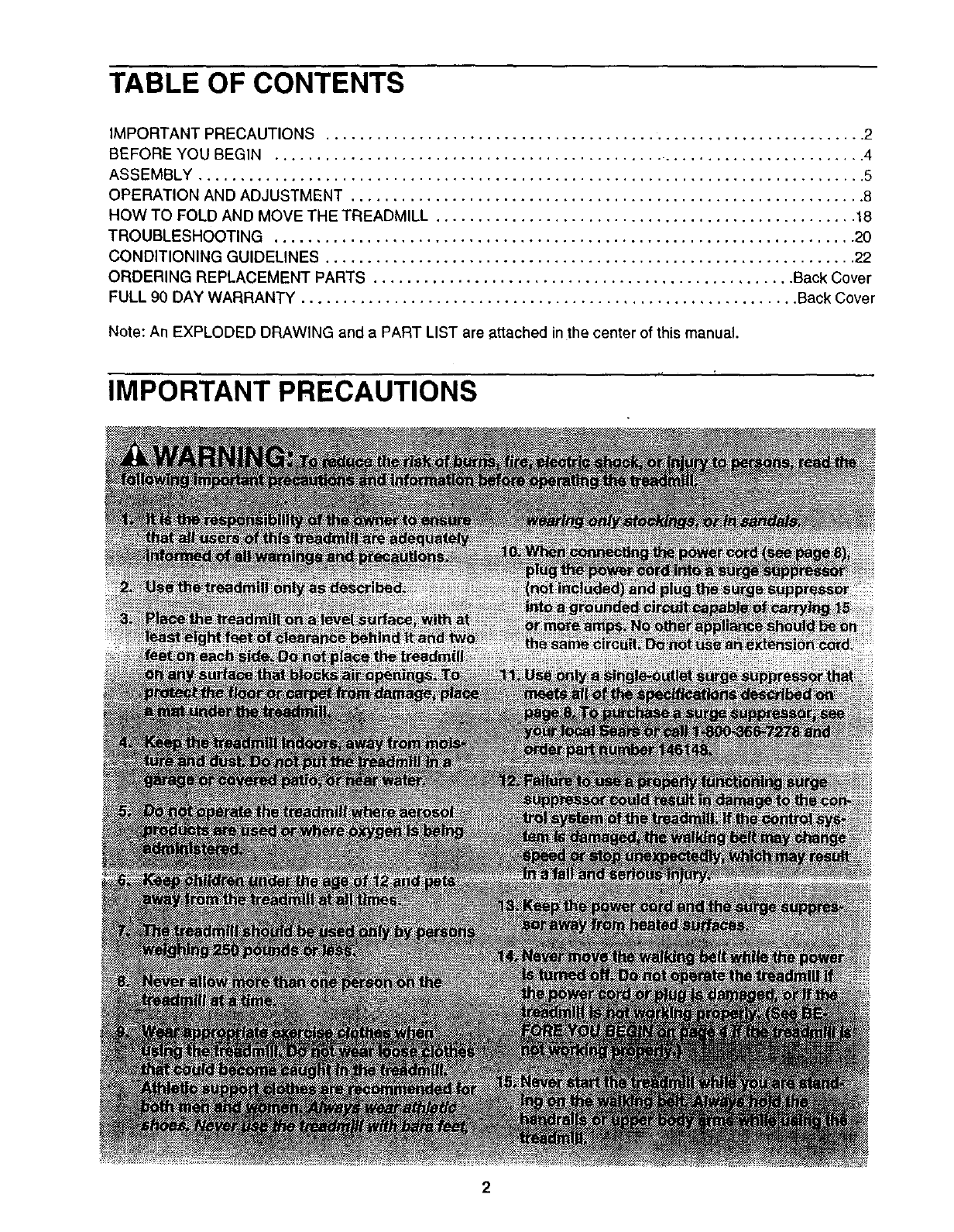
TABLE OF CONTENTS
IMPORTANT PRECAUTIONS ................................................................ 2
BEFORE YOU BEGIN ...................................................................... 4
ASSEMBLY ............................................................................... 5
OPERATION AND ADJUSTMENT ............................................................. 8
HOW TO FOLD AND MOVE THE TREADMILL .................................................. 18
TROUBLESHOOTING ..................................................................... 20
CONDITIONING GUIDELINES ............................................................... 22
ORDERING REPLACEMENT PARTS .................................................. Back Cover
FULL 90 DAY WARRANTY ........................................................... Back Cover
Note: An EXPLODED DRAWING and a PART L ST are attached n the center of this manual.
IMPORTANT PRECAUTIONS
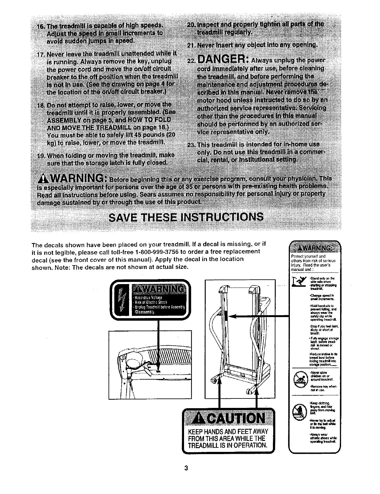
The decals shown have been placed on your treadmill. If a decal is missing, or if
it is not legibie, please call toll-free 1-800-999-3756 to order a free replacement
decal (see the front cover of this manual). Apply the decal in the location
shown. Note: The decals are not shown at actual size.
Protect yourself and
others from dsk of serious
iniury. Read the user's
_anuaJ and :
BEFORE YOU BEGIN
Thank you for selecting the revolutionary PROFORM*
CROSSWALK 380x treadmill. The CROSSWALK 380x
treadmill combines advanced technology with innova-
tive design to help you get the most from your exercise
program in the convenience and privacy of your home.
And when you're not exercising, the unique CROSS-
WALK 380x treadmill can be folded up, requiring less
than half the floor space of other treadmills.
For your benefit, read this manual carefully before
using the treadmill. If you have questions after read-
ing this manual, call 1-800-4-MY-HOME ° (1-800-469-
4663).To help us assist you, please note the product
model number and serial number before calling. The
model number of the treadmill is 831.293040. The ser-
ial number can be found on a decal attached to the
treadmill (see the front cover of this manual for the lo-
cation).
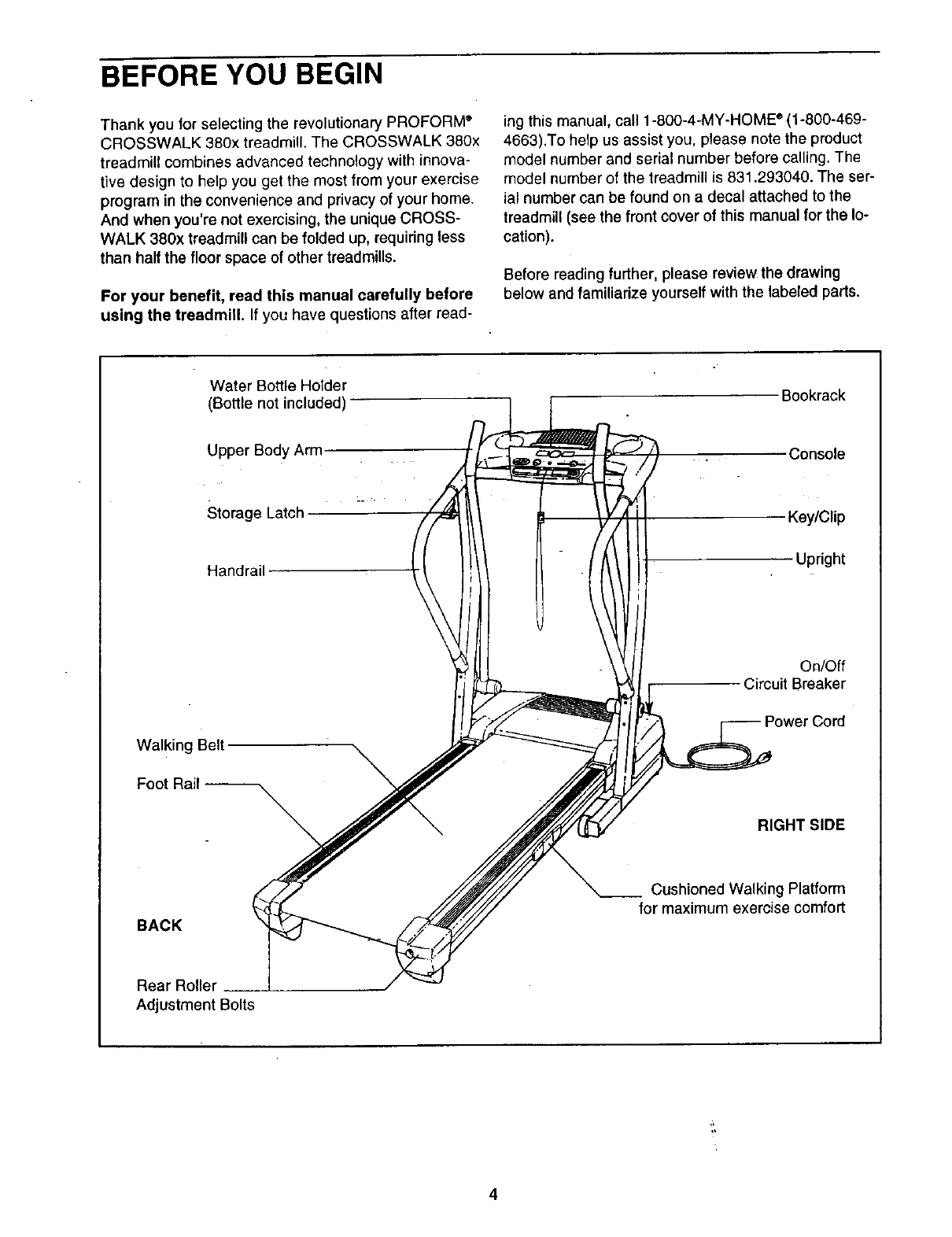
Before reading further, please review the drawing
below and familiarize yourself with the labeled pads,
Water Bottle Holder
(Bottle not included)
Upper Body Arm
Storage Latch
Handrail
Bookrack
Console
Key/Clip
Upright
On/Off
Circuit Breaker
Walking Belt
Foot Rail -- \\
RIGHT SIDE
BACK
Cushioned Walking Platform
for maximum exercise comfort
Rear Roller
Adjustment Bolts
4
ASSEMBLY
Assembly requires two persons. Set the treadmill in a cleared area and remove all packing materials. Do not
dispose of the packing materials until assembly is completed. Note: The underside of the treadmill walking belt is
coated with high-performance lubricant. During shipping, a small amount of lubricant may be transferred to the
top of the walking belt or the shipping carton. This is a normal condition and does not affect treadmill perfor-
mance. If there is lubricant on top of the walking belt, simply wipe off the lubricant with a soft cloth and a mild,
non-abrasive cleaner.
Assembly requires the included alien wr_ and your own phillips screwdriver _,
wire cutters _ , and needlenose pliers _ .
To identify small parts, use the PART IDENTIFICATION CHART attached in the center of this manual.
Note: If a part is not in the parts bag, first check to see it it has been pre-assembled. If a part is missing,
call toll-free 1-800-999-3756.
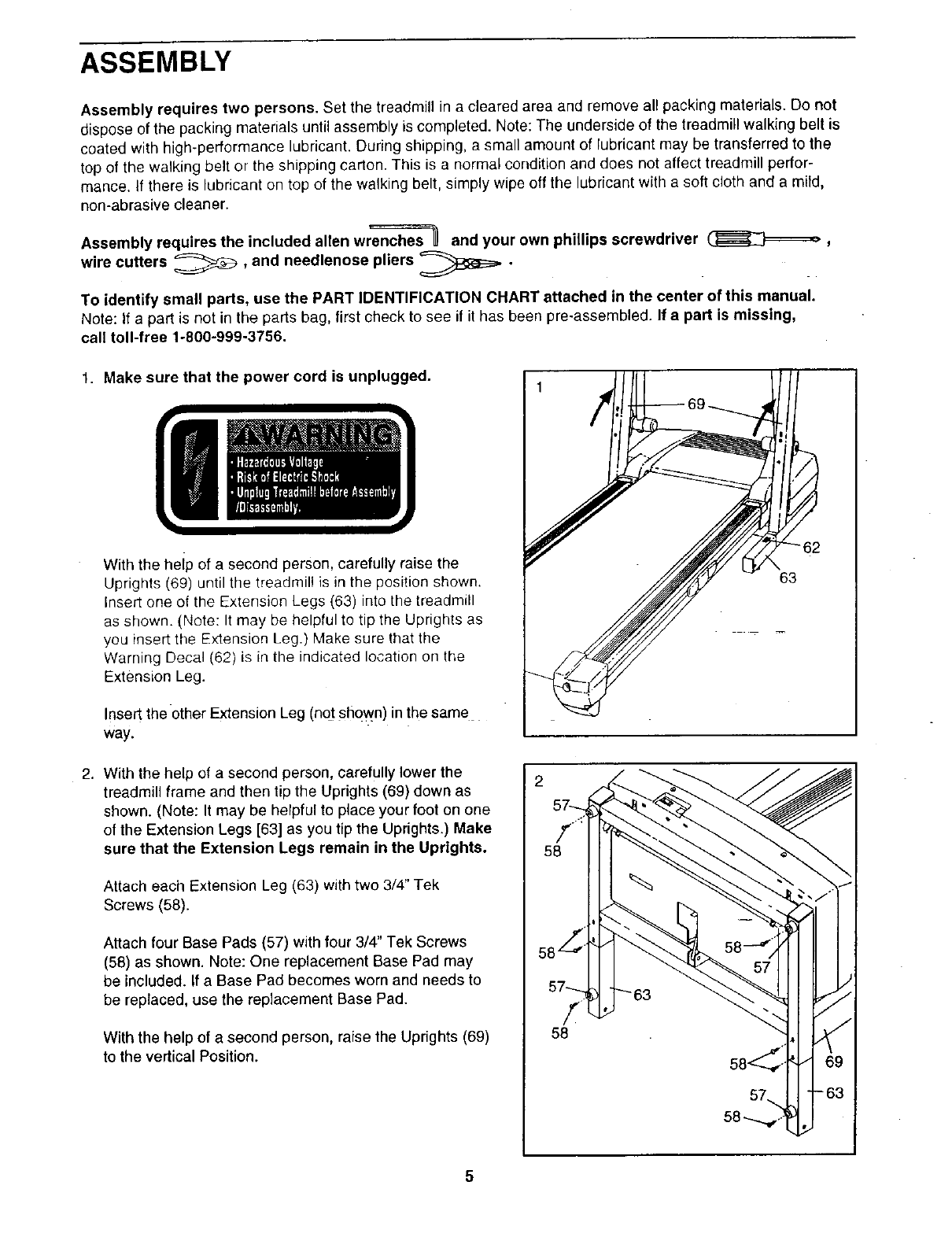
1. Make sure that the power cord is unplugged.
With the heip of a second person, carefully raise the
Uprights (69) until the treadmil! is in the position shown.
Insert one of the Extension Legs (63) into the treadmill
as shown. (Note: It may be helpful to tip the Uprights as
you insert the Extension Leg.) Make sure that the
Warning Decal (62) is in the indicated location on the
Extension Leg.
Insert the other Extension Leg (not shown) in the same
Way.
2. With the help of a second person, carefully lower the
treadmill frame and then tip the Uprights (69) down as
shown. (Note: It may be helpful to place your foot on one
of the Extension Legs [63] as you tip the Uprights.) Make
sure that the Extension Legs remain in the Uprights.
Attach each Extension Leg (63) with two 3/4" Tek
Screws (58).
Attach four Base Pads (57) with four 3/4" Tek Screws
(58) as shown. Note: One replacement Base Pad may
be included. If a Base Pad becomes worn and needs to
be replaced, use the replacement Base Pad.
With the help of a second person, raise the Uprights (69)
to the vertical Position.
2
57_.
58
58, i
57----._
58
i
fl
7)
63
58-_
5
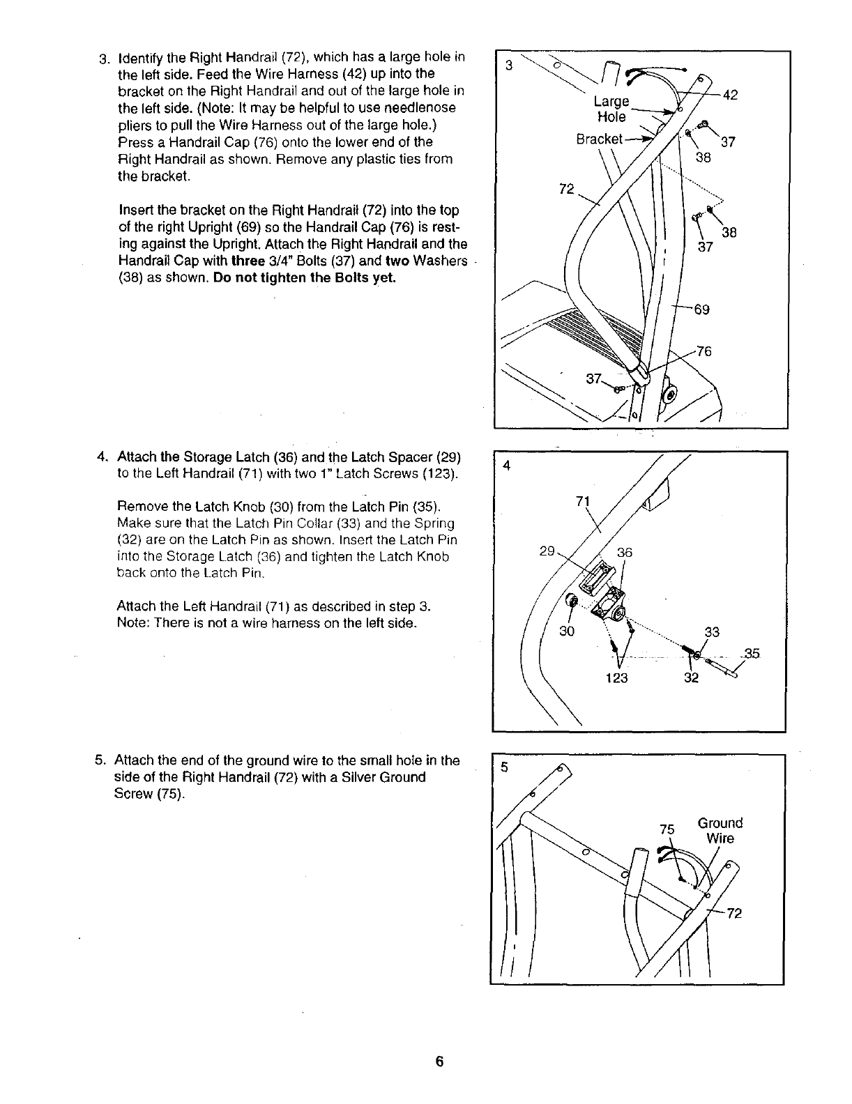
3. Identify the Right Handrail (72), which has a large hole in
the left side. Feed the Wire Harness (42) up into the
bracket on the Right Handrail and out of the large hole in
the left side. (Note: It may be helpful to use needlenose
pliers to pull the Wire Harness out of the large hole.)
Press a Handrail Cap (76) onto the lower end of the
Hight Handrail as shown. Remove any plastic ties from
the bracket.
Insert the bracket on the Right Handrail (72) into the top
of the right Upright (69) so the Handrail Cap (76) is rest-
ing against the UprighL Attach the Right Handrail and the
Handrail Cap with three 3/4" Bolts (37) and two Washers -
(38) as shown. De net tighten the Bolts yet.
3
38
37
4. Attach the Storage Latch (36) and the Latch Spacer (29)
to the Left Handrail (71) with two 1" Latch Screws (123).
Remove the Latch Knob (30) from the Latch Pin (35).
Make sure that the Latch Pin Collar (33) and the Spring
(32) are on the Latch Pin as shown. Insert the Latch Pin
into the Storage Latch (36) and tighten the Latch Knob
back onto the Latch Pin.
Attach the Left Handrail (71) as described in step 3.
Note: There is not a wire harness on the left side.
4
71
\
29,, 36
123
5. Attach the end of the ground wire to the small hole in the
side of the Right Handrail (72) with a Silver Ground
Screw (75).
75 Ground
Wire
6
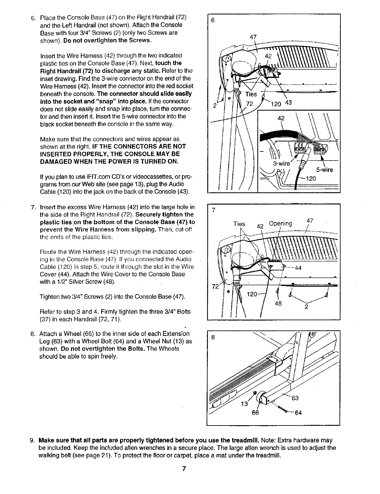
6 Place the Console Ease (47) on the Right Handrail (72)
and the Left Handrail (not shown). Attach the Console
Base with four 3/4" Screws (2) (only two Screws are
shown). Do not overtighten the Screws.
Insert the Wire Harness (42) through the two indicated
plastic ties on the Console Ease (47). Next, touch the
Right Handrail (72) to discharge any static. Refer to the
inset drawing. Find the 3-wire connector on the end of the
Wire Hamess (42). Insert the connector into the red socket
beneath the console. The connector should slide easily
into the socket and "snap" into place. If the connector
does not slide easily and snap into place, turn the connec-
tor and then insert it. insert the 5-wire connector into the
black socket beneath the console in the same way.
Make sure that the connectors and wires appear as
shown at the right. IF THE CONNECTORS ARE NOT
INSERTED PROPERLY, THE CONSOLE MAY BE
DAMAGED WHEN THE POWER IS TURNED ON.
If you plan to use iFIT.com CD's or videocassettes,or pro-
grams from our Web site (see page 13), plugthe Audio
Cable (120) intothe jack on the back of the Console (43).
7. Insert the excess Wire Harness (42) into the large hole in
the side of the Right Handrail (72). Securely tighten the
plastic ties .on the bottom of the Console Base (47) to
prevent the Wire Harness from slipping. Then, cut off
the ends of the plastic ties.
Route the Wire Harness (42) through the indicated open-
ing in the Console Base (47). If you connected the Audio
Cable (120) in step 5, route it through the slot in the Wire
Cover (44). Attach the Wire Cover to the Console Base
with a 1/2" Silver Screw (48).
Tighten two 3/4" Screws (2) into the Console Base (47).
Refer to step 3 and 4. Firmly tighten the three 3/4" Bolts
(37) in each Handrail (72, 71).
8. Attach a Wheel (66) to the inner side of each Extension
Leg (63) with a Wheel Bolt (64) and a Wheel Nut (13) as
shown. Do not overtighten the Bolts. The Wheels
should be able to spin freely.
6
2
7;
8
Ties
47
_120
47
48 2
9. Make sure that all parts are properly tightened before you use the treadmill. Note: Extra hardware may
be included. Keep the included allen wrenches in a secure place. The large allen wrench is used to adjust the
walking belt (see page 21). To protect the floor or carpet, place a mat under the treadmill.
7
OPERATION AND ADJUSTMENT
THE PERFORMANT LUBE TM WALKING BELT
Your treadmill features a walking belt coated with
PERFORMANT LUBE TM, a high-performance lubricant.
IMPORTANT: Never apply silicone spray or other
substances to the walking belt or the walking plat-
form. Such substances will deteriorate the walking
belt and cause excessive wear.
HOW TO PLUG IN THE POWER CORD
an equipment-grounding conductor and agrounding
plug. Plug the power cord into a surge suppressor,
and plug the surge suppressor into an appropriate
outlet that is properly installed and grounded in
accordance with all local codes and ordinances.
Important: The treadmill is not compatible with
GFCI-equipped outlets,
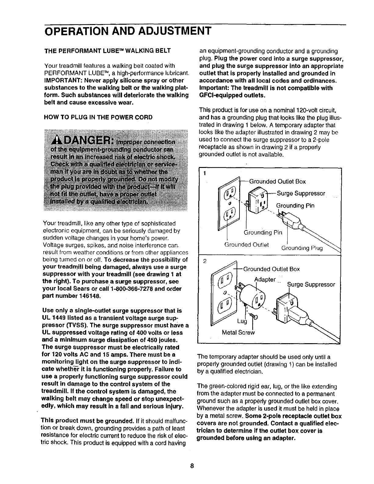
This product is for use on a nominal 120-volt circuit,
and has a grounding plug that looks likethe plug illus=
trated in drawing 1 below. A temporary adapter that
looks like the adapter illustrated in drawing 2may be
used to connect the surge suppressor to a 2-pole
receptacle as shown in drawing 2if a properly
grounded outlet is not available.
Your treadmill, like any other type of sophisticated
electronic equipment, can be seriously damaged by
sudden voltage changes in your home's power.
Voltage surges, spikes, and noise intederence can.
result from weather conditions or from other appliances
being turned on or off. TO decrease the possibility of
your treadmill being damaged, always use a surge
suppressor with your treadmill (see drawing 1 at
the right). To purchase a surge suppressor, see
your local Sears or call 1-800-366-7278 and order
part number 146148.
Use only a single-outlet surge suppressor that is
UL 1449 listed as a transient voltage surge sup-
pressor (TVSS). The surge suppressor must have a
UL suppressed voltage rating of 400 volts or less
and a minimum surge dissipation of 450 joules.
The surge suppressor must be electrically rated
for 120 volts AC and 15 amps. There must be a
monitoring light on the surge suppressor to indi-
cate whethe¥ it is functioning properly. Failure to
use a properly functioning surge suppressor could
result in damage to the control system of the
treadmill. If the control system is damaged, the
walking belt may change speed or stop unexpect-
edly, which may result in a fall and serious injury.
This product must be grounded. If it should malfunc-
tion or break down, grounding provides a path of least
resistance for electric current to reduce the riskof elec-
tric shock. This product is equipped with a cord having
2
Grounded Outlet Box
?-I _Surge Suppressor
°p_'_... Grounding Pin
Grounding Pin
Grounded Outlet Grounding
Grounded Outlet Box
Adapter
"_Surge suppressor
Metal Screw
The temporary adapter should be used only untila
properly grounded outlet (drawing 1) can be installed
by a qualified electrician.
The green-colored rigid ear, lug, or the like extending
from the adapter must be connected to a permanent
ground such as a properly grounded outlet box cover.
Whenever the adapter is used it must be held in place
by a metal screw. Some 2-pole receptacle outlet box
covers are not grounded. Contact a qualified elec-
trician to determine if the outlet box cover is
grounded before using an adapter.
8
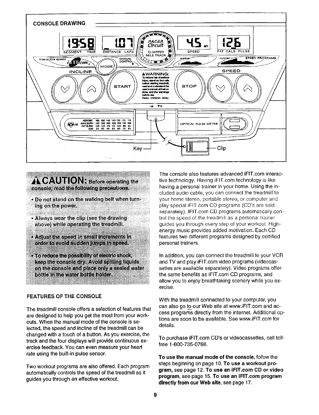
CONSOLE DRAWING
Key -- Clip
FEATURES OF THE CONSOLE
The treadmill console offers a selection of features that
are designed to help you get the most from your work-
outs. When the manual mode of the console is se-
lected, the speed and incline of the treadmill can be
changed with a touch of a button. As you exercise, the
track and the four displays will provide continuous ex-
ercise feedback. You can even measure your heart
rate using the built-in pulse sensor.
Two workout programs are also offered. Each program
automatically controls the speed of the treadmill as it
guides you through an effective workout.
The console also features advanced iFIT.com interac-
tive technology. Having iFIT.com technology is like
having a personal trainer in your home. Using the in-
cluded audio cable, you can connect the treadmil[to
your home stereo, portable stereo, or computer and
play special iFIT.com CD programs (CD's are sold
separately), lFIT.com CD programs automaticallycon-
trol the speed of the treadmill as a personal trainer
guides you through every step of your workout. High-
energy music provides added motivation. Each CD
features two different programs designed by certified
personal trainers.
In addition, you can connect the treadmill to your VCR
and TV and play iFIT.com video programs (videocas-
series are available separately). Video programs offer
the same benefits as iFIT.com CD programs, and
allow you to enjoy breathtaking scenery while you ex-
ercise.
With the treadmill connected to your computer, you
can also go to our Web site at www.iFIT.com and ac-
cess programs directly from the internet. Additional op-
tions are soon to be available. See www.iFIT.com for
details.
To purchase iFIT.com CD's or videocassettes, call toll-
free 1-800-735-0768.
To use the manual mode of the console, follow the
steps beginningon page 10. To use a workout pro-
gram, see page 12. To use an iFIT.com CD or video
program, see page 15. To use an IFIT.com program
directly from our Web site, see page 17.
HOW TO TURN ON THE POWER
Note: If there is a thin sheet of clear plastic on the con-
sole, remove the plastic.
_lPlug in the power cord (see page 8).
suit breaker on the
front of the treadmill
near the power cord. Reset
Make sure that the
breaker is in the reset
position.
Stand on the foot rails
of the treadmill. Find
the clip attached to the
key, and slide the clip
onto the waistband of
your clothes. Next, in-
sert the key into the
console. After a mo-
ment, the displays and
various indicators on
the console will light.
Test the clip by care-
IA VO
_o,
fully taking a few steps backward until the key
is pulled from the console. If the key is not
pulled from the console, adjust the position of
the clip as_needed.
DInsert the key fully into the console.
See HOW TO TURN ON THE POWER above.
BSelect the manual mode.
When the key is in- ISTANCE LAPS
serted, the manua{ _EAL:: LLI_JMANu_
mode will automatically I"_ c°_mo%\_
be selected and the
Manual Control indica-
tor will light. If a pro-
gram has been selected, press the Mode button
repeatedly to select the manual mode.
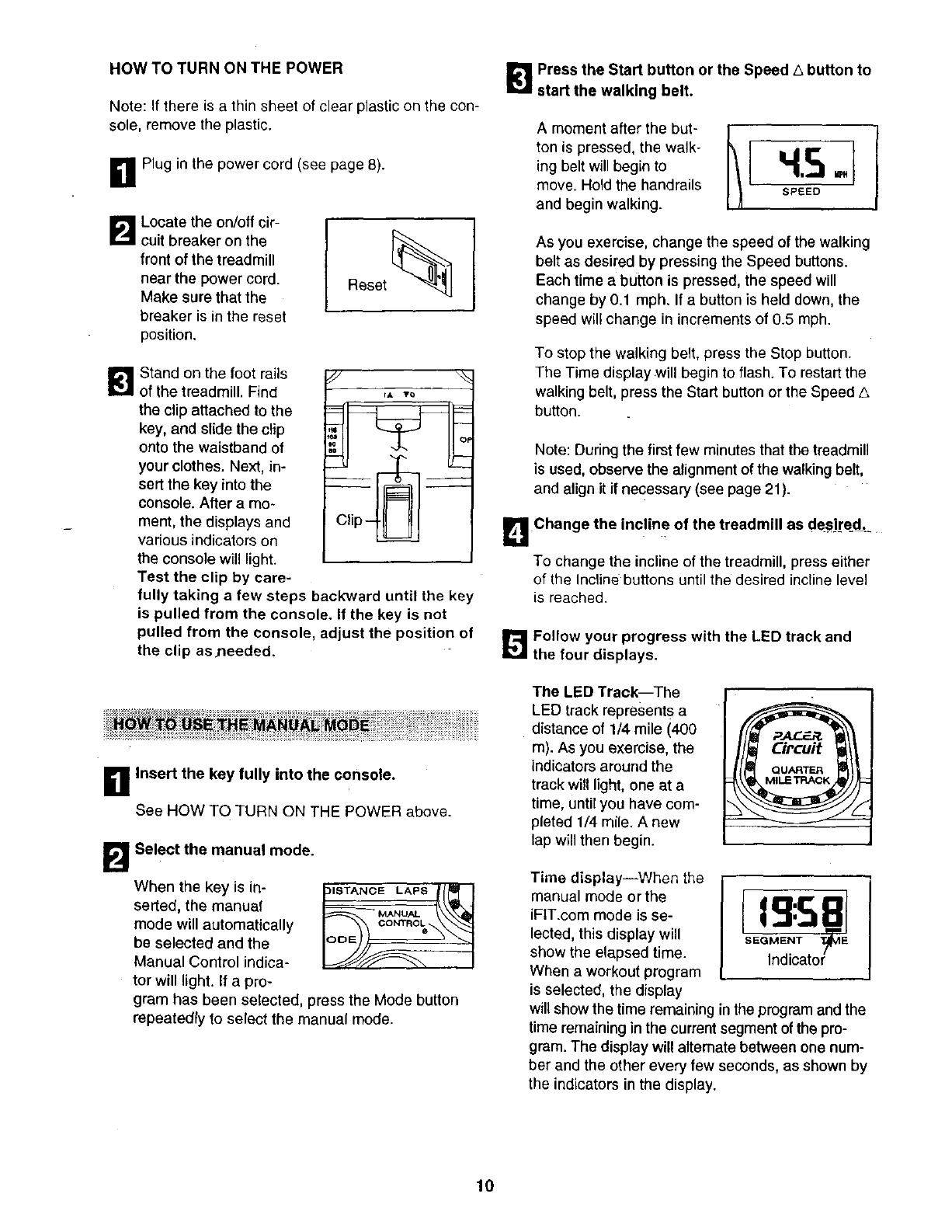
[]Press the Start button or the Speed .,3button to
start the walking belt.
A moment after the but-
ton is pressed, the walk-
ing belt will begin to
move. Hold the handrails
and begin walking.
As you exercise, change the speed of the walking
belt as desired by pressing the Speed buttons.
Each time a button is pressed, the speed will
change by 0.1 mph, If a button is held down, the
speed will change in increments of 0.5 mph.
To stop the walking belt, press the Stop button.
The Time display will begin to flash. To restart the
walking belt, press the Start button or the Speed A
button.
Note: During the first few minutes that the treadmill
is used, observe the alignment of the walking belt,
and align it if necessary (see page 21).
Change the incline of the treadmill as de.sire=d..
To change the incline of the treadmill, press either
of the Incline buttons until the desired incline level
is reached.
[]Follow your progress with the LED track and
the four displays.
The LED Track--The
LED track represents a
distance of 1/4 mile (400
m). As you exercise, the
indicators around the
track will light, one at a
time, until you have com-
pleted 1/4 mile. A new
lap will then begin.
Time display--When the
manual mode or the
iFIT.com mode is se-
lected, this display will
show the elapsed time.
When a workout program
is selected, the display
will show the time remaining in the program and the
time remaining in the current segment of the pro-
gram. The display will alternate between one num-
ber and the other every few seconds, as shown by
the indicators in the display.
10
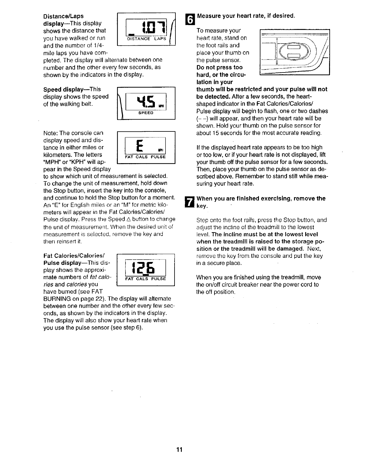
Distance/Laps I
display--This display
shows the distance that
you have walked or run
and the number of 1/4-
mile laps you have com-
pleted. The display will alternate between one
number and the other every few seconds, as
shown by the indicators in the display.
Speed display--This
display shows the speed
of the walking belt.
_, I,D 3J _ B Measure y°ur heart rate' if desired"
CISTANCE LAPS
H.5o
SPEED
Note: The console can
display speed and dis" I E1tance in either miles or
kilometers. The letters PATCABSPUBSE
"MPH" or "KPH" will ap-
pear in the Speed display
to show which unit of measurement is selected.
To change the unit of measurement, hold down
the Stop button, insert the key into the console,
and continue to hold the Stop button for a moment.
An "E" for English miles or an "M" for metric kilo-
meters will appear in the Fat Calories/Calories/
Pulse display. Press the Speed A button to change
the unit of measurement. When the desired unit of
measurement is selected, remove the key and
then reinsert it.
1r=2_sl
PAT CABS PULSE
Fat Calories/Calories/
Pulse display--This dis-
play shows the approxi-
mate numbers of fat calo-
ries and calories you
have burned (see FAT
BURNING on page 22). The display will altemate
between one number and the other every few sec-
onds, as shown by the indicators in the display.
The display will also show your heart rate when
you use the pulse sensor (see step 6).
To measure your
heart rate, stand on
the foot rails and
place your thumb on
the pulse sensor.
Do not press too
hard, or the circu-
lation in your
thumb will be restricted and your pulse will not
be detected. After afew seconds, the heart-
shaped indicator in the Fat Calories/Calories/
Pulse display will begin to flash, one or two dashes
(- -) will appear, and then your heart rate will be
shown. Hold your thumb on the pulse sensor for
about 15 seconds for the most accurate reading.
If the displayed heart rate appears to be too high
or too low, or if your heart rate is not displayed, lift
your thumb off the pulse sensor for a few seconds.
Then, place your thumb on the pulse sensor as de-
scribed above. Remember to stand still while mea-
suring your heart rate.
B When you are finished exercising, remove the
key.
Step onto the foot rails, press the Stop button, and
adjust the incline of the treadmill to the lowest
level. The incline must be at the lowest level
when the treadmill is raised to the storage po-
sition or the treadmill will be damaged. Next,
remove the key from the console and put the key
in a secure place.
When you are finished using the treadmill, move
the on/off circuit breaker near the power cord to
the off position.
11
_! Insert the key into the console.
See HOW TO TURN ON THE POWER on 10.
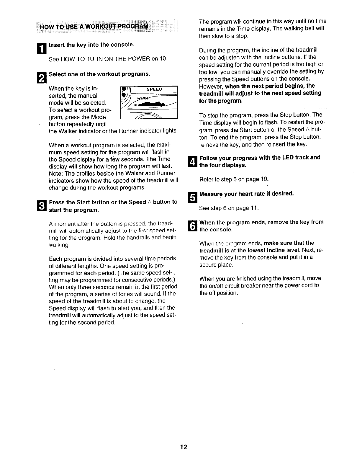
BSelect one of the workout programs.
When the key is in-
serted, the manual
mode will be selected.
To select a workout pro-
gram, press the Mode
button repeatedly until
SPEEO
IIIker
the Walker indicator or the Runner indicator lights.
When a workout program is selected, the maxi-
mum speed setting for the program will flash in
the Speed display for a few seconds. The Time
display will show how long the program will last.
Note: The profiles beside the Walker and Runner
indicators show how the speed of the treadmill will
change during the workout programs.
_1 Press the Start button or the Speed _, button to
start the program.
A moment after the button is pressed, the tread-
mill will automatically adjust to the first speed set-
ting for the program. Hold the handrails and begin
walking.
Each program is divided into several time periods
of different lengths. One speed setting is pro-
grammed for each period. (The same speed set-
ting may be programmed for consecutive periods.)
When only three seconds remain in the first period
of the program, a series of tones will sound. If the
speed of the treadmill is about to change, the
Speed display will flash to alert you, and then the
treadmill will automatically adjust to the speed set-
ting for the second period.
The program will continue in this way until no time
remains in the Time display. The walking belt will
then slow to a stop.
During the program, the incline of the treadmill
can be adjusted with the Incline buttons. If the
speed setting for the current period is too high or
too low, you can manually override the setting by
pressing the Speed buttons on the console.
However, when the next period begins, the
treadmill will adjust to the next speed setting
for the program.
To stop the program, press the Stop button. The
Time display will begin to flash. To restart the pro-
gram, press the Start button or the Speed A but-
ton. To end the program, press the Stop button,
remove the key, and then reinsert the key.
DFollow your progress with the LED track and
the four displays.
Refer to step 5 on page 10.
Measure your heart rate if desired.
See step6 on page 11.
When the program ends, remove the key from
the console.
When the program ends, make sure that the
treadmill is at the lowest incline level. Next, re-
move the key from the console and put it in a
secure place.
When you are finished using the treadmill, move
the on/off circuit breaker near the power cord to
the off position.
12
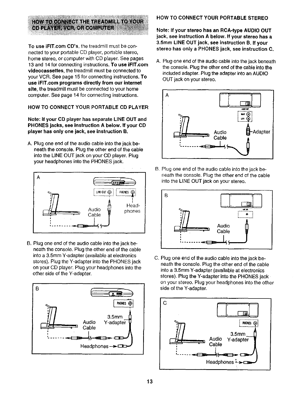
To use iFIT.com CD's, the treadmill must be con-
nected to your portable CD player, portable stereo,
home stereo, or computer with CD player. See pages
13 and 14 for connecting instructions. To use iFIT.com
videocassettes, the treadmill must be connected to
your VCR. See page 15 for connecting instructions. To
use iFIT.com programs directly from our internet
site, the treadmill must be connected to your home
computer. See page 14 for connecting instructions.
HOW TO CONNECT YOUR PORTABLE CD PLAYER
Note: If your CD player has separate LINE OUT and
PHONES jacks, see instruction A below. If your CD
player has only one jack, see instruction B.
A. Plug one end of the audio cable into the jack be-
neath the console. Plug the other end of the cable
into the LINE OUT jack on your CD player. Plug
your headphones into the PHONES jack.
A
_/ I_1 Head-
F--'/:JIAudio _ phones
_ " Cable _ -
:........
B. Plug one end of the audio cable into the jack be-
neath the console. Plug the other end of the cable
into a 3.5mm Y-adapter (available at electronics
stores). Plug the Y-adapter into the PHONES jack
on your CD player. Plug your headphones into the
other side of the Y-adapter.
B
,[.
,, 3. mm
,'--'_,I I Audio Y-adapter_
.,I Cable /
....... Headphones --->-_
HOW TO CONNECT YOUR PORTABLE STEREO
Note: If your stereo has an RCA-type AUDIO OUT
jack, see instruction A below. If your stereo has a
3.5mm LINE OUT jack, see instruction B. If your
stereo has only a PHONES jack, see instruction C.
A. Plug one end of the audio cable into the jack beneath
the console. Plug the other end of the cable into the
included adapter. Plug the adapter into an AUDIO
OUT jack on your stereo.
A
_0ul
'I
Audio Adapter
Cable
B. Plug one end of the audio cable into the jack be-
neath the console. Plug the other end of the cable
into the LINE OUT jack on your stereo.
B
: o !
Audio
Cable
i
'II
I........ _ j_
•i
C. Plug one end of the audio cable into the jack be-
neath the console. Plug the other end of the cable
into a 3.5mm Y-adapter (available at electronics
stores). Plug the Y-adapter into the PHONES jack
on your stereo. Plug your headphones into the other
side of the Y-adapter.
C
'Ill 3.,mm
I--'/;,_I,, Audio Y-adapter |
_....._ " Cable
13
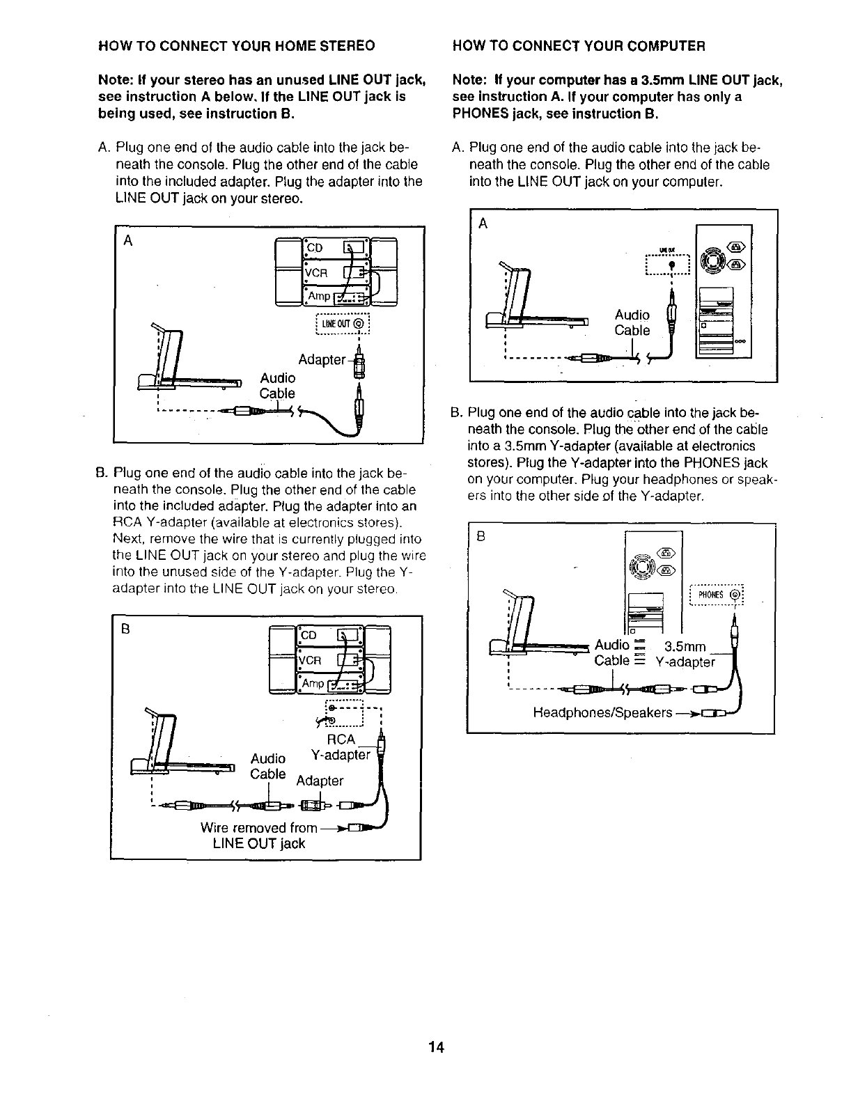
HOW TO CONNECT YOUR HOME STEREO
Note: If your stereo has an unused LINE OUT jack,
see instruction A below, If the LINE OUT jack is
being used, see instruction B.
A. Plug one end of the audio cable into the jack be-
neath the console. Plug the other end of the cable
into the included adapter. Plug the adapter into the
LINE OUT jack on your stereo.
A
iLtXEOUT@ !
' Adapter_...........I'-_"=
f--'/'/ I.Audio ==
"cable J[
......
B. Plug one end of the audio cable into the jack be-
neath the console. Plug the other end of the cable
into the included adapter- Plug the adapter into an
RCA Y-adapter (available at electronics stores}.
Next, remove the wire that is currently plugged into
the LINE OUT jack on your stereo and plug the wire
into the unused side of the Y-adapter. Plug the Y-
adapter into the LINE OUT jack on your stereo.
,;.'_-'_--.-_..,
,,
I// RCA_
_,'/, IAudio Y-adapter W
* " Cable Adapter
Wire removed from _
LINE OUT jack
HOW TO CONNECT YOUR COMPUTER
Note: If your computer has a 3.5ram LINE OUT jack,
see instruction A. If your computer has only a
PHONES jack, see instruction B.
A. Plug one end of the audio cable into the jack be-
neath the console. Plug the other end of the cable
into the LINE OUT jack on your computer.
A
umex
I_,_ Audio _[
_ Cable y
......... J
m
'-&L_t<A>
=======::=_
B. Plug one end of the audio c#.ble into the jack be-
neath the console. Plug the other end of the cable
into a 3.5mm Y-adapter (available at electronics
stores). Plug the Y-adapter into the PHONES jack
on your computer. Plug your headphones or speak-
ers into the other side of the Y-adapter.
B m
_[P,0,Es®i
Ill
I'_,_t!-,_-_,,-_ Audio _ 3.5ram V
_ Cable-------Y-adapte_ 4
Headphones/Speakers
14
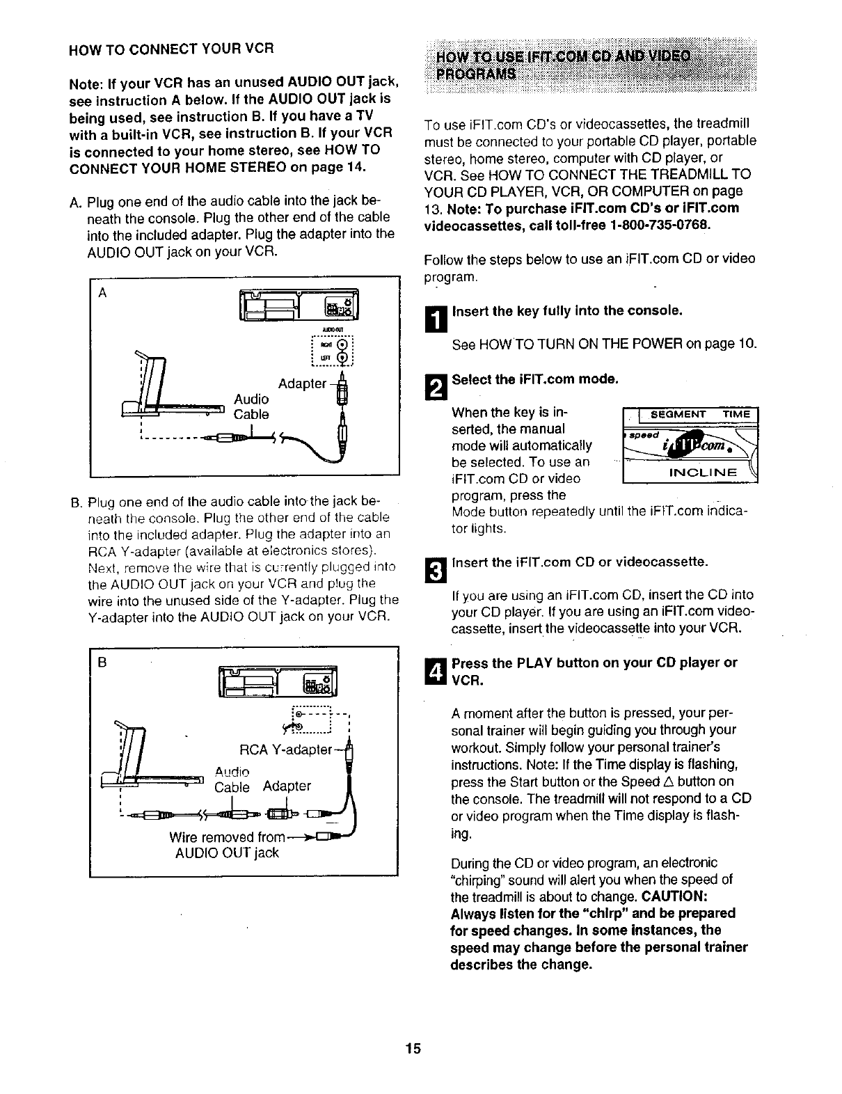
HOW TO CONNECT YOUR VCR
Note: If your VCR has an unused AUDIO OUT jack,
see instruction A below. If the AUDIO OUT jack is
being used, see instruction B. If you have a TV
with abuilt-in VCR, see instruction B. If your VCR
is connected to your home stereo, see HOW TO
CONNECT YOUR HOME STEREO on page 14.
A. Plug one end of the audio cable into the jack be-
neath the console. Plug the other end of the cable
into the included adapter. Plug the adapter into the
AUDIO OUT jack on your VCR.
A
1118_t4_
;//I Adapter q_
r--'_l IAudio
-" Cable IT_
......... -_,=_,_ __,_
B. Plug one end of the audio cable intothe jack be-
neath the console. Plug the other end of the cable
into the included adapter. Plug the adapter into an
RCA Y-adapter (available at electronics stores).
Next, remove the wire that is currently plugged into
the AUDIO OUT jack on your VCR and ptug the
wire into the unused side of the Y-adapter. Plug the
Y-adapter into the AUDIO OUT jack on your VCR.
B
..%:-:-:-:--..
:
I//,it# - RCA Y'adapter t
[_fJ IAudio !
Cable Adapter
Wire removed from---_,4z_=-"
AUDIO OUT jack
To use iFIT.com CD's or videocassettes, the treadmill
must be connected to your portable CD player, portable
stereo, home stereo, computer with CD player, or
VCR. See HOW TO CONNECT THE TREADMILL TO
YOUR CD PLAYER, VCR, OR COMPUTER on page
13. Note: To purchase iFIT.com CD's or iFIT.com
videocassettes, call toll-free 1-800-735-O768.
Follow the steps below to use an iFIT.com CD or video
program.
Insert the key fully into the console.
See HOWTO TURN ON THE POWER on page 10.
B Select the iFIT.com mode.
When the key is in-
serted, the manual
mode will automatically
be selected. To use an
iFtT.com CD or video F
program, press the
Mode button repeatedly until the iFIT.com indica-
tor lights.
_'1 Insert the iFIT.com CD or videocassette.
If you are using an iPIT.com CD, insert the CD into
your CD player. If you are using an iFIT.com video-
cassette, insert the videocassette into your VCR.
B Press the PLAY button on your CD player or
VCR.
A moment after the button is pressed, your per-
sonal trainer will begin guiding you through your
workout. Simply follow your personal trainer's
instructions. Note: If the Time display is flashing,
press the Start button or the Speed ,5 button on
the console. The treadmill will not respond to a CD
or video program when the Time display is flash-
ing.
During the CD or video program, an electronic
"chirping" sound will alert you when the speed of
the treadmill is about to change. CAUTION:
Always listen for the "chirp" and be prepared
for speed changes. In some instances, the
speed may change before the personal trainer
describes the change.
15
If the speed setting is too high or too low, you can
manually override the setting at any time by
pressing the Speed buttons on the console.
However, when the next "chirp" is heard, the
speed will change to the next setting for the CD
or video program.
To stop the walking belt at any time, press the
Stop button on the console. The Time display will
begin to flash. To restart the program, press the
Start button or the Speed a button. After a mo-
ment, the walking belt will begin to move at 1.0
mph. When the next "chirp" is heard, the
speed will change to the next setting for the
CD or video program.
When the CD or video program is completed, the
walking belt will stop and the Time display will
begin to flash. Note: To use another CD or video
program, press the Stop button or remove the key
and go to step 1 on page 15.
Note: if the speed of the treadmill does not
change when a "chirp" is heard: - o
•Make sure that the iFIT.com indicator is lit and
that the Time display is not flashing. If the
Time display is flashing, press the Startbut-
ton or the Speed _button on the console.
•Adjust the volume of your CD player or VCR.
If the volume is too high or too low, the con-
sole may not detect the program signals.
•Make sure that the audio cable is properly
connected, that it is fully plugged in, and that
it is not wrapped around a power cord.
•If you are using your portable CD player and
the CD skips, set the CD player on the floor or
another flat surface instead of on the console.
[]Follow your progress with the LED track and
the four displays.
See step 5 on page 10.
r_ Measure your heart rate fdesired.
See step 6 onpage 11.
B When the iFIT.com CD or video program ends,
remove the key.
See step 6 on page 12.
CAUTION: Always remove iFIT.com CD's and
videocassettes from your CD player or VCR
when you are finished using them.
16
ii_i_iiiiii_ii_i::_i_ii!_!!_i[i_ii_ii_iii_!i!i_i_ii_ii_iiii_ _ii_ ii_i_i:_i_!_!_:_;i_:;_:_._::i:_!;ii!:_iSiZ_!i:_i_;_:_:_:i_i_i:_i_:_`_:_:;:_::_i_!¢i::::_i_:;:::;:;_:ii_i_:i_;;::_::_:_i_ii_ii ii_iiil _i_
Our Web site at www.iFIT.com allows you to access
basic programs, audio programs, and video programs
directly from the internet. Additional options are soon
to be available. See www.iFIT.com for details.
To use programs from our Web site, the treadmill must
be connected to your home computer. See HOW TO
CONNECT YOUR COMPUTER on page 14. In
addition, you must have an internet connection and
an internet service provider. A list of specific system
requirements will be found on our Web site.
Follow the steps below to use a program from our
Web site.
B Insert the key into the console.
See HOW TO TURN ON THE POWER on page 10.
B Select the iFIT.com mode.
When the key is in-
serted, the manual
mode will be selected
and the manual indica-
tor will light. To use a
program from our Web
_I SEGMENT TIME J
site, press the Mode button repeatedly until the
iFIT.com indicator lights.
l_lGo to your computer and start an internet
connection_ ....
B Start your Web browser, if necessary, and go
to our Web site at www.iFIT.com.
_Follow the desired links on our Web site to se-
lect a program.
Read and follow the on-line instructions for using a
program.
r_ Follow the on-line instructions to start the
program.
When you start the program, an on-screen count-
down will begin.
B Return to the treadmill and stand on the foot
rails. Find the clip attached to the key, and slide
the clip onto the waistband of your clothes.
When the on-screen countdown ends, the program
will begin and the walking belt will begin to move.
Hold the handrails, step onto the walking belt, and
begin walking.
During the program, an electronic "chirping" sound
will alert you when the speed of the treadmill is
about to change. CAUTION: Always listen for the
"chirp" andbe prepared for speed changes.
If the speed setting is too high or too low, you can
manually override the setting at any time by
pressing the Speed buttons on the console.
However, when the next "chirp" is heard, the
speed will change to the next setting for the
program.
To stop the walking belt at any time, press the
Stop button on the console. The Time display will
begin to flash. To restart the program, press the
Start button or the Speed/k button. After a mo-
ment, the walking belt will begin to move at 1.0
mph. When the next "chirp" is heard, the speed
will change to the next setting for the program:
When the program is completed, the walking belt
will stop and the Time display will begin to flash.
Note: To use another program, press the Stop
button and go to step 5.
Note: If the speed of the treadmill does not
change when a "chirp" is heard, make sure the
iFIT.com indicator is lit and the Time display is
not flashing. In addition, make sure that the
audio cable is properly connected, that it is
fully plugged in, and that it is not wrapped
around a power cord.
_1 Follow your progress with the LED track and
the four displays.
See step 5 on page 10.
Measure your heart rate if desired.
See step 6 on page 11.
_1'_ When the program ends, remove the key.
See step 6 on page 12.
17
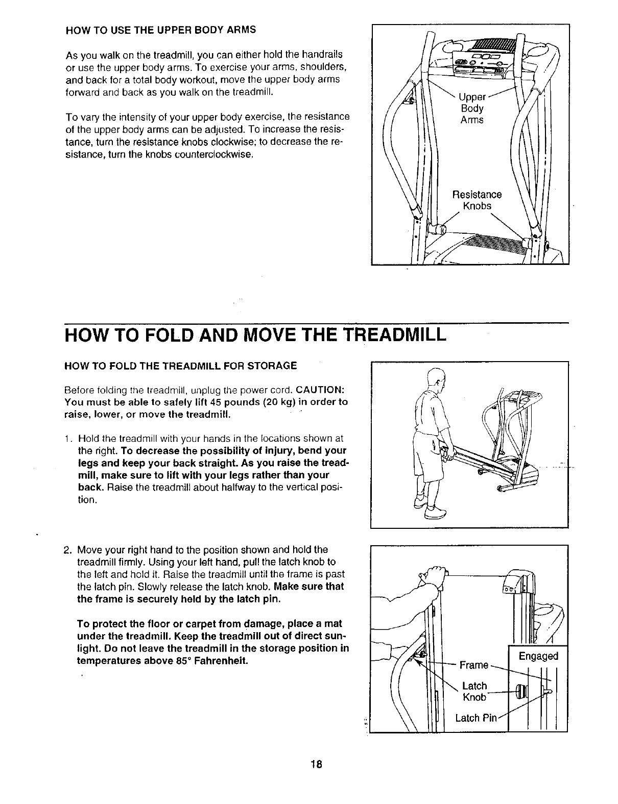
HOW TO USE THE UPPER BODY ARMS
As you walk on the treadmill, you can either hold the handrails
or use the upper body arms. To exercise your arms, shoulders,
and back for a total body workout, move the upper body arms
forward and back as you walk on the treadmill.
To vary the intensity of your upper body exercise, the resistance
of the upper body arms can be adjusted. To increase the resis-
tance, turn the resistance knobs clockwise; to decrease the re-
sistance, turn the knobs counterclockwise.
HOW TO FOLD AND MOVE THE TREADMILL
HOW TO FOLD THE TREADMILL FOR STORAGE
Before folding the treadmill, unplug the power cord. CAUTION:
You must be able to safely lift 45 pounds (20 kg) in order to
raise, lower, or move the treadmill.
1. Hold the treadmill with your hands in the locations shown at
the right. To decrease the possibi|ity of injury, bend your
legs and keep your back straight. As you raise the tread-
mill, make sure to lift with your legs rather than your
back. Raise the treadmill about halfway to the vertical posi-
tion.
2. Move your right hand to the position shown and hold the
treadmill firmly. Using your left hand, pull the latch knob to
the left and hold it. Raise the treadmill until the frame is past
the latch pin. Slowly release the latch knob. Make sure that
the frame is securely held by the latch pin.
To protect the floor or carpet from damage, place a mat
under the treadmill. Keep the treadmill out of direct sun-
light. Do not leave the treadmill in the storage position in
temperatures above 85° Fahrenheit. Frame
Latch
Knob--
Latch Pin/
Z.
Engaged
18
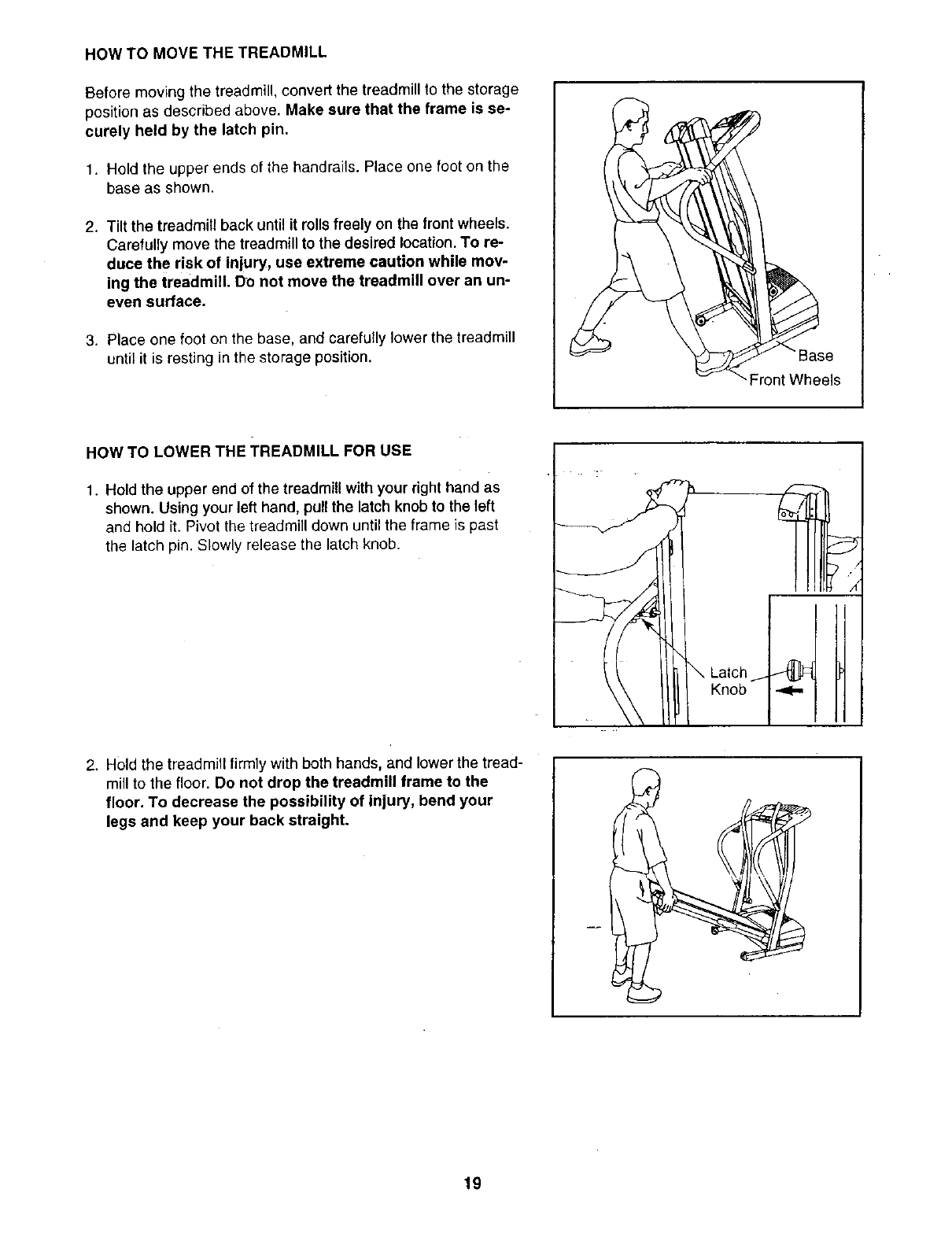
HOW TO MOVE THE TREADMILL
Before moving the treadmill, convert the treadmill to the storage
position as described above. Make sure that the frame is se-
curely held by the latch pin.
1. Hold the upper ends of the handrails. Place one foot on the
base as shown.
2. Tilt the treadmill back untilit rolls freely on the front wheels.
Carefully move the treadmill to the desired location. To re-
duce the risk of injury, use extreme caution while mov-
ing the treadmill, Do not move the treadmill over an un-
even surface.
3. Place one foot on the base, and carefully lower the treadmill
until it is resting in the storage position. e
"- Front Wheels
HOW TO LOWER THE TREADMILL FOR USE
1. Hold the upper end of the treadmill with your right hand as
shown. Using your left hand, pull the latch knob to the left
and hold it. Pivot the treadmill down until the frame is past
the latch pin. Slowly release the latch knob.
Knob
2. Hold the treadmill firmly with both hands, and lower the tread-
mill to the floor. Do not drop the treadmill frame to the
floor. To decrease the possibility of injury, bend your
legs and keep your back straight.
19
TROUBLESHOOTING
Most treadmill problems can be solved by following the simple steps below. Find the symptom that
applies, and follow the steps listed. If further assistance is needed, call toll-free 1-800-4-MY-HOME ®
(1-800-469-4663).
PROBLEM: The power does not turn on
SOLUTION: a. Make sure that the power cord is plugged into a surge suppressor, and that the surge suppressor
is plugged into a properly grounded outlet (see page 8). Use only a single-outlet surge suppressor
that meets all of the specifications described on page 8. Important: The treadmill is not compatible
with GFCI-equipped outlets.
b. After the power cord has been plugged in, make sure that the key is fully inserted into the console.
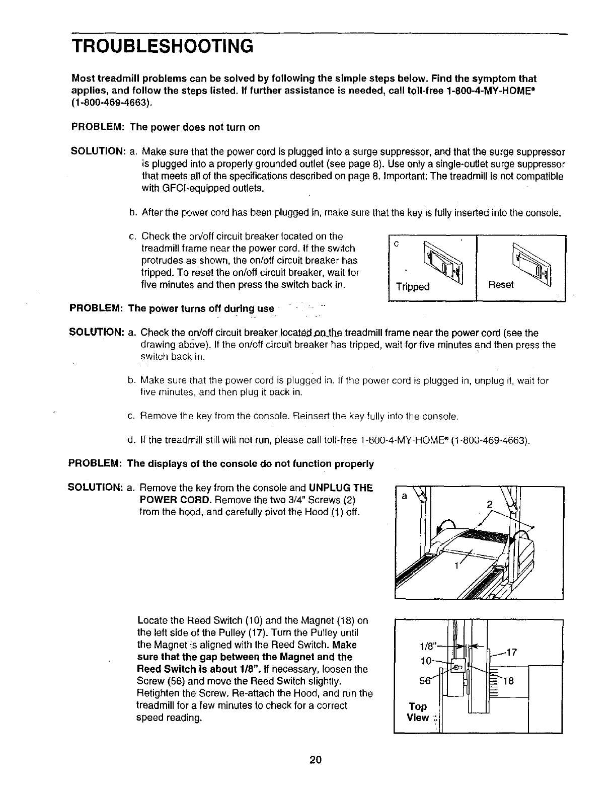
C, Check the on/off circuit breaker located on the
treadmill frame near the power cord, If the switch
protrudes as shown, the on/off circuit breaker has
tripped. To reset the on/oft circuit breaker, wait for
five minutes and then press the switch back in. Tripped
Reset%
PROBLEM: The power turns off during use "-
SOLUTION: a. Check the on/off circuit breaker located __the treadmill frame near the power cord (see the
drawing above). If the on/off circuit breaker has tripped, wait for five minutes and then press the
switch back in.
b. Make sure that the power cord is plugged in. if the power cord is plugged in, unplug it, wait for
five minutes, and then plug it back in.
c. Remove the key from the console. Reinsert the key fully into the console.
d. If the treadmill still will not run, please call toll-free 1-800-4-MY-HOME ®(1-800-469-4663).
PROBLEM: The displays of the console do not function properly
SOLUTION: a. Remove the key from the console and UNPLUG THE
POWER CORD. Remove the two 3/4" Screws (2)
from the hood, and carefully pivot the Hood (1) off.
Locate the Reed Switch (10) and the Magnet (18) on
the left side of the Pulley (17). Turn the Pulley until
the Magnet is aligned with the Reed Switch. Make
sure that the gap between the Magnet and the
Reed Switch is about 1/8". If necessary, loosen the
Screw (56) and move the Reed Switch slightly.
Retighten the Screw. Re-attach the Hood, and run the
treadmill for afew minutes to check for a correct
speed reading.
1/8"--
10_
To
View ',:11
]
20
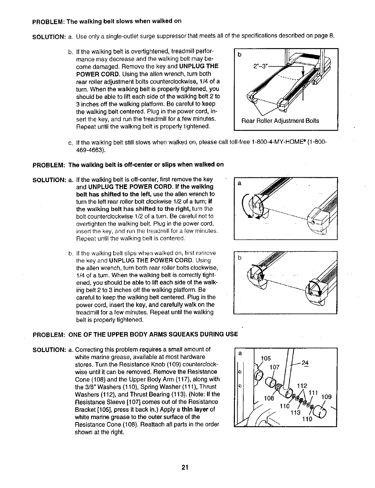
PROBLEM: The walking belt slows when walked on
SOLUTION: a. Use only a single-outlet surge suppressor that meets all of the specifications described on page 8.
b. If the walking belt is overtightened, treadmill perfor-
mance may decrease and the walking belt may be-
come damaged. Remove the key and UNPLUG THE
POWER CORD. Using the allen wrench, turn both
rear roller adjustment bolts counterclockwise, 1/4 of a
turn. When the walking belt is properly tightened, you
should be able to lift each side of the walking belt 2 to
3 inches off the walking platform. Be careful to keep
the walking belt centered. Plug in the power cord, in-
sert the key, and run the treadmill for a few minutes.
Repeat until the walking belt is properly tightened. Rear Roller Adjustment Bolts
c. If the walking belt still slows when walked on, please call toll-free 1-800-4-MY-HOME ®(1-800-
469-4663).
PROBLEM: The walking belt is off-center or slips when walked on
SOLUTION: a. If the walking belt is off-center, first remove the key
and UNPLUG THE POWER CORD. If the walking
belt has shifted to the left, use the allen wrench to
turn the left rear roller bolt clockwise 1/2 of a turn; if
the walking belt has shifted to the right, turn the
bolt counterclockwise 1/2 of a turn. Be careful not to
overtighten the walking belt. Plug in the power cord,
insert the key, and run the treadmill for a few minutes.
Repeat until the walking belt is centered.
b. If the walking belt slips when walked on, first remove
the key and UNPLUG THE POWER CORD. Using
the allen wrench, turn both rear roller botts clockwise,
1/4 of a turn. When the walking belt is correctly tight-
ened; you should be able to lift each side of the walk-
iiig belt 2 to 3 inches off the walking platform. Be
careful to keep the walking belt centered. Plug in the
power cord, insert the key, and carefully walk on the
treadmill for a few minutes. Repeat until the walking
belt is properly tightened.
PROBLEM: ONE OF THE UPPER BODY ARMS SQUEAKS DURING USE
SOLUTION: a. Correcting this problem requires a small amount of
white marine grease, available at most hardware
stores. Turn the Resistance Knob (109) counterclock-
wise until it can be removed. Remove the Resistance
Cone (108) and the Upper Body Arm (117), along with
the 3/8" Washers (110), Spring Washer (111), Thrust
Washers (112), and Thrust Bearing (113). (Note: If the
Resistance Sleeve [107] comes out of the Resistance
Bracket [105], press it back in.) Apply a thin layer of
white madne grease to the outer surface of the
Resistance Cone (108). Reattach all parts in the order
shown at the right.
e 24
IJ° E, y',oo
110 ._.
21
CONDITIONING GUIDELINES
The following guidelines will help you to plan your ex-
ercise program. For more detailed exercise informa-
tion, obtain a reputable book or consult your physician.
EXERCISE INTENSITY
Whether your goal is to burn fat or to strengthen your
cardiovascular system, the key to achieving the
desired results is to exercise with the proper intensity;
The proPer intensity level can be found by using your
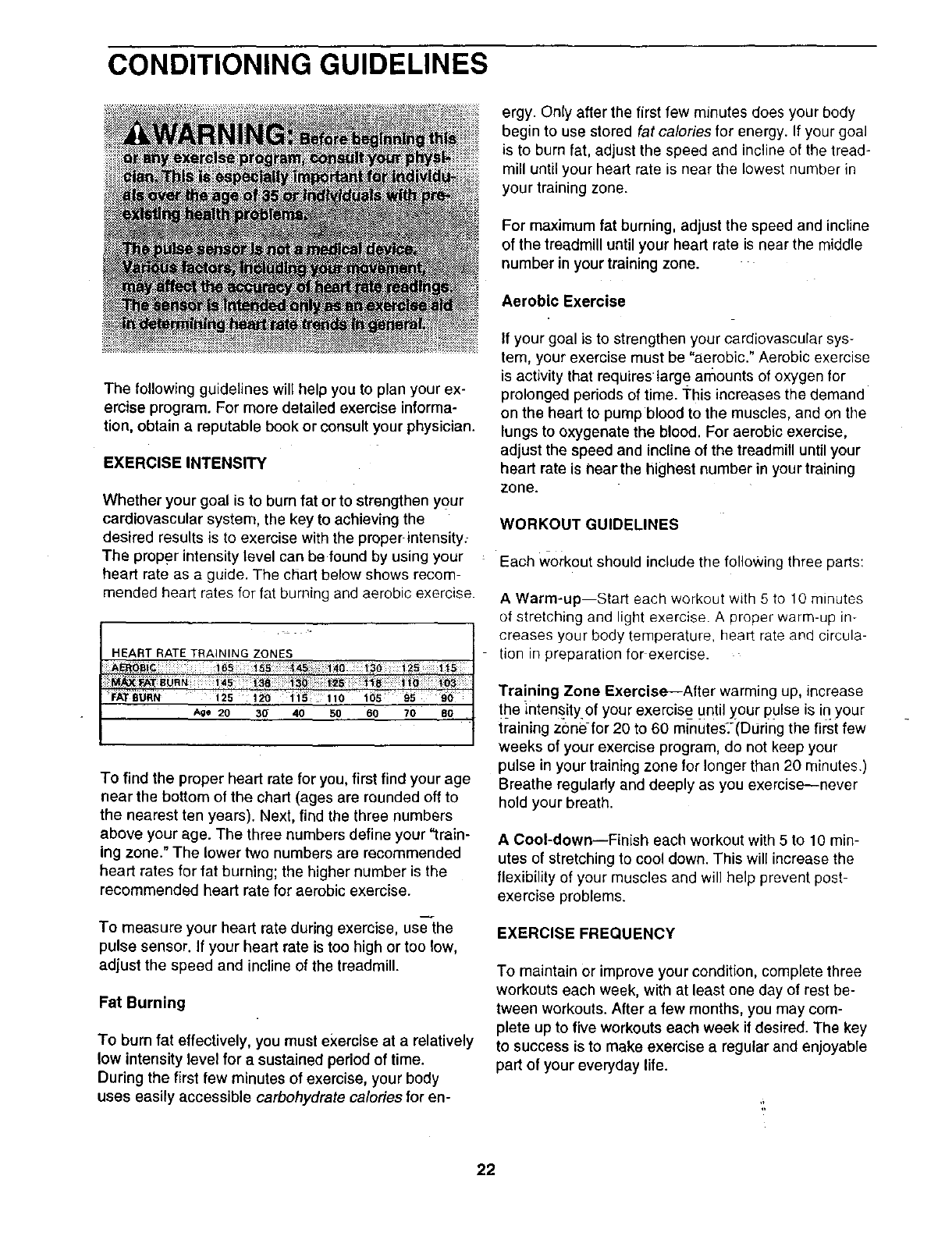
heart rate as a guide. The chart below shows recom-
mended heart rotes for fat burning and oerobic exercise.
Age 20
To find the proper heart rate for you, first find your age
near the bottom of the chart (ages are rounded off to
the nearest ten years). Next, find the three numbers
above your age. The three numbers define your "train-
ing zone." The lower two numbers are recommended
heart rates for fat burning; the higher number is the
recommended heart rate for aerobic exercise.
To measure your heart rate during exercise, use'_the
pulse sensor, if your heart rate is too high or too low,
adjust the speed and incline of the treadmill.
Fat Burning
To burn fat effectively, you must e_<erciseat arelatively
low intensity level for a sustained pedod of time.
During the first few minutes of exercise, your body
uses easily accessible carbohydrate calories for on-
ergy. Only after the first few minutes does your body
begin to use stored fat calories for energy. If your goal
is to burn fat, adjust the speed and incline of the treod-
mill until your heart rate is near the lowest number in
your training zone.
For maximum fat burning, adjust the speed and incline
of the treadmill until your heart rate is near the middle
number in your training zone.
Aerobic Exercise
if your goal is to strengthen your cardiovoscular sys-
tem, your exercise must be "aerobic." Aerobic exercise
is activity that requireslarge arnounts of oxygen for
prolonged periods of time. This increoses the demand
on the heart to pump blood to the muscles, and on the
lungs to oxygenate the blood. For aerobic exercise,
adjust the speed and incline of the treadmill until your
heart rate is nearthe highest number in your troining
zone.
WORKOUT GUIDELINES
Each workout should include the following three ports:
AWarm-up--Start eoch workout with 5 to 10 minutes
of stretching and light exercise. A proper warm-up in-
creoses your body temperature, heart rate and circula-
tion in preparation for exercise.
Training Zone Exercise--After warming up, increase
the inten§ity of your exercise until your pulse is irl your
training zone for 20 to 60 minutes_r(During the first few
weeks of your exercise program, do not keep your
pulse in your training zone for longer than 20 minutes.)
Breathe regularly and deeply as you exercise--never
hold your breath.
A Cool-down--Finish each workout with 5 to 10 min-
utes of stretching to cool down. This will increase the
flexibility of your muscles and will help prevent post-
exercise problems.
EXERCISE FREQUENCY
To maintain or improve your condition, complete three
workouts each week, with at least one day of rest be-
tween workouts. After a few months, you may com-
plete up to five workouts each week if desired. The key
to success is to make exercise a regular and enjoyable
part of your everyday life.
22
SUGGESTED STRETCHES
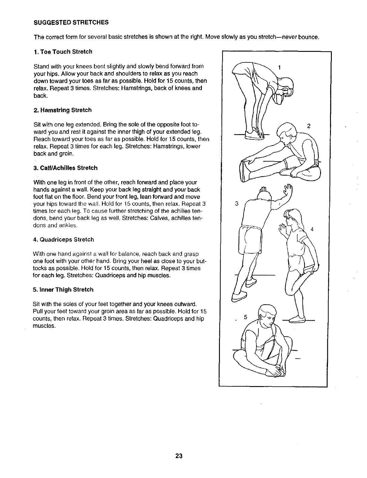
The correct form for several basic stretches is shown at the right. Move slowly as you stretch--never bounce.
1. Toe Touch Stretch
Stand with your knees bent slightly and slowly bend forward from
your hips. Allow your back and shoulders to relax as you reach
down toward your toes as far as possible. Hold for 15 counts, then
relax. Repeat 3 times. Stretches: Hamstrings, back of knees and
back.
2. Hamstring Stretch
Sit with one leg extended. Bring the sole of the opposite foot to-
ward you and rest it against the inner thigh of your extended leg.
Reach toward your toes as far as possible. Hold for 15 counts, then
relax, Repeat 3 times for each leg. Stretches: Hamstrings, lower
back and groin.
3. Calf/Achilles Stretch
With one leg in front of the other, reach forward and place your
hands against a wall. Keep your back leg straight and your back
foot flat on the floor. Bend your front leg, lean forward and move
your hips toward the wall. Hold for 15 counts, then relax. Repeat 3
times for each leg. To cause further stretching of the achilles ten-
dons, bend your back leg as well. Stretches: Calves, achilles ten-
dons and ankles.
4, Quadriceps Stretch
With one hand against a wall for balance, reach back and grasp
one foot with your other hand. Bring your heel as close to your but-
tocks as possible. Hold for 15 counts, then relax. Repeat 3 times
for each leg. Stretches: Quadriceps and hip muscles.
5. Inner Thigh Stretch
Sit with the soles of your feet together and your knees outward.
Pull your feet toward your groin area as far as possible. Hold for 15
counts, then relax. Repeat 3 times. Stretches: Quadriceps and hip
muscles.
2
23
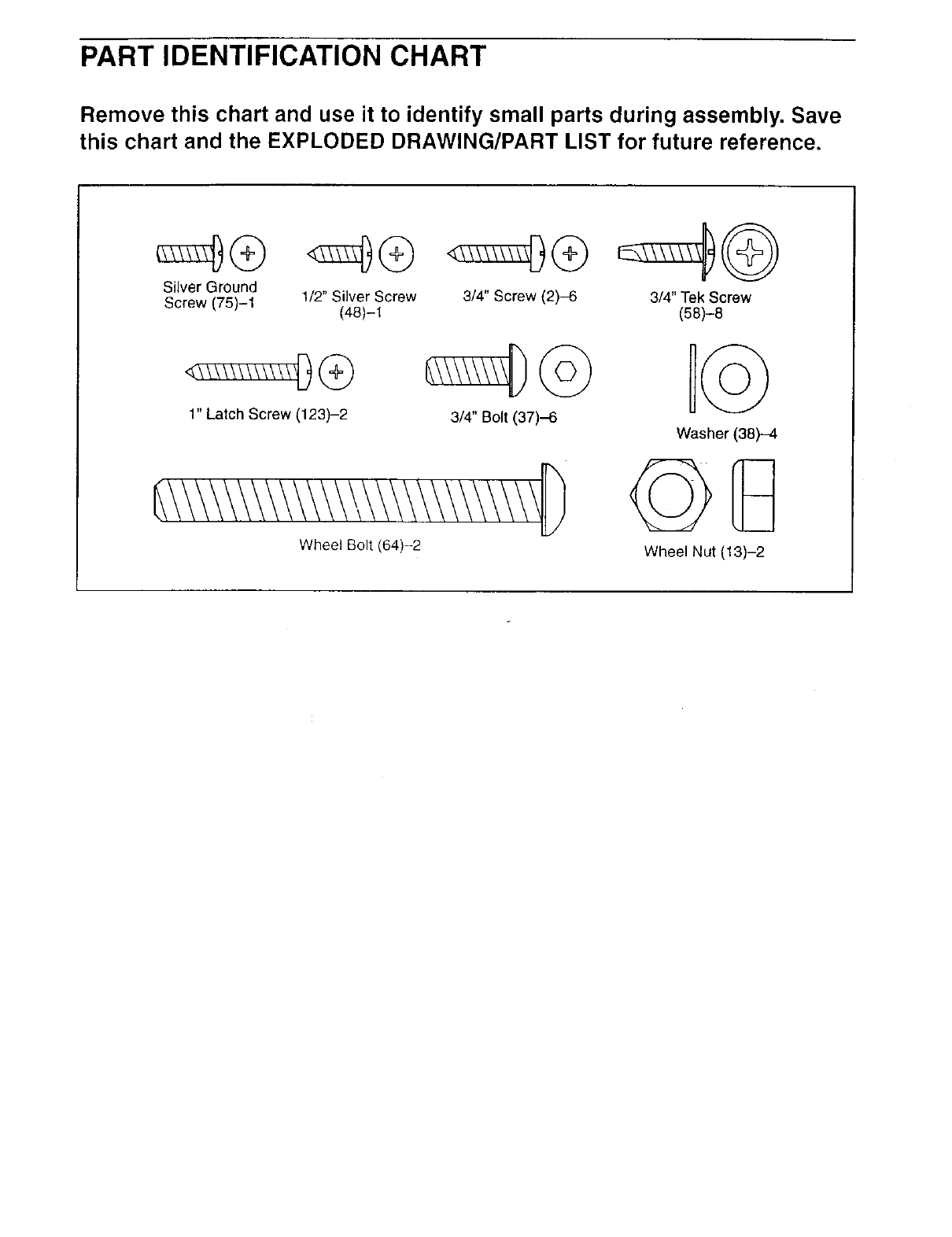
PART IDENTIFICATION CHART
Remove this chart and use it to identify small parts during assembly. Save
this chart and the EXPLODED DRAWING/PART LIST for future reference.
Silver Ground
Screw (75)-1 1/2" Silver Screw
(48)-1
1" Latch Screw (123)-2
3/4" Screw (2)-6
3/4" Bolt (37)-6
Wheel Bolt (64)-2
3/4" Tek Screw
(58)-8
Washer (38)-4
©G
Wheel Nut (13)-2
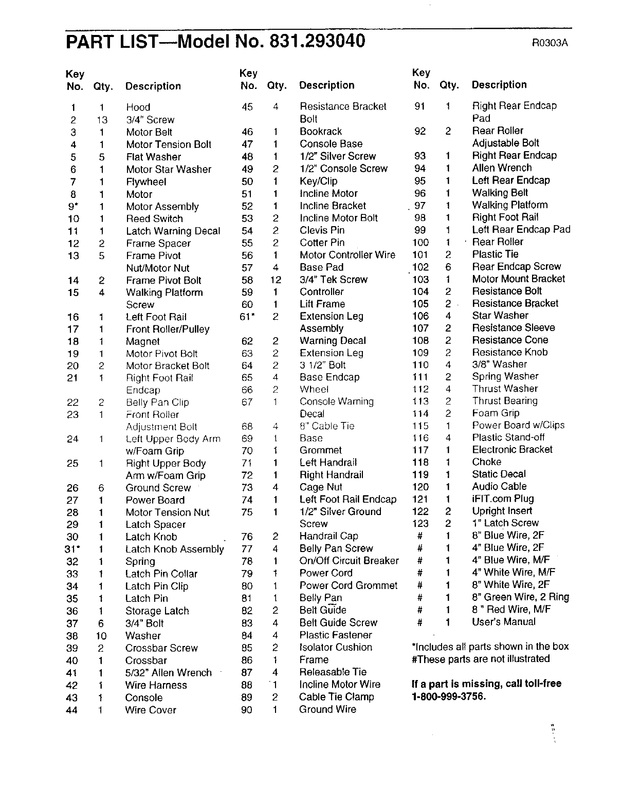
PART LIST--Model No. 831.293040 .03O3A
Key Key
No. Qty. Description No. Qty. Description
1 1 Hood 45 4 Resistance Bracket
2 13 3/4" Screw Bolt
3 1 Motor Belt 46 1 Bookrack
4 1 Motor Tension Bolt 47 1 Console Base
5 5 Flat Washer 48 1 1/2" Silver Screw
6 1 Motor Star Washer 49 2 1/2" Console Screw
7 1 Flywheel 50 1 Key/Clip
8 1 Motor 51 1 incline Motor
9* 1 Motor Assembly 52 1 Incline Bracket
10 1 Reed Switch 53 2 Incline Motor Bolt
11 1 Latch Warning Decal 54 2 Clevis Pin
12 2 Frame Spacer 55 2 Cotter Pin
13 5 Frame Pivot 56 1 Motor Controller Wire
NutJMotor Nut 57 4 Base Pad
14 2 Frame Pivot Bolt 58 12 3/4" Tek Screw
15 4 Walking Platform 59 1 Controller
Screw 60 1 Lift Frame
16 1 Left Foot Rail 61" 2 Extension Leg
17 1 Front Roller/Pulley Assembly
18 1 Magnet 62 2 Warning Decal
19 1 Motor Pivot Bolt 63 2 Extension Leg
20 2 Motor Bracket Bolt 64 2 3 1/2" Bolt
21 1 Right Foot Rail 65 4 Base Endcap
Endcap 66 2 Wheel
22 2 Belly Pan Clip 67 1 Console Warning
23 1 Front Rol}er Decal
Adjustment Bolt 68 4 8" Cable Tie
24 1 Left Upper Body Arm 69 1 Base
w/Foam Grip 70 1 Grommet
25 1 Right Upper Body 71 1 Left Handrail
Arm w/Foam Grip 72 1 Right Handrail
26 6 Ground Screw 73 4 Cage Nut
27 1 Power Board 74 1 Left Foot Rail Endcap
28 1 Motor Tension Nut 75 1 1/2" Silver Ground
29 1 Latch Spacer Screw
30 1 Latch Knob . 76 2 Handrail Cap
31" 1 Latch Knob Assembly 77 4 Belly Pan Screw
32 1 Spring 78 1 On/Off Circuit Breaker
33 1 Latch Pin Collar 79 1 Power Cord
34 1 Latch Pin Clip 80 1 Power Cord Grommet
35 1 Latch Pin 81 1 Belly Pan
36 t Storage Latch 82 2 Belt Guide
37 6 3/4" Bolt 83 4 Belt Guide Screw
38 10 Washer 84 4 Plastic Fastener
39 2 Crossbar Screw 85 2 Isolator Cushion
40 1 Crossbar 86 1 Frame
41 1 5/32" Allen Wrench 87 4 Releasable Tie
42 1 Wire Harness 88 1 Incline Motor Wire
43 1 Console 89 2 Cable Tie Clamp
44 1 Wire Cover 90 1 Ground Wire
Key
No, Qty. Description
91 1 Right Rear Endcap
Pad
92 2 Rear Roller
Adjustable Bolt
93 1 Right Rear Endcap
94 1 Allen Wrench
95 1 Left Rear Endcap
96 1 Walking Belt
• 97 1 Walking Platform
98 1 Right Foot Rail
99 1 Left Rear Endcap Pad
100 1 .Rear Roller
101 2 Plastic Tie
102 6 Rear Endcap Screw
103 1 Motor Mount Bracket
104 2 Resistance Bolt
105 2 Resistance Bracket
106 4 Star Washer
107 2 Resistance Sleeve
108 2 Resistance Cone
109 2 Resistance Knob
110 4 3/8" Washer
111 2 Spring Washer
112 4 Thrust Washer
113 2 Thrust Bearing
114 2 Foam Grip
115 1 Power Board w/Clips
116 4 Plastic Stand-off
117 1 Electronic Bracket
118 1 Choke
119 1 Static Decal
120 1 Audio Cable
121 1 iFIT.com Plug
122 2 Upright Insert
123 2 1" Latch Screw
# 1 8" Blue Wire, 2F
# 1 4" Blue Wire, 2F
# 1 4" Blue Wire, M/F
# 1 4" White Wire, M/F
# 1 8" White Wire, 2F
# 1 8" Green Wire, 2 Ring
# 1 8" Red Wire, M/F
# 1 User's Manual
*includes all parts shown in the box
#These parts are not illustrated
If a part is missing, call toll-free
1-800-999-3756.
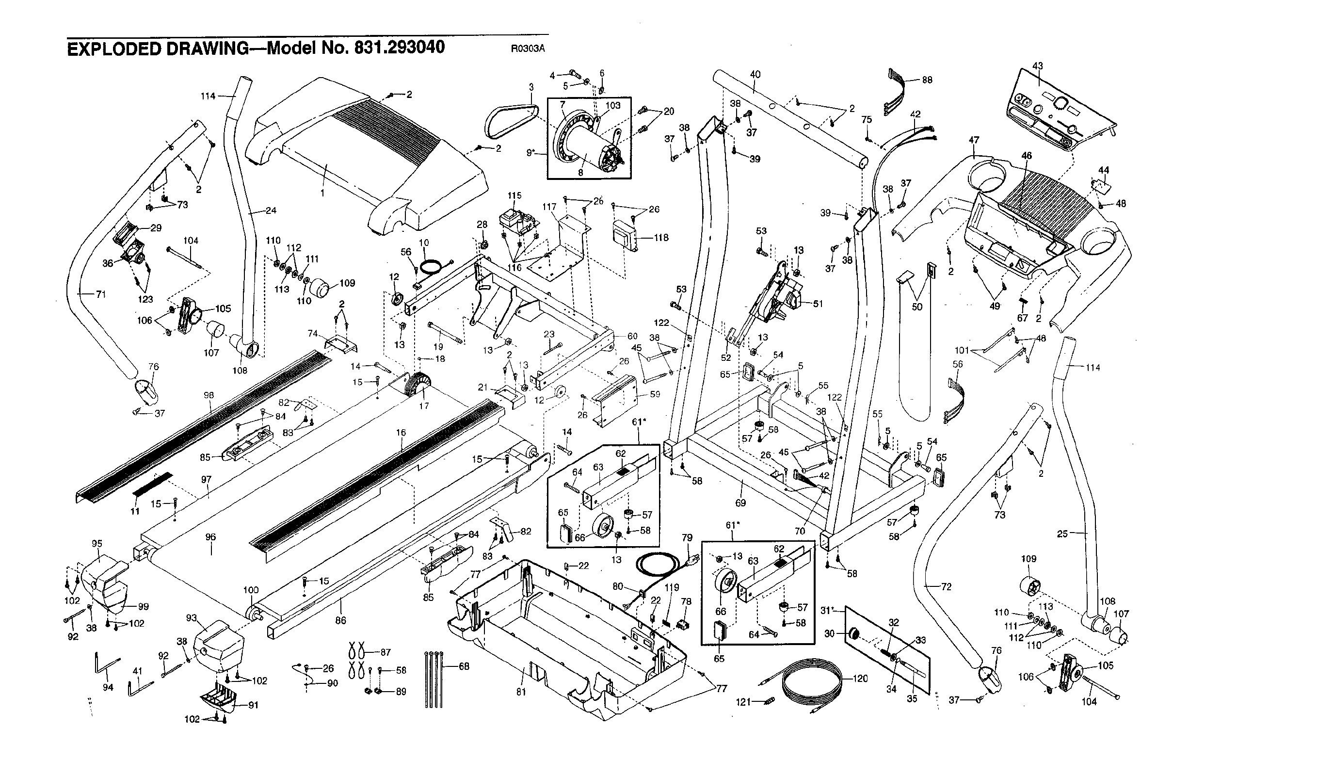
EXPLODED DRAWING---Model No. 831.293040 RO303A
r2
72O
38
37
4O
37
L-_39
115
117
16 I
I 14
_-26
,_118 53,
_.i , 13
• !
'---. _ 37
53
122.
145 38
26 4 5
26 61"
62 !57
_42 88
,5 54
102
92
11
95
41
97
96
I
38
92
102_LJ
100 85
81
80_ 119
47
49
101_
56
73
76
43
46 :
,, 44
109
'," 1t3 "',-.
112_
,, -..-

•.:i!.¸
Your Home
For repair - in your home - of all major brand appliances, lawn and garden equipment,
or heating and cooling systems, no matter who made it, no matter who sold it!
For the replacement parts, accessories, and user's manuals that you need to do-it-yourself.
For Sears professional installation of home appliances
and items like garage door openers and water heaters.
1-800-4.MY-HOM E®Anytime, day o_ n ght
(1-800-469-4663) (U.S.A. and Canada)
www.sears°com www, seara.ca
Our Home
For repair of carry-in products like vacuums, lawn equipment,
and electronics, call or go on-line for the location of your nearest
Sears Parts and Repair Center.
1-800-488-1222 An_ime, day or night (U.S.A. only)
www.sears.com
g_
N
:::::
:.:.x:::.:
::>x:::
_ To purchase a protection agreement (U S A )
_,_;_ or maintenance agreement (Canada) on aproduct serviced by Sears:
:_,:.:::_"_":................ 1....800 827 6655 (us__). 1 800-361 -6665 (Canada)
:,.,:.:........... Para pedir servicio de reparacidn a domicilio, y para ordenar piezas:
,,__:_ 1-888-SU HOGAR (1-888-784..6427)
® Registered Trademark /mTrademark /su Service Mark of Sears, Roebuck and Co.
® Mama Registrada /"ruMarca de F_bdca /s_ Mama de Servicio de Sea_, Roebuck and Co.
f
FULL 90 DAY WARRANTY
For 90 days from the date of purchase, if failure occurs due-tb defect in material or workmanship in this
Sears Treadmill Exerciser, contact the nearest Sears Service Center throughout the United States and
Sears will repair or replace the Treadmill Exerciser, free of charge.
This warranty does not apply when the Treadmill Exerciser is used commercially or for rental purposes.
This warranty gives you specific legal rights, and you may also have other rights which vary from state to
state.
Sears, Roebuck and Co., Dept• 817WA, Hoffman Estates, IL 60179
J,,
Part No. 189308 R0303A Printed in USA © 2003 Sears, Roebuck and Co.
