Proform 831294060 User Manual 585S Manuals And Guides L0402002
PROFORM Treadmill Manual L0402002 PROFORM Treadmill Owner's Manual, PROFORM Treadmill installation guides
User Manual: Proform 831294060 831294060 PROFORM PROFORM 585S - Manuals and Guides View the owners manual for your PROFORM PROFORM 585S #831294060. Home:Fitness Equipment Parts:Proform Parts:Proform PROFORM 585S Manual
Open the PDF directly: View PDF ![]() .
.
Page Count: 30
r-_r_C_-FC:_rq_/ta __
IN a,---_,_l:::lr'-TIVl=" TI:_t:::IINI='I:_
Model No. 831.294060
Serial No.
Serial Number Decal
• Assembly
•Operation
•Maintenance
•Part List and Drawing
TREADMILL EXERCISER
User's Manual
Sears, Roebuck and Co, Hoffman Estates, IL 60179

TABLE OF CONTENTS
IMPORTANT PRECAUTIONS ................................................................ 2
BEFORE YOU BEGIN ...................................................................... 4
ASSEMBLY ............................................................................... 5
OPERATION AND ADJUSTMENT ............................................................. 8
HOW TO FOLD AND MOVE THE TREADMILL .................................................. 21
TROUBLESHOOTING ..................................................................... 22
CONDITIONING GUIDELINES ............................................................... 24
PART LIST .............................................................................. 26
PART IDENTIFICATION CHART ............................................................. 27
ORDERING REPLACEMENT PARTS .................................................. Back Cover
FULL ONE YEAR WARRANTY ....................................................... Back Cover
Note: An EXPLODED DRAWING is attached in the center of this manual.
IMPORTANT PRECAUTIONS
products are used or where oxygen is being
adn'dnistsrsd.
6. Keep children u_the age of 12 and bets
away from the treadmill =all times.
7. The treadmill should be used only by persons
weighing 250 pounds or less.
8. Never allow more than one person on the ................
2

product.
The decals shown have been placed on your treadmill. If a
decal is missing, or if it is not legible, please call toll-free
1-800-999-3756 to order a free replacement decal. Apply the
decal in the location shown. Note: The decals are not
shown at actual size.
3
ACA ON
KEEPHANDSAND FEETAWAY
FROMTHISAREAWHILETHE
TREADMILLISINOPERATION.
P,ote_l y_Jr,_l ar_
oll'_s Irom rrsk c__r_cL_
ir_u{y_ Read _e user_
manual and
BEFORE YOU BEGIN
Thank you for selectingthe revolutionaryPROFORM®
585s treadmill.The 585s treadmill combinesadvanced
technologywith innovativedesignto help you get the
most fromyour exerciseprogram inthe convenience
and privacyof your home. And when you'renot exer-
cising,the unique 586s treadmillcan be folded up, re-
quiringless than half the floorspace of other treadmills.
For your benefit, read this manual carefully before
using the treadmill. If you have questionsafter read-
ing thismanual, call 1-800-4-MY-HOME ®(1-800-469-
4663).To help us assist you, please note the product
model numberand serial number before calling.The
model numberof the treadmill is 831.294060. The ser-
ial number can be foundon a decal attached to the
treadmill (see the front cover of this manual for the lo-
cation).
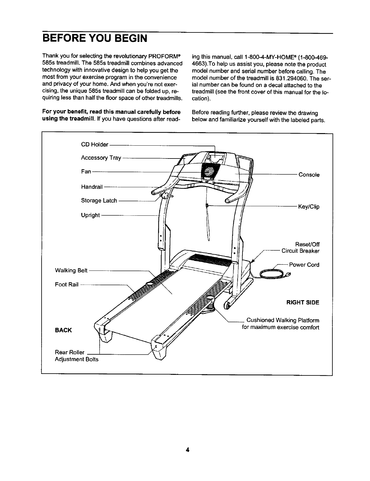
Before reading further, please review the drawing
below and familiarize yourselfwiththe labeled parts.
CD Holder
Accessory Tray
Fan
Handrail
Storage Latch
Upright
Console
Key/Clip
Walking Belt
Foot Rail
Reset/Off
Breaker
RIGHT SIDE
BACK
Cushioned Walking Platform
for maximum exercise comfort
Rear Roller
Adjustment Bolts
4

ASSEMBLY
Assembly requires two persons. Set the treadmill ina cleared area and remove all packingmaterials. Do not
disposeof the packingmaterialsuntilassemblyis completed. Note: The undersideof the treadmillwalkingbelt is
coated with high-performancelubricant.During shipping,a small amount of lubricantmay be transferredto the
top of the walking belt or the shippingcarton.This is a normalconditionand does notaffect treadmill perfor-
mance. If there is lubricanton top of the walking belt, simplywipe off the lubricantwitha sot_cloth and a mild,
non-abrasivecleaner.
Assembly requires the included allen wre_ and your own phillips screwdriver
and wire cutters _.
1. Make sure that the power cord is unplugged.
To identify small parts, use the PART IDENTIFICA-
TION CHART on page 27. Note: If a partis not inthe
parts bag, check to see if it has been pre-assembled. If
a part is missing, call toll-free 1-800-999-3756.
With the help of a second person, carefullyraise the
Upright Base (97) to the positionshown. Insert one of
the ExtensionLegs (92) into the UprightBase. (Note: It
may be helpfulto tipthe UprightBase forward as you in-
sert the ExtensionLeg.) Make sure that the Warning
Decal (91) is in the locationshown.
Insert the otherExtension Leg (notshown) inthe same
way.
97
92
2. With the help of a second person, carefully tip the
Upright Base (97) down as shown. (Note: It may be help-
ful to place your foot on one of the Extension Legs [92]
as you tip the Uprights.) Make sure that the Extension
Legs remain in the Uprights.
Attach each Extension Leg (92) with two Extension Leg
Bolts (96) and two 114"Washers (39) as shown. Thread
a Leveling Foot (95) into each side of the Upright Base
(97); do not thread the Leveling Feet fully into the
Upright Base.
Attach the two Base Pads (99) to the UprightBase (97)
in the locations shown with two 1" Tek Screws (40).
With the help of a second person, raise the Upright Base
(97) to the vertical position.
96
95
92"_ _
5

3. Attach the Latch Assembly (82) to the Left Upright (84)
with the two Latch Screws (46). Start both Latch Screws
before tightening either of them. Note: The Latch Screws
may be preattached to the Left Upright.
46 82
4. Refer to step 6 and locate the four Upright Bolts (86).
Loosen the Upright Bolts two to three turns.
Refer to drawing 4c. With the help of a second person,
hold the Console Base (101) near the Uprights (80, 84).
Look under the Console Base and locate the wires on
the sides of the Console Base. Make sure that the wires
are not routed through the openings for the Trays (109,
111). Drawing 4a shows the correct route for the wires.
Drawing 4b shows an incorrect route.
Refer to drawing 4c. Cut the plastic ties holding the Wire
Harness (74) and the Pulse Wire in the Uprights (80, 84).
Connect the Wire Harness and the Pulse Wire to the
wires on the sides of the Console Base (101). Make sure
to connect the connectors properly (see the inset
drawings). IF THE CONNECTORS ARE NOT CON-
NECTED PROPERLY, THE CONSOLE MAY BE DAM-
AGED WHEN THE POWER IS TURNED ON. The con-
nectors should slide together easily and snap into
place. If the connectors do not slide together easily and
snap into place, turn one connector and try again. Insert
the excess Wire Harness and Pulse Wire up into the
Console Base.
Press the Right and Left Top Endcaps (75, 81) into the
Uprights (80, 84) as shown.
4a
Correct %
Incorrect
4c
5. Set the Console Base (101) on the Uprights (80, 84). Be
careful not to pinch the Wires (not shown) in the
Uprights. Attach the Console Base to each Upright with
two Console Bolts (76) and two Internal Star Washers
(77); start all four Console Bolts before tightening any of
them.
Make sure that the Left and Right Trays (109, 111) are
pressed into the Console Base (101).
6
5101
>77 77-_ _
_80 76 /

6. If the Wheels (not shown) are touchingthe floor, or if the
treadmill rocks slightly, see HOW TO LEVEL THE
TREADMILL on page 20.
If you wish to adjust the height of the Uprights (80,
84), go to step 7. If the Uprights are at the desired
height, tightenthe four UprightBolts(86) and go to step 8.
7. Note: The Uprights (80, 84) can be attached at three dif-
ferent heights. The Uprights are preattached in the mid-
dle position. Adjusting the Uprights requires two persons.
While a second person holds the Console Base (101) and
the Uprights (80, 84), loosen the four Upright Bolts (86).
Then, remove the two Upright Bolts and Upright Star
Washers (127) from the Right Upright (80). Raise or lower
the Right Upright to the desired height, being careful not
to damage the Wire Harness (74). If the Upright Spacer
(79) falls, press it back onto the Upright Base (97).
Loosely thread the two Upright Bolts and Upright Star
Washers back intothe Right Upright and the Upright Base.
Adjust the Left Upright (84) in the same way. (Note: There
are no wires in the Left Upright.) Make sure that both
Uprights are at the same height. Lift the Walking
Platform (13) and make sure it is centered between
the Uprights. Retighten all four Upright Bolts (86).
8. Make sure that all parts are properly tightened before you use the treadmill. Note: Extra hardware may
be included. Keep the included allen wrenches in a secure place. The large allen wrench is used to adjust the
walking belt (see page 23). To protect the floor or carpet, place a mat under the treadmill.
If you purchase the optional chest pulse sensor (see
page 20), follow the steps below to install the receiver
included with the chest pulse sensor.
1. Make sure that the power cord is unplugged. Remove
the indicated Screw (108) and the Access Door (122).
2. Remove the paper from the adhesive pad on the back of
the receiver (A). Orient the receiver so the small cylin-
der is near the lower edge of the receiver and is fac-
ing the Console (107) as shown. Firmly press the re-
ceiver onto the indicated corner of the Access Door
(122). Connect the wire on the receiver to the indicated
wire extending from the Console.
3. Make sure that no wires are pinched. Reattach the
Access Door (122) with the Screw (108), Note: The wires
included with the receiver may be discarded.
107
Wire

OPERATION AND ADJUSTMENT
THE PERFORMANT LUBE TM WALKING BELT
Your treadmill features a walking belt coated with
PERFORMANT LUBE TM, a high-performance lubricant.
IMPORTANT: Never apply silicone spray or other
substances to the walking belt or the walking plat-
form, Such substances will deteriorate the walking
belt and cause excessive wear.
HOW TO PLUG IN THE POWER CORD
an equipment-grounding conductorand a grounding
plug. Plug the power cord into a surge suppressor,
and plug the surge suppressor into an appropriate
outlet that is properly installed and grounded in
accordance with all local codes and ordinances,
Important: The treadmill is not compatible with
GFCl-equipped outlets,
This product is for use on a nominal 120-voltcircuit,
and has a grounding plug that looks like the plug illus-
trated in drawing 1 below. A temporary adapter that
looks like the adapter illustrated in drawing 2 may be
used to connect the surge suppressor to a 2-pole
receptacle as shown in drawing 2 if a properly
grounded outlet is not available.
Your treadmill, like any other type of sophisticated
electronic equipment, can be seriously damaged by
sudden voltage changes in your home's power.
Voltage surges, spikes, and noise interference can
result from weather conditions or from other appliances
being turned on or off. To decrease the possibility of
your treadmill being damaged, always use a surge
suppressor with your treadmill (see drawing 1 at
the right). To purchase a surge suppressor, see
your local Sears or call 1-800-366-7278 and order
part number 146148.
Use only a single-outlet surge suppressor that is
UL 1449 listed as a transient voltage surge sup-
pressor (TVSS). The surge suppressor must have a
UL suppressed voltage rating of 400 volts or less
and a minimum surge dissipation of 450 joules.
The surge suppressor must be electrically rated
for 120 volts AC and 15 amps. There must be a
monitoring light on the surge suppressor to indi-
cate whether it is functioning properly. Failure to
use a properly functioning surge suppressor could
result in damage to the control system of the
treadmill. If the control system is damaged, the
walking belt may change speed or stop unexpect-
edly, which may result in a fall and serious injury.
This product must be grounded. If it should malfunc-
tion or break down, grounding provides a path of least
resistance for electric current to reduce the risk of elec-
tric shock. This product is equipped with acord having
2
Grounded Outlet Box
_'-1 _¢_'_ Surge SuppressOr
'_.. Grounding Pin
Grounding Pin
Grounded Outlet Grounding Plug
Grounded Outlet Box
Adapter
_1_,.--_ Surge Suppressor
The temporary adapter should be usedonly until a
properly grounded outlet (drawing 1) can be installed
by a qualified electrician.
The green-colored rigid ear, lug, or the like extending
from the adapter must be connected to a permanent
ground such as a properly grounded outlet box cover.
Whenever the adapter is used it must be held in place
by a metal screw. Some 2-pole receptacle outlet box
covers are not grounded. Contact a qualified elec-
trician to determine if the outlet box cover is
grounded before using an adapter.
8

Note: If there are thin sheets of clear
plastic on the console, remove them. Key
FEATURES OF THE CONSOLE
The treadmill console offers an impressive array of
features that help you get the most from your workouts.
When the manual mode of the console is selected, the
speed and incline of the treadmill can be changed with
the touch of a button. As you exercise, the console will
display instant exercise feedback. You can even mea-
sure your heart rate using the handgrip pulse sensor or
the optional chest pulse sensor (see page 20).
In addition, the console offers six preset workout pro-
grams. Each program automatically controls the speed
and incline of the treadmill as it guides you through an
effective workout. Two pulse programs are also offered.
Each program automatically adjusts the speed and in-
cline of the treadmill to keep your heart rate within a tar-
get range while you exercise.
The console also features iFIT.com interactive technol-
ogy. Having iFIT.com technology is like having a per-
sonal trainer inyour home. Using the included audio
cable, you can connect the treadmill to your home
stereo, portable stereo, or computer and play special
iFIT.com CD and video programs (one iFIT.com CD is
included; additional CDs and videocassettes are avail-
able separately), iFIT.com CD and video programs au-
tomatically control the speed and incline of the treadmill
as a personal trainer guides you through every step of
your workout. High-energy music provides added moti-
vation. To purchase iFIT,com CDs or videocas-
settes, call toll-free 1-800-735-0768.
With the treadmill connected to your computer, you
can also go to our Web site at _.iFIT.com and ac-
cess programs directly from the intemet. Additional op-
tions are soon to be available. See www.iFIT.com for
more information.
To use the manual mode of the console, followthe
steps beginning on page 10. To use preset programs,
see page 12. To use heart rate programs, see page
13. To use an iFIT.com CD or video program, see
page 17. To use iFIT.com programs directly from
our Web site, see page 19.
9

_lPlug inthe power cord (see page 8).
B Locate the reset/off
circuit breaker near
the power cord. Make
sure that the circuit
breaker is in the reset
position.
Reset
Position
laStand on the foot rails of the treadmill.Find the clip
attachedto the key (see the drawing onpage 9)
and slidethe clip ontothe waistbandof your
clothes.Next, routethe cord attachedto the clip
under the handgrip pulse sensor, and insertthe
key into the console.After a moment, the displays
and variousindicatorswill light. Test the clip by
carefully taking a few steps backward until the
key is pulled from the console. If the key is not
pulled from the console, adjust the position of
the clip.
HOWTO USE THE MANUAL MODE
BInsert the key fully into the console.
See HOW TO TURN ON THE POWER above.
B Select the manual mode.
When the key is in-
serted, the manual
mode will be selected.
To reselectthe manual
mode, pressthe
Program Select button
repeatedly untila track
appears in the matrix. Make surethat the indicator
on the iFIT.com button is not lit.
0@@@@@@01
0@000000@0
@00000000@
@00000000@
@00000000@
0@000000@0
0@@@@@@0
1_1 Press the Start button or the Speed Abutton to
start the walking belt.
Amoment after the button is pressed, the walking
belt will begin to move at Imph. Hold the handrails
and begin walking.
As you exercise, change the speed of the walking
belt as desired by pressing the Speed V and A
bu onsEachtmearlcoo1
button is pressed, the I I I- I
speed settingwill --I. _-'_
change by 0.1 mph; if a o ....
button is held down, the
speed setting will
change in increments of 0.5 mph. To change the
speed setting quickly, press the Quick Speed but-
tons, Note: The console can display speed and
distance in either miles or kilometers. For sim-
plicity, all instructions in this section refer to
miles.
To stop the walkingbelt, press the Stop button.
The Time/Pace display will begin to flash. To
restart the walking belt, press the Start button or
the Speed A button.
Note: The first time the treadmill is used,observe
the alignment of the walkingbelt,and alignthe
walkingbeltif necessary (see page 23).
B Change the incline of the treadmill as desired.
To change the inclineof
the treadmill, press the
Incline V and A buttons.
Each time a button is
pressed, the incline will
change by 0.5%.
DISTRNE_
/
• INCLINE
in ......
B Follow your progress with the matrix and the
displays.
The matrix--When the
manual mode orthe
iFIT.com mode is se-
lected, the matrixwill
displaya 1/4-mile track.
As youexercise, the in-
dicatorsaroundthe track
0011110101
0100000010
1000000001
1000000001
0000000001
0000000010
00000@@@0.
will light, one at a time, until the entire track is lit.
The track will then darken and begin to light again.
Speed display--This II 1
of the walking belt. Note:
When the KM/H indica- _L_ -I. _/I
tor is lit, the console will o
display speed and dis-
tance in kilometers; when the KM/H indicator is
not lit, the console will display speed and distance
in miles.
10

Tochan0etheunit°r
measurement, firsthold _EEO ,_o.
down the Stop button i--
white inserting the key o ....
into the console. An "E"
for English miles or an
"M" for metric kilometerswill appear in the Speed
display. Press the Speed/k button to change the
unit of measurement. When the desired unit of
measurement is selected, remove the key.
Calories/Pulse [ "_
display--This display II I-! ._ll
shows the approximate !LI I__J
numbers of calories and O r"F_" CAL_
fat calories you have o _
burned (see FAT BURN-
ING on page 24). The
display will change from one number to the other
every few seconds. The display will also show
your heart rate when you use the handgdp pulse
sensor or the optional chest pulse sensor.
Distance/Incline dis-
play--This display
shows the distance that
you have walked or run
and the incline level of
the treadmill. The display
O INCLINE
l/ ......
will change from one number to the other every
few seconds. Note: Each time the incline changes,
the display will show the incline setting for several
seconds.
Time/Pace display--
When the manual mode
or the iFIT.com mode is
selected, thisdisplaywill
show the elapsed time
and your currentpace
(pace is measured in minutesper mile). The dis-
play will change from one number to the other
every few seconds.When a presetprogram or a
heart rate program is selected, the display will
show the time remaining in the program rather
than the elapsed time.
TIM_
I-,,,,-F_,j
LJ-7.-i
r_ Measure your heart rate if desired.
You can measure your heart rate using either the
handgdppulse sensor or the optionalchest pulse
sensor.
To reset the displays, press the Stop button, re-
move the key, and then reinsert the key.
To use the hand-
grip pulse sen-
sor, first make
sure that your
hands are clean.
Next, stand on
the foot rails
and holdthe
handgrippulse
sensor with your palms resting on the metal con-
tacts, Avoid moving your hands. When your
pulse is detected, two dashes (- -) will appear in
the Calories/Pulse display, and then your heart
rate will be shown. For the most accurate heart
rate reading, continue to hold the contacts for
about 15 seconds.
I[] Turn on the fan if desired.
To turn on the fan, pressthe buttonbelow the fan,
To turn on the fan at highspeed, pressthe button
a second time, To turn off the fan, pressthe but-
tona thirdtime, Note:A few minutes after the
walking belt is stopped, the fan will automatically
turn off.
r_ When you are finished exercising, remove the
key from the console.
Step onto the foot rails, press the Stop button, and
adjust the incline of the treadmill to the lowest
setting. The incline must be at the lowest setting
when the treadmill is folded to the storage posi-
tion or the treadmill will be damaged, Next, re-
move the key from the console and put it in a se-
cure place. Note: If the displays and various indi-
cators on the console remain lit after the key is
removed, the console is in the "demo" mode.
See page 20 and turn off the demo mode.
When you are finished usingthe treadmill,move
the reset/off circuit breaker switch near the power
cord to the off position and unplug the power cord.
11

HOW TO USE PRESET PROGRAMS
_! Insert the key fully into the console.
See HOW TO TURN ON THE POWER on page
10.
BSelect one of the preset programs.
When the key
is inserted, the
manual mode
will be se-
lected. To se-
lect a preset
program,
press the Program Select button repeatedly until
one of the six preset program indicators lights.
When a preset program is selected, the Speed
display will flash the maximum speed setting of
the program, and the Distance/Incline display will
flash the maximum incline setting, for six seconds.
The Time/Pace display will show how _ongthe
program will last.
The matrix will show
the first seven speed
settings of the program.
Note: The profiles
below the matrix show
how the speed and in-
cline of the treadmill
3000000000
3000000000
3000OO00QO
_O00000QO0
OOOOQSQQte
will change during the programs.
[_1 Press the Start button orthe Speed _button to
start the program.
A moment after the button is pressed, the tread-
mill will automatically adjust to the first speed and
incline settings of the program. Hold the handrails
and begin walking.
Each program is divided into several time seg-
ments of different lengths. One speed setting and
one incline setting are programmed for each seg-
ment. Note: The same speed setting and/or in-
cline setting may be programmed for consecutive
segments.
The speed setting for the
first segment is shown in
the flashing Current
Segment column of the
matrix. (The incline set-
tings are not shown in
the matrix.) The speed
settings for the next
seven segments are
Cur_nt Segment
_°°°°°° I
0000000
O000Q00
OOQQOQO
0000000
0000000
QQQtIQ
shown in the seven columns to the right.
When only three seconds remain inthe first seg-
ment of the program, both the Current Segment
column and the column to the right will flash and a
series of tones will sound. In addition, if the speed
and/or incline of the treadmill is about to change,
the Speed display and/or the Distance/Incline dis-
play willflash to alert you. When the first segment
is completed, all speed settings will move one col-
umn to the left. The speed setting for the second
segment will then be shown in the flashing Current
Segment column and the treadmill will automati-
cally adjust to the speed and incline settings for
the second segment. Note: If all of the indicators in
the Current Segment column are lit after the speed
settings have moved to the left, the speed settings
will move downward so that only the highest indi-
cators appear in the matrix. If some of the indica-
tors in the Current Segment column are not lit
when the speed settings move to the left again, the
speed settings will move back up.
The program will continue in this way until the
speed setting for the last segment is shown in the
Current Segment column of the matrix and the
Time/Pace display counts down to zero. The walk-
ing belt will then slow to a stop.
If the speed or incline setting is too high or too low
at any time during the program, you can manually
override the setting by pressing the Speed or
Incline buttons. Every few times a Speed button is
pressed,an additional indicatorwill light or darken
in the Current Segment column. (If any of the
columns to the right of the Current Segment col-
umn have the same number of lit indicators as the
Current Segment column, an additional indicator
may light or darken in those columns as well.)
Note: When the next segment of the program
begins, the treadmill will automatically adjust
to the speed and incline settings for the next
segment.
12

To stop the program temporarily, press the Stop
button. The Time/Pace display will begin to flash.
To restart the program,press the Start button or
the Speed/k button. To end the program, press
the Stop button, remove the key, and then reinsert
the key.
B Follow your progress with the displays.
See step 5 on page 10.
[]Measure your heart rate if desired.
See step 6 on page 11.
r_Turn on the fan if desired.
See step 7 on page 11.
B When the program is finished, remove the key
from the console.
When the program has ended, make sure that
the incline of the treadmill is at the lowest set-
ting, Next, remove the key fromthe consoleand
put it in a safe place. Note: If the displays and
various indicators on the console remain lit
after the key Is removed, the console is in the
"demo" mode. Refer to page 20 and turn off the
demo mode.
When you are finishedusing the treadmill, move
the reset/off circuit breaker switch near the power
cord to the off position and unplug the power cord.
HOW TO USE HEART RATE PROGRAMS
Follow the steps below to use a heart rate program.
Note: You must wear the optional chest pulse sen-
sor (see page 20) to use a heart rate program.
B Put on the chest pulse sensor.
See the instructions included with the optional
chest pulse sensor.
B Insert the key fully into the console.
See HOW TO TURN ON THE POWER on page
10.
B Select a heart rate program.
When the key
is inserted, the
manual mode
will be se-
lected. To se-
lect aheart
rate program,
press the Program Select button repeatedly until
one of the two heart rate program indicators lights.
The two profiles on the leftside of the matrix show
how the target heart rate will change during the
programs. During heart rate program 1, your heart
rate will reach approximately 85% of your esti-
mated maximum heart rate; during heart rate pro-
gram 2, your heart rate will reach approximately
80% of your estimated maximum heart rate,
Note: Your estimated maximum heart rate is de-
termined by subtracting your age from 220. For
example, if you are 30 years old, your estimated
maximum heart rate is 190 beats per minute
(220 - 30 = 190).
13

During heart rate pro-
grams, the matrixwill
show a graphicthat
representsyour heart
rate. Each time a heart-
beat is detected, an ad-
ditionalpeak will ap-
pear.
0000000000
0000000000
00@0000000
O000IO0000
00@0000000
00@0000000
IIOIO@@I@@
L_ Enter your age and a maximum speed setting.
When a heart rate pro-
CRLOF_J_5
gram is selected, the 17 I- !--I
word "AGE"and the I-I I_l l- J
current age setting will OFAT CRL.5
flash in the Calories/ o _ m
Pulse display. If you
have already entered
your age, simply press the Enter Age button. If
you have not entered your age, press the A and V
buttons beside the Enter Age button to enter your
age. Then, press the Enter Age button.
After you have entered
your age, the letters
"SPd" and the maxi-
mum speed setting of
the program will flash in
the Calories/Pulse dis-
play. If desired, press
CALO_I_55_ _J
O P*_T CAL5
O PULSE
the ,3 and ? buttons beside the Enter Age button
to adjust the maximum speed setting. When the
desired setting is shown, press the Enter Age but-
ton.
_'.'._ Press the Start button or the Speed z_ button to
start the program.
A moment after the button is pressed, the tread-
mill will automatically adjust to the first speed and
incline settings of the program. Hold the handrails
and begin walking.
Each heart rate program is dividedintoseveral time
segments of differentlengths. One target heart rate
is programmedfor each segment.
During each segment, the console will regularly
compare your heart rate to the current target heart
rate. If your heart rate is too far below or above
the target heart rate, the speed of the treadmill will
automaticallyincrease or decrease to bring your
heart rate closer to the target heart rate. If the
speed reaches the maximum speed settingof the
program(see step 4 at the left) and your heart
rate is stilltoo far belowthe currenttarget heart
rate, the inclineof the treadmillwill also increase
to bring your heart rate closerto the target heart
rate.
During the last three seconds of each segment, a
series of tones will soundand the Speed display
and the Distance/Incline display will flash.
The program will continue untilno time remains in
the program.The walkingbelt will then slowto a
stop.
If the speed or incline setting is too highor too low
at any time during the program, you can adjust the
setting with the Speed or Incline buttons. However,
each time the console compares your heart rate to
the current target heart rate, the speed and/or in-
cline of the treadmill may automatically change to
bring your heart rate closer to the target heart
rate.
If your pulse is not detected during the program,
the letters =PLS" willflash in the Calories/
Pulse display and the speed and incline of the
treadmill may automatically decrease until your
pulse is detected. If this occurs, refer to the instruc-
tions included with the optional chest pulse sensor.
To stop the program at any time, press the Stop
button. Heart rate programs cannot be stopped
temporarily and then restarted. To use aheart rate
program again, reselect the program and start it at
the beginning.
r_ Follow your progress with the displays.
See step 5 on page 10.
B Turn on the fans if desired.
See step 7 on page 11.
r_ When the program is finished, remove the key
from the console.
See step 7 on page 13.
14

HOW TO CONNECT YOUR PORTABLE STEREO
To use iFIT.com CDs, the treadmillmust be connected
to your portable CD player,portable stereo, home
stereo, or computerwith CD player. See pages 15 and
16 forconnectinginstructions.To use iFIT.com video-
cassettes, the treadmillmust be connected to your
VCR. See page 17 for connecting instructions.To use
iFIT.com programs directly from our intemet site,
the treadmill must be connected to your home com-
puter. See page 16 for connecting instructions.
HOW TO CONNECT YOUR PORTABLE CD PLAYER
Note: If your CD player has separate LINE OUT and
PHONES jacks, see instruction A below. If your CD
player has only one jack, see instruction B.
A. Plug one end of the audio cable into the jack on the
front of the treadmill near the power cord. Plug the
other end of the cable into the LINE OUT jack on
your CD player. Plug your headphones into the
PHONES jack.
A
IIDI (,_i ^ud'o W phones
i@_ _ ',.,able
B. Plug one end of the audio cable into the jack on the
front of the treadmillnear the power cord.Plug the
other end of the cable intoa 3.5mm Y-adapter (avail-
able at electronicsstores).Plug the Y-adapter into
the PHONES jack on yourCD player. Plugyour
headphonesintothe other side of the Y-adapter.
hu
i P,o,. @i
.............. r*,
i
!.................:3.5mm I_
i [] _ i Audio Y-adapter
:_ i Cable I
Headphones --_-_-,_
Note: If your stereo has an RCA-type AUDIO OUT
jack, see instruction A below. If your stereo has a
3.5mm LINE OUT jack, see instruction B. If your
stereo has only a PHONES jack, see instruction C.
A. Plug one end of the audio cable into the jack onthe
front of the treadmill near the power cord. Plug the
other end of the cable intothe included adapter. Plug
the adapter into an AUDIO OUT jack on your stereo.
A
Ir v
ir___ Audio Adapter--_
i_Ji Cable "_
B. Plug one end of the audio cable into the jack on the
front of the treadmill near the power cord. Plug the
other end of the cable into the LINE OUT jack on
your stereo.
h v
i .......... ;
ei
_ _ Cable •
C. Plug one end of the audio cable into the jack on the
front of the treadmill near the power cord. Plug the
other end of the cable into a 3.5mm Y-adapter
(available at electronics stores). Plug the Y-adapter
into the PHONES jack on your stereo. Plug your
headphones into the other side of the Y-adapter.
h u
!
!.................: 3.5mm
;_ ("0_ i Audio Y-adapter
i _-i-_-i i Cable
15

HOW TO CONNECT YOUR HOME STEREO
Note: If your stereo has an unused LINE OUT jack,
see instruction A below. If the LINE OUT jack is
being used, see Instruction B.
A. Plug one end of the audio cable into the jack on the
front of the treadmill near the power cord. Plug the
other end of the cable into the included adapter.
Plug the adapter into the LINE OUT jack on your
stereo.
A
tl .
iL_EOUT i
Aud,oAdepter4
!@-'F_ i Cable '_"
B. Plug one end of the audio cable into the jack on the
front of the treadmill near the power cord. Plug the
other end of the cable into the included adapter.
Plug the adapter into an RCA Y-adapter (available
at electronics stores). Next, remove the wire that is
currently plugged into the LINE OUT jack on your
stereo and plug the wire into the unused side of the
Y-adapter. Plug the Y-adapter into the LINE OUT
jack on your stereo.
IF
iO - -- -'.--,
RGA
IN @i Audio Y-adapt_-
i _) _ i Cable Adapter
Wire removed from
LINE OUT jack
HOW TO CONNECT YOUR COMPUTER
Note: If your computer has a 3.Smm LINE OUT jack,
see instruction A. If your computer has only a
PHONES jack, see instruction B,
A. Plug one end of the audio cable intothe jack on the
front of the treadmill near the power cord. Plug the
other end of the cable into the LINE OUT jack on
your computer.
A
" " Audio
J_ _ I Cable J
B. Plug one end of the audio cable into the jack on the
front of the treadmill near the power cord. Plug the
other end of the cable into a 3.5mm Y-adapter
(available at electronics stores). Plug the Y-adapter
into the PHONES jack on your computer. Plug your
headphones or speakers into the other side of the
Y-adapter.
B
Headphones/Speakers-->-oc>_
16

HOW TO CONNECT YOUR VCR
Note: If your VCR has an unused AUDIO OUT jack,
see instruction A below. If the AUDIO OUT jack is
being used, see instruction B. If you have a TV
with a built-in VCR, see instruction B. If your VCR
is connected to your home stereo, see HOW TO
CONNECT YOUR HOME STEREO on page 16.
A. Plug one end of the audio cable intothe jack on the
front of the treadmill near the power cord. Plug the
other end of the cable into the included adapter.
Plug the adapter into the AUDIO OUT jack on your
VCR.
A
II v
_m00_
ii'_-'l@ Audio Ada
i...@.._.. Cable
B. Plug one end of the audio cable into the jack on the
front of the treadmill near the power cord. Plug the
other end of the cable into the included adapter.
Plug the adapter into an RCA Y-adapter (available
at electronics stores). Next, remove the wire that is
currently plugged into the AUDIO OUT jack on your
VCR and plug the wire into the unused side of the
Y-adapter. Plug the Y-adapter into the AUDIO OUT
jack on your VCR.
To use iFIT.com CDs or videocassettes, the treadmill
must be connected to your portable CD player, portable
stereo, home stereo, computer with CD player, or
VCR. See HOW TO CONNECT THE TREADMILL TO
YOUR CD PLAYER, VCR, OR COMPUTER on pages
15 to 17. Note: To purchase iFIT.com CDs or video-
cassettes, call toll-free 1-800-735-0768.
Follow the steps below to use an iFIT.com CD or video
program.
B Insert the key into the console.
See HOW TO TURN ON THE POWER on page 10.
B Select the iFIT.com mode.
entee
is inserted, the -- o
manual mode
will be se- I
lected. To use
iFIT.com CDs ------_
or videocas-
settes, press the iFIT.com button. The iFIT.com
indicator will light.
B Insert the iFIT.com CD or videocassette.
If you are using an iFIT.com CD, insert the CD
into your CD player. If you are usingan iFIT.com
videocassette, insertthe videocassetteinto your
VCR.
B
II v
i_:-":_ --,
"'--"'-_--: RCA Y-adapter
i L_.J(..0_.)i Audio |
i _) _ i Cable Adapter |
Wire removed from-_>-[_D-,'
AUDIO OUT jack
B Press the PLAY button on your CD player or
VCR.
A moment after the button is pressed, your per-
sonal trainer will begin guiding you through your
workout. Simply follow your personal trainer's
instructions. Note: If the Time/Pace display is
flashing, press the Start button or the Speed A
button on the console. The treadmill will not re-
spond to a CD or video program when the
Time/Pace display is flashing.
During the CD or video program, an electronic
"chirping" sound will alert you when the speed
and/or incline of the treadmill is about to change.
CAUTION: Always listen for the "chirp" and be
prepared for speed and/or incline changes. In
some instances, the speed and/or incline may
change before the personal trainer describes
the change.
17

Ifthe speed or incline settingsare too high or too
low, you can manually override the settings at any
time by pressing the Speed or Incline buttons on
the console. However, when the next "chirp" is
heard, the speed andlor incline will change to
the next settings of the CD or video program.
To stop the walking belt at any time, press the
Stop button on the console. The Time/Pace dis-
play will begin to flash. To restart the program,
press the Start button or the Speed _. button. After
a moment, the walking belt will begin to move at 1
mph. When the next "chirp" is heard, the
speed and incline will change to the next set-
tings of the CD or video program.
When the CD or video program is completed, the
walkingbe_twill stop and the Time/Pace display
will begin to flash. Note: To use another CD or
video program, press the Stop button or remove
the key and go to step 1 on page 17.
Note: If the speed or incline of the treadmill
does not change when a "chirp" is heard:
• Make sure that the iFIT.com indicator is lit and
that the TimelPace display is not flashing. If
the Time/Pace display is flashing, press the
Start button or the Speed _button on the
console.
•Adjust the volume of your CD player or VCR.
If the volume is too high or too low, the con-
sole may not detect the program signals.
•Make sure that the audio cable is properly
connected, that it is fully plugged in, and that
it is not wrapped around a power cord.
• If you are using your portable CD player and
the CD skips, set the CD player on the floor or
another flat surface instead of on the console.
[]Follow your progress with the track and the
displays.
See step 5 on page 10.
r_ Measure your heart rate if desired.
See step 6on page 11.
B Turn on the fans if desired.
See step 7 on page 11.
[]When the program is completed remove the
key.
See step 7on page 13.
CAUTION: Always remove iFIT.com CDs and
videocassettes from your CD player and VCR
when you are finished using them.
18

To use programsfrom our Web site,the treadmill must
be connected to your home computer. See HOW TO
CONNECT YOUR COMPUTER on page 16. In addi-
tion, you must have an internetconnection and an in-
ternet service provider. A list of specific system re-
quirements is found on our Web site.
Follow the steps below to use a program from our
Web site.
B Insert the key into the console.
See HOW TO TURN ON THE POWER on page 10.
B Select the iFIT.com mode.
When the key
is inserted,the
manua_ mode
will be se-
lected. To use
a program
from our Web
i
site, press the iFIT.com button. The iFtT.com indi-
cator will light.
B Go to your computer and start an internet
connection.
B Start your web browser, if necessary, and go to
our Web site at www.iFIT.com.
_t Follow the desired links on our Web site to se-
lect a program.
Read and follow the on-line instructions for using a
program.
r_ Follow the on-line instructions to start the
program.
When you start the program, an on-screen count-
down will begin.
B Return to the treadmill and stand on the foot
pads. Find the clip attached to the key and slide
the clip onto the waistband of your clothes.
When the on-scraen countdown ends, the program
will begin and the walking belt will begin to move.
Hold the handrails, step ontothe walking belt, and
begin walking. During the program, an electronic
"chirping" sound will alert you when the speed
and/or incline of the treadmill is about to change.
CAUTION: Always listen for the "chirp" and be
prepared for speed andlor incline changes.
If the speed or incline settings are too high or too
tow, you can manually override the settingsat any
time by pressing the Speed or Incline buttons on
the console. However, when the next "chirp" is
heard, the speed and/or incline will change to
the next settings of the program.
To stop the walking belt at any time, press the
Stop button on the console. The Time/Pace dis-
play will begin to flash. To restart the program,
press the Start button or the Speed A button. After
a moment, the walking belt will begin to move at 1
mph. When the next "chirp" is heard, the speed
and incline wilt change to the next settings of
the program.
When the program is completed, the walking belt
will stop and the Time/Pace display will begin to
flash. Note: To use another program, press the
Stop button and go to step 5.
Note: if the speed or incline of the treadmill
does not change when a "chirp" is heard, make
sure that the iFIT.com indicator is lit and that
the Time/Pace display is not flashing. In addi-
tion, make sure that the audio cable is properly
connected, that it is fully plugged in, and that it
is not wrapped around a power cord.
B Follow your progress with the track and the
displays.
See step 5 on page 10.
!_1 When the program has ended, remove the key.
See step 7 on page 13.
19

THE INFORMATION MODE/DEMO MODE
The consolefeatures an informationmode that keeps
track of the total number of hoursthat the treadmill has
been operated and the total numberof miles that the
walkingbelt has moved. The informationmode also al-
lows you to switchthe consolefrom miles per hourto
kilometersper hour. In addition,the informationmode
allows you to turn on and turn off the demo mode.
To select the informationmode, holddown the Stop
button while inserting the key into the console. When
the information mode is selected, the following informa-
tion will be shown:
The Distance/Inclinedisplay
will show the total numberof
miles (or kilometers) that the
walking belt has moved.
The Time/Pace display will
show the total numberof
hours the treadmill has been
used. iC/
An "E" for English miles or
an "M" for metric kilometers
will appear in the Speed dis-
play. Press the Speed ,_ but-
ton to change the unit of
measurement.
IMPORTANT: The a "d" ap- I_ 1
Calories/Pulse display c,_Lo_,_
should be blank. If I i-II
pears inthe display,the con- _t r'AT CF_LS
sole is inthe "demo" mode. o PuL_ _o
This mode is intended to be
used only when a treadmill is
displayed in a store. When the console is in the demo
mode, the power cord can be plugged in, the key can
be removed from the console, and the displays and in-
dicators on the console will automatically light in a pre-
set sequence, although the buttons on the console will
not operate. If a"d" appears in the CalorieslPulse
display when the information mode is selected,
press the Speed Vbutton so the display is blank,
To exit the informationmode, remove the key from the
console.
THE OPTIONAL CHEST PULSE SENSOR
An optional chest pulse sensor adds even more
features to the console. The chest pulse sensor provides
hands-free operation and allows the console's heart
rate programs to be used. To purchase the optional
chest pulse sensor, call toll-free 1-800-734-2377.
I
HOW TO LEVEL THE TREADMILL
If the treadmill wheels are touching the floor or if the
treadmill rocks slightly, turn one or both of the leveling
feet under the upright base until the wheels are off the
floor and the rocking motion is eliminated. Note: If nec-
essary, tip the treadmill and use a phillips screwdriver
to turn the leveling feet.
• • Q
Whe_l:_._ "_
2O

HOW TO FOLD AND MOVE THE TREADMILL
HOW TO FOLD THE TREADMILL FOR STORAGE
Before folding the treadmill, adjust the incline to the
lowest position. If this is not done, the treadmill may be per-
manently damaged. Next, unplug the power cord. CAUTION:
You must be able to safely lift 45 pounds (20 kg) in order to
raise, lower, or move the treadmill.
1. Holdthe treadmill withyour hands in the locations shown at the
right. To decrease the possibility of injury, bend your legs
and keep your back straight. As you raise the treadmill,
make sure to lift with your legs rather than your back.
Raise the treadmillabout halfwayto the vertical position.
2. Move your righthand to the position shown and hold the
treadmill firmly. Using your left hand, pull the latch knob to
the left and hold it. Raise the treadmill until the frame is past
the latch pin. Slowly release the latch knob. Make sure that
the frame is securely held by the latch pin.
To protect the floor or carpet from damage, place a mat
under the treadmill. Keep the treadmill out of direct sun-
light. Do not leave the treadmill in the storage position in
temperatures above 85° Fahrenheit.
Latch
/
Engaged
HOW TO MOVE THE TREADMILL
Before moving the treadmill, convert the treadmill to the storage
position as described above. Make sure that the frame is se-
curely held by the latch pin.
1. Hold the upper ends of the handrails. Place one foot on the
base as shown.
2. Tilt the treadmill back untilit rolls freely on the front wheels.
Carefully move the treadmill to the desired location. To re-
duce the risk of injury, use extreme caution while mov-
ing the treadmill. Do not move the treadmill over an un-
even surface,
3. Place one foot on the base, and carefully lower the treadmill
until it is resting in the storage position.
i
Base
els
HOW TO LOWER THE TREADMILL FOR USE
1. See drawing 2 above. Hold the upper end of the treadmill withyour right hand. Pull the latch knob to the left
and hold it. Pivot the treadmill down until the frame is past the latch pin.
2. See drawing 1 above. Hold the treadmill firmly with both hands, and lower the treadmill to the floor.
CAUTION: To decrease the possibility of injury, bend your legs and keep your back straight.
21

TROUBLESHOOTING
Most treadmill problems can be solved by following the simple steps below. Find the symptom that
applies, and follow the steps listed. If further assistance is needed, call toll-free 1-8O0-4-MY-HOME®
(1-800-469-4663).
PROBLEM: The power does not turn on
SOLUTION: a. Make surethat the power cord is plugged into a surge suppressor,and that the surge suppressor
is pluggedinto a propedygroundedoutlet (see page 8). Use only a single-outletsurge suppressor
that meets all of the specificationsdescribed on page 8. Important:The treadmillis not compatible
with GFCl-equipped outlets.
b,
C.
After the power cord has been plugged in, make sure that the key is fully inserted into the console.
Check the reset/off circuit breaker located on the
treadmill frame near the power cord. If the switch
protrudesas shown,the circuitbreaker has
tripped. To reset the circuitbreaker, wait for five
minutesand then pressthe switchback in. Tripped Reset_
PROBLEM: The power turns off during use
SOLUTION: a. Check the reset/off circuit breaker (see the drawing above). If the circuit breaker has tripped, wait
for five minutes and then pressthe switchback in.
b. Make sure that the power cord is plugged in. If the power cord is plugged in, unplug it,wait for
five minutes, and then plug it back in.
c. Remove the key from the console. Reinsert the key fully into the console.
d. If the treadmill still will not run, please call toll-free 1-800-4-MY-HOME ®(1-800-469-4663).
PROBLEM: The incline of the treadmill does not change correctly
SOLUTION: a. With the key in the console, press one of the Inclinebuttons. While the incline is changing, re-
move the key. After afew seconds,re-insertthe key. The treadmillwill automaticallyrise to the
maximumincline leveland then returnto the minimumlevel. This willrecalibratethe inclinesystem.
PROBLEM: The console is too high ortoo low
SOLUTION: a. See assembly step 7 on page 7.
PROBLEM: The treadmill rocks during use
SOLUTION: a. See HOW TO LEVEL THE TREADMILL on page 20.
PROBLEM: The displays of the console do not function properly
SOLUTION: a. Remove the key fromthe console and UNPLUG THE
POWER CORD. With the help of a second person,
carefullytip the UprightBase (97) down as shown.
Remove the five HoodScrews (44). Note:Aphillips
screwdriverwith at least a 5" shaft is required.
k _44,
_'_ t _"_ 44 '
22

With the help of asecond person, carefully raise the
Upright Base (97) as shown. Carefully pivot the Hood
(123) off.
/97 I
,'/I
Locate the Reed Switch (22) and the Magnet (19) on
the left side of the Pulley (18). Turn the Pulley until the
Magnet is aligned with the Reed Switch. Make sure
that the gap between the Magnet and the Reed
Switch is about 118". If necessary, loosenthe Screw
(23) and move the Reed Switchslightly.Retighten the
Screw. Reattach the Hood, and run the treadmillfor a
few minutes to check fora correct speed reading.
PROBLEM: The walking belt slows when walked on
1/8"- --/-_ /18
22_ _ /
__23 _
Top
View
SOLUTION: a.
b.
Use only a single-outlet surge suppressor that meets all of the specifications described on page 8.
If the walking belt is overtightened, treadmill perfor-
mance may decrease and the walking belt may be-
come damaged. Remove the key and UNPLUG THE
POWER CORD. Using the allen wrench, turn both
rear roller adjustment bolts counterclockwise, 1/4 of a
turn. When the walking belt is properly tightened, you
should be able to lift each side of the walking belt 2 to
3 inches off the walking platform. Be careful to keep
the walking belt centered. Plug in the power cord, in-
sert the key, and run the treadmill for a few minutes.
Repeat until the walking beR is properly tightened. Rear Roller Adjustment Bolts
c. If the walking belt still slows when walked on, please call toll-free 1-800-4-MY-HOME ®(1-800-
469-4663).
PROBLEM: The walking belt is off-center or slips when walked on
SOLUTION: a. If the walking belt is off-center, first remove the key
and UNPLUG THE POWER CORD. If the walking
belt has shifted to the left, use the allen wrenchto
turn the left rear rollerboltclockwise1/2 of a turn; if
the walking belt has shifted to the right, turn the
bolt counterclockwise1/2 of a turn. Be careful not to
overtightenthe walkingbelt. Plug inthe power cord,
insert the key, and run the treadmill for afew minutes.
Repeat until the walking belt is centered.
b. If the walking belt slips when walked on, first re-
move the key and UNPLUG THE POWER CORD.
Using the allen wrench,turn both rear roller bolts
clockwise,1/4 of a turn. When the walkingbelt is cor-
rectlytightened,you shouldbe able to lifteach side of
the walking belt 2 to 3 inchesoff the walkingplatform.
Be careful to keep the walkingbelt centered. Plug in
the power cord, insertthe key, and carefullywalk on
the treadmill for afew minutes.Repeat untilthe walk-
ing belt is properlytightened.
23
CONDITIONING GUIDELINES
The following guidelines will help you to plan your ex-
ercise program. For more detailed exercise informa-
tion, obtain a reputable book or consult your physician.
EXERCISE INTENSITY
Whether your goal is to burn fat orto strengthen your
cardiovascular system, the key to achieving the
desired results is to exercise with the proper intensity.
The proper intensity level can be found by using your
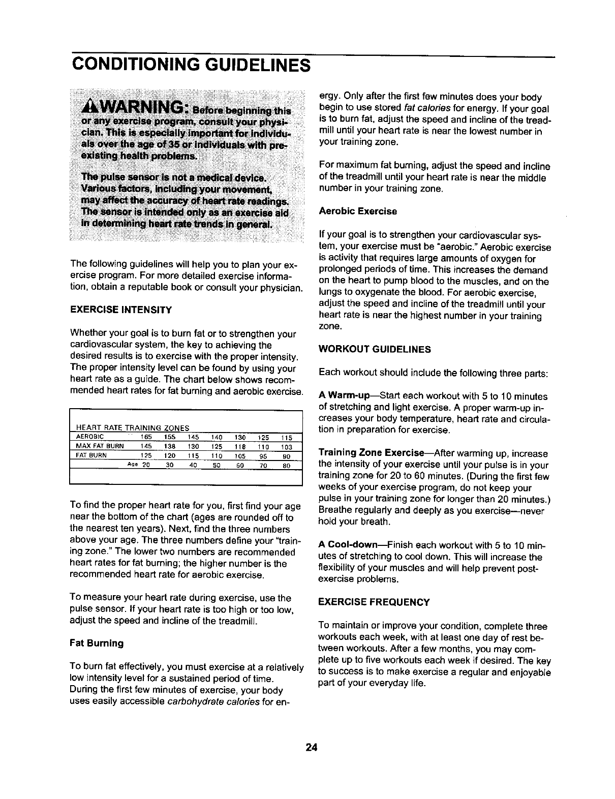
heart rate as a guide. The chart below shows recom-
mended heart rates for fat burning and aerobic exercise.
HEART RATE TRAINING ZONES
AEROBIC 165 15,5 145 140 130 t25 115
MAX FAT BURN 145 138 130 125 !18 110 103
FAT BURN 125 120 115 110 105 95 90
Ag8 20 30 40 50 60 70 80
To find the proper heart rate for you, first find your age
near the bottom of the chart (ages are rounded off to
the nearest ten years). Next, find the three numbers
above your age. The three numbers define your "train-
ing zone." The lowertwo numbers are recommended
heart rates for fat burning; the higher number is the
recommended heart rate for aerobic exercise.
To measure your heart rate during exercise, use the
pulse sensor. If your heart rate is too high or too low,
adjust the speed and inclineof the treadmill.
Fat Burning
To burn fat effectively, you must exercise at a relatively
low intensity level for a sustained period of time.
During the first few minutes of exercise, your body
uses easily accessible carbohydrate calories for en-
ergy. Only after the firstfew minutes does your body
begin to use stored fat caloriesfor energy. If your goal
is to burn fat, adjust the speed and incline of the tread-
mill until your heart rate is near the lowest number in
your training zone.
For maximum fat burning, adjust the speed and incline
of the treadmill until your heart rate is near the middle
number in your training zone.
Aerobic Exercise
If your goal is to strengthen your cardiovascular sys-
tem, your exercise must be "aerobic." Aerobic exercise
is activity that requires large amounts of oxygen for
prolonged periods of time. This increasesthe demand
on the heart to pump blood to the muscles, and on the
lungs to oxygenate the blood. For aerobic exercise,
adjust the speed and incline of the treadmill until your
heart rate is near the highest number in your training
zone.
WORKOUT GUIDELINES
Each workout should include the following three parts:
A Warm-up--Start each workoutwith 5 to 10 minutes
of stretching and light exercise. A proper warm-up in-
creases your body temperature, heart rate and circula-
tion in preparation for exercise.
Training Zone Exercise_After warmingup, increase
the intensity of your exerciseuntilyour pulse is in your
trainingzone for 20 to 60 minutes. (Duringthe first few
weeks of your exercise program,do not keep your
pulse in your trainingzone for longer than 20 minutes.)
Breathe regularlyand deeply as you exercise--never
holdyour breath.
A Cool-down--Finish each workout with5to 10 min-
utes of stretchingto cool down. This will increase the
flexibility of your muscles and will help prevent post-
exercise problems.
EXERCISE FREQUENCY
To maintain or improve your condition, complete three
workouts each week, with at least one day of rest be-
tween workouts. After a few months, you may com-
plete up to five workouts each week if desired. The key
to success is to make exercise a regular and enjoyable
part of your everyday life.
24

SUGGESTED STRETCHES
The correctform forseveralbasicstretchesisshownattheright. Moveslowlyasyoustretch--neverbounce.
1. Toe Touch Stitch
Stand with your knees bent slightly and slowly bend forward from
your hips. Allow your back and shoulders to relax as you reach
down toward your toes as far as possible. Hold for 15 counts, then
relax. Repeat 3 times. Stretches: Hamstrings, back of knees and
back.
2, Hamstring Stretch
Sit with one leg extended. Bringthe sole of the opposite foot toward
you and rest it against the inner thigh of your extended leg. Reach
toward your toes as far as possible. Hold for 15 counts, then relax.
Repeat 3 times for each leg. Stretches: Hamstrings, lower back and
groin.
3. Calf/Achilles Stretch
With one leg in front of the other, reach forward and place your
hands against a wall. Keep your back leg straight and your back
foot flat on the floor. Bend your front leg, lean forward and move
your hips toward the wall. Hold for 15 counts, then relax. Repeat 3
times for each leg. To cause further stretching of the achilles ten-
dons, bend your back leg as well. Stretches: Calves, achilles ten-
dons and ankles.
4. Quadriceps Stretch
With one hand against a wall for balance, reach back and grasp
one foot with your other hand. Bring your heel as close to your but-
tocks as possible. Hold for 15 counts, then relax. Repeat 3 times for
each leg. Stretches: Quadriceps and hip muscles.
5. Inner Thigh Stretch
Sit with the soles of your feet together and your knees outward. Pull
your feet toward your groin area as far as possible. Hold for 15
counts, then relax. Repeat 3 times. Stretches: Quadriceps and hip
muscles.
25

PART LISTmModel No. 831.294060 R oo3A
To locate the parts listed below, refer to the EXPLODED DRAWING attached in the center of this manual.
Key No. Qty. Description KeyNo. Qty. Description
1 1 Left Foot Rail 51 2
2 12 Foot Rail Screw 52 10
3 2 Isolator Bolt (Top) 53 3
4 2 Isolator Decal 54 1
5 2 Isolator Top Cap 55 1
6 2 Isolator Spring 56 1
7 2 Isolator 57 1
8 2 Isolator Bottom Cap 58 1
9 2 Isolator Bracket Cover 59 1
10 2 Isolator Bracket 60 1
11 4 Isolator Bracket Bolt 61 1
12 2 Isolator Bolt 62 2
13 1 Walking Platform 63 1
14 2 Belt Guide 64 1
15 4 Belt Guide Screw 65 1
16 2 Walking Platform Screw (Rear) 66 1
17 2 Frame Pivot Bolt 67 1
18 1 Front Roller/Pulley 68 1
19 1 Magnet 69 2
20 8 Pivot Nut 70 1
21 2 Pivot Bushing 71 1
22 1 Reed Switch 72 1
23 1 Reed Switch Screw 73 1
24 1 Reed Switch Clip 74 1
25 1Motor Tension Bolt/Lift Pivot 75 1
26 1 Motor Tension Washer 76 4
27 1 Pulley/Flywheel/Fan 77 4
28 1 Motor Pulley 78 2
29 1 Motor Star Washer 79 2
30 1 Motor Tension Nut 80 1
31 1 Motor 81 1
32* 1 Motor Assembly 82 1
33 1 Lift Frame 83 1
34 1 Right Handrail 84 1
35 2 Walking Platform Nut 85 2
36 1 Motor Pivot Bolt 86 4
37 1 Incline Motor 87 8
38 2 Incline Motor Bolt 88 2
39 10 1/4" Washer 89* 2
40 2 1° Tek Screw 90 2
41 1 Front Roller Adj. Bolt 91 2
42 2 Walking Platform Screw (Front) 92 2
43 1 Choke 93 1
44 5 Hood Screw 94 2
45 1 Console Top 95 2
46 2 Latch Screw 96 4
47 1 Reset]Off Circuit Breaker 97 1
48 1 Controller 98 1
49 1 Power Cord 99 2
50 1 Power Cord Grommet 100 2
Static Decal
3/4" Tek Screw
Belly Pan Clip
Belly Pan
Releasable Tie
Photo Switch Wire
Tie Holder Clamp
Cable Tie
Frame
Right Rear Foot
Motor Bracket
Rear Roller Adj, Bolt
Rear Roller
Allen Wrench
5/32" Allen Wrench
Left Rear Foot
Right Foot Rail
Walking Belt
Warning Decal
Filter Wire
Pulse Bar
iFIT.com Wire
iFIT.com CD
Wire Harness
Right Top Endcap
Upright Bolt
Internal Star Washer
Front Isolator Screw
Upright Spacer
Right Upright
Right Top Endcap
Latch Assembly
Controller Wire
Left Upright
Upright Endcap
Upright Bolt
U-nut
Upright Endcap (Lower)
Extension Leg Assembly
Wheel Bolt
Warning Decal
Extension Leg
Small Nut
Wheel
Leveling Foot
Extension Leg Bolt
Upright Base
Photo Switch
Base Pad
Upright Base Endcap
26

Key No. Qty. Description
101 1Console Base
102 1 Optic Disk
103 8 Ground Screw/Choke Screw
104 1 Key Clip
105 2 Fan Screw
106 1 Fan
107 1 Console
108 44 Screw
109 1 Left Tray
110 1 CD Holder
111 1 Right Tray
112 1 iFIT.com Wire
113 1 iFIT.com Jack
114 2 Motor Bracket Bolt
115 1 Photo Switch Screw
116 1 Left Handrail
117 1 Left Top Handgrip
118 1 Photo Switch Nut
119 1 Left Bottom Handgrip
120 1 Right Top Handgrip
Key No. Qty. Description
121 1 Right BottomHandgrip
122 1 Access Door
123 1 Hood
124 1 Console Back
125 1 Photo Switch Star Washer
126 2 Rear Roller Star Washer
127 4 Upright Star Washer
128 2 Front Isolator
129 2 Controller Screw
# 1 12" Green Wire, FIRing
# 1 8" Green Wire, 2 Ring
# 1 8" Red Wire, M/F
# 1 4" Black Wire, M/F
# 1 4" Blue Wire, 2F
# 1 User's Manual
*includes all parts shown in the box
#These parts are not illustrated
If a part is missing, call toll-free 1-800-999-3756.
PART IDENTIFICATION CHART
Use the drawings below to identify small parts used during assembly. Note: If a part is not in the parts bag,
check to see if it has been preattached to one of the parts to be assembled.
Latch Screw (46)-2
D
1/4"Washer
(39)-4
Extension Leg Bolt (96)-4
D©
Internal Star
Washer (77)-4
1" Tek Screw (40)-2
Console Bolt (76)-4
27

1
39
62
126 :
62
65 64
35
59
ib-78
<_1_4 128
15
103
33 _43
20 .-"
123
7O
52_ i-'44
44
8
O
0
C,o

82
79 127
9O
77 I01
'_108
79
108 85
%
,_'96
95
2O
95
109
108
112
110 45 _,_13
117
108
-116
108
108
.'-.IL
'T
108
108_
108
-4 124
5!
108
122
108
8
(
z
O_
0
0
0
Co

Your Home
For repair - in your home - of all major brand appliances, lawn and garden equipment,
or heating and cooling systems, no matter who made it, no matter who sold it!
For the replacement parts, accessories, and user's manuals that you need to do-it-yourself.
For Sears professional installation of home appliances
and items like garage door openers and water heaters.
1-800-4-MY-HOME _Anytime,dayornight
(1-800-469-4663) (U.S,A.andCanada)
www.sears.com www.sears.ca
Our Home
For repair of carry-in products like vacuums, lawn equipment,
and electronics, call or go on-line for the location of your nearest
Sears Parts and Repair Center.
1-800-488-1222 Anytime,dayornight(U.S,A.only)
www.sears.com
TO purchase a protectionagreement (U.S.A.)
or maintenance agreement (Canada) on a product serviced by Sears:
1-800-827-6655 (u.S.A) 1-800-361-6665 (Canada)
Para pedir serviciode reparacion a domieilio, y para ordenar piezas:
1-888-SU-HOGAR s_ (1-88_-7_-_27)
SEARS
® Registered Trademark /TM Trademark !SMService Mark of Sears, Roebuck and Co
® Marca Registrada /_MMarca de F&brica/s_ Marca de Servicio de Sears, Roebuck and Co,
f
FULL ONE YEAR WARRANTY
For one year from the date of purchase, if failure occurs due to defect in material or workmanship in this
Sears Treadmill Exerciser, contact the nearest Sears Service Center throughout the United States and
Sears will repair or replace the Treadmill Exerciser, free of charge.
This warranty does not apply when the Treadmill Exerciser is used commercially or for rental purposes.
This warranty gives you specific legal rights, and you may also have other rights which vary from state to
state.
Sears, Roebuck and Co., Dept. 817WA, Hoffman Estates, IL 60179
Part No. 204705 R1003A Printed in USA © 2003 Sears, Roebuck and Co.
