Proform 831297761 User Manual 725TL Manuals And Guides 99020089
PROFORM Treadmill Manual 99020089 PROFORM Treadmill Owner's Manual, PROFORM Treadmill installation guides
User Manual: Proform 831297761 831297761 PROFORM PROFORM 725TL - Manuals and Guides View the owners manual for your PROFORM PROFORM 725TL #831297761. Home:Fitness Equipment Parts:Proform Parts:Proform PROFORM 725TL Manual
Open the PDF directly: View PDF ![]() .
.
Page Count: 27
PRO.FOi M7 5 1
PER F O R M A N C ET R EA D M_|_I_
I AR8
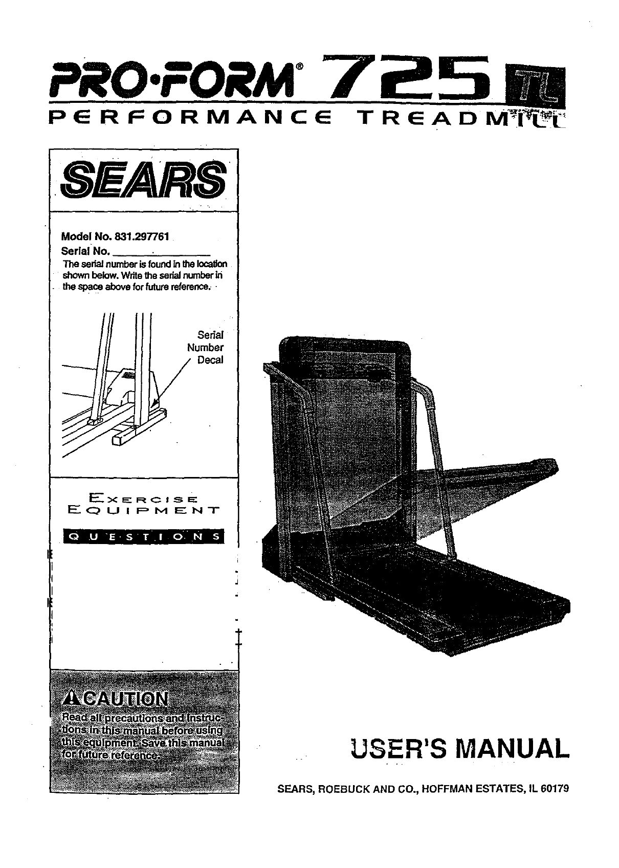
Model No. 831.297761
SeriaINo.
The sedaJnumberisfoundinthelocation
shownbelow.Writethesedalnumberin
thespace aboveforfuturereference.
Ex _- RC I S E:
E(_ U I P M Ig NT
[e] LIB :U_-gil n NoN _ i_
USER'S MANUAL
SEARS, ROEBUCK AND CO., HOFFMAN ESTATES, IL 60179
TABLE OF CONTENTS
FULL 90 DAY WARRANTY .................................................... .. ............. 2
IMPORTANT PRECAUTIONS ................ ......................................... ,.... ...3
=BEFOREYOU BEGIN...;... ................................................. ;'... ..... ;.... 5
ASSEMBLY ..................................... ;......... --- _ . .... i-:* _• • ... _, ••• .-. -.. •.... 6
.... HOW TO USE THE PULSE SENSOR .. __.. _... ;............ •,_..__.,_..._ •_.._,_.. •........,.:._.. _.., .... '..8
OPERATION AND ADJUSTMENT ................................ _....... ................... ...... '..9-.
HOW TO USE THE MANUAL MODE ........................... _'.._..... i' " """ "; ...... o-...'.. _=, •;11
HOW TO USE THE WEIGHT LOSS PROGRAMS AND THE INTERVAL pROGRAMS ... ..... ............... :13
• HOW TO USE THE FAT BURN AND AEROBIC PROGRAM •.--'. -i.. :'.,;;-- -; .. •,.. - ..... - ..... ,_15
:HOW TO USE THE FITNESS TEST PROGRAM .............. ...................... ;..... ........ 16
HOW TO FOLD AND MOVE THE TREADMILL ........ ,........................................ ;18
TROUBLE-SHOOTING ....................................... _. .............. .................. 20
CONDITIONING GUIDELINES ......................................... , ...... . .... -; ....... ... 22
ORDERING REPLACEMENT PARTS ................................... "...... :. _'......Back Cover
Note: An EXPLODED DRAWING and a PART LIST are attached to the center of this manu_L Please save them
for future reference.
FULL 90 DAY WARRANTY
For 90 days from the date of purchase, if failure occurs due to defect inmaterial or workmanship in _is ..
SEARS TREADMILL EXERCISER, contact the nearest SEARS Service Center throughout the United" :
States and SEARSwill repair or replace theTREADMILL EXERCISER, free of charge.
This warranty does not apply when the TREADMILL EXERCISER is used comme_ally or for rental pur-
poses.
This warranty gives you specific legal fights, and you may also have other dghts which vary from state
to state.
SEARS, ROEBUCK AND CO., DEPT. 817WA, HOFFMAN ESTATES, IL 60179
iMPORTANT PRECAUTIONS
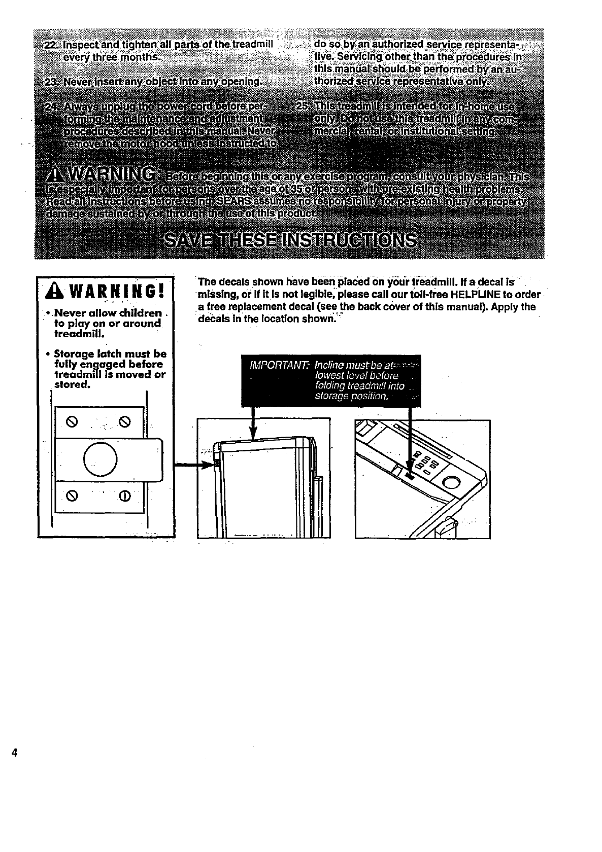
WARNING!
• Never allow children
to play on or around
treadmill.
• 5torage latch must be
fully en.qaged before
treadmill is moved or
stored.
Q i ,_)
._H.-
'The decals shown have beeh.placed €)n _i_ur t:_eadmlll. If a decal Is .
missing, or If [t ls not legible, please call our toll-free HELPLINE to order.
.a free replacement decal (see the back cover of this manual). Apply the
decals Inthe location shown.'"
4
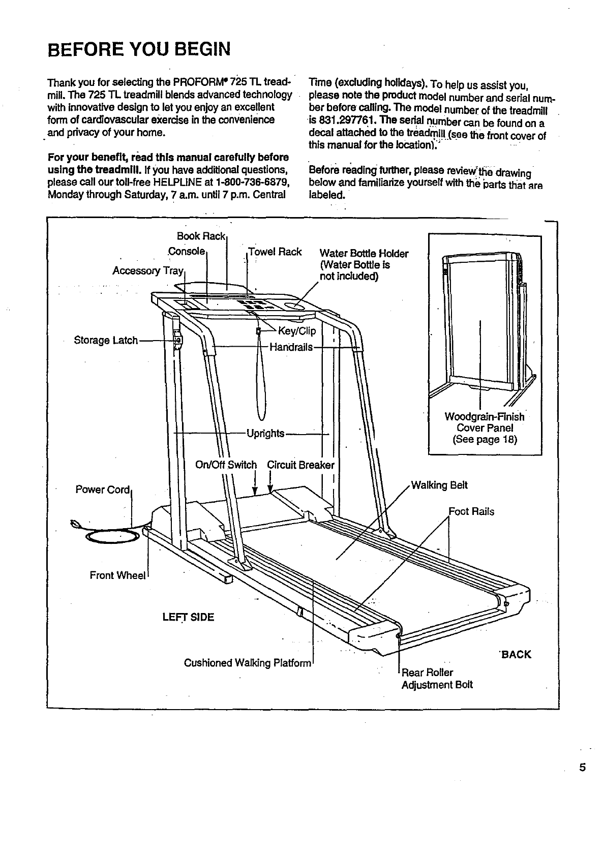
BEFORE YOU BEGIN
Thank you for selecting the PROFOR/vP 725 TL tread- Time (excluding holidays). To help us assist you,
mill. The 725 TL treadmill blends advanced technology please note the product model number and serial hum-
with innovative design to let you enjoy an excellent bet beforecalling. The model number of the treadmill
form of cardiovascular exercise in the convenience
•and privacy of your home.
For your benefit, read this manual carefully before
using the treadmill. If you have addiUonalquestions,
please call our toll-free HELPLINE at 1-800-736-6879,
Monday through Saturday, 7a.m. until7 p.m. Central
is 831.297761. The serial number can be found on a
decal attached to the treadmi!l (see the front cover of
this manual for the Iocationl_' ._
Before reading further, please mview"t_e drawing
below and familiarize yourself with th_ parts that are
labeled.
console Rack Water Bottle Holder
(Water Bottle is
not included)
Stomgq
On/Off Switch Cimuit Breaker
Power (
Woodgraln'Finish
Cover Panel
(See page 18)
Belt
=oot Rails
Front Wheel
LEFT'.SIDE
Cushioned Walking Plaffom Rear Roller
Adjustment Bolt
"BACK
5
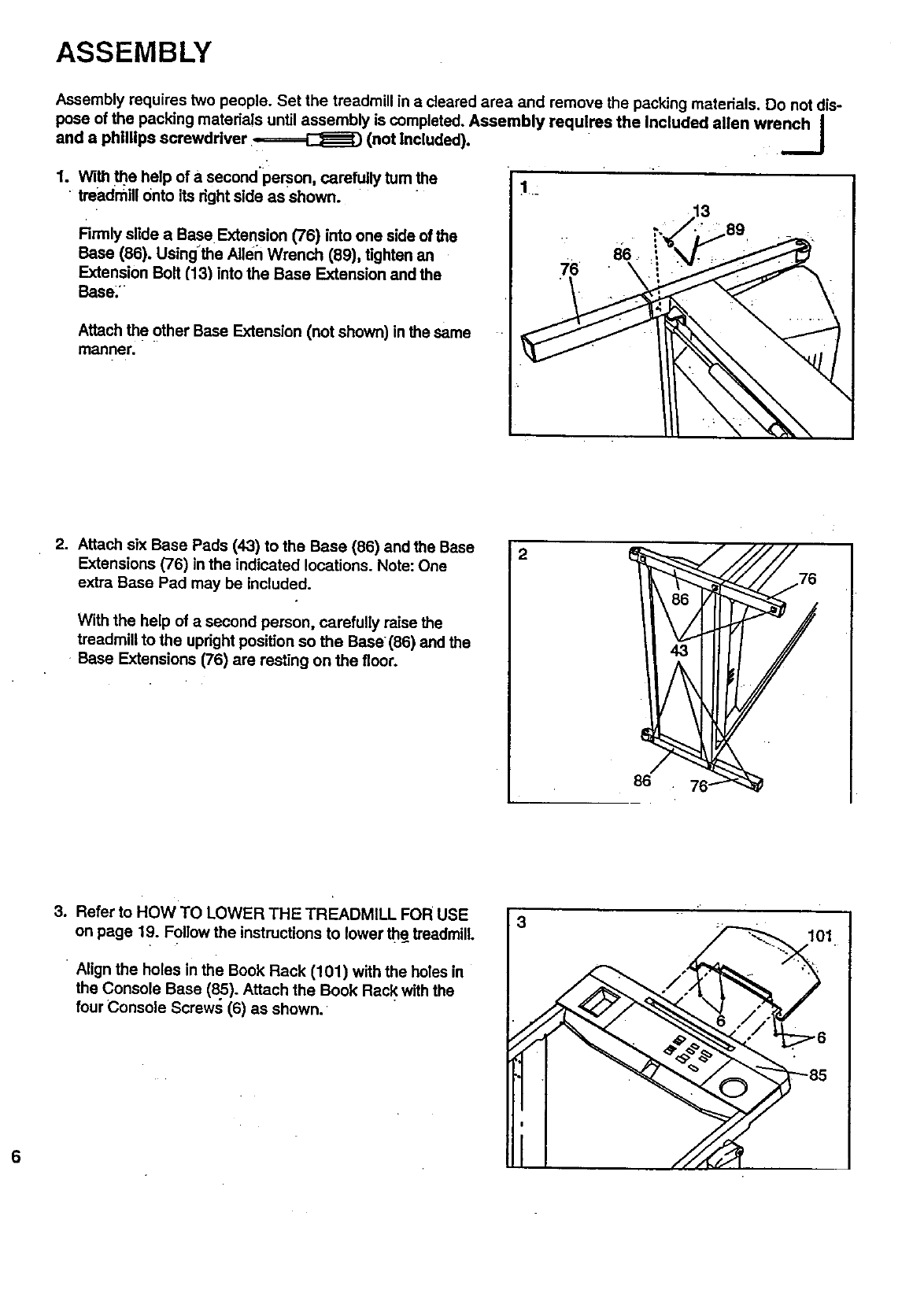
ASSEMBLY
Assembly requires two people. Set the treadmill in acleared area and remove the packing materials. Do not dis-
pose of the packing mateda!s until assembly is completed. Assembly requires the Included allen wrench I
and a phillips screwdriver ,-====_ (not Included). __J
1. With _e help of a second person, carefully tum the 1
treadmill Onto its right side as shown. -
Rrmly slide aBase Extension (76) into one side of the
Base (88). Using'the Allen Wrench (89), tighten an 86
Extension Bolt (13) into the Base Extension and the 76 \'
Base:
Attach the other Base Extension (not shown) in the same
manner.
2. Attach six Base Pads (43) to the Base (86) and the Base
Extensions (76) in the indicated locations. Note: One
extra Base Pad may be included.
With the help of a second person, carefully raise the
treadmill to the upright position so the Base (86) and the
Base Extensions (76) are resting on the floor.
2
86
3. Refer to HOW TO LOWER THE TREADMILL FOR USE
on page 19. Follow the instructions to lower the treadmill.
Align the holes in the Book Rack (101) with the holes in
the Console Base (8.5). Attach the Book Rack with the
four Console Screws (6) as shown. •
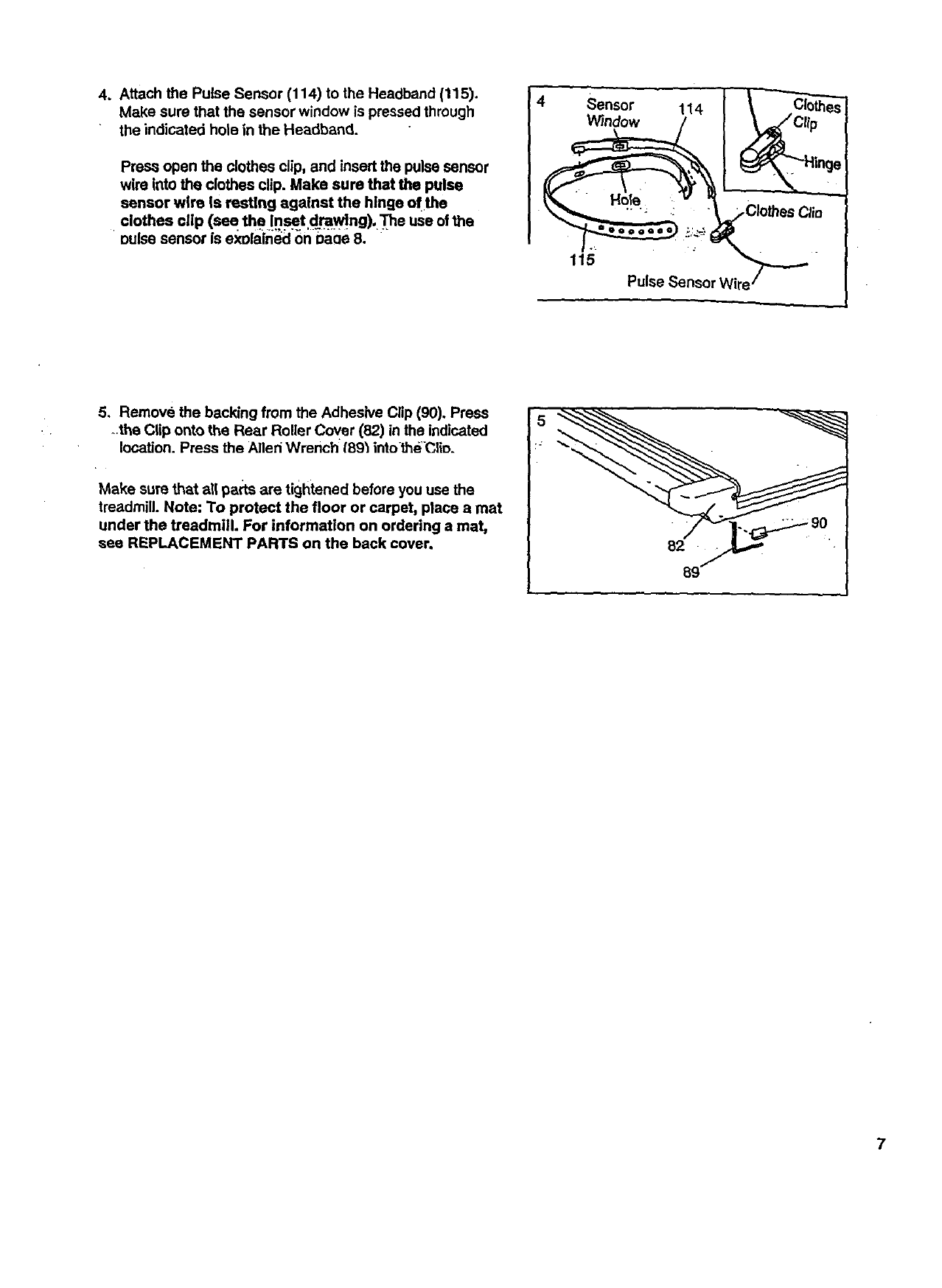
4. AttachthePulseSensor(114)totheHeadband(115).
Makesurethatthesensorwindowispressedthrough
theindicatedholeintheHeadband.
PreSsopentheclothes clip, and insert the pulse sensor
wire Into the clothes clip. Make sure that the pulse
sensor wire is resting against the hinge of the
clothes clip (see the Inset.drawing), "[he use of the
•oulse sensor is exolain_:l_r_ baoe 8. "
Sensor
Window
Pulse Sensor Wire
5. Remove the backing from the Adhesive Clip (90). Press
the Clip onto the Rear Roller Cover (82) in the indicated
location. Press the Alleri Wrench' tBg_intothe"Clio.
Make sure that all parts are tightened before you use the
treadmill. Note: To protect the floor or carpet, place a mat
under the treadmill. For information on ordering a mat,
see REPLACEMENT PARTS on the back cover.
:J
7
HOW TO USE THE PULSE SENSOR
8
The unique headband-style pulse sensor is specially
designed for greater accuracy, comfort, and durability.
-To get the beat performance from the pulse sen-
sor, please read the foUowing instructions.
:HOW TO ADJUST THEHEADBAND
For the pulse sensor to function propedy, the heed-
band should fit snugly around your head, without being
uncomfortable.
To adjust _
headband, in-
sert thead-
justmenttab
through one
of the holes
in _e head-
band. Note:
Each-tlme
you exer-
cise, the headband may expand slightly during the
first few minutes of use. It may be necessary to
readjust the headband periodically.
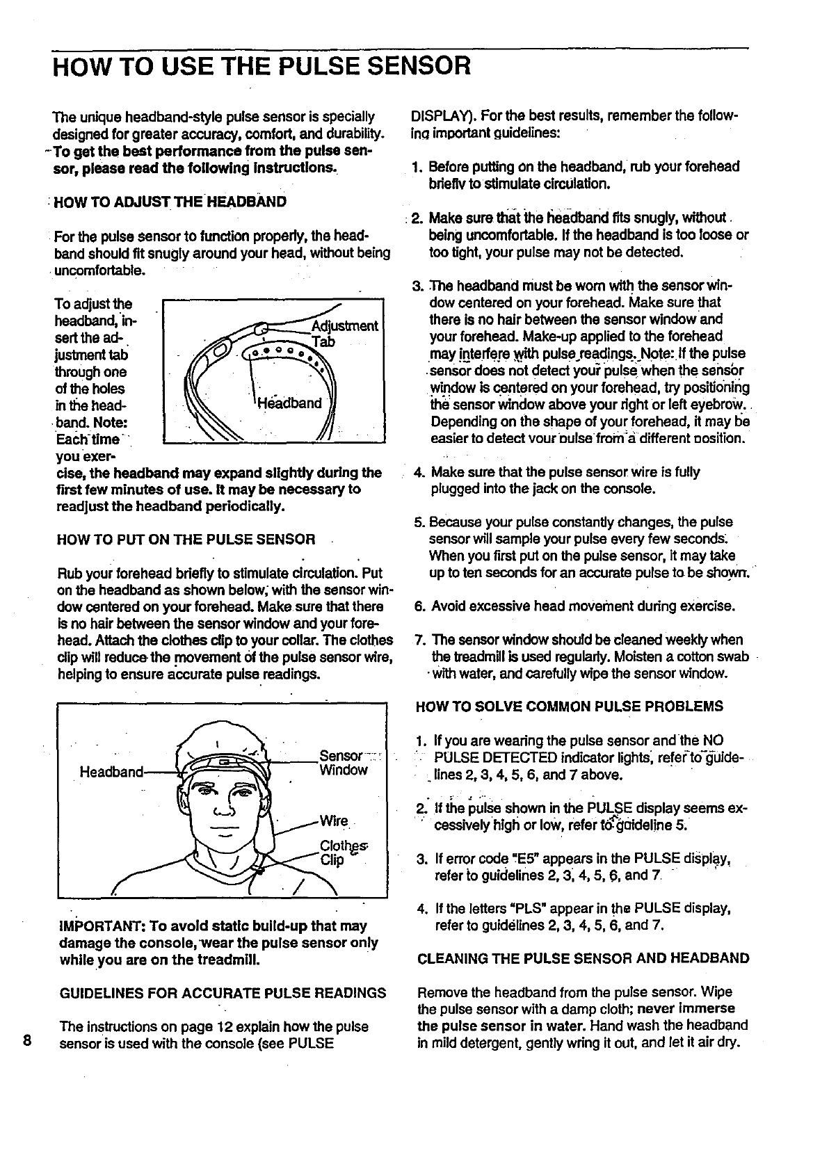
HOW TO PUT ON THE PULSE SENSOR
Rub your forehead bdefly to stimulate cimulation.'Put
on the headband as shown below; with the sensor win-
dow centered on your forehead. Make sure that there
is no hair between the sensor window and your fore-
head. Attach the clothes clip to your collar. The clothes
clip will reduce the .movement Ofthe pulse sensor wire,
helping to ensure accurate pulse readings.
Sensor-:
Window
Cloth_s:
./
IMPORTANT: To avoid static build-up that may
damage the console, wear the pulse sensor only
while.you are on the treadmill.
GUIDELINES FOR ACCURATE PULSE READINGS
The instructionson page 12 explain how the pulse
sensor is used with the console (see PULSE
DISPLAY). For the best results, remember the follow-
inclimportant guidelines:
1. Before putting on the headband, rub your forehead
bdeflv to stimulate circulation.
:2. Make sure that the headband fits snugly, without.
being uncomfortable. If the headband is too loose or
too tight, your pulse may not be detected.
3. The headband must be worn with the sensor win-
dow centered on your forehead. Make sure that
there is no hair between the sensor windowand
your forehead. Make-up applied to the forehead
may interfere ..withpulse reedings.. Note: If the pulse
•sensor does not detect you_pulse when the sensbr
window is centered on your forehead, try positidning
the sensor window above your dght or left eyebrow,
Depending on the shape of your forehead, it may be
easier to detect your oulse fmm'a different position.
4. Make sure that the pulse sensor wire is fully
plugged into the jack on the console.
5. Because your pulse constantlychanges, the pulse
sensor will sample your pulse every few seconds:
When you first put on the pulse sensor, it may take
up to ten seconds for an accurate pulse to be shown.
6. Avoid excessive head movement dudng exemise.
7. The sensor window should be cleaned weekly when
the treadmill is used regularly. Moisten a cotton swab
•with water, and carefully wipe the sensor window.
HOW TO SOLVE COMMON PULSE PROBLEMS
1. If you are weadng the pulse sensor and the NO
:'- PULSE DETECTED indicator lights; refer-!o-_uide-
. lines 2, 3, 4, 5, 6, and 7 above.
2; If the pulse shown in the PULSE display seems ex-
cessivelyhlgh or low, refer t0:_01deline 5;
3. If error code "E5" appears in the PULSE display,
refer to guidelines 2, 3; 4, 5, 6, and 7
4. If the letters =PLS" appear in the PULSE display,
refer to guidelinea 2, 3, 4, 5, 6, and 7.
CLEANING THE PULSE SENSOR AND HEADBAND
Remove the headband from the pulse sensor. Wipe
the pulse sensor with a damp cloth; never immerse
the pulse sensor in water. Hand wash the headband
in mild detergent, gently wdng it out, and let it air dry.
OPERATION AND ADJUSTMENT
THE PERFORMANT LUBE TM WALKING BELT
Your treadmill features a walking belt coated With
PERFORMANT LUBE TM, a high-performance lub_e,ant.
IMPORTANT:Neverapply silicone spray or other :i
substances to the_walklng belt or the walking plat-
form. They will deteriorate the walking belt and
cause excessive wear.
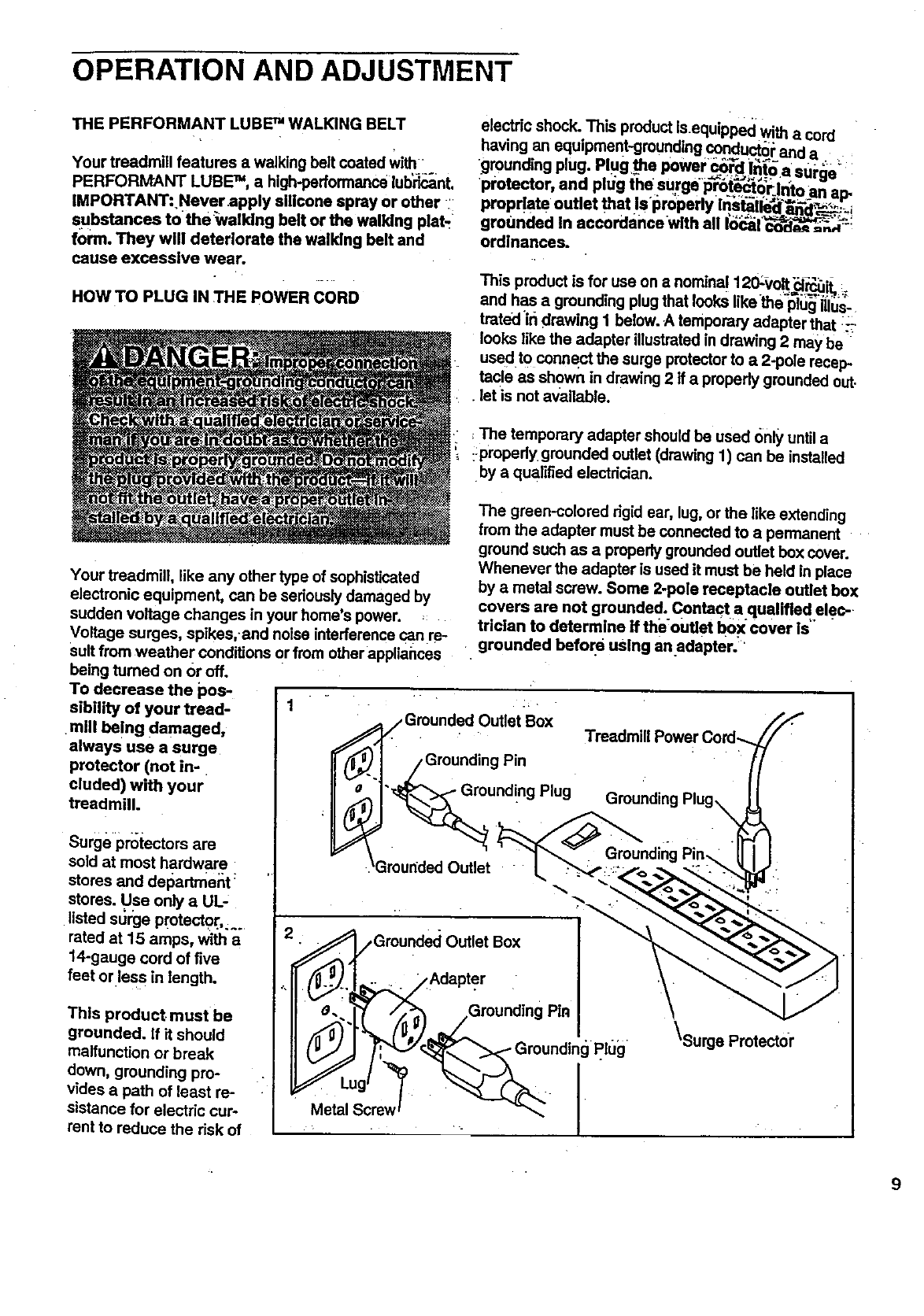
HOW TO PLUG IN THE POWER CORD
electric shock. This product is e ui e•^^..,
.... q pp d w!th a ,.ulu
navmg an equlpmem-gmund!ng condu_or and a
grounding plug. Plugthe power_'_dlnt_ a surge :
pl;otector, and plug the surge i_t_'rjn_to an ap.
proprlata outlet that Is i_r0perly in_t_ile_',_--._._ =
grounded In accordancewith all I_1"_i
ordlnancas.
This product is for use on anominal.120:_,olt_1_=r_q_it......
and has a grounding plug that looks likethe_l;_ i{lus-
trated ir_drawing 1 below. A temporary adapter that ::-i
looks like the adapter illustratedin drawing 2 may be
used to connect the surge protector to a2-pole recep-
tacle as shown in drawing 2 if a propedy grounded out.
•let is not available.
The temporary adapter should be used only until a
::pl'opedygrounded out et (drawing 1) can be installed
by a qualified electrician.
Your treadmill, like any other type of sophisticated
electronic equipment, can be seriously damaged by
sudden voltage changes in your home's power.
Voltage surges, spikes,.and noise interference can re-
sult from weather conditions or from other appliances
being turned on or off.
The graen-colored rigid ear, lug, orthe like extending
from the adapter must be connected to a permanent
ground such as a properly grounded outlet box cover.
Whenever the adapter is used it must be held in place
by a metal screw. Some 2-pole receptacle outlet box
covers are not grounded. Contact a qualified elec-
trician to determine If theoutlet b0xcover is"
grounded before using anadapter.
To decrease the pos-
sibility of your treed-
mill being damaged,
always use a surge
protector (not in-
cluded) with your
treadmill.
Surgeprotectorsare
sold at most hardware
stores and del_dment:
stores. Use only a UL-
listed stJrge pmtecto[,_..
rated at 15 amps, with a
14-gauge cord of five
feet or less in length.
This product, must be
grounded. If it should
malfunction or break
down, grounding pro-
vides a path of least re-
sistance for electric cur-
rent to reduce the risk of
Grounded Outlet Box
Grounding Pin
"_unding Plug
Grounded Outlet
Treadmill
•_Grounded Outlet Box
Adapter
o:...l'l_ /, ;g:_ __Grounding Pin
Metal Screw
\Surge Protector
9

_0
DIAGRAM OF THE CONSOLE
Note: If there is.a thin._sheetof €lea_t;plas-
tic on the face of the console; rem0Ye p,.
FEATURES OF THE "CONSOLE
The treadmill console offers an impressive array of fea-
tures designed to make your workouts more effective
and enjoyable. When the console is in the manual mode,
the speed ahd Incline of the treadmi!l can be'changed _-.
with a touch of a button. As you exerdse, five displays •
will provide continuous exercise feedback. Seven preset
programs are also offered: two WEIGHT LOSS programs
and two INTERVAL programs automatically control the
speed of the treadmill as they guide you through effective
workouts; the special FAT BURN program provides In-
tensive fat-burning workouts; the AEROBIC program"_:
helps you to achieve maximum cardiovascular benefits;
_andthe uni_lue FITNESS TEST program measures your
•relative fdness lei/el. -
To use the manual mode, follow the steps on pages 11
through 13. To usdthe WEIGHT LO.SS.oi"INTERVAl. ,.
.programs, see pages 13 and 14."1"0use the FAT BURN
or AEROBIC program, see pa"g_es_.45:an,d !6. To use the
FITNESS TEST program, see pages 16 _m'dt7. Note:--
The console can displayspeed and distance in.i_'_.er".
miles or kilometers (sEe SPEED DISPLAY _r_a_"t2): _ •
For simplicity,all instructionsin this manuel refer to miles.
Before beginning;make sure
that the on/off switch located
near the power cord is in the
.=on"position, Plug in the power
cord (see page 9). Note: If the -
Position
key is in the console when the
power cord is plugged in, the letters 'PO" will flash in the
SPEED display. If this occurs, remove the key.
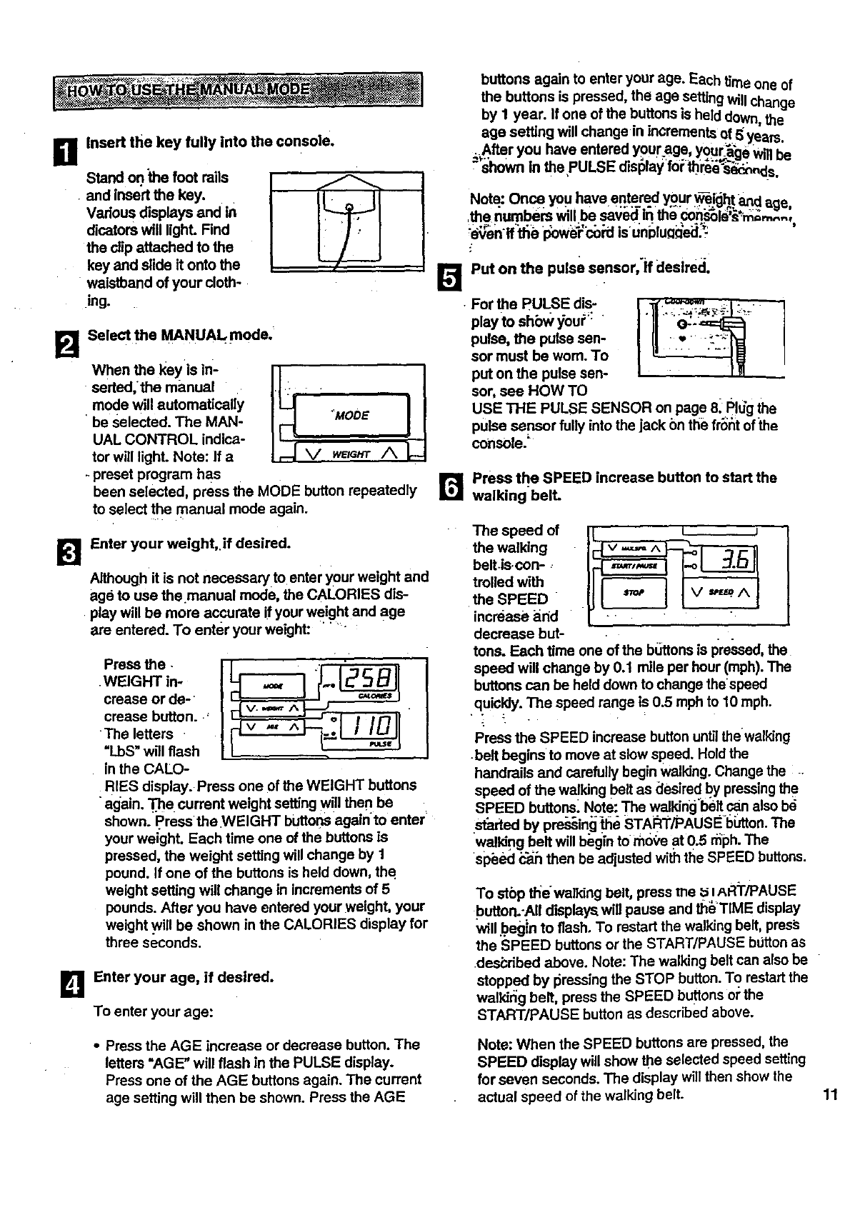
BStand on.the foot rails
• and insert the key.
Various displays and in
dicators will lighL Find
the clip attached to the
key and slide it onto the
waistband of your cloth-
ing.
Insert the key fully into the console.
B Select the MANUAL mode.
seded,the manual
mode will automatically
be Selected. The MAN- "MOOE
UAL CONTROL indica-
tor will light. Note: If a I _ V w_G_ /k
-preset program has
been selected, press the MODE button repeatedly
to select the manual mode again.
[_l Enter your weight,.if desired.
Although it is not necessary to enter your weight and
age to use the.manual mode, the CALORIES dis-
play will be more accurate if your weight and age
entered. To enter your weight: .....
.WEIGHT in-
creese or de-
crease button..' v..,=,,, ^
The letters . v ,., ^ ..
"LbS" will flash
in the CALO-
RIES display. Press one of the WEIGHT buttons
again...The current weight setting will then be
shown. Press the WEIGHT buttonsagainto enter
your weight. Each time one of the buttons is
pressed, the weight setting will change by 1
pound. If one of the buttons is held down, th(!
weight setting will change in increments of 5
pounds. After you have entered your weight, your
weight will be shown in the CALORIES display for
three seconds.
DEnter your age, if desired.
To enter your age:
buttons again to enter your age. Each time one of
the buttons is pressed, the age setting Willchange
by 1 year. If one of the buttons is held down, the
age setting Will change in Increments of 5 years.
_.After you have entered your age, your_be _,_1h=
• shown in the PULSE display for tl?reese_nds.
[]
Note: Once you have entered your _!gh! _ age,
the r_umbera Willbe sav_J in the connie ._i_;,_,.,,
even ffthe power cord is unnlu_ned:
Put on the pulse sensor,'if deslreci.
•For the PULSE dis-
play to show you_':
pulse, the pulse sen-
sor must be wom. To
put on the pulse sen-
sor, see HOW TO
USE THE PULSE SENSOR on page 8_Plug the
pulse sensor fully into the jack on the fr_t of _e
console."
r_ Press the SPEED increase button to start the
walking bell
The speed of
the walking
belt iscon-
trolled with
the SPEED
increase arid
decrease but-
t
tons. Each time one of the b_ttons is pressed, the
speed will change by 0.1 mile per hour (mph). The
buttons can be held down to change the'speed
quicldy. The speed range is 0.5 rnphto 10 mph.
• - _•
Press the SPEED increase button untilthe walking
-belt begins to move at _ow speed. Hold the
handrails and carefully begin walking. Change the
speed of the walking belt as desired by pressingthe
SPEED buttons. Note: The wall_in_jbeltFan also be
istaded by preying _e STAPCI_/PAUSEbiJtton.The
walking belt will begin to tho9e at 0.5 rnph.The
speed _ then be adjusted withthe SPEED buttons.
To stop thewalldng belt, press the uIAR"I'/PAUSE
button.-AII displays,will pause and theTIME display
willbegin to flash. To restart the walking belt, pres_
the SPEED buttons or the START/PAUSE button as
described above. Note: The walking belt can also be
stopped by 16ressingthe STOP button. To restart the
walking belt, press the SPEED buttonsor the
START/PAUSE button as described above.
•Press the AGE increase or decrease button. The
letters "AGE" will flash in the PULSE display.
Press one of the AGE buttons again. The current
age setting will then be shown. Press the AGE
Note: When the SPEED buttons are pressed, the
SPEED display will show the selected speed setting
for seven seconds. The display will then show the
actual speed of the walking belt. 11
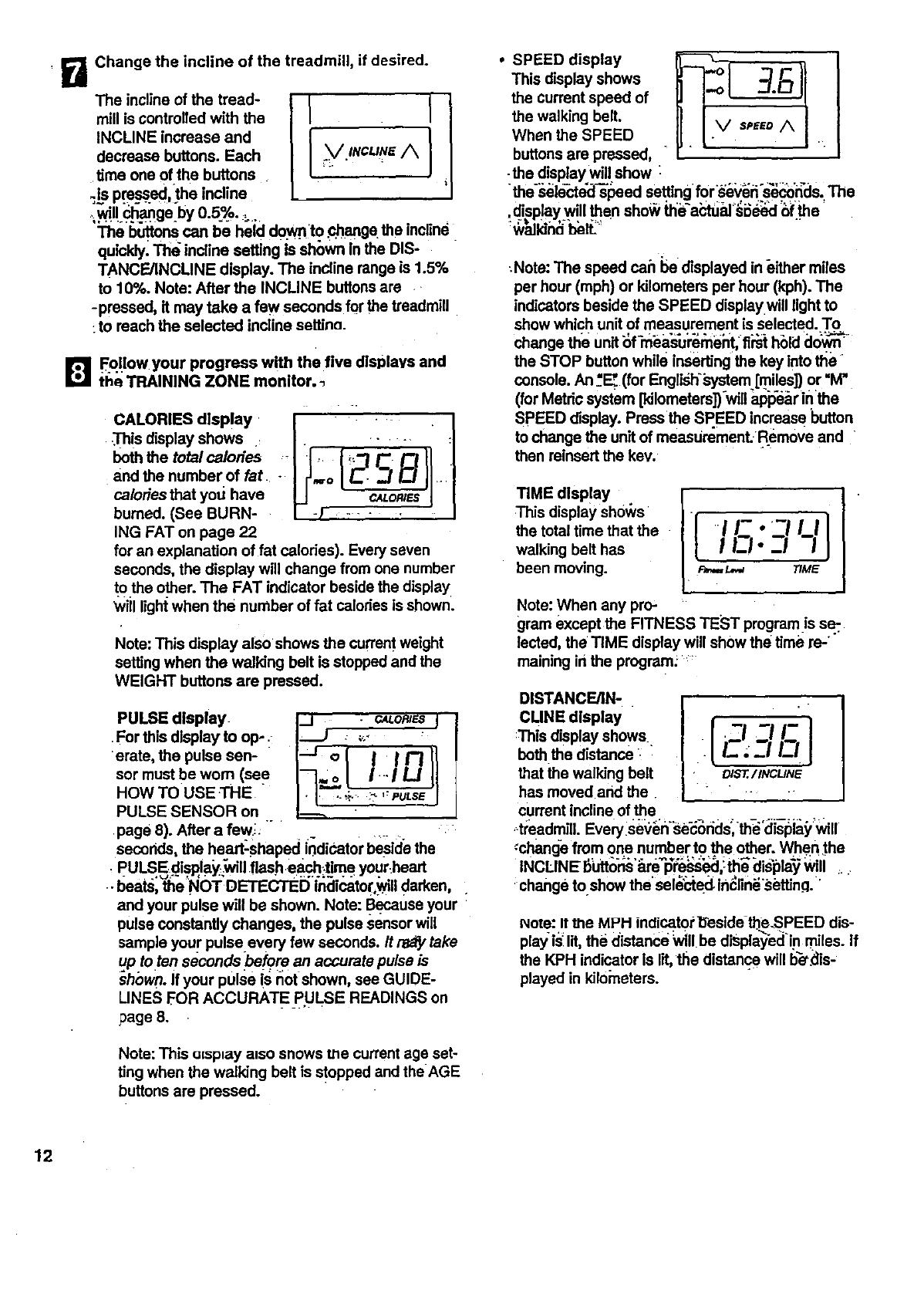
BChange the incline of the treadmill, if desired.
The incline of the tread- l[
mill is controlled with the I
INCLINE increase and
decrease buttons. Each _/INCUNE/_
time one of the buttons
_ls pressed,the incline
, byo.5 o..
The buttons can be held d0.wr!.to..change the incline
quickly. The incline setting Is sh6wn In the DIS-
TANCE/INCLINE display. The incline range is 1.5%
to 10%. Note: After the INCLINE buttonsare .-
-pressed, it may take a few seconds for the treadmill
:to reach the selected incline settina.
[] Follow your progress with the five dlsl_lavs and
the TRAINING ZONE monitor.
CALORIES disPlay
This display shows •
both the total calories
and the number of fat -
calories that yotJ have
burned. (See BURN-
ING FAT on page 22
I
, 'Es!I
for an explanation of fat calories). Every seven
seconds, the display will change from one number
t0 the other. The FAT indicator beside the display
Will lightwhen the number of fat calodes is shown.
Note: This display also shows the currentweight
setting when the walking belt is stopped and the
WEIGHT buttons are pressed.
PULSE display.
For this display to olP:
erate, the pulse sen-
sor must be worn (see
HOW TOUSE.THE "
PULSE SENSOR on
page 8). After a few;: "
I °1 Ilrl
I-]=L'ZFo
seconds, the hea_shaped indicator beside the
, PULSEdisRiay_vill flash each_me your_heart
. I_eats"the _NOT;DETECTED'i'r_Ii_tor _11darken,
and your pulse will be shown. Note: Because your
pulse constantly changes, the pulse sensor will
sample your pulse every few seconds. It rs_y take
up totan seconds lbe_qre an accurate pulse is
shown. If your pulse is not shown, see GUIDE-
LINES FOR ACCURATE P.ULSE READINGS on
page 8.
Note: This uJsp_ayalso snows me current age set-
ting when the walking belt is stopped and the AGE
buttons are pressed.
SPEED display
This display shows
the current speed of
the walking belt.
When the SPEED
buttons are pressed,
•the display will show "
thesele_e_l-@'l_eed se_ing for i,_i_S_Kds. ' The
.display will then sho_ _e'a_tual'_i_:l _f the
:Note: The speed can be displayed in either miles
per hour (mph) or kilometers per hour (kph). The
indicators beside the SPEED displaywill light to
show which unit of measurement is selected. To
change the unit of measurement, first hold down
the STOP button while inserting the key into the
console. An_'E_(for English'_-ystem[miles]) or =M"
(for Metric system [kilometers])will ap'p'ebrinthe
SPEED display. Press the SPEED increase button
to change the unit of measuremenL Remove and
then reinsert the kev.
TIME disPlaY
This display sh0ws
the total time that the
walking belt has
been moving.
IEl- _1
F_ I._._ TIME
Note: When any pro-
gram except the FITNESS TEST programis seT.
lected, the TIME display will show the time re-
malning in the program.'
DISTANCE/IN-
CUNE display I, I
:Thisdisplay sh°ws l.ZI ._._ ./._
boththe distance I- ;_1 I_1
that the walking belt o_../INCLINE
has moved and the.
current incline of the
,_treadmill. Every se_i_n_se_rid_th_°cJisl_ a_iwi
:change from one number to the other. When _the
INCLINEl_ton._'_re_l@_:e_,!_ bis'l_la'_ will :.
change to.show thesel_e(_ indlin_settina.
_ote: It me MPH indicatorl:_eside the.SPEED dis-
pay is. d, the distance wi be d=spayed i.n mles. f
the KPH indicator Is lit the distance will b_is-
played in kilometers.
12
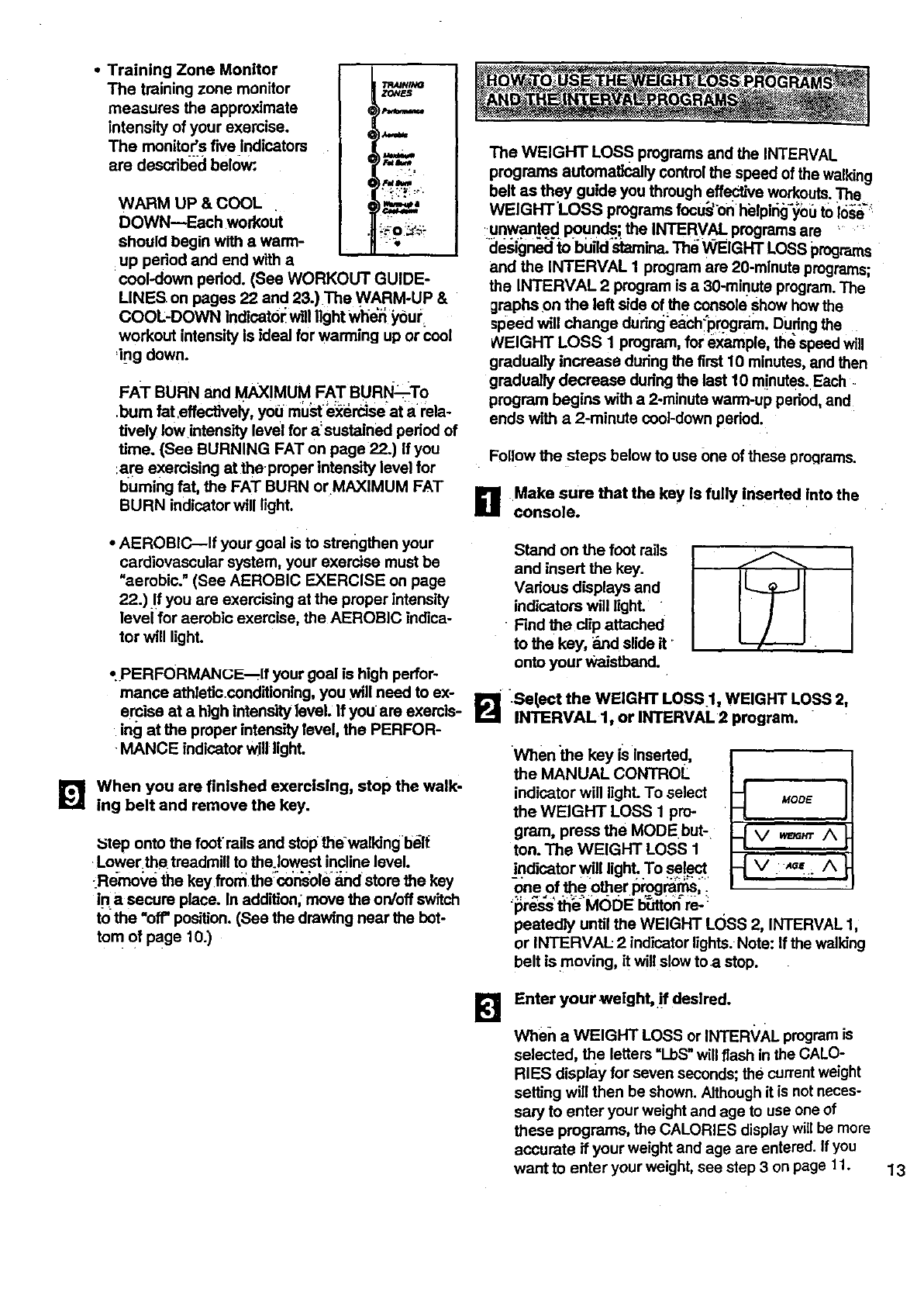
Training Zone Monitor
The training zone monitor
measures the approximate
intensity of your exercise.
The monitor's five Indicators
are descdl_ecl below:
WARM UP & COOL
DOWN--Each workout
should begin witll awarm-
up pedod and end with a
TR4_/INO
ZONES
pI_mM_Ce
_==,._.
'FO_?
cool-down pedod. (See WORKOUT GUIDE-
LINES on pages 22 and 23.)The WARM-UP &
COOL-DOWN thdlcat6_ will light Whe_ ybu_;
workout intensity is ideal for warming up or cool
=ing down.
FAT BURN and MAXIMUM FAT BURN:--To
.bum fat.effectively, you mU_ i_erdse'at arela-
tively low intensity level for a=sustained pedod of
Ume. (Sea BURNING FAT on page 22.) If you
:are exercising at the-proper intens'dy level for
burning fat, the FAT BURN orMAXIMUM FAT
BURN indicator will light.
•AEROBIC--If your goal is to strengthen your
cardiovascular system, your exercise must be
"aerobic." (See AEROBIC EXERCISE on page
22.) .!fyou are exercising at the proper intensity
level for aerobic exercise, the AEROBIC indica-
tor will IighL
•.PERFORMANGE--ff your goal is high perfor-
mance athletic.conditioning, you _ll need to ex-
ercise at a high intensity level. If you are exercis-
ing at the proper intensity level, the PERFOR-
MANCE indicator will lighL
_'_ When you are finished exercising, stop the walk-
ing belt and remove the key.
:step onto the footroils and stop thewalldng b_lt
Lower.the. treadmill to the.lowest incline level.
_Reroo_,e the key fron_ the0onsole _and store the key
in a secure place. In addition; move the on/off switch
to the "off"position. (See the drawing near the bot-
tom of page lO.)
The WEIGHT LOS S programs and the INTERVAL
programs automatically control the speed of the walking
belt as they guide you through effective workouts. The
WEIGHT'LOSS programs focu:s'bnhblping_0t_ to io._ _'
uqwanted P0unds...;the INTERVAL programs are _ '
designed to build stamina. The WEIGHT LOSS programs
and the INTERVAL 1 program are 20-mlnute pmgrems;
the INTERVAL 2 program is a30-mirlute program.The
graphs on the left side of the console show how the
speed will change dudngeach_pr._ram. During the
_/EIGHT LOSS 1 program, for example, the speed will
gradually increase dudng the first 10 minutes, and then
gradually decrease dudng the last 10 minutes. Each
program begins with a 2-minute warm-up pedod, and
ends with a 2-minute cool-down pedod.
Follow the steps below to use One of these proclrams.
DMake sure that the key is fully !nserted Into the
console.
Stand on the foot rails
and insert the key.
Vadous displays and
indicators will light.
• Find the clip attached
to the key, _md slide it
onto your Waistband.
B .Sel,ect the WEIGHT LOSS 1, WEIGHT LOSS 2,
INTERVAL 1, or INTERVAL 2 program.
When the key is inserted,
the MANUAL CONTROL
indicator will lighL To select
the WEIGHT LOSS 1 pro-
gram, press the MODEbut-
ton. The WEIGHT LOSS 1
_indicator v_illlight .To se!_.
oneof the other programs,.
'_re_s'thi_: MODE b_dt0_re -_
pestedly until the WEIGHT LOSS 2, INTERVAL 1,
or INTERVAL: 2 indicator lights. Note: If the walldng
belt is moving, it will slow to a stop.
MODE
{ V Aa_. /k
lg Enter your welght,•!f desired.
When a WEIGHT LOSS or INTER_/AL program is
selected, _e letters =l_bS"will flash in the CALO-
RIES display for seven seconds; the current weight
setting will then be shown. Although it is not neces-
sary to enter your weight and age to use one of
these programs, the CALORIES display will be more
accurate if your weight and age are entered. If you
want to enter your weight, see step 3 on page 11. 13
14
B Enter your age, If desired.
After you have completed step 3, the letters "AGE"
will flash in the PULSE display for seven seconds;
the current age setting will :then be shown. If you
•want to enter your age, see step 4 on page 11.
R Put on the pulse sensor, if deslred_
or ePuLs pay I
r;use,the
pulse sensor must be
worn. To put on the
pulse sensor, see HOW ] :-_:_,a _'_'--J _ : I
"1"(3USETHE PULSE
•SENSOR 0; page 8.
.Pug _e pulse sensor fuli_;into _e jack on.the front
;ofthe co.nsole. '
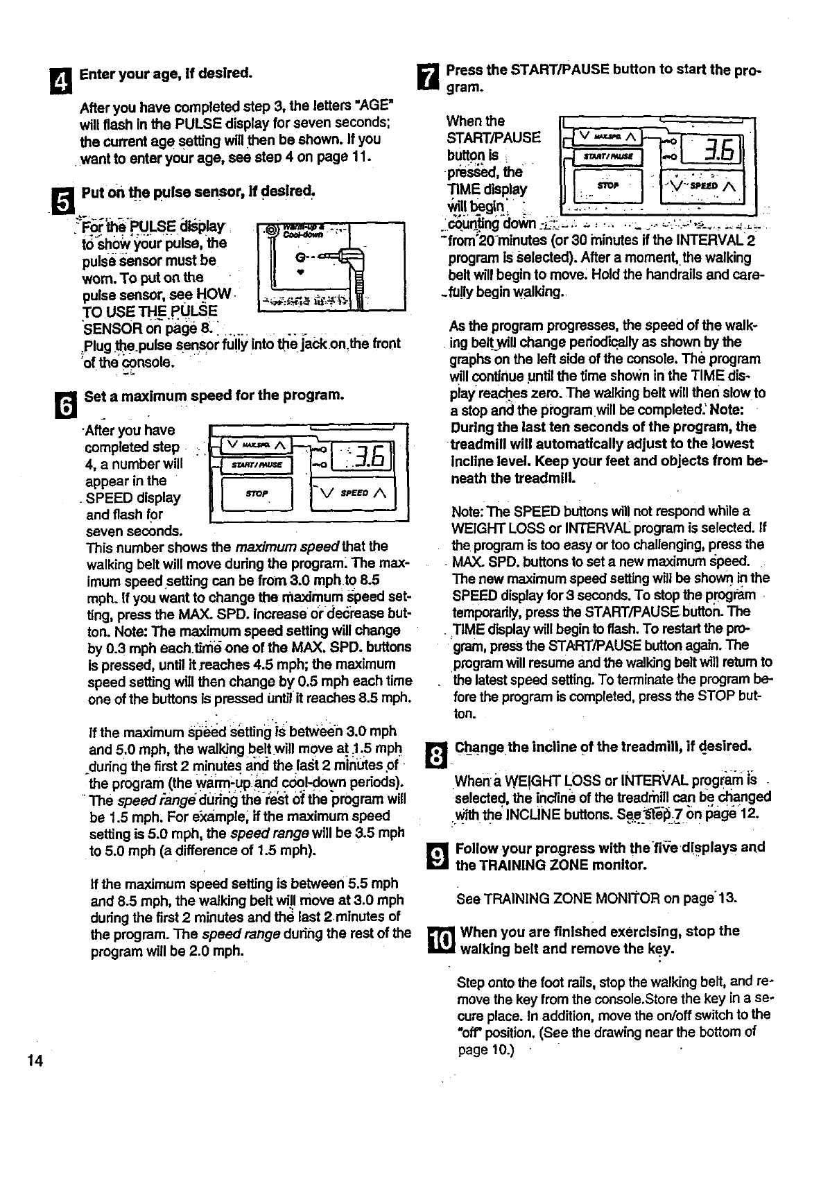
R Set a maximum speed for the program.
completed step :.
4, a number will
appear in the
seven seconds.
This number shows the maximum speedthat the
walking belt will move during the program. The max-
imum speedsetting can be from 3.0 mph to 8.5
mph. If you want to change the maximum speed set-
ling, press the MAX. SPD. increase 0r deci'ease but-
ton. Note: The maximum speed setting will change
by 0.3 mph each.time one of the MAX. SPD. buttons
is pressed, until it•reaches 4.5 mph; the maximum
speed setting will then change by 0.5 mph each time
one of the buttons is pressed until it reaches 8.5 mph.
If the maximum sighedSetfing_isbetween 3.0 mph
and 5.0 mph, the walking b.eltwill move a.t_1.5 mph
during the first 2 minutes and the last 2 minCes,of
_the program (the warm-upland coo.l-down periods),
• The speed Pange dudrlgthe rest of the'program will
be 1.5 mph. For example, if the maximum speed
setting is 5.0 mph, the speed range will be 3.5 mph
to 5.0 mph (a difference of 1.5 mph).
if the maximum speed setting is between 5.5 mph
and 8.5 mph, the walking belt will move at 3.0 mph
during the first 2 minutes and the last 2minutes of
the program. The speedrange during the rest of the
program will be 2.0 mph.
B Press the START/PAUSE button to start the pro-
gram.
START/PAUSE
button is= =_=r,_=_ jI..o31_ .D I
pre ed,the .....
................
coun-Ungclo_/_'n_-L-;!_=:.'. _-..... _ .... -.:-- .:_-...........
"from'2O-minutas (or 30 minutes if the INTERVAL
program is Selected). After a moment, the walkin
belt will begin to move: Hold the handrails and care-
.f/J!ly begin walking.
As the program progresses, the speed of the walk-
ing bell;_will change periodically as shown by the
graphs on the left side of the console. The program
will continue until the time shown in the TIME dis-
play reaches zero, The walking belt will then slowto
a stop and the programwill be completed: Note:
During the last ten seconds of the program, the
treadmill will automatically adjust to the lowest
incline level. Keep your feet and objects from be-
neath the treadmill.
Note:The SPEED buttonswill not respond while a
WEIGHT LOSS or INTERVAL program is selected, if
the program is too easy or too challenging, press the
MAX. SPD. buttonsto set a new maximum speed.
The new maximum speed setting will be shown inthe
SPEED displayfor3 seconds. To stop the pl'ogmm
temporarily, press the START/PAUSE button. The
•TIME display will begin to flash. To restart the pro-
gram, pressthe START/PAUSE buttonagain. The
program will resume and the walking belt wfilreturn to
the latest speed setting.To terminate the program be-
fore the program is completed, press the STOP but-
ton.
_Ch_angethe incline of the treadmill, if d_esired.
whena WEIGHT I_OSS or INTER_/AL prog(arn is -
selected the incline of the traadrnill can be changed
Withthe INCLINE buttons. Se..e."_telb.7on page 12.
1_'1 Follow your progress w th thef ve d!sPlays and
the TRAINING ZONE monitor.
See TRAINING ZONE MONI'I'OR on page 13.
_] When you are finished exercising, stop the
walking belt and remove the key.
Step onto the foot rails, stopthe walking belt, and ra-
move the key from the console.Store the key in a se-
cure place. In addition, move the on/off switch to the
"off' position. (See the drawing near the bottom of
page 10.)
TheFATBURNand AEROBIC programs automatically
control the speed and incline of the treadmill to keep
your pulse Vqithina _mdetermined rar_e.'_l_itng:_,our•
workouts. Both programs are 30_in_e_i_r'i__ s. The
graphs On the'left side of the _s_le_ _'_ur
pulse will change dudng each pmgmr_ F._:_ p"_.r_ram
begins wi'_ a warm-up pedod, and endswith a_b0 ;
down pedod..
To use one of these programs, follow the steps below.
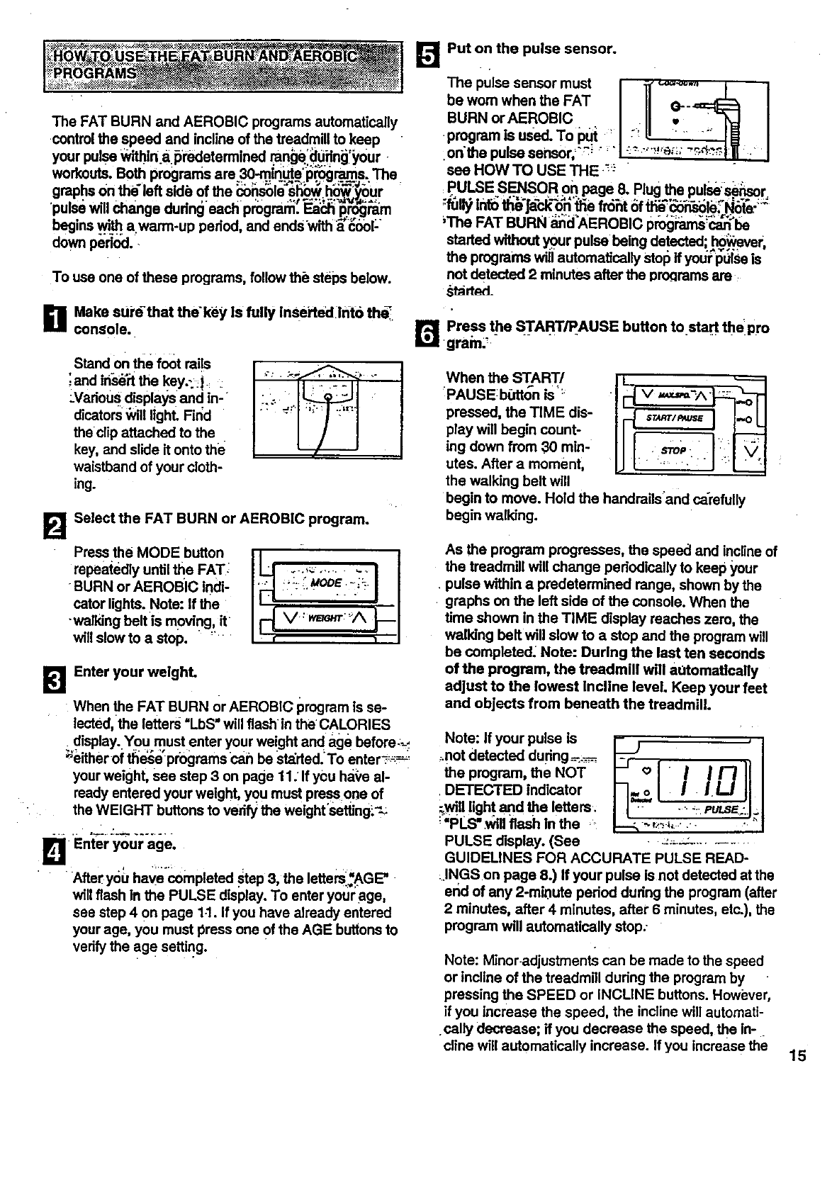
Put on the pulse sensor.
The pulse sensor must I "i1"..... I I
be worn when the FAT I II O--_ I
BURNor ROBIC I ,II •I
P" used'T°Pu :" .... I
onthe pulse sensor,=`_ "" I __' "_''_';;"_-_1 _""J
see HOW TO USE THE ,_;:"
PULSE S_SORon page 8. Plug the pulse:.s_=Pisor=
_The FAT BURN _d'AEROBIC pr_j_'be
started without your pulse being detected hB_ever ,
the programs wiil automatically Stol_if you|;puise is
not detected 2 minutes after the pr_rams are
started_
B Make surdthat the'key Is fully inserted]nto the.
console.
Stand on the foot rai!s
;and in-se'rtthe key.-:j.
:Vadous disPlaYs and in-
dicators_vill light. F'ir_d
theclip attached to the
key, and slide it onto the
waistband of your cloth-
ing.
B Select the FAT BURN or AEROBIC program.
repea{edly until the FAT; " --.,_-. .......
BURN or AEROBIC indi- :_:- _ooE-.;_.
catorlights. Note: If the " ' "":
willslow to a stop. " :
BEnter your welghL
When the FAT BURN or AEROBIC program is se-
lected, the letters =LbS"will flashin the CALORIES
; display..¥0U must enter your weight and age before;_:
_either of the_e programs can be Stdded.To enter_ =_,
your weight, see step 3 on page 11: If you ha_/eal-
ready entered your weight, you must press 0no of
the WEIGHT buttons to vedfy the weight'setting:._
DEnter your age.
After y0u havecompleted step 3, the letters_AGE"
will flash in the PULSE display. To enter your age,
see step 4 On page 1.1. If you have already entered
your age, you must press one Of the AGE buttons to
verify the age setting.
r_ Press the START/PAUSE button to start the pro
gram;_ - .......
When the START/
PAUSEbiJtton is'::
pressed, the TIME dis-
play will begin count-
ing down from 30 min-
utes. After a moment,
the walking belt will
begin to move. Hold the handrails'and carefully
begin walking.
As the program progresses, the speed and incline of
the treadmill will change pedodically to keep your
• pulse within a predetermined range, shown by the
graphs on the left side of the console. When the
time shown in the TIME display reaches zero, the
walking belt will slow to a stop and the program will
be completed: Note: During the last ten seconds
of the program, the treadmill will a,,tomattcally
adjust to the lowest Incline level. Keep your feet
and objects from beneath the treadmill.
Note: If your pulse is
:.notdetected dudng_-.-__-.
the program, the NOT
. DETECTED indicator
;,wil!light,and the letters.
' "PLS".wal flash in the .:
PULSE display. (See
I
k° II1-111
GUIDELINES FOR ACCURATE PULSE READ-
..INGS on page 8.) If your pulse is not detected at the
end of any 2-mit)ute period during the program (after
2 minutes, after 4 minutes, after 6 minutes, etc.), the
program will automatically stop;
Note: Minor.adjustments can be made to the speed
or incline of the treadmill during the program by
pressing the SPEED or INCLINE buttons. Howi_ver,
if you increase the speed, the incline will automati-
cally decrease; if you decrease the speed, the in-.
cline will automatically increase. If you increase the 15
incline, the speed will automatically decrease; if you
decrease the incline, the speed will automatically
increase. The conso/e wi/I a/ways attempt to keep
your pu/se near a predetermined se_'ng. When the
incline reaches the highest setting, the speed can-
not be decreased any further. When the incline
.re.a.ch.es_e Io_,e.stsetting, the speed cannot be
increased any further.
Note::To.stop .the pmgrarn temporarily, pre_ the
STA.RT/pAUS.E butto.n.:TheTIME display will begin
to flash. To restartthe program, press the
START/PAUSE buttonagain. The program will
resum.e.a_:lthe walking belt .wi'l!return to the !atest
speed setting. To terminate the program before the
program is completed, press the STOP button.
B FolI0w your progress with the five displays and
the TRAINING ZONE monitor.
See TRAINING ZONE MONITOR on.p_.ages.12 and
13
B When you are finished exerc!slng, stop the walk-
ing belt and remove the key.
To use the FITNESS TEST program, follow the steps
below.
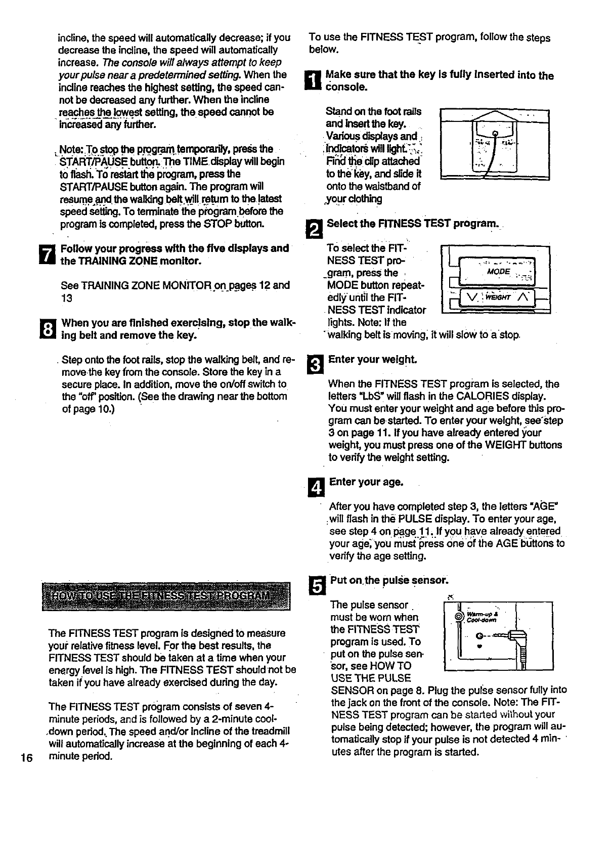
B Make sure that the key Is fully inserted into the
Console.
Stand on the foot rails
and insertthe key.
.Vado_ displays and
:lnd tors wi, ,ghL3" L
Finalt_e clip attached
to the key, and slide it
onto the waistband of
.your clothing
laTo Select the FIT-
NESS TEST pro-
_gram, press the =
MODE button repeat-
edly until the FIT-
NESS TEST indicator
lights. Note: If the
Select the RTNESS TEST program.•
^H
"walking belt is moving_ it will slow to astop,
•Step onto the foot rails, stop the walking belt, and re-
movethe key from the console. Store the key in a
secure place. In addition, move the on/off switch to
the "off" position. (See the drawing near the bottom
of page 10.)
BEnter your weight.
When the FITNESS TEST program is selected, the
letters "LbS" will flash in the CALORIES display.
You must enter your weight and age before this pro-
gram can be started. To enter your weight, see'step
3 on page 11. If you have already entered your
weight, you must press one of the WEIGHT buttons
to verify the weight setting.
B Enter your age.
•After you have completed step 3, the letters "AGE"
:will flash in the PULSE display. To enter your age,
see step 4 on page 11, If you have already entered
your age;you rnust_ress one of the AGE bL,tt0ns to
verify the age setting.
16
E!
The FITNESS TEST program is designed to measure
you# relative fitness level. For the best results, the
FITNESS TEST should be taken at a time when your
energy level is high. The FITNESS TEST shouldnot be
taken if you have already exercised dudng the day.
The FITNESS TEST program consists of seven 4-
minute periods, and is followed by a 2-minute cool-
.down period;The speed and/or incline of the treadmill
will automaflcally increase at the beginning of each 4-
minute period.
Put on.the pulse sensor.
The pulse sensor
must be worn when
the FITNESS TEST
program is used. To
put on the pulse sen.
sor, see HOW TO
USE THE PULSE
SENSOR on page 8. Plug the pulse sensor fully into
the jack on the front of the console. Note: The FIT-
NESS TEST program can be started without your
pulse being detected; however, the program will au-
tomatically stop if your pulse is not detected 4 min-
utes after the program is started.
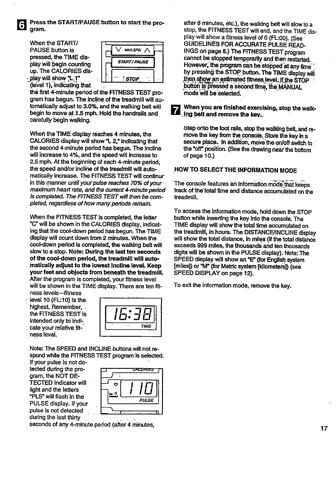
B Pressthe START/PAUSEbuttonto start the pro-
gram.
WhentheSTART/ i ;._l{
PAUSE button is V,Ax.sp_ /_
pressed, the TIME dis- I _START/PAUSSil
play will _egin counting
up. The CALORIES dis-
-p!aywillshow."L_!, "' !STOP _:1
_(level 1), indicating that
the first 4_minute period of the FITNESS TEST pro;
gram has begun. The incline of the treadmill will au-
tomatically adjust to 3.0%, and the walking belt will
•begin to move at:l.5 mPh.Hold the handrails and
carefully begin walking.
Whe_ the TIME display reaches 4 minutes, the
CALORIES display will show "L2," indicating that
the second 4-minute period has begun. The incline
will increas e to 4%, and the speed wil! increase to
2.5 mph. At the beginning of each 4-minute pedod,
•the speed and/or incline of the treadmill will auto-
matically increase. The FITNESS TEST will continur
in this nlanner untilyourpulse reaches 70% of your
maximum heart rate, and the current 4-minute period
is completed. The FITNESS TEST will then be com-
pleted, regardless of how many periods remain.
When the FITNESS TEST is completed, the letter
"C" will be shown in the CALORIES display, indicat-
ing that the cool-down period has begun. The TIME
display will count down from 2minutes. When the
cool-down pedod is completed, the walking belt will
slow to a stop. Note: During the last ten seconds
of the cool-dow]l period, the treadmill will auto-
matically adjust to the lowest incl!ne leve!. Keep
your feet and objects from beneath the treadmill.
After the program is completed, your fitness level
will be shown in the TIME display. There are ten fit-
ness levels---fitness
• level 10 (FL:IO) is the
the FITNESS TEST is IE"
IC/-
intended only to indi-
:cats your relative fit-
n.esslevel.
Note: The SPEED and INCLINE buttons will not re-
spond wh e the FITNESS TEST program is selected.
If your pulse is not de-
tected dudng the pro-
gram, the NOT DE-
TECTED indicator will
light and the letters
"PLS" will flash in the
PULSE display. If your
pulse is not detected : .
-J °[ I IFII
PULSE !
during the last thirty :.
seconds of any 4-minute period (after 4minutes,
after 8 minutes, etc.), the walking belt will slow to a
stop, the FITNESS TEST will end, and the TIME dis-
play will show a fitness level of 0 (FL:O0). (See
GUIDELINES FOR ACCURATE PULSE READ-
INGS on page 8.) The FITNESS TEST program
cannot be stopped temporodly and then restarted.
However,]be program can bestb_ped atany time"-
by pressing the STOP.button. Tile TIME d Spla_,wili
,_en show an ep_mated fitness leve. f.the STOP '
b_n Ls p_ a secondtime, the MANUAL
mode _vill be "selected. -....
When you are finished exercising, stop the walk-
;.B.m,_!ng =beltand remove the key._
_'tep onto the foot roils, stop the walking belt, and re-
move the key from the console_Stors the key ina
secure place.: In addition, move the on/off switchto
•the =off' position. (See the drawlng neat:the bottom
of page 10.)
.HOW TO SELECT THE INFORMATION MODE
The console features an informatior) rn_:_e=thatk_ps
track of the'total time and 'distance accumulated on the
treadmill.
To access the information mode, hold down the STOP
button while inserting the key into the console. The
TIME display will show the total time accumulated on
the treadmill, in hours. The DISTANCE/INCLINE display
will show the total distance, in miles ('ifthe total distance
exceeds 999 miles, the thoucands and ten thousands
digits will be shown in the PULSE display). Note: The
SPEED display will show an "E" (for English system
[miles]) or "M" (for Metdc system [kilometers]) (see
SPEED DISPLAY on page 12).
To exit the information mode, remove the key.
17
HOW TO FOLD AND MOVE THE TREADMILL
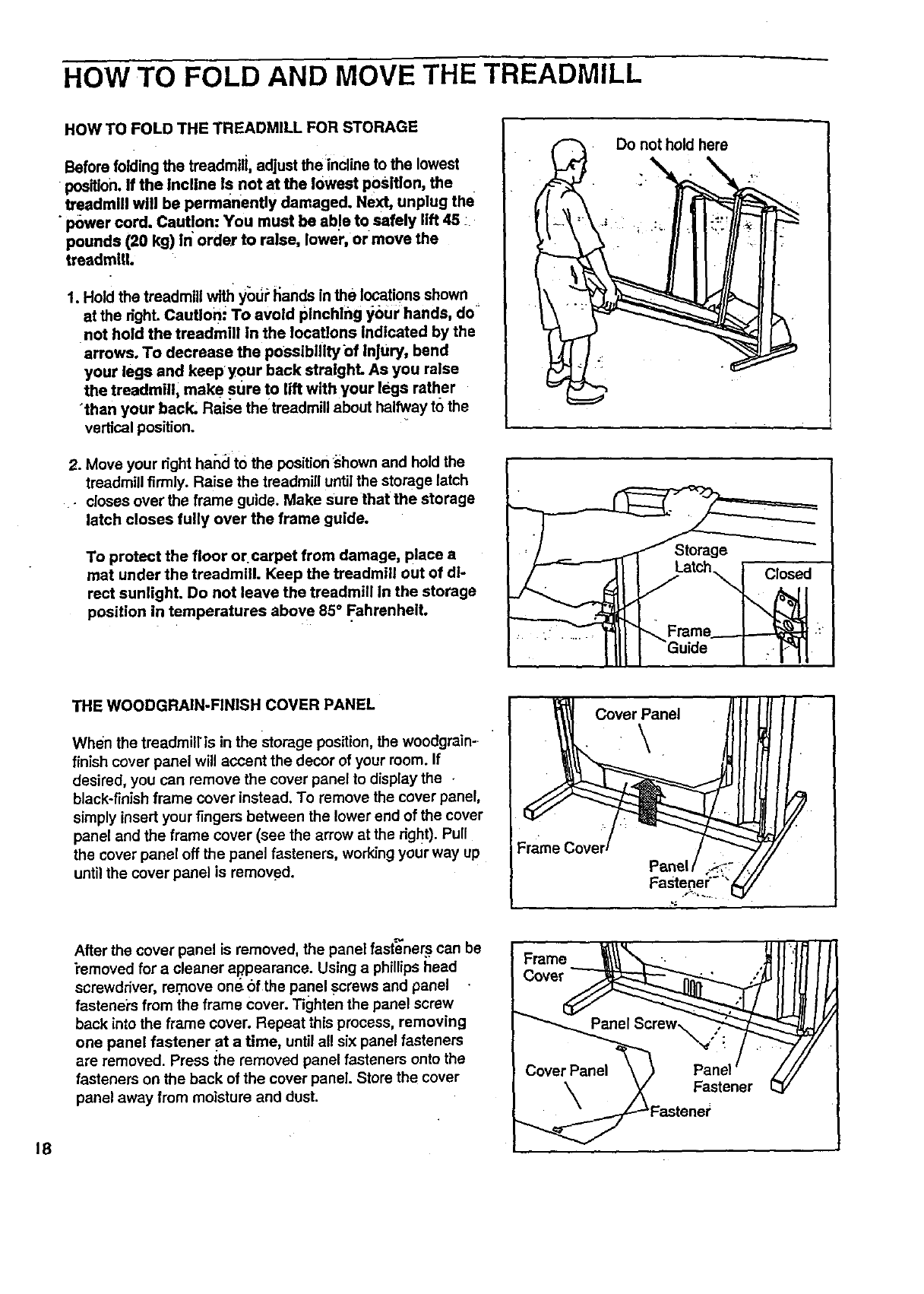
HOW TO FOLD THE TREADMILL FOR STORAGE
Before folding the treadmill, adjust the incline to the lowest
•position. If the incline Is not at the lowest position, the
traadmlll will be permanently damaged. Next, unplug the
• power cord. Caut!on: You must be ab!e to safely lift 45 :
pounds (20 kg) in order to raise, lower, or move the
treadmlU.
1. Hold the treadmill with y'odPI_ands in the locations shown
at the dghL caution.; To avoid pinchlng your hands, do
not hold the treadmill In the locations Indicated by the
arrows. To decrease the possibility of Injury, bend
your legs and keepyour back straight. As you raise
the treadmill, make stJre to lift with your legs ratl_er
"than your back. Raise the treadmill about halfway to the
vertical position.
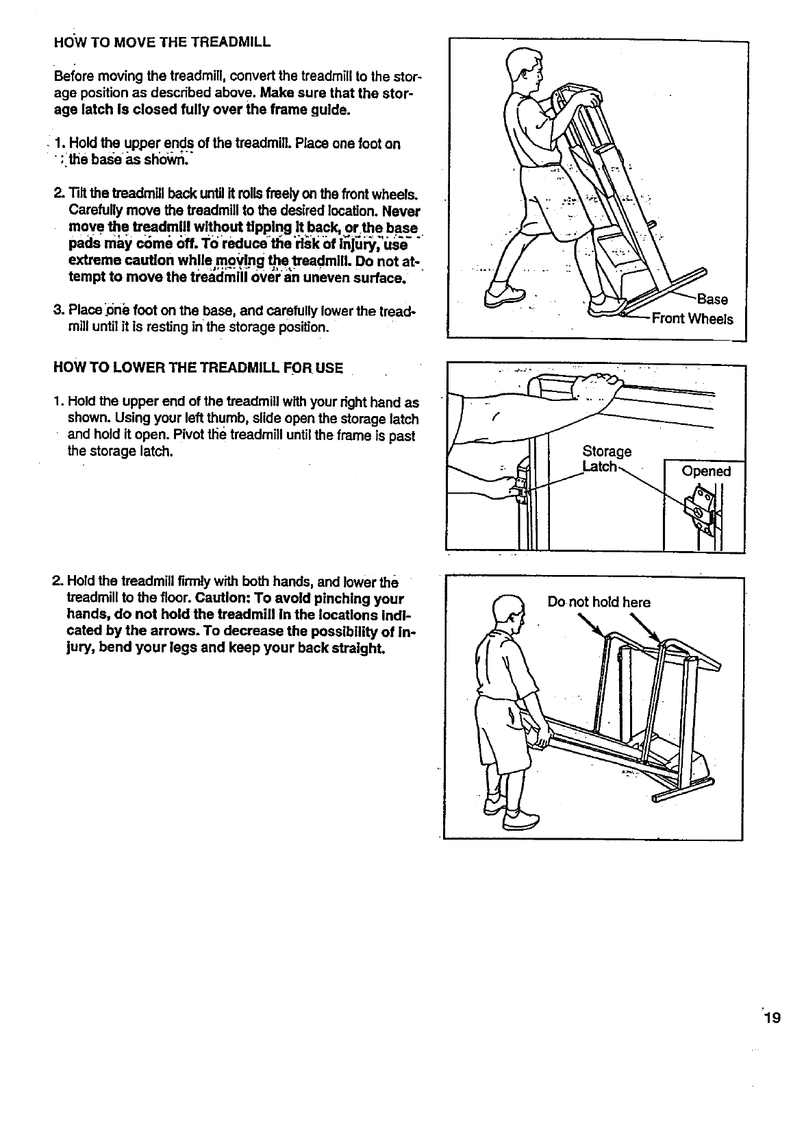
2. Move your right hand tO the positionshown and hold the
treadmill firmly. Raise the treadmill until the storage latch
• closes over the frame guide. Make sure that the storage
latch closes fully over the frame guide.
To protect the floor or carpet from damage, place a
mat under the treadmill. Keep the treadmill out of di-
rect sunlight. Do not leave the treadmill In the storage
position in temperatures above 85 °Fahrenheit.
Do not hold here ,
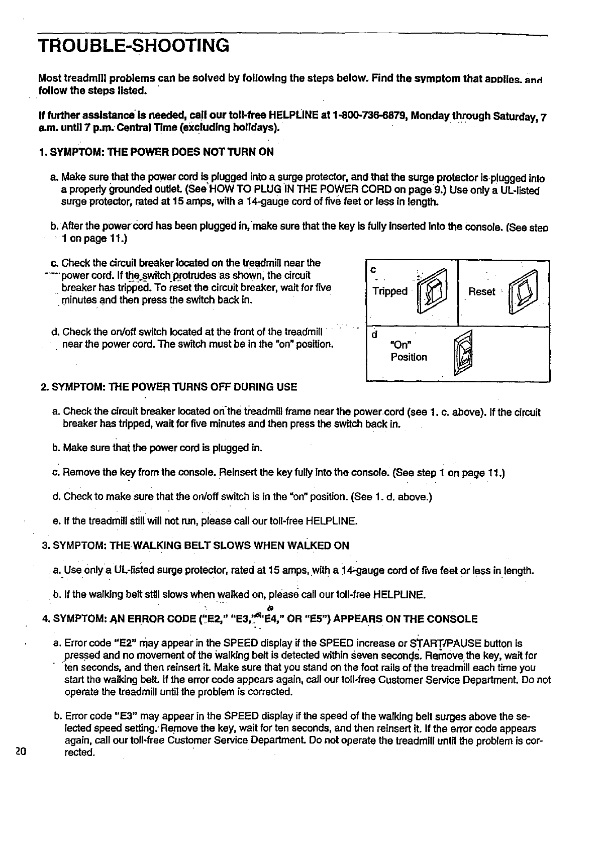
THE WOODGRAIN-FINISH COVER PANEL
When the treadmillis in the storage position, the woodgrain-
finish cover panel will accent the decor of your room. If
desired, you can remove the cover panel to display the
black-finish frame cover instead. To remove the cover panel,
simply insert your fingers between the lower end of the cover
panel and the frame cover (see the arrow at the right). Pull
the cover panel off the panel fasteners, working your way up
until the cover panel is removed.
Cover Panel
18
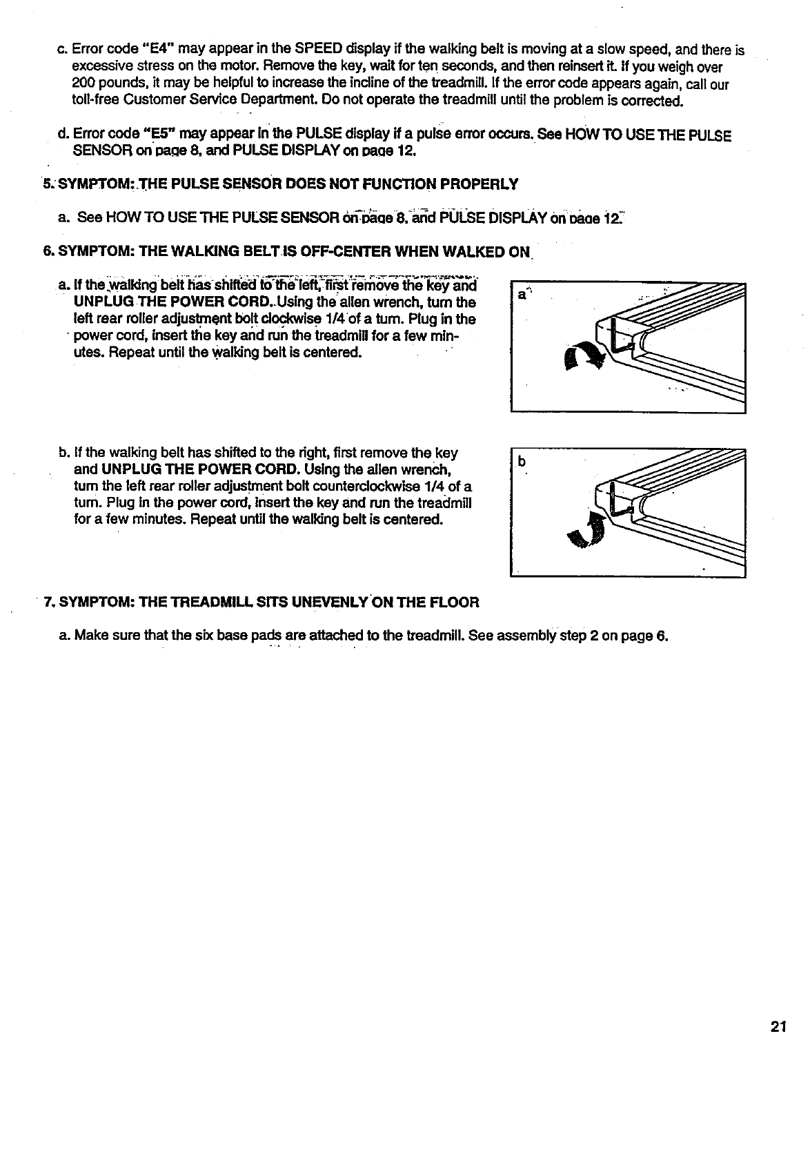
After the cover panel is removed, the panel fasteners can be
i'emoved for a cleaner al_pearance. Using a phillips head
screwdriver, remove one-bfthe Panel screws and panel
fasteners from the frame cover. Tighten the panel screw
back into the frame cover. Repeat this process, removing
one panel fastener at a time, until all six panel fasteners
are removed• Press the removed panel fasteners onto the
fasteners on the back of the cover panel. Store the cover
panel away from moisture and dust.
Cover_
_eWX, pa_PanelScrew /
_Fastener
Fastener
HOWTOMOVETHETREADMILL
Beforemovingthetreadmill,convertthetreadmillto thestor-
agepositionasdescribedabove.Makesurethatthestor-
agelatchis closedfullyovertheframe guide.
:1. Hold the upper ends of the treadmill. Place one foot on
;ithe base as sho_'n_"
2. Tilt the treadmill back untilit roils freely on the front wheels.
Carefully move the treadmill to the desired location. Never
move the treadmill without tipping It back, or the base
pads mJ_, c_me off. To reduce _e'rl_l_ of Inju_i_'us;_-
extreme caution while moving the treadmill. Do not at-
tempt to move the tre_cJmilJ0v_J"_n uneven surface.
3. Place _onefoot on the base, and carefully lower the tread-
mill until it is resting in the storage position.
Base
eels
HOW TO LOWER THE TREADMILL FOR USE
1. Hold the upper end of the treadmill with your right hand as
shown. Using your left thumb, slide open the storage latch
and hold it open. Pivot the treadmill untilthe frame is past
the storage latch. Storage
Latch_
2. Hold the treadmill firmly with both hands, and lower the
treadmill to the floor. Caution: To avoid pinching your
hands, do not hold the treadmill In the locations Indi-
cated by the arrows. To decrease the possibility of in-
jury, bend your legs and keep your back stralghL
Do not hold here
"19
TROUBLE-SHOOTING
Z0
Most treadmill problems can be solved by following the steps below. Find the symptom that aoolies. _nd
follow the steps listed.
If further asslstanca is needed, ca!l our toll-free HELPLINE at 1-800-736-6879, Monday through Saturday, 7
e.m. until 7 p.m. Central Time (exclud|ng holidays).
1. SYMPTOM: THE POWER DOES NOT TURN ON
a. Make sure that the power cord Is plugged into a surge protector, and that the surge protector isplugged into
a properly grounded outleL (See HOW TO PLUG IN THE POWER CORD on page9.) Use only a UL-listed
surge protector, rated at 15 amps, with a14-gauge cord of five feet or less in length.
b. After the powercord has been plugged in, make sure that the key is fully Inserted Into the console. (See steo
1 on page 11.)
c. Check the circuit breaker located on the treadmill near the
..... power cord. If _e switch protrudes as shown, the circuit
breaker has tripped. To reset the circuit breaker, wait for five
•minutes and then press the switch back in. c.
Tripped Reset
d. Check the on/off switch located at the front of the treadmill : " " d
near the power cord. The switch must be in the =on"position.
2. SYMPTOM: THE POWER TURNS OFF DURING USE
On 41
Position _l
a. Check the circuit breaker located on-the beadmill frame near the power cord (see 1. c. above). If the circuit
breaker has _pped, walt for five minutes and then press the switch back in.
b. Make sure that the power cord is plugged in.
cl Remove the key from the console. Reinsert the key fully into the console. (See step 1 on page 11.)
d. Check to make sure that the on/off switch is in the =on" position. (See 1. d. above.)
e. If the treadmill still will not run, please call our toll-free HELPLINE.
3. SYMPTOM: THE WALKING BELT SLOWS WHEN WALKED ON
a. Use 0nlya UL-listed surge protector, rated at 15 stops, with a _14_auge cord of five feet or less in length.
b. If the walking belt still slows when walked on, please call our toll-free HELPLINE.
II ,2 u _I_1 ii i# J_
4. SYMPTOM: ._N ERROR CODE ( E2, E3, E4, OR E5 ) APPEARS ON THE CONSOLE
a. Error code "E2" may appear in the SPEED display if the SPEED increase or START4PAUSE button is
pressed and no movement of the Walking belt is detected within seven seconds. Rernove the key, wait for
ten seconds, and then reinsert it. Make sure that you stand on the foot roils of the treadmill each time you
start the walking belt. If the error code appears again, call our toll-froe Customer Service Department. Do not
operate the treadmill until the problem is corrected.
b. Error code "E3" may appear in the SPEED display if the speed of the walking belt surges above the se-
lected speed setting. Remove the key, wait for ten seconds, and then reinsert it. It the error code appears
again, call our toll-free Customer Service Department. Do not operate the treadmill until the problem is cor-
rected.
c.Errorcode"E4" may appear in the SPEED display if the walking belt is moving at a slow speed, and there is
excessive stress on the motor. Remove the key, wait for ten seconds, and then reinsert it. ff you weigh over
200 pounds, it may be helpful to increase the incline of the treadmill. If the error code appears again, call our
toll*free Customer Service Department. Do not operate the treadmill until the problem is corrected.
d. Error code "E5" may appear Inthe PULSE display if a pulse error occurs. See HOW TO USE THE PULSE
SENSOR on Da_cle8, and PULSE DISPLAY on Daae 12.
5. SYMPTOM::I_E PULSE SENSOR DOES NOT FUNCTION PROPERLY
a. See HOW TO USE THE PULSE SENSOR on-_ee 8i_lr_d POLSE DISPLAY onoaae i2_!
6. SYMPTOM: THE WALKING BELT.IS OFF-CENTER WHEN WALKED ON.
a. If the _walldng:beit _-shiffe_ t_-th_leR,--fl_t '_en__ve _th_"k_6_'a'n'cl"
UNPLUG THE POWER CORD..Using the allen wl'ench, tum the
left mar roller adjustment bo!t clockwise 1/4 of a tum. Plug in the
power cord, insert the key and run the treadmill for afew min-
utes. Repeat until the .walking belt is centered.
b. If the walking belt has shifted to the dght, first remove the key
and UNPLUG THE POWER CORD. Using the allen wrench,
tum the left rear roller adjustment belt counterclockwise 1/4 of a
turn. Plug in the power cord, insert the kay and run the treadmill
for afew minutes. Repeat until the walking belt is centered.
b
"7. SYMPTOM: THE TREADMILL SITS UNEVENLY'ON THE FLOOR
a. Make sure that the six base pads are attached to the treadmill. See assembly step 2 on page 6.
21
CONDITIONING GUIDELINES
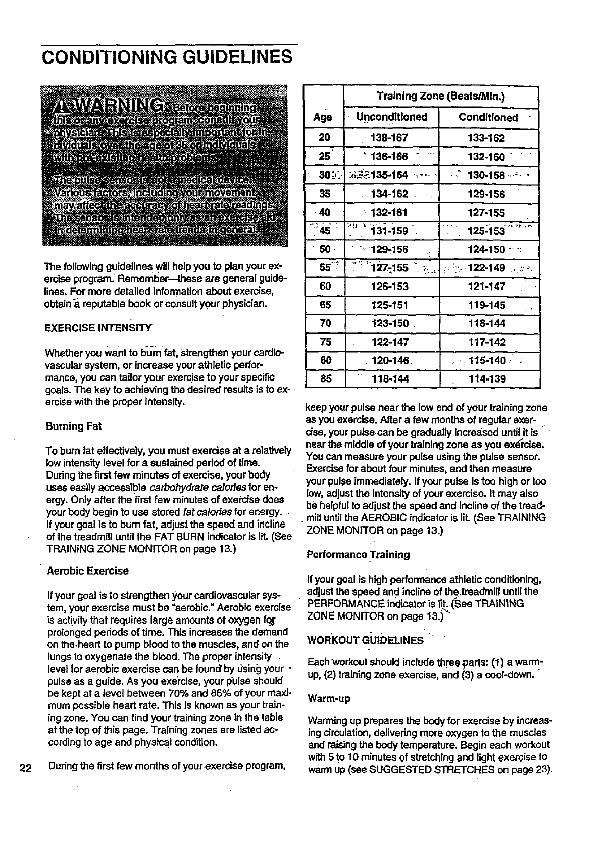
The following guideline s will help you to plan your ex-
e'rclseprogram. Remember -thase are general guide:
lines. For more detailed information about exercise,
obtain areputable book or consult your physician.
EXERCISE INTENSITY
Whether you want to bu_mfat, strengthen your cardio-
vascular system, or increase your athletic perfor-
mance, you can tailor your exercise to your specific
goals. The key to achieving the desired results is to ex-
emise with the proper intensity.
Burning Fat
To bum fat effectively, you must exercise at a relatively
low intensity level for a sustained pedod of time.
During the first few minutes of exercise, your body
uses easily accessible carbohydrate calories for en-
ergy. Only after the first few minutes of exePcise does
your body begin to use stored fat calories for energy.
If your goal is to bum fat, adjust the speed and incline
of the treadmill until the FAT BURN indicator is lit. (See
TRAINING ZONE MONITOR on page 13.)
Aerobic Exercise
If your goal is to strengthen your cardiovascular sys-
tem, your exercise must be "aerobic." Aerobic exercise
is activity that requires large amounts of oxygen f_
prolonged periods of time. This increases the demand
on the.heart to pump blood to the muscles, and on the
lungs to oxygenate the blood. The proper intensity .
level for aerobic exercise can be found'by dsing your •
pulse as a guide. As you exercise, your pulse should
be kept at a level between 70% and 85% of your maxi-
mum possible heart rate. This is known as your train-
ing zone. You can find your training zone in the table
at the top of this page. Training zones are listed ac-
cording to age and physical condition.
22 Dudng the first few months of your exercise program,
Age
20
25"
• "30 :_..
35
40
•50.
"5,,5-_?.
60
70
75
80
85
Training Zone (Beats/MIn.)
Urlcondltloned Conditioned -
138-167 133-162
• 136-166 " "132-160 " " "
:,_.--';_135-154 ........ " 136-158 ......
.134-162 129-156
132-161 127-155
:'_'_:_;131-i59 ". 1i' 125_i53
•_129-156 : 124-150 " :
'127-155 ;...-- ;_- 122-149 .;_-_.
126-153
125-151
123-150 .
122-147
126-146
""118-144
121-147
119-145
118-144
117-142
116-140 .-i .._
114-139
keep your pulse near the low end of your training zone
as you exercise. After a few months of regular exer-
cise, your pulsecan be gradually increa_seduntil it Is
near the middle of your training zone as you exercise.
You can measure your pulse usingthe pulse sensor.
Exercise for about four minutes, and then measure
your pulse immediately. If your pulse is too high or too
low, adjust the intensity of your exercise. It may also
be helpful to adjust the speed and incline of the tread-
. mill untitthe AEROBIC indicator is lit. (See TRAINING
ZONE MONITOR on page 13.)
Performance Training
If your goal is high performance athletic conditioning,
adjust the speed and incline of the,treadmill untilthe
PERFORMANCE inclicatoris tit. Gee TRAINING
ZONE MONITOR on page 13.)"'
WORI(OUT GUIDELINES "
Each workout should include three ..pads:(1) a warm-
up, (2) training zone exercise, and (3) a cool-down.
Warm-up
Warming up prepares the body for exercise by increas-
ing circulation, delivering more oxygen to the muscles
and raising the body temperature. Begin each workout
with 5 to 10 minutes of stretching and light exercise to
warm up (see SUGGESTED STRETCHES on page 23).
Training Zone Exercise
After warming up, increase the intensity of your exer-
cise until your pulse is in your training zone for 20 to
60 minutes. (Dudng the first few weeks of your exer-
cise program, do not keep your pulse in your training
zone for Ionq_r than 20 minutes.) Breathe regularly
and deeply as _,Ouexemtse--ne_ier hold your breath.
Cool-down
Rnish each Workout with 5 to 10 minutes of stretching
to cool down._This will increase the flexibility of your
muscles and will help to prevent post-exercise problems.
Exercise Frequency
To maintain or improve your condition, complete three
•workouts each week, with at least one day of rest be-
...;twean workouts. After a few months, you may com-
plete up to five workouts each week if desired.
•' Ine Key to success is to make exercise a regular and
enjoyable part of your everyday life.
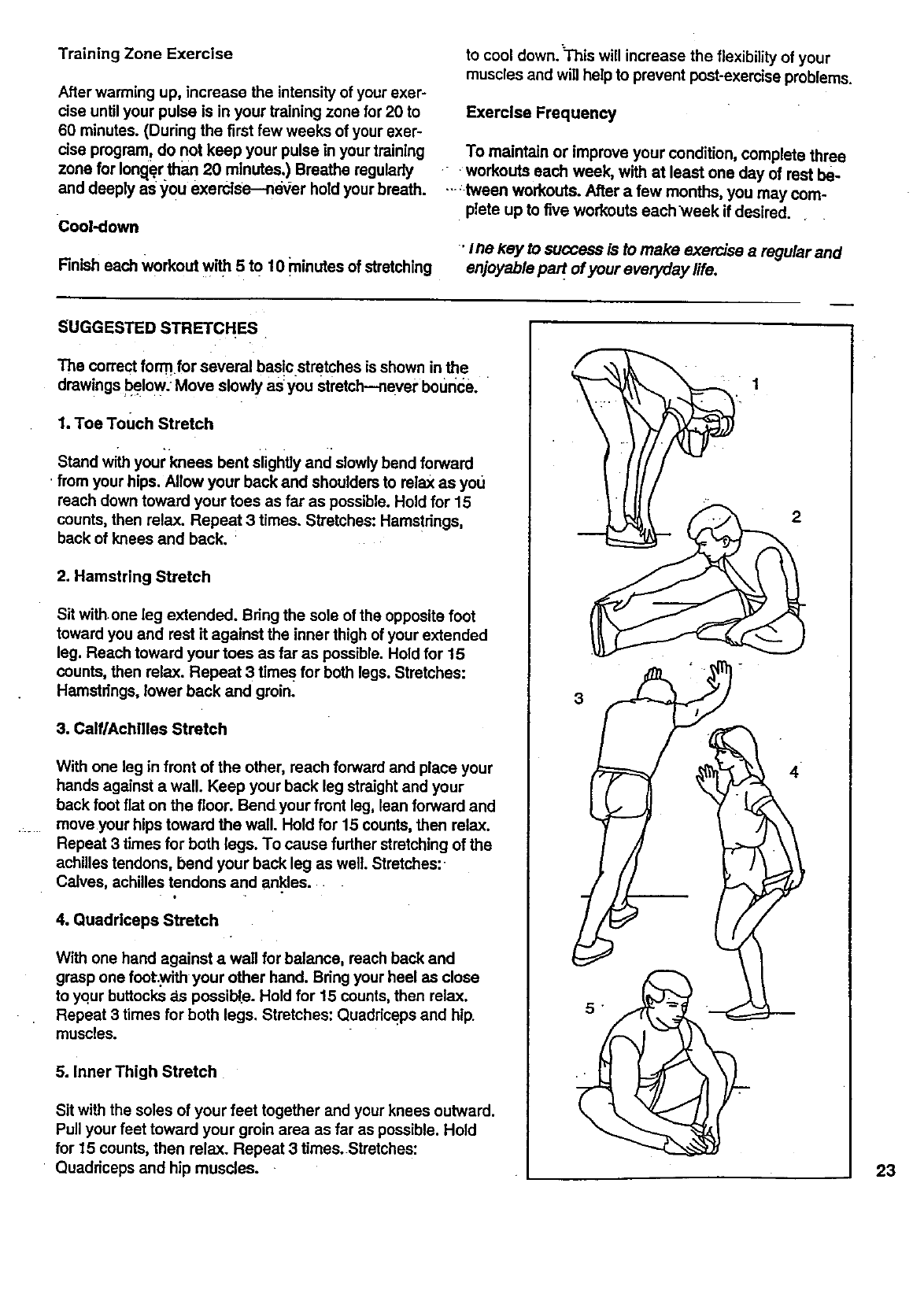
SUGGESTED STRETCHES
The correct form for several basic stretches is shown in the
drawings below. Move slowly as you stretch--neyer bounce.
1. Toe Touch Stretch
Stand with your knees bent Slightlyand slowly bend forward
from your hips. Allow your back and shoulders to relax as you
reach down toward your toes as far as possible. Hold for 15
counts, then relax. Repeat 3 times. Stretches: Hamstdngs,
back of knees and back.
2. Hamstring Stretch
Sit withone leg extended. Bdng the sole of the opposite foot
toward you and rest it against the inner thigh of your extended
leg. Reach toward your toes as far as possible. Hold for 15
counts, then relax. Repeat 3times for both legs. Stretches:
Hamstrings, lower back and groin_
3. CalflAchllles Stretch
With one leg in front of the other, reach forward and place your
hands against a wall. Keep your back leg straight and your
back foot fiat on the floor. Bend your front leg, lean forward and
move your hips toward the wall. Hold for 15 counts, then relax.
Repeat 3times for both legs. To cause further stretching of the
achilles tendons, bend your back leg as well. Stretches:
Calves, achilles tendons and ankles.
0
4. Quadriceps Stretch
With one hand against awall for balance, reach back and
grasp one fcot.with your other hand. Bdng your heel as close
to your buttocks _Lspossible. Hold for 15 counts, then relax.
Repeat 3 times for both legs. Stretches: Quaddceps and hip.
muscles.
5. Inner Thigh Stretch
Sit with the soles of your feet together and your knees outward.
Pull your feet toward your groin area as far as possible. Hold
for 15 counts, then relax. Repeat 3 times. Stretches:
• Quaddceps and hip muscles.
3
2
4
23

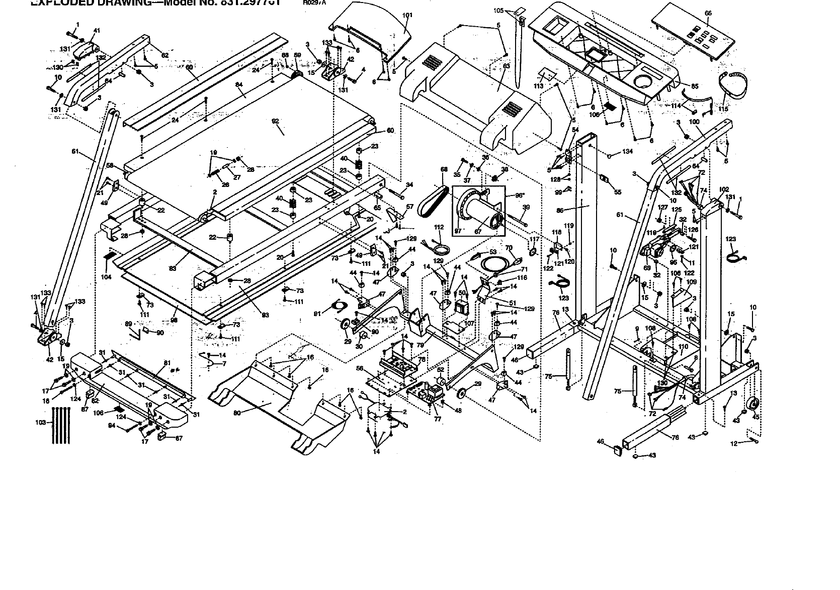
Note:Specificationsaresubjecttochangewithoutnotice.Forinformationabout
orderingreplacementparts,seethebackcoveroftheUser's Manual.
141
131
2
\
1114
-tliii ,,
131
16
14
34
112
77
_134
3\
5
10
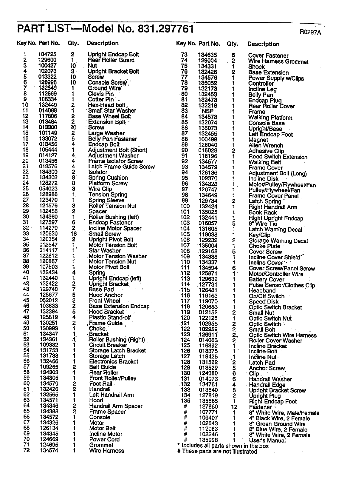
PART LISTmModel No. 831.297761 R02gTA
Key No. Part No. Qty. Description
1 104725
2 129600
3 100427
4 102073
5 013322
6 126996
7 132549
8 112669
9 .106334
10 132449
11 014088
12 117806
13 013484
14 013300
15 101149
16 133072
17 013456
18 105444
19 014127
20 013456
21 013576
22 134300
23 134302
24 128272
25 054023
26 128986
27 123470
28 121576
29 132456
30 134360
31 127597
32 114270
33 120630
34 120354
35 013547
36 014117
37 122812
38 120867
39 107503
40 132434
41 132440
42 132422
43 129740
44 125677
45 052012
46 103833
47 132394
48 125819
49 130251
50 130993
51 134347
52 134361
53 109382
54 131753
55 131738
56 132466
57 109265
68 .134303
59 134305
60 134570
61 132426
62 132565
63 134571
64 134346
65 134388
66 134572
67 134326
68 126134
69 134345
7O 124669
71 124695
72 134574
2Upright Endcap Bolt
1 Rear Roller Guard
E0 Nut
3 Upright Bracket Bolt
IO Screw
1O ConsoleScrew :'
1 Ground Wlre':'
1 Clevis Pin "
1Cotter Pin' ..
2 Hex-Head bolt,
1•Small Star Washer
2 Base Wheel Bolt
2'Extension.Bo!t-
_-(_ •Screw .
2Large Washer
5 Belly Pan Fastener
4 Endcap Bolt .
1 Adjustment Bolt (Short)
4 Adjustment Washer
4 Frame Isolator Screw
4 Latch Frame Guide Screw
2Isolator
8 Spdng Cushion
8 Platform Screw
3Wire Clip
1 Tension Spdng
1 Spring Sleeve
3 Roller Tension Nut
2 Spacer
1 Roller Bushing(left)
6 Endcap Fastener
2 Incline Motor Spacer
18 Small Screw
2 Updght Pivot Bolt
1 Motor•TensionBolt
1' Star Washer
1 MotorTension'Washer
1 MotorTension Nut•
1 Motor Pivot Bolt
4 Spdng ,
1 Updght Endcap (left)
2•Updght Bracket
7 Base Pad ,
5 Hood Anchor
2FrontWheel
2 Base Extension Endcap
5 Hood Bracket.
4 Plastic Stand-off
2iFrame Guide
1 Choke,
1. ,Bracket
.1! •RollerBushing(Right)
1 C roiJlt Breaker•
1 Storage Latch Bracket
1 Storage Latch
1 ElectronicsBracket
2 BeltGuide
•.1 Rear Roller
1 FrontRoller/Pulley
2 Foot Rail
•2 Handrail
1 Left Handrail Arm
1 Hood
2 Handrail Arm Spacer
2 Frame Spacer
1 Console
1 Motor
1 Motor Belt
1 Incline Motor
1 Power Cord
1 Grommet
1 Wire Harness
Key No. Part No. Qty. Description
•73 134635 6 Cover Fastener
74 129004 2 Wire Hamess Grommet
75 134331 1 Shock
76 132426 2 Base Extension
77 134576 1 Power Supply w/Clips
78 135052 1 Controller
79 132173 1 Incline Leg
80 132453 1 Belly Pan
81 132473 1 Endcap Plug
82 132218 1 Rear Roller Cover
83 NSP 1 Frame
84 134578 1 Walking Platform
.85 .132074 1 Console Base
86 136073 1 Updght/Base . -
87 132455 1 Laft Endcap Foot
88 100498 1 Magnet
69 126040 1 Allen Wrench
90 016028 2 Adhesive Clip
91 118196 1 Reed Switch Extension
92 134577 1 Walking Belt
93 134579 1 Frame Cover
94 .126136 1 Adjustment Bolt (Long)
95 109370 1 Incline Disk
96 134328 1. Motor/Pulley/Flywheel/Fan
97 126747 1 Pulley/Flywheel/Fan
98 134649 1 Frame Cover Panel.
99 129734 2 Latch Spring
100 132424 1 Right Handrail Arm
101 135025 1 Book Rack
102 132441 1 Right Updght Endcap
103 016057 5 8"Wire Tie
104 131605 1 Latch Warning Decal
105 119038 1 Key/Clip
106 129232 2 Storage Warning Decal
107 '135004 1Choke Plate •
108 .129168 5 Cover Screw
109 134338 1 Incline Cover Shield"
110 134337 1 Incline Cover-', "
111 134594 6 Cover Screw/Panel Screw
,112 125871 1 "Motor/Controller Wire
113 129639 1 Battery Cover
114 127731 1 Pulse Sensor/Clothes €lip
•115 126481 1 Headband
116 119163 1 On/Off Switch •
117 119070 1 Speed Disk
118 I-20653 1 Optic Switch Bracket
119 012152 2 Small Nut
120 122125 1 Optic Switch Nut
.121 102955 2 Optic Switch :
122 102959 2 Small Bolt •
123 126911 2. Optic SwitchWire Harness
124 014063 2 Roller CoverWasher
125 116892 1 Incline-Bracket
126 013375 t " Incline-Bolt
127 119425 .1 Ir_line Nut-
128 131562 2 Latch Pad
129 013529 5 Anchor Screw
130 124380 6 .Clip ,. "..,'_
1.31 014073 6 Handrail Washer
.132 1"34761 4 Handrail Edge
133 013540 8 Upright Bracket Screw
134 127819 2 Updght Plug
135 135665 1 Right Endcap Foot
#127860 12 Fastener : "
#107771 1 8" White Wire, Male/Female
#109407 1 4" Black Wire, 2 Female
#102643 1 8" Green Ground Wire
'#112083 1 8" Blue Wire, 2 Female
#102246 1 8" White Wire, 2 Female
#135998 1 User's Manual
*Includes all parts shown in the box
-# These partsare not illustrated
SmARS
Model No. 831.297761
QUESTIONS?
if you find that-
• you need help assembling or
. operating the PROFORI_P_725__
TL treadmill
•a part is missing
•or you need to schedule repair
service
call our toll-free HELPLINE
1-800-736-6879
Monday-Saturday, 7 am-7 pm
Central Time (excluding holidays)
REPLACEMENT
PARTS
If parts become worn and need
to be replaced, call the following
toll-free number
1-800-FON-PART
(1-800-366-7278)
The model number and sedal number of your PROFoRM °725
treadmill are listed on a decal attached to the frame. See the front
cover of this manual to find the location of.the decal.
All replacement parts are available for Immediate purchase or=_ _
special order when you visit your nearest SEAR S Service Center.
To request service or to ofdar parts by telephone call the toll-free
numbers listed at the left.
,When requesting help or service, or ordering parts, please be pre
pared to provide the following information:
•The NAME OF THE PRODUCT (PROFORIVP 725 TL treadmill)
...,. ;- . . . . .
•The MODEL NUMBER OFTHE PRODUCT (831.297761)
"• The PART NUMBER OF THE PART (see the EXPLODED
•DRAWING and PART LIST included in this manual)
•_I'he.DESCRIPTIoN OFTHE PART (see the EXPLOD_-u uHAw-
ING and PART LiST included in this manual).
" : Part No. 135998 F04247AC R0297A Printed in USA © 1997 sears, Roebuckand Co.
