Proform 831297772 User Manual PRO FORM TREADMILL Manuals And Guides L9080021
PROFORM Treadmill Manual L9080021 PROFORM Treadmill Owner's Manual, PROFORM Treadmill installation guides
User Manual: Proform 831297772 831297772 PROFORM PRO-FORM TREADMILL - Manuals and Guides View the owners manual for your PROFORM PRO-FORM TREADMILL #831297772. Home:Fitness Equipment Parts:Proform Parts:Proform PRO-FORM TREADMILL Manual
Open the PDF directly: View PDF ![]() .
.
Page Count: 16
PRO.r-ORM
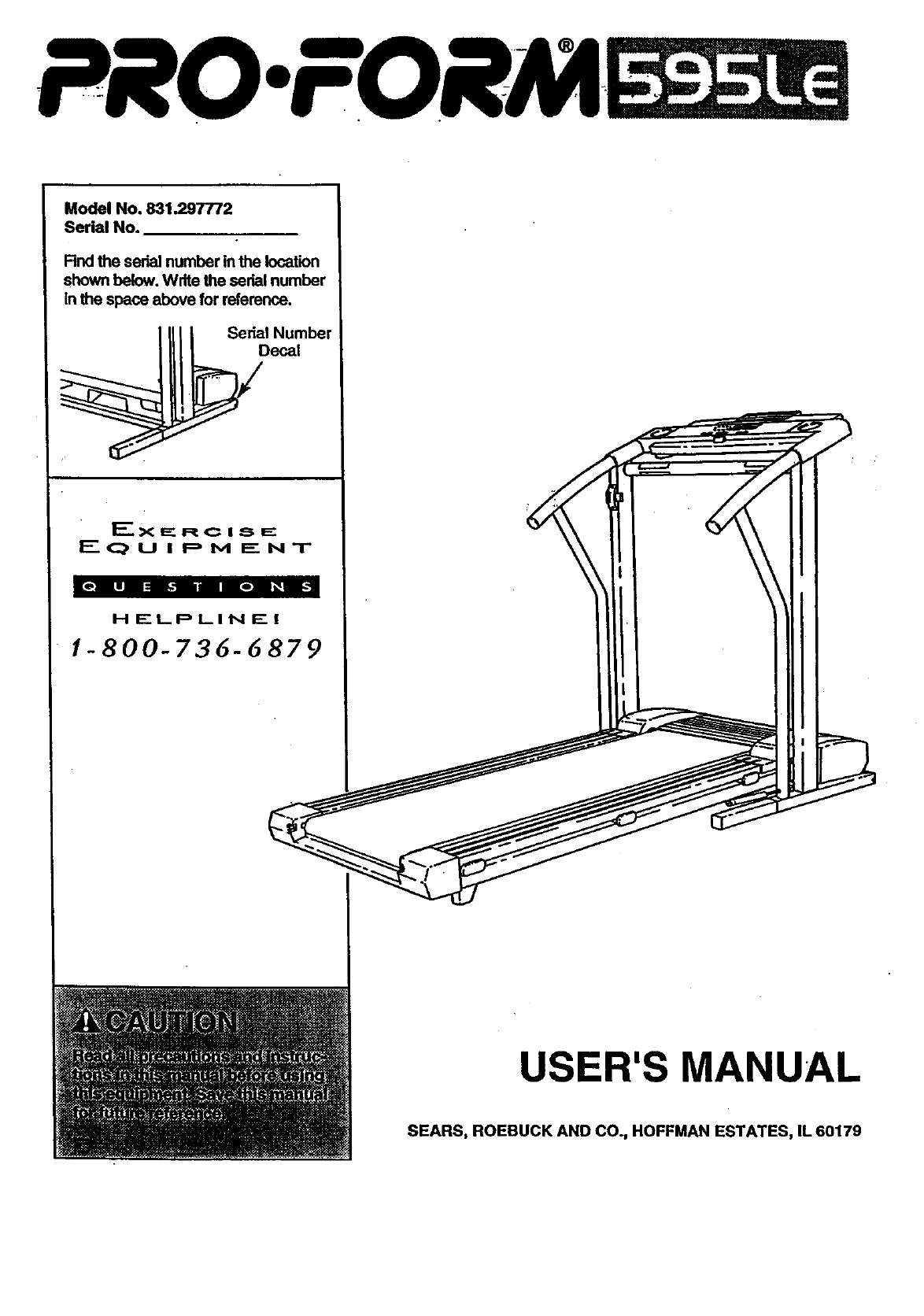
Model No. 831.297772
Serial No.
Rnd the serial number in the location
shown below. Write the serial number
in the space above for reference.
_____111 I Sedal Number
it F
EQUIPMENT
ionlilli|o|_12
H ELPLINI=" !
1-800-736-6879
USER'S MANUAL
SEARS, ROEBUCK AND CO., HOFFMAN ESTATES, IL 60179

TABLE OF CONTENTS
IMPORTANT PRECAUTIONS ................................................................. 2
BEFORE YOU BEGIN ...................................................................... .4
ASSEMBLY .......................................................• ,.......... .. • ..... ... • 5
OPERATION'AND'A'D'3USTMENT ..... "-.:= .'--.-_._-...-; ....... ................................... .7
HOWTO FOLD AND MOVE THE TREADMILL .................................................. 11
TROUBLE-SHOOTING ..................................................................... 12
CONDITIONING GUIDELINES ............................................................... 14
PART LIST ............................................................................... 15
ORDERING REPLACEMENT PARTS .................................................. Back Cover
FULL 90-DAY WARRANTY .......................................... ...... .. • ,.. .,. .o Back Cover
Note: An EXPLODED DRAWING is attached in the center of this manual.
IMPORTANT PRECAUTIONS
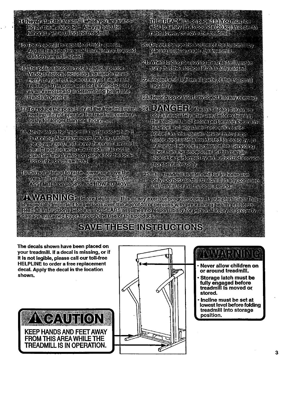
The decals shown have been placed on
your treadmill. If a decal is missing, or if
it is not legible, please call our toU-free
HELPLINE to order a free replacement
decal. Apply the decal in the location
shown.
KEEPHANDSANDFEETAWAY
FROMTHISAREAWHILETHE
TREADMILLISINOPERATION.
• Never allow children on
or around treadmill.
• Storage latch must be
fully engaged before
treadmill is moved or
stored,
•Incline must be set at
lowest level before folding
treadmill into storage
•position.
3
BEFORE YOU BEGIN
Thank you for selecting the new PROFORIVP 595LE Monday through Saturday, 7 a.m. until 7 p.m. Central
treadndlL The 595LE treadmill combines advanced Time (excluding holidays). To help us assist you,
technology with Innovetive design to let you enjoy an please note the product model number and sedal num-
. excellent form'-of__r exercise In the-esnve-. --ber before calling. The model number of the treadmill
nlence and privacy of your home. And when you're net Is 831,297772. The serial number can be found on a
exerdslng, the unique 595LE can be folded up, requir- decal 8ttached to the treadmill (see the front cover of
ing less than half the floor space of other treadmills, thIs manual for the location).
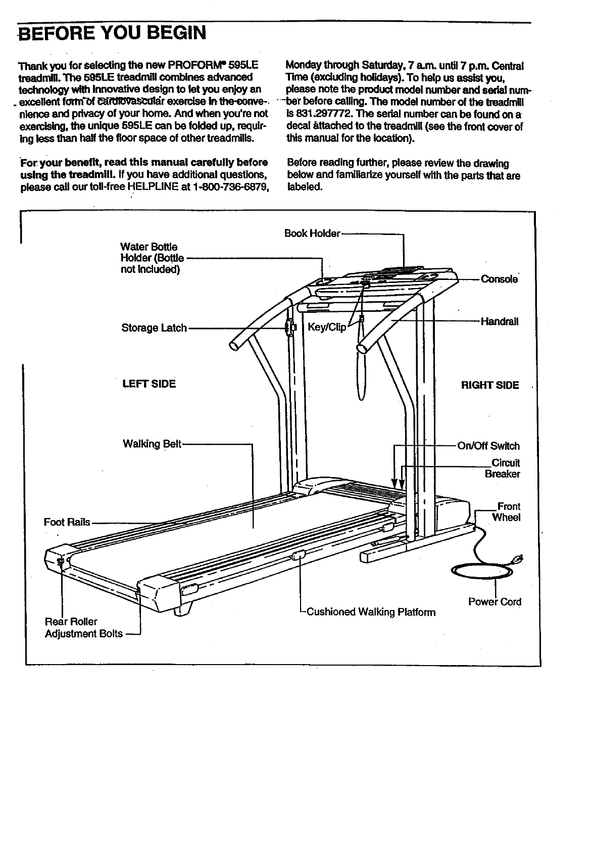
For your benefit, read this manual carefully before Before reading further, please review the drawing
using the treadmill. If you have additional questions, below and familiadze yourself with the pads that am
please call our toll-free HELPLINE at 1-800-736-6879, labeled.
IWater Bottle
Holder (Bottle
not Included)
Book Holder
Foot Rails
Storage Latch.
• LEFT SIDE
Walking Belt.
\ \ \
Handrail
RIGHT SIDE
Circuit
Breaker
Wheel
r Roller
Adjustment Bolts
Platform 'Cord
i
ASSEMBLY
Assembly requires tw_ people. Set the treadmill in a cleared area and remove all packing rnatedals. Do not .
dispose of the packing materials until assembly is completed. Assembly requires the Included ellen wrenc.._
and your own phillips screwdriver (_:_-==-,---, adjustable wrench _ and scissors
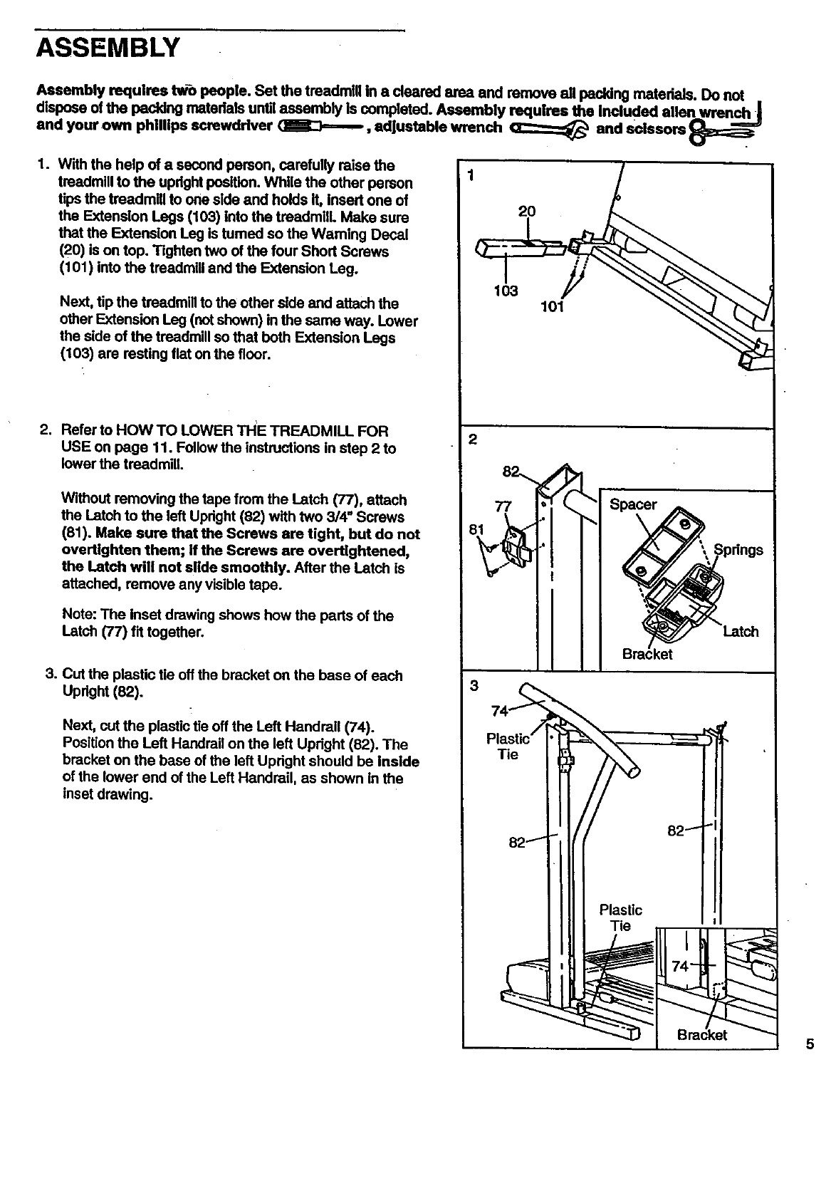
1. With the help of a second person, carefully raise the
treadmill to the updght position. While the other person
tips the treadmill to one side and holds It, Insert one of
the Extension Legs (103) into the tmadmllL Make sure
that the Extension Leg Is tumed so the Waming Decal
(20) is on top. Tighten two of the four Short Screws
(101) into the treadmill and the Extension Leg.
Next, tip the treadmill to the other side and attach the
other Extension Leg (not shown) in the same way. Lower
the side of the treadmill so that both Extension Legs
(103) are resting fiat on the floor.
2. Refer to HOWTO LOWER THE TREADMILL FOR
USE on page 11. Follow the instructions in step 2 to
lower the treadmill
Without removing the tape from the Latch (77), attach
the Latch to the left Upright (82) with two 3/4" Screws
(81). Make sure that the Screws ere tight, but do not
overtlghten them; ff the Screws are overtightened,
the Latch will not slide smoothly. After the Latch is
attached, remove any visible tape.
Note:The Insetdrawingshowshow the partsof the
Latch (77) f'dtogether.
3. Cut the plastic tie off the bracket on the base of each
Upright (82).
Next, cut the plastic tie off the Left Handrail (74).
Position the Left Handrail on the left Updght (82). The
bracket on the base of the left Upright should be Inside
of the lower end of the Left Handrail, as shown in the
inset drawing.
1
20
103 101
5
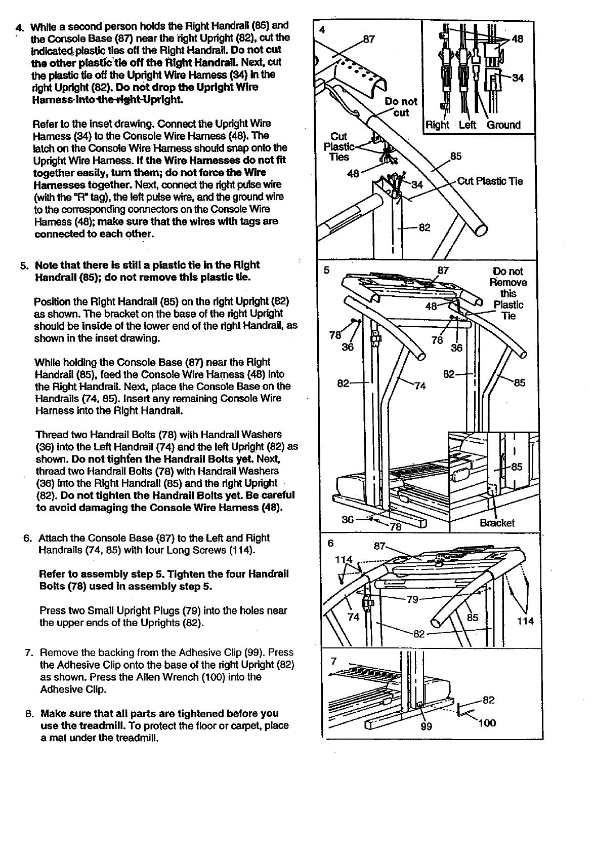
4. While asecond person holds the Right Handrail (85) and
the Console Base (87) near the dght Uptight (82), cut the
indicated.plestic ties off the Right Handrail. Do not cut
the other plastic'tle off the Right Handrail. Next, cut
the plastio tie off the UPdght Wire Harness (34) in the
right Upright (82), Do not drop the Upright Wire
Hamess.i_to _the-d_tJJprighL
Refer to the inset drawing. Connect the Updght Wire
Harness (34) to the Console Wire Harness (48). The
latch on the Console Wire Hamess should snap onto the
Updght Wire Hamess. ff the Wire Harnesses do not fit
together easily, turn them; do not force the Wire
Harnesses together. Next, connect the dght pulse wire
(with the _ tag), the left pulse wire, and the groundwire
to the corresponding connectors on the Console Wire
Harness (48); make sure that the wires with tags are
connected to each other.
5. Nots that there is still a plastic tie in the Right
Handrail (85); do not remove this plastic tie.
Position the Right Handrail (85) on the right Updght (82)
as shown. The bracket on the base of the dght Upright
should be inside of the lower end of the dght Handrail, as
shown in the inset drawing.
While holding the Console Base (87) near the Right
Handrail (85), feed the Console Wire Harness (48) into
the Right Handrail. Next, place the Console Base on the
Handrails (74, 85). Insert any remaining Console Wire
Harness into the Right Handrail.
Thread two Handrail Bolts (78) with Handrail Washers
(36) into the Left Handrail (74) and the left Updght (82) as
shown. Do not tigh(en the Handrail Bolts yet. Next,
thread two Handrail Bolts (78) with Handrail Washers
(36) into the Right Handrail (85) and the right Updght
(82). Do not tighten the Handrail Bolts yet. Be careful
to avoid damaging the Console Wire Harness (48).
6. Attach the Console Base (87) to the Left and Right
Handrails (74, 85) with four Long Screws (114).
Refer to assembly step 5. Tighten the four Handrail
Bolts (78) used in assembly step 5.
Press two Small Upright Plugs (79) into the holes near
the upper ends of the Uprights (82).
7. Remove the backing from the Adhesive Clip (99). Press
the Adhesive Clip onto the base of the right Upright (82)
as shown. Press the Allen Wrench (100) into the
Adhesive Clip.
8. Make sure that all parts are tightened before you
use the treadmill. To protect the floor or carpet, place
a mat under the treadmill.
Ground
- Cut Plastic Tie
87 Do not
Remove
this
Plastic
Tie
36
6 87_ =..,
99 100
OPERATION AND ADJUSTMENT
THE PERFORMANT LUBE TM WALKING BELT
Your traadmill features awalking belt coated with
PERFORMANT LUBE TM, a high-performance lubricant.
IMPORTANT: Never apply silicone spray or other
substances to the walking bolt or the walking plat-
form. Such substances will deteriorate the walking
belt and cause excessive wear.
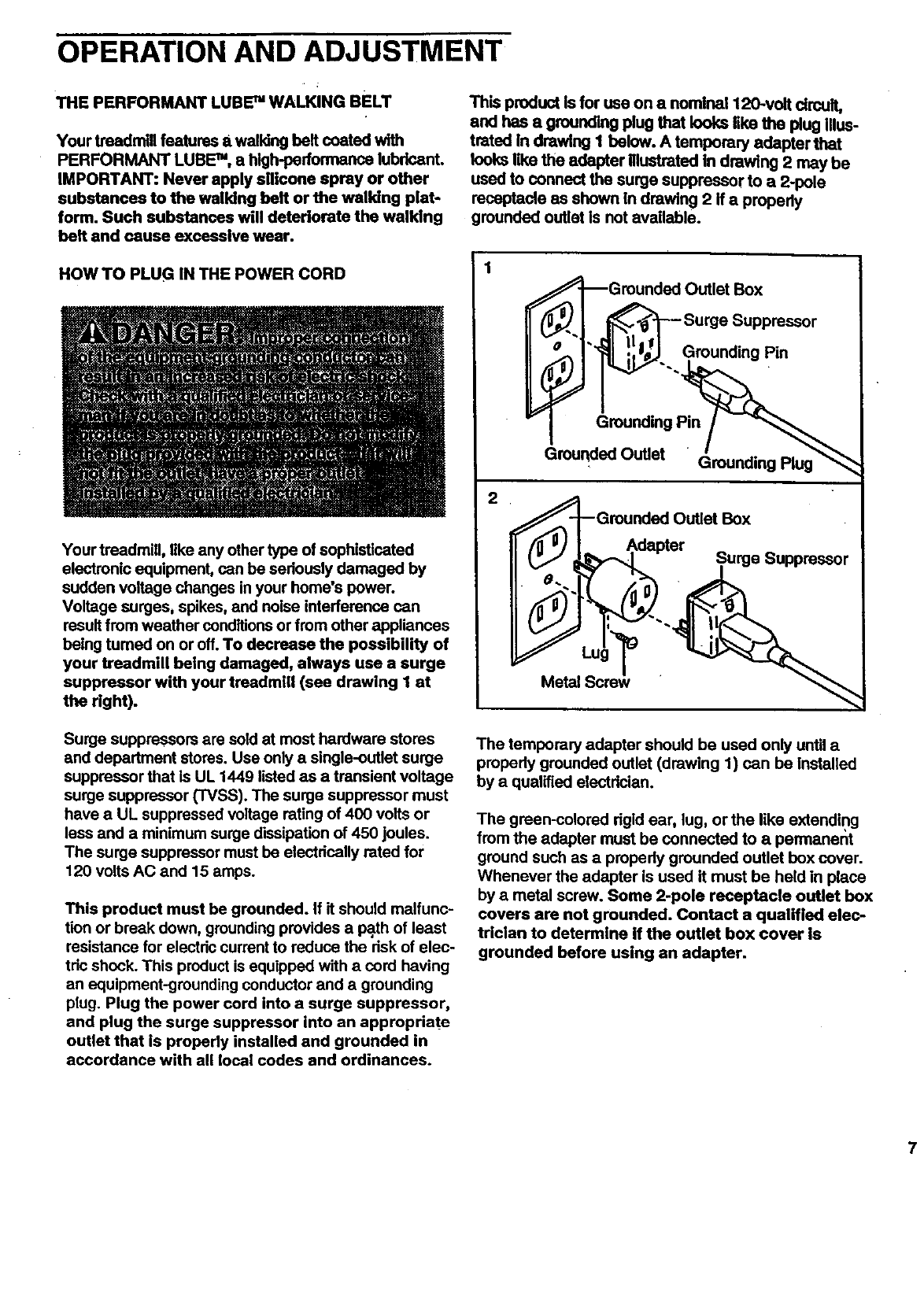
This product Is for use on a nornina1120-volt circuit,
and has a grounding plug that looks like the plug Illus-
trated In drawing I below. A temporary adapter that
looks like the adapter Illustrated in drawing 2 may be
used to connect the surge suppressor to a 2-pole
receptacle as shown in drawing 2 If a properly
grounded outlet is not available.
HOW TO PLUG IN THE POWER CORD
Your treadmill, like any other type of sophisticated
electronic equipment, can be seriously damaged by
sudden voltage changes in your home's power.
Voltage surges, spikes, and noise interference can
result from weather conditions or from other appliances
being turned on or off. To decrease the possibility of
your treadmill being damaged, always use a surge
suppressor with your treadmill (see drawing 1 at
the fight).
1
2
=_-_Grounded Outlet Box
_. 1 _SurgeSupp ressor
F_ i;l_ -. Grounding Pin
Grounded Outlet Box
__i er .Surge Suppressor
"MetalScrew_
Surge suppressors are sold at most hardware stores
and department stores. Use only a single-outlet surge
suppressor that Is UL 1449 listed as a transient voltage
surge suppressor (TVSS). The surge suppressor must
have a UL suppressed voltage rating of 400 volts or
less and a minimum surge dissipation of 450 joules.
The surge suppressor must be electdcally rated for
120 volts AC and 15 amps.
This product must be grounded. If it should malfunc-
tion or break down, grounding provides a path of least
resistance for electdc current to reduce the risk of elec-
tric shock. This product is equipped with a cord having
an equipment-grounding conductor and agrounding
plug. Plug the power cord into a surge suppressor,
and plug the surge suppressor into an appropriate
outlet that is properly installed and grounded in
accordance with all local codes and ordinances.
The temporary adapter should be used only until a
properly grounded outlet (drawing 1) can be Installed
by a qualified electdcian.
The green-colored rigid ear, lug, or the like extending
from the adapter must be connected to a permanent
ground such as a properly grounded outlet box cover.
Whenever the adapter is used it must be held in place
by ametal screw. Some 2-pole receptacle outlet box
covers are not grounded. Contact a qualified elec-
trician to determine if the outlet box cover is
grounded before using an adapter.
7
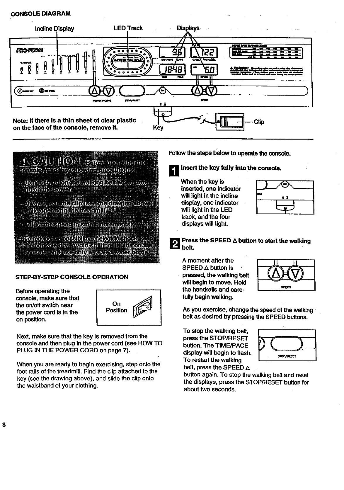
CONSOLE DIAGRAM
Incline Display LED Track Displays...
sZ l -- _-- 4• 0 _
n'-"'=-'
®'-
Note: If there Is a thin sheet of clear plastic ___._S_ Clip
on the face of the console, remove it. Key
Follow the steps below to operat e the console.
B Insert the key fully intothe console.
When the key is
inserted, one indicator
will light in the incline
display, one indicator
will light in the LED
track, and the four
displays will light.
STEP-BY-STEP CONSOLE OPERATION
Before operating the
console, make sure that
the on/off switch near
the power cord is in the
on position.
On
Position
Next, make sure that the key is removed from the
console and then plug in the power cord (see HOW TO
PLUG IN THE POWER CORD on page 7).
When you are ready to begin exercising, step onto the
foot rails of the treadmill. Find the clip attached to the
key (see the drawing above), and slide the clip onto
the waistband of your clothing.
B Press the SPEED _button to start the walking
bell
A moment after the
SPEED L_button Is
pressed, the walking belt
will begin to move. Hold
the handrails and care-
fully begin walking.
As you exercise, change the speed of the walking"
belt as desired by pressing the SPEED buttons.
To stop the walking belt,
press the STOP/RESET
button. The TIME/PACE
display will begin to flash.
To restart the walking
belt, press the SPEED ,k
button again. To stop the Walking belt and reset
the displays, press the STOP/RESET button for
about two seconds.
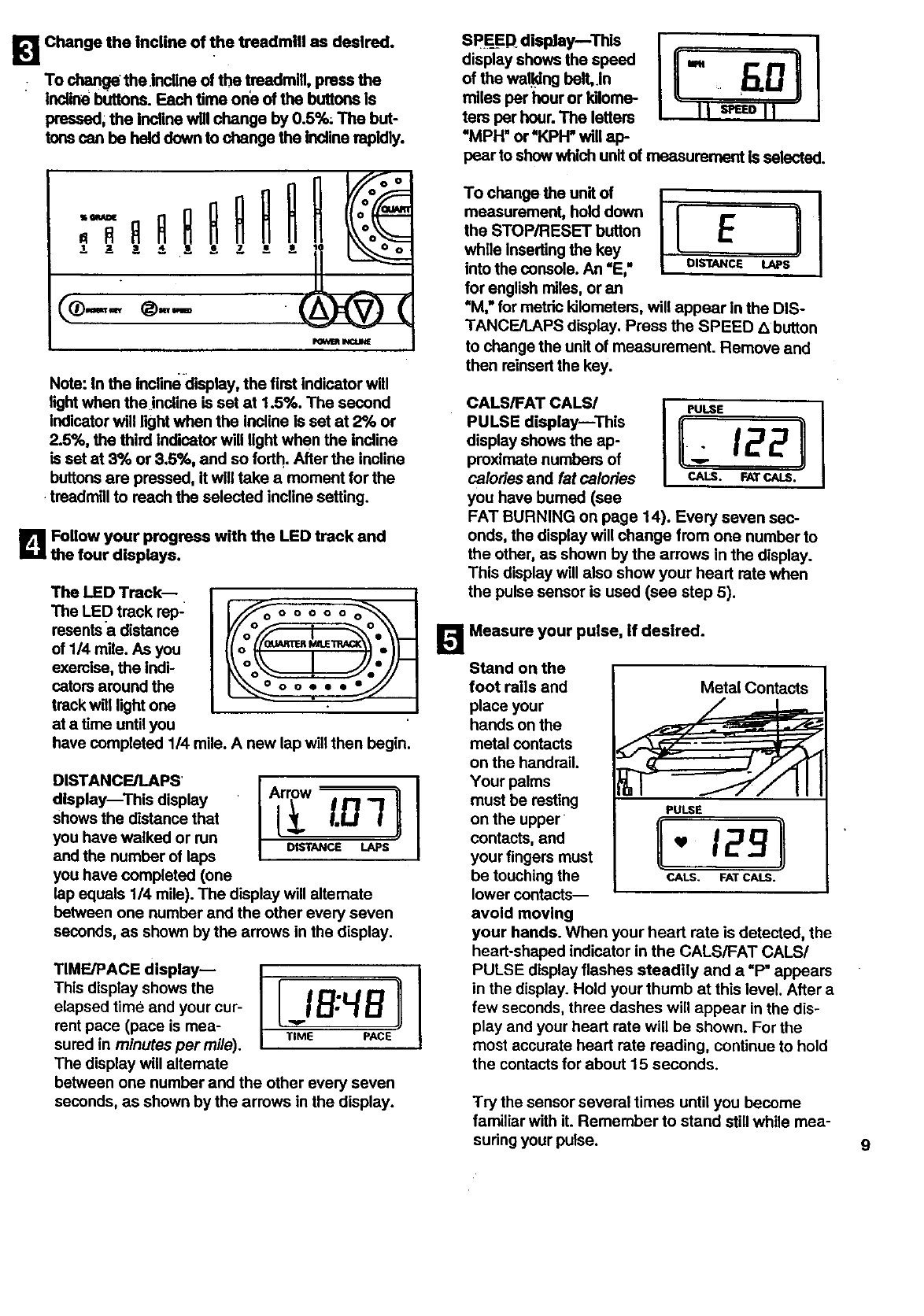
B Changethe inclineof thetreadmillas desired.
Tochangetheinclineofthetreadmill,pressthe
inclinebuttons.Eachtimeoneofthebuttonsis
pressod,theinclinewillchangeby0.5%;Thebut-
tonscanbehelddowntochangethe incline rapidly.
o
FOyeR I_OJME
Note: In the incline display, the first indicator will
fightwhen the incline is set at 1.5%. The second
indicator will light when the incline is set at 2% or
2.5%, the third indicator will light when the incline
is sot at 3% or 3.5%, and so forth. After the incline
buttonsare pressed, it wiUtake a moment for the
treadmill to reach the selected incline setting.
B Follow your progress with the LED track and
the four displays.
The LED Track--
The LED track rep-
resents a distance
of 1/4 mile. As you
exercise, the Indi-
cators around the
track witl light one
at a time until you
lO0 0 0 0 0 0 0 0
O•
Ioo...
have completed 1/4 mile. A new lap will then begin.
DiSTANCE/LAPS
display--This display
shows the distance that
you have walked or run
and the number of laps
you have completed (one
A ow11
LoT
DISTANCE LAPS
lap equals 1/4 mile). The display will alternate
between one number and the other every seven
seconds, as shown by the arrows in the display.
TiME/PACE display--
This display shows the
elapsed time and your cur-
rent pace (pace is mea-
sured in minutes per mi/e).
The display will altemate
IB:4B I
TIME PACE
between one number and the other every seven
seconds, as shown by the arrows in the display.
Sp_E=ED_dislday--This
display shows the speed
of the wal.klngbelt,.in
miles per hour or kilome-
ters per hour. The letters
*MPH" or "KPI-I=wtll ap-
pear to show which unit of measurement is selected.
To change the unit of
measurement, hold down
the STOP/RESET button
while Inserting the key
into the console. An "E,"
for english miles, or an
ILL !
'DISTANCE LAPS
"M," for metric kilometers, will appear in the DIS-
TANCE/LAPS display. Press the SPEED Z_button
to change the unit of measurement. Remove and
then reinsert the key.
CALS/FAT CALS/
PULSE displayiThis
display shows the ap-
proximate numbers of
calories and fat calories
you have burned (see
PULSE
C_ALS. rAT CALS.
FAT BURNING on page 14). Every seven sec-
onds, the display will change from one number to
the other, as shown by the arrows in the display.
This display will also show your heart rate when
the pulse sensor is used (see step 5).
_'_ Measure your pulse, if desired.
Stand on the
foot rails and Metal Contacts
place your
hands on the
metal contacts
on the handrail.
Your palms
must be resting PULSE
on the upper II ]1
contacts, snd _12.._
your fingers must
be touching the cALS. FATCALS.
lower contacts--
avoid moving
your hands. When your heart rate is detected, the
heart-shaped indicator in the CALS/FAT CALS/
PULSE display flashes steadily and a"P" appears
in the display. Hold your thumb at this level. After a
few seconds, three dashes will appear in the dis-
play and your heart rate will be shown. For the
most accurate heart rate reading, continue to hold
the contacts for about 15 seconds.
Try the sensor several times until you become
familiar with it. Remember to stand still while mea-
suring your pulse.
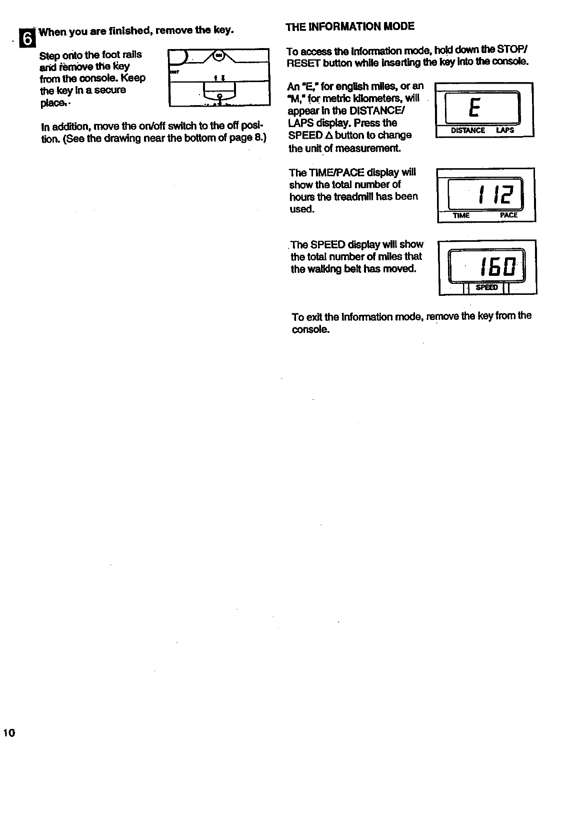
r_ When you are finished, remove the key.
Stepontothe foot rails
e.id removethe _/
fromthe console.Keep
the key In asecure
place,.
In addRion, move the on/off switch to the off posi-
tion. (See the drawing near the bottom of page 8.)
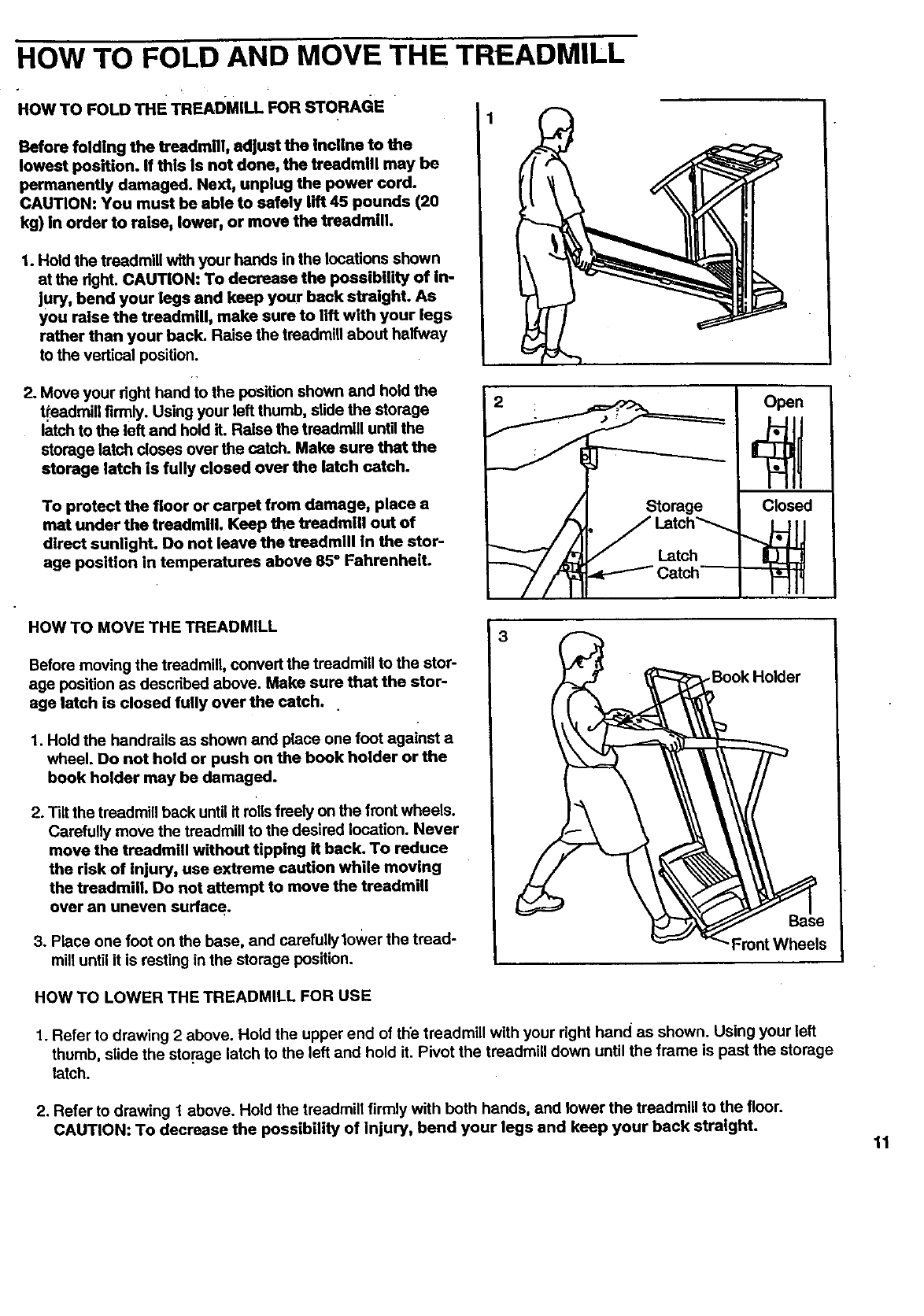
THE INFORMATION MODE
To access the Information mode, hold down the STOP/
RESET buttoo while inserUng the key into the esnsole.
"M," for metric kilometers, will .
appear in the DISTANCE/
LAPS display. Press the
SPEED _1button to change Dwr_cE LAPS
the unit of measurement.
The TIME/PACE display will
show the total number of
hours the treadmill has been
used. II Ita!
TIME pACE
.The SPEED display will show
the total number of miles that
the walking belt has moved.
To exit the Information mode, remove the keyfrom the
console.
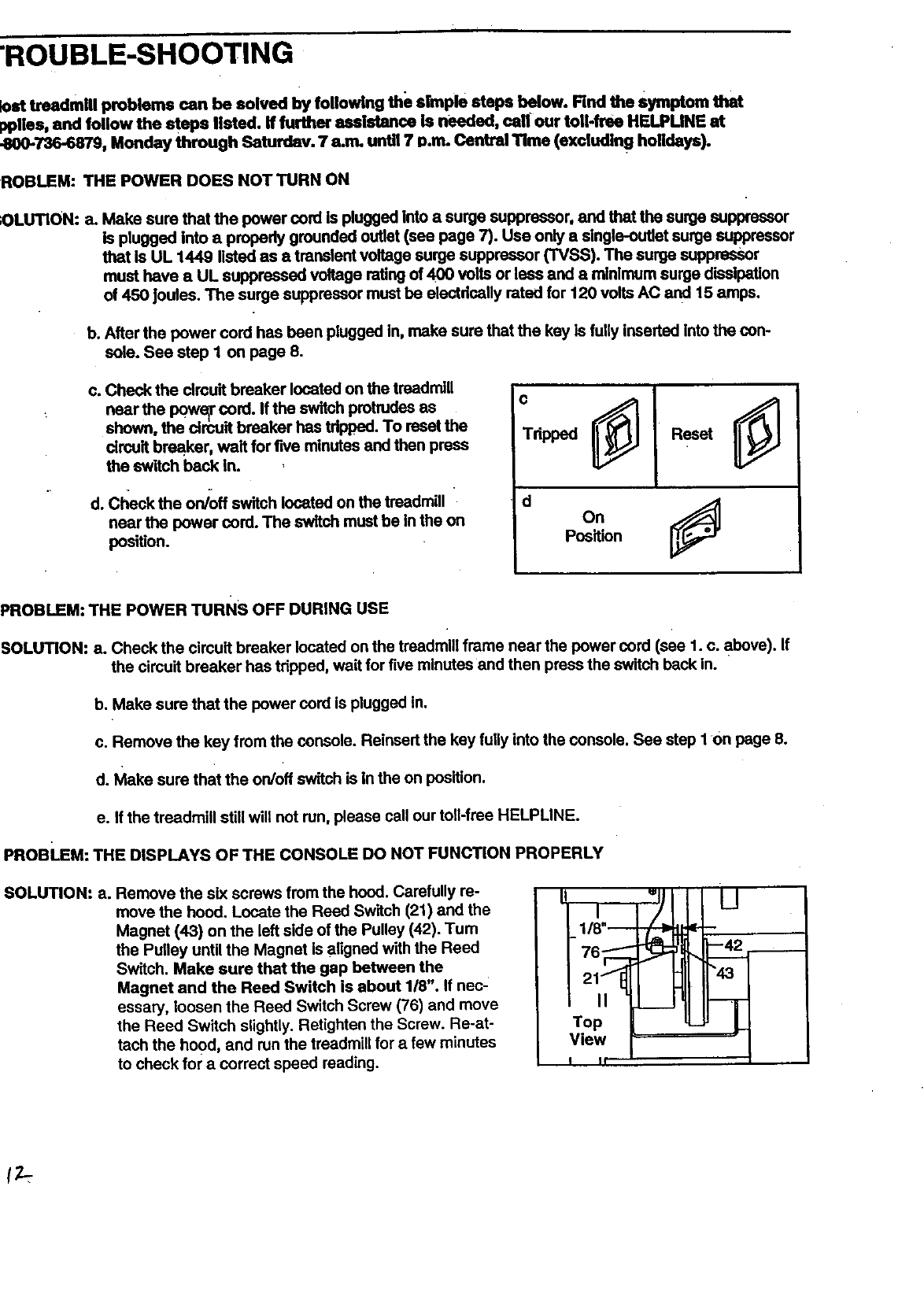
HOW TO FOLD AND MOVE THE TREADMILL
HOW TO FOLD THE TREADMILL FOR STORAGE
Before folding the treadmill, adjust the incline to the
lowest position. If this is not done, the treadmill may be
permanently damaged. Next, unplug the power cord.
CAUTION: You must be able to safely lift 45 pounds (20
kg) in order to raise, lower, or move the treadmill.
1. Hold the treadmill with your bands in the locations shown
at the dght. CAUTION: To decrease the possibility of in-
jury, bend your legs and keep your back straight. As
you raise the treadmill, make sure to lift with your legs
rather than your back. Raise the treadmill about halfway
to the vertical position.
2. Move your dght band io the position shown and hold the
tteadmiU firmly. Using your left thumb, slide the storage
latch to the left and hold it. Raise the treadmill untilthe
storage latch closes over the catch. Make sure that the
storage latch is fully closed over the latch catch.
To protect the floor or carpet from damage, place a
mat under the treadmill. Keep the treadmill out of
direct sunlight. Do not leave the treadmill in the stor-
age position in temperatures above 85 °Fahrenheit.
Open
Closed
HOW TO MOVE THE TREADMILL
Before moving the treadmill, convert the treadmill to the stor-
age position as described above. Make sure that the stor-
age latch is closed fully over the catch.
1. Hold the handrails as shown and place one foot against a
wheel. Do not hold or push on the book holder or the
book holder may be damaged.
2. Tilt the treadmill back until it rollsfreely on the front wheels.
Carefully move the treadmill to the desired location. Never
move the treadmill without tipping it back. To reduce
the risk of injury, use extreme caution while moving
the treadmill. Do not attempt to move the treadmill
over an uneven sudac e.
3. Place one foot on the base, and carefully lower the tread-
mill until it is resting in the storage position.
_Book Holder
HOW TO LOWER THE TREADMILL FOR USE
1. Refer to drawing 2 above. Hold the upper end of the treadmill with your right hand as shown. Using your left
thumb, slide the storage latch to the left and hold it. Pivot the treadmill down until the frame is past the storage
latch.
2. Refer to drawing 1above. Hold the treadmill firmly with both hands, and lower the treadmill to the floor.
CAUTION: To decrease the possibility of injury, bend your legs and keep your back straight. 11
"ROUBLE-SHOOTING
_)st treadmill problems can be solved by following the simple steps below. Rnd the Symptom that
pplies, and follow the steps listed, ff further assistance is needed, call our toll-free HELPUNE at
_B00-736-6879, Monday through Ssturdav. 7 a.m. until 7 P.m. Central Time (excluding holidays).
ROBLEM: THE POWER DOES NOT TURN ON
;OLUTION: a. Make sure that the power cord Is plugged into asurge suppressor, and that the surge suppressor
Is plugged into a propedy grounded outlet (see page 7). Use only a single-outlet surge suppressor
that is UL 1449 listed as a transient voltage surge suppressor (TVSS). The surge suppressor
must have a UL suppressed voltage rating of 400 volts or less and a mlnlmum surge dissipation
of 450 Joules. The surge suppressor must be electdcally rated for 120 volts AC and 15 amps.
b. After the power cord has been plugged In, make sure that the key ISfully inserted Into the con-
sole. See step 1 on page 8.
c. Check the circuit breaker located on the treadmill
near the p0w_ cord. If the switch protrudes as
shown, the drcuit breaker has tdpped. To reset the
circuit breaker, wait for five minutes and then press
the switch hack In.
d. Check the on/off switch located on the treadmill
near the power cord. The switch must be in the on
position.
c
Tdpped
dOn
Position
PROBLEM: THE POWER TURNS OFF DURING USE
SOLUTION: a. Check the cimuit breaker located on the treadmill frame near the power cord (see 1. c. above). If
the circuit breaker has tripped, wait for five minutes and then press the switch back in.
b. Make sure that the power cord is plugged in.
c. Remove the key from the console. Reinsert the key fully into the console. See step I On page 8.
d. Make sure that the on/off switch is In the on position.
e. If the treadmill still will not run, please call our toll-free HELPLINE.
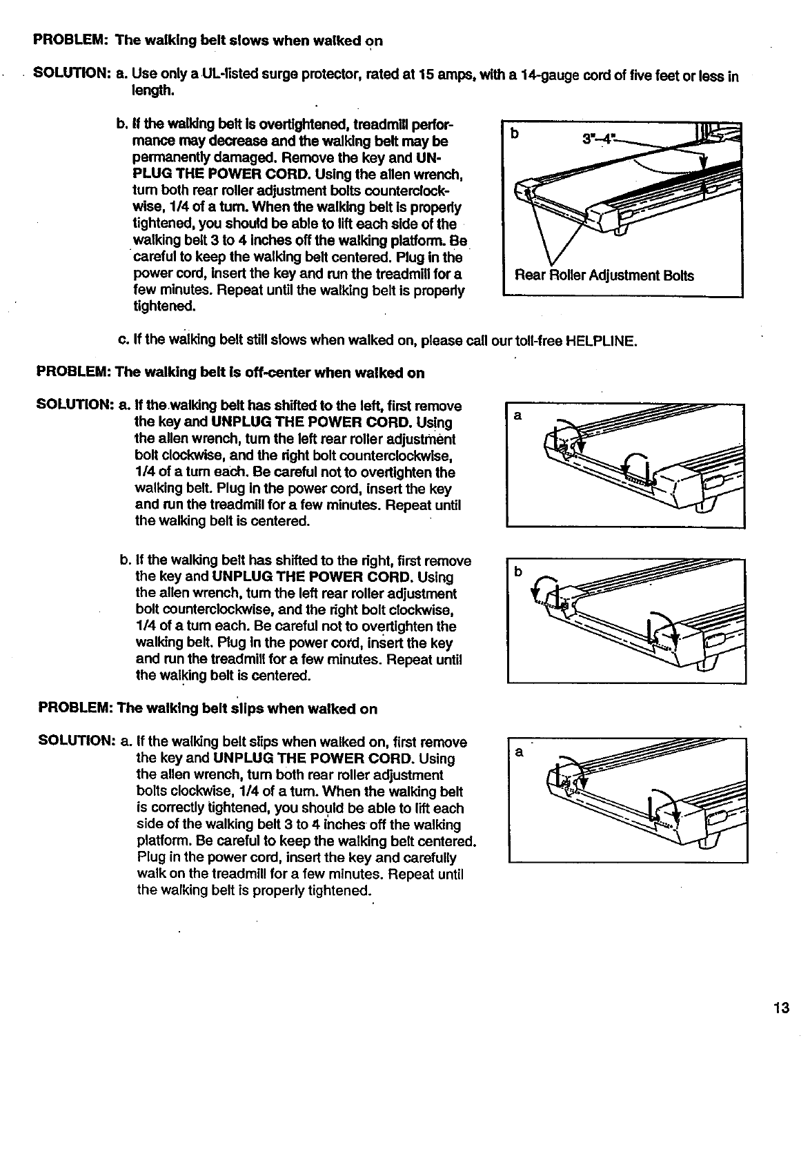
PROBUEM: THE DISPLAYS OF THE CONSOLE DO NOT FUNCTION PROPERLY
SOLUTION: a. Remove the six screws from the hood. Carefully re-
move the hood. Locate the Reed Switch (21) and the
Magnet (43) on the left side of the Pulley (42). Turn
the Pulley until the Magnet is aligned with the Reed
Switch. Make sure that the gap between the
Magnet and the Reed Switch is about 118". If nec-
essary, loosen the Reed Switch Screw (76) and move
the Reed Switch slightly. Retighten the Screw. Re-at-
tach the hood, and run the treadmill for a few minutes
to check for a correct speed reading.
" ,° 111u
I
t/8
I If '
PROBLEM: The walking belt slows when walked on
• SOLUTION: a. Use only a UL-Iisted surge protector, rated at 15 amps, with a 14-gauge cord of five feet or less in
length.
b. If the walking belt is overtlghtened, treadmill perfor-
mance may decrease and the walking belt may be
permanently damaged. Remove the key and UN-
PLUG THE POWER CORD. Using the allen wrench,
tum both rear roller adjustment bolts counterclock-
wise, 1/4 of a turn. When the walking belt is propedy
tightened, you should be able to lift each side of the
walking belt 3 to 4 inches off the walking platform. Be
careful to keep the walking belt centered. Plug in the
power cord, insert the key and run the treadmill for a
few minutes. Repeat until the walking belt is propedy
tightened.
Rear Roller Adjustment Bolts
c. If the walking belt still slows when walked on, please call our toll-free HELPLINE.
PROBLEM: The walking belt is off-center when walked on
SOLUTION: a. If the walking belt has shifted to the left, first remove
the key and UNPLUG THE POWER CORD. Using
the allen wrench, tum the left rear roller adjustment
bolt clockwise, and the dght bolt counterclockwise,
1/4 of atum each. Be careful not to overUghten the
walking belt. Plug In the power cord, insert the key
and run the treadmill for afew minutes. Repeat until
the walking belt is centered.
a
b. If the walking belt has shifted to the dght, first remove
the key and UNPLUG THE POWER CORD. Using
the allen wrench, tum the left rear roller adjustment
bolt counterclockwise, and the dght bolt clockwise,
1/4 of a turn each. Be careful not to overtlghten the
walking belt. Plug In the power cord, insert the key
and run the treadmill for a few minutes. Repeat until
the walking belt is centered.
PROBLEM: The walking belt Slips when walked on
SOLUTION: a. If the walking belt slips when walked on, first remove
the key and UNPLUG THE POWER CORD. Using
the allen wrench, tum both rear roller adjustment
bolts clockwise, 1/4 of a turn. When the walking belt
is correctly tightened, you should be able to lift each
side of the walking belt 3 to 4inches off the walking
platform. Be careful to keep the walking belt centered.
Plug in the power cord, insert the key and carefully
walk on the treadmill for a few minutes. Repeat until
the walking belt is properly tightened.
b
a"
13
. CONDITIONING GUIDELINES
The following guidelines will help you to plan your ex-
ercise program. Remember--these are general guide-
lines only. For more detailed exercise information, ob-
tain a reputable book or consult your physician.
EXERCISE INTENSITY
Whether your goal is to bum fat or to strengthen your
cardiovascular system, the key to achieving the
desired results is to exercise with the proper intensity.
The proper intensity level can be found by using your
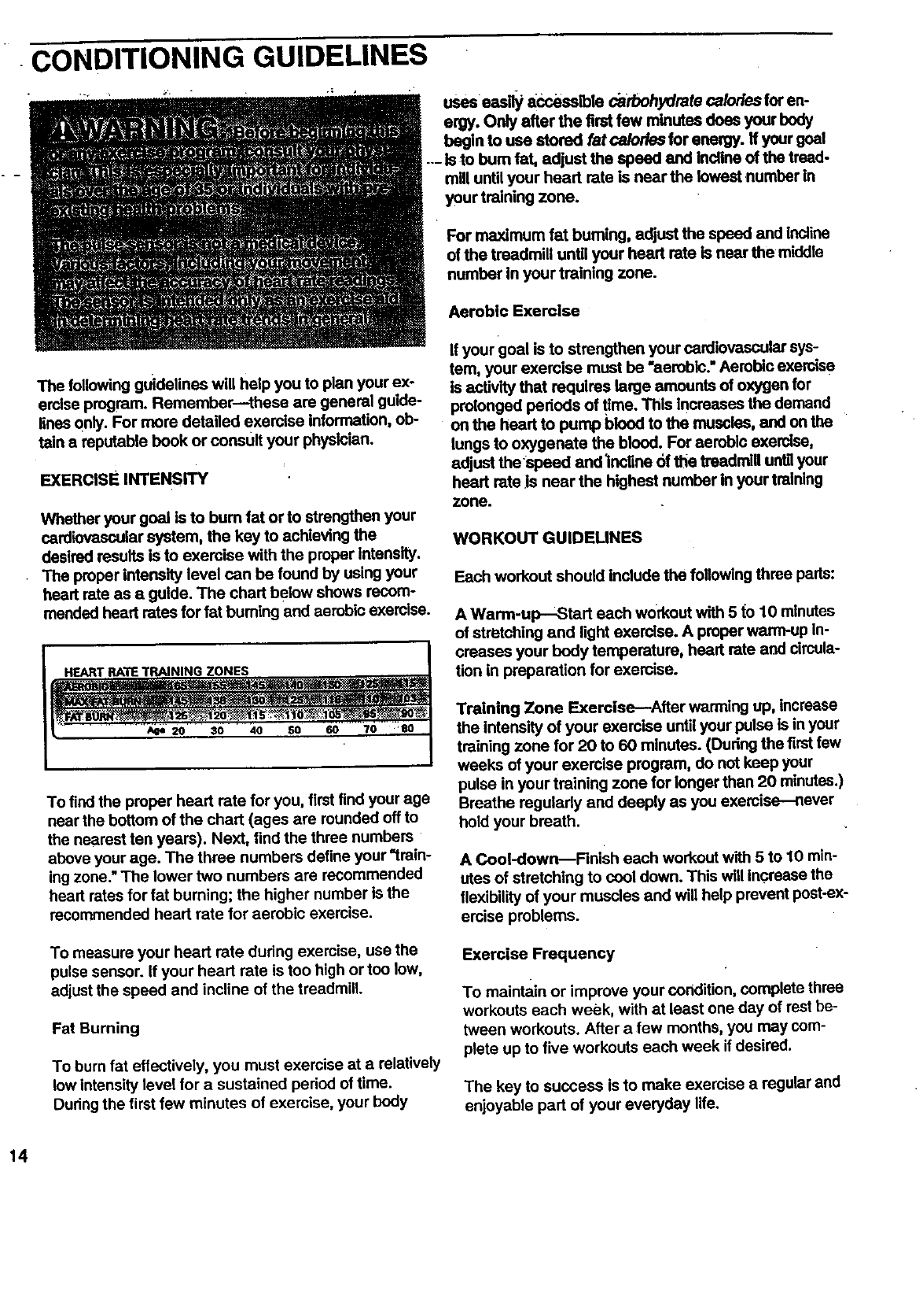
heart rate as aguide. The chart below shows recom-
mended heart rates for fat buming and aerobic exercise.
HEART RATE TRAINING ZONES
20 30 40 50 70 BO
To find the proper heart rate for you, first find your age
near the bottom of the chart (ages are rounded off to
the nearest ten years). Next, find the three numbers
above your age. The three numbers define your "train-
ing zone." The lower two numbers are recommended
heart rates for fat burning; the higher number is the
recommended heart rate for aerobic exercise.
To measure your heart rate during exemise, use the
pulse sensor, ff your heart rate is too high ortoo low,
adjust the speed and incline of the treadmill.
Fat Burning
To burn fat effectively, you must exercise at a relatively
low intensity level for asustained period of time.
During the first few minutes of exercise, your body
uses eesily _,ccesslble carbohydrate ca/ories for en-
ergy. Only after the first few minutes does your body
begin to use stored fat ca/or/es for energy. If your goal
--- is to bum fat, adjust the speed and incline of the tread-
mill until your head rate is near the lowest number in
your training zone.
For maximum fat burning, adjust the speed and incline
of the treadmill until your heart rate is nesr the middle
number In your training zone.
Aerobic Exercise
If your goal is to strengthen your cardiovascular sys-
tem, your exercise must he "aerobic." Aerobio exercise
is activity that requires large amounts of oxygen for
prolonged pededs of time. This Increases the demand
on the heart to pump blood to the muscles, and on the
lungs to oxygenate the blood. For aerobic exercise,
adjust the speed and lnsrlne of the treadmill untilyour
heart rate Js near the highest number in your training
zone.
WORKOUT GUIDELINES
Each workout should include the following three pads:
A Warm-up--Start each workout with 5 to 10 minutes
of stretching and light exercise. A proper warm-up In-
creases your body temperature, heart rate and circula-
tion in preparation for exemise.
Training Zone Exercise--After warming up, increase
the intensity of your exercise until your pulse is in your
training zone for 20 to 60 minutes. (Dudng the first few
weeks of your exercise program, do not keep your
pulse in your training zone for longer than 20 minutes.)
Breathe regularly and deeply as you exercise-never
hold your breath.
A Cool-down--Finish each workout with 5 to 10 min-
utes of stretching to cool down. This will increase the
flexibility of your muscles and will help prevent post-ex-
ercise problems.
Exercise Frequency
To maintain or improve your condition, complete three
workouts each week, with at least one day of rest be-
tween workouts. After afew months, you may com-
plete up to five workouts each week if desired.
The key to success isto make exercise a regular and
enjoyable part of your everyday life.
i
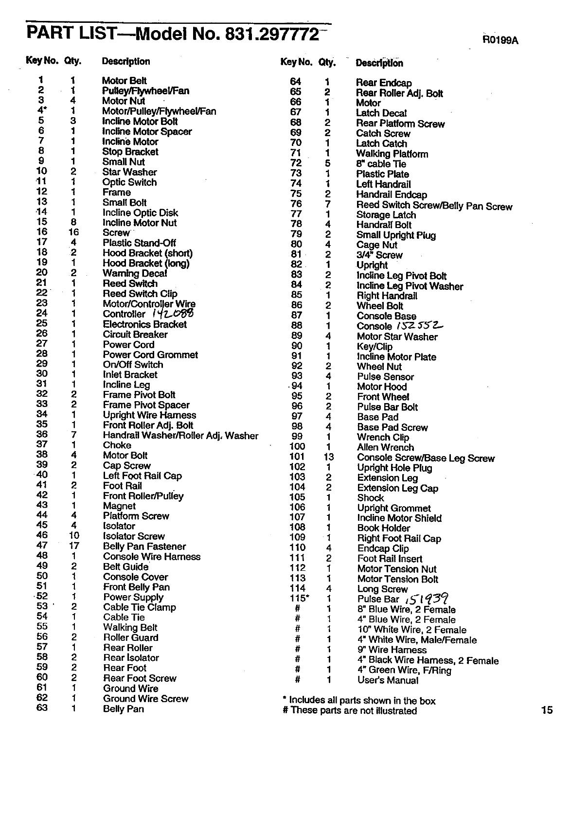
PART LIST---Model No. 831.297772- R01 A
KeyNo. Qty. Oescdptlon KeyNo. Qty.
1 1 Motor Belt 64 1
2 1 Pulley/Flywheel/Fan 65 2
3 4 Motor Nut 66 1
4* 1 Motor/Pulley/Flywheel/Fan 67 1
5 3 Incline Motor Belt 68 2
6 1 Incline Motor Spacer 69 2
7 1 Inclini3Motor 70 1
8 1 Stop Bracket 71 1
9 1 Small Nut 72 5
10 2 Star Washer 73 1
.11 1 Optic Switch 74 1
12 1 Frame 75 2
13 1 Small Bolt 76 7
.14 1 Incline Optic Disk 77 1
15 8 Incline Motor Nut 78 4
16 16 Screw 79 2
17 4 Plastic Stand-Off 8O 4
18 2 Hood Bracket (short) 81 2
19 1 Hood Bracket (long) 82. 1
20 2 Wam|ng Decal 83 2
21 1 Reed Switch 84 2
22 1 Reed Switch Clip 85 1
23 1 Motor/Controller Wire 86 2
24 1 Controller r''_Z_ 87 1
25 1 Electronics Bracket 88 1
26 1 Circuit Breaker 89 4
27 1 Power Cord 90 1
28 1 Power Cord Grommet 91 1
29 1 On/Off Switch 92 2
30 1 Inlet Bracket 93 4
31 1 Incline Leg •94 1
32 2 Frame Pivot Bolt 95 2
33 2 Frame Pivot Spacer 96 2
34 1 Upright Wire Harness 97 4
35 1 Front RoUerAdj, Belt 98 4
36 7 Handrail Washer/Roller Adj, Washer 99 1
37 1 Choke 100 1
38 4 Motor Belt 101 13
39 2 Cap Screw 102 1
•40 1 Left Foot Rail Cap 103 2
41 2 Foot Rail 104 2
42 1 Front Roller/Pulley 105 1
43 1 Magnet 106 1
44 4 Platform Screw 107 1
45 4 Isolator 108 1
46 10 Isolator Screw 109 1
47 17 Belly Pan Fastener 110 4
48 1 Console Wire Harness 111 2
49 2 Belt Guide' 112 1
50 1 Console Cover 113 1
51 1 Front Belly Pan 114 4
•52 1 Power Supply 115" 1
53 ' 2 Cable Tie Clamp #1
54 1 Cable Tie #1
55 1 Walking Belt # 1
56 2 Roller Guard # 1
57 1 Rear Roller # 1
58 2 Rear Isolator # 1
59 2 Rear Foot # 1
60 2 Rear Foot Screw # 1
61 1 Ground Wire
62 1 Ground Wire Screw
63 1 Belly Pan
"DesCd_tlon
Reer
Rear Roller Adj. Bolt
Motor
Latch Decal
Rear Platform Screw
Catch Screw
Latch Catch
Walking Platform
8" cable 3qe
Plastic Plate
Left Handrail
Handrail Endcsp
Reed Switch Screw/Belly Pan Screw
Storage Latch
Handrai! Bolt
Small Updght Plug
Cage Nut
3/4,"Screw
Upright
Incline Leg Pivot Bolt
Incline Leg Pivot Washer
Right Handrail
Wheel Bolt
Console Base
Console /57- 3"5"Z.-
Motor Star Washer
Key/Clip
Incline Motor Plate
Wheel Nut
Pulse Sensor
Motor Hood
Front Wheel
Pulse Bar Bolt
Base Pad
Base Pad Screw
Wrench Clip
Allen Wrench
Console Screw/Base Leg Screw
Upright Hole Plug
Extension Leg
Extension Leg Cap
Shock
Upright Grommet
Incline Motor Shield
Book Holder
Right Foot Rail Cap
Endcap Clip
Foot Rail Insert
Motor Tension Nut
Motor Tension Bolt
Long Screw
Pulse Bar ,,_['_
8" Blue Wire, 2Female
4" Blue Wire, 2 Female
10" White Wire, 2 Female
4" White Wire, Male/Female
9" Wire Hamees
4" Black Wire Harness, 2 Female
4" Green Wire, F/Ring
User's Manual
*Includes all parts shown in the box
#These parts are not illustrated 15
Model No,..8,3.,I,_ZZ2.._ •
QUESTIONS?
If you find that:
• you need help aseembling or
operating the PROFORM 595LE
treadmill
•e part is missing
•or you need to schedule repair
service
call our toll-free HELPUNE
1-800-736-6879
Monday-Saturday, 7 am-7 pm
Central Time (excluding holidays)
REPLACEMENT
PARTS
If parts become worn and need
to be replaced, call the following
toll-free number
1-800-FON-PART
(1-800-366-7278)
The model number and eedal number of your PROFORM" 595LE
treadmill are listed on a decal attached to the frame. See the front
cover of this manual to find the location of the decal.
All mplaoement pads are available for immediate purchase or
sPecial order when you visit your nearest SEARS Service Center.
To request service or to order parts by telephone, call the toll-free
numbers listed at the left.
When requesting he p or service, or ordedng parts, please be
prepared to provide the following information:
• The NAME OF THE PRODUCT (PROFORM •595LE treadmill)
•The MODEL NUMBER OF THE PRODUCT (831.297772)
•The KEY NUMBER AND DESCRIPTION OF THE PART (see the
EXPLODED DRAWING and PART LIST included in this manual)
FULL 90 DAY WARRANTY
For 90 days from the date of purchase, if failure occurs due to defect in matedal or workmanship in this
SEARS TREADMILL EXERCISER, contact the nearest SEARS Service Center throughout the United
States and SEARS will repair or replace the TREADMILL EXERCISER, free of charge.
This warranty does not apply when the TREADMILL EXERCISER is used commercially or for rental pur-
poses.
This warranty gives you specific legal dghts, and you may also have other rights which vary from state
to state.
SEARS, ROEBUCK AND CO., DEPT. 817WA, HOFFMAN ESTATES, IL 60179
Pad No. 152638 J00124-C R0199A Pdnted in USA ©1999 Sears, Roebuck and Co.
