Proform 831299216 User Manual CROSSWALK XL Manuals And Guides L0010528
PROFORM Treadmill Manual L0010528 PROFORM Treadmill Owner's Manual, PROFORM Treadmill installation guides
User Manual: Proform 831299216 831299216 PROFORM CROSSWALK XL - Manuals and Guides View the owners manual for your PROFORM CROSSWALK XL #831299216. Home:Fitness Equipment Parts:Proform Parts:Proform CROSSWALK XL Manual
Open the PDF directly: View PDF ![]() .
.
Page Count: 18
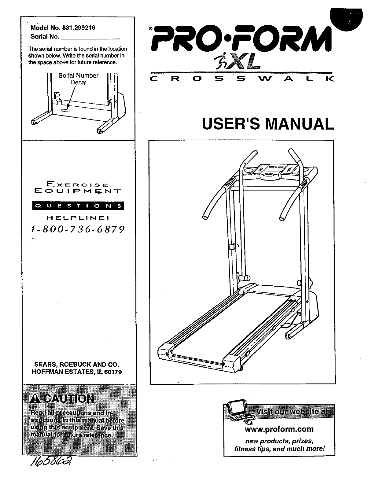
" Model No. 831.299216
Serial No.
The serialnumberisfound inthe location
shownbelow.Write theserialnumberin
the spaceaboveforfuture reference.
Serial Number
Decal
F-x E R C i ._ F_
F- C_, U I p M I_ NT
HELPLINE!
1-800-736-6879
SEARS, ROEBUCK AND CO.
HOFFMAN ESTATES, IL 60179
PRO.FORM m
C R 0 S S W A L K
USER'S MANUAL
www.proform.com
new products, prizes,
fitness tips, and much morel
TABLE OF CONTENTS
IMPORTANT PRECAUTIONS ................................................................. 2
BEFORE YOU BEGIN ....................................................................... 4
ASSEMBLY ............................................................................... 5
OPERATION AND ADJUSTMENT ............................................................. 7
HOW TO FOLD AND MOVE THE TREADMILL .................................................. 10
TROUBLE-SHOOTING ..................................................................... 12
CONDITIONING GUIDELINES ............................................................... 14
ORDERING REPLACEMENT PARTS .................................................. Back Cover
FULL 90 DAY WARRANTY ........................................................... Back Cover
Note: An EXPLODED DRAWING and a PART LIST are attached if] the center of this manual. Save the
EXPLODED DRAWING and PART LIST for hJture reference.
IMPORTANT PRECAUTIONS
i : tistherespohsbtltyOftheowdert0enSUre 9. Weat
garage or cover o, or near water.
5. Do not operate the treadmill where aerosol 11. Use only a singl_-outlet surge suppressor that
products are used or where oxygen s being is UL 1449 listed aS a transieh_ _01tage s_Jrge
administered.- Suppressor (TVSS). lhe surge suppressor: _
must have a UL S_uppressed voltage rating of
6. Keep children under the a_e of 12 and pets 400 volts or less and a minimum surge dissi-
away from the treadmill at all times, pation of 450 joules. The surge suppressor
must be electrically rated for 120 volts AC and
7, The treadmill should be used only by persons 15 amps. To purchase a surge suppressor, see
weighing 250 pounds or less. your local PREFORM dealer or call 1-800-366-
7278 and order part number 14657.
8. Never allow more than one person on the
treadmill at a time. 12. Keep the power cord and the surge suppres-
sor away from heated surfaces,
13. Never move the walking belt while the power to raise, lower; of move the treadmill.
is turned off- Do not operate t!_e treadm II if
the p0wer cord or plUg is damaged, or if the 18.
treacimili is not working pr0perly. (see BE- sure that the storage latch is full
FORE YOU •BEGIN on page 4 if the treadmill
is not work ng proper y ) 19. Inspect and tighten all pz
;:. ...... ; every three rnont'hs;
14. Never start the treadmill whi eyou are
standing on the walking belt. Always hold 20. Never drop or insert any Object into any
the handrails or upper body arms while
using the treadmill.
15.The treadmill is capable of high speeds.
Adjust the speed in small increments to
avoid sudden jumps in speed.
16: Never leave the treadmill unattended while
it is running. Always remove the key and un-
plug the po_ver €oi'd when the treadmill is
not in:Use_
open!ng. :: : :::
21. DAN GER. Always unplug the power ..:
cord immed ately after use, before cleaning : i ;.
the treadmill, and before performingthe : i.:
maintenance and adjdstment pr0cedures .: :•
n th s manual. Never rem0Ve•the
hood unless instructed to doso by...: .:
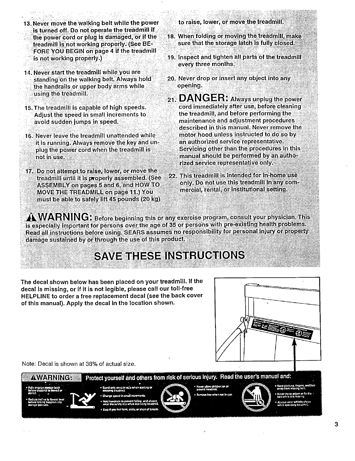
The decal shown below has been placed on your treadmill. If the
decal is missing, or if it is not legible, please call our toll-free
HELPLINE to order a free replacement decal (see the back cover
of this manual). Apply the decal in the location shown.
Note: Decal is shown at 38% of actual size.
3
BEFORE YOU BEGIN
Thank you for selecting the new PROFORM e CROSS-
WALK XL treadmill. The CROSSWALK XL treadmill
combines advanced technology with innovative design
to let you enjoy an excellent form of cardiovascular ex-
ercise in the convenience and privacy of your home.
And when you're not exercising, the unique CROSS-
WALK XL can be folded up, requiring less than half the
floor space of other treadmills.
For your benefit, read this manual carefully before
using the treadmill, ff you have additional questions,
please call our toll-free HELPLINE at 1-800-736-6879, -
Monday through Saturday, 7 a.mountil 7 p.m. Central
Time (excluding holidays). To help us assist you,
please note the product model number and serial num-
ber before calling. The model number of the treadmill
is 831.299216. The serial number can be found on a
decal attached to the treadmill (see the front cover of
this manual for the location).
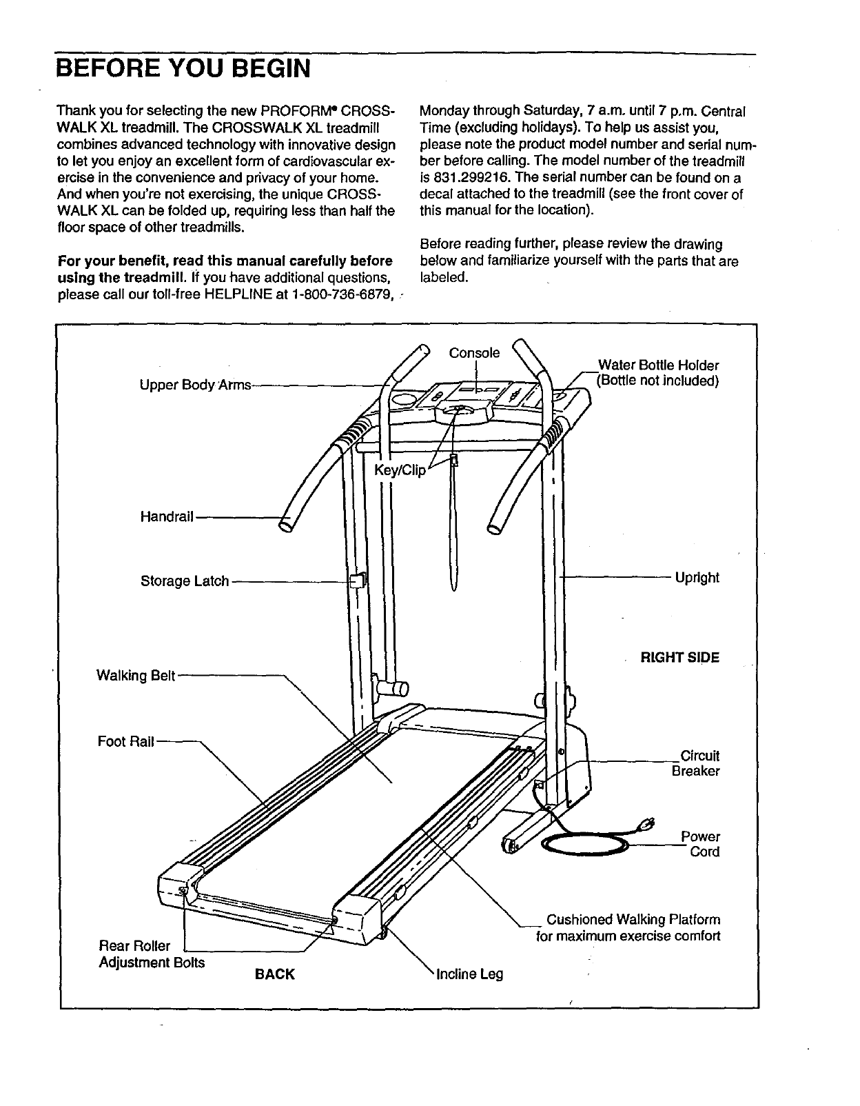
Before reading further, please review the drawing
below and familiarize yourself with the parts that are
labeled.
Upper Body i_,rms.
Console Water Bottle Holder
Handrail
Storage Latch
Walking Belt \\
,/Clip/f
Upright
RIGHT SIDE
Circuit
Breaker
Power
Cod
Cushioned Walking Platform
for maximum exercise comfort
Rear Roller
Adjustment Bolts BACK Incline Leg
ASSEMBLY
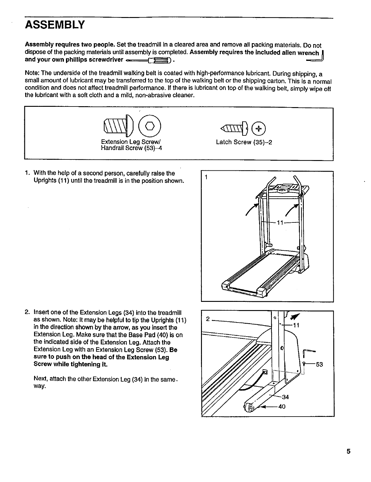
Assembly requires two people. Set the treadmill in a cleared area and remove all packing materials, Do not
dispose of the packing materials untilassembly is completed. Assembly requires the included allen wrench _
and your own phillips screwdriver _.
Note: The underside of the treadmill walking belt is coated with high-performance lubricant. During shipping, a
small amount of lubricant may be transferred to the top of the walking belt or the shipping carton. This is a normal
condition and does not affect treadmill performance. If there is lubricant on top of the walking belt, simply wipe off
the lubricant with a soft cloth and a mild, non-abrasive cleaner.
Extension Leg Screw/
Handrail Screw (53)-4 Latch Screw (35)-2
1. With the help of asecond person, carefully raise the
Uprights (11) until the treadmill is in the position shown.
2. Insert one of the Extension Legs (34) into the treadmill
as shown. Note: It may be helpful to tip the Uprights (11)
in the direction shown by the arrow, as you insert the
Extension Leg. Make sure that the Base Pad (40) is on
the indicated side of the Extension Leg. Attach the
Extension Leg with an Extension Leg Screw (53). Be
sure to push on the head of the Extension Leg
Screw while tightening it.
Next, attach the other Extension Leg (34) in the same.
way.
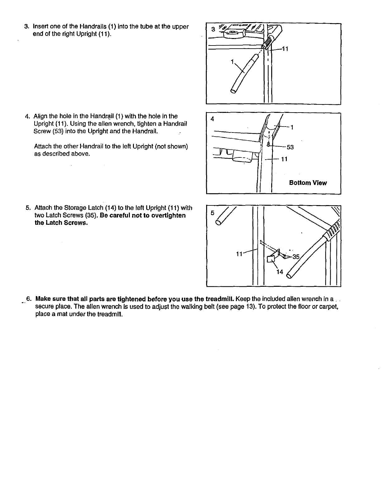
3. Insert one of the Handrails (1) into the tube at the upper
end of the dght Upright (11).
4. Align the hole in the Hand_il (1) with the hole in the
Upright (11). Using the allen wrench, tighten a Handrail
Screw (53) into the Upright and the Handrail.
Attach the other Handrail to the left Upright (not shown)
as described above.
Bottom View
5. Attach the Storage Latch (14) to the left Upright (11) with
two Latch Screws (35). Be careful not to overUghten
the Latch Screws.
11t
14
6. Make sure that all parts are tightened before you use the treadmill. Keep the included allen wrench in a _
secure place. The allen wrench is used to adjust the walking belt (see page 13). To protect the floor or carpet,
place a mat under the treadmill.
OPERATION AND ADJUSTMENT
THE PERFORMANT LUBE TM WALKING BELT
Your treadmill features a walking belt coated with
PERFORMANT LUBE TM, a high-performance lubricant.
IMPORTANT: Never apply silicone spray or other
substances to the walking belt or the walking plat-
form. Such substances will deteriorate the walking
belt and cause excessive wear.
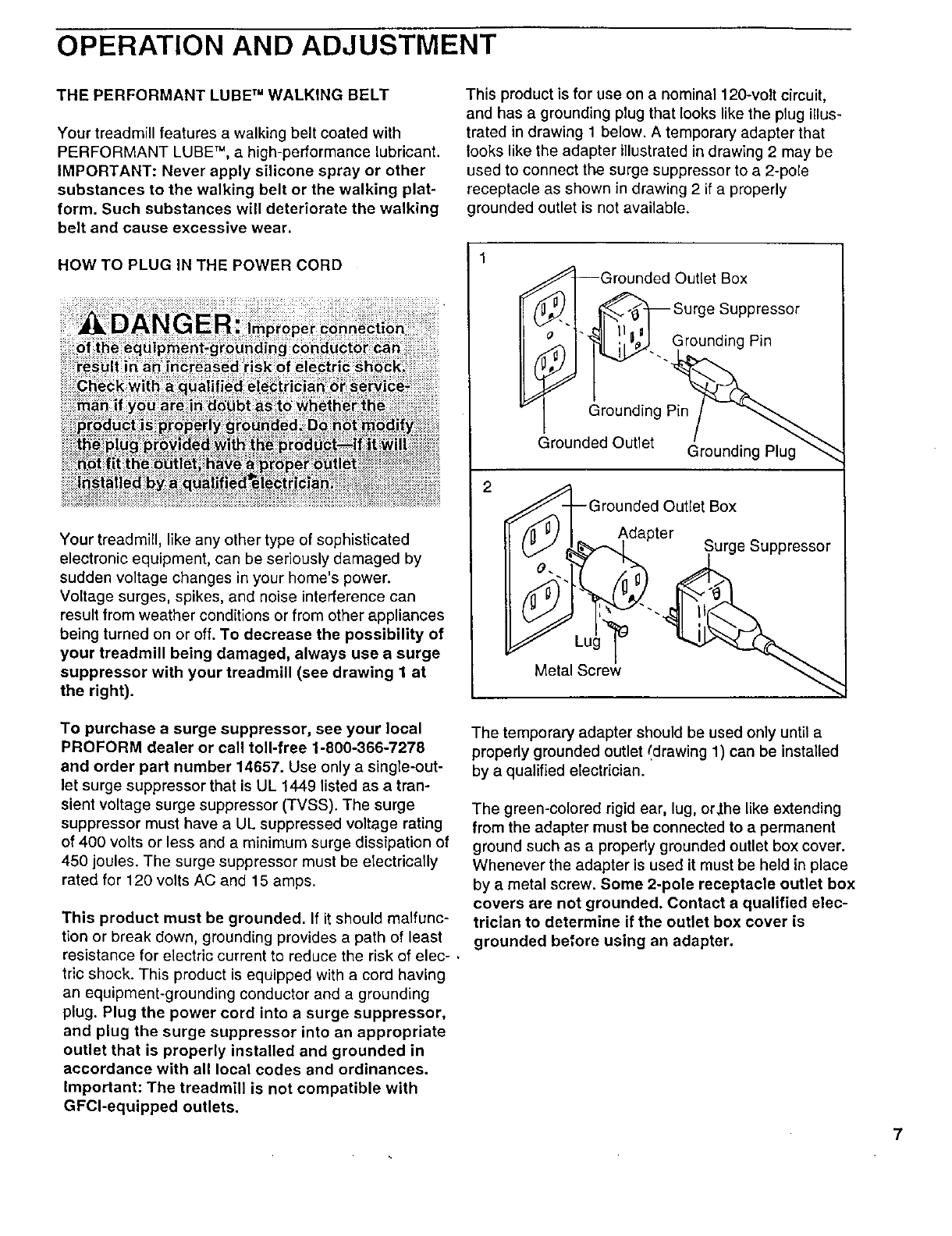
HOW TO PLUG IN THE POWER CORD
Your treadmill, like any other type of sophisticated
electronic equipment, can be seriously damaged by
sudden voltage changes in your home's power.
Voltage surges, spikes, and noise interference can
result from weather conditions or from other appliances
being turned on or off. To decrease the possibility of
your treadmill being damaged, always use a surge
suppressor with your treadmill (see drawing 1 at
the right).
To purchase a surge suppressor, see your local
PROFORM dealer or call toll-free 1-800-366-7278
and order part number 14657. Use only a single-out-
let surge suppressor that is UL 1449 listed as a tran-
sient voltage surge suppressor (TVSS). The surge
suppressor must have a UL suppressed voltage rating
of 400 volts or less and a minimum surge dissipation of
450 joules. The surge suppressor must be etectrically
rated for 120 volts AC and 15 amps.
This product must be grounded. If it should malfunc-
tion or break down, grounding provides a path of least
resistance for electric current to reduce the risk of elec-
tric shock. This product is equipped with a cord having
an equipment-grounding conductor and a grounding
plug. Plug the power cord into a surge suppressor,
and plug the surge suppressor into an appropriate
outlet that is properly installed and grounded in
accordance with all local codes and ordinances.
Important: The treadmill is not compatible with
GFCl-equipped outlets.
This product is for use on a nominal 120-volt circuit,
and has a grounding plug that looks like the plug illus-
trated in drawing 1 below. A temporary adapter that
looks like the adapter illustrated in drawing 2may be
used to connect the surge suppressor to a 2-pole
receptacle as shown in drawing 2 if a properly
grounded outlet is not available.
Outlet Box
Suppressor
Grounding Pin
2
Grounding Pin
Grounded Outlet Grounding Plug
€_--Grounded Outlet Box
Adapter
(_Y L6%_-,,._ da Surge Suppressor
Metal Screw
The temporary adapter should be used only until a
properly grounded outlet !drawing 1) can be installed
by a qualified electrician.
The green-colored rigid ear, lug, or.the like extending
from the adapter must be connected to a permanent
ground such as a properly grounded outlet box cover.
Whenever the adapter is used it must be held in place
by a metal screw. Some 2-pole receptacle outlet box
covers are not grounded. Contact aqualified elec-
trician to determine if the outlet box cover is
grounded before using an adapter.
7
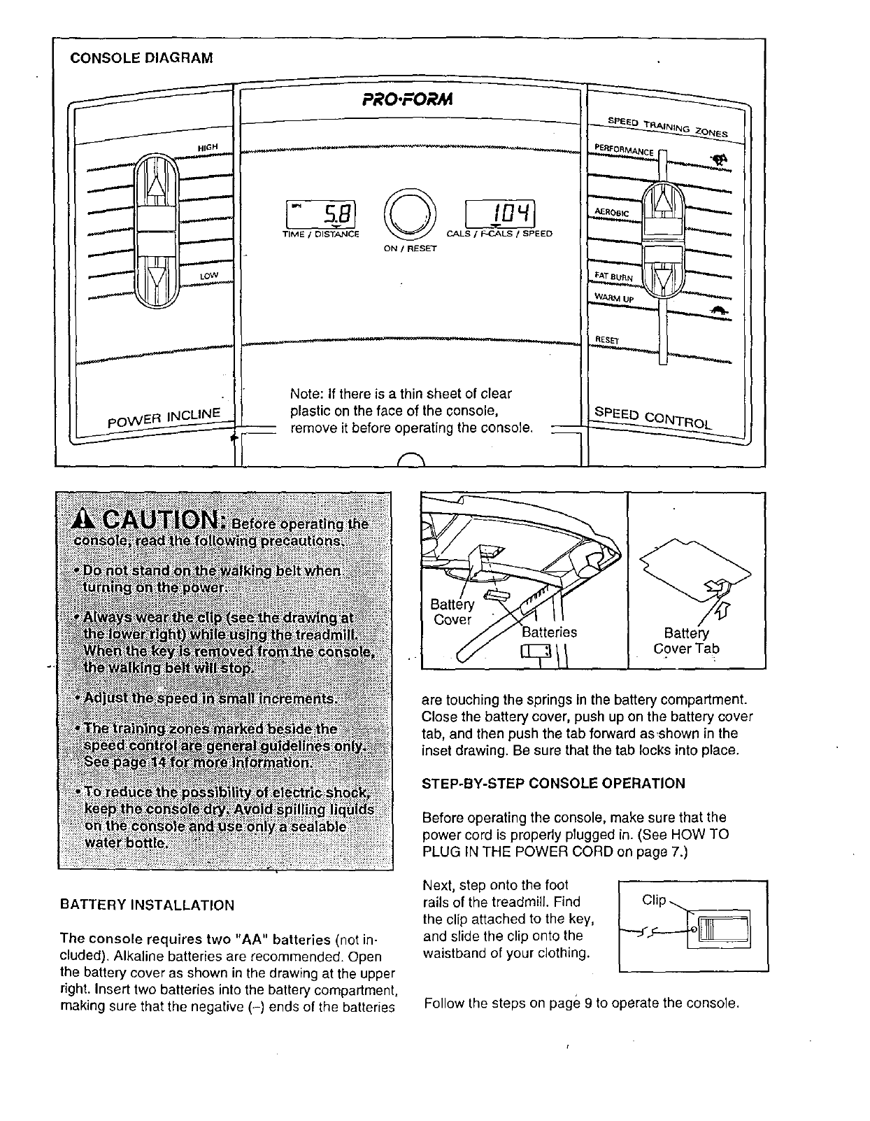
CONSOLE DIAGRAM
/HIGH
I "--"---
LOW
PRO.FORM
TIME /DISTANCE CALS /_C.ALS /SPEED
ON /RESET
BATTERY INSTALLATION
The console requires two "AA" batteries (not in-
cluded). Alkaline batteries are recommended. Open
the battery cover as shown in the drawing at the upper
right. Insert two batteries into the battery compartment,
making sure that the negative (-) ends of the batteries
are touching the springs in the battery compartment.
Close the battery cover, push up on the battery cover
tab, and then push the tab forward as ,shown in the
inset drawing. Be sure that the tab locks into place.
STEP-BY-STEP CONSOLE OPERATION
Before operating the console, make sure that the
power cord is properly plugged in. (See HOW TO
PLUG IN THE POWER CORD on page 7.)
Next, step onto the foot
rails of the treadmill. Find
the clip attached to the key,
and slide the clip onto the
waistband of your clothing.
Follow the steps on page 9 to operate the console.
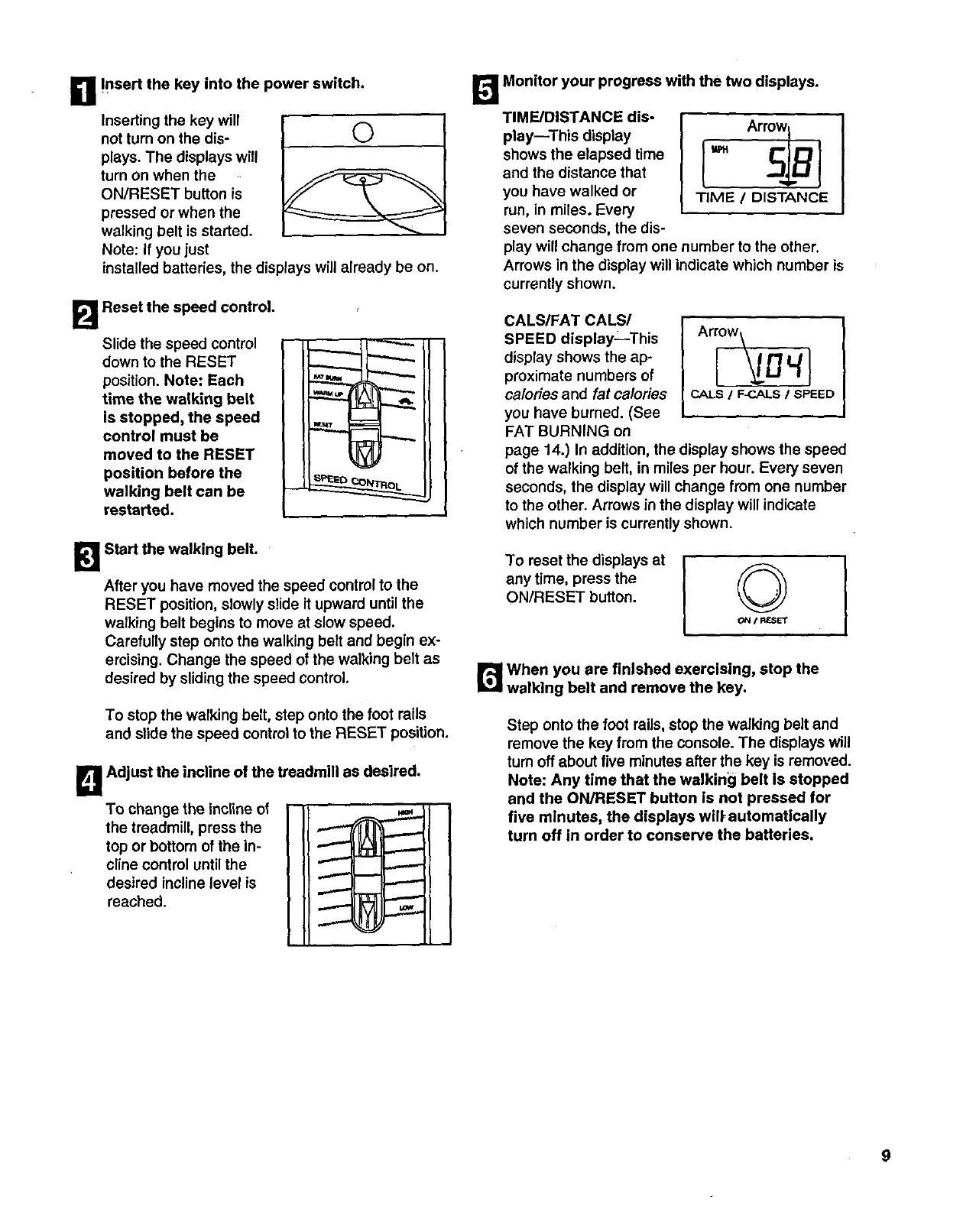
B!nsert the key into the power switch.
Inserting the key will
not turn on the dis- (_
plays. The displays will
turn on when the
ON/RESET button is
pressed or when the
walking belt is started.
Note: If you just
installed batteries, the displays will already be on.
B Reset the speed control.
Slide the speed control
down to the RESET
position. Note: Each
time the walking belt
is stopped, the speed
control must be
moved to the RESET
position before the
walking belt can be
restarted.
1_1 Start the walking belt.
After you have moved the speed control to the
RESET position, slowly slide it upward until the
walking belt begins to move at slow speed.
Carefully step onto the walking belt and begin ex-
ercising. Change the speed of the walking belt as
desired by sliding the speed control,
To stop the walking belt, step onto the foot roils
and slide the speed control to the RESET position.
To change the incline of
the treadmill, press the
top or bottom of the in-
cline control until the
desired incline level is
reached.
B Adjust the incline of the treadmill as desired.
B Monitor your progress with the two displays.
TIME/DISTANCE dis-
play--This display
shows the elapsed time
and the distance that
you have walked or
run, in miles. Every
seven seconds, the dis-
Arrow
°sl l
TIME /DISTANCE
play will change from one number to the other.
Arrows in the display will indicate which number is
currently shown.
CALS/FAT CALS/
SPEED display--This
display shows the ap-
proximate numbers of
calories and fat calories
you have burned. (See
FAT BURNING on
Arrow\
CALS /F_..ALS /SPEED
page 14.) In addition, the display shows the speed
of the walking belt, in miles per hour. Every seven
seconds, the display will change from one number
to the other. Arrows in the display will indicate
which number is currently shown.
To reset the displays at
any time, press the
ON/RESET button. I
B When you are finished exercising, stop the
walking belt and remove the key.
Step onto the foot rails, stop the walking belt and
remove the key from the console. The displays will
turn off about five minutes after the key is removed.
Note: Any time that the walkin_l belt is stopped
and the ON/RESET button is not pressed for
five minutes, the displays will, automatically
turn off in order to conserve the batteries.
g
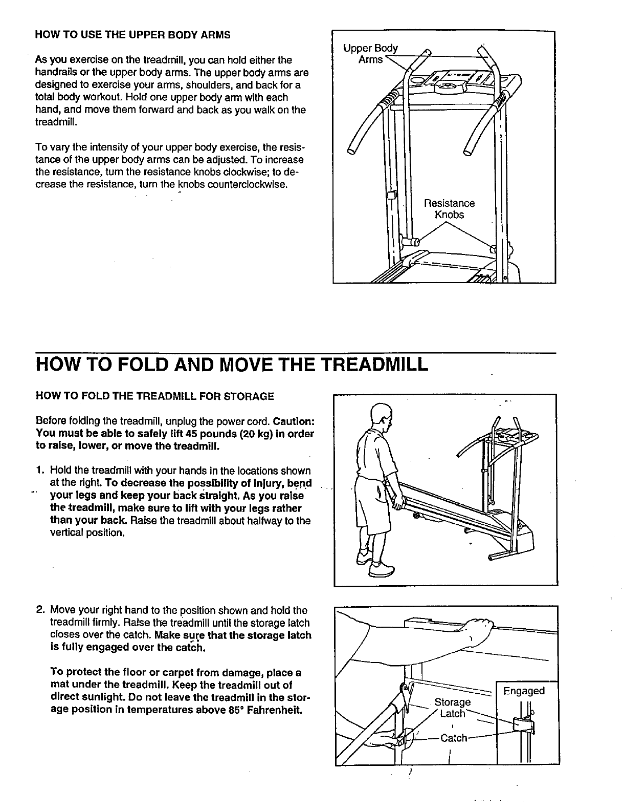
HOW TO USE THE UPPER BODY ARMS
As you exercise on the treadmill, you can hold either the
handrails or the upper body arms. The upper body arms are
designed to exercise your arms, shoulders, and back for a
total body workout. Hold one upper body arm with each
hand, and move them forward and back as you walk on the
treadmill.
To vary the intensity of your upper body exercise, the resis-
tance of the upper body arms can be adjusted. To increase
the resistance, turn the resistance knobs clockwise; to de-
crease the resistance, turn the knobs counterclockwise.
Upper Body
HOW TO FOLD AND MOVE THE TREADMILL
HOW TO FOLD THE TREADMILL FOR STORAGE
Before folding the treadmill, unplug the power cord. Caution:
You must be able to safely lift 45 pounds (20 kg) in order
to raise, lower, or move the treadmill.
1. Hold the treadmill with your hands in the locations shown
at the dght. To decrease the posslb!lity of injury, bend
"' your legs and keep your back straight. As you ralse
the -treadmill, make sure to lift with your legs rather
than your back. Raise the treadmill about halfway to the
vertical position.
2. Move your right hand to the position shown and hold the
treadmill firmly. Raise the treadmill until the storage latch
closes over the catch. Make sure that the storage latch
is fully engaged over the catch.
To protect the floor or carpet from damage, place a
mat under the treadmill. Keep the treadmill out of
direct sunlight. Do not leave the treadmill in the stor-
age position in temperatures above 85°Fahrenheit.
,,
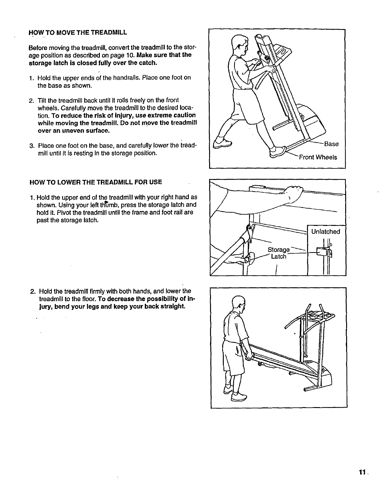
HOW TO MOVE THE TREADMILL
Before moving the treadmill, convert the treadmill to the stor-
age positron as described on page 10. Make sure that the
storage latch is closed fully over the catch.
1. Hold the upper ends of the handrails. Place one foot on
the base as shown.
2. Tilt the treadmill back until it rolls freely on the front
wheels. Carefully move the treadmill to the desired loca-
tion. To reduce the risk of injury, use extreme caution
while moving the treadmill. Do not move the treadmill
over an uneven surface.
3. Place one foot on the base, and carefully lower the iread-
mill until it is resting in the storage position.
Base
els
HOW TO LOWER THE TREADMILL FOR USE
1. Hold the upper end of the treadmill with your right hand as
shown. Using your left thumb, press the storage latch and
hold it. Pivot the treadmill until the frame and foot rail are
past the storage latch.
2. Hold the treadmill firmly with both hands, and lower the
treadmill to the floor. To decrease the possibility of In-
jury, bend your legs and keep your back straight.
11.
TROUBLE-SHOOTING
Most treadmill problems can be solved by following the simple steps below. Find the symptom that
applies, and follow the steps listed. If further assistance is needed, call our toll-free HELPLINE at
1-800-736-6879, Monday through Saturday, 7 a.m. until 7 p.m. Central Time (excluding holidays).
1. SYMPTOM: THE POWER DOES NOT TURN ON
a. Make sure that the power cord is plugged into a surge suppressor, and that the surge suppressor is plugged
into a properly grounded outlet (see page 7). Use only a single-outlet surge suppressor that is UL 1449
listed as a transient voltage surge suppressor (TVSS). The surge suppressor must have a UL suppressed
voltage rating of 400 volts-or less and a minimum surge dissipation of 450 joules. The surge suppressor
must be electrically rated for 120 volts AC and 15 amps. Important: The treadmill is not compatible with
GFCl-equipped outlets.
b. After the power cord has been plugged in, make sure that the key is fully inserted into the console.
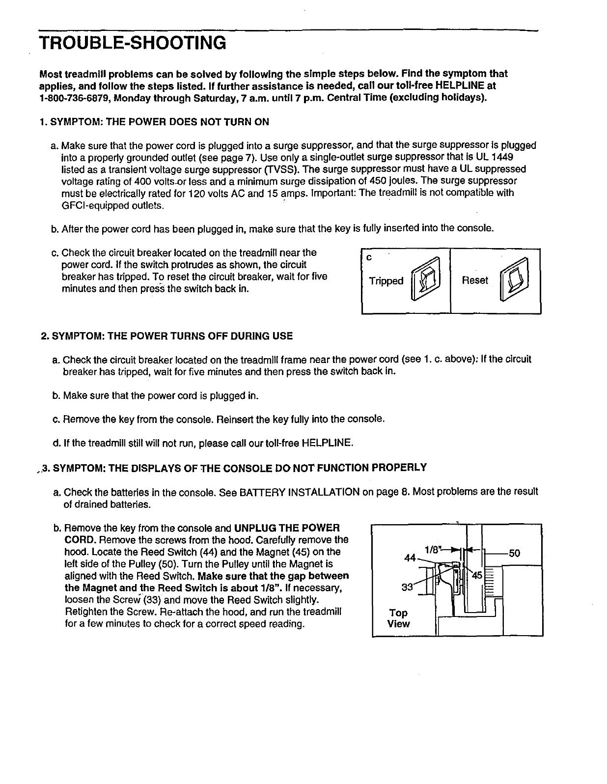
c. Check the circuit breaker located on the treadmill near the
power cord. If the switch protrudes as shown, the circuit
breaker has tripped. To reset the circuit breaker, wait for five
minutes and then press the switch back in. Tripped Reset
2. SYMPTOM: THE POWER TURNS OFF DURING USE
a. Check the circuit breaker located on the treadmill frame near the power cord (see 1. c. above); If the circuit
breaker has tripped, wait for five minutes and then press the switch back in.
b. Make sure that the power cord is plugged in.
c. Remove the key from the console. Reinsert the key fully into the console.
d. If the treadmill stillwill not run, please call our toll-free HELPLINE.
o.3. SYMPTOM: THE DISPLAYS OF THE CONSOLE DO NOT FUNCTION PROPERLY
a. Check the batteries in the console. See BATTERY INSTALLATION on page 8. Most problems are the result
of drained batteries.
b. Remove the key from the console and UNPLUG THE POWER
CORD; Remove the screws from the hood. Carefully remove the
hood. Locate the Reed Switch (44) and the Magnet (45) on the
left side of the Pulley (50). Turn the Pulley until the Magnet is
aligned with the Reed Switch. Make sure that the gap between
the Magnet and the Reed Switch is about 1/8". If necessary,
loosen the Screvl (33) and move the Reed Switch slightly.
Retighten the Screw. Re-attach the hood, and run the treadmill
for afew minutes to check for a correct speed reading.
1/8" 11
Top /
View
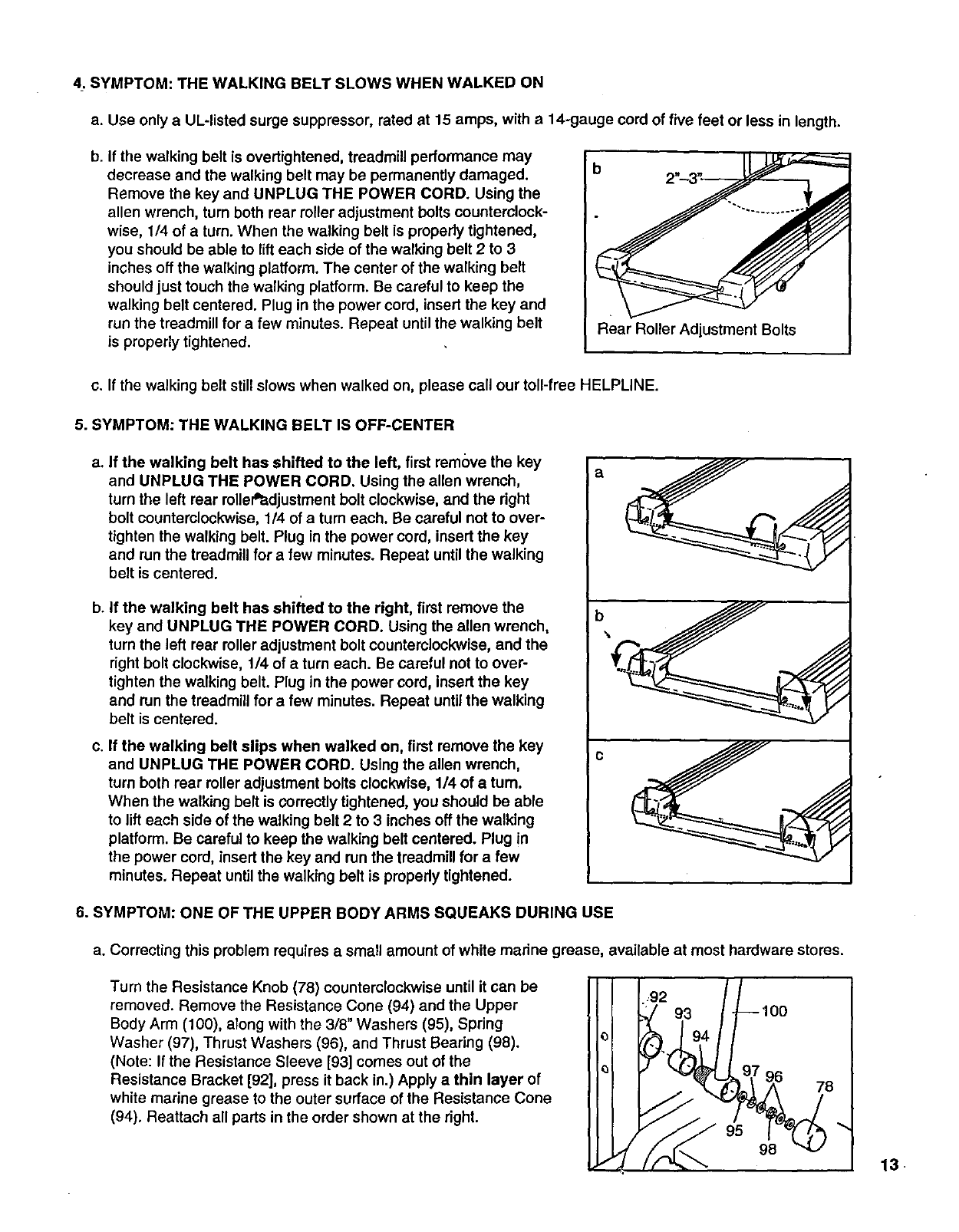
4_.SYMPTOM: THE WALKING BELT SLOWS WHEN WALKED ON
a. Use only a UL-listed surge suppressor, rated at 15 amps, with a 14-gauge cord of five feet or less in length.
b. If the walking belt is overtightened, treadmill performance may
decrease and the walking belt may be permanently damaged.
Remove the key and UNPLUG THE POWER CORD. Using the
allen wrench, turn both rear roller adjustment bolts counterclock-
wise, 1/4 of a turn. When the walking belt is properly tightened,
you should be able to lift each side of the walking belt 2 to 3
inches off the walking platform. The center of the walking belt
should just touch the walking platform. Be careful to keep the
walking belt centered. Plug in the power cord, insert the key and
run the treadmill for a few minutes. Repeat until the walking belt
is properly tightened. Rear Roller Adjustment Bolts
c. If the walking belt still slows when walked on, please call our toll-free HELPLINE.
5. SYMPTOM: THE WALKING BELT IS OFF-CENTER
a. If the walking belt has shifted to the left, first remove the key
and UNPLUG THE POWER CORD. Using the allen wrench,
turn the left rear rollePadjustment bolt clockwise, and the dght
bolt counterclockwise, 1/4 of a turn each. Be careful not to over-
tighten the walking belt. Plug in the power cord, insert the key
and run the treadmill for a few minutes. Repeat until the walking
belt is centered.
b. If the walking belt has shifted to the right, first remove the
key and UNPLUG THE POWER CORD. Using the allen wrench,
turn the left rear roller adjustment bolt counterclockwise, and the
right bolt clockwise, 1/4 of aturn each. Be careful not to over-
tighten the walking belt. Plug in the power cord, insert the key
and run the treadmill for a few minutes. Repeat until the walking
belt is centered.
c. If the walking belt slips when walked on, first remove the key
and UNPLUG THE POWER CORD. Using the allen wrench,
turn both rear roller adjustment bolts clockwise, 1/4 of a turn.
When the walking belt is correctly tightened, you should be able
to lift each side of the walking belt 2 to 3 inches off the walking
platform. Be careful to keep the walking belt centered. Plug in
the power cord, insert the key and run the treadmill for a few
minutes. Repeat untilthe walking belt is propedy tightened.
a
b
C
6. SYMPTOM: ONE OF THE UPPER BODY ARMS SQUEAKS DURING USE
a. Correcting this problem requires a small amount of white madne grease, available at most hardware stores.
Turn the Resistance Knob (78) counterclockwise until it can be rl-T
removed. Remove the Resistance Cone (94) and the Upper
Body Arm (100), along with the 3/8" Washers (95), Spring
Washer (97), Thrust Washers (96), and Thrust Bearing (98).
(Note: If the Resistance Sleeve [93] comes out of the
Resistance Bracket [92], press it back in.) Apply a thin layer of
white marine grease to the outer surface of the Resistance Cone
(94). Reattach all parts in the order shown at the right.
9394 --lOO
13
CONDITIONING GUIDELINES
20 I |_'.J. "4 r,I
40 IL;'- r! ",|
50 I |11 _",!
60 IPIoJ ._, ._f
80 I IZl JI )l.
4
The following guidelines will help you to plan your ex-
ercise program. RememberS-these are general guide-
lines only. For more detailed exercise information, ob- "
tain a reputable book or consult your physician.
EXERCISE INTENSITY
Whether your goal is toburnfat or to strengthen your
cardiovascular system, thekey to achieving the de-
sired results is to exercise with the proper intensity.
The proper intensity level can be found by using your
heart rate as a guide. The chart below shows recom-
mended heart rates for fat burning and aerobic exer-
cise.
HEART RATE TRAINING ZONE
C20 "4
(, 40 rr
(so ,_
(, 60 ,'t.
(, 70 /f
C80 ]y
r,!
,,|
"1
"1
To find the proper heart rate for you, first find your age
on the left side of the chart (ages are rounded off to
the nearest ten years). Next, find the three numbers to
the right of your age. The three numbers are your
"training zone." The lower two numbers are recom-
mended heart rates for fat burning; the higher number
is the recommended heart rate for aerobic exercise.
Fat Burning
To burn fat effectively, you must exercise at a relatively
low intensity level for a sustained period of time. During
the first few minutes of exercise, your body uses easily
accessible carbohydrate calories for energy. Only after
the first few minutes does your bedy begin to use
stored fat calories for energy. If your goal is to bum fat,
adjust the speed and incline of the treadmill until your
heart rate is nea_"one of the lower two numbers in your
training zone. It may also be helpful to set the speed
control on the console to FAT BURN to help you main-
tain the proper intensity level. (See page 9.)
Aerobic Exercise
If your goal is to strengthen your cardiovascular sys-
tem, your exercise must be =aerobic." Aerobic exercise
is activity that requires large amounts of oxygen for
prolonged periods of time. This increases the demand
on the heart to pump.blood to the muscles, and on the
lungs to oxygenate the blood. For aerobic exercise,
adjust the speed and incline of the treadmill until your
heart rate is near the highest number in your training
zone. It may also be helpful to set the speed control on
the console to AEROBIC to help you maintain the
proper intensity level. (See page 9.)
High Performance Athletic Conditioning
If your goal is high performance athletic conditioning,
set the speed control on the console to PERFOR-
MANCE to help you maintain the proper intensity level.
(See page 9.) Note: During the first few weeks of your
exercise program, keep your heart rate near the low
end of'your training zone.
HOW TO MEASURE YOUR HEART RATE
To measure your
heart rate, stop ex-
ercising and place
two fingers on
•,your wrist as
shown, Take a six-
second heartbeat
count, and multiply
the result by ten to
find your heart
•rate. {A six-second count is used because your heart
rate drops quickly when you stop exemising.) If your
heart rate is too high or too low, adjust the speed or in-
cline of the treadmill accordingly.
WORKOUT GUIDELINES
Awell-rounded workout includes the following three
important pads:
A Warm-up
Start each workout with 5 to 10 minutes of stretching
and light exercise (see SUGGESTED STRETCHES on
page 15). A proper warm-up increases your body
temperature, heart rate, and circulation in preparation
for exercise.
T.raining Zone Exercise
After warming up, increase the intensity of your exer-
cise until your pulse is in your training zone for 20 to
60 minutes. (During the first few weeks of your exer-
cise program, do not keep your pulse in your training
zone for longer than 20 minutes.) Breathe regularly
and deeply as you exercise--never hold your breath.
A Cool-down
Finish each workout with 5 to 10 minutes of stretching
to cool down. This will increase the flexibility of your
muscles and will help to prevent post-exercise problems.
Exercise Frequency
To maintain or improve your condition, complete three
workouts each week, with at least one day of rest be-
tween workouts./_.fter a few months, you may com-
plete up to five workouts each week if desired.
The key to success is to make exercise a regular and
enjoyable part of your everyday life.
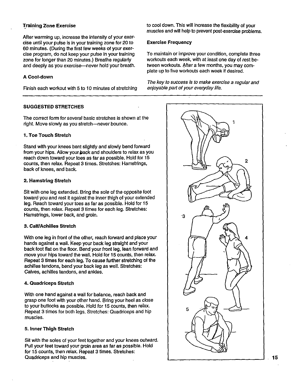
SUGGESTED STRETCHES
The correct form for several basic stretches is shown at the
right. Move slowly as you stretch--never bounce.
1. Toe Touch Stretch
Stand with your knees bent slightly and slowly bend forward
from your hips. Allow your#ack and shoulders to relax as you
reach down toward your toes as far as possible. Hold for 15
counts, then relax. Repeat 3times. Stretches: Hamstrings,
back of knees, and back.
2. Hamstring Stretch
Sit with one leg extended. Bring the sole of the opposite foot
toward you and rest it against the inner thigh of your extended
leg. Reach toward your toes as far as possible. Hold for 15
counts, then relax. Repeat 3 times for each leg. Stretches:
Hamstrings, lower back, and groin.
3. Calf/Achilles Stretch
With one leg in front of the other, reach forward and place your
hands against a wall. Keep your back leg straight and your
back foot flat on the floor. Bend your front leg, lean forward and
move your hips toward the wall. Hold for 15 counts, then relax.
Repeat 3 times for each leg. To cause further stretching of the
achilles tendons, bend your back leg as well. Stretches:
Calves, achilles tendons, and ankles.
4. Quadriceps Stretch
With one hand against a wall for balance, reach back and
grasp one foot with your other hand. Bdng your heel as close
to your buttocks as possible. Hold for 15 counts, then relax.
Repeat 3 times for both legs. Stretches: Quadriceps and hip
muscles.
5. Inner Thigh Stretch
Sit with the soles of your feet together and your knees outward.
Pull your feet toward your groin area as far as possible. Hold
for 15 counts, then relax. Repeat 3 times. Stretches:
Quadriceps and hip muscles.
-3
2
4
15
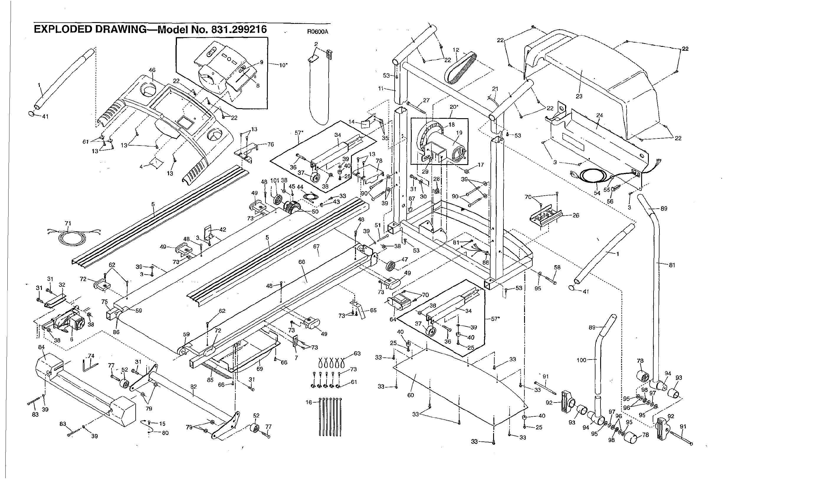
EXPLODED DRAWING--Model No. 831.299216
46
13
49
5
71
62
83
59
85
82
69
3_
52
57*
38 45 44
&'_66
77
R0600A
2
.- 4
34
48 {"
51
67
\
68
-; 73
73_'_ 65",
73 49
j63
7 73
53 j"
f"
4O
12
27 _'"
r 20*
j*
6O
j"
f"
21
23
24
_53
'91 100 8_
3_--4 L--33
93
25 94
98
22
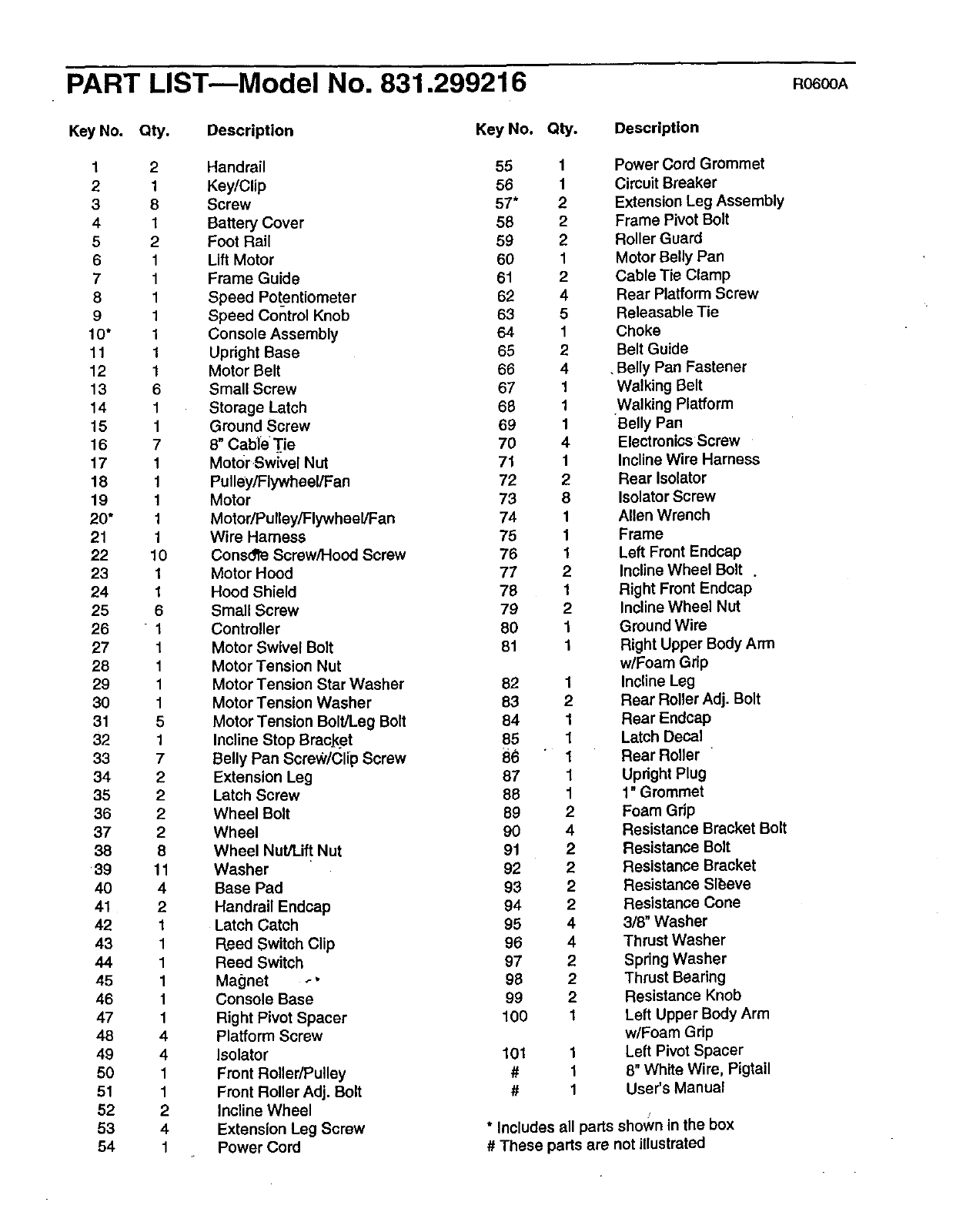
PART LIST--Model No. 831.299216 RO6OOA
Key No. Qty. Description
1 2 Handrail
2 1 Key/Clip
3 8 Screw
4 1 Battery Cover
5 2 Foot Rail
6 1 Lift Motor
7 1 Frame Guide
8 1 Speed Potentiometer
9 1 Speed Control Knob
1O* 1 Console Assembly
11 1 Upright Base
12 1 Motor Belt
13 6 Small Screw
14 1 Storage Latch
15 1 Ground Screw
16 7 8" Cable Tie
17 1 Motor Swivel Nut
18 1 Pulley/Flywheel/Fan
19 1 Motor
20* 1 Motor/Pulley/Flywheel/Fan
21 1 Wire Harness
22 10 Consdlfe Screw/Hood Screw
23 1 Motor Hood
24 1 Hood Shield
25 6 Small Screw
26 " 1 Controller
27 1 Motor Swivel Bolt
28 1 Motor Tension Nut
29 1 Motor Tension Star Washer
30 1 Motor Tension Washer
31 5 Motor Tension Bolt/Leg Bolt
32 1 Incline Stop BracJ_et
33 7 Belly Pan Screw/Clip Screw
34 2 Extension Leg
35 2 Latch Screw
36 2 Wheel Bolt
37 2 Wheel
38 8 Wheel Nut/Lift Nut
39 11 Washer
40 4 Base Pad
41 2 Handrail Endcap
42 1 Latch Catch
43 1 Reed Switch Clip
44 1 Reed Switch
45 1 Magnet _ •
46 1 Console Base
47 1 Right Pivot Spacer
48 4 Platform Screw
49 4 Isolator
50 1 Front Roller/Pulley
51 1 Front Roller Adj. Bolt
52 2 Incline Wheel
53 4 Extension Leg Screw
54 1 Power Cord
Key No. Qty. Description
55 1
56 1
57* 2
58 2
59 2
60 1
61 2
62 4
63 5
64 1
65 2
66 4
67 1
68 1
69 1
70 4
71 1
72 2
73 8
74 1
75 1
76 1
77 2
78 1
79 2
80 1
81 1
82
83
84
85
86
87
88
89
90
91
92
93
94
95
96
97
98
99
100
101
#
#
1
2
1
1
1
1
1
2
4
2
2
2
2
4
4
2
2
2
1
1
1
1
Power Cord Grommet
Circuit Breaker
Extension Leg Assembly
Frame Pivot Bolt
Roller Guard
Motor Belly Pan
Cable Tie Clamp
Rear Platform Screw
Releasable Tie
Choke
Belt Guide
. Belly Pan Fastener
Walking Belt
Walking Platform
Belly Pan
Electronics Screw
Incline Wire Harness
Rear Isolator
Isolator Screw
Allen Wrench
Frame
Left Front Endcap
Incline Wheel Bolt .
Right Front Endcap
Incline Wheel Nut
Ground Wire
Right Upper Body Arm
w/Foam Grip
Incline Leg
Rear Roller Adj. Bolt
Rear Endcap
Latch Decal
Rear Roller
Upright Plug
1" Grommet
Foam Grip
Resistance Bracket Bolt
Resistance Bolt
Resistance Bracket
Resistance Sleeve
Resistance Cone
3/8" Washer
Thrust Washer
Spring Washer
Thrust Bearing
Resistance Knob
Left Upper Body Arm
w/Foam Grip
Left Pivot Spacer
8" White Wire, Pigtail
User's Manual
/
*Includes all parts shown in the box
#These parts are not illustrated
S£ARS
Model No. 831.299216
QUESTIONS?
If you find that:
• you need help assemb!ihg or
operating the PROFORM
CROSSWALK XL treadmill
•a part is missing
•or you need to schedule repair
service
call our toll-free HELPLINE
1-800-736-6879
Monday-Saturday, 7 aRI-7 pm
Central Time (excluding holidays)
REPLACEMENT
PARTS
If parts become worn and need
to be replaced, call the following
toll-free number
1-800-FON-PART
(1-800-366-7278)
The model number and serial number of your PROFORM •
CROSSWALK XL treadmill are listed on adecal attached to the
frame. See the front cover of this manual to find the location of the
decal.
All replacement parts are available for immediate purchase or
special order when you visit your nearest SEARS Service Center.
To request service or to order parts by telephone, call the toll-free
numbers listed at the left.
When requesting help or service, or ordering parts, please be
prepared to provide the following information:
• The NAME OF THE PRODUCT (PROFORM ®CROSSWALK XL
treadmill)
•The MODEL NUMBER OFTHE PRODUCT (831.299216)
•The KEY NUMBER AND DESCRIPTION OF THE PART (see the
EXPLODED DRAWING and PART LIST in the center of this
manual).
FULL 90 DAY WARRANTY
For 90 days from the date of purchase, if failure occurs due to defect in material or workmanship in this
SEARS TREADMILL EXERCISER, contact the nearest SEARS Service Center throughout the United
States and SEARS .will repairor replace the TREADMILL EXERCISER, free of charge.
This warranty does not apply when the TREADMILL EXERCISER is used commercially or for rental pur-
poses.
This warranty gives you specific legal rights, and you may also have other rights which vary from state
to state.
SEARS, ROEBUCK AND CO., DEPT. 817WA, HOFFMAN ESTATES, IL 60179
Part No. 165862 R0600A Printed in USA ©2000 Sears, Roebuck and Co.
