Proform 831299282 User Manual 830QT Manuals And Guides L0020028
PROFORM Treadmill Manual L0020028 PROFORM Treadmill Owner's Manual, PROFORM Treadmill installation guides
830QT L0020028
User Manual: Proform 831299282 831299282 PROFORM PROFORM 830QT - Manuals and Guides View the owners manual for your PROFORM PROFORM 830QT #831299282. Home:Fitness Equipment Parts:Proform Parts:Proform PROFORM 830QT Manual
Open the PDF directly: View PDF ![]() .
.
Page Count: 26
PRO'FORM'83oQTg
I I1'111II III
Ltl
U:
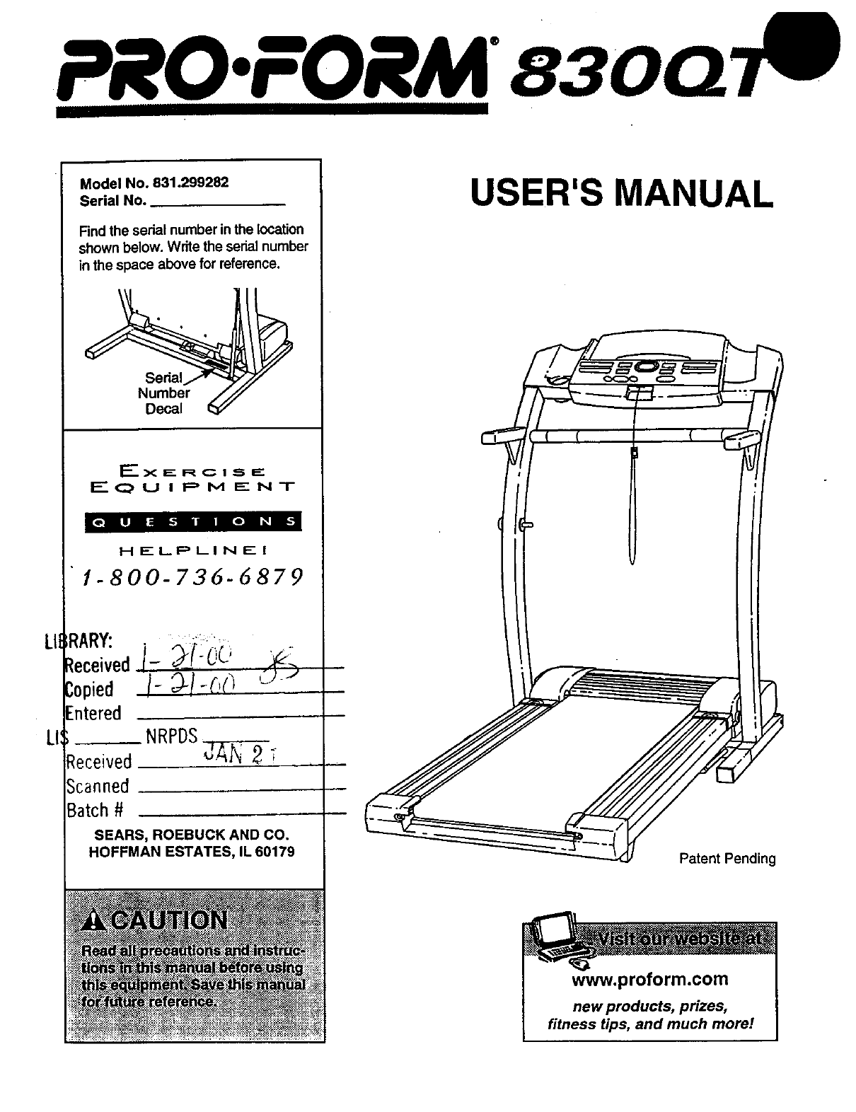
Model No• 831•299282
Serial No.
Find the serial number inthe location
shown below. Write the serial number
in the space above for reference.
Number ///
Decal
E_xERcfS_
F---OU I PM ENT
_[o i_8ai s-mr m i:.,m _w..1
HELPLINE|
]-800-736-6879
RARY: '
_eceived,i- _i:_i_; _,_
/-Copied _/_,/.)(] ':) J
Entered
NRPDS
Received dA]_ _
Scanned. ,
Batch #
SEARS, ROEBUCKANDCO.
HOFFMAN ESTATES, IL 60179
USER'S MANUAL
Patent Pending
www, proform.com
new products, prizes,
fitness tips, and much more!

PRO.FORM83OQT
TABLE OF CONTENTS
IMPORTANT PRECAUTIONS ................................................................. 3
BEFORE YOU BEGIN ....................................................................... 5
ASSEMBLY ............................................................................... 6
OPERATION AND ADJUSTMENT ............................................................. 8
HOW TO FOLD AND MOVE THE TREADMILL .................................................. 19
TROUBLE-SHOOTING ..................................................................... 20
CONDITIONING GUIDELINES ............................................................... 22
PART LIST ............................................................................... 23
ORDERING REPLACEMENT PARTS .................................................. Back Cover
FULL 90-DAY WARRANTY ........................................................... Back Cover
Note: An EXPLODED DRAWING is attached in the center of this manual.
2

IMPORTANT PRECAUTIONS
is Iplacing objects under the treadmill,
3
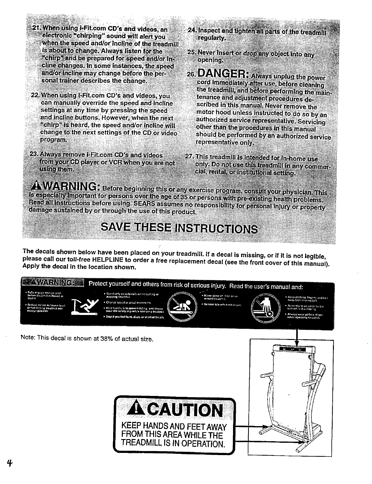
The decals shown below have been placed on your treadmill. If a decal is missing, or if it is not legible,
please call our toll-free HELPLINE to order a free replacement decal (see the front cover of this manual).
Apply the decal in the location shown.
Note: This decal is shown at 38% of actual sfze.
BEFORE YOU BEGIN
Thank you for selecting the revolutionaly PROFORM •
830QT treadmill. The 830QT treadmill combines ad-
vanced technology with innovative design to help you
get the most from your exercise program in the conve-
nience and privacy of your home. And when you're not
exercising, the unique 830QT can be folded up, requir-
ing less than half the floor space of other treadmills.
For your benefit, read this manual carefully before
using the treadmill. If you have additional questions,
please call our toll-free HELPLINE at 1-800-736-6879,
Monday through Saturday, 7 a.m. until 7 p.m. Central
Time (excluding holidays). To help us assist you,
please note the product model number and serial num-
ber before calling. The model number of the treadmill
is 831.299282. The serial number can be found on a
decal attached to the treadmill (see the front Cover of
this manual for the location).
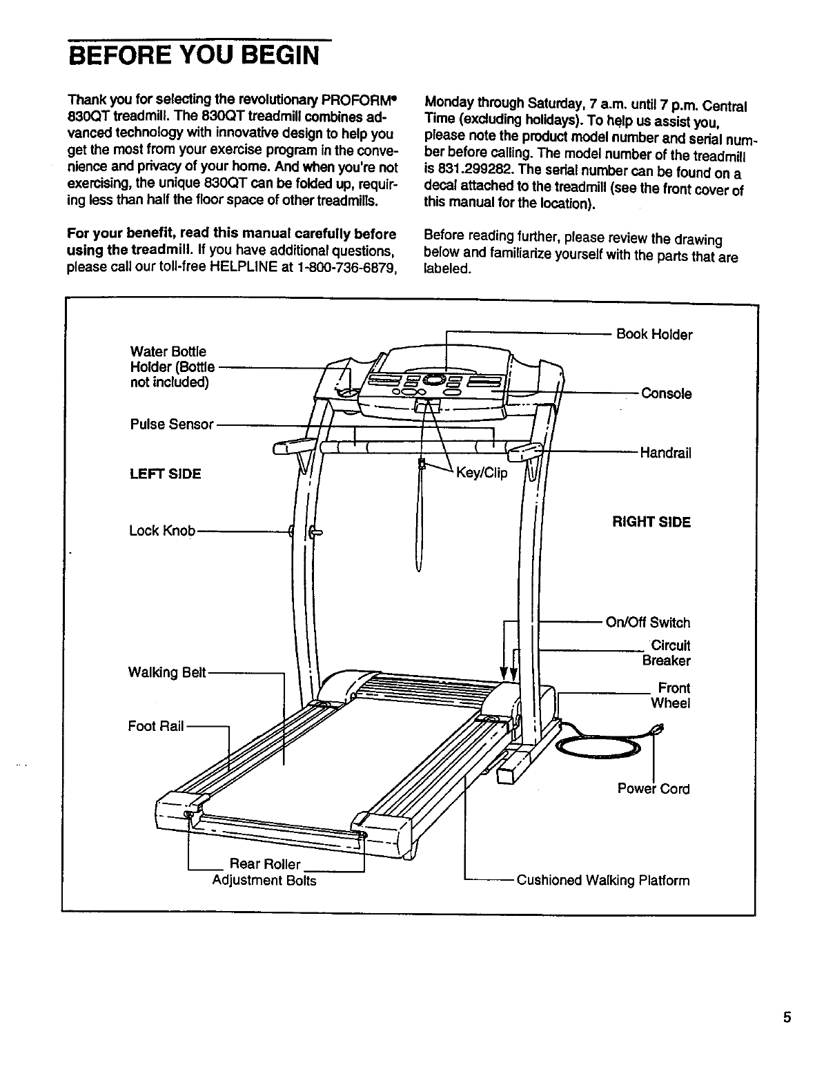
Before reading further, please review the drawing
below and familiarize yourself with the parts that are
labeled.
Water Bottle
Holder (Bottle
not included)
Pulse Senso=
LEFT SIDE
Lock Knob
Walking Belt
Book Holder
Console
Handrail
RIGHT SIDE
On/Off Switch
Circuit
Breaker
Front
Wheel
Rear Roller
Adjustment Bolts
Powe J
-- Cushioned Walking Platform
ASSEMBLY
Assembly requires two people. Set the treadmill in a cleared area and remove all packing materials. Do not
dispose of the packing materials until assembly is completed. Assembly requires the included allen wrench_
and your own phillips screwdriver _i_ '===_" •
Note: The underside of the treadmill walking belt is coated with high-performance lubricant. During shipping, a
small amount of lubricant may be transferred to the top of the walking belt or the shipping carton. This is a normal
condition and does not affect treadmill performance. If there is lubricant on top of the walking belt, simply wipe off
the lubricant with asoft cloth and a mild, non-abrasive cleaner.
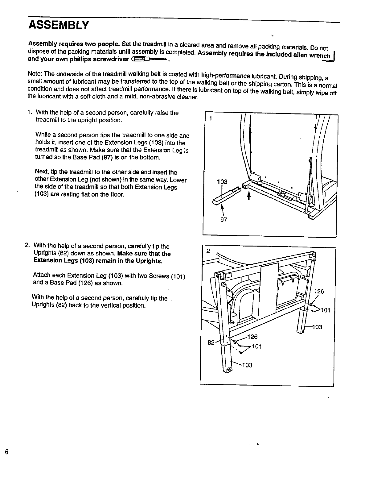
1. With the help of a second person, carefully raise the
treadmill to the upright position.
While a second person tips the treadmill to one side and
holds it, insert one of the Extension Legs (103) into the
treadmill as shown. Make sure that the Extension Leg is
turned so the Base Pad (97) is on the bottom.
Next, tip the treadmill to the other side and insert the
other Extension Leg (not shown) in the same way. Lower
the side of the treadmill so that both Extension Legs
(103) are resting flat on the floor.
1
97
2. With the help of a second person, carefully tip the
Uprights (82) down as shown. Make sure that the
Extension Legs (103) remain in the Uprights.
Attach each Extension Leg (103) with two Screws (101)
and a Base Pad (126) as shown.
With the help of asecond person, carefully tip the
Uprights (82) back to the vertical position.
.101
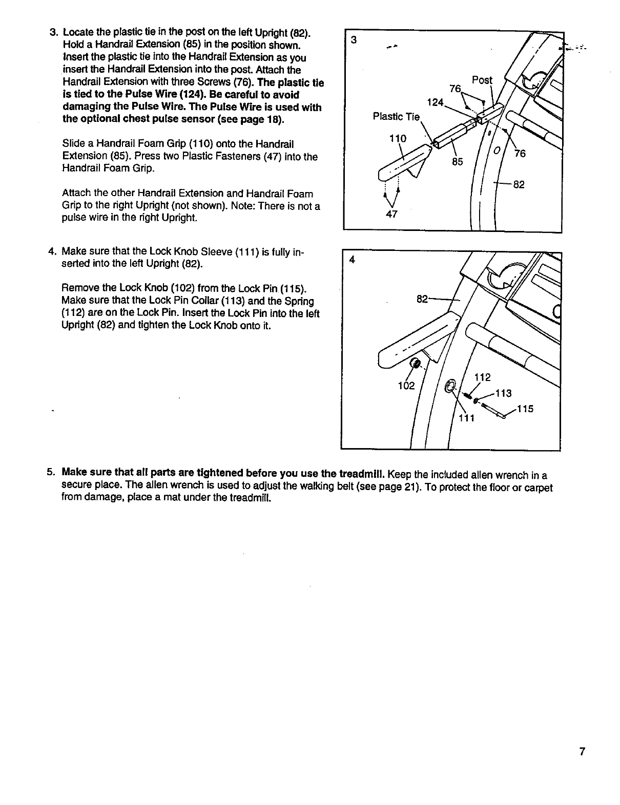
3. Locate the plastic tie in the post on the left Updght (82).
Hold a Handrail Extension (85) in the position shown.
Insed the plastic tie into the Handrail Extension as you
insed the Handrail Extension into the post. Attach the
Handrail Extension with three Screws (76). The plastic tie
is tied to the Pulse Wire (124). Be careful to avoid
damaging the Pulse Wire. The Pulse Wire is used with
the optional chest pulse sensor (see page 18).
Slide a Handrail Foam Grip (110) onto the Handrail
Extension (85). Press two Plastic Fasteners (47) into the
Handrail Foam Grip.
Attach the other Handrail Extension and Handrail Foam
Grip to the right Upright (not shown). Note: There is not a
pulse wire in the right Upright.
3
Plastic Tie
110
47
76
124_
Post
85
4. Make sure that the Lock Knob Sleeve (111 ) is fully in-
sealed into the left Updght (82).
Remove the Lock Knob (102) from the Lock Pin (115).
Make sure that the Lock Pin Collar (113) and the Spdng
(112) are on the Lock Pin. Insert the Lock Pin into the left
Upright (82) and tighten the Lock Knob onto it.
4
102
5. Make sure that all parts are tightened before you use the treadmill. Keep the included allen wrench in a
secure place. The allen wrench is used to adjust the walking belt (see page 21). To protect the floor or carpet
from damage, place a mat under the treadmill.
7
OPERATION AND ADJUSTMENT
THE PERFORMANT LUBE TM WALKING BELT
Your treadmill features awalking belt coated with
PERFORMANT LUBE TM, ahigh-performance lubricant.
IMPORTANT: Never 0pply silicone spray or other
substances to the walking belt or the walking plat-
form. Such substances will deteriorate the walking
belt and cause excessive wear.
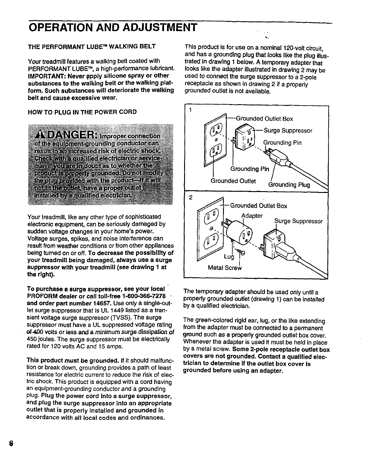
This product is for use on a nominal 120-volt circuit,
and has agrounding plug that looks like the plug illus-
trated in drawing 1 below. A temporary adapter that
looks like the adapter illustrated in drawing 2 may be
used to connect the surge suppressor to a 2-pole
receptacle as shown in drawing 2 if aproperly
grounded outlet is not available.
HOW TO PLUG IN THE POWER CORD
Your treadmill, like any other type of sophisticated
electronic equipment, can be seriously damaged by
sudden voltage changes in your home's power.
Voltage surges, spikes, and noise interference can
result from weather conditions or from other appliances
being turned on or off. To decrease the possibility of
your treadmill being damaged, always use a surge
suppressor with your treadmill (see drawing 1 at
the right).
To purchase a surge suppressor, see your local "
PROFORM dealer or call toll-free 1-800-366-7278
and order part number 14657. Use only a single-out-
let surge suppressor that is UL 1449 listed as a tran-
sient voltage surge suppressor (TVSS), The surge
suppressor must have a UL suppressed voltage rating
• _fA_0 volts or less and a minimum .surgedissipation of
450 joules. The surge suppressor must be electrically
rated for 120 volts AC and 15 amps.
This product must be grounded. If it should malfunc-
tion or break down, grounding provides a path of least
resistance for electric current to reduce the risk of elec-
tric shock. This product is equipped with a cord having
an equipment-grounding conductor and a grounding
plug. Plug the power cord into a surge suppressor,
and plug the surge suppressor into an appropriate
outlet that is properly installed and grounded in
accordance with all local codes and ordinances.
i ]_.l__ sOUti_ sBu°ppressor
i°_" "_... GrOunding Pin
Grounding P_
Grounded Outlet (_rounding Plug"_
2
Grounded Outlet Box
pter Surge Suppressor
The temporary adapter should be used only until a
properly grounded outlet (drawing 1) can be installed
by a qualified electrician.
The green-colored rigid ear, lug, or the like extending
from the adapter must be connected to apermanent
ground such as a properly grounded outlet box cover,
Whenever the adapter is used it must be held in place
by a metal screw. Some 2-pole receptacle outlet box
covers are not grounded. Contact a qualified elec-
trician to determine if the outlet box cover is
grounded before using an adapter.
8
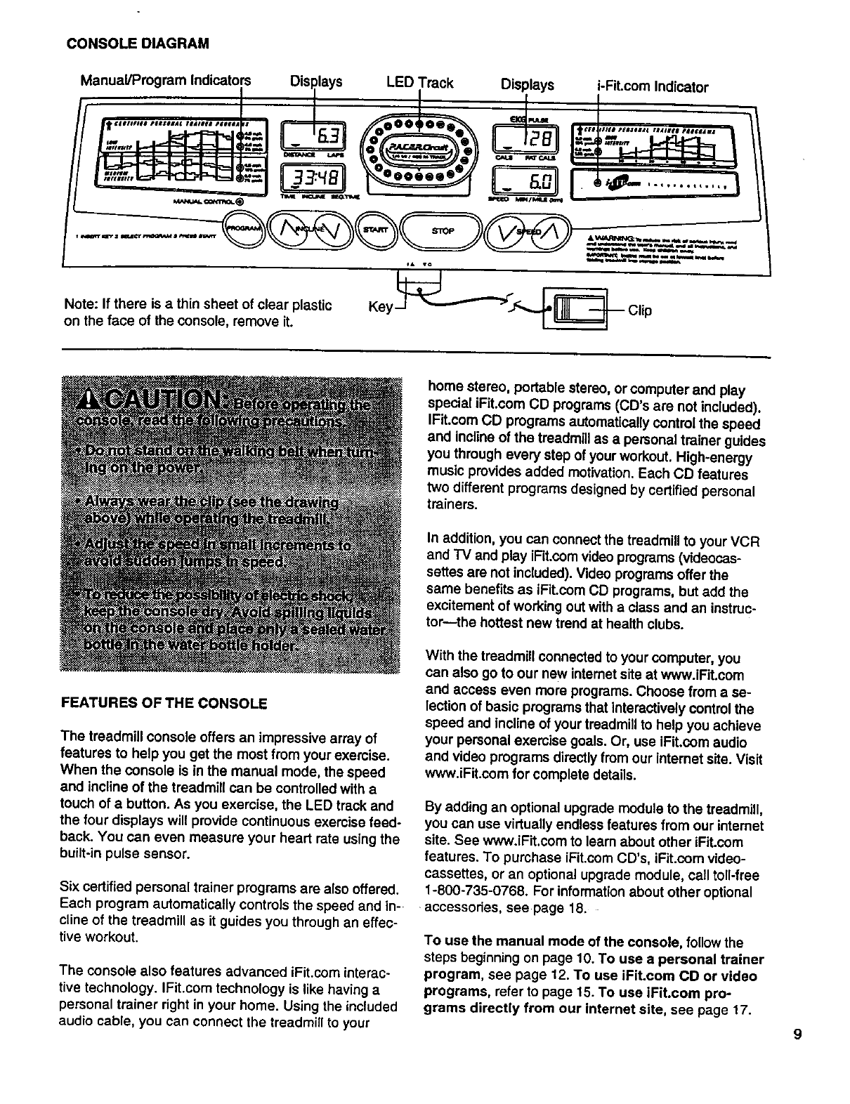
CONSOLEDIAGRAM
Manual/Program Indicators Displays LED Track Displays i-Fit.com Indicator
. ,.............
Note.-if there is athin sheet of clear plastic Key___ Clip
on the face of the console, remove it.
home stereo, portable stereo, or computer and play
special iFit.com CD programs (CD's are not included).
IFit.com CD programs automatically control the speed
and incline of the treadmill as a personal trainer guides
you through every step of your workout. High-energy
music provides added motivation. Each CD features
two different programs designed by certified personal
trainers.
In addition, you can connect the treadmill to your VCR
and TV and play iFit.com video programs (videocas-
settes are not included). Video programs offer the
same benefits as iFit.com CD programs, but add the
excitement of working out with a class and an instruc-
tor-the hottest new trend at health clubs.
FEATURES OF THE CONSOLE
The treadmill console offers an impressive array of
features to help you get the most from your exercise.
When the console is in the manual mode, the speed
and incline of the treadmill can be controlled with a
touch of abutton. As you exercise, the LED track and
the four displays will provide continuous exercise feed-
back. You can even measure your heart rate using the
built-in pulse sensor.
Six certified persona[ trainer programs are also offered.
Each program automatically controls the speed and in-
cline of the treadmill as it guides you through an effec-
tive workout.
The console also features advanced iFit.com interac-
tive technology. IFit.com technology is like having a
personal trainer right in your home. Using the included
audio cable, you can connect the treadmill to your
With the treadmill connected to your computer, you
can also go to our new intemet site at wwwJFit.com
and access even more programs. Choose from a se-
lection of basic programs that interactively control the
speed and incline of your treadmill to help you achieve
your personal exercise goals. Or, use iFit.com audio
and video programs directly from our intemet site. Visit
www.iFit.com for complete details.
By adding an optional upgrade module to the treadmill,
you can use virtuatly endless features from our intemet
site. See www.iFit.com to learn about other iFit.com
features. To purchase iFit.com CD's, iFit.com video-
cassettes, or an optional upgrade module, call toll-free
1-800-735-0768. For information about other optional
accessodes, see page 18.
To use the manual mode of the console, follow the
steps beginning on page 10. To use a personal trainer
program, see page 12. To use iFIt.com CD or video
programs, refer to page 15. To use iFit.com pro-
grams directly from our internet site, see page 17.
STEP-BY-STEP CONSOLE OPERATION
Make sure that the on/off
switch near the power
cord is in the on
position. Next, make sure
that the key is removed
from the console and the
OnJ
Position
power cord is properly plugged in (see HOW TO PLUG
IN THE POWER CORD on page 8).
When you are ready to begin exercising, step onto the
foot rails of the treadmill. Find the clip attached to the
• key (see ths drawing on page 9), and slide the clip
onto the waistband of your clothing.
To use the manual mode of the console, follow the
steps below. To use a personal trainer program, see
page 12. To usa iFit.com CD or video programs,
refer to page 15. To use iFit.com programs directly
from our internet site, see page 17.
Note: The console can display speed and distance in
either miles or kilometers (see SPEED/MIN-MILE DIS-
PLAY on page 11). For simplicity, all instructions in this
manual refer to miles,
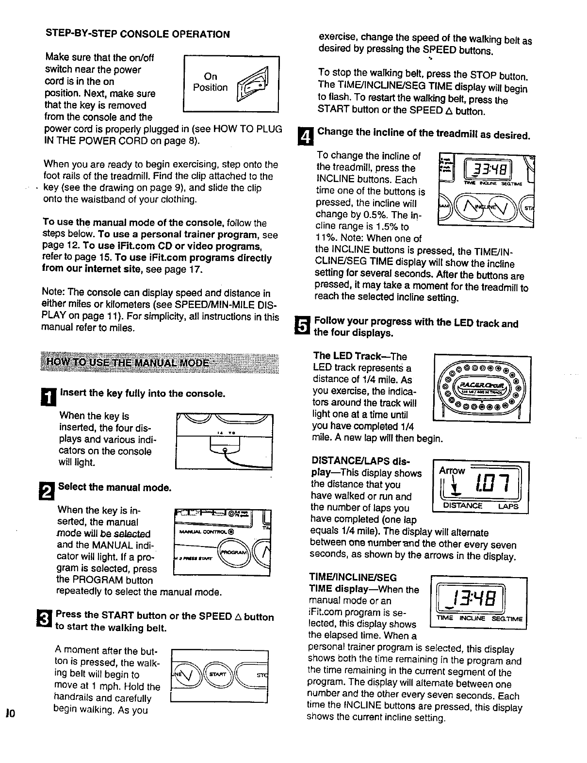
exemise, change the speed of the walking belt as
desired by pressing the SPEED buttons.
To stop the walking belt, press the STOP button.
The TIMF_/INCUNE/SEG TIME display will begin
to flash. To restart the walking belt, press the
START button or the SPEED Z_button.
L_ Change the incline of the treadmill as desired.
To change the incline of
the treadmill, press the
INCLINE buttons. Each
time one of the buttons is
pressed, the incline will
change by 0.5%. The ino
cline range is 1.5% to
11%. Note: When one of
the iNCLINE buttons is pressed, the TIME/IN-
CLINEJSEG TIME display wilt show the incline
setting for several seconds. After the buttons are
pressed, it may take a moment for the treadmill to
reach the selected incline setting.
[]Follow your progress with the LED track and
the four displays.
'• ' _ • _M :_+__ +_.....................
......
B Insert the key fully into the console.
inserted, the four dis-
plays and various indi-
cators on the console
will light.
B
When the key is in-
serted, the manual
mode wUlbe selected
and the MANUAL indi-
cator will light. If a pro-
gram is selected, press
the PROGRAM button
Select the manual mode.
repeatedly to select the manual mode.
!_ Press the START button or the SPEED Abutton
to start the walking belt.
A moment after the but-
ton is pressed, the walk-
ing belt will begin to
move at 1 mph. Hold the
handrails and carefully
begin walking. As you
I
The LED Track--The
LED track represents a
distance of 1/4 mile. As
you exercise, the indica-
tors around the track will
lightone at a time until
you have completed 1/4
mile. A new lap will then begin.
DISTANCF_JLAPS dis- i_
play--This display shows Arrow
have walked or run and
the number of laps you DISTANCE LAP_
have completed (one lap
equals 1/4 mile). The display will alternate
between one number _nd the other every seven
seconds, as shown by the arrows in the display.
t
TIMF_JlNCLINEiSEG
TIME display--When the
manual mode oran 13:4B
iFit.com program is se- "nM_ INCUN_SIEG_TIME
lected, this display shows
the elapsed time. When a
personal trainer program is selected, this display
shows both the time remaining in the program and
the time remaining in the current segment of the
program. The display will alternate between one
number and the other eve_ seven seconds. Each
time the INCLINE buttons are pressed, this display
shows the current incline setting.
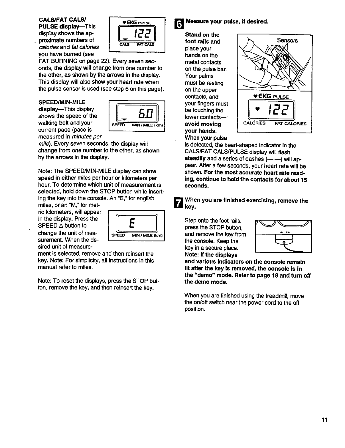
CALS/FAT CALS/
PULSE display--This
display shows the ap-
proximate numbers of
calories and fat calories
you have bumed (see
wEKG
II- 12211
r-AT _a&S
FAT BURNING on page 22). Every seven sec-
onds, the display will change from one number to
the other, as shown by the arrows in the display.
This display will also show your heart rate when
the pulse sensor is used (see step 6 on this page).
SPEED/MIN-MILE
display--This display
shows the speed of the
walking belt and your
current pace (pace is
measured in minutes per
mile). Every seven seconds, the display will
change from one number to the other, as shown
by the arrows in the display.
Note: The SPEED/MIN-MILE display can show
speed in either miles per hour or kilometers per
hour. To determine which unit of measurement is
selected, hold down the STOP button while insert-
ing the key into the console. An =E,"for english
miles, or an "M," for met-
ric kilometers, will appear
in the display. Press the
SPEED L_button to
change the unit of mea-
surement. When the de-
sired unit of measure-
ment is selected, remove and then reinsert the
key. Note: For simplicity, all instructions in this
manual refer to miles.
Note: To reset the displays, press the STOP but-
ton, remove the key, and then reinsert the key.
[]
Stand on the
foot rails and
place your
hands on the
metal contacts
on the pulse bar.
Your palms
must be resting
on the upper
contacts, and
your fingers must
be touching the
lower contacts--
avoid moving
your hands.
When your pulse
Measure your pulse, if desired.
Sensors
3"_ \\
EKG PULSE
- 122
CALORIES FAT CALORIES
is detected, the heart-shaped indicator in the
CALS/FAT CALS/PULSE display will flash
steadily and a series of dashes (----) will ap-
pear. After a few seconds, your heart rate will be
shown. For the most accurate heart rate read-
ing, continue to hold the contacts for about 15
seconds.
B When you are finished exercising, remove the
key.
Step onto the foot rails,
press the STOP button,
and remove the key from
the console. Keep the
key in a secure place.
Note: If the displays
and various indicators on the console remain
lit after the key is removed, the console is In
the "demo" mode, Refer to page 18 and turn off
the demo mode.
When you are finished using the treadmill, move
the on/off switch near the power cord to the off
position.
11
andvadousIndicators
onthe console will light.
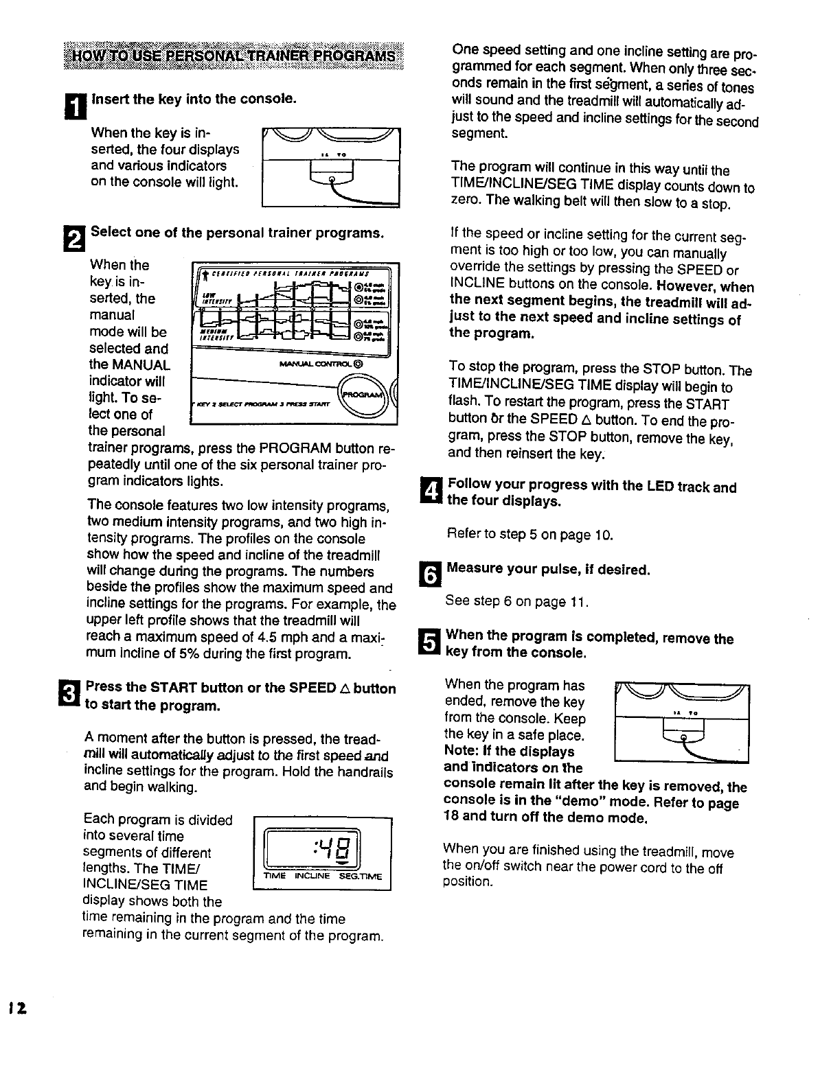
B Insert the key into the console.
wnon
serted, the four displays
Select one of the personal trainer programs.
When the
key is in-
serted, the
manual
mode will be
selected and
the MANUAL
indicator will
light. To se-
lect one of
the personal
,-;,%,,_@,'t.=ll
M_NU_.CO_mOL@
trainer programs, press the PROGRAM button re-
peatedly until one of the six personal trainer pro-
gram indicators lights.
The console features two low intensity programs,
two medium intensity programs, and two high in-
tensity programs. The profiles on the console
show how the speed and incline of the treadmill
will change dudng the programs. The numbers
beside the profiles show the maximum speed and
incline settings for the programs, For example, the
upper left profile shows that the treadmill will
reach a maximum speed of 4.5 mph and a maxi-
mum incline of 5% during the first program.
[]Press the START button or the SPEED/x button
to start the program.
A moment after the button is pressed, the tread-
mill will automaticagy adjust to the first speed and
incline settings for the program. Hold the handrails
and begin walking.
Each program is divided
into several time
segments of different
lengths. The TIME/
INCLINE/SEG TIME
display shows both the
time remaining in the program and the time
remaining in the current segment of the program.
One speed setting and one incline setting are pro-
grammed for each segment. When only three sec-
onds remain in the fhst s_jment, a series of tones
will sound and the treadmill will automatically ad-
just to the speed and incline settings for the second
segment.
The program will continue in this way until the
TIME/INCLINE/SEG TIME display counts down to
zero. The walking belt will then slow to a stop.
If the speed or incline setting for the current seg-
ment is too high or too low, you can manually
override the settings by pressing the SPEED or
INCLINE buttons on the console. However, when
the next segment begins, the treadmill will ad-
just to the next speed and incline settings of
the program.
To stop the program, press the STOP button. The
TIME/INCLINF_JSEG TIME display will begin to
flash. To restart the program, press the START
button t_r the SPEED _ button. To end the pro-
gram, press the STOP button, remove the key,
and then reinsert the key:
L_ Follow your progress with the LED track and
the four displays.
Refer to step 5 on page 10.
r_ Measure your pulse, if desired.
See step 6 on page 11.
_',_ When the program is completed, remove the
key from the console.
When the program has
ended, remove the key
from the console. Keep
the key in a safe place.
Note: If the displays
and indicators on the
console remain lit after the key is removed, the
console is in the "demo" mode. Refer to page
18 and turn off the demo mode.
When you are finished using the treadmill, move
the on/off switch near the power cord to the off
position.
IZ
To use iFit.com CD's, the treadmill must be con-
nected to your portable CD player, portable stereo,
home stereo, or computer with CD player. See pages
13 and 14 for connecting instructions. To use iFit.€om
videocassettes; the treadmill must be connected to
your VCR. See page 15 for connecting instructions. To
use iFit.com programs directly from our internet
site, the treadmill must be connected to your home
computer. See page 14 for connecting instructions.
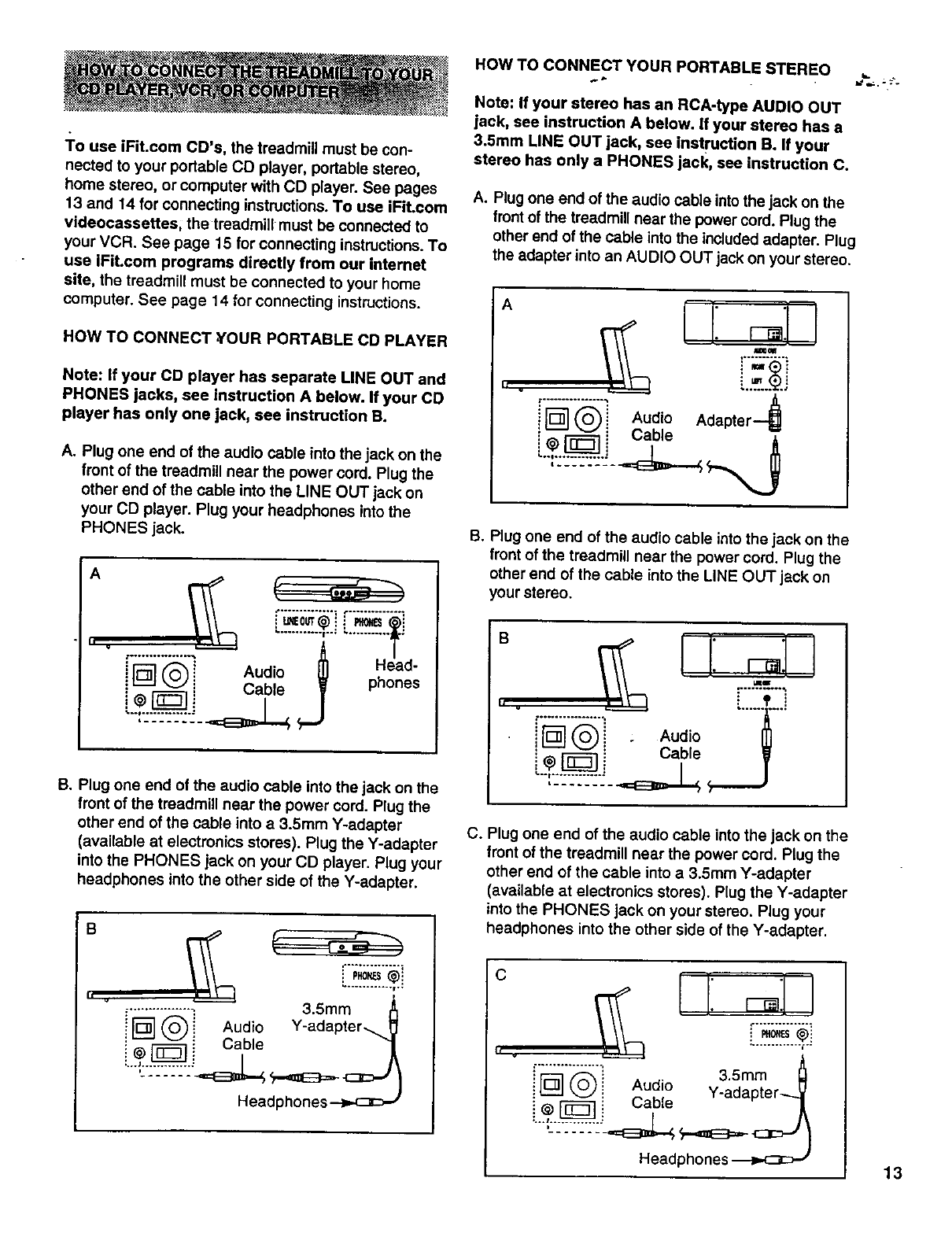
HOW TO CONNECT ,YOUR PORTABLE CD PLAYER
Note: If your CD player has separate LINE OUT and
PHONES jacks, see instruction A below. If your CD
player has only one jack, see instruction B.
A. Plug one end of the audio cable into the jack on the
front of the treadmill near the power cord. Plug the
other end of the cable into the LINE OUT jack on
your CD player. Plug your headphones into the
PHONES jack.
A
iF.
it-_J _ i Cable _ P
B. Plug one end of the audio cable into the jack on the
front of the treadmi;{ near the power cord. Plug the
other end of the cable into a 3.5ram Y-adapter
(available at electronics stores). Plug the Y-adapter
into the PHONES jack on your CD player. Plug your
headphones into the other side of the Y-adapter•
B
i
................_. 3.5mm
i _ _ _ Aud o Y-adapter_
i _ i Cable 1
Headphones-_.<:3c_ r
HOW TO CONNECT YOUR PORTABLE STEREO
Note: If your stereo has an RCA-type AUDIO OUT
jack, see instruction A below, if your stereo has a
3.5ram LINE OUT jack, see instruction B. If your
stereo has only a PHONES jack, see instruction C.
A. Plug one end of the audio cable intothe jack on the
front of the treadmill near the power cord. Plug the
other end of the cable into the includedadapter. Plug
the adapter into an AUDIO OUT jack on your stereo.
A
II .
i'r'_'_! Audio Adapter--_
Oab,o
B. Plug one end of the audio cable into the jack on the
front of the treadmill near the power cord. Plug the
other end of the cable into the LINE OUT jack on
your stereo.
" cU ,,o
C. Plug one end of the audio cable into the jack on the
front of the treadmi{{ near the power cord. Plug the
other end of the cable into a3.5ram Y-adapter
(available at electronics stores). Plug the Y-adapter
into the PHONES jack on your stereo. Plug your
headphones into the other side of the Y-adapter.
C
.................: 3.5mM
i @i Audio
: Cable
Head 13
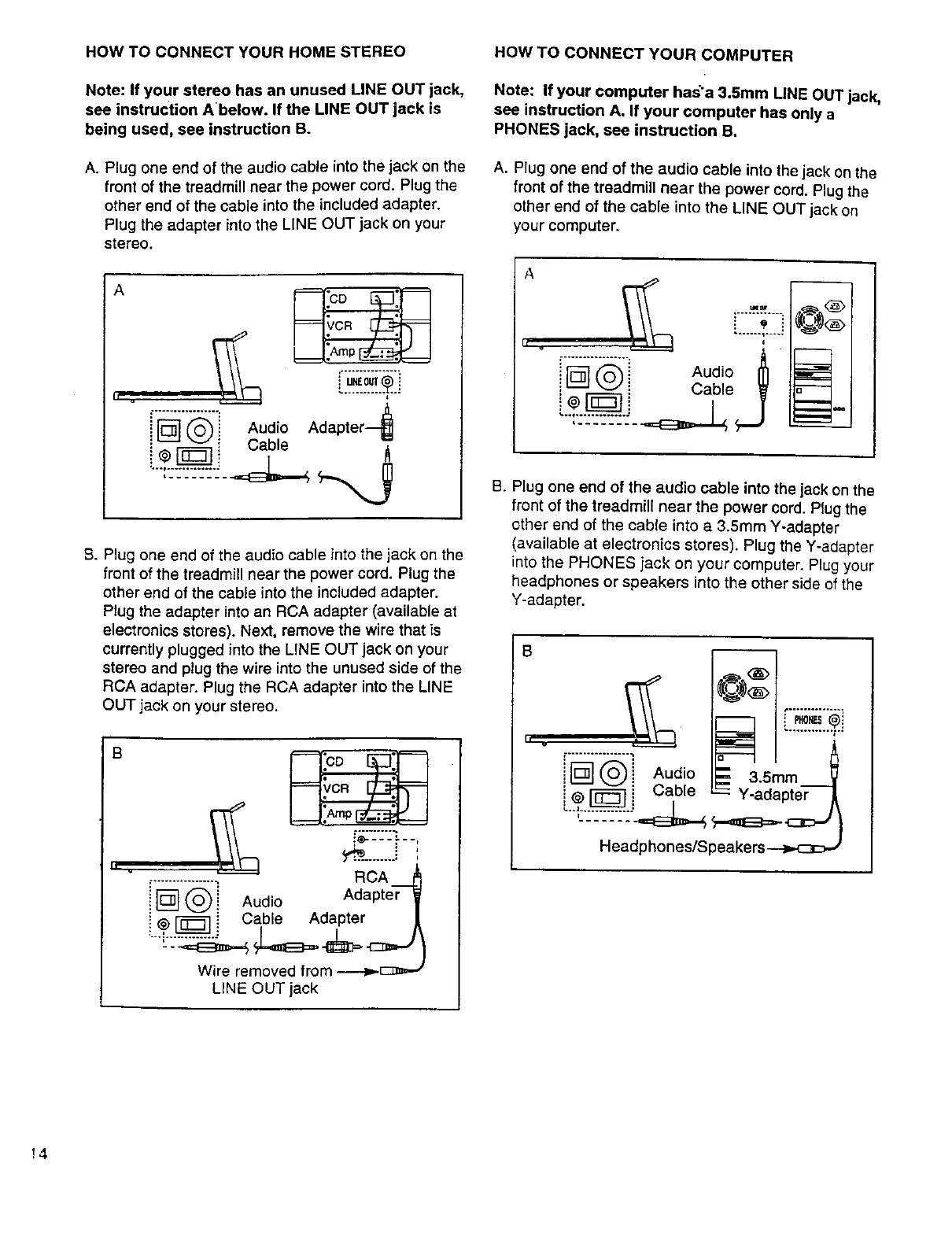
HOW TO CONNECT YOUR HOME STEREO
Note: If your stereo has an unused LINE OUT jack,
see instruction A'below. If the LINE OUT jack is
being used, see instruction B.
A. Plug one end of the audio cable into the jack on the
front of the treadmill near the power cord. Plug the
other end of the cable into the included adapter.
Plug the adapter into the LINE OUT jack on your
stereo.
A
h
t................. 4
i[_'] @ Audio Adapter
Cable
B. Plug one end of the audio cable into the jack on the
front of the treadmill near the power cord. Plug the
other end of the cable into the included adapter.
Plug the adapter into an RCA adapter (available at
electronics stores). Next, remove the wire that is
currently plugged into the LINE OUT jack on your
stereo and plug the wire into the unused side of the
RCA adapter. Plug the RCA adapter into the LINE
OUT jack on your stereo.
B
h u ._................_. RCA
!r_ @i Audio Adapter f
i @ r_ i Cable Adapter._
-- I
Wire removed from ----4_E:_ =-_
LINE OUT jack
HOW TO CONNECT YOUR COMPUTER
Note: If your computer has'a 3.5mm LINE OUT jack,
see instruction A. If your computer has only a
PHONES jack, see instruction B.
A. Plug one end of the audio cable into the jack on the
front of the treadmill near the power cord. Plug the
other end of the cable into the LINE OUT jack on
your computer.
A
II v
_M
CZI
q
i_-"] (_i Audio _
i_ _J i Cable _ -
B. Plug one end of the audio cable into the jack on the
front of the treadmill near the power cord. Plug the
other end of the cable into a 3.5mm Y-adapter
(available at electronics stores). Plug the Y-adapter
into the PHONES jack on your computer. Plug your
headphones or speakers into the other side of the
Y-adapter.
8
h v ,-............... A
iN@] Audio a_'_ 3.Smm_
i @ _ i Cable -_ Y-adapter-_ /
Headphones/Speakers -->,._cJ
!4
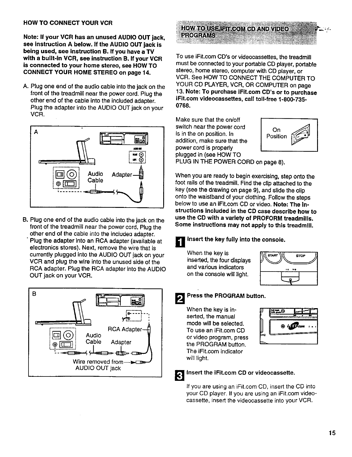
HOW TO CONNECT YOUR VCR
Note: If your VCR has an unused AUDIO OUT jack,
see instruction A below, if the AUDIO OUT jack is
being used, see Instruction B. If you have a TV
with a built-in VCR, see instruction B. If your VCR
is connected to your home stereo, see HOW TO
CONNECT YOUR HOME STEREO on page 14.
A. Plug one end of the audio cable into the jack on the
front of the treadmill near the power cord. Plug the
other end of the cable into the included adapter.
Plug the adapter into the AUDIO OUT jack on your
VCR.
A
ii
IIIJ_
i _ ('_ i Audio Adapter
i@_ i Cable A
B. Plug one end of the audio cable into the jack on the
front of the treadmill near the power cord. Plug the
other and of the cable into the inctudea adapter.
• Plug the adapter into an RCA adapter (available at
electronics stores). Next, remove the wire that is
currently plugged into the AUDIO OUT jack on your
VCR and plug the wire into the unused side of the
RCA adapter. Plug the RCA adapter into the AUDIO
OUT jack on your VCR.
B
h w ._'_"_"_ RCA Adapter--_
!L_J (-0.) i Audio i
i _, _ i Cable Adapter [
L_.._." I/I\
"'---_E3==-._ H<=_3=-_=.-c_mJ }
Wire removed from_
AUDIO OUT jack
To use iFit.com CD's or videocassettes, the treadmill
must be connected to your portable CD player, portable
stereo, home stereo, computer with CD player, or
VCR. See HOW TO CONNECT THE COMPUTER TO
YOUR CD PLAYER, VCR, OR COMPUTER on page
13. Note: To purchase iFit.com CD's or to purchase
iFit.com videocassettes, call toll-free 1-800-735-
0768.
Make sure that the on/off I [_
switch near the power cord On
is in the on position. In Position
addition, make sure that the
power cord is properly
plugged in (see HOW TO
PLUG IN THE POWER CORD on page 8),
When you are ready to begin exercising, step onto the
foot rails of the treadmill. Find the clip attached to the
key (see the drawing on page 9), and slide the clip
onto the waistband of your clothing. Follow the steps
below to use an iFit.com CD or video. Note: The in-
structions included in the CD case describe how to
use the CD with a variety of PROFORM treadmills.
Some instructions may not apply to this treadmill.
When the key is
inserted, the four displays
and various indicators
on the console will light.
g Insert the key fully into the console.
B Press the PROGRAM button.
When the key is in-
serted, the manual
mode will be selected.
To use an iFit.com CD
or video program, press
the PROGRAM button.
The iFit.com indicator
will light.
II
Insert the iFit.com CD or videocassette.
if you are using an iFit.com CD, insert the CD into
your CD player. If you are using an iFit.com video-
cassette, insert the videocassette into your VCR.
15
DP_I_s the PLAY button on your CD p'ayer or
Amoment after the button is pressed, your per-
sonal trainer will begin guiding you through your
workout. Simply follow your personal trainer's
instructions.
During the CD or video program, an electronic
"chirping" sound will alert you when the speed
and/or incline of the treadmill is about to change.
CAUTION: Always listen for the "chirp" and be
prepared for speed and/or incline changes. In
some instances, the speed and/or incline may
change before the personal trainer describes
the change.
If the speed or incline settings are too high or too
low, you can manually override the settings at any
time by pressing the SPEED or INCLINE buttons
on the console. However, when the next "chirp"
is heard, the speed and/or incline will change
to the next settings of the CD or video program.
To stop the program at any time, press the
START/STOP button on the console. The
TIME/MIN-MILE display will begin to flash. To
restart the program, press the START/STOP but-
ton again. After a moment, the walking belt will
begin to move at 1 mph. When the next "chirp"
is heard, the speed and incline will change to
the next settings of the CD or video program.
The program can also be stopped by pressing the
STOP button on your CD player or VCR.
When the CD or video program is completed, the
walking belt will stop and the TIME/MIN-MILE dis-
play will begin to flash. Note: To use another CD
or video program, press the START/STOP button
or remove the key and go to step 1 on page 15.
Note: If the speed or incline of the treadmill
does not change when a "chirp" is heard:
- make sure that the iFit.com indicator is lit and
that the TIMF-JMIN-MILE display is not flashing
• adjust the volume of your CD player or VCR. If
the volume is too high or too low, the console
may not detect the program signals
• make sure that the audio cable is properly
connected, that it is fully plugged in, and that
it is not wrapped around a power cord
•if you are using your portable CD player and
the CD skips, set the CD player on the floor or
another flat surface instead of on the console.
[],Follow your progress with the LED track and
the four displays.
See step 5 on page 10.
r_ Measure your pulse, if desired.
See step 6on page 11,
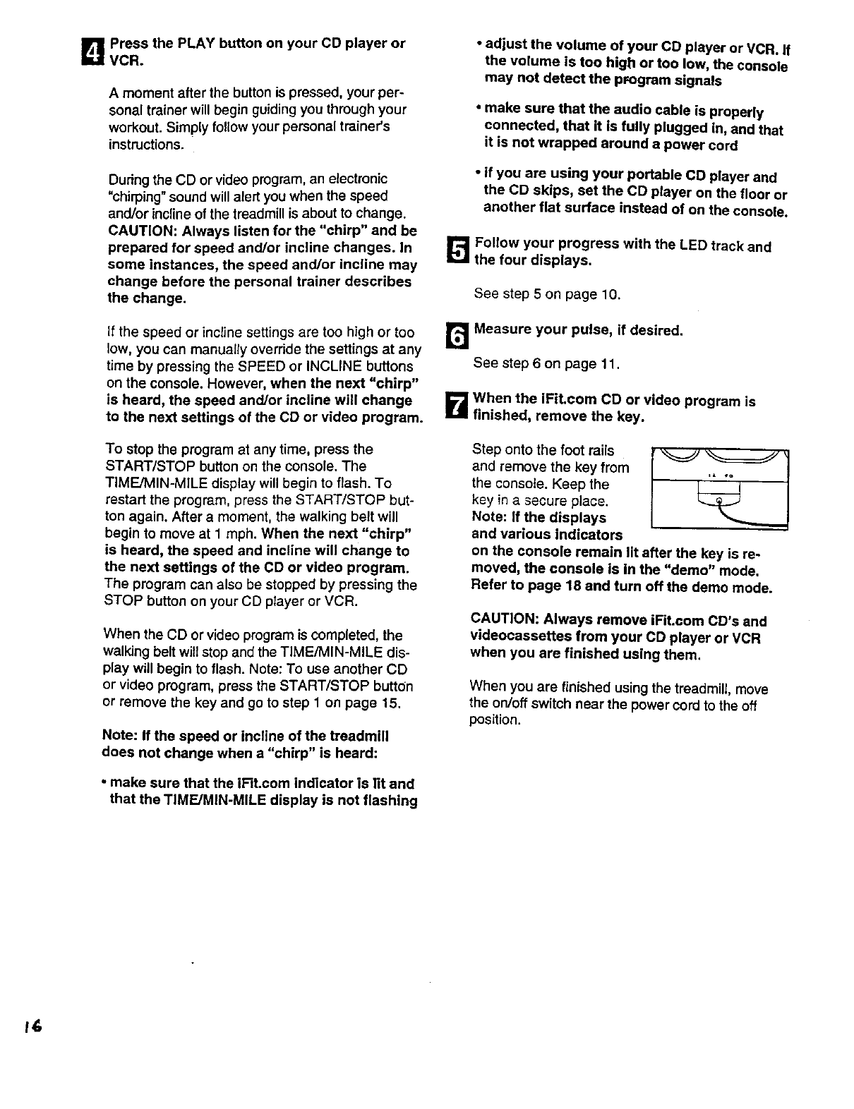
B When the iFit.com CD or video program is
finished, remove the key.
Step onto the foot rails
and remove the key from
the console. Keep the
key in a secure place.
Note: If the displays
and various indicators
on the console remain lit after the key is re-
moved, the console is in the "demo" mode.
Refer to page 18 and turn off the demo mode.
CAUTION: Always remove IFit.com CD's and
videocassettes from your CD player or VCR
when you are finished using them.
When you are finished using the treadmill, move
the on/off switch near the power cord to the off
position.
•
Our new intemet site at www.iFit.com allows you to
access a large selection of programs that interactively
control your treadmill to help you achieve your specific
exercise goals. In addition, you can play iFit.com audio
and video programs directly from the intemet. By
adding an optional upgrade module to the console, you
can use virtually endless features on our intemet site.
Explore www.iFit.com for details. To purchase an up-
grade module, call toll*free 1-800-735-0768.
To use programs from our internet site, the treadmill
must be connected to your home computer. See HOW
TO CONNECT YOUR COMPUTER on page 14. In ad-
dition, you must have at least a 56K modem and an
account with an internet service provider. A list of addi-
tional system and software requirements will be found
on our intemet site.
"aeuettI
on/off switch near the
power cord is in the on po- On
sition. In addition, make Position
sure that the power cord is
properly plugged in (see
HOW TO PLUG IN THE POWER CORD on page 8).
Follow the steps below to use a program from our
intemet site.
_1 Insert the key fully into the console.
When the key is
inserted, the four dis-
plays and various indi-
cators on the console
will light.
i& vQ
B
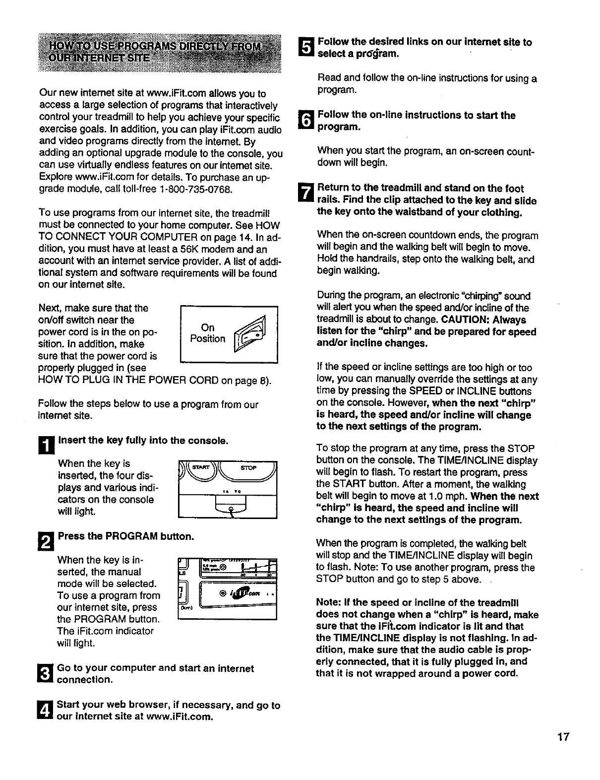
When the key is in-
serted, the manual
mode will be selected.
To use a program from
our internet site, press
the PROGRAM button.
The iFit.com indicator
will light.
Press the PROGRAM button.
_'_Go to your computer and start an internet
connection.
Follow the desired links on our intemet site to
select a prO'_ram.
Read and follow the on-line instructions for using a
program.
r_ Follow the on-line instructions to start the
program.
When you start the program, an on-screen count-
down will begin.
B Return to the treadmill and stand on the foot
rails. Find the clip attached to the key and slide
the key onto the waistband of your clothing.
When the on-screen countdown ends, the program
will begin and the walking belt will begin to move.
Hold the handrails, step onto the walking belt, and
begin walking.
During the program, an electronic =chirping" sound
will alert you when the speed and/or incline of the
treadmill is about to change. CAUTION: Always
listen for the "chirp" and be prepared for speed
and/or incline changes.
If the speed or incline settings are too high or too
low, you can manually override the settings at any
time by pressing the SPEED or INCLINE buttons
on the console. However, when the next "chirp"
is heard, the speed and/or incline will change
to the next settings of the program.
To stop the program at any time, press the STOP
button on the console. The TIME/INCLINE display
will begin to flash. To restart the program, press
the START button. After a moment, the walking
belt will begin to move at 1.0 mph. When the next
"chirp" is heard, the speed and incline will
change to the next settings of the program.
When the program is completed, the walking belt
will stop and the TIME/INCLINE display will begin
to flash. Note: To use another program, press the
STOP button and go to step 5 above.
Note: if the speed or incline of the treadmill
does not change when a "chirp" is heard, make
sure that the iFit.com indicator is lit and that
the TIME/INCLINE display is not flashing. In ad-
dition, make sure that the audio cable is prop-
erly connected, that it is fully plugged in, and
that it is not wrapped around a power cord.
B Start your web browser, if necessary, and go to
our internet site at www.iFit.com.
17
B Follow your progress with the LED track and
the four displays.
See step 5on page 10.
!_! Measure your pulse, if desired.
See step 6 on page 11.
_1_ When the program is finished, remove the
key.
Step onto the foot rails and remove the key from
the console. Keep the key in a secure place. Note:
If the displays and various indicators on the
console remain lit after the key is removed, the
console is in the "demo" mode. Refer to the in-
structions at the right and turn off the demo
mode.
When you are finished using the treadmill, move
the on/off switch near the power cord to the off
position.
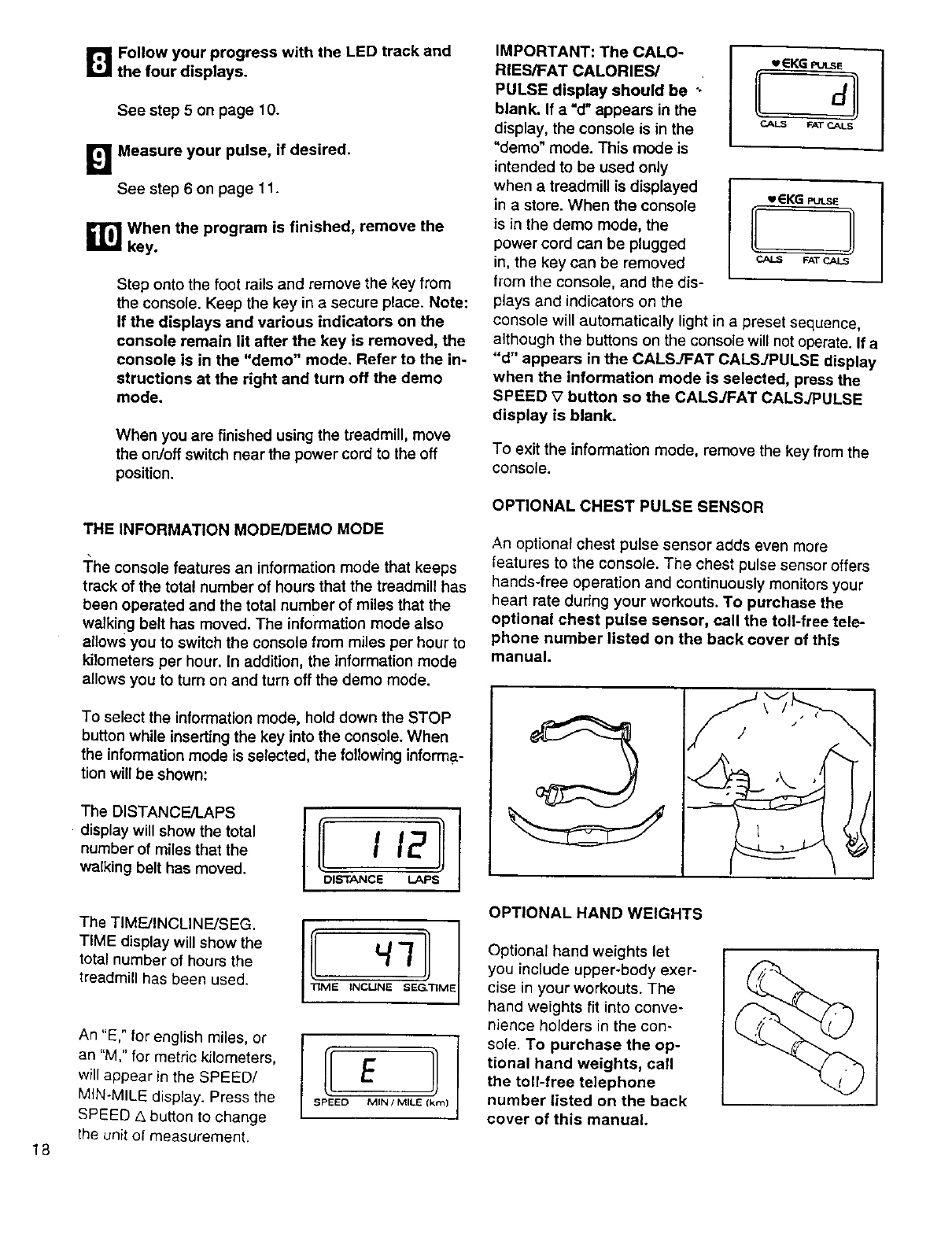
IMPORTANT: The CALO-
RIES/FAT CALORIES/
PULSE display should be ".
blank. If a "d" appears in the
display, the console is in the
"demo" mode. This mode is
intended to be used only
when a treadmill is displayed
in a store• When the console
is in the demo mode, the
power cord can be plugged
in, the key can be removed
from the console, and the dis-
plays and indicators on the
-EKG PULSE
EL4
CAI_ FAT _LN
-EKG PULSE
CALS FAT CALS
console will automatically light in a preset sequence,
although the buttons on the console will not operate• If a
"d" appears in the CALSJFAT CALSJPULSE display
when the information mode is selected, press the
SPEED _7button so the CALSJFAT CALSJPULSE
display is blank.
To exit the information mode, remove the key from the
console.
THE INFORMATION MODE/DEMO MODE
The console features an information mode that keeps
track of the total number of hours that the treadmill has
been operated and the total number of miles that the
walking belt has moved. The information mode also
allows you to switch the console from miles per hour to
kilometers per hour. In addition, the information mode
allows you to turn on and turn off the demo mode.
OPTIONAL CHEST PULSE SENSOR
An optional chest pulse sensor adds even more
features to the console. The chest pulse sensor offers
hands-free operation and continuously monitors your
heart rate during your workouts. To purchase the
optional chest pulse sensor, call the toll-free tele-
phone number listed on the back cover of this
manual.
18
To select the information mode, hold down the STOP
button while inserting the key into the console. When
the information mode is selected, the following informa-
tion will be shown:
•.eOST,NO PS
• display will show the total
number of miles that the
walking belt has moved. DISTANCE LAPS
The TIMFJINCLINFJSEG.
TIME display will show the
total number of hours the
treadmill has been used. ]3ME INCUNE 8EG,'nM 1
An "E," for english miles, or
an "M," for metric kilometers,
will appear in the SPEED/
MIN-MILE display• Press the
SPEED ,_ button to change
the unit of measurement.
IE
SPEED MIN /MILE (l<m} J
OPTIONAL HAND WEIGHTS
Optional hand weights let
you include upper-body exer-
cise in your workouts. The
hand weights fit into conve-
nience holders in the con-
sofe. To purchase the op-
tional hand weights, call
the toll-free telephone
number listed on the back
cover of this manual.
HOW TO FOLD AND MOVE THE TREADMILL
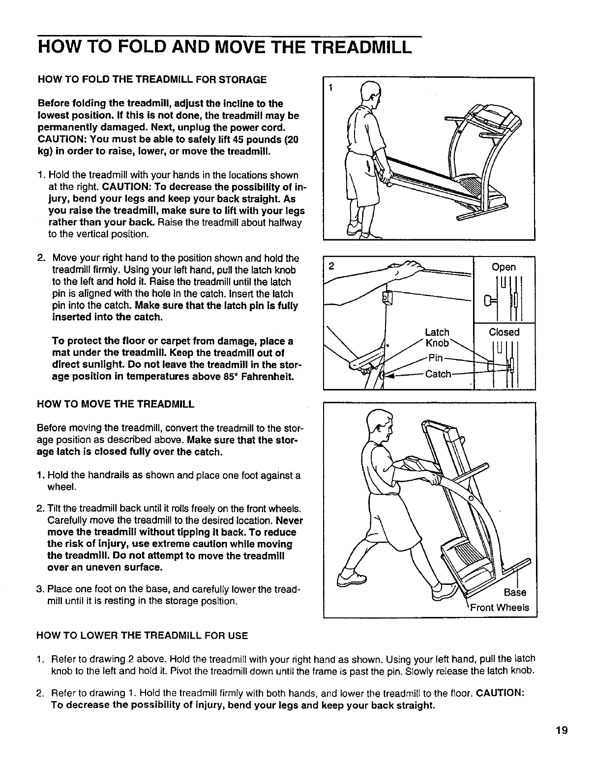
HOW TO FOLD THE TREADMILL FOR STORAGE
Before folding the treadmill, adjust the incline to the
lowest position. If this is not done, the treadmill may be
permanently damaged. Next, unplug the power cord.
CAUTION: You must be able to safely lift 45 pounds (20
kg) in order to raise, lower, or move the treadmill.
1. Hold the treadmill with your hands in the locations shown
at the right. CAUTION: To decrease the possibility of in-
jury, bend your legs and keep your back straight. As
you raise the treadmill, make sure to lift with your legs
rather than your back. Raise the treadmill about halfway
to the vertical position.
2. Move your dght hand to the position shown and hold the
treadmill firmly. Using your left hand, pull the latch knob
to the left and hold it. Raise the treadmill until the latch
pin is aligned with the hole in the catch. Insert the latch
pin into the catch. Make sure that the latch pin is fully
inserted into the catch.
To protect the floor or carpet from damage, place a
mat under the treadmill. Keep the treadmill out of
direct sunlight. Do not leave the treadmill in the stor-
age position in temperatures above 85° Fahrenheit.
Open
Closed
HOW TO MOVE THE TREADMILL
Before moving the treadmill, convert the treadmill to the stor-
age position as described above. Make sure that the stor-
age latch is closed fully over the catch.
1. Hold the handrails as shown and place one foot against a
wheel.
2. Tilt the treadmill back until it rollsfreely on the front wheels.
Carefully move the treadmill to the desired location. Never
move the treadmill without tipping it back. To reduce
the risk of injury, use extreme caution while moving
the treadmill. Do not attempt to move the treadmill
over an uneven surface.
3. Place one foot on the base, and carefully lower the tread-
mill until it is resting in the storage position. ase
:ront Wheels
HOW TO LOWER THE TREADMILL FOR USE
1. Refer to drawing 2 above. Hold the treadmill with your right hand as shown. Using your left hand, pull the latch
knob to the left and hold it. Pivot the treadmill down until the frame is past the pin. Slowly release the latch knob.
2. Refer to drawing 1. Hold the treadmill firmly with both hands, and lower the treadmill to the floor. CAUTION:
To decrease the possibility of injury, bend your legs and keep your back straight.
19
TROUBLE-SHOOTING
Most treadmill problems can be solved by following the simple steps below. Find the symptom that
applies, and follow the steps listed, if further assistance is needed, call our toll-free HELPMNE at
1-800-736-6879, Monday through Saturday, 7 a.m. until 7 p.m. Central Time (excluding holidays).
PROBLEM: The power does not turn on
SOLUTION: a. Make sure that the power cord is plugged into a surge suppressor, and that the surge suppressor
is plugged into a properly grounded outlet (see page 7). Use only asingle-outlet surge suppressor
that is UL 1449 listed as a transient voltage surge suppressor (TVSS). The surge suppressor
must have aUL suppressed voltage rating of 400 volts or less and a minimum surge dissipation
of 450 joules. The surge suppressor must be electrically rated for 120 volts AC and 15 amps.
b. After the power cord has been plugged in, rnake sure that the key is fully inserted into the con*
sole. See step 1 on page 10.
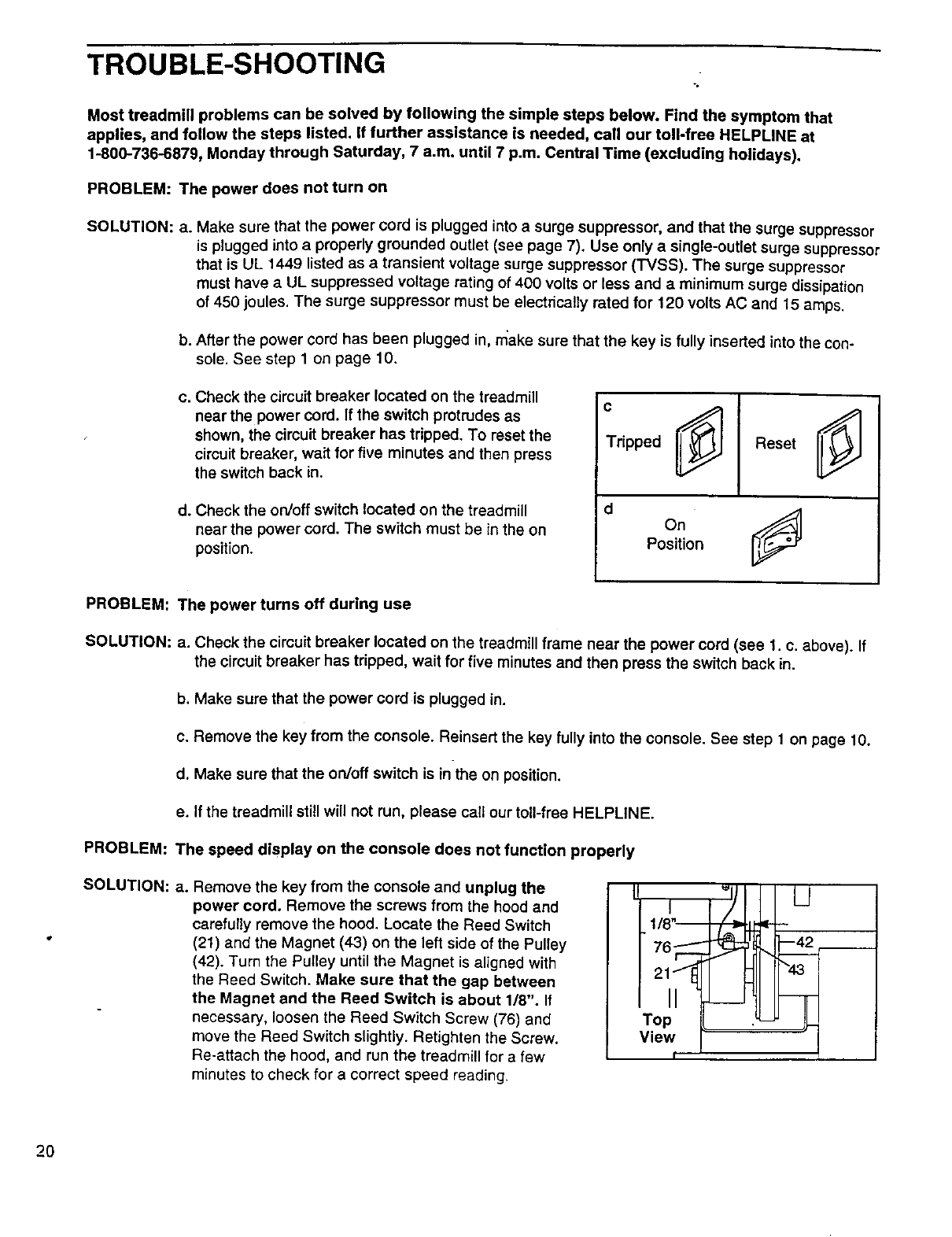
C.
d°
Check the circuit breaker located on the treadmill
near the power cord. if the switch protrudes as
shown, the circuit breaker has tripped. To reset the
circuit breaker, wait for five minutes and then press
the switch back in.
Check the on/off switch located on the treadmill
near the power cord. The switch must be in the on
position.
C
Tripped Reset
onj
Position
PROBLEM: The power turns off during use
SOLUTION: a. Check the circuit breaker located on the treadmill frame near the power cord (see 1. c. above). If
the circuit breaker has tripped, wait for five minutes and then press the switch back in.
b. Make sure that the power cord is plugged in.
c. Remove the key from the console. Reinsert the key fully into the console. See step 1on page 10.
d. Make sure that the on/off switch is in the on position.
e. If the treadmill still will not run, please call our toll-free HELPLINE.
PROBLEM: The speed display on the console does not function properly
SOLUTION: a. Remove the key from the console and unplug the
power cord. Remove the screws from the hood and
carefully remove the hood. Locate the Reed Switch
(21) and the Magnet (43) on the left side of the Pulley
(42). Turn the Pulley until the Magnet is aligned with
the Reed Switch. Make sure that the gap between
the Magnet and the Reed Switch is about 1/8". If
necessary, loosen the Reed Switch Screw (76) and
move the Reed Switch slightly. Retighten the Screw.
Re-attach the hood, and run the treadmill for a few
minutes to check for a correct speed reading.
' U
Top _
View !
2O
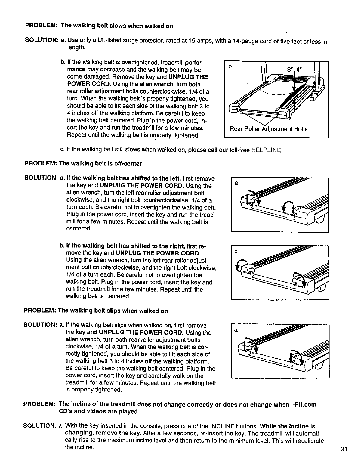
PROBLEM: The walking belt slows when walked on
SOLUTION: a. Use only a UL-listed surge protector, rated at 15 amps, with a 14-gauge cord of five feet or less in
length.
b. If the walking belt is overtightened, treadmill perfor-
mance may decrease and the walking belt may be-
come damaged. Remove the key and UNPLUG THE
POWER CORD. Using the allen wrench, turn both
rear roller adjustment bolts counterclockwise, 114of a
turn. When the walking belt is propedy tightened, you
should be able to lifteach side ofthe walking belt 3 to
4inches off the walking platform. Be careful to keep
the walking belt centered. Plug in the power cord, in-
sert the key and run the treadmillfor afew minutes.
Repeat until the walking belt is propedy tightened.
b
Rear Roller Adjustment Bolts
c. If the walking belt still slows when walked on, please call our toll-free HELPLINE.
PROBLEM: The walking belt is off-center
SOLUTION: a. If the walking belt has shifted to the left, first remove
the key and UNPLUG THE POWER CORD. Using the
allen wrench, turn the left rear miler adjustment bolt
clockwise, and the right bolt counterclockwise, 1/4 of a
turn each. Be careful not to overtighten the walking belt.
Plug in the power cord, insert the key and run the tread-
mill for a few minutes. Repeat untilthe walking belt is
centered.
a
b. If the walking belt has shifted to the right, first re-
move the key and UNPLUG THE POWER CORD.
Using the allen wrench, turn the left rear roller adjust-
ment bolt counterclockwise, and the dght bolt clockwise,
1/4 of a turn each. Be careful not to overtighten the
walking belt. Plug in the power cord, insert the key and
run the treadmill for a few minutes. Repeat until the
walking belt is centered.
PROBLEM: The walking belt slips when walked on
SOLUTION: a. If the walking belt slips when walked on, first remove
the key and UNPLUG THE POWER CORD. Using the
allen wrench, turn both rear roller adjustment bolts
clockwise, 1/4 of a turn. When the walking belt is cor-
rectly tightened, you should be able to lift each side of
the walking belt 3 to 4 inches off the walking platform.
Be careful to keep the walking belt centered. Plug in the
power cord, insert the key and carefully walk on the
treadmill for afew minutes. Repeat until the walking belt
is prepedy tfghtened.
PROBLEM: The incline of the treadmill does not change correctly or does not change when i-Fit.com
CD's and videos are played
SOLUTION: a. With the key inserted in the console, press one of the INCLINE buttons. While the incline is
changing, remove the key. After afew seconds, re-insert the key. The treadmill will automatf-
cally rise to the maximum incline level and then return to the minimum level. This will recalibrate
the incline. 21
CONDITIONING GUIDELINES
'30
I_ I • w
I. Before beginning this:.
ram; yOUl; pl_ys_! _;:_
tant for_individu _
with pr_
problems.
Lota medical device.
Vadqus factors, including your movement,
mayi:aff_tthe accuracy of heart rate readings.:•
•,Thb se_s0i is intended only as an exercise aid
:=:it_dete_inin_i:_art rate trends in general.
The following guidelines will help you to pian your ex-
ercise program. Remember--these are general guide-
lines only. For more detailed exercise information, ob-
tain a reputable _ook or consult your physician.
EXERCISE INTENSITY
Whether your goal is to bum fat or to strengthen your
cardiovascular system, the key to achieving the
desired results is to exercise with the proper intensity.
The proper intensibj !evel can be found by using your
heart rate as a guide. The cha_ below shows recom-
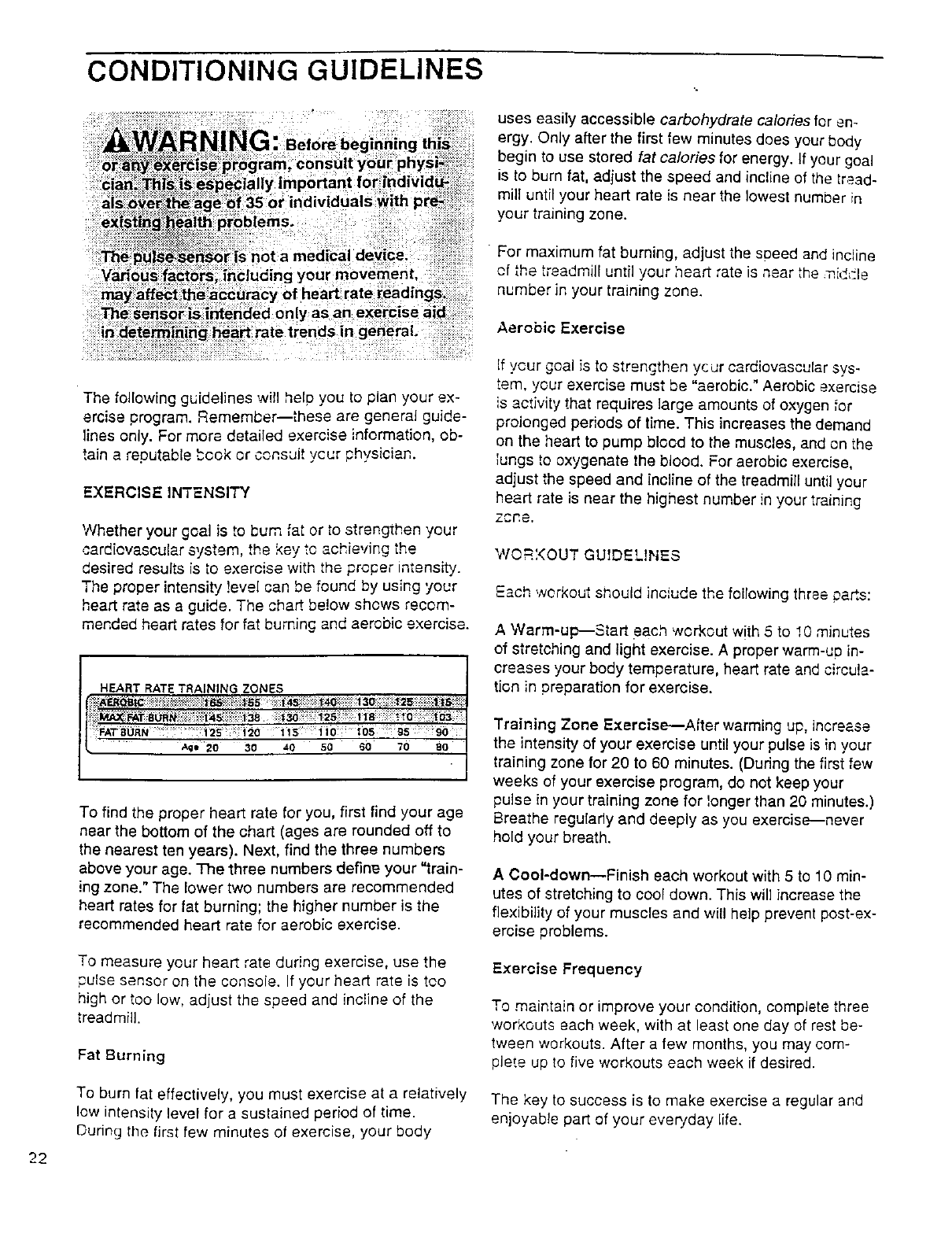
mended heart rates for fat burning and aerobic exercise.
HEART RATE TRAINING ZONES
Age 20 30 40 50 60 70
To find the proper heart rate for you, first find your age
near the bottom of the chart (ages are rounded off to
the nearest ten years). Next, find the three numbers
above your age. The three numbers define your "train-
ing zone." The lower two numbers are recommended
heart rates for fat burning; the higher number is the
recommended heart rate for aerobic exercise.
To measure your heart rate during exercise, use the
pulse sensor on the console. If your heart rate is too
high or too low, adjust the speed and incline of the
treadmill.
Fat Burning
To burn fat effectively, you must exercise at a relatively
low intensity level for a sustained period of time.
During the first few minutes of exercise, your body
uses easily accessible carbohydrate calories for en-
ergy. Only after the first few minutes does your body
begin to use stored fat calories for energy. If your goal
is to burn fat, adjust the speed and incline of the tread-
mill until your heart rate is near the lowest number in
your training zone.
For maximum fat burning adjust the sueed and incline
of the treadmill until your heart rate is near the middle
number in your training zone.
Aerobic Exercise
If ycur goal is to strengthen your cardiovascular sys-
tem, your exercise must be "aerobic." Aerobic exercise
is activity that requires large amounts of oxygen for
prolonged periods of time. This increases the demand
on the heart to pump blood to the muscles, and on the
lungs to oxygenate the blood. For aerobic exercise,
adjust the speed and incline of the treadmill until your
heart rate is near the highest number in your training
zone.
WOR?(OUT GUIDELIHES
Each workout should inc!ude the following three parts:
AWarm-up--Start each workout with 5 to I0 minutes
of stretching and light exercise. Aproper warm-up in-
creases your body temperature, heart rate and circula-
tion in preparation for exercise.
Training Zone E×ercise---After warming up, increase
the intensity of your exercise until your pulse is in your
training zone for 20 to 60 minutes. (During the first few
weeks of your exercise program, do not keep your
pulse in your training zone for longer than 20 minutes.)
Breathe regularly and deeply as you exercise---never
hold your breath.
ACool-down--Finish each workout with 5 to 10 min-
utes of stretching to cool down. This will increase the
flexibility of your muscles and will help prevent post-ex-
ercise problems.
Exercise Frequency
To maintain or improve your condition, complete three
workouts each week, with at least one day of rest be-
tween workouts. After a few months, you may com-
plete up to five workouts each week if desired.
The key to success is to make exercise a regular and
enjoyable part of your everyday life.
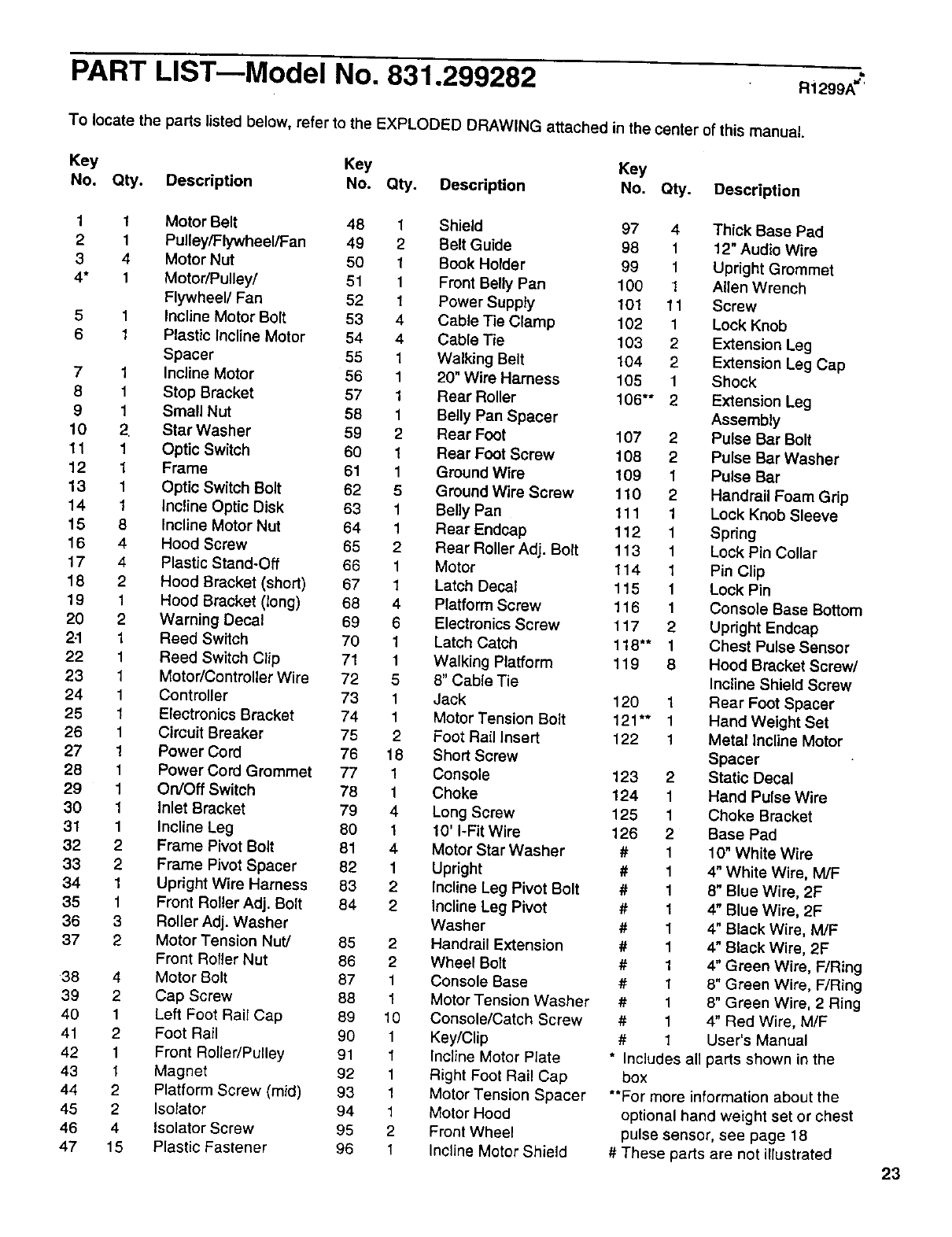
PART LIST--Model No. 831.299282 Ri299A"
To locate the parts listed below, refer to the EXPLODED DRAWING attached in the center of this manual.
Key Key Key
No. Qty. Description No. Qty. Description No. Qty. Description
1 1 Motor Belt 48 1Shield 97 4 Thick Base Pad
2 1 Pulley/Flywheel/Fan 49 2 Belt Guide 98 1 12" Audio Wire
3 4 Motor Nut 50 1 Book Holder 99 1 Upright Grommet
4* 1 Motor/Pulley/ 61 1 Front Belly Pan 100 1 Allen Wrench
Flywheel/Fan 52 1 Power Supply 101 11 Screw
5 1 Incline Motor Bolt 53 4 Cable Tie Clamp 102 1 Lock Knob
6 1 Plastic Incline Motor 54 4 Cable Tie 103 2 Extension Leg
Spacer 55 1 Walking Belt 104 2 Extension Leg Cap
7 1 Incline Motor 56 1 20" Wire Harness 105 1 Shock
8 1 Stop Bracket 57 1 Rear Roller 106"* 2 Extension Leg
9 1 Small Nut 58 1 Belly Pan Spacer Assembly
10 2. Star Washer 59 2 Rear Foot 107 2 Pulse Bar Bolt
11 1 Optic Switch 60 1 Rear Foot Screw 108 2 Pulse Bar Washer
12 1Frame 61 1 Ground Wire 109 1 Pulse Bar
13 1 Optic Switch Bolt 62 5Ground Wire Screw 110 2 Handrail Foam Grip
14 1 Incline Optic Disk 63 1 Belly Pan 111 1 Lock Knob Sleeve
15 8 Incline Motor Nut 64 1 Rear Endcap 112 1 Spring
16 4 Hood Screw 65 2 Rear Roller Adj. Bolt 113 1 Lock Pin Collar
17 4 Plastic Stand-Off 66 1 Motor 114 1 Pin Clip
1B2 Hood Bracket (short) 67 1Latch Decal 115 1 Lock Pin
19 1 Hood Bracket (long) 68 4 Platform Screw 116 1 Console Base Bottom
20 2 Warning Decal 69 6 Electronics Screw 117 2 Upright Endcap
2-1 1 Reed Switch 70 1 Latch Catch 118"* 1 Chest Pulse Sensor
22 1 Reed Switch Clip 71 1 Walking Platform 119 8Hood Bracket Screw/
23 1 Motor/Controller Wire 72 5 8" Cable Tie Incline Shield Screw
24 1 Controller 73 1 Jack 120 1 Rear Foot Spacer
25 1 Electronics Bracket 74 1 Motor Tension Bolt 121"* 1 Hand Weight Set
26 1 Circuit Breaker 75 2 Foot Rail Insert 122 1 Metal Incline Motor
27 1 Power Cord 76 18 Short Screw Spacer
28 1 Power Cord Grommet 77 1 Console 123 2 Static Decal
29 1 On/Off Switch 78 1 Choke 124 1 Hand Pulse Wire
30 1 Inlet Bracket 79 4 Long Screw 125 1 Choke Bracket
31 1 Incline Leg 80 1 10' I-Fit Wire 126 2 Base Pad
32 2 Frame Pivot Bolt 81 4 Motor Star Washer # 1 10" White Wire
33 2 Frame Pivot Spacer 82 1 Upright # 1 4" White Wire, M/F
34 1 Upright Wire Harness 83 2 Incline Leg Pivot Bolt # 1 8" Blue Wire, 2F
35 1Front Roller Adj. Bolt 84 2 Incline Leg Pivot # 1 4" Blue Wire, 2F
36 3Roller Adj. Washer Washer # 1 4" Black Wire, M/F
37 2 Motor Tension Nut/ 85 2 Handrail Extension # 1 4" Black Wire, 2F
Front Roller Nut 86 2 Wheel Bolt # 1 4" Green Wire, FIRing
38 4 Motor Bolt 87 1 Console Base # 1 8" Green Wire, F/Ring
39 2 Cap Screw 88 1 Motor Tension Washer # 1 8" Green Wire, 2 Ring
40 1Left Foot Rail Cap 89 10 Console/Catch Screw # 1 4" Red Wire, M/F
41 2 Foot Rail 90 1 Key/Clip # 1 User's Manual
42 1 Front RolledPulley 91 1Incline Motor Plate * Includes all parts shown in the
43 1 Magnet 92 1 Right Foot Rail Cap box
44 2 Platform Screw (re{d) 93 1 Motor Tension Spacer **For more information about the
45 2 Isolator 94 1 Motor Hood optional hand weight set or chest
46 4 Isolator Screw 95 2 Front Wheel pulse sensor, see page 18
47 15 Plastic Fastener 96 1 Incline Motor Shield # These parts are not illustrated 23
75
45
70
71
41 33
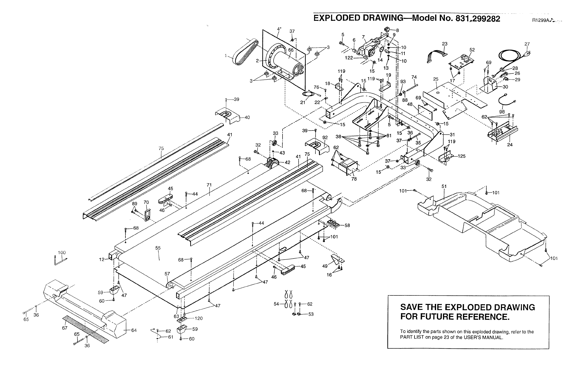
EXPLODED DRAWING--Model No. 831.299282
37
74
69
23
25
51
119
-i'Ll01
R1299A__.---
_36
65
100
67
65
36
6O
i
47
55
68_
57
6_ 120
46
SAVE THE EXPLODED DRAWING
FOR FUTURE REFERENCE.
To identifythe parts shown on this exploded drawing, refer to the
PART LIST on page 23 of the USER'S MANUAL.
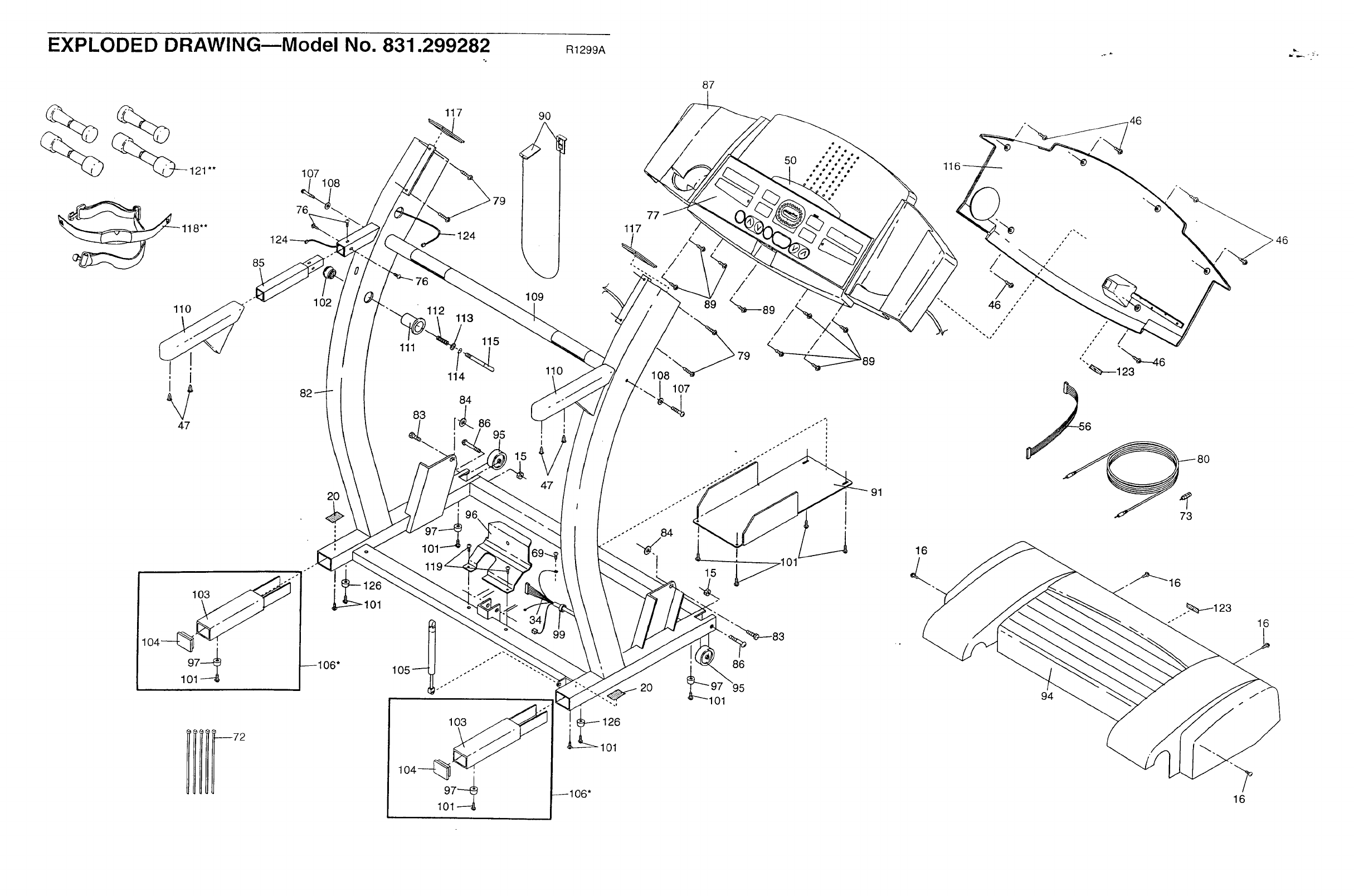
EXPLODED DRAWINGmModel No. 831.299282 R1299A
118"*
85
107
<
76
108
117
110
i i
\
47
102
114
109
90
110
87
/
11
46
46
--72
20
!
g
i
_106"
01
1
11
105_.........-'""'"
103
101
47
20
101
I
101
86
i
91
16
94
73
16
16

SEARS
Model No. 831.299282
QUESTIONS?
If you find that:
•you need help assembling or
operating the PROFORM
830QT treadmill
• a part is missing
• or you need to schedule repair
service
call our toll-free HELPLINE
1-800-736-6879
Monday-Saturday, 7 am-7 pm
Central Time (excluding holidays)
REPLACEMENT
PARTS
If parts become worn and need
to be replaced, call the following
toll-free number
1-800-FON-PART
(1-800-366-7278)
The model number and sedal number of your PROFORM • 830QT
treadmill are listed on a decal attached to the frame. See the front
cover of this manual to find the location of the decal
All replacement parts are available for immediate purchase or
special order when you visit your nearest SEARS Service Center.
To request §ervice or to order parts by telephone, call the toll-free
numbers listed at the left.
When requesting help or service, or ordering parts, please be
prepared to provide the following information:
• The NAME OF THE PRODUCT (PROFORM" 830QT treadmill)
•The MODEL NUMBER OF THE PRODUCT (831.299282)
• The KEY NUMBER AND DESCRIPTION OF THE PART (see the
EXPLODED DRAWING in the center of this manual and the
PART LIST on page 23).
1FULL 90 DAY WARRANTY
For 90 days from the date of purchase, if failure occurs due to defect in material or workmanship in this
SEARS TREADMILL EXERCISER, contact the nearest SEARS Service Center throughout the United
States and SEARS will repair or replace the TREADMILL EXERCISER, free of charge.
This warranty does not apply when the TREADMILL EXERCISER is used commercially or for rental pur-
poses.
This warranty gives you specific legal rights, and you may also have other rights which vary fromstate
to state.
SEARS, ROEBUCK AND CO., DEPT. 817WA, HOFFMAN ESTATES, IL 60179
Part No. 161763 R1299A Printed in USA © 1999 Sears, Roebuck and Co.
