Proform DRC39940 User Manual CROSSTRAINER 55/56 Manuals And Guides L0503422
PROFORM Cycle Manual L0503422 PROFORM Cycle Owner's Manual, PROFORM Cycle installation guides
User Manual: Proform DRC39940 DRC39940 PROFORM PROFORM CROSSTRAINER 55/56 - Manuals and Guides View the owners manual for your PROFORM PROFORM CROSSTRAINER 55/56 #DRC39940. Home:Fitness Equipment Parts:Proform Parts:Proform PROFORM CROSSTRAINER 55/56 Manual
Open the PDF directly: View PDF ![]() .
.
Page Count: 24
Model No. PFEX39930
Seriat No.
Serial Number Decal
QUESTIONS?
if you have questions, or if
there are missing pars, we witl
guarantee complete satisfac-
tion through direct assistance
from our factory.
TO AVOID DELAYS, PLEASE
CALL DIRECT TO OUR TOLL-
FREE CUSTOMER HOT LINE.
The trained technicians on our
customer hot line will provide
immediate assistance, free of
charge to you.
CUSTOMER HOT LINE:
1°800°999°3756
Mon.=Fri., 6a.m.=6 p.m. MST
CAUTION
Read all precautions and instruc-
tions in this manual before using
this equipment. Keep this manuaJ
for future reference.
www.proform.com
new products, prizes,
fitness tips, and much more!
TABLE OF CONTENTS
iMPORTANT PRECAUTIONS ............................................................. 2
BEFORE YOU BEGIN ................................................................... 3
ASSEMBLY ........................................................................... 4
HOW TO USE THE RECUMBENT CYCLE .................................................... 8
RECUMBENT CYCLE EXERCISE GUIDELINES .............................................. 18
WEIGHT BENCH EXERCISE GUIDELINES .................................................. 19
MAINTENANCE AND TROUBLESHOOTING ................................................. 21
PART LIST ........................................................................... 22
EXPLODED DRAWING ................................................................. 23
HOW TO ORDER REPLACEMENT PARTS ........................................... Back Cover
LIMITED WARRANTY ........................................................... Back Cover
IMPORTANT PRECAUTIONS
;'_ WARN RNG: Toreducethe.skofae.ous_njury,readthefo.owingimportantprecau-
tionsbefore using the crosstrainer.
1. Read all instructions in this manual before
using the ctosstrainer,
that could become caught on the crosatrain-
er. Always wear shoes for foot protection.
2. it is the responsibility of the owner to ensure 9. Before using the weight bench, always
that all users of the crosstra iner are ade=
quately informed of aH precautions,
3. The crosstrainer is intended for home use
only. Do not use the crosstrainer in a com-
mercial rental or institutional setting.
4. Place the croastrainer on a level surface.
with a mat beneath it to protect the floor or
carpet. Keep the crosstrainer indoors, away
from moisture and dust.
adjust the seat to the farthest fot_vard posi-
tion. Never sit on the backrest or the head-
rest; doing so couJd cause the crosatrainer
to tip, resuJting in injury.
10. Keep your back straight when using the
crosstrainer: do not arch your back.
11. The croastrainer includes three pairs of
hand weights. Do not use other weights with
the crosstrainer.
5. Inspect and property tighten aH parts regu-
larly. Replace any worn parts immediately.
12. When you stop pedaling, allow the pedals to
slowly come to a stop.
6. Keep children under age 12 and pets away
from the crosatrainer at al_ times.
7. The crosstrainet should not be used by per-
sons weighing more than 250 pounds.
13. The pulse sensor is not a medical device.
Various factors may affect the accuracy of
heart rate readings. The pulse sensor is
intended only as an exercise aid in determm=
ing heart rate trends in general
8. Wear appropriate exercise clothing when
using the crosstrainer; do not wear cJothing
14. Jfyou feel pain or dizziness while e×ercising,
stop immediately and begin cooling down.
,_ WARN JNG: Beforebeginningth_soranye×erciseprogram,consultyourphya_c_an.
This is especially important for persons over the age of 35 or persons with pre-existing health prob-
meres. Read aH instructions before using° _CON assumes no responsibility for personal injury or
property damage sustained by or through the use of this product.
2
BEFORE YOU BEGIN
Congratulations for selecting the new PROFORM '_
CROSSTRAINER 55. The unique PROFORM _'
CROSSTRAINER 55 combines a comfortable recum-
bent cycle with a convenient weight bench to let you
enjoy both aerobic exercise and strength training
exercise in the convenience of your home.
For your benefit, read this manual carefully before
you use the crosstrainer. If you have questions after
reading this manual, please call our Customer Service
Department toll=free at 1=800=999=3756, Monday
through Friday, 6 a.m. until 6 p.m. Mountain Time
(excluding holidays). To help us assist you, please
note the product model number and serial number
before calling. The model number is PFEX39930. The
serial number can be found on a decal attached to the
crosstrainer (see the front cover of this manual for the
location of the decal).
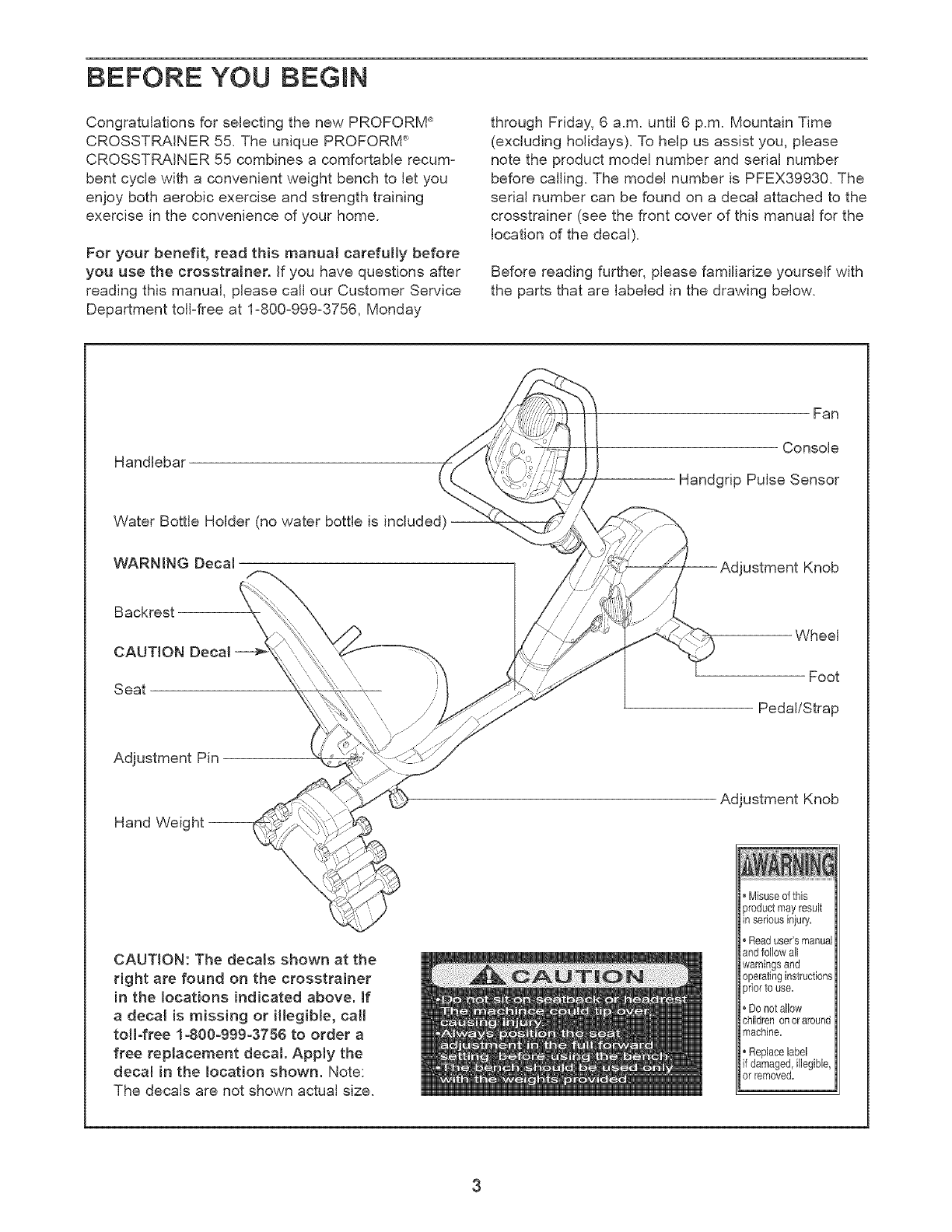
Before reading further, please familiarize yourself with
the parts that are labeled in the drawing below.
Handlebar
Water Bottle Holder (no water bottle is included}
WARMNG Deca{
Fan
Console
Handgrip Pulse Sensor
Knob
Backrest
CAUTION Decal \
i
Seat r
"a //
Wheel
Foot
Pedal/Strap
Adjustment Pin
Hand Weight-
Adjustment Knob
CAUTION: The decals shown at the
right are found on the crosstrainer
in the locations indicated above. If
a decal is missing or illegible, call
toll-free 1-800-999-3786 to order a
free replacement decal. Apply the
decal in the Location shown. Note:
The decals are not shown actual size.
* Misuseof this
productmayresult
inseriousinjury.
, Readuser'srnanual
andfollowall
warningsand
operatinginstructions
priorto use.
,Donot allow
childrenonoraround
machine.
• Replacelabel
if damaged,illegible,
orremoved.
ASSEMBLY
Assembly requires two persons. Place all parts of the crosstrainer in a cleared area and remove the packing
materials. Do not dispose of the packing materials until assembly is completed. In addition to the included
atien wrenches, assembly requires a phitlips screwdriver _-_, an adjustable wrench
and a rubber mallet ...........
L _ ic::c1 )•
i,
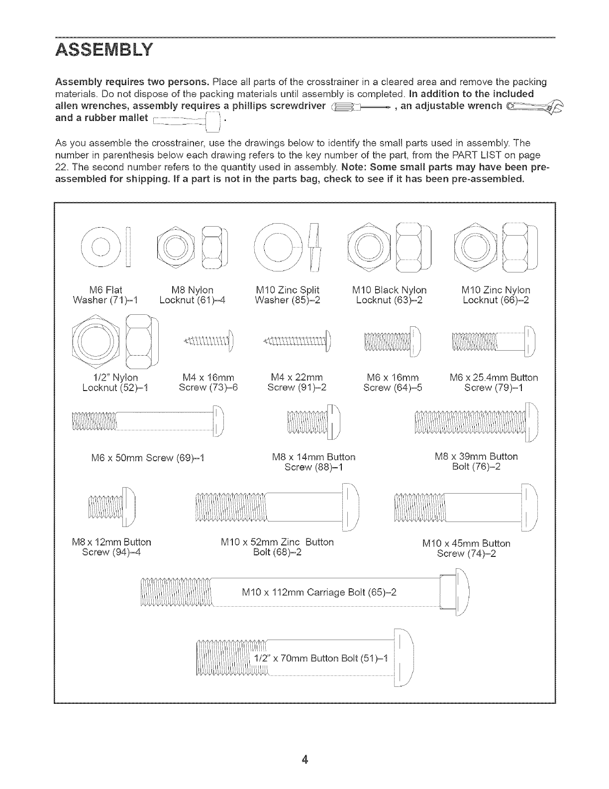
As you assemble the crosstrainer, use the drawings below to identify the small parts used in assembly. The
number in parenthesis below each drawing refers to the key number of the part, from the PART LiST on page
22. The second number refers to the quantity used in assembly. Note: Some small parts may have been pre°
assembled for shipping. If a part is not in the parts bag, check to see if it has been pre-assembled.
M6 Flat M8 Nylon MI0 Zinc Split MI0 Black Nylon M10 Zinc Nylon
Washer (71)-1 Locknut (61)--4 Washer (85)-2 Locknut (63)-2 Locknut (66)=2
1/2" Nylon M4 x 16mm M4 x 22mm M6 x 16mm M6 x 25.4mm Button
Locknut (52)-1 Screw (73)-6 Screw (91)=2 Screw (64)-5 Screw (79)-1
M6 x 50mm Screw (69)-1 M8 x 14mm Button
Screw (88)=1
i1\
i
M8 x 39mm Button
Bolt (76)-2
M8 x 12mm Button
Screw (94)-4 M10 x 52mm Zinc Button
Bolt (68)=2 M10 x 45mm Button
Screw (74)-2
M10 x 112mm Carriage Bolt (65)-2
1/2" x 70mm Button Bolt (51)-1 i
LJ
4
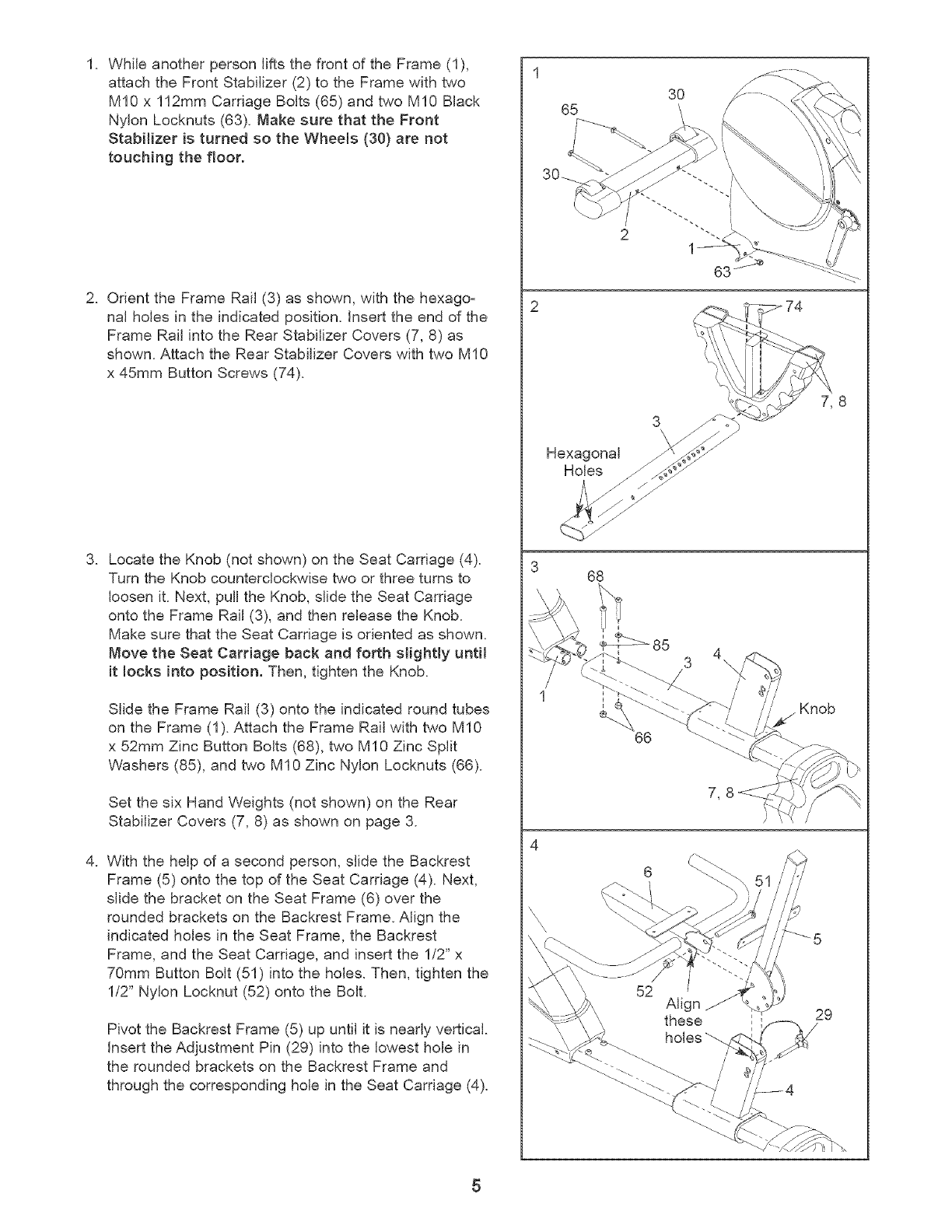
1. While another person lifts the front of the Frame (1),
attach the Front Stabilizer (2) to the Frame with two
MI0 x 112mm Carriage Bolts (65) and two MI0 Black
Nylon Locknuts (63). Make sure that the Front
Stabilizer is turned so the Wheels (30) are not
touching the floor.
2. Orient the Frame Rail (3) as shown, with the hexago z
nal holes in the indicated position, insert the end of the
Frame Rail into the Rear Stabilizer Covers (7, 8) as
shown. Attach the Rear Stabilizer Covers with two M10
x 45ram Button Screws (74).
3. Locate the Knob (not shown) on the Seat Carriage (4).
Turn the Knob counterclockwise two or three turns to
loosen it. Next, pull the Knob, slide the Seat Carriage
onto the Frame Rail (3), and then release the Knob.
Make sure that the Seat Carriage is oriented as shown.
Move the Seat Carriage back and forth slightly until
it locks into position. Then, tighten the Knob.
Slide the Frame Rail (3) onto the indicated round tubes
on the Frame (1). Attach the Frame Rail with two MI0
x 52mm Zinc Button Bolts (68), two MI 0 Zinc Split
Washers (85), and two M10 Zinc Nylon Locknuts (66).
Set the six Hand Weights (not shown) on the Rear
Stabilizer Covers (7, 8) as shown on page 3.
4. With the help of a second person, slide the Backrest
Frame (5) onto the top of the Seat Carriage (4). Next,
slide the bracket on the Seat Frame (6) over the
rounded brackets on the Backrest Frame. Align the
indicated holes in the Seat Frame, the Backrest
Frame, and the Seat Carriage, and insert the 1/2" x
70mm Button Bolt (51) into the holes. Then, tighten the
1/2" Nylon Locknut (52) onto the Bolt.
Pivot the Backrest Frame (5) up until it is nearly vertical.
Insert the Adjustment Pin (29) into the lowest hole in
the rounded brackets on the Backrest Frame and
through the corresponding hole in the Seat Carriage (4).
65 3O
I
2
63
Hexagonal
Holes
368
3 4\
/
66
Align
these
holes
Knob
29
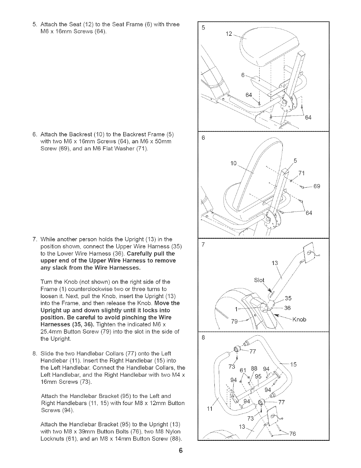
5. AttachtheSeat(12)to theSeatFrame(6)withthree
M6x 16mmScrews(64).
6. AttachtheBackrest(10)totheBackrestFrame(5)
withtwoM6x 16mmScrews(64),anM6x 50mm
Screw(69),andanM6FlatWasher(71).
7. WhileanotherpersonholdstheUpright(13)inthe
positionshown,connecttheUpperWireHarness(35)
to theLowerWireHarness(36).Carefullypull the
upperend of the Upper Wire Harness to remove
any slack from the Wire Harnesses.
Turn the Knob (not shown) on the right side of the
Frame (1) counterclockwise two or three turns to
loosen it. Next, puJJthe Knob, insert the Upright (13)
into the Frame, and then release the Knob. Move the
Upright up and down stightly unt/ it locks into
posit{on. Be careful to avoid p{nching the Wire
Harnesses (35, 36). Tighten the indicated M6 x
25Amm Button Screw (79) into the slot in the side of
the Upright.
8. Slide the two Handlebar Collars (77) onto the Left
Handlebar (11). insert the Right Handlebar (15)into
the Left Handlebar. Connect the Handlebar Collars, the
Left Handlebar, and the Right Handlebar with two M4 x
16mm Screws (73).
Attach the Handlebar Bracket (95) to the Left and
Right Handlebars (11, 15) with four M8 x 12mm Button
Screws (94).
Attach the Handlebar Bracket (95) to the Upright (13)
with two M8 x 39mm Button Bolts (76), two M8 Nylon
Locknuts (61), and an M8 x 14ram Button Screw (88).
6
10 5
/
71
64
Slot\
13
36
73 61
11
13
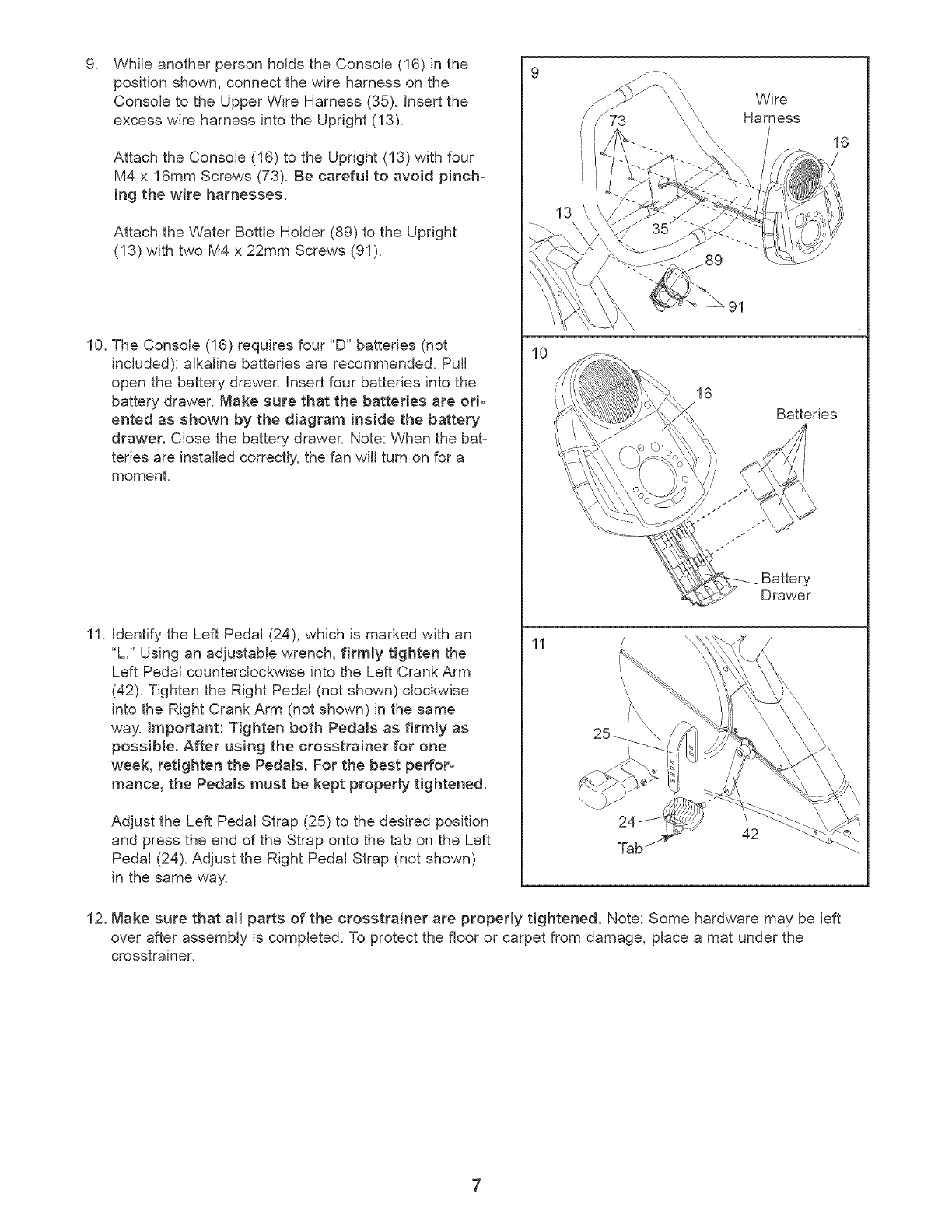
WhileanotherpersonholdstheConsole(16)inthe
positionshown,connectthewireharnessonthe
Consoleto theUpperWireHarness(35).Insertthe
excesswireharnessintotheUpright(13).
AttachtheConsole(16)totheUpright(13)withfour
M4x 16mmScrews(73).Becarefulto avoidpinch-
ing thewire harnesses.
AttachtheWaterBottleHolder(89)to theUpright
(13)withtwoM4x 22mmScrews(91).
10.TheConsole(16)requiresfour"D"batteries(not
included);alkalinebatteriesarerecommended.Pull
openthebatterydrawer.Insertfourbatteriesintothe
batterydrawer.Makesurethatthe batteriesareori-
entedasshownby thediagraminsidethebattery
drawer.Closethebatterydrawer.Note:Whenthebat-
teriesareinstalledcorrectly,thefanwillturnonfora
moment.
11.IdentifytheLeftPedal(24),whichis markedwithan
"L" Usinganadjustablewrench,firmlytightenthe
LeftPedalcounterclockwiseintotheLeftCrankArm
(42).TightentheRightPedal(notshown)clockwise
intotheRightCrankArm(notshown)inthesame
way.Important:TightenbothPedalsasfirmlyas
possible.Afterusingthe crosstrainerfor one
week,retightenthePedals.Forthebestperfor-
mance,thePedalsmustbekeptproperlytightened.
AdjusttheLeftPedalStrap(25)to thedesiredposition
andpresstheendof theStrapontothetabontheLeft
Pedal(24).AdjusttheRightPedalStrap(notshown)
inthesameway.
13
10
11
Wire
Harness
91
16
Batteries
Battery
Drawer
42
16
12. Make sure that aH parts of the crosstrainer are properly tightened. Note: Some hardware may be left
over after assembly is completed. To protect the floor or carpet from damage, place a mat under the
crosstrainer.
HOW TO USE THE RECUMBENT CYCLE
The crosstrainer features a recumbent cycle for aerobic exercise, and a convenient weight bench for strength
training exercise. To use the recumbent cycle, see pages 8 to 18. To use the weight bench, see page 19.
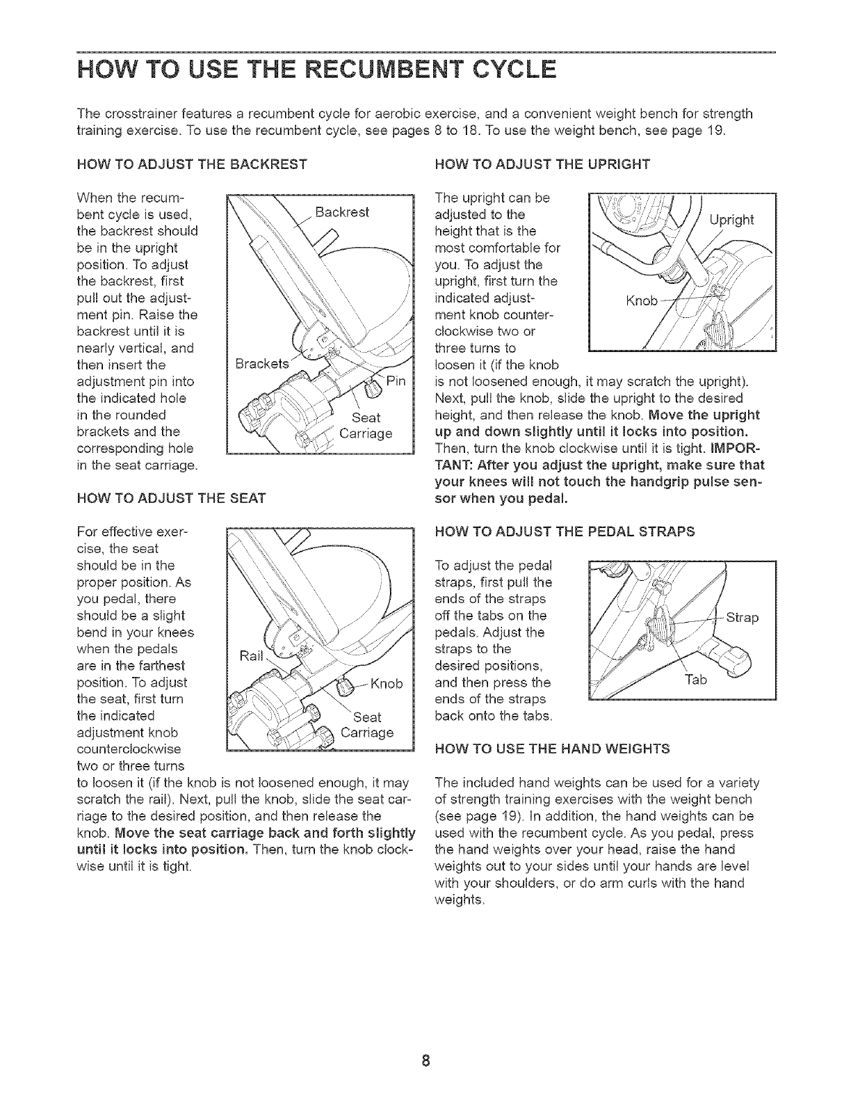
HOW TO ADJUST THE BACKREST HOW TO ADJUST THE UPRIGHT
When the recum-
bent cycle is used,
the backrest should
be in the upright
position. To adjust
the backrest, first
pull out the adjust-
ment pin. Raise the
backrest until it is
neady vertical, and
then insert the
adjustment pin into
the indicated hole
in the rounded
brackets and the
corresponding hole
in the seat carriage.
HOW TO ADJUST THE SEAT
Backrest
Seat
Carriage
The upright can be
adjusted to the Upright
height that is the
most comfortable for
you. To adjust the
upright, first turn the
indicated adjust- Knob
ment knob counter-
clockwise two or
three turns to
loosen it (if the knob
is not loosened enough, it may scratch the upright).
Next, pull the knob, slide the upright to the desired
height, and then release the knob. Move the upright
up and down slightly until it locks into position.
Then, turn the knob clockwise until it is tight. IMPOR-
TAN'[.' After you adjust the upright, make sure that
your knees will not touch the handgrip pulse sen-
sor when you pedal.
For effective exer-
cise, the seat
should be in the
proper position. As
you pedal, there
should be a slight
bend in your knees
when the pedals
are in the farthest
position. To adjust
the seat, first turn
the indicated
adjustment knob Carriage
counterclockwise
two or three turns
to loosen it (if the knob is not loosened enough, it may
scratch the rail). Next, pull the knob, slide the seat car-
riage to the desired position, and then release the
knob. Move the seat carriage back and forth slightly
until it locks into posit{on. Then, turn the knob clock-
wise until it is tight.
HOW TO ADJUST THE PEDAL STRAPS
To adjust the pedal
straps, first pull the
ends of the straps
off the tabs on the
pedals. Adjust the
straps to the
desired positions,
and then press the
ends of the straps
back onto the tabs.
Tab
Strap
HOW TO USE THE HAND WEIGHTS
The included hand weights can be used for a variety
of strength training exercises with the weight bench
(see page 19). In addition, the hand weights can be
used with the recumbent cycle. As you pedal, press
the hand weights over your head, raise the hand
weights out to your sides until your hands are level
with your shoulders, or do arm curls with the hand
weights.
DisplayButtons
Button
f .........................................
_ Stoat±Programs
i, -,_ v _ i VVeightLoss Interval 1 3 Aerobic Progressfve
WeightLoss Plateau 4 Aerobic Interval
5 Performanoe Progressive
6 PeCrormanoe Interval
On/Reset Button
Resistance Buttons
\
!I
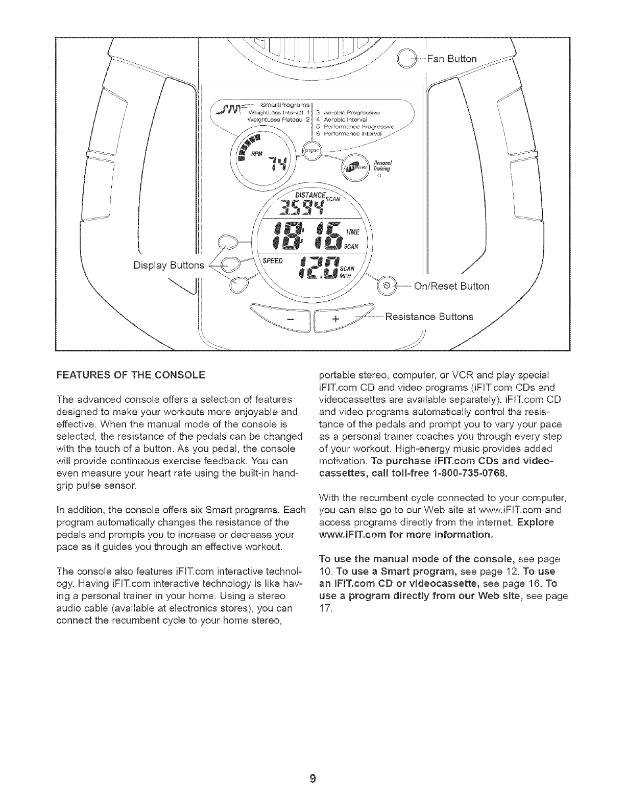
FEATURES OF THE CONSOLE
The advanced console offers a selection of features
designed to make your workouts more enjoyable and
effective. When the manual mode of the console is
selected, the resistance of the pedals can be changed
with the touch of a button. As you pedal, the console
will provide continuous exercise feedback. You can
even measure your heart rate using the built-in hand-
grip pulse sensor.
in addition, the console offers six Smart programs. Each
program automatically changes the resistance of the
pedals and prompts you to increase or decrease your
pace as it guides you through an effective workout.
The console also features iFF.com interactive technol-
ogy. Having iFF.com interactive technology is like hav-
ing a personal trainer in your home. Using a stereo
audio cable (available at electronics stores), you can
connect the recumbent cycle to your home stereo,
portable stereo, computer, or VCR and play special
iFIT.com CD and video programs (iFIT.com CDs and
videocassettes are available separately), iFF.com CD
and video programs automatically control the resis-
tance of the pedals and prompt you to vary your pace
as a personal trainer coaches you through every step
of your workout. High-energy music provides added
motivation. To purchase iFIT.com CDs and video-
cassettes, call toll-free 1-800-735-0768.
With the recumbent cycle connected to your computer,
you can also go to our Web site at www.iFIT.com and
access programs directly from the internet. Explore
www.iFIT.com for more information.
To use the manual mode of the console, see page
10. To use a Smart program, see page 12. To use
an iFIT.com CD or videocassette, see page 16. To
use a program directly from our Web site, see page
17.
HOWTOUSETHEMANUALMODE
TurnontheconsoJe.
Note:Theconsolerequiresfour1.5V"D"batteries
(seeassemblystep10onpage7).
Toturnontheconsole,presstheOn/Resetbutton
orbeginpedaling.(Seethedrawingonpage9to
identifytheOn/Resetbutton.)
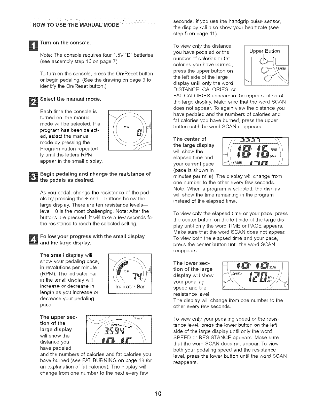
Selectthemanualmode.
Eachtimetheconsoleis
turnedon,themanual
modewillbeselected,if a
programhasbeenselect-
ed,selectthemanual
modebypressingthe
Programbuttonrepeated-
lyuntilthelettersRPM
appearinthesmalldisplay.
Beginpedalingandchangethe resistanceof
the pedalsasdesired.
Asyoupedal,changetheresistanceoftheped=
aisbypressingthe+and- buttonsbelowthe
largedisplay.Therearetenresistancelevels--
level10isthemostchallenging.Note:Afterthe
buttonsarepressed,it willtakeafewsecondsfor
theresistancetoreachtheselectedsetting.
FoJtowyour progresswiththesmalldisplay
andthelarge display.
The small display wHJ
show your pedaling pace,
in revolutions per minute
(RPM). The indicator bar
in the small display will
increase or decrease in
length as you increase or
decrease your pedaling
pace.
indicator Bar
The upper sec-
tion of the
large display
wiJJshow the
distance you
have pedaled
and the numbers of calories and fat ca[odes you
have burned (see FAT BURNING on page 18 for
an explanation of fat calories). The display will
change from one number to the next every few
seconds, if you use the handgrip pulse sensor,
the display will also show your heart rate (see
step 5 on page 11).
To view only the distance
you have pedaled or the
number of calories or fat
calories you have burned,
press the upper button on
the left side of the large
display until only the word
DISTANCE, CALORIES, or
Upper Button
FAT CALORIES appears in the upper section of
the large display. Make sure that the word SCAN
does not appear. To again view the distance you
have pedaled and the numbers of calories and
fat calories you have burned, press the upper
button until the word SCAN reappears.
The center of
the _arge display
will show the
elapsed time and
your current pace
(pace is shown in
minutes per mile). The display will change from
one number to the other every few seconds.
Note: When a program is selected, the display
will show the time remaining in the program
instead of the elapsed time.
To view only the elapsed time or your pace, press
the center button on the left side of the large dis-
play until only the word TIME or PACE appears.
Make sure that the word SCAN does not appear.
To view both the elapsed time and your pace,
press the center button until the word SCAN
reappears.
The lower sec-
tion of the marge
display will show
your pedaling
speed and the
resistance level.
The display will change from one number to the
other every few seconds.
To view only your pedaling speed or the resis-
tance level, press the lower button on the left
side of the large display until only the word
SPEED or RESISTANCE appears. Make sure
that the word SCAN does not appear. To view
both your pedaling speed and the resistance
level, press the lower button until the word SCAN
reappears.
10
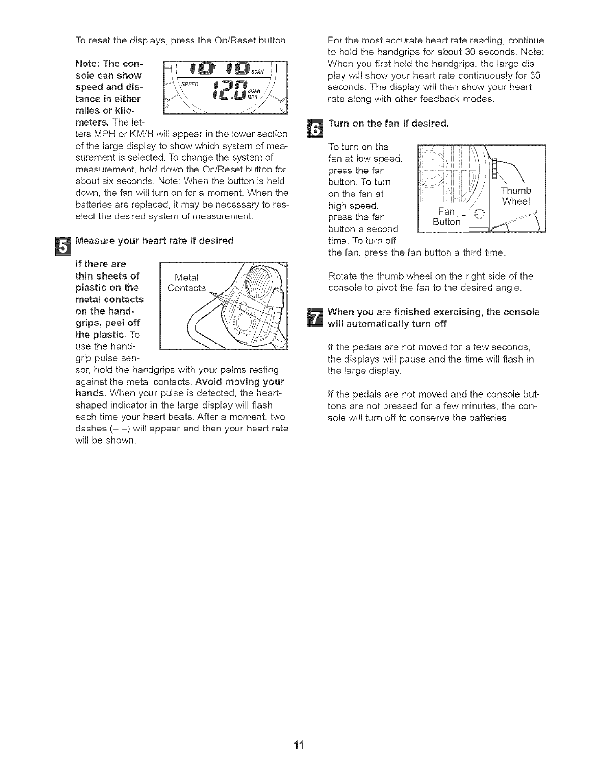
To reset the displays, press the On/Reset button.
Note: The con=
sole can show
speed and dis= Q
tance in either
miles or kilo=
meters. The let=
ters MPH or KM/H will appear in the lower section
of the large display to show which system of mea=
surement is selected. To change the system of
measurement, hold down the On/Reset button for
about six seconds. Note: When the button is held
down, the fan will turn on for a moment. When the
batteries are replaced, it may be necessary to res=
elect the desired system of measurement.
Measure your heart rate if desired.
if there are
thin sheets of Metal
plastic on the Contacts
metam contacts
on the hand=
grips, peel off
the plastic. To
use the hand-
grip pulse sen-
sor, hold the handgrips with your palms resting
against the metal contacts. Avoid moving your
hands. When your pulse is detected, the heart-
shaped indicator in the large display will flash
each time your heart beats. After a moment, two
dashes (= =) will appear and then your heart rate
will be shown.
For the most accurate heart rate reading, continue
to hold the handgdps for about 30 seconds. Note:
When you first hold the handgrips, the large dis-
play will show your heart rate continuously for 30
seconds. The display will then show your heart
rate along with other feedback modes.
Turn on the fan if desired.
To turn on the
fan at low speed,
press the fan
button. To turn
on the fan at
high speed,
press the fan Button
button a second
time. To turn off
the fan, press the fan button a third time.
Thumb
Wheel
Rotate the thumb wheel on the right side of the
console to pivot the fan to the desired angle.
When you are finished exercising, the console
witl automatically turn off.
If the pedals are not moved for a few seconds,
the displays wiJJpause and the time will flash in
the large display.
If the pedals are not moved and the console but=
tons are not pressed for a few minutes, the con=
sole will turn off to conserve the batteries.
11
HOW TO USE A SMART PROGRAM
Each Smart program will automatically change the
resistance of the pedals and prompt you to increase or
decrease your pace as it guides you through an effec-
tive workout. Programs 1 and 2 are weight Joss pro-
grams, programs 3 and 4 are aerobic programs, and
programs 5 and 6 are high-performance programs.
Follow the steps below to use a Smart program.
Turn on the console.
See step 1 on page 10.
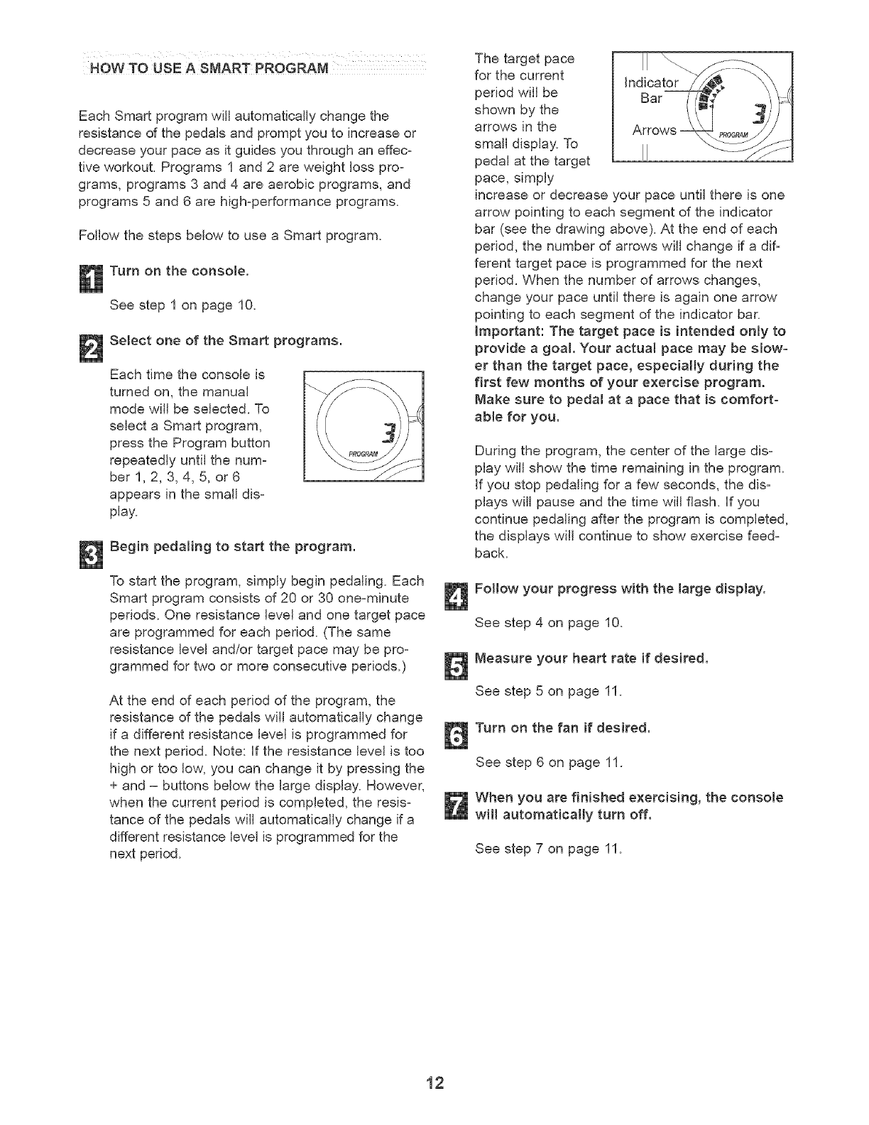
Select one of the Smart programs.
Each time the console is
turned on, the manual
mode will be selected. To
select a Smart program,
press the Program button
repeatedly until the num=
ber 1, 2, 3, 4, 5, or 6
appears in the small dis=
play.
Begin pedaling to start the program.
To start the program, simply begin pedaling. Each
Smart program consists of 20 or 30 one-minute
periods. One resistance level and one target pace
are programmed for each period. (The same
resistance level and/or target pace may be pro-
grammed for two or more consecutive periods.)
At the end of each period of the program, the
resistance of the pedals will automatically change
if a different resistance level is programmed for
the next period. Note: if the resistance level is too
high or too low, you can change it by pressing the
+ and = buttons below the large display. However,
when the current period is completed, the resis-
tance of the pedals will automatically change if a
different resistance level is programmed for the
next period.
The target pace
for the current
period will be
shown by the
arrows in the
small display. To
pedal at the target
pace, simply
increase or decrease your pace until there is one
arrow pointing to each segment of the indicator
bar (see the drawing above). At the end of each
period, the number of arrows will change if a dif=
ferent target pace is programmed for the next
period. When the number of arrows changes,
change your pace until there is again one arrow
pointing to each segment of the indicator bar.
important: The target pace is intended only to
provide a goa!. Your actual pace may be slow-
er than the target pace, especially during the
first few months of your exercise program.
Make sure to pedal at a pace that is comfort-
able for you.
During the program, the center of the large dis=
play will show the time remaining in the program.
If you stop pedaling for a few seconds, the dis=
plays will pause and the time will flash. If you
continue pedaling after the program is completed,
the displays will continue to show exercise feed-
back.
Follow your progress with the large display.
See step 4 on page 10.
Measure your heart rate if desired.
See step 5 on page 11.
Turn on the fan if desired.
See step 6 on page 11.
When you are finished exercising, the console
witl automatically turn off.
See step 7 on page 11.
12
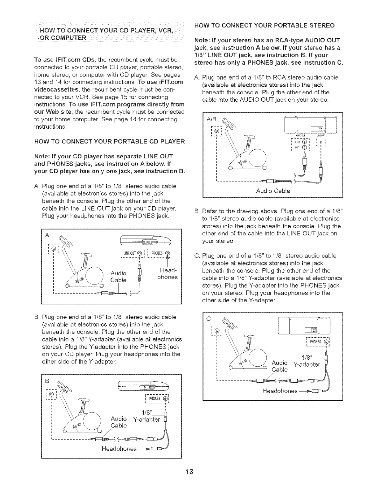
NOWTO CONNECT YOUR CD PLAYER, VCR_
OR COMPUTER
To use iFIT.com CDs, the recumbent cycle must be
connected to your portable CD player, portable stereo,
home stereo, or computer with CD player. See pages
13 and 14 for connecting instructions. To use iF_T.com
videocassettes, the recumbent cycle must be con-
nected to your VCR. See page 15 for connecting
instructions. To use iFIT.com programs directly from
out Web site, the recumbent cycle must be connected
to your home computer. See page 14 for connecting
instructions.
HOW TO CONNECT YOUR PORTABLE CD PLAYER
Note: _fyour CD player has separate LiNE OUT
and PHONES jacks, see instruction A below, if
your CD player has only one jack, see instruction B.
A. Plug one end of a 1/8" to 1/8" stereo audio cable
(available at electronics stores) into the jack
beneath the console. Plug the other end of the
cable into the LiNE OUT jack on your CD player.
Plug your headphones into the PHONES jack.
Audio [_ Head-
_j phones
B. Plug one end of a 1/8" to 1/8" stereo audio cable
(available at electronics stores) into the jack
beneath the console. Plug the other end of the
cable into a 1/8" Y-adapter (available at electronics
stores). Plug the Y-adapter into the PHONES jack
on your CD player. Plug your headphones into the
other side of the Y-adapter.
HOW TO CONNECT YOUR PORTABLE STEREO
Note: If your stereo has an RCA-type AUDIO OUT
jack, see instruction A be!ow. If your stereo has a
1/8" UNE OUT jack, see instruction B. if your
stereo has only a PHONES jack, see instruction C.
A. Plug one end of a 1/8" to RCA stereo audio cable
(available at electronics stores) into the jack
beneath the console. Plug the other end of the
cable into the AUDIO OUT jack on your stereo.
AU_O0_ LINEC_T
u _ u L-a-,
u L_T _ u u
Audio Cable
B.
C.
Refer to the drawing above. Plug one end of a 1/8"
to 1/8" stereo audio cable (available at electronics
stores) into the jack beneath the console. Plug the
other end of the cable into the LINE OUT jack on
your stereo.
Plug one end of a 1/8" to 1/8" stereo audio cable
(available at electronics stores) into the jack
beneath the console. Plug the other end of the
cable into a 1/8" Y-adapter (available at electronics
stores). Plug the Y-adapter into the PHONES jack
on your stereo. Plug your headphones into the
other side of the Y-adapter.
C
13
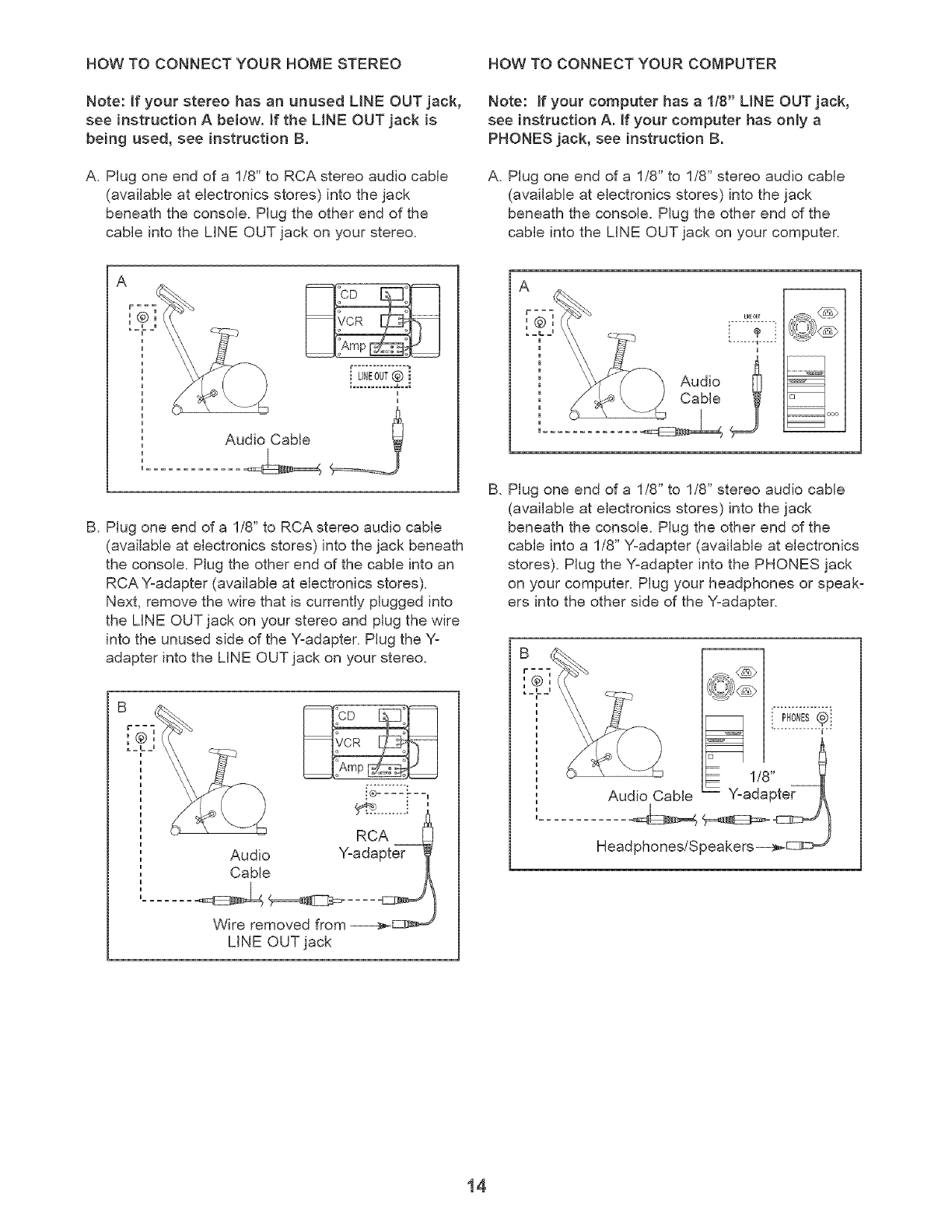
HOW TO CONNECT YOUR HOME STEREO HOW TO CONNECT YOUR COMPUTER
Note: if your stereo has an unused LiNE OUT jack,
see instruction A below. Jf the LiNE OUT jack is
being used, see instruction B.
A. Plug one end of a 1/8" to RCA stereo audio cable
(available at electronics stores) into the jack
beneath the console. Plug the other end of the
cable into the LiNE OUT jack on your stereo.
Note: if your computer has a 1/8" LINE OUT jack,
see instruction A. If your computer has only a
PHONES jack, see instruction B.
A. Plug one end of a 1/8" to 1/8" stereo audio cable
(available at electronics stores) into the jack
beneath the console. Plug the other end of the
cable into the LiNE OUT jack on your computer.
B. Plug one end of a 1/8" to RCA stereo audio cable
(available at electronics stores) into the jack beneath
the console. Plug the other end of the cable into an
RCA Y-adapter (available at electronics stores).
Next, remove the wire that is currently plugged into
the LiNE OUT jack on your stereo and plug the wire
into the unused side of the Y-adapter. Plug the Y-
adapter into the LiNE OUT jack on your stereo.
Audio
Cable
i®.... -__
RCA
Y-adapter
Wire removed from _c_,=_
LiNE OUT jack
L_0U_
Audio
B. Plug one end of a 1/8" to 1/8" stereo audio cable
(available at electronics stores) into the jack
beneath the console. Plug the other end of the
cable into a 1/8" Y-adapter (available at electronics
stores). Plug the Y-adapter into the PHONES jack
on your computer. Plug your headphones or speak-
ers into the other side of the Y-adapter.
Audio Cable
LP!o E!.. I
1/8"
Y:adapter
Head phones/Speakers-i_c:3z_ ,
14
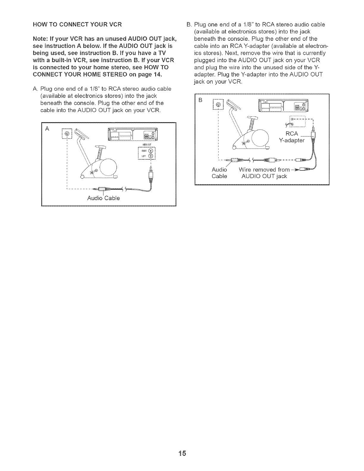
HOW TO CONNECT YOUR VCR
Note: ifyour VCR has an unused AUDIO OUT jack,
see instructionA below. JftheAUDIO OUT jack is
being used, see instruction B. Jf you have a TV
with abuiltdnVCR, see instructionB. if your VCR
isconnected to your home stereo,see HOW TO
CONNECT YOUR HOME STEREO on page 14.
A. Plug one end of a 1/8" to RCA stereo audio cable
(available at electronics stores) into the jack
beneath the console. Plug the other end of the
cable into the AUDIO OUT jack on your VCR.
A..2.i
0=.L"D22fi=..
.....@ i
....@i
Audio Cable
B. Plug one end of a 1/8" to RCA stereo audio cable
(available at electronics stores) into the jack
beneath the console. Plug the other end of the
cable into an RCA Y=adapter (available at electron=
ics stores). Next, remove the wire that is currently
plugged into the AUDIO OUT jack on your VCR
and plug the wire into the unused side of the Y=
adapter. Plug the Y=adapter into the AUDIO OUT
jack on your VCR.
B .......
...... =,
Cable AUDIO OUT jack
15
HOW TO USE IFIT.COM CD AND VIDEO
PROGRAMS
To use iFF.com CDs or videocassettes, the recum=
bent cycle must be connected to your portable CD
player, portable stereo, home stereo, computer with
CD player, or VCR. See HOW TO CONNECT YOUR
CD PLAYER, VCR, OR COMPUTER on page 13. To
purchase iFIT.com CDs and videocassettes, call
toil-free 1-800-735-0768.
Follow the steps below to use an iFF.com CD or
video program.
Turn on the console.
See step 1 on page 10.
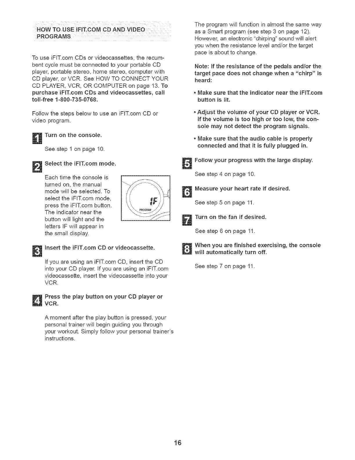
Select the iF_T.com mode.
Each time the console is
turned on, the manual
mode will be selected. To
select the iFIT.com mode,
press the iFF.com button.
The indicator near the
button will light and the
letters iF will appear in
the small display.
Insert the iF_T.com CD or videocassette.
if you are using an iFIT.com CD, insert the CD
into your CD player, if you are using an iFIT.com
videocassette, insert the videocassette into your
VCR.
Press the play button on your CD player or
VCR.
A moment after the play button is pressed, your
personal trainer will begin guiding you through
your workout. Simply follow your personal trainer's
instructions.
The program will function in almost the same way
as a Smart program (see step 3 on page 12).
However, an electronic "chirping" sound will alert
you when the resistance level and/or the target
pace is about to change.
Note: If the resistance of the pedals and/or the
target pace does not change when a "chirp" is
heard:
Make sure that the indicator near the iFiT.com
button is lit.
, Adjust the volume of your CD player or VCR.
If the volume is too high or too low, the con-
sole may not detect the program signams.
, Make sure that the audio cable is properly
connected and that it is fulty plugged in.
Follow your progress with the large display.
See step 4 on page 10.
Measure your heart rate if desired.
See step 5 on page 11.
Turn on the fan if desired.
See step 6 on page 11.
When you are finished exercising, the console
witl automatically turn off.
See step 7 on page 11.
16
HOW TO USE PROGRAMS DIRECTLY FROM
OUR WEB SiTE
Our Web site at www.iFF.com allows you to play
iFIT.com programs directly from the internet. To use
programs from our Web site, the recumbent cycle
must be connected to your computer. See HOW TO
CONNECT YOUR COMPUTER on page 14. In addi-
tion, you must have an internet connection and an
internet service provider. A list of specific system
requirements will be found on our Web site.
Follow the steps below to use a program from our
Web site.
Turn on the console.
See step 1 on page 10.
Select the iF_T.com mode.
Each time the console is
turned on, the manual
mode will be selected. To
select the iFF.com mode,
press the iFF.com button.
The indicator near the
button will light and the
letters IF will appear in
the small display.
Go to your computer and start an internet
connection.
Start your Web browser, if necessary, and go
to our Web site at v_,_Jv.iF_T.com.
Follow the desired links on our Web site to
select a program.
Follow the on-line instructions to start the
program.
When you start the program, an on=screen count-
down will begin.
Return to the recumbent cycle and begin
pedaling.
When the on=screen countdown ends, the pro=
gram will begin. The program will function in
almost the same way as a Smart program (see
step 3 on page 12). However, an electronic "chirp-
ing" sound will alert you when the resistance level
and/or the target pace is about to change.
Follow your progress with the large dispJay.
See step 4 on page 10.
Measure your heart rate if desired.
See step 5 on page 11.
When you are finished exercising, the console
witl automatically turn off.
See step 7 on page 11.
17
RECUMBENT CYCLE EXERCISE GUIDELINES
kWARNING:
Before beginning this or any exercise pro-
gram, consult your physician. This is espe-
cially important for persons over the age of 35
or persons with 9re=existing health problems.
The pulse sensor is not a medical device.
Various factors may affect the accuracy of
heart rate readings. The pulse sensor is
intended only as an exercise aid in determin-
ing heart rate trends in general.
The following guidelines will help you to plan your
workouts using the recumbent cycle. Remember that
proper nutrition and adequate rest are essential for
successful results.
EXERCISE iNTENSiTY
Whether your goal is to burn fat or to strengthen your
cardiovascular system, the key to achieving the
desired results is to exercise with the proper intensity.
The proper intensity level can be found by using your
heart rate as a guide. The chart below shows recom=
mended heart rates for fat burning, maximum fat
burning, and cardiovascular (aerobic) exercise.
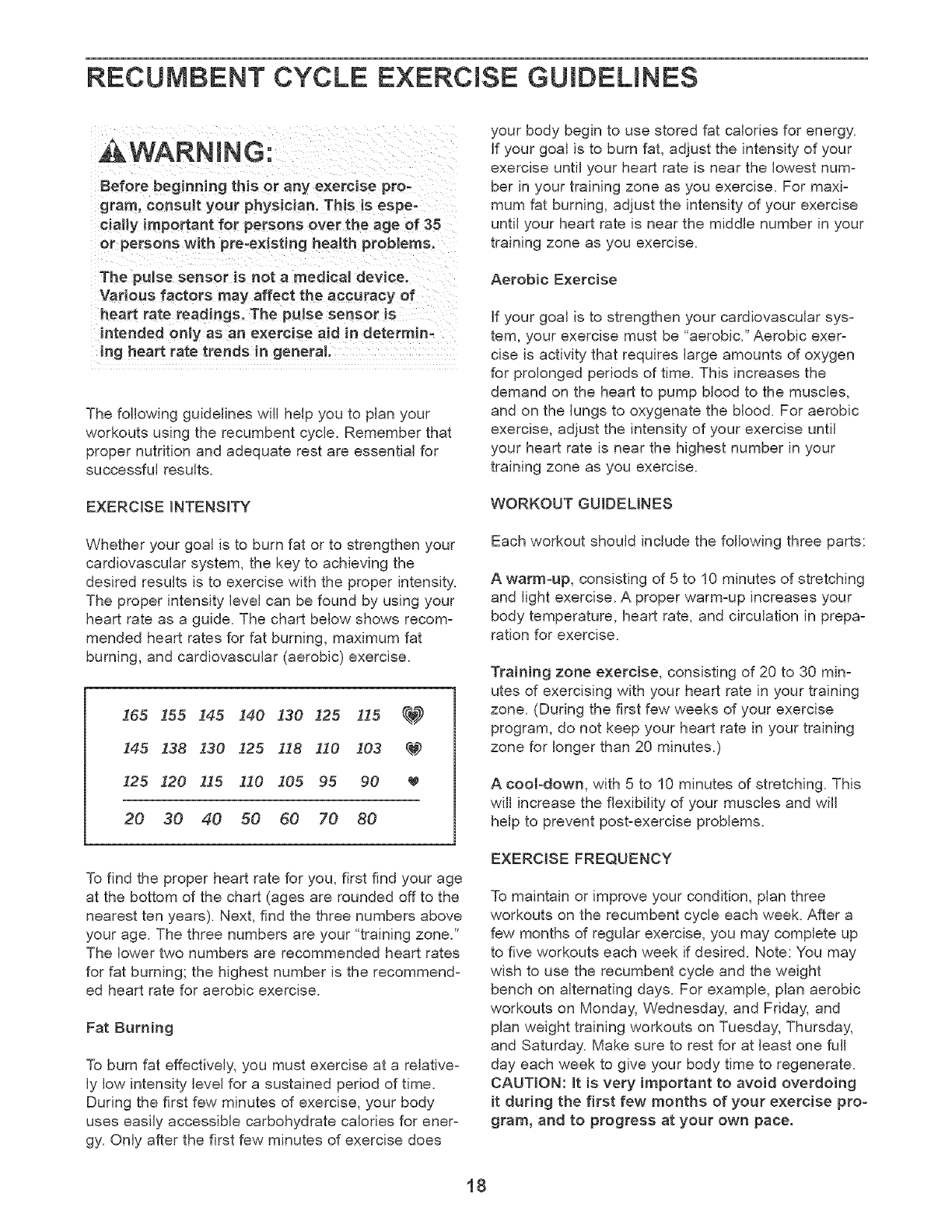
265 155 145 140 130 125 115 _
145 138 130 I25 118 !i0 103 q_#2
125 120 115 110 105 95 90
20 30 40 50 60 70 80
To find the proper heart rate for you, first find your age
at the bottom of the chart (ages are rounded off to the
nearest ten years). Next, find the three numbers above
your age. The three numbers are your "training zone."
The lower two numbers are recommended heart rates
for fat burning; the highest number is the recommend-
ed heart rate for aerobic exercise.
Fat Burning
To burn fat effectively, you must exercise at a relative=
ly low intensity level for a sustained period of time.
During the first few minutes of exercise, your body
uses easily accessible carbohydrate calories for ener-
gy. Only after the first few minutes of exercise does
your body begin to use stored fat calories for energy.
If your goal is to burn fat, adjust the intensity of your
exercise until your heart rate is near the lowest num=
bet in your training zone as you exercise. For maxi-
mum fat burning, adjust the intensity of your exercise
until your heart rate is near the middle number in your
training zone as you exercise.
Aerobic Exercise
If your goal is to strengthen your cardiovascular sys=
tern, your exercise must be "aerobic." Aerobic exer=
cise is activity that requires large amounts of oxygen
for prolonged periods of time. This increases the
demand on the heart to pump blood to the muscles,
and on the lungs to oxygenate the blood. For aerobic
exercise, adjust the intensity of your exercise until
your heart rate is near the highest number in your
training zone as you exercise.
WORKOUT GUiDELiNES
Each workout should include the following three parts:
A warm-up, consisting of 5 to 10 minutes of stretching
and light exercise. A proper warm-up increases your
body temperature, heart rate, and circulation in prepa=
ration for exercise.
Training zone exercise, consisting of 20 to 30 min-
utes of exercising with your heart rate in your training
zone. (During the first few weeks of your exercise
program, do not keep your heart rate in your training
zone for longer than 20 minutes.)
A cool-down, with 5 to 10 minutes of stretching. This
will increase the flexibility of your muscles and will
help to prevent post=exercise problems.
EXERCISE FREQUENCY
To maintain or improve your condition, plan three
workouts on the recumbent cycle each week. After a
few months of regular exercise, you may complete up
to five workouts each week if desired. Note: You may
wish to use the recumbent cycle and the weight
bench on alternating days. For example, plan aerobic
workouts on Monday, Wednesday, and Friday, and
plan weight training workouts on Tuesday, Thursday,
and Saturday. Make sure to rest for at least one fuji
day each week to give your body time to regenerate.
CAUTION: it is very important to avoid overdoing
it during the first few months of your exercise pro=
gram, and to progress at your own pace.
18
WEIGHT BENCH EXERCISE GUIDELINES
exercise program, cOnsu!t your physician,
THS is especja!!y important for persons over
the age of 35 or persons with pre,existing
health ptobJems.
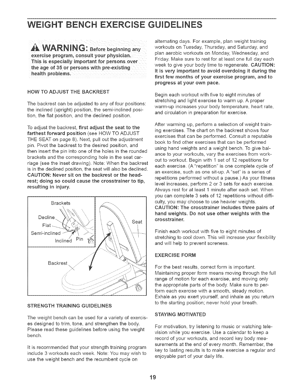
HOW TO ADJUST THE BACKREST
The backrest can be adjusted to any of four positions:
the inclined (upright) position, the semi=inclined posi=
tion, the flat position, and the declined position.
To adjust the backrest, first adjust the seat to the
farthest fot_vard position (see HOW TO ADJUST
THE SEAT on page 8). Next, pull out the adjustment
pin. Pivot the backrest to the desired position, and
then insert the pin into one of the holes in the rounded
brackets and the corresponding hole in the seat car=
riage (see the inset drawing). Note: When the backrest
is in the declined position, the seat will also be declined.
CAUTION: Never sit on the backrest or the head-
rest; doing so could cause the crosstrainer to tip,
resulting in injury.
Brackets
\
Decline..
Flat
Semi-inclined
Inclined Pin
STRENGTH TRAINING GUIDELINES
The weight bench can be used for a variety of exercis=
es designed to trim, tone, and strengthen the body.
Please read these guidelines before using the weight
bench.
It is recommended that your strength training program
include 3 workouts each week. Note: You may wish to
use the weight bench and the recumbent cycle on
alternating days. For example, plan weight training
workouts on Tuesday, Thursday, and Saturday, and
plan aerobic workouts on Monday, Wednesday, and
Friday. Make sure to rest for at least one full day each
week to give your body time to regenerate. CAUTION:
it is very important to avoid overdoing it during the
first few months of your exercise program, and to
progress at your own pace.
Begin each workout with five to eight minutes of
stretching and light exercise to warm up. A proper
warm=up increases your body temperature, heart rate,
and circulation in preparation for exercise.
After warming up, perform a selection of weight train-
ing exercises. The chart on the backrest shows four
exercises that can be performed. Consult a reputable
book to find other exercises that can be performed
using hand weights and a weight bench. To give bal-
ance to your workouts, vary the exercises from work-
out to workout. Begin with 1 set of 12 repetitions for
each exercise. (A "repetition" is one complete cycle of
an exercise, such as one sit=up. A "set" is a series of
repetitions performed without a pause.)As your fitness
level increases, perform 2 or 3 sets for each exercise.
Always rest for at least 1 minute after each set. When
you can complete 3 sets of 12 repetitions without diffi=
culty, you may choose to use heavier weights.
CAUTION: The crosstrainer includes three pairs of
hand weights. Do not use other weights with the
crosstrainer.
Finish each workout with five to eight minutes of
stretching to cool down. This will increase your flexibility
and will help to prevent soreness.
EXERCISE FORM
For the best results, correct form is important.
Maintaining proper form means moving through the full
range of motion for each exercise, and moving only
the appropriate parts of the body. Make sure to per=
form each exercise with a smooth, steady motion.
Exhale as you exert yourself, and inhale as you return
to the starting position; never hold your breath.
STAYING MOTIVATED
For motivation, try listening to music or watching tele=
vision while you exercise. Use a calendar to keep a
record of your workouts, and record key body mea=
surements at the end of every month. Remember, the
key to lasting results is to make exercise a regular and
enjoyable part of your daily life.
19
SUGGESTED STRETCHES
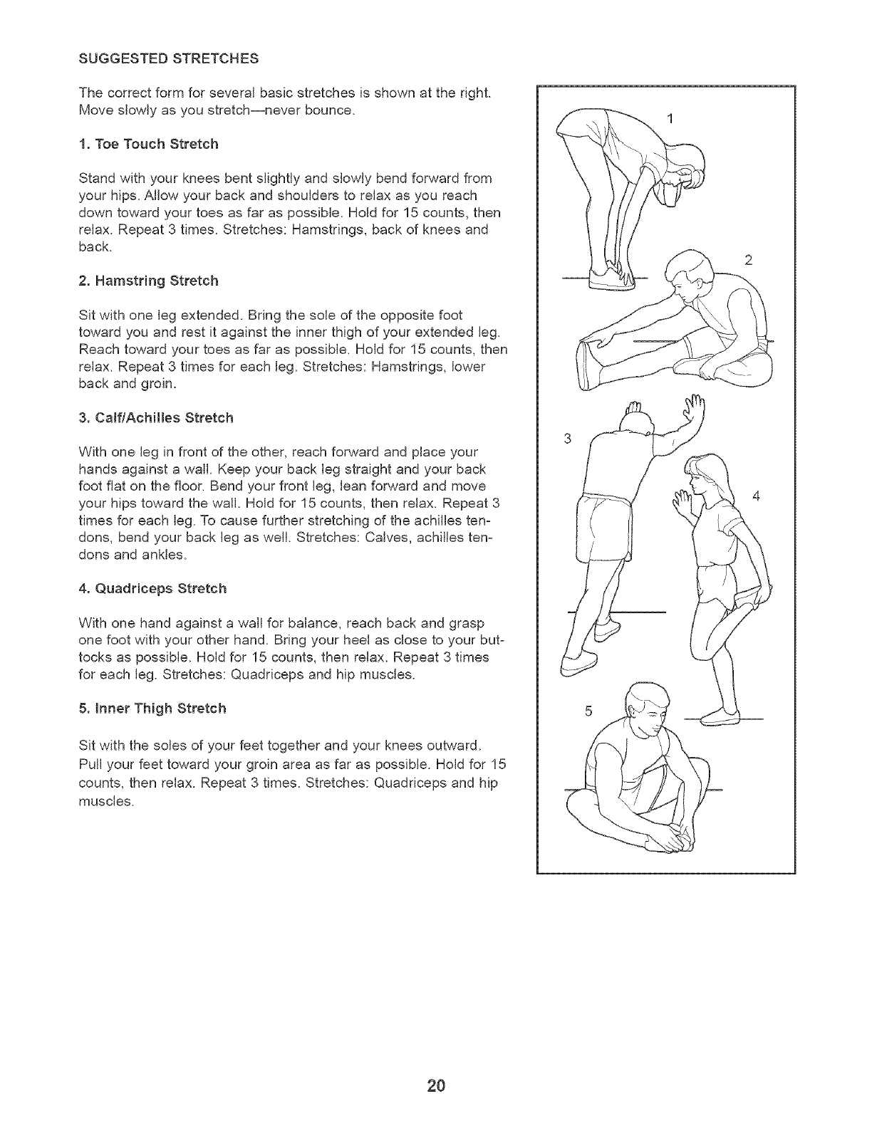
The correct form for several basic stretches is shown at the right.
Move slowly as you stretch--never bounce.
1. Toe Touch Stretch
Stand with your knees bent slightly and slowly bend forward from
your hips. Allow your back and shoulders to relax as you reach
down toward your toes as far as possible. Hold for 15 counts, then
relax. Repeat 3 times. Stretches: Hamstrings, back of knees and
back.
2. Hamstr{ng Stretch
Sit with one leg extended. Bring the sole of the opposite foot
toward you and rest it against the inner thigh of your extended leg.
Reach toward your toes as far as possible. Hold for 15 counts, then
relax. Repeat 3 times for each leg. Stretches: Hamstrings, lower
back and groin.
3. CamflAchHJes Stretch
With one leg in front of the other, reach forward and place your
hands against a wall. Keep your back leg straight and your back
foot flat on the floor. Bend your front leg, lean forward and move
your hips toward the wall. Hold for 15 counts, then relax. Repeat 3
times for each leg. To cause further stretching of the achilles ten-
dons, bend your back leg as well. Stretches: Calves, achilles ten-
dons and ankles.
4. Quadriceps Stretch
With one hand against a wall for balance, reach back and grasp
one foot with your other hand. Bring your heel as close to your but-
tocks as possible. Hold for 15 counts, then relax. Repeat 3 times
for each leg. Stretches: Quadriceps and hip muscles.
5. Inner Thigh Stretch
Sit with the soles of your feet together and your knees outward.
Pull your feet toward your groin area as far as possible. Hold for 15
counts, then relax. Repeat 3 times. Stretches: Quadriceps and hip
muscles.
2O
MAINTENANCE AND TROUBLESHOOTING
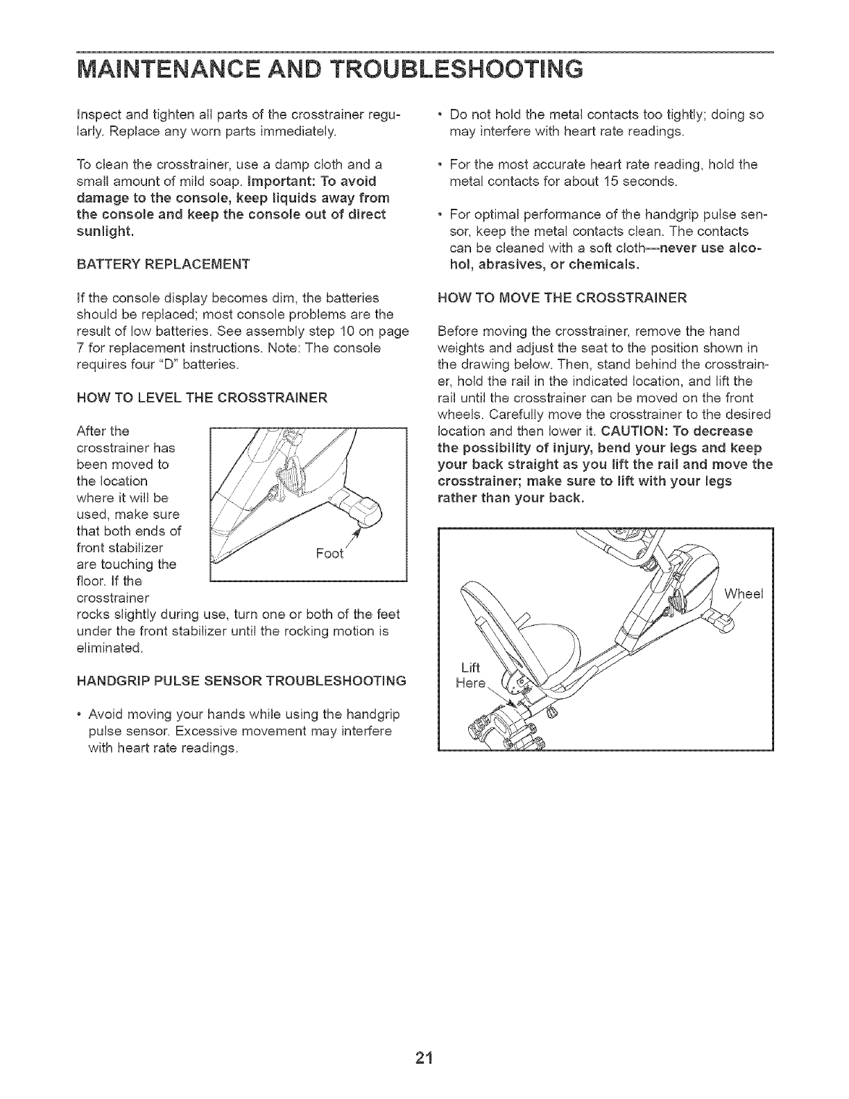
Inspect and tighten all parts of the crosstrainer regu-
larly. Replace any worn parts immediately.
To clean the crosstrainer, use a damp cloth and a
small amount of mild soap. important: To avoid
damage to the console, keep liquids away from
the console and keep the console out of direct
sunlight.
BATTERY REPLACEMENT
If the console display becomes dim, the batteries
should be replaced; most console problems are the
result of low batteries. See assembly step 10 on page
7 for replacement instructions. Note: The console
requires four "D" batteries.
HOW TO LEVEL THE CROSSTRAINER
After the
crosstrainer has
been moved to
the location
where it will be
used, make sure
that both ends of
front stabilizer Foot
are touching the
floor, if the
crosstrainer
rocks slightly during use, turn one or both of the feet
under the front stabilizer until the rocking motion is
eliminated.
HANDGRIP PULSE SENSOR TROUBLESHOOTING
•Avoid moving your hands while using the handgrip
pulse sensor. Excessive movement may interfere
with heart rate readings.
•Do not hold the metal contacts too tightly; doing so
may interfere with heart rate readings.
•For the most accurate heart rate reading, hold the
metal contacts for about 15 seconds.
•For optimal performance of the handgrip pulse sen-
sor, keep the metal contacts clean. The contacts
can be cleaned with a soft cloth--never use alco-
hol, abrasives, or chemicals.
HOW TO MOVE THE CROSSTRAINER
Before moving the crosstrainer, remove the hand
weights and adjust the seat to the position shown in
the drawing below. Then, stand behind the crosstrain-
er, hold the rail in the indicated location, and lift the
rail until the crosstrainer can be moved on the front
wheels. Carefully move the crosstrainer to the desired
location and then lower it. CAUTION: To decrease
the possibility of injury, bend your legs and keep
your back straight as you lift the rait and move the
crosstrainer; make sure to lift with your legs
rather than your back.
Wheel
21

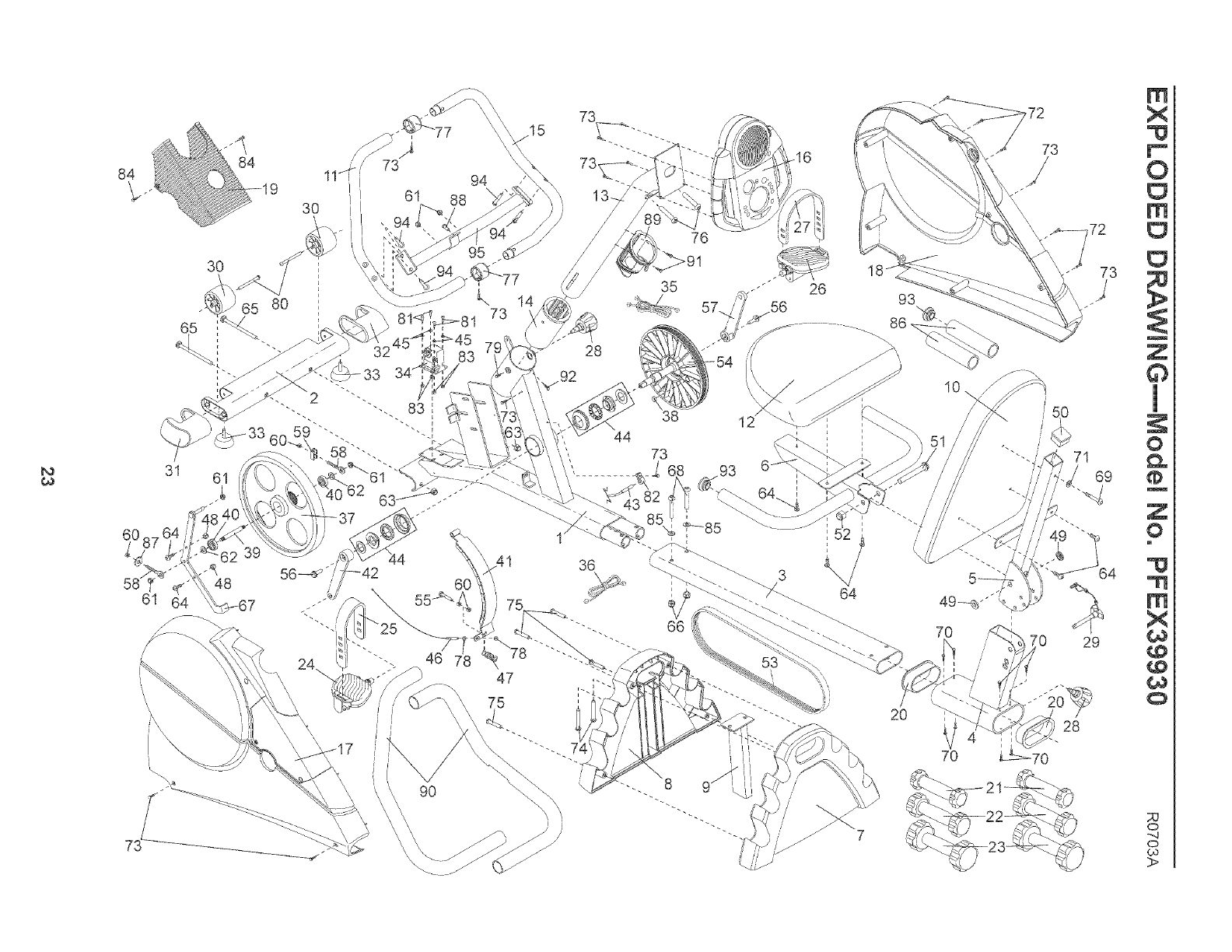
PART LiST--Model No. PFEX39930 R0703A
Key No. Qty. Description Key No. Qty. Description
1 1 Frame 50 1
2 1 Front Stabilizer 51 1
3 1 Frame Extension 52 1
4 1 Seat Carriage 53 1
5 1 Backrest Frame 54 1
6 1 Seat Frame 55 1
7 1 Rear Stabilizer Cover 56 2
8 1 Front Stabilizer Cover 57 1
9 1 Rear Stabilizer 58 2
10 1 Backrest 59 1
11 1 Left Handlebar 60 4
12 1 Seat 61 5
13 1 Upright 62 2
14 1 Upright Bushing 63 2
15 1 Right Handlebar 64 7
16 1 Console 65 2
17 1 Left Side Shield 66 2
18 1 Right Side Shield 67 1
19 1 Side Shield Cover 68 2
20 2 Seat Carriage Bushing 69 1
21 2 Small Hand Weight 70 8
22 2 Medium Hand Weight 71 1
23 2 Large Hand Weight 72 5
24 1 Left Pedal 73 12
25 1 Left Pedal Strap 74 2
26 1 Right Pedal 75 4
27 1 Right Pedal Strap 76 2
28 2 Adjustment Knob 77 2
29 1 Adjustment Pin 78 2
30 2 Wheel 79 1
31 1 Left Front Endcap 80 2
32 1 Right Front Endcap 81 4
33 2 Foot 82 1
34 1 Adjustment Motor 83 4
35 1 Upper Wire Harness 84 2
36 1 Lower Wire Harness 85 2
37 1 Flywheel 86 2
38 1 Magnet 87 1
39 1 Flywheel Axle 88 1
40 2 Flywheel Bearing 89 1
41 1 "C" Magnet 90 2
42 1 Left Crank Arm 91 2
43 1 Reed Switch/Wire 92 1
44 1 Crank Bearing Assembly 93 2
45 4 M5 Flat Washer 94 4
46 1 Adjustment Cable 95 1
47 1 Return Spring # 1
48 2 M6 Nylon Locknut # 3
49 2 Seat Bushing
Backrest Frame Endcap
1/2" x 70mm Button Bolt
1/2" Nylon Locknut
Belt
Pulley/Crank
M6 x 25mm Bolt
Flange Screw
Right Crank Arm
M6 Eyebolt
"U" Bracket
M6 Nut
M8 Nylon Locknut
Flywheel Washer
MI0 Black Nylon Locknut
M6 x 16mm Screw
M10 x 112mm Carriage Bolt
MI0 Zinc Nylon Locknut
"C" Magnet Bracket
MI0 x 52mm Zinc Button Bolt
M6 x 50mm Screw
M5 x 7mm Screw
M6 Flat Washer
M4 x 25mm Screw
M4 x 16mm Screw
M10 x 45mm Button Screw
M4 x 38mm Round Head Screw
M8 x 39mm Button Bolt
Handlebar Collar
M5 Nut
M6 x 25.4mm Button Screw
M6 x 72mm Button Screw
M5 x 12mm Bolt
Reed Switch Clamp
M5 Nylon Locknut
M4 x 12mm Round Head Screw
M10 Zinc Split Washer
Foam Grip
M6 Large Washer
M8 x 14mm Button Screw
Water Bottle Holder
Handlebar Foam
M4 x 22mm Screw
M4 x 8mm Screw
Seat Frame Endcap
M8 x 12mm Button Screw
Handlebar Bracket
User's Manual
Allen Wrench
Note: "#' indicates a non-illustrated part. Specifications are subject to change without notice. See the back cover
of this manual for information about ordering replacement parts.
22
¢¢
84
3O
30
65 80
31 61
60
48
61
73
61
/32
94
88
73 14
47
75
73
28
44
36
35
38 12
73
20
93
10
7O
7O
j[
/50
71
69
0 29
28
70
R1
X
"U
O
R1
Z
1
O
w
Z
O
R1
X
¢¢
P0
O
,,,,4
O

HOW TO ORDER REPLACEMENT PARTS
To order replacement parts, call our Customer Service Department tollzfree at 1z800_999_3756, Monday through
Friday, 6 a.m. until 6 p.m. Mountain Time (excluding holidays). To help us assist you, please be prepared to give
the following information:
•The MODEL NUMBER of the product (PFEX39930)
•The NAME of the product (PROFORM _'CROSSTRAINER 55)
•The SERIAL NUMBER of the product (see the front cover of this manual)
•The KEY NUMBER and DESCRiPTiON of the part(s) (see the PART LiST on page 22)
PROFORM is a registered trademark of iCON Health & Fitness, inc.
LiMiTED WARRANTY
iCON Health & Fitness, Inc. (ICON), warrants this product to be free from defects in workmanship and
material, under normal use and service conditions, for a period of ninety (90) days from the date of pur-
chase. This warranty extends only to the original purchaser, iCON's obligation under this warranty is lim-
ited to replacing or repairing, at ICON's option, the product through one of its authorized service centers.
All repairs for which warranty claims are made must be prezauthorized by iCON. This warranty does not
extend to any product or damage to a product caused by or attributable to freight damage, abuse, mis-
use, improper or abnormal usage or repairs not provided by an ICON authorized service center, products
used for commercial or rental purposes, or products used as store display models. No other warranty
beyond that specifically set forth above is authorized by ICON.
ICON is not responsible or liable for indirect, special or consequential damages arising out of or in con-
nection with the use or performance of the product or damages with respect to any economic loss, loss
of property, loss of revenues or profits, loss of enjoyment or use, costs of removal, installation or other
consequential damages of whatsoever nature. Some states do not allow the exclusion or limitation of inci-
dental or consequential damages. Accordingly, the above limitation may not apply to you.
The warranty extended hereunder is in lieu of any and all other warranties and any implied warranties of
merchantability or fitness for a particular purpose is limited in its scope and duration to the terms set forth
herein. Some states do not allow limitations on how long an implied warranty lasts. Accordingly, the above
limitation may not apply to you.
This warranty gives you specific legal rights. You may also have other rights which vary from state to state.
iCON HEALTH & FITNESS, INC., 1800 S. 1000 W., LOGAN, UT 84321-9813
Part No. 198386 R0703A Printed in China © 2003 ICON Health and Fitness, Inc.
