Proform 218221 Owner S Manual 285430
2014-07-06
: Proform Proform-218221-Owner-S-Manual proform-218221-owner-s-manual proform pdf
Open the PDF directly: View PDF ![]() .
.
Page Count: 20
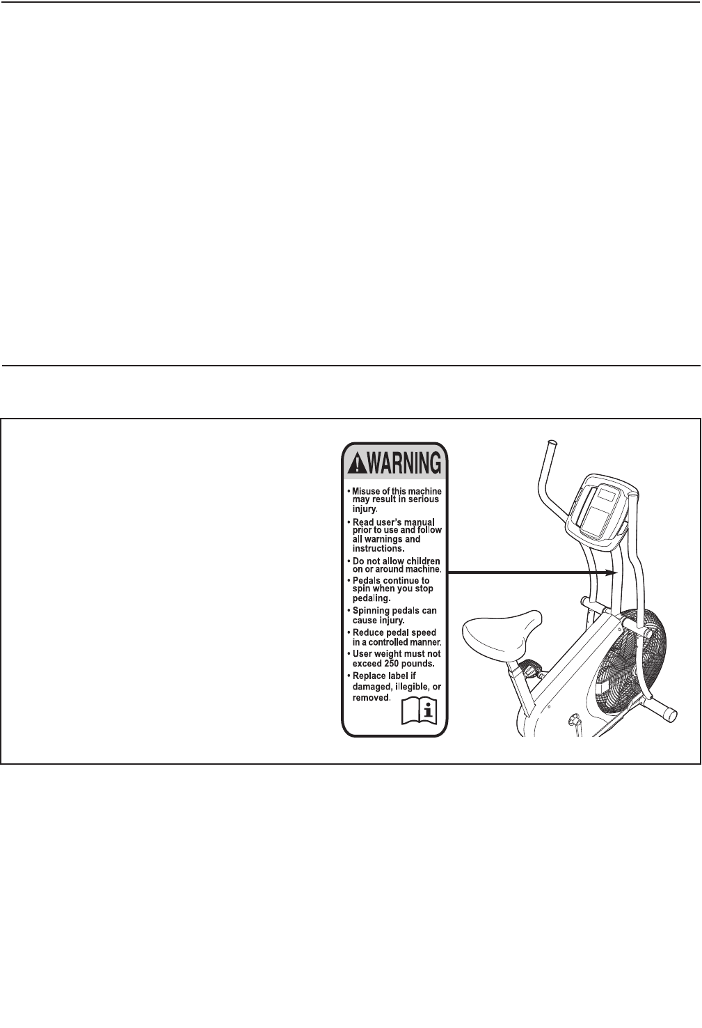
CAUTION
Read all precautions and instruc-
tions in this manual before using
this equipment. Keep this manual
for future reference.
Serial Number
Decal
• Assembly
• Operation
• Maintenance
• Part List and Drawing
BIKE EXERCISER
Userʼs Manual
Model No. 831.21822.1
Serial No.
Write the serial number in the
space above for reference.
Sears, Roebuck and Co.
Hoffman Estates, IL 60179
2
TABLE OF CONTENTS
WARNINGDECALPLACEMENT ..............................................................2
IMPORTANTPRECAUTIONS ................................................................3
BEFOREYOUBEGIN ......................................................................4
ASSEMBLY ...............................................................................5
HOWTOUSETHEEXERCISECYCLE........................................................11
MAINTENANCEANDTROUBLESHOOTING ...................................................14
EXERCISEGUIDELINES ...................................................................16
PARTLIST ..............................................................................18
EXPLODEDDRAWING ....................................................................19
ORDERINGREPLACEMENTPARTS ..................................................BackCover
90DAYFULLWARRANTY ..........................................................BackCover
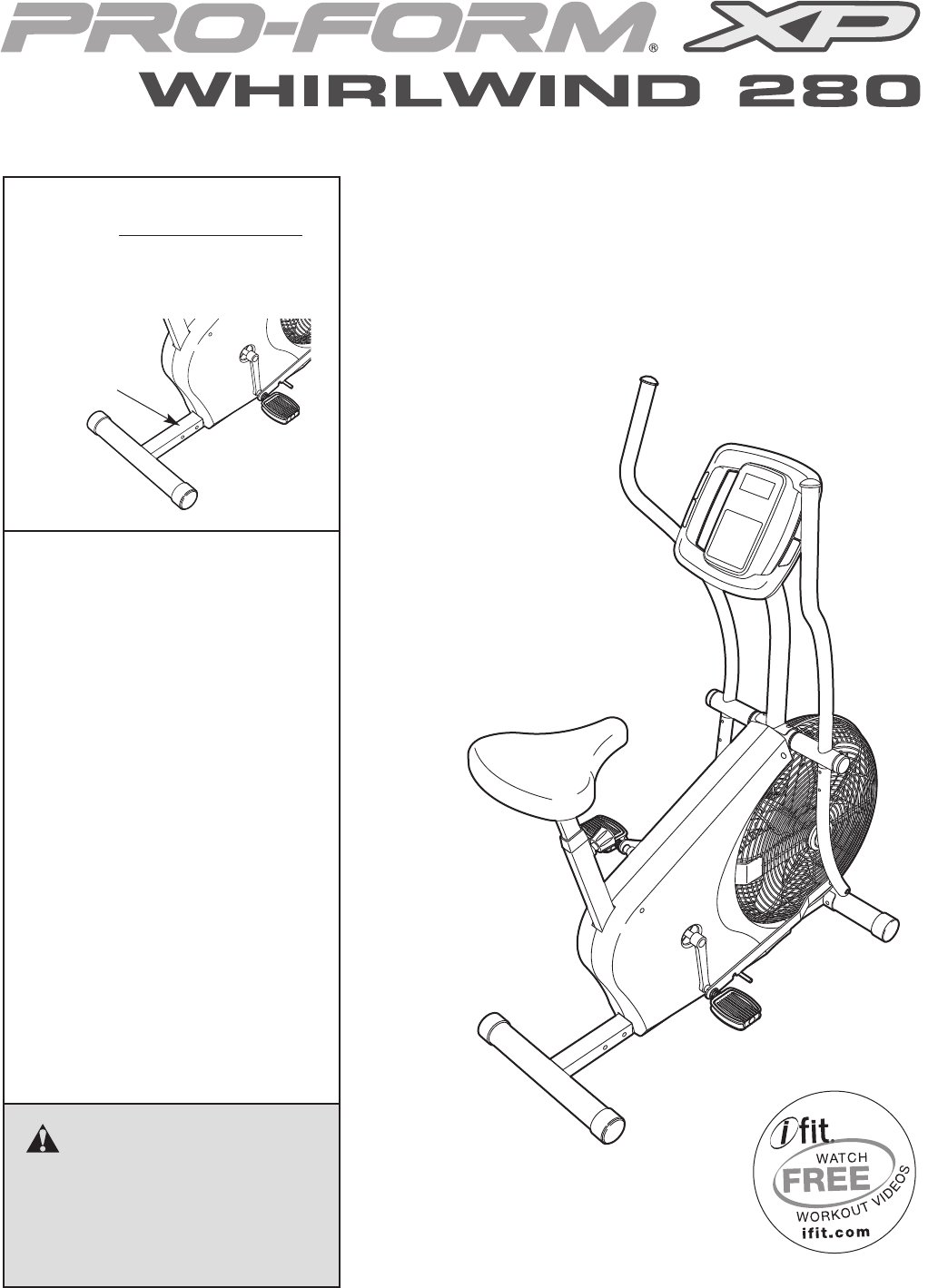
WARNING DECAL PLACEMENT
This drawing shows the location(s) of the
warning decal(s). If a decal is missing or
illegible, call 1-888-533-1333 and request a
free replacement decal. Apply the decal in
the location shown. Note: The decal(s) may
not be shown at actual size.

3
WARNING: To reduce the risk of serious injury, read all important precautions and
instructions in this manual and all warnings on your exercise cycle before using your exercise
cycle. Sears assumes no responsibility for personal injury or property damage sustained by or
through the use of this product.
IMPORTANT PRECAUTIONS
1. Before beginning any exercise program,
consult your physician. This is especially
important for persons over age 35 or per-
sons with pre-existing health problems.
2. It is the responsibility of the owner to ensure
that all users of the exercise cycle are ade-
quately informed of all precautions.
3. The exercise cycle is intended for home use
only. Do not use the exercise cycle in a com-
mercial, rental, or institutional setting.
4. Keep the exercise cycle indoors, away from
moisture and dust. Place the exercise cycle
on a level surface, with a mat beneath it to
protect the floor or carpet. Make sure that
there is at least 2 ft. (0.6 m) of clearance
around the exercise cycle.
5. Inspect and properly tighten all parts regular-
ly. Replace any worn parts immediately.
6. Keep children under age 12 and pets away
from the exercise cycle at all times.
7. The exercise cycle should not be used by
persons weighing more than 250 lbs.
(113 kg).
8. Wear appropriate exercise clothes while
exercising; do not wear loose clothes that
could become caught on the exercise cycle.
Always wear athletic shoes for foot protec-
tion while exercising.
9. When adjusting the seat, insert the adjust-
ment knob into one of the holes in the seat
post. Do not insert the seat pin under the
seat post.
10. The pulse sensor is not a medical device.
Various factors, including the user's move-
ment, may affect the accuracy of heart rate
readings. The pulse sensor is intended only
as an exercise aid in determining heart rate
trends in general.
11. Keep your back straight while using the exer-
cise cycle; do not arch your back.
12. When you stop exercising, allow the pedals
to slowly come to a stop.
13. Over exercising may result in serious injury
or death. If you feel faint or if you experience
pain while exercising, stop immediately and
cool down.
14. Use the exercise cycle only as described in
this manual.
15. When connecting the link arms to the pedals,
make sure that the link arms are fully seated
on the pedal bushings (see HANDLEBAR
OPERATION on page 11). If the link arms are
not on the pedal bushings, they may slip off
during use, resulting in injury to the user.
16. When adjusting the height of the seat, make
sure that the pin on the seat knob is inserted
into one of the adjustment holes in the seat
post (see HOW TO ADJUST THE SEAT on
page 11). Do not rest the seat post on top of
the pin on the seat knob.
4
Congratulations for selecting the new PROFORM®XP
WHIRLWIND 280 exercise cycle. Cycling is one of the
most effective exercises for increasing cardiovascular
fitness, building endurance, and toning the entire body.
The XP WHIRLWIND 280 exercise cycle offers an
array of features designed to let you enjoy this health-
ful exercise in the comfort and privacy of your home.
For your benefit, read this manual carefully before
you use the exercise cycle. If you have questions
after reading this manual, please see the back cover
of this manual. To help us assist you, note the product
model number and serial number before contacting
us. The model number and the location of the serial
number decal are shown on the front cover of this
manual.
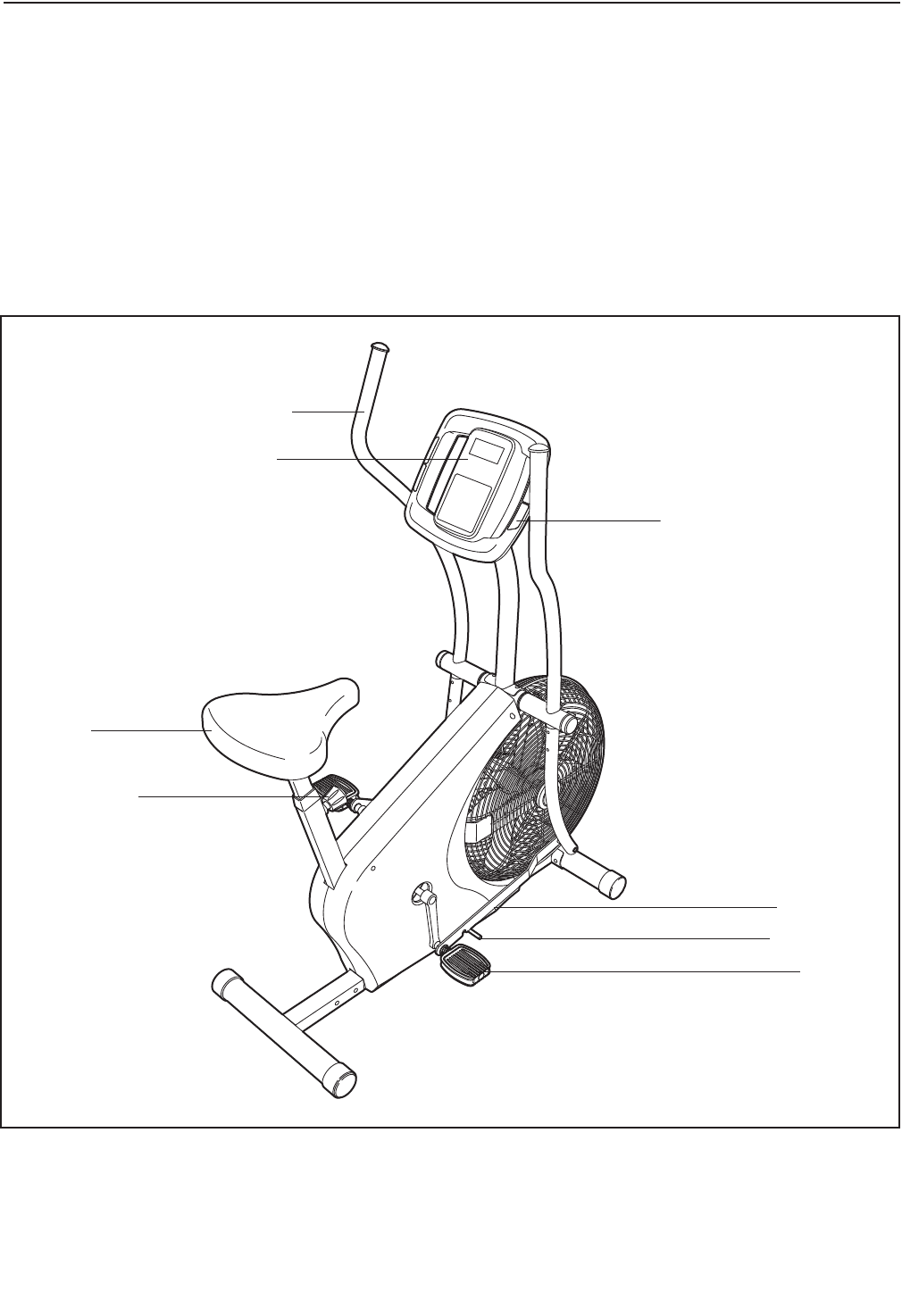
Before reading further, please familiarize yourself with
the parts that are labeled in the drawing below.
Handgrip Pulse Sensor
Handlebar
Seat
Lock Rod
Pedal
Console
Seat Knob
Link Arm
BEFORE YOU BEGIN
5
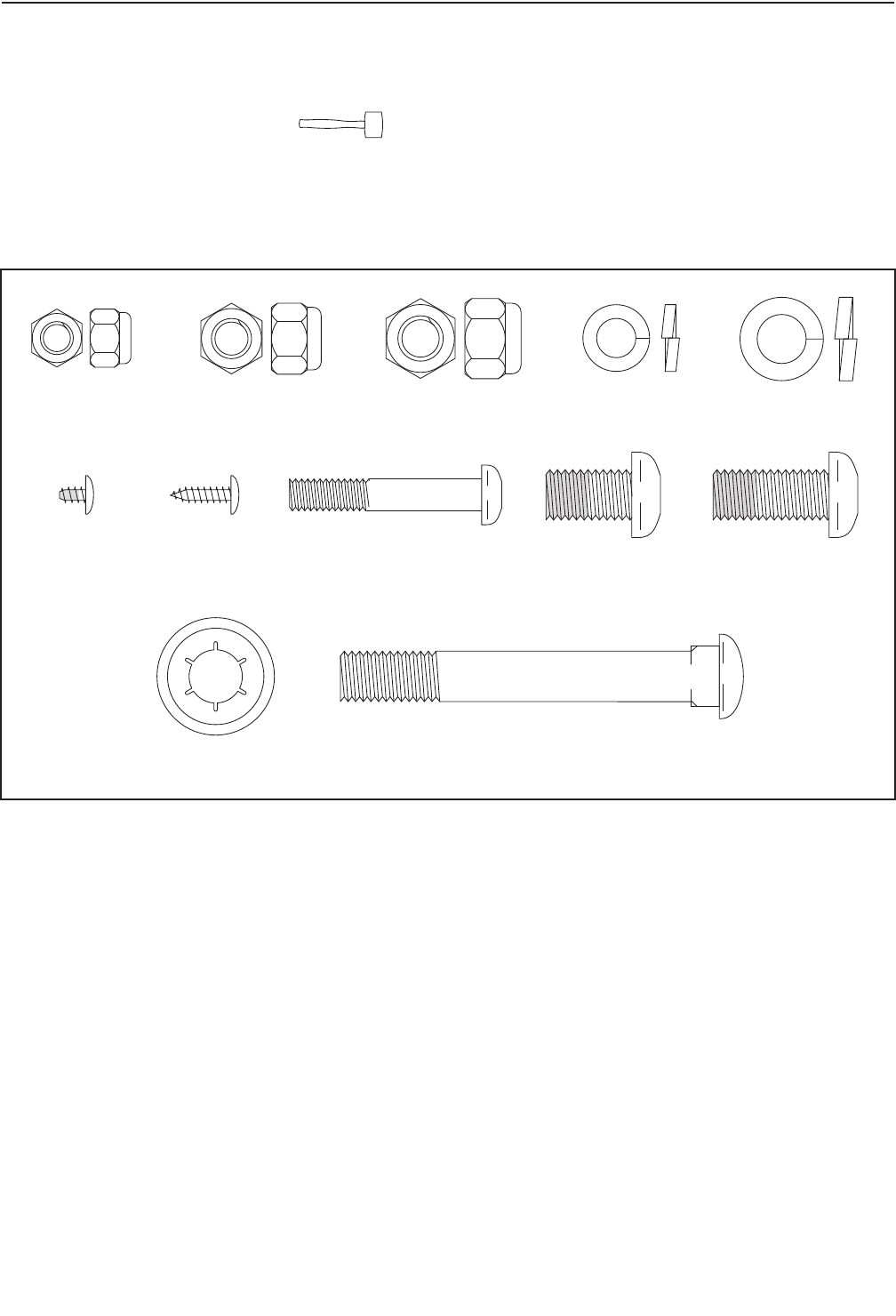
M8 Split
Washer (72)–4
M6 Locknut
(56)–4
M8 Locknut
(66)–4
M10 Locknut
(64)–2
M10 Split
Washer (54)–9
M10 x 75mm Carriage Bolt (65)–2Push Nut (78)–2
M6 x 38mm Button
Bolt (57)–4
M10 x 17mm Patch
Screw (55)–3
M10 x 22mm Patch
Screw (4)–6
M4 x 5mm
Patch Screw
(70)–1
M4 x 16mm
Screw (77)–4
ASSEMBLY
Assembly requires two persons. Place all parts of the exercise cycle in a cleared area and remove the pack-
ing materials. Do not dispose of the packing materials until assembly is completed. Assembly requires the
included tools and a rubber mallet .
Use the part drawings below to identify the small parts used in assembly. The number in parentheses below
each drawing refers to the key number of the part, from the PART LIST near the end of this manual. The number
following the parentheses is the quantity needed for assembly. Note: If a part is not in the hardware kit,
check to see if it has been preassembled. If a part is missing, call 1-888-533-1333.
6
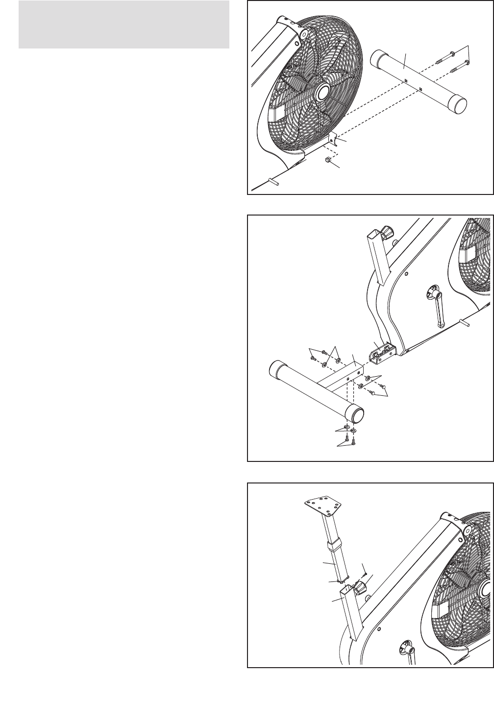
65
1.
Attach the Front Stabilizer (19) to the front of
the Frame (1) with two M10 x 75mm Carriage
Bolts (65) and two M10 Locknuts (64).
19
64
1
1
2. Attach the Rear Stabilizer (60) to the Frame (1)
with six M10 x 22mm Patch Screws (4) and six
M10 Split Washers (54).
60
54
54
54
1
4
4
4
2
To make assembly easier, read the
information on page 5 before you begin
assembling the exercise cycle.
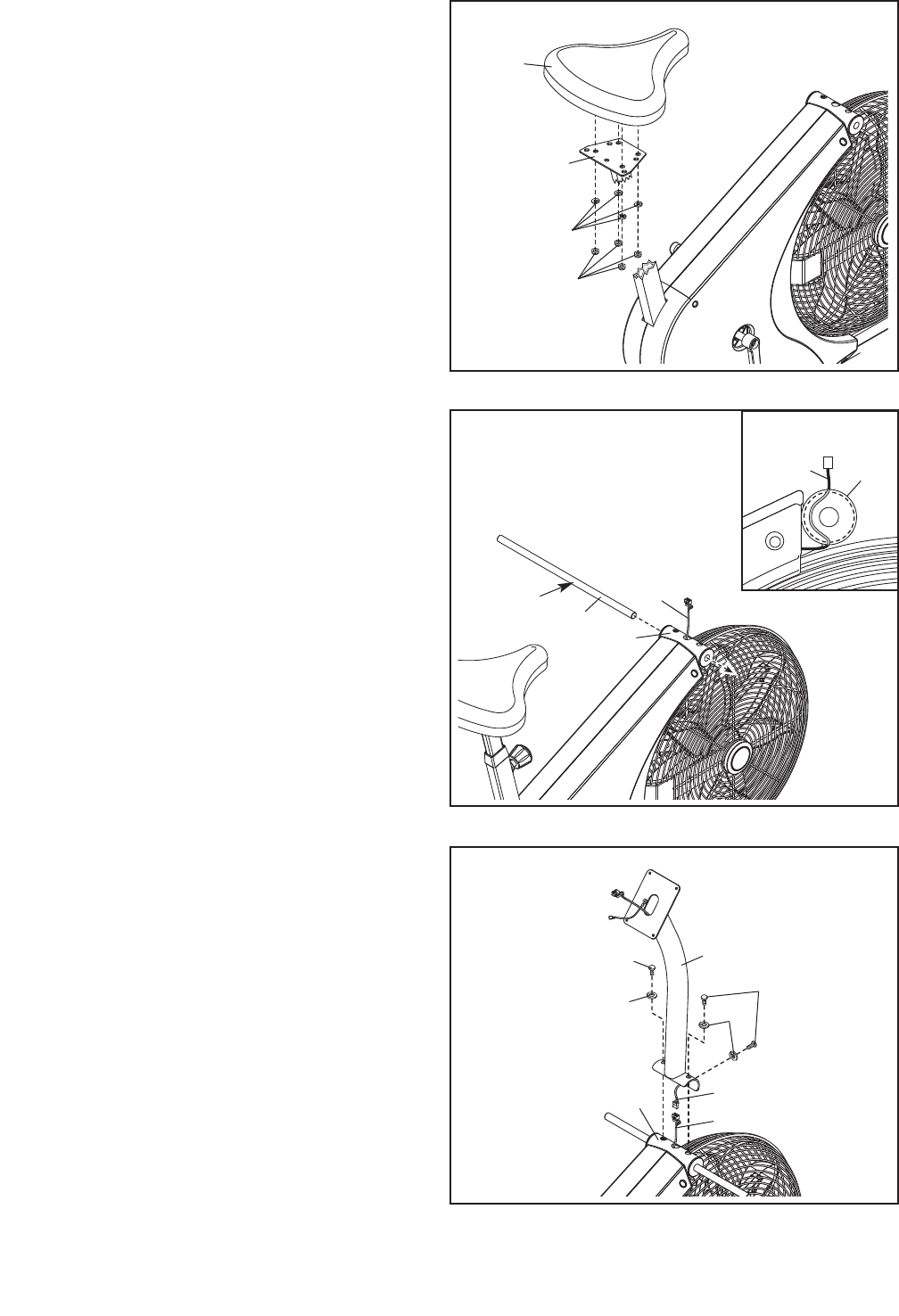
3. Loosen the Seat Knob (29) a few turns. Next,
pull the Seat Knob outward, insert the Seat Post
(6) into the Frame (1), and then release the
Seat Knob. Move the Seat Post upward and
downward slightly to make sure that the pin
on the Seat Knob is engaged in one of the
adjustment holes in the Seat Post.
Next, push the Seat Guide (46) into the top of
the Frame (1). Attach the Seat Guide with an
M4 x 5mm Patch Screw (70). Then, retighten
the Seat Knob (29).
3
6
1
46
70
29
7
4. Attach the Seat (20) to the Seat Post (6) with
four M8 Locknuts (66) and four M8 Split
Washers (72). Note: The Locknuts and Split
Washers may be preattached to the under-
side of the Seat.
4
20
72
66
6
5. Tip: To avoid pinching the Reed Switch Wire
(31), position it as shown in the inset draw-
ing.
Apply a small amount of the included grease to
the Handlebar Axle (33). Insert the Handlebar
Axle into the Frame (1) and center it. Note: It
may be helpful to use a rubber mallet to
insert the Handlebar Axle.
5
31
1
Grease
33
Do not pinch the Reed
Switch Wire (31)
6
6. While another person holds the Upright (2) near
the Frame (1), connect the Reed Switch Wire
(31) to the Extension Wire (39).
Tip: Do not pinch the Reed Switch Wire (31)
or the Extension Wire (39). Set the Upright (2)
on the Frame (1). Attach the Upright with three
M10 x 17mm Patch Screws (55) and three M10
Split Washers (54).
55
54 54
55
2
139
31
31 1
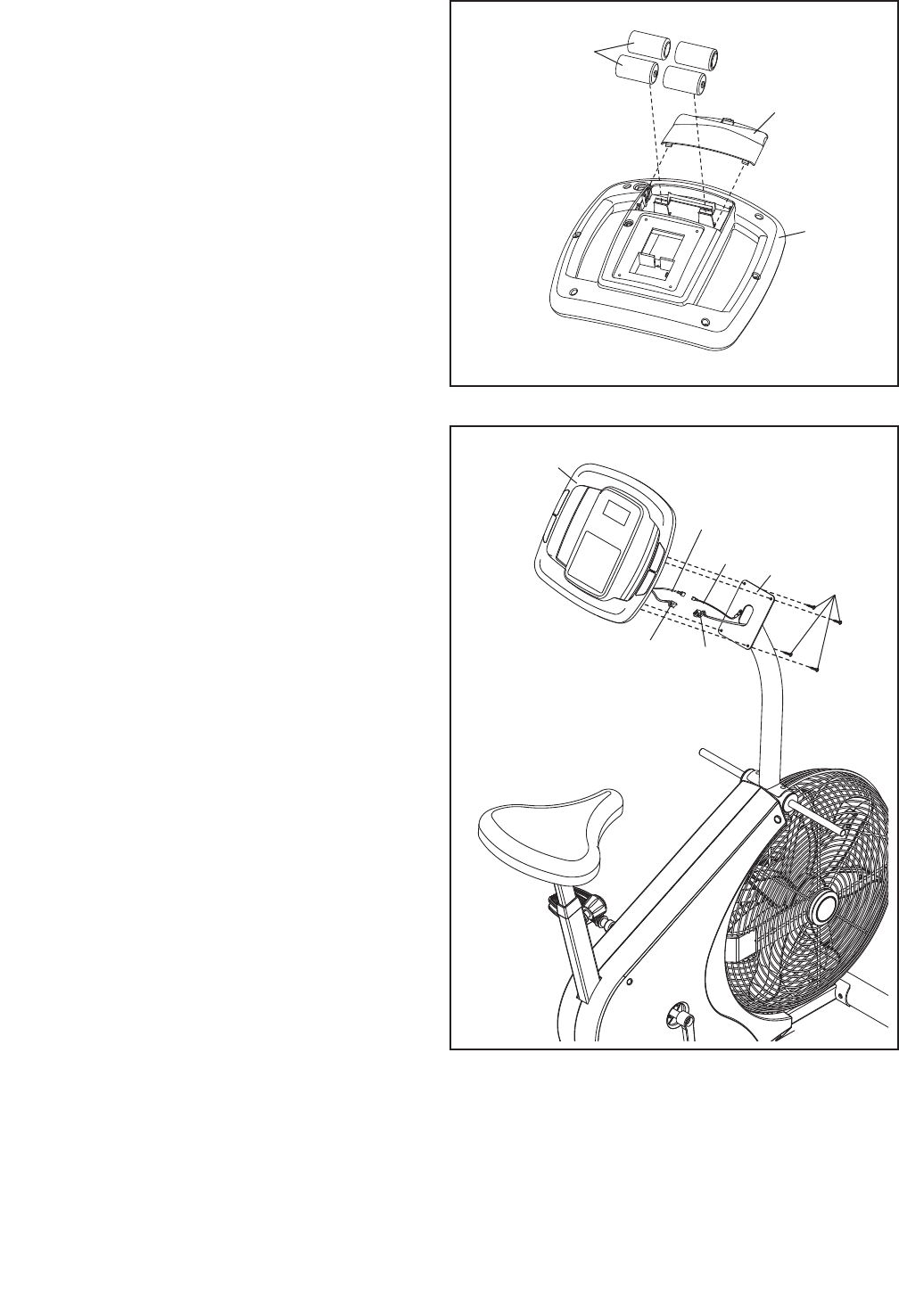
8
7. The Console (3) requires four “D” batteries (not
included); alkaline batteries are recommended.
IMPORTANT: If the Console has been
exposed to cold temperatures, allow it to
warm to room temperature before inserting
batteries. Otherwise, you may damage the
console displays or other electronic compo-
nents. Remove the battery cover, insert the
batteries into the battery compartment, and
reattach the battery cover. Make sure to orient
the batteries as shown by the diagram
inside the battery compartment. 3
Battery
Cover
Batteries
7
83
Console
Wire
Ground
Wire
8. While another person holds the Console (3)
near the Upright (2), connect the console wire
to the Extension Wire (39). Then, connect the
console ground wire to the Ground Wire (80)
Insert the excess wire into the Upright.
Tip: Do not pinch the wires. Attach the
Console (3) to the Upright (2) with four M4 x
16mm Screws (77).
Do not pinch
the wires
2
77
39
80
9
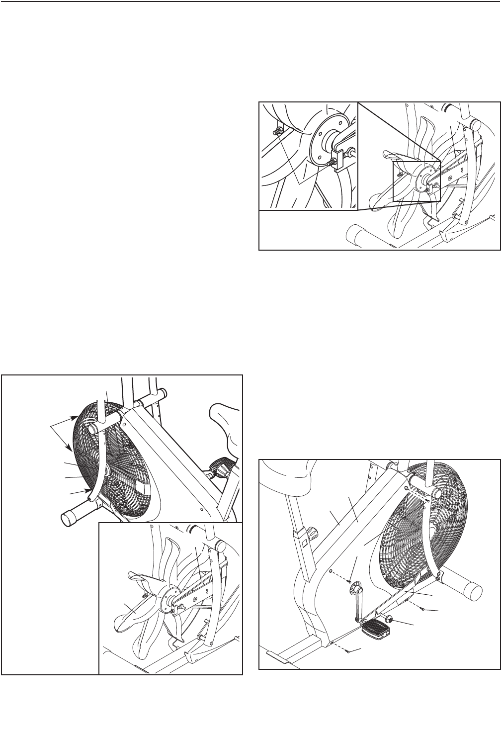
10
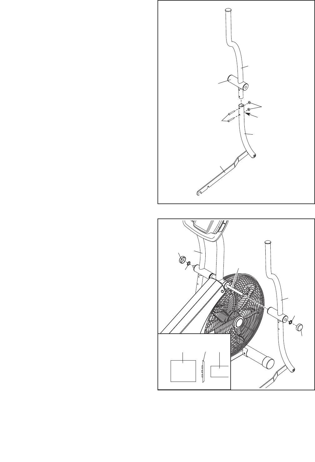
10. Slide the Left and Right Handlebars (7, 9) onto
the Handlebar Axle (33). Make sure that the
Handlebars are on the correct sides.
Using the included pedal tool, tap a Push Nut
(78) onto each end of the Handlebar Axle (33).
Make sure that the Push Nuts are turned as
shown in the inset drawing.
Tip: It may be helpful to have another per-
son hold a block of wood against one end of
the Handlebar Axle (33) while you tap a Push
Nut (78) onto the other end.
Then, tap a Large Axle Cap (49) onto each end
of the Handlebar Axle (33). 49
49
78
78
33
9
78
Pedal Tool 33
9. Identify the Right Handlebar (9) and the Right
Handlebar Base (10), which are marked with
“Right” stickers. Orient these parts so that the
wide side of the tube on the Right Handlebar
and the Right Link Arm (16) are on the same
side.
Attach the Right Handlebar (9) to the Right
Handlebar Base (10) with two M6 x 38mm
Button Bolts (57) and two M6 Locknuts (56).
Make sure that the Locknuts are in the
hexagonal holes.
Attach the Left Handlebar (not shown) to the
Left Handlebar Base (not shown) in the
same way.
9
10
16
57
56
Wide Side
of the Tube
Hexagonal
Holes
9
7
10
12. Make sure that all parts are properly tightened before you use the exercise cycle. Note: After assembly is
completed, some extra parts may be left over. Place a mat beneath the exercise cycle to protect the floor.
11
23
26
68
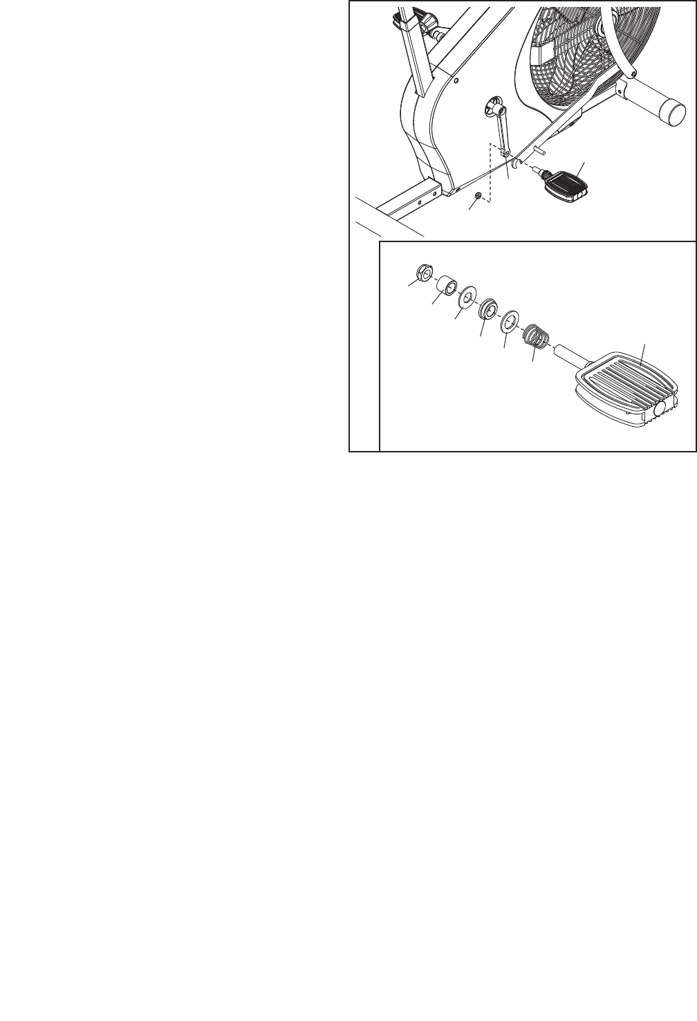
11. Remove the 1/2" Pedal Nut (68) from the shaft
of one of the Pedals (23). See the inset draw-
ing. Make sure that there is a Pedal Spring
(42), a Blue Washer (71), a Pedal Bushing (43),
a Black Pedal Washer (79), and a Pedal Spacer
(44) on the shaft of the Pedal. In addition, make
sure that the Pedal Bushing (43) is oriented as
shown.
Firmly tighten the shaft of the Pedal (23) clock-
wise into the right Crank Arm (26). Then, tighten
the 1/2" Pedal Nut (68) onto the shaft.
Attach the other Pedal (not shown) in the
same way.
23
68
42
71
43
79
44
11
HOW TO USE THE EXERCISE CYCLE
HANDLEBAR OPERATION
You can use the handlebars in the dual-action mode,
for upper- and lower-body exercise, or in the station-
ary mode, for pedaling exercise only.
Dual-action Mode
To convert the handlebars to the dual-action mode,
the link arms must be connected to the pedals.
First, lift the link arms off the lock rods.
Next, pull the link arms outward against the tops of the
blue washers, while pulling against the bottoms of the
blue washers with your fingers as shown. Be careful
not to pinch your fingers. Next, slide the link arms
onto the pedal bushings. Move the link arms upward
and downward slightly to make sure that they are fully
seated on the pedal bushings. CAUTION: Make sure
that the link arms are fully seated on the pedal
bushings. If the link arms are not on the pedal
bushings, they may slip off during use, resulting
in injury to the user.
Stationary Mode
To convert the handlebars to the stationary mode, the
link arms must be disconnected from the pedals. Pull
the link arms outward against the blue washers until
the link arms are free of the pedal bushings (see
drawing 2 at the left). Be careful not to pinch your
fingers. Next, lift the link arms off the pedals, and clip
them onto the lock rods (see drawing 1 at the left).
HOW TO ADJUST THE SEAT
For effective exercise, the seat must be at the proper
height. As you pedal, there should be a slight bend in
your knees when the pedals are in the lowest position.
To adjust the seat,
first turn the seat
knob counterclock-
wise two or three
turns to loosen it.
Next, pull the seat
knob, raise or lower
the seat post, and
then release the
seat knob. Move
the seat post
upward and down-
ward slightly to
make sure that the
pin on the seat
knob is engaged in one of the adjustment holes in
the seat post. Then, tighten the seat knob.
CAUTION: Make sure that the pin on the seat knob
is inserted into one of the adjustment holes in the
seat post. Do not rest the seat post on top of the
pin on the seat knob.
Lock
Rod
1
Link
Arm
Link Arm
Blue
Washer
Pedal
Bushing
2
Seat
Post
Seat
Seat
Knob
12
HOW TO USE THE CONSOLE
Before using the console, make sure that batteries are
installed (see assembly step 7 on page 8). If there is a
sheet of clear plastic on the display, remove the plastic.
Follow the steps below to operate the console.
1. Turn on the console.
To turn on the console, press the On/Reset button
or begin pedaling. The entire display will light for a
moment; the console will then be ready for use.
2. Follow your progress with the display.
The lower left display
can show the elapsed
time and the distance
(in miles or kilometers)
that you have pedaled.
The lower right
display can show your
pedaling speed (in
miles or kilometers per
hour) and the approxi-
mate number of
calories you have burned. When you use the
handgrip pulse sensor, the lower right display will
also show your heart rate (see step 3 on page 13).
The upper display is
the priority display.
The priority display can
show the elapsed time,
the distance that you
have pedaled, your
pedaling speed, or the approximate number of
calories you have burned. Press the Priority
Display button repeatedly until the priority display
shows the information that you are most interested
in viewing. Note: While information is shown in the
priority display, the same information will not be
shown in the lower left or lower right display.
CONSOLE DIAGRAM
13
The right display will show a
track that represents 1/4 mile
(400 meters). As you exercise,
indicators will appear in succes-
sion around the track until the
entire track appears. The track
will then disappear and the indi-
cators will again begin to appear
in succession.
To reset the displays, press the On/Reset button.
To pause the console, stop pedaling. When the
console is paused, the time will flash in the dis-
play. To continue your workout, simply resume
pedaling.
Note: The console
can show speed and
distance in either
miles or kilometers.
To select the unit of
measurement, hold
down the Priority Display button for several sec-
onds. An “E” for English miles or an “M” for metric
kilometers will appear in the lower left display. To
change the unit of measurement, hold down the
On/Reset button for several seconds until the
desired unit of measurement appears in the dis-
play. Then, press the Priority Display button to
save your selection.
3. Measure your heart rate if desired.
If there are sheets of
clear plastic on the
metal contacts on
the handgrip pulse
sensor, remove the
plastic. In addition,
make sure that your
hands are clean. To
measure your heart
rate, hold the handgrip
pulse sensor with your
palms resting against the metal contacts. Avoid
moving your hands or gripping the contacts
tightly.
When your pulse is
detected, the heart-
shaped indicator in the
lower right display will
flash and one or two
dashes will appear.
After a moment, your heart rate will be shown in
the display. For the most accurate heart rate read-
ing, continue to hold the contacts for about 15
seconds.
If your heart rate is not shown, make sure that
your hands are positioned as described. Be care-
ful not to move your hands excessively or to
squeeze the metal contacts tightly. For optimal
performance, clean the metal contacts using a soft
cloth; never use alcohol, abrasives, or chemi-
cals to clean the contacts.
4. When you are finished exercising, the console
will turn off automatically.
If the pedals do not move for a few seconds, the
time will flash in the display and the console will
pause. If the pedals do not move for a few min-
utes, the console will turn off and the display will
be reset.
Contacts
14
MAINTENANCE AND TROUBLESHOOTING
Inspect and tighten all parts of the exercise cycle reg-
ularly. To clean the exercise cycle, use a damp cloth
and a small amount of mild detergent; never use
abrasives or solvents to clean the exercise cycle.
To avoid damaging the console, keep liquid away
from the console.
CONSOLE TROUBLESHOOTING
If the console does not function properly, the batter-
ies should be replaced. See assembly step 7 on
page 8 for battery installation instructions.
ADJUSTING THE BELT
The exercise cycle features a precision belt that must
be kept properly adjusted. If the belt is too tight, the
bearings may be damaged; if the belt is too loose,
the fan may be damaged. If the belt causes excessive
noise or slips as you pedal, follow the steps below.
Carefully remove the four Guard Clips (76), the left
Guard Fastener (35), and the Left Guard (13). See the
inset drawing. Press down on the Belt (22). There
should be no more than 3/4 in. (2 cm), and no less
than 1/4 in. (0.6 cm), of vertical movement in the
center of the Belt.
If the Belt (22) needs to be adjusted, first loosen the
right Guard Fastener (not shown). To tighten the Belt,
turn the M6 Nuts (53) clockwise; to loosen the Belt,
turn the M6 Nuts counterclockwise.
See the drawing at the left. Make sure that the Fan
(5) is straight, and then reattach the Left Guard (13),
tighten the Guard Fasteners (35), and reattach the
Guard Clips (76).
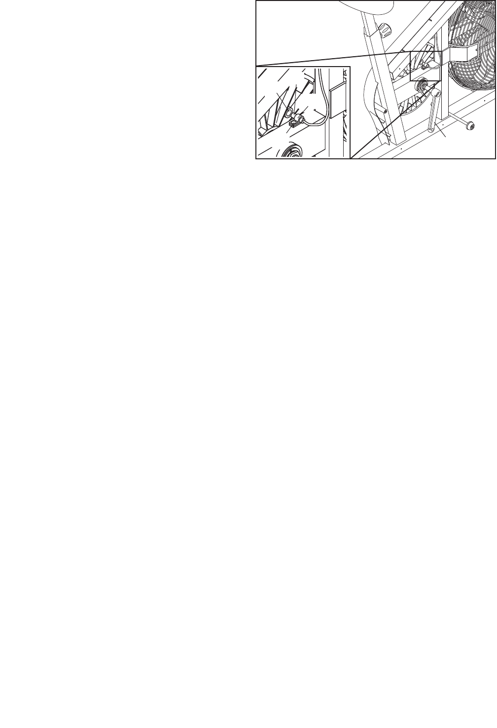
ADJUSTING THE REED SWITCH
If the console does not display correct feedback, the
reed switch should be adjusted. To adjust the reed
switch, the Right Shield (18) must be moved. Remove
the four M4 x 25mm Screws (69) from the Right
Shield. Lift the Right Link Arm (16) off the pedal or the
lock rod and move it clear of the Right Shield. Then,
pull the top of the Right Shield away from the Left
Shield (17).
69
18
17
69
Lock Rod
16
69
35
76
76
13
53
22
76
22
5
15
Next, locate the Reed Switch (31). Turn the Crank Arm
(26) until the Magnet (48) is aligned with the Reed
Switch. Loosen, but do not remove, the M4 x 16mm
Screw (27). Then, slide the Reed Switch slightly closer
to or away from the Magnet and retighten the Screw.
Turn the Crank for a moment. Repeat until the console
displays correct feedback.
When the Reed Switch (31) is correctly adjusted, reat-
tach the Right Shield (not shown).
26
31
48
32
27
16
These guidelines will help you to plan your exercise
program. For detailed exercise information, obtain a
reputable book or consult your physician. Remember,
proper nutrition and adequate rest are essential for
successful results.
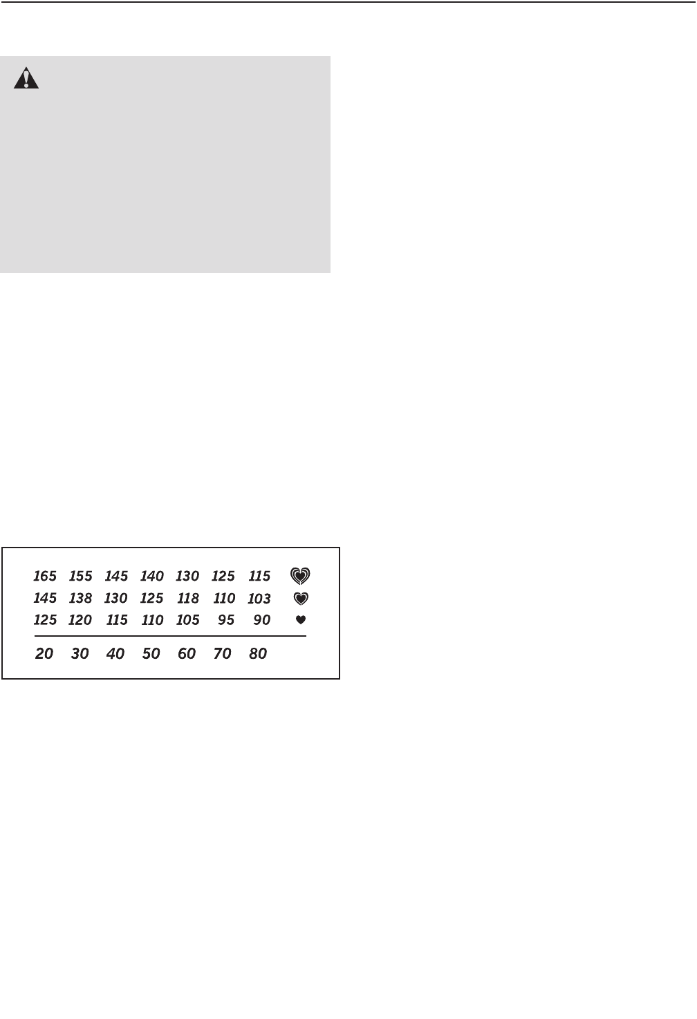
EXERCISE INTENSITY
Whether your goal is to burn fat or to strengthen your
cardiovascular system, exercising at the proper inten-
sity is the key to achieving results. You can use your
heart rate as a guide to find the proper intensity level.
The chart below shows recommended heart rates for
fat burning and aerobic exercise.
To find the proper intensity level, find your age at the
bottom of the chart (ages are rounded off to the near-
est ten years). The three numbers listed above your
age define your “training zone.” The lowest number is
the heart rate for fat burning, the middle number is the
heart rate for maximum fat burning, and the highest
number is the heart rate for aerobic exercise.
Burning Fat—To burn fat effectively, you must exer-
cise at a low intensity level for a sustained period of
time. During the first few minutes of exercise, your
body uses carbohydrate calories for energy. Only after
the first few minutes of exercise does your body begin
to use stored fat calories for energy. If your goal is to
burn fat, adjust the intensity of your exercise until your
heart rate is near the lowest number in your training
zone. For maximum fat burning, exercise with your
heart rate near the middle number in your training
zone.
Aerobic Exercise—If your goal is to strengthen your
cardiovascular system, you must perform aerobic
exercise, which is activity that requires large amounts
of oxygen for prolonged periods of time. For aerobic
exercise, adjust the intensity of your exercise until
your heart rate is near the highest number in your
training zone.
WORKOUT GUIDELINES
Warming Up—Start with 5 to 10 minutes of stretching
and light exercise. A warm-up increases your body
temperature, heart rate, and circulation in preparation
for exercise.
Training Zone Exercise—Exercise for 20 to 30 min-
utes with your heart rate in your training zone. (During
the first few weeks of your exercise program, do not
keep your heart rate in your training zone for longer
than 20 minutes.) Breathe regularly and deeply as you
exercise–never hold your breath.
Cooling Down—Finish with 5 to 10 minutes of
stretching. Stretching increases the flexibility of your
muscles and helps to prevent post-exercise problems.
EXERCISE FREQUENCY
To maintain or improve your condition, complete three
workouts each week, with at least one day of rest
between workouts. After a few months of regular exer-
cise, you may complete up to five workouts each
week, if desired. Remember, the key to success is to
make exercise a regular and enjoyable part of your
everyday life.
EXERCISE GUIDELINES
WARNING: Before beginning
this or any exercise program, consult your
physician. This is especially important for
persons over age 35 or persons with pre-
existing health problems.
The pulse sensor is not a medical device.
Various factors may affect the accuracy of
heart rate readings. The pulse sensor is
intended only as an exercise aid in determin-
ing heart rate trends in general.
17
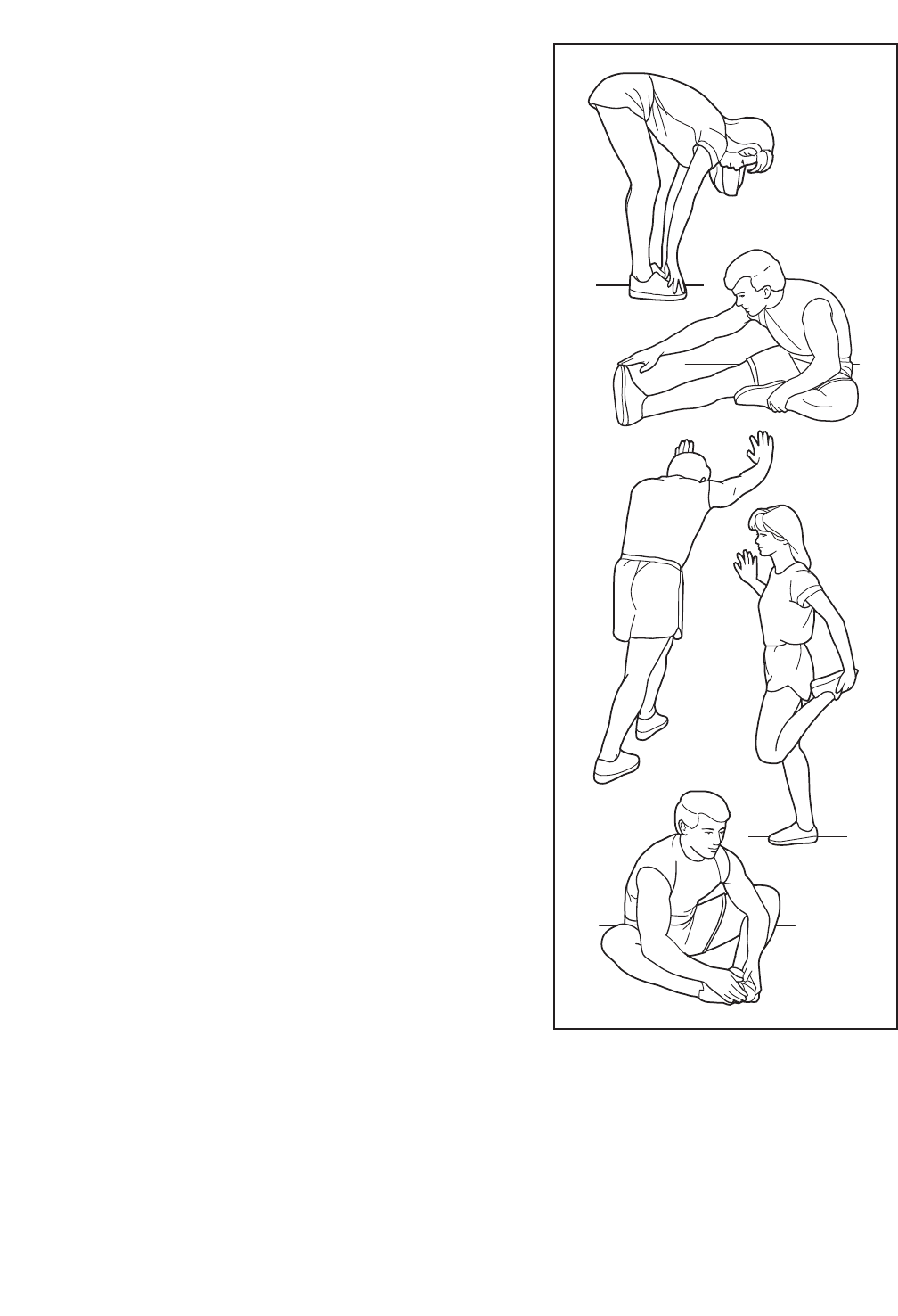
SUGGESTED STRETCHES
The correct form for several basic stretches is shown at the
right. Move slowly as you stretch—never bounce.
1. Toe Touch Stretch
Stand with your knees bent slightly and slowly bend forward
from your hips. Allow your back and shoulders to relax as you
reach down toward your toes as far as possible. Hold for 15
counts, then relax. Repeat 3 times. Stretches: Hamstrings, back
of knees and back.
2. Hamstring Stretch
Sit with one leg extended. Bring the sole of the opposite foot
toward you and rest it against the inner thigh of your extended
leg. Reach toward your toes as far as possible. Hold for 15
counts, then relax. Repeat 3 times for each leg. Stretches:
Hamstrings, lower back and groin.
3. Calf/Achilles Stretch
With one leg in front of the other, reach forward and place your
hands against a wall. Keep your back leg straight and your back
foot flat on the floor. Bend your front leg, lean forward and move
your hips toward the wall. Hold for 15 counts, then relax. Repeat
3 times for each leg. To cause further stretching of the achilles
tendons, bend your back leg as well. Stretches: Calves, achilles
tendons and ankles.
4. Quadriceps Stretch
With one hand against a wall for balance, reach back and grasp
one foot with your other hand. Bring your heel as close to your
buttocks as possible. Hold for 15 counts, then relax. Repeat 3
times for each leg. Stretches: Quadriceps and hip muscles.
5. Inner Thigh Stretch
Sit with the soles of your feet together and your knees outward.
Pull your feet toward your groin area as far as possible. Hold for
15 counts, then relax. Repeat 3 times. Stretches: Quadriceps
and hip muscles.
1
2
3
4
5

18
11Frame
21Upright
31Console
46 M10 x 22mm Patch Screw
51Fan
61Seat Post
71Left Handlebar
81Left Handlebar Base
91Right Handlebar
10 1 Right Handlebar Base
11 2 Foam Grip
12 2 Handlebar Cap
13 1 Left Guard
14 1 Right Guard
15 1 Left Link Arm
16 1 Right Link Arm
17 1 Left Shield
18 1 Right Shield
19 1 Front Stabilizer
20 1 Seat
21 4 Stabilizer Cap
22 1 Belt
23 2 Pedal
24 2 Handlebar Base Cap
25 1 Pulley
26 2 Crank Arm
27 1 M4 x 16mm Flange Head Screw
28 1 Bearing Assembly
29 1 Seat Knob
30 2 Guard Bracket
31 1 Reed Switch/Wire
32 1 Clamp
33 1 Handlebar Axle
34 6 Handlebar Bushing
35 2 Guard Fastener
36 1 Fan Axle
37 2 Fan Bearing
38 2 Adjustment Bracket
39 1 Extension Wire
40 1 Idler Arm
41 2 Crank Cover
42 2 Pedal Spring
43 2 Pedal Bushing
44 2 Pedal Spacer
45 2 Link Arm Bushing
46 1 Seat Guide
47 1 Seat Post Bushing
48 2 Magnet
49 2 Large Axle Cap
50 2 Small Axle Cap
51 1 Fan Washer
52 2 Eyebolt
53 2 M6 Nut
54 9 M10 Split Washer
55 3 M10 x 17mm Patch Screw
56 4 M6 Locknut
57 4 M6 x 38mm Button Bolt
58 2 M8 x 74mm Button Bolt
59 1 M10 x 20mm Flat Head Bolt
60 1 Rear Stabilizer
61 1 M4 x 16mm Bright Screw
62 4 M4 x 16mm Round Head Screw
63 1 Idler Arm Washer
64 3 M10 Locknut
65 2 M10 x 75mm Carriage Bolt
66 10 M8 Locknut
67 2 Flange Screw
68 2 1/2" Pedal Nut
69 9 M4 x 25mm Screw
70 1 M4 x 5mm Patch Screw
71 2 Blue Washer
72 8 M8 Split Washer
73 4 M8 Flat Washer
74 1 Fan Spacer
75 1 Idler Spring
76 4 Guard Clip
77 5 M4 x 16mm Screw
78 2 Push Nut
79 2 Black Pedal Washer
80 1 Ground Wire
81 4 M8 x 20mm Button Bolt
82 1 Crank
83 2 Snap Ring
*–Assembly Tool
*–Userʼs Manual
PART LIST—Model No. 831.21822.1 R1109A
Key No. Qty. Description Key No. Qty. Description
Note: Specifications are subject to change without notice. For information about ordering replacement parts, see
the back cover of this manual. *These parts are not illustrated. If a part is missing, call 1-888-533-1333.
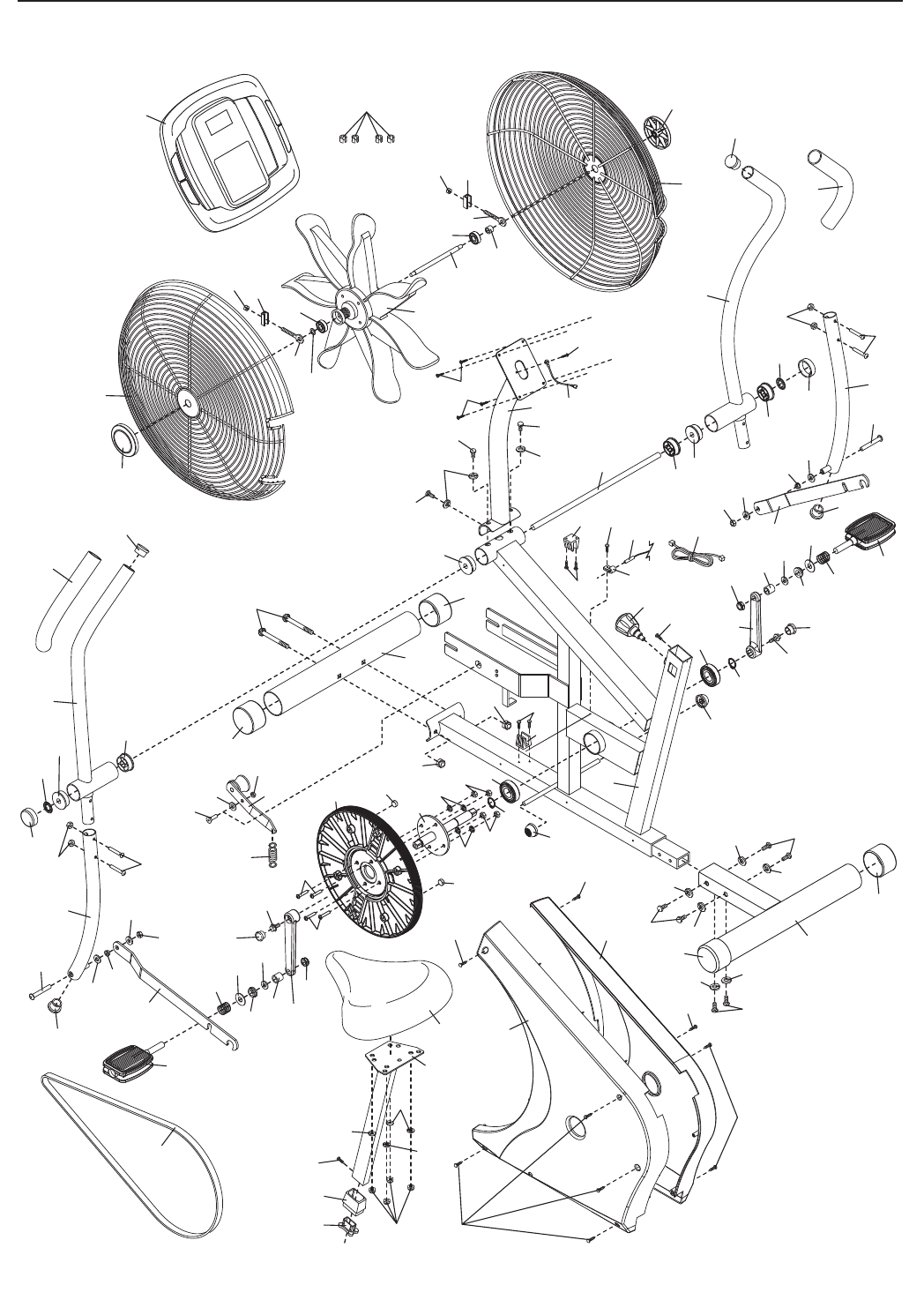
19
EXPLODED DRAWING—Model No. 831.21822.1 R1109A
1
2
3
5
6
7
8
9
10
11
11
12
12
14
13
15
16
17
18
19
20
21
21
22
23
23
25
26
26
28
82
29
30 31
32
30
33 3434
34
34
34
34
35
35
36
37
37
38
38
39
40
41
41
42
43 44
42
43
44
45
45
46
47
48
49
78
50
50
74
51
52
53
52
53
54
54
55
55
56
56 57
57
58
58
59
64
66
66
64
64
65
66
67
68
67
68
62
27
69
69
69
69
77
62
70
71
71
63
73
73
75
78
49
55
76
79
73
79
72
72
77
24
24
73
72
69
21
21
4
54 54
54
4
54
54 4
60
61
54
48
80
81
81
66
66 28
72
72
83
83

Part No. 292682 R1109A Printed in China © 2009 ICON IP, Inc.
Your Home
For repair—in your home—of all major brand appliances, lawn and garden equipment,
or heating and cooling systems, no matter who made it, no matter who sold it!
For the replacement parts, accessories, and user’s manuals that you need to do-it-yourself.
For Sears professional installation of home appliances
and items like garage door openers and water heaters.
1-800-4-MY-HOME®(1-800-469-4663)
Call anytime, day or night (U.S.A. and Canada)
www.sears.com www.sears.ca
Our Home
For repair of carry-in items like vacuums, lawn equipment,
and electronics, call or go on-line for the location of your nearest
Sears Parts & Repair Center.
1-800-488-1222 Call anytime, day or night (U.S.A. only)
www.sears.com
To purchase a protection agreement (U.S.A.)
or maintenance agreement (Canada) on a product serviced by Sears:
1-800-827-6655 (U.S.A.) 1-800-361-6665 (Canada)
Para pedir servicio de reparación a domicilio, y para ordenar piezas:
1-888-SU-HOGAR®(1-888-784-6427)
Get it fixed, at your home or ours!
®Registered Trademark / TM Trademark / SM Service Mark of Sears Brands, LLC
®Marca Registrada / TM Marca de Fábrica / SM Marca de Servicio de Sears Brands, LLC
90 DAY FULL WARRANTY
If this Sears bike exerciser fails due to a defect in material or workmanship within 90 days of the date of
purchase, call 1-800-4-MY-HOME®(1-800-469-4663) to arrange for free repair (or replacement if repair
proves impossible). The frame is warranted for a period of 5 years from the date of purchase.
This warranty does not apply when the bike exerciser is used commercially or for rental purposes.
This warranty gives you specific legal rights, and you may also have other rights which vary from state
to state.
Sears, Roebuck and Co., Hoffman Estates, IL 60179
