Proform Petl409061 480 Cx Treadmill Users Manual 294241 205863
2015-04-13
: Proform Proform-Petl409061-480-Cx-Treadmill-Users-Manual-698492 proform-petl409061-480-cx-treadmill-users-manual-698492 proform pdf
Open the PDF directly: View PDF ![]() .
.
Page Count: 36
USER'S MANUAL
Model No. PETL40906.1
Serial No.
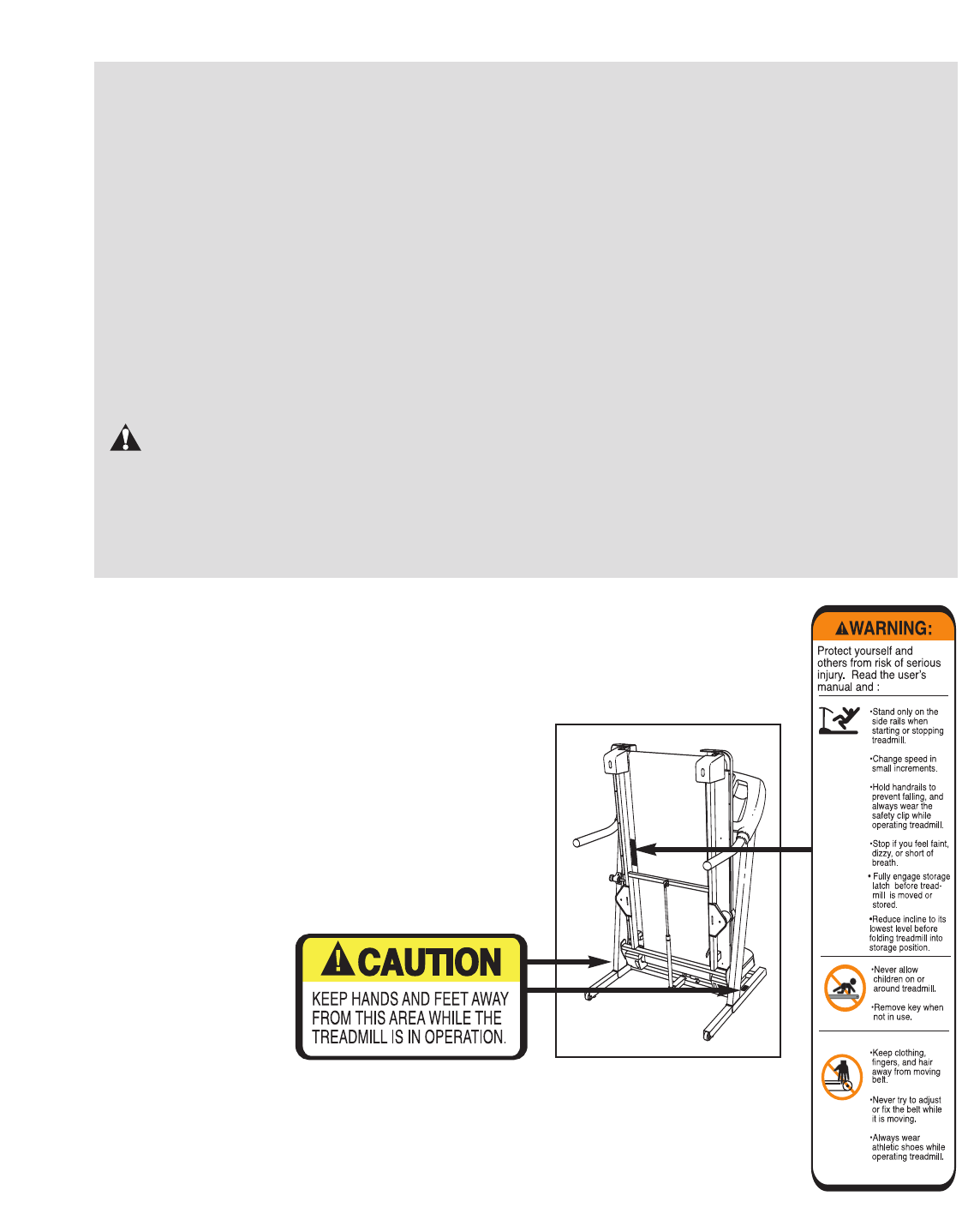
CAUTION
Read all precautions and instruc-
tions in this manual before using
this equipment. Save this manual
for future reference.
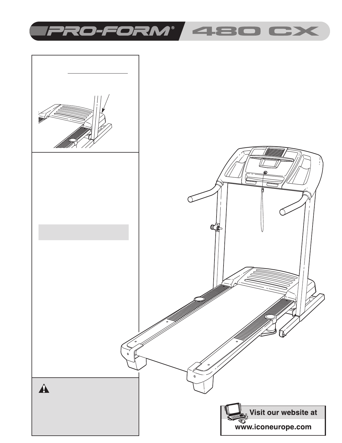
Serial Number
Decal
QUESTIONS?
As a manufacturer, we are com-
mitted to providing complete
customer satisfaction. If you
have questions, or if there are
missing or damaged parts,
please call:
or write:
ICON Health & Fitness, Ltd.
Customer Service Department
Unit 4
Revie Road Industrial Estate
Revie Road
Beeston
Leeds, LS118JG
UK
email: csuk@iconeurope.com
08457 089 009

TABLE OF CONTENTS
IMPORTANT PRECAUTIONS . . . . . . . . . . . . . . . . . . . . . . . . . . . . . . . . . . . . . . . . . . . . . . . . . . . . . . . . . . . . . . . .3
BEFORE YOU BEGIN . . . . . . . . . . . . . . . . . . . . . . . . . . . . . . . . . . . . . . . . . . . . . . . . . . . . . . . . . . . . . . . . . . . . . .5
ASSEMBLY . . . . . . . . . . . . . . . . . . . . . . . . . . . . . . . . . . . . . . . . . . . . . . . . . . . . . . . . . . . . . . . . . . . . . . . . . . . . . . .6
OPERATION AND ADJUSTMENT . . . . . . . . . . . . . . . . . . . . . . . . . . . . . . . . . . . . . . . . . . . . . . . . . . . . . . . . . . . .11
HOW TO FOLD AND MOVE THE TREADMILL . . . . . . . . . . . . . . . . . . . . . . . . . . . . . . . . . . . . . . . . . . . . . . . . . .24
TROUBLESHOOTING . . . . . . . . . . . . . . . . . . . . . . . . . . . . . . . . . . . . . . . . . . . . . . . . . . . . . . . . . . . . . . . . . . . . .26
CONDITIONING GUIDELINES . . . . . . . . . . . . . . . . . . . . . . . . . . . . . . . . . . . . . . . . . . . . . . . . . . . . . . . . . . . . . . .28
PART LIST . . . . . . . . . . . . . . . . . . . . . . . . . . . . . . . . . . . . . . . . . . . . . . . . . . . . . . . . . . . . . . . . . . . . . . . . . . . . . .31
EXPLODED DRAWING . . . . . . . . . . . . . . . . . . . . . . . . . . . . . . . . . . . . . . . . . . . . . . . . . . . . . . . . . . . . . . . . . . . .32
ORDERING REPLACEMENT PARTS . . . . . . . . . . . . . . . . . . . . . . . . . . . . . . . . . . . . . . . . . . . . . . . . . .Back Cover
2
PROFORM is a registered trademark of ICON IP, Inc.

1. It is the responsibility of the owner to ensure
that all users of this treadmill are adequately
informed of all warnings and precautions.
2. Use the treadmill only as described.
3. Place the treadmill on a level surface, with at
least 2.5 m (8 ft.) of clearance behind it and
0.5 m (2 ft.) on each side. Do not place the
treadmill on a surface that blocks any air
openings. To protect the floor or carpet from
damage, place a mat under the treadmill.
4. Keep the treadmill indoors, away from mois-
ture and dust. Do not put the treadmill in a
garage or covered patio, or near water.
5. Do not operate the treadmill where aerosol
products are used or where oxygen is being
administered.
6. Keep children under the age of 12 and pets
away from the treadmill at all times.
7. The treadmill should be used only by persons
weighing 136 kg (300 lbs.) or less.
8. Never allow more than one person on the
treadmill at a time.
9. Wear appropriate exercise clothes when
using the treadmill. Do not wear loose clothes
that could become caught in the treadmill.
Athletic support clothes are recommended for
both men and women.
Always wear athletic
shoes; never use the treadmill with bare feet,
wearing only stockings, or in sandals.
10. When connecting the power cord (see page
11), plug the power cord into an earthed cir-
cuit. No other appliance should be on the
same circuit. When replacing the fuse, an
ASTA approved BS1362 type should be fitted
to the fuse carrier. A 13 amp fuse should be
used.
11. Keep the power cord away from heated sur-
faces.
12. Never move the walking belt while the power
is turned off. Do not operate the treadmill if
the power cord or plug is damaged, or if the
treadmill is not working properly. (See TROU-
BLESHOOTING on page 26 if the treadmill is
not working properly.)
13. Read, understand, and test the emergency
stop procedure before using the treadmill (see
HOW TO TURN ON THE POWER on page 13).
14. Never start the treadmill while you are stand-
ing on the walking belt. Always hold the
handrails while using the treadmill.
15. The treadmill is capable of high speeds.
Adjust the speed in small increments to avoid
sudden jumps in speed.
16. The pulse sensor is not a medical device.
Various factors, including your movement,
may affect the accuracy of heart rate readings.
The sensor is intended only as an exercise aid
in determining heart rate trends in general.
17. Never leave the treadmill unattended while it
is running. Always remove the key and unplug
the power cord when the treadmill is not in
use.
18. Do not attempt to raise, lower, or move the
treadmill until it is properly assembled. (See
ASSEMBLY on page 6, and HOW TO FOLD
AND MOVE THE TREADMILL on page 24.)
You must be able to safely lift 20 kg (45 lbs.) to
raise, lower, or move the treadmill.
19. When folding or moving the treadmill, make
sure that the storage latch is fully engaged.
20. When using iFIT.com programs, an electronic
“chirping” sound will alert you when the
speed and/or incline of the treadmill is about
to change. Always listen for the “chirp” and
be prepared for speed and/or incline changes.
In some instances, the speed and/or incline
may change before the personal trainer de-
scribes the change.
WARNING: Toreduce the risk of burns, fire, electric shock, or injury to persons, read the
following important precautions and information before operating the treadmill.
IMPORTANT PRECAUTIONS
3
21. When using iFIT.com programs, you can
manually override the speed and incline set-
tings by pressing the speed and incline but-
tons. However, when the next “chirp” is
heard, the speed and/or incline will change
to the next settings of the CD or video pro-
gram.
22. Always remove iFIT.com CDs and videos
from your CD player or VCR and disconnect
your MP3 player when you are not using
them.
23. Inspect and properly tighten all parts of the
treadmill regularly.
24. Never insert any object into any opening.
25. DANGER: Always unplug the power
cord immediately after use, before cleaning
the treadmill, and before performing the
maintenance and adjustment procedures de-
scribed in this manual. Never remove the
motor hood unless instructed to do so by an
authorized service representative. Servicing
other than the procedures in this manual
should be performed by an authorized ser-
vice representative only.
26. This treadmill is intended for in-home use
only. Do not use this treadmill in a commer-
cial, rental, or institutional setting.
WARNING: Before beginning this or any exercise program, consult your physician. This
is especially important for persons over the age of 35 or persons with pre-existing health problems.
Read all instructions before using. ICON assumes no responsibility for personal injury or property
damage sustained by or through the use of this product.
SAVE THESE INSTRUCTIONS
The decals shown at the right have been placed on the treadmill. If a decal is miss-
ing, or if it is illegible, call the telephone number on the front cover of this manual
and order a free replacement decal. Apply the decal in the location shown. Note:
The decals are not shown at actual size.
4
5
Thank you for selecting the new PROFORM®480 CX
treadmill. The 480 CX treadmill combines advanced
technology with innovative design to help you get the
most from your exercise in the convenience of your
home. And when you’re not exercising, the 480 CX
treadmill can be folded up, requiring less than half the
floor space of other treadmills.
For your benefit, read this manual carefully before
using the treadmill.If you have questions after read-
ing this manual, please see the front cover of this man-
ual. To help us assist you, please note the product
model number and serial number before contacting us.
The model number of the treadmill is PETL40906.1
The serial number can be found on a decal attached to
the treadmill (see the front cover of this manual for the
location).
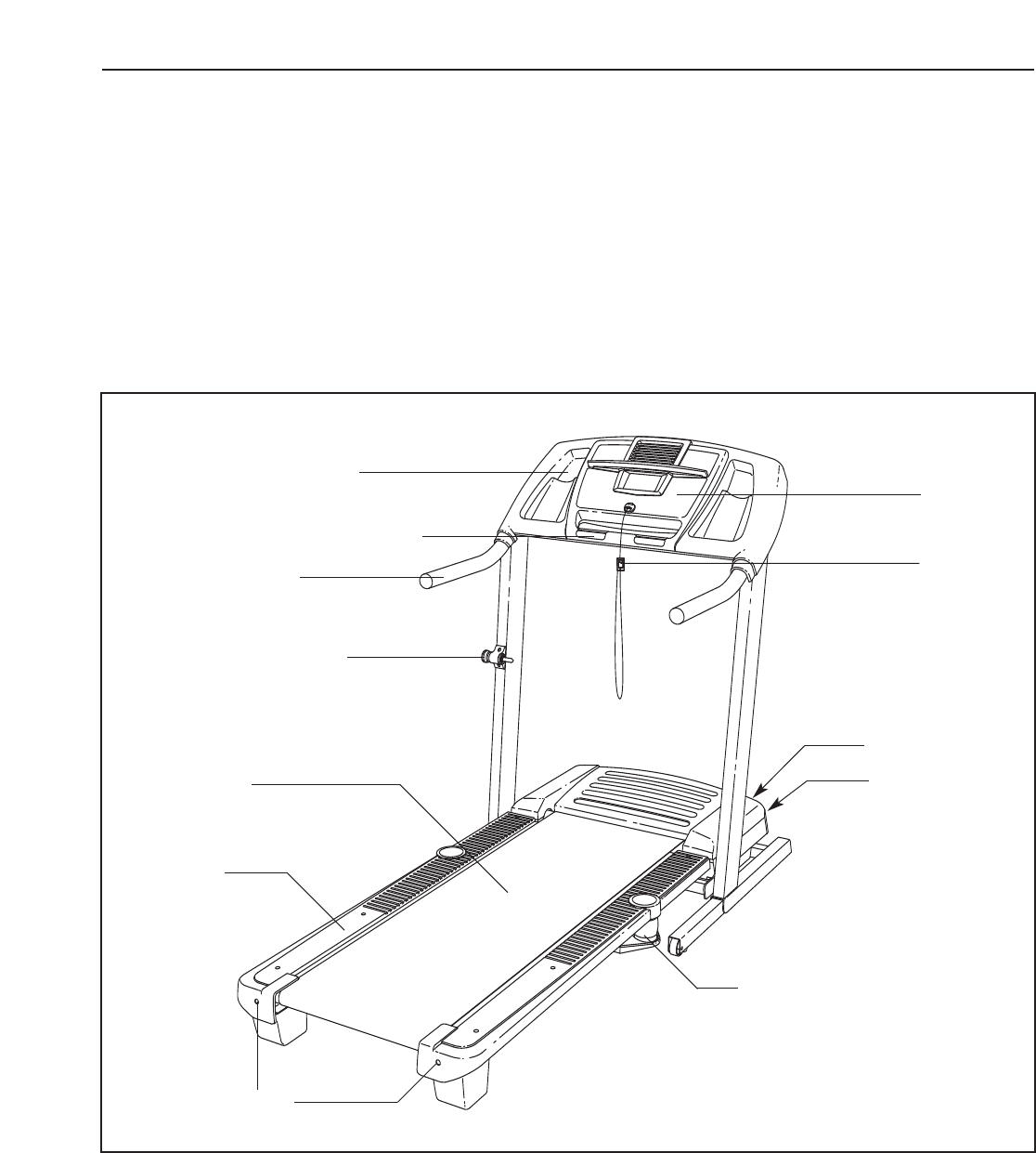
Before reading further, please familiarize yourself with
the parts that are labeled in the drawing below.
BEFORE YOU BEGIN
Handrail
Storage Latch
Key/Clip
Circuit Breaker
On/Off Switch
Walking Belt
Cushioned Walking Platform
for maximum exercise comfort
Foot Rail
RIGHT SIDE
Rear Roller
Adjustment Bolts
Console
Accessory Tray
Handgrip Pulse Sensor
BACK
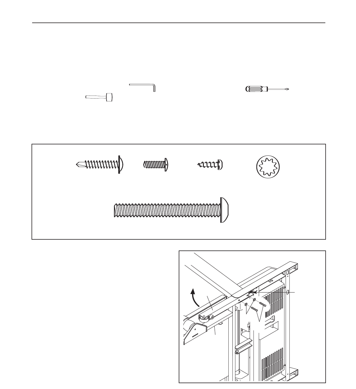
ASSEMBLY
Assembly requires two persons. Set the treadmill in a cleared area and remove all packing materials; do not
dispose of the packing materials until assembly is completed. Note: The underside of the walking belt is coated
with high-performance lubricant. During shipping, a small amount of lubricant may be transferred to the top of the
walking belt or the shipping carton. This is a normal condition and does not affect treadmill performance. If there
is lubricant on top of the walking belt, wipe off the lubricant with a soft cloth and a mild, non-abrasive cleaner.
Assembly requires the included hex keys, your own phillips screwdriver , and your
own rubber mallet .
For help identifying the assembly hardware, see the drawings below. The number in parentheses below each
drawing is the key number of the part, from the PART LIST on pages 30 and 31. The number following the paren-
theses is the quantity needed for assembly. Note: If a part is not in the parts bag, check to see if it has been
pre-assembled. To avoid damaging plastic parts, do not use power tools for assembly.
3/4” Tek Screw (58)–8
1
Sliver Ground
Screw (33)–1 1/4” Star Washer
(
H
W
Latch Screw
(XXX)–2
Handrail Bolt (20)–4
Extension Leg Bolt (64)–4
Star Washer (8)–8
Screw (3)–11
Handrail Bolt/ Extension Leg Bolt (64)–8
1” Tek Screw
(22)–4
6
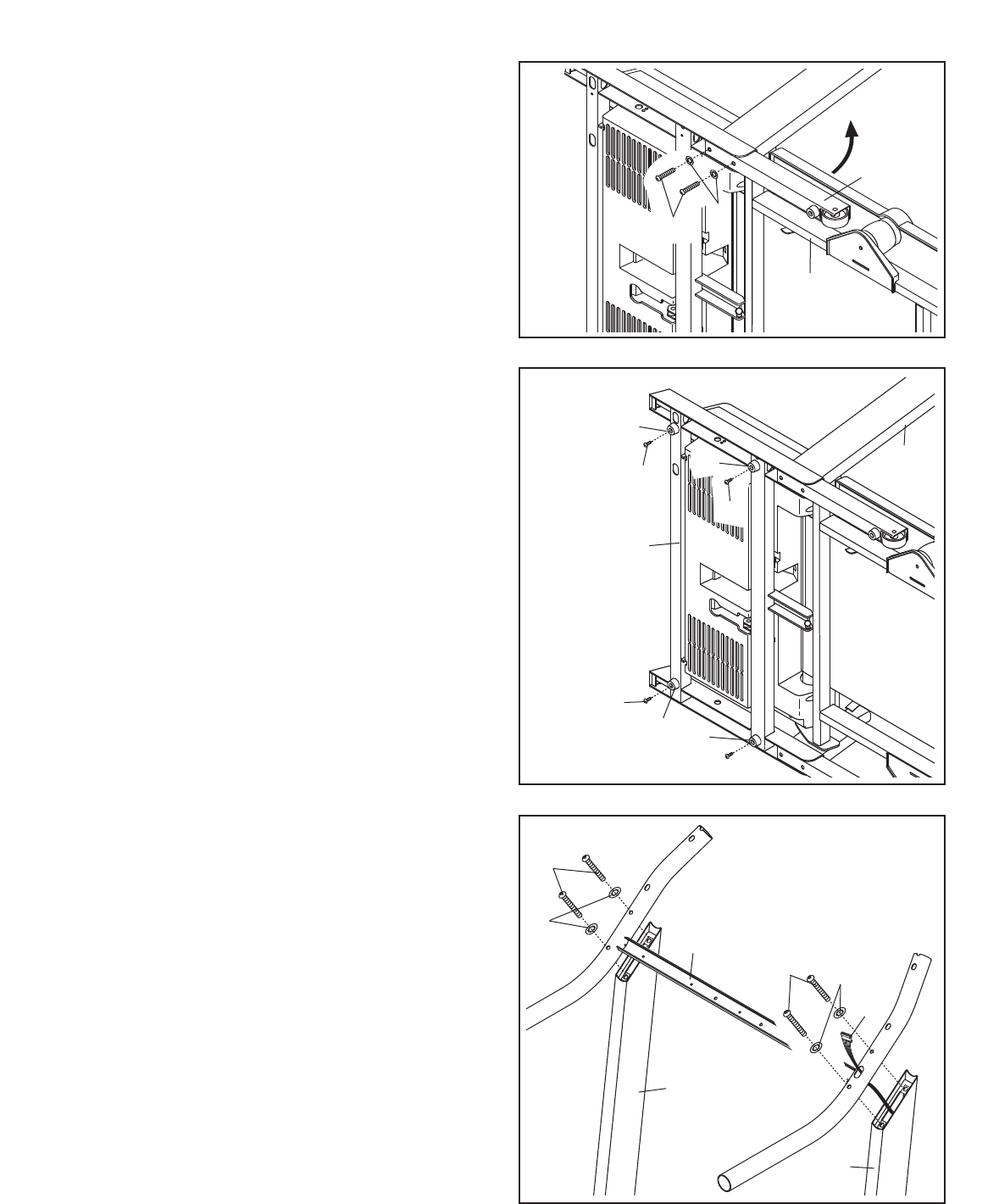
1. Make sure that the power cord is unplugged.
With the help of a second person, carefully tip
the treadmill onto its left side as shown. Partially
fold the Frame (58) so the treadmill is more sta-
ble. Do not fully fold the treadmill until it is
completely assembled.
Insert an Extension Leg (89) into the base of the
Upright (84) as shown. Note: Be careful not to
pinch the Upright Wire Harness (77) in the
base of the Upright. To fully insert the
Extension Leg, it may be necessary to tap on it
with a mallet. Next, insert two Extension Leg
Bolts (64) with Star Washers (8) into the bottom
of the Extension Leg, and firmly tighten the
Extension Leg Bolts.
8
1
58
89
64
77
7
2. With the help of a second person, carefully tip
the treadmill onto its right. Partially fold the
Frame (58) so the treadmill is more stable. Do
not fully fold the treadmill until it is com-
pletely assembled.
Insert the other Extension Leg (89) into the base
of the Uprights (84) as shown. Next, insert two
Extension Leg Bolts (64) into the bottom of the
Extension Leg, and firmly tighten the Extension
Leg Bolts.
.58
8
64
2
3. Attach four Base Pads (82) to the base of the
Uprights (84) with four 1” Tek Screws (22).
With the help of a second person, carefully raise
the treadmill so that all four Base Pads (82) are
on the floor and the Upright (84) is in a vertical
position.
84
22
22
82
82 82
84
3
89
82
22
4. Have a second person hold the Handrail (20)
near the Uprights (84). Insert the Upright Wire
Harness (77) into the hole in the bottom of the
Handrail and out of the top as shown.
Next, set the Handrail (20) on the Uprights (84).
Do not let the Upright Wire Harness (77) fall
into the right Upright.
Attach the Handrail (20) with four Handrail Bolts
(64) and four Star Washers (8); start all four
Handrail Bolts and then firmly tighten them.
84
20
8
8
77
64
84
64
4
8
5. While a second person holds the console as-
sembly near the Handrail (20), attach the ground
wire to the indicated hole in the Handrail with a
Ground Screw (33).
20
Hole
Ground
Wire
Console
Assembly
33
5
7. Set the console assembly on the Handrail (20).
Be careful to avoid pinching any of the wires.
Make sure that the ground wire (see step 5)
and the wire harness from the console as-
sembly (see step 6) are in the indicated chan-
nel.
Hand tighten five Screws (3) into the Handrail
(20) and the console assembly. Start all five
Screws, but do not tighten them yet. Do not
put Screws into the two indicated holes.
6. While the second person continues to hold the
console assembly, locate the wire harness un-
derneath the console assembly.
Connect the wire harness from the console as-
sembly to the Upright Wire Harness (77). Make
sure to connect the connectors properly (see
the inset drawing). The connectors should
slide together easily and snap into place. If
the connectors do not slide together easily and
snap into place, turn one connector and then try
again. IF THE CONNECTORS ARE NOT CON-
NECTED PROPERLY, THE CONSOLE MAY
BE DAMAGED WHEN THE POWER IS
TURNED ON. Then, insert the connectors down-
ward into the Handrail (20).
Console Assembly
33
No Screws
3
20
77
Console
Assembly
77
20
7
6
Channel
Wire
9
8. Hand tighten four additional Screws (3) into the
Handrail (20) and the console assembly. Then,
tighten all nine Screws used in step 7 and
this step; do not overtighten the Screws.
Plug in the power cord as described on page 11,
and turn on the power as described on page 13.
Note: The treadmill may automatically rise to the
maximum incline level and then return to the
minimum level.
Console Assembly
320
8
3
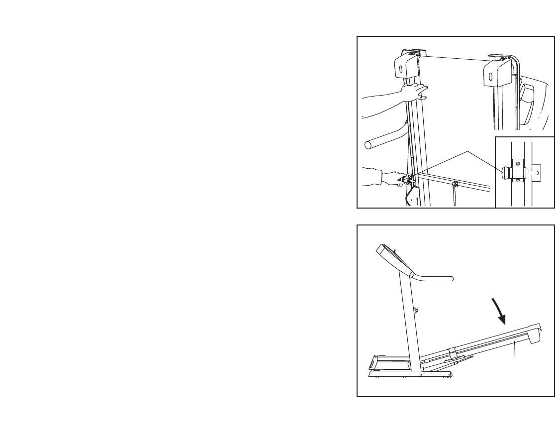
10.Place the treadmill in the storage position (see
HOW TO FOLD AND MOVE THE TREADMILL
on page 24).
Next, place the cylinder end of the Shock (92)
near the bracket on the base of the Uprights
(84).
See the two small inset drawings. Using your fin-
gernail or the end of a screwdriver, press on the
end of the Shock Pin (25) to loosen it from the
Shock (92). Next, rotate the Shock Pin and pull it
out of the Shock. Be careful to avoid losing
the Shock Pin.
See drawing 10a. Press the cylinder end of the
Shock (92) onto the ball on the bracket. Next, in-
sert the end of the Shock Pin (25) through two of
the small holes in the end of the Shock. Then,
rotate the Shock Pin until it clips onto the Shock.
92
25
92
25
10
10a
84
58
Bracket
Cylinder
Bracket
25
25
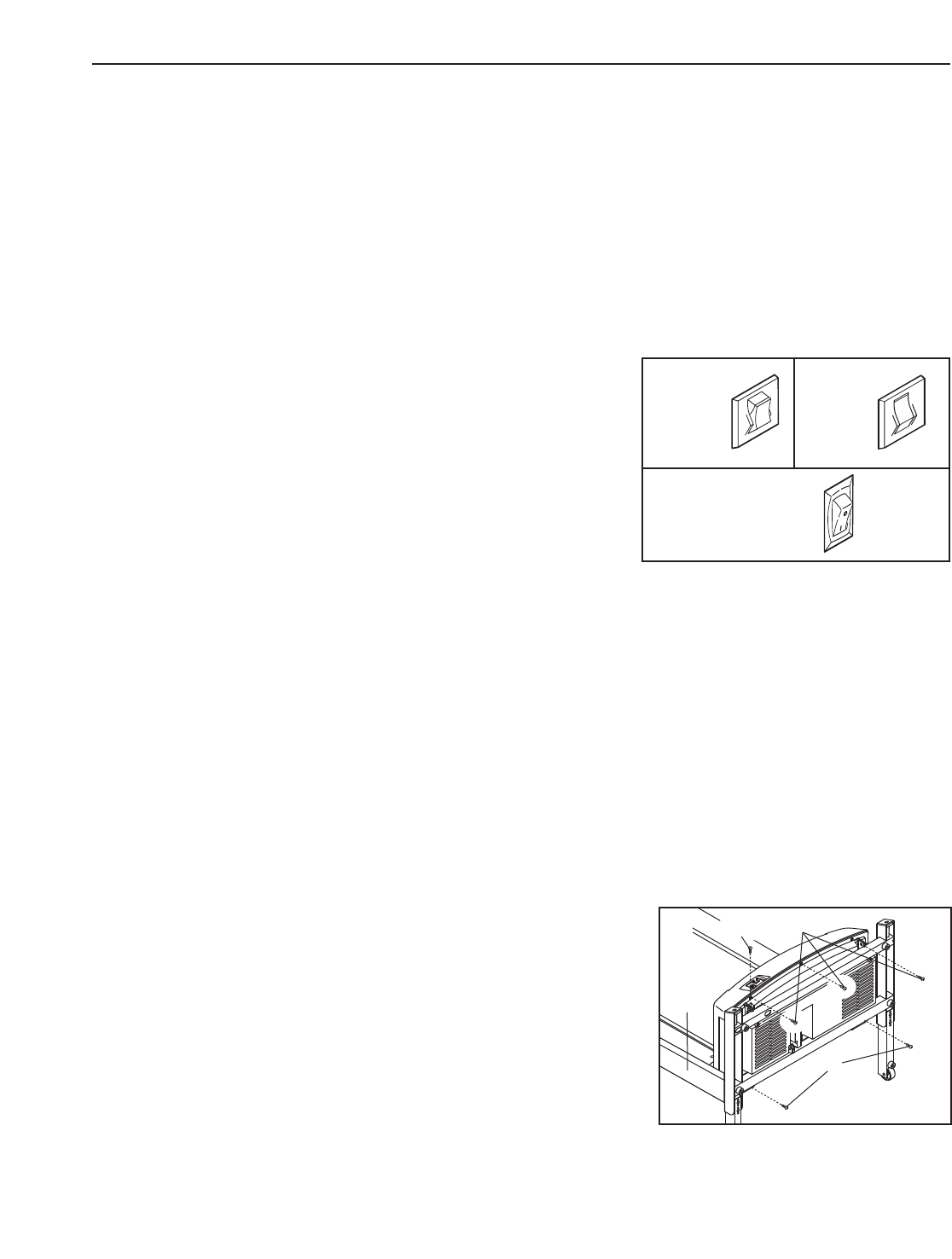
9. Attach the Latch Housing (73) to the left Upright
(84) with two Screws (3). Make sure that the
large hole in the Latch Housing is on the
side shown. Do not overtighten the Screws.
If the pin is not preassembled in the Latch
Housing (73), remove the knob from the pin.
Make sure that the collar and the spring are on
the pin as shown. Insert the pin into the Latch
Housing, and tighten the knob back onto the pin.
3
84
9
Knob
Pin
Collar
Large
Hole
Spring
73
10
12. Make sure that all parts are properly tightened before you use the treadmill. Note: Extra hardware may
be included. Keep the included hex keys in a secure place; the large hex key is used to adjust the walking belt
(see page 27). To protect the floor or carpet, place a mat under the treadmill.
1. Remove the key from the console and unplug
the power cord.
Remove the Screw (3) and the Access Door (76)
from the back of the Console Base (85).
2. Connect the wire on the receiver (A) to the indi-
cated wire extending from the Console Base
(85). Hold the receiver so the small cylinder is
oriented as shown and is facing the Console
Base. Attach the receiver to the plastic posts on
the Access Door (76) with the two included small
screws.
3. Make sure that no wires are pinched. Reattach
the Access Door (76) with the Screw (3). Discard
the other wires included with the receiver.
If you purchase the optional chest pulse sensor (see page 23), follow the steps below to install the receiver
included with the chest pulse sensor.
A
85
Small
Cylinder
3
76
Wire
Small Screws
11.Raise the Shock (92) to a vertical position.
Remove the Shock Pin (25) from the raised end
of the Shock as described in step 6. If neces-
sary, rotate the Shock to align the end of the
Shock with the ball on the bracket on the Frame
(58).
Next, press the Incline increase and decrease
buttons until the ball on the bracket is aligned
with end of the Shock (92). Then, press the end
of the Shock onto the ball. Note: It may be nec-
essary to press the end of the Shock onto the
ball while the Frame is moving.
See drawing 11a. Insert the Shock Pin (25) into
the two indicated small holes in the end of the
Shock (92). Then, rotate the Shock Pin until it
clips onto the Shock. Note: Extra Shock Pins are
included.
Press the Incline decrease button until the
treadmill is at the lowest incline level. Then,
unplug the power cord and lower the treadmill
Frame (58) to the floor.
25
92
Holes
25
92
11
11a
58 Bracket
11
THE PRE-LUBRICATED WALKING BELT
Your treadmill features a walking belt coated with high-performance lubricant. IMPORTANT: Never apply sili-
cone spray or other substances to the walking belt or the walking platform. Such substances will deterio-
rate the walking belt and cause excessive wear.
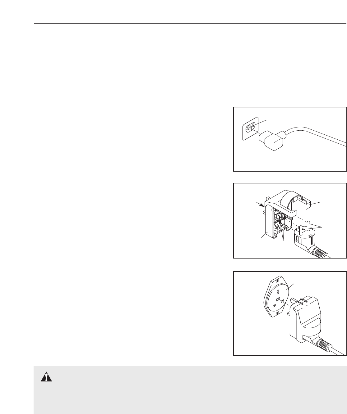
HOW TO PLUG IN THE POWER CORD
This product must be earthed. If it should malfunction or break
down, earthing provides a path of least resistance for electric cur-
rent to reduce the risk of electric shock. This product is equipped
with a power cord having an equipment-earthing conductor and an
earthing plug. Important: If the power cord is damaged, it must
be replaced with a manufacturer-recommended power cord.
See drawing 1. Plug the indicated end of the power cord into the
socket on the treadmill.
See drawing 2. Press the pins on the power cord into the metal clips
in the adapter as shown. Close the adapter cover over the end of the
power cord and tighten the screw in the adapter. Important: Make
sure that the adapter cover is secure and the screw has been
tightened before using the power cord.
See drawing 3. Plug the power cord into an appropriate outlet that is
properly installed and earthed in accordance with all local codes and
ordinances. Important: The treadmill is not compatible with
GFCI-equipped outlets.
DANGER: Improper connection of the equipment-earthing conductor can result in an in-
creased risk of electric shock. Check with a qualified electrician or serviceman if you are in doubt as
to whether the product is properly earthed. Do not modify the plug provided with the product—if it will
not fit the outlet, have a proper outlet installed by a qualified electrician.
FR/SP
IT
GR
FR/SP
IT
Socket on treadmill
Metal
Clips
1
2
Pins
Screw
Adapter
FR/SP
Outlet
3
Adapter
Cover
OPERATION AND ADJUSTMENT
12
FEATURES OF THE CONSOLE
The treadmill console offers a selection of features
designed to make your workouts more effective. When
you select the manual mode of the console, you can
change the speed and incline of the treadmill with the
touch of a button. As you exercise, the console will
display continuous exercise feedback. You can even
measure your heart rate using the handgrip pulse sen-
sor or the optional chest pulse sensor (see page 23).
The console also features ten trainer programs. Each
trainer program automatically controls the speed and
incline of the treadmill as it guides you through an ef-
fective workout. In addition, the console offers two
heart rate programs. Each heart rate program adjusts
the speed and incline of the treadmill to keep your heart
rate near a target heart rate during your workout. Note:
You must wear the optional chest pulse sensor to use
the heart rate programs.
The console also features iFIT.com interactive technol-
ogy. Having iFIT.com technology is like having a per-
sonal trainer in your home. Using a stereo audio cable,
you can connect the treadmill to your portable stereo,
home stereo, computer, or VCR and play special
iFIT.com MP3, CD, and video programs (iFIT.com MP3
programs, CDs, and videocassettes are available sepa-
rately). iFIT.com programs automatically control the
speed and incline of the treadmill as a personal trainer
guides you through every step of your workout; high-
energy music provides added motivation. To down-
load iFIT.com MP3 programs, go to www.iFIT.com.
To purchase iFIT.com CDs or videocassettes, call
the telephone number on the front cover of this
manual.
With the treadmill connected to your computer, you
can also go to www.iFIT.com and access iFIT.com
programs directly from our Web site. See
www.iFIT.com for more information.
To use the manual mode of the console, follow the
steps beginning on page 13. To use a trainer
program,see page 15. To use a heart rate program,
see page 16. To use an iFIT.com MP3, CD, or video
program,see page 17. To use an iFIT.com program
directly from our Web site,see page 19.
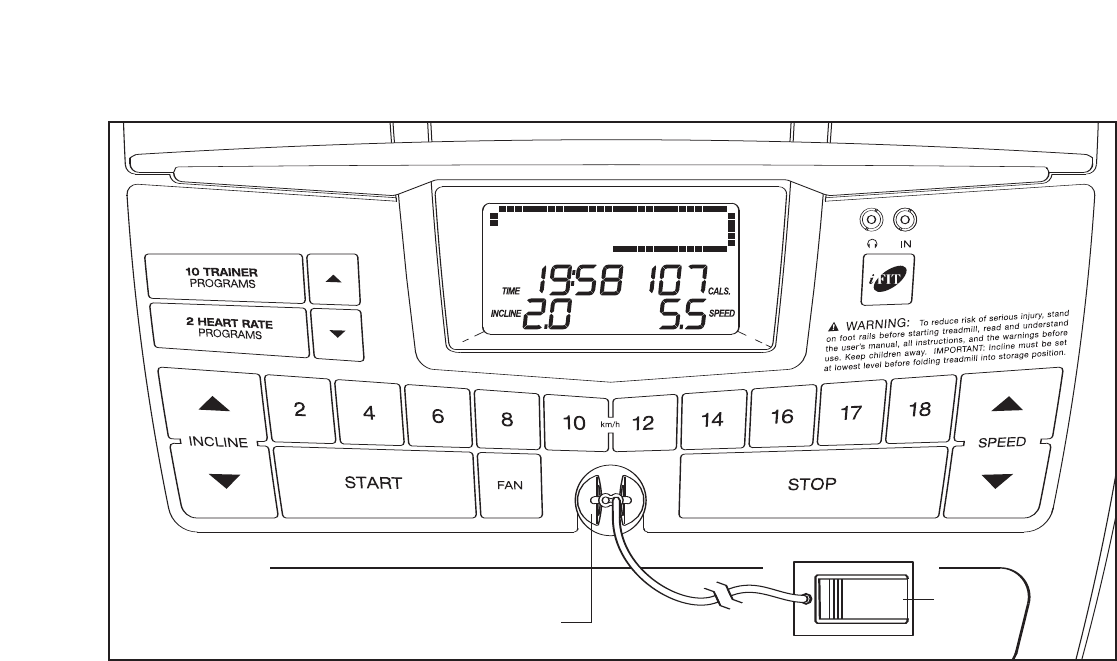
Clip
CONSOLE DIAGRAM
Note: If there is a sheet of clear plastic
on the face of the console, remove it. Key
13
HOW TO TURN ON THE POWER
Plug in the power cord
(see page 11). Next, lo-
cate the on/off switch near
the power cord. Make sure
that the switch is in the
“on” position.
Next, stand on the foot rails of the treadmill. Find the
clip attached to the key (see the drawing on page 12)
and slide the clip onto the waistband of your clothes.
Then, insert the key into the console. After a moment,
the display will light. Important: In an emergency sit-
uation, the key can be pulled from the console,
causing the walking belt to slow to a stop. Test the
clip by carefully taking a few steps backward; if the
key is not pulled from the console, adjust the posi-
tion of the clip.
HOW TO USE THE MANUAL MODE
Insert the key into the console.
See HOW TO TURN ON THE POWER above.
Select the manual mode.
When you
insert the
key, the
manual
mode will be
selected. If
you have
selected a program, reselect the manual mode by
pressing the Heart Rate Programs button repeat-
edly until a track appears in the display.
Start the walking belt.
To start the walking belt, press the Start button,
the Speed increase button, or one of the speed
buttons numbered 2 through 18.
If you press the Start button or the Speed in-
crease button, the walking belt will begin to move
at 2 km/h. As you exercise, change the speed of
the walking belt as desired by pressing the Speed
increase and decrease
buttons. Each time you
press a button, the
speed setting will
change by 0.1 km/h; if
you hold down a button,
the speed setting will change in increments of 0.5
km/h. Note: After you press the buttons, it may take
amoment for the walking belt to reach the selected
speed setting.
If you press one of the numbered speed buttons,
the walking belt will gradually change in speed until
it reaches the selected speed setting.
To stop the walking belt, press the Stop button.
The time will begin to flash in the display. To
restart the walking belt, press the Start button, the
Speed increase button, or one of the numbered
speed buttons.
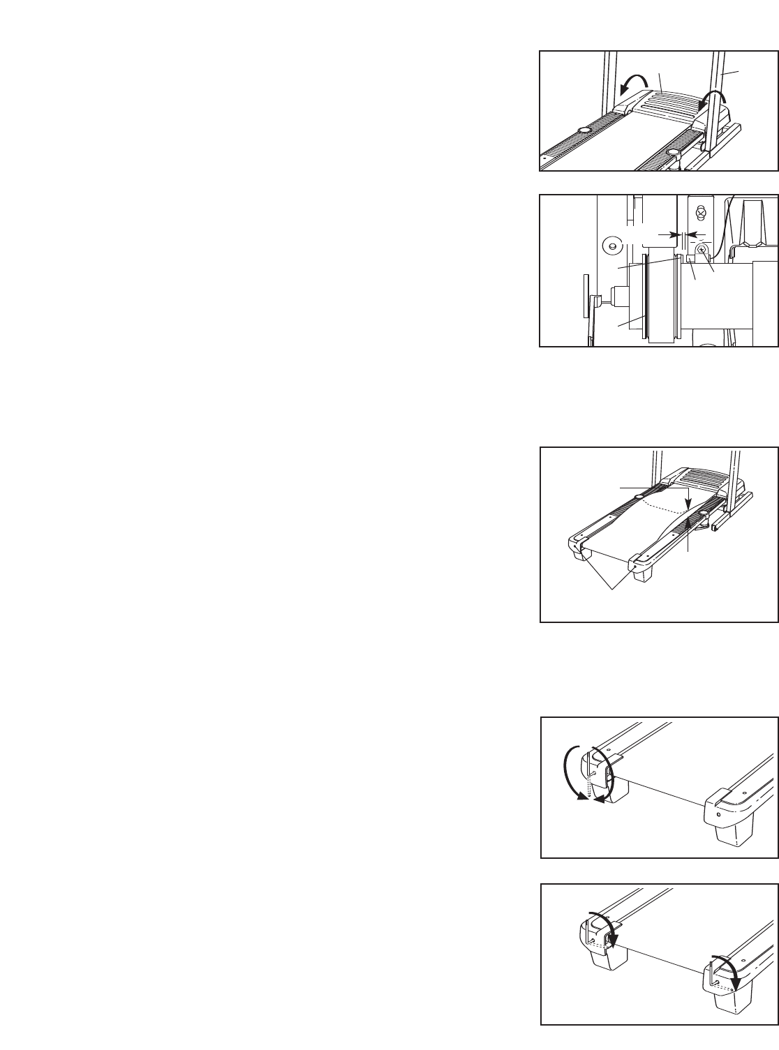
Note: The first time the treadmill is used, observe
the alignment of the walking belt, and center the
walking belt if necessary (see page 23).
Change the incline of the treadmill as desired.
To change the incline of
the treadmill, press the
Incline increase and de-
crease buttons. Each
time you press a button,
the incline will change by
0.5%. Note: After you press the buttons, it may
take a moment for the treadmill to reach the se-
lected incline setting.
Follow your progress with the display.
When the
manual mode
is selected,
the display
will show a
track that
represents
400 meters (1/4 mile). As you walk or run, the indi-
cators around the track will appear in succession
until the entire track appears. The track will then
disappear and the indicators will again begin to ap-
pear in succession.
5
4
3
2
1
Track
On
Position
Track
14
The left side of the dis-
play will show the
elapsed time, the dis-
tance that you have
walked or run, and the
incline level of the tread-
mill. Note: When a program is selected (except for
heart rate program 2), the display will show the
time remaining in the program instead of the
elapsed time.
The right side of the
display will show the
approximate number of
calories you have
burned, the speed of
the walking belt, and
your pace (in minutes per kilometer). The right side
of the display will also show your heart rate when
you use the handgrip pulse sensor or the optional
chest pulse sensor.
Note: The console can display speed and dis-
tance in either kilometers or miles. To find which
unit of measurement is selected, or to change the
unit of measurement, see THE INFORMATION
MODE on page 23. Note: For simplicity, all in-
structions in this section refer to kilometers.
To reset the display, press the Stop button, re-
move the key, and then reinsert the key.
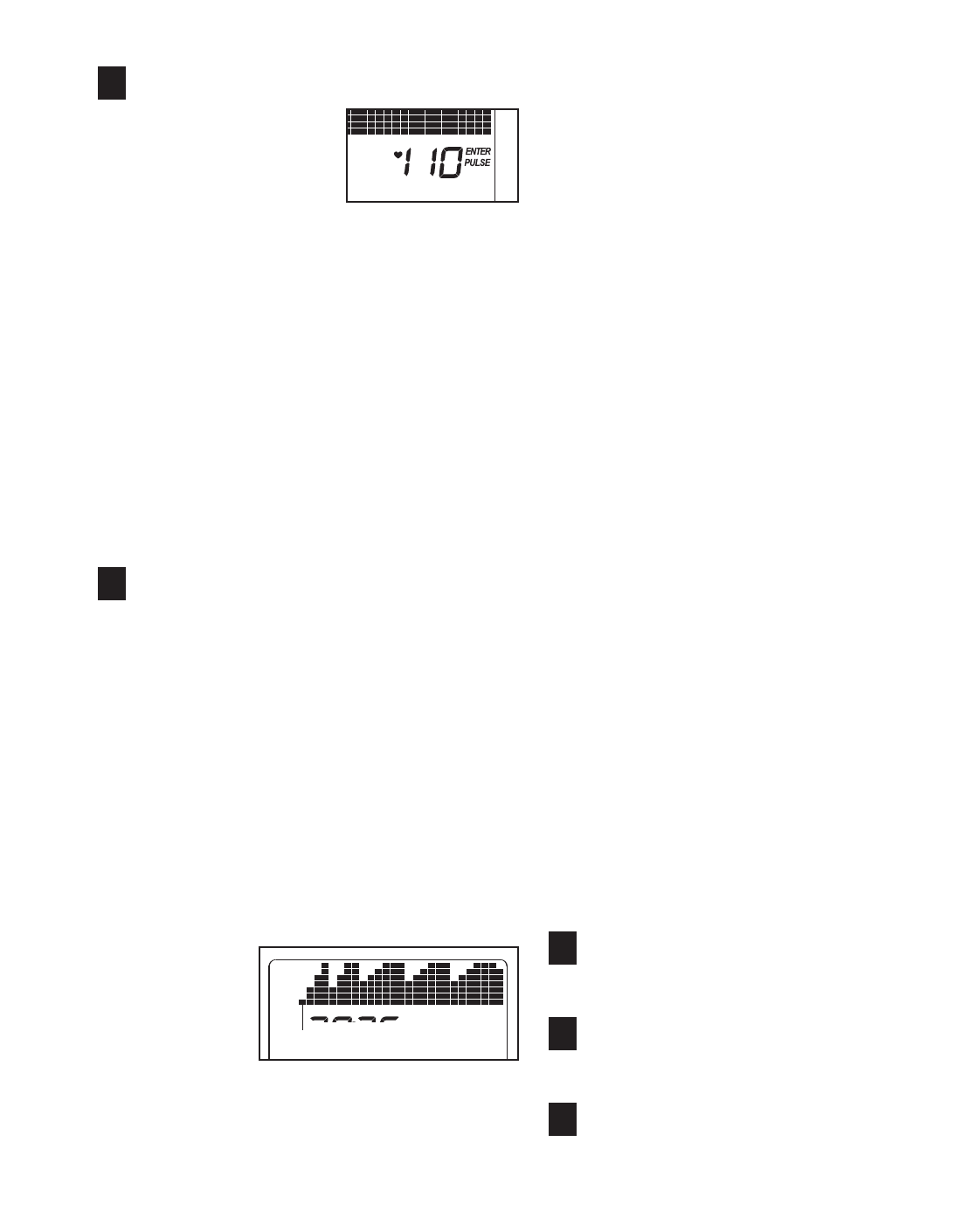
Measure your heart rate if desired.
Note: If you
use the
handgrip
pulse sensor
and the op-
tional chest
pulse sensor
at the same
time, the
console will not display your heart rate accurately.
Before using the handgrip pulse sensor, remove
the sheets of clear plastic from the metal contacts.
In addition, make sure that your hands are clean.
To measure your heart rate, stand on the foot
rails and hold the metal contacts on the
handrail—avoid moving your hands.When your
pulse is detected, the heart symbol in the right side
ofthe display will begin to flash each time your
heart beats, one or two dashes will appear, and
then your heart rate will be shown. For the most
accurate heart rate reading, continue to hold
the contacts for about 15 seconds.
Turn on the fan if desired.
To turn on the fan, press the Fan button. To turn
on the fan at high speed, press the button a sec-
ond time. To turn off the fan, press the button a
third time. Note: If the fan is left on when the walk-
ing belt is stopped, the fan will automatically turn
off after a few minutes.
When you are finished exercising, remove the
key.
Step onto the foot rails, press the Stop button, and
adjust the incline of the treadmill to the lowest
setting. The incline must be at the lowest setting
when you fold the treadmill to the storage posi-
tion you will damage the treadmill. Next, remove
the key from the console and put it in a secure
place. Note: If the display remains lit after the
key is removed, the console is in the “demo”
mode. See page 23 and turn off the demo mode.
When you are finished using the treadmill,
switch the on/off switch to the “off” position
and unplug the power cord.
8
7
6
Contacts
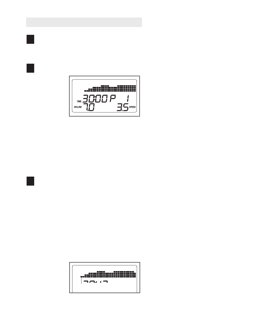
HOW TO USE A TRAINER PROGRAM
Insert the key into the console.
See HOW TO TURN ON THE POWER on page
13.
Select a trainer program.
To select
one of the
trainer pro-
grams,
press the
Trainer
Programs
button re-
peatedly
until one of the program indicators (“P1” through
“P10”) appears in the display. When a trainer pro-
gram is selected, the program time will appear in
the display, the maximum incline setting of the
program and the maximum speed setting of the
program will flash in the display for a few seconds,
and a profile of the speed settings of the program
will scroll across the display.
Press the Start button or the Speed increase
button to start the program.
Amoment after you press the button, the treadmill
will automatically adjust to the first speed and in-
cline settings of the program. Hold the handrails
and begin walking.
Each program is divided into 30, 50, or 60 one-
minute segments. One speed setting and one in-
cline setting are programmed for each segment.
Note: The same speed setting and/or incline setting
may be programmed for two or more consecutive
segments.
The speed
setting for
the first seg-
ment will be
shown in
the flashing
Current
Segment column of the display. (The incline set-
tings are not shown in the upper part of the dis-
play.) The speed settings for the next several seg-
ments will be shown in the columns to the right.
When only three seconds remain in the first seg-
ment of the program, both the Current Segment
column and the column to the right will flash and a
series of tones will sound. If the speed and/or in-
cline of the treadmill is about to change, the speed
setting and/or the incline setting will flash in the
display to alert you.
When the first segment is completed,
all speed
settings will move one column to the left
.The
speed setting for the second segment will then be
shown in the flashing Current Segment column
and the treadmill will automatically adjust to the
speed and incline settings for the second seg-
ment. Note: If all of the indicators in the Current
Segment column are lit,
the speed settings may
move downward
so that only the highest indicators
appear in the display.
The program will continue in this way until the
speed setting for the last segment is shown in the
Current Segment column and the last segment
ends. The walking belt will then slow to a stop.
If the speed or incline setting for the current seg-
ment is too high or too low, you can manually
override the setting by pressing the Speed or
Incline buttons. Every few times a Speed button is
pressed, an additional indicator will appear or dis-
appear in the Current Segment column; if any of
the columns to the right of the Current Segment
column have the same number of lit indicators as
the Current Segment column, an additional indica-
tor may appear or disappear in those columns as
well. Important: When the current segment
ends, the treadmill will automatically adjust to
the speed and incline settings for the next seg-
ment.
To stop the program at any time, press the Stop
button. The time will begin to flash in the display.
To restart the program, press the Start button or
the Speed increase button. The walking belt will
begin to move at 2 km/h. When the next segment
of the program begins, the treadmill will automati-
cally adjust to the speed and incline settings for the
next segment.
3
2
1
Current Segment
15
Follow your progress with the display.
See step 5 on page 13.
Measure your heart rate if desired.
See step 6 on page 14.
Turn on the fan if desired.
See step 7 on page 14.
When you are finished exercising, remove the
key from the console.
See step 8 on page 14.
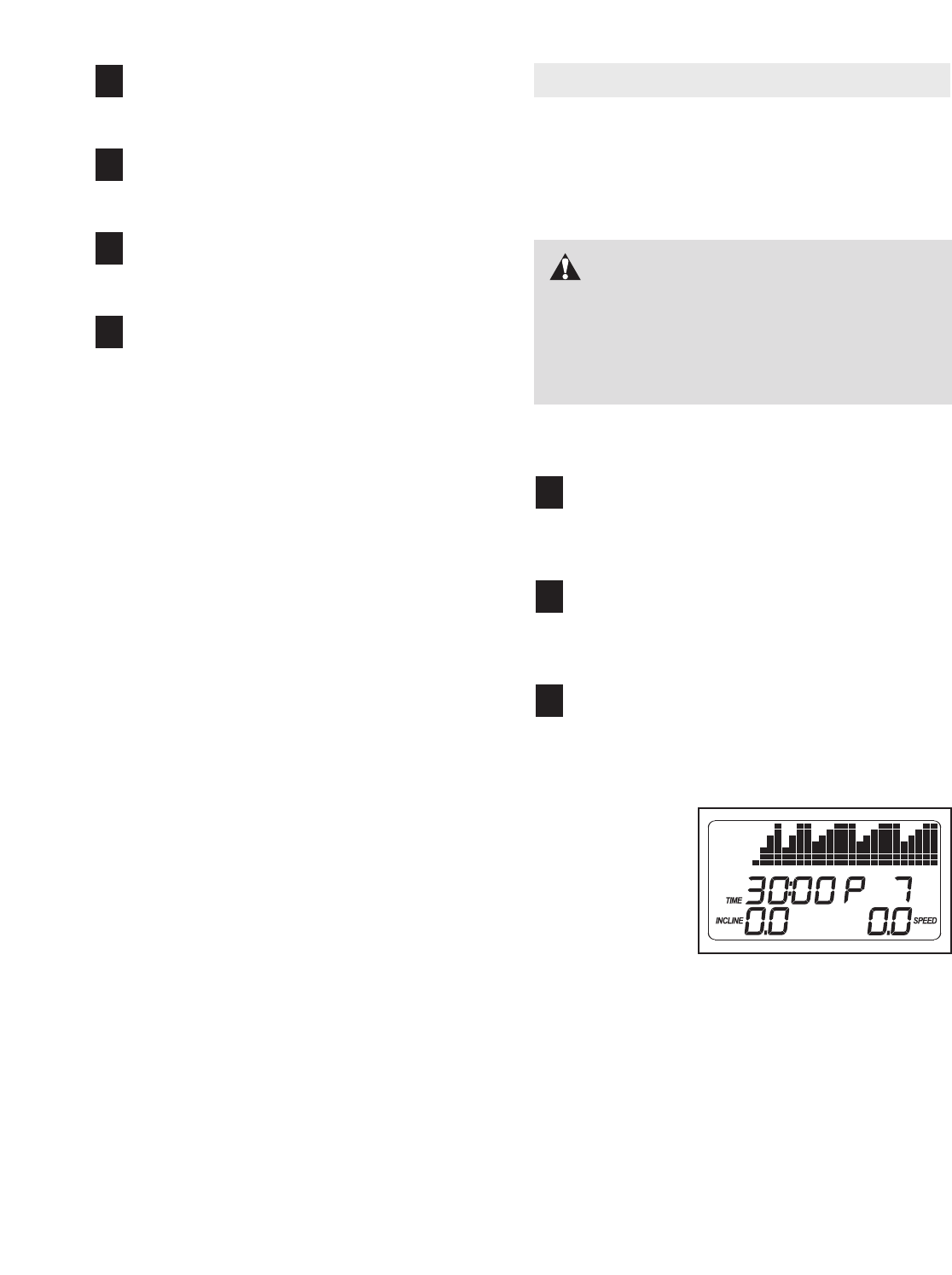
HOW TO USE A HEART RATE PROGRAM
Heart rate program 1 will automatically adjust the speed
and incline of the treadmill to keep your heart rate within
a preset range during your workout. Heart rate program
2 will keep your heart rate near a target heart rate setting
that you select.
Follow the steps below to use a heart rate program.
Put on the optional chest pulse sensor.
See the instructions included with the chest pulse
sensor.
Insert the key into the console.
See HOW TO TURN ON THE POWER on page
13.
Select a heart rate program.
To select a heart rate program, press the Heart
Rate Programs button repeatedly until “P1” or
“P2” appears in the display.
If heart rate
program 1
is selected,
aprofile of
the target
heart rate
settings of
the program
will scroll
across the display.
If heart rate program 2 is selected, agraphic
representing your heartbeat will appear in the dis-
play.
3
2
1
7
6
5
4
CAUTION: If you have heart prob-
lems, or if you are over 60 years of age and
have been inactive, do not use the heart rate
programs. If you are taking medication regu-
larly, consult your physician to find whether the
medication will affect your exercise heart rate.
16
Enter a target heart rate setting.
If heart rate program 1
is selected, the maxi-
mum target heart rate
setting of the program
will appear in the display.
Ifdesired, press the in-
crease and decrease buttons beside the Heart
Rate Programs button to change the maximum
target heart rate setting (see EXERCISE INTEN-
SITY on page 28). Note: If you change the maxi-
mum target heart rate setting, the intensity level of
the entire program will change.
If heart rate program 2 is selected, the target
heart rate setting for the program will be dis-
played. If desired, press the increase and de-
crease buttons beside the Heart Rate Programs
button to change the target heart rate setting (see
EXERCISE INTENSITY on page 28). Note: The
same target heart rate setting will be programmed
for the entire program.
Press the Start button or the Speed increase
button to start the program.
Amoment after you press the button, the treadmill
will automatically adjust to the first speed and in-
cline settings of the program. Hold the handrails
and begin walking.
Heart rate program 1 is divided into 30 one-minute
segments. One target heart rate setting is pro-
grammed for each segment. (Note: The same tar-
get heart rate setting may be programmed for two
or more consecutive segments.) Heart rate pro-
gram 2 is divided into 100 one-minute segments.
The same target heart rate setting is programmed
for all segments. Note: For a shorter workout, sim-
ply stop the program before it ends.
If heart rate
program 1 is
selected, the
target heart
rate setting
for the first
segment will
be shown in the flashing Current Segment column
of the display. The target heart rate settings for the
next several segments will be shown in the
columns to the right. When only three seconds re-
main in the first segment, both the Current
Segment column and the column to the right will
flash and a series of tones will sound. When the
first segment ends,
all target heart rate settings
will move one column to the left.
The target heart
rate setting for the second segment will then be
shown in the flashing Current Segment column.
During both heart rate programs, the console will
regularly compare your heart rate to the current
target heart rate setting. If your heart rate is too
far below or above the target heart rate setting,
the speed of the walking belt will automatically in-
crease or decrease to bring your heart rate closer
to the target heart rate setting. If the speed of the
walking belt reaches 12 km/h and your heart rate
is still too far below the target heart rate setting,
the incline of the treadmill will also increase.
If the speed or incline setting is too high or too low
at any time during the program, you can adjust the
setting with the Speed or Incline buttons. However,
each time the console compares your heart rate to
the target heart rate setting, the speed and/or in-
cline of the treadmill may automatically change to
bring your heart rate closer to the target heart rate
setting.
If your pulse is not detected during the program,
the letters “PLS” will flash in the display and the
speed and/or incline of the treadmill may automat-
ically decrease.
To stop the program at any time, press the Stop
button. The time will begin to flash in the display.
To restart the program, press the Start button or
the Speed increase button. The walking belt will
begin to move at 2 km/h. When the console com-
pares your heart rate to the target heart rate set-
ting, the speed and/or incline of the treadmill may
automatically change to bring your heart rate
closer to the target heart rate setting.
Follow your progress with the display.
See step 5 on page 13.
Turn on the fan if desired.
See step 7 on page 14.
When you are finished exercising, remove the
key from the console.
See step 8 on page 14.
8
7
6
5
4
Current Segment
17
HOW TO CONNECT THE TREADMILL TO USE
IFIT.COM PROGRAMS
To use iFIT.com MP3 or CD programs,you must
connect the treadmill to your MP3 player, CD player,
portable stereo, home stereo, or computer. See pages
18 and 19 for connecting instructions. To use iFIT.com
programs directly from our Web site,you must con-
nect the treadmill to your computer. See page 19 for
connecting instructions. To use iFIT.com video pro-
grams,you must connect the treadmill to your VCR.
See page 20 for connecting instructions.
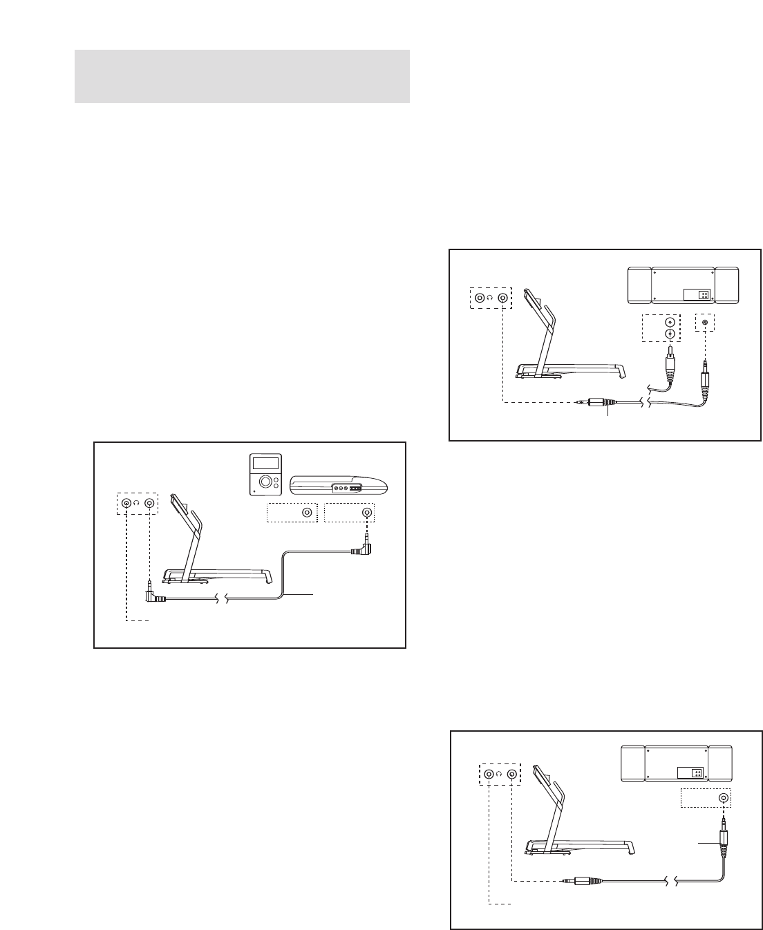
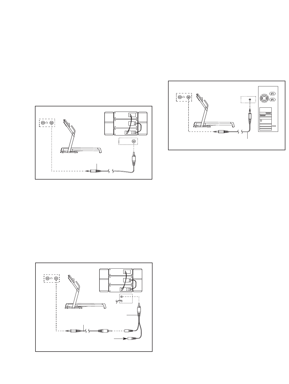
HOW TO CONNECT YOUR MP3 PLAYER OR CD
PLAYER
A. Plug one end of the included 3.5 mm to 3.5 mm
stereo audio cable into the input jack on the con-
sole. Plug the other end of the cable into a jack on
your MP3 player or CD player. Plug your head-
phones into the headphone jack on the console.
HOW TO CONNECT YOUR PORTABLE STEREO
Note: If your stereo has an RCA-type AUDIO OUT
jack, see instruction A below. If your stereo has a
3.5 mm LINE OUT jack, see instruction B. If your
stereo has only a PHONES jack, see instruction C.
A. Plug one end of a long 3.5 mm to RCA stereo audio
cable (available at electronics stores) into the input
jack on the console. Plug the other end of the cable
into the AUDIO OUT jack on your stereo.
B. See the drawing above. Plug one end of a long 3.5
mm to 3.5 mm stereo audio cable (available at elec-
tronics stores) into the input jack on the console.
Plug the other end of the cable into the LINE OUT
jack on your stereo. Note: While the cable is
plugged into the LINE OUT jack, do not plug your
headphones into the headphone jack on the con-
sole.
C. Plug one end of a long 3.5 mm to 3.5 mm stereo
audio cable (available at electronics stores) into the
input jack on the console. Plug the other end of the
cable into the PHONES jack on your stereo. Plug
your headphones into the headphone jack on the
console.
LINE OUT
PHONES LINE OUT
PHONES
Audio
Cable
Headphones
A
A
C
PHONES
AUDIO OUT
RIGHT
LEFT
LINE OUT
Audio Cable
A/B
A
C
PHONES
AUDIO OUT
RIGHT
LEFT
LINE OUT
Audio
Cable
C
Headphones
18
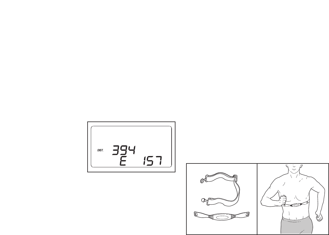
HOW TO CONNECT YOUR HOME STEREO
Note: If your stereo has an unused LINE OUT jack,
see instruction A below. If the LINE OUT jack is
being used, see instruction B.
A. Plug one end of a long 3.5 mm to RCA stereo audio
cable (available at electronics stores) into the input
jack on the console. Plug the other end of the cable
into the LINE OUT jack on your stereo. Note: While
the cable is plugged into the LINE OUT jack, do not
plug your headphones into the headphone jack on
the console.
B. Plug one end of a long 3.5 mm to RCA stereo audio
cable (available at electronics stores) into the input
jack on the console. Plug the other end of the cable
into an RCA Y-adapter (available at electronics
stores). Next, remove the wire that is currently
plugged into the LINE OUT jack on your stereo and
plug the wire into the unused side of the Y-adapter.
Plug the Y-adapter into the LINE OUT jack on your
stereo. Note: While the Y-adapter is plugged into the
LINE OUT jack, do not plug your headphones into
the headphone jack on the console.
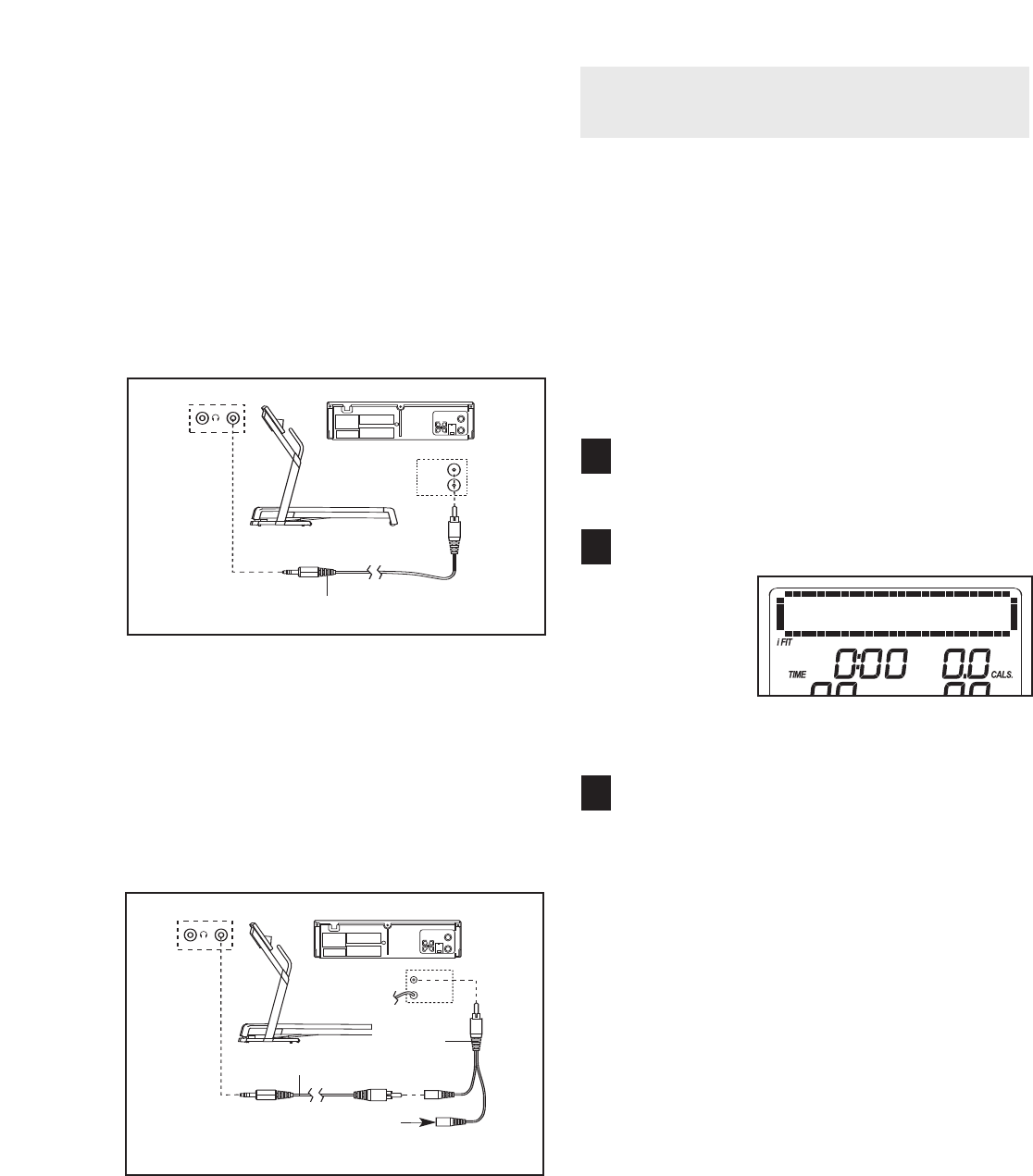
HOW TO CONNECT YOUR COMPUTER
A. Plug one end of a long 3.5 mm to 3.5 mm stereo
audio cable (available at electronics stores) into the
input jack on the console. Plug the other end of the
cable into the LINE OUT jack on your computer.
Note: While the cable is plugged into the LINE OUT
jack, do not plug your headphones into the head-
phone jack on the console.
B
A
CD
VCR
Amp
LINE OUT
LINE OUT
CD
VCR
Amp
LINE OUT
Audio Cable
A
B
A
CD
VCR
Amp
LINE OUT
LINE OUT
CD
VCR
Amp
LINE OUT
Audio
Cable
RCA
Y-adapter
Wire removed from
LINE OUT jack
B
A
LINE OUT
Audio Cable
A
19
HOW TO CONNECT YOUR VCR
Note: If your VCR has an unused AUDIO OUT jack,
see instruction A below. If the AUDIO OUT jack is
being used, see instruction B. If you have a TV
with a built-in VCR, see instruction B. If your VCR
is connected to your home stereo, see HOW TO
CONNECT YOUR HOME STEREO on page 19.
A. Plug one end of a long 3.5 mm to RCA stereo audio
cable (available at electronics stores) into the input
jack on the console. Plug the other end of the cable
into the AUDIO OUT jack on your VCR.
B. Plug one end of a long 3.5 mm to RCA stereo audio
cable (available at electronics stores) into the input
jack on the console. Plug the other end of the cable
into an RCA Y-adapter (available at electronics
stores). Next, remove the wire that is currently
plugged into the AUDIO OUT jack on your VCR and
plug the wire into the unused side of the Y-adapter.
Plug the Y-adapter into the AUDIO OUT jack on
your VCR.
HOW TO USE AN IFIT.COM MP3, CD, OR VIDEO
PROGRAM
To use an iFIT.com MP3, CD, or video program, you
must connect the treadmill to your MP3 player, CD
player, or VCR. See HOW TO CONNECT THE
TREADMILL TO USE IFIT.COM PROGRAMS on
pages 18 to 20. To download iFIT.com MP3 pro-
grams, go to www.iFIT.com. To purchase iFIT.com
CDs or videocassettes, call the telephone number
on the front cover of this manual.
Follow the steps below to use an iFIT.com MP3, CD,
or video program.
Insert the key into the console.
See HOW TO TURN ON THE POWER on page 13.
Select the iFIT.com mode.
To select the
iFIT.com
mode, press
the iFIT but-
ton. The let-
ters “iFIT”
will appear
in the display.
Press the Play button on your MP3 player, CD
player, or VCR.
Note: If you are using an iFIT.com CD, insert the
CD into your CD player; if you are using an
iFIT.com videocassette, insert the videocassette
into your VCR.
Amoment after the Play button is pressed, your
personal trainer will begin guiding you through
your workout. Simply follow your personal trainer’s
instructions. Note: If the time is flashing in the dis-
play, press the Start button or the Speed increase
button on the console. The treadmill will not re-
spond to an MP3, CD, or video program while the
time is flashing in the display.
During the program, an electronic “chirping” sound
will alert you when the speed and/or incline of the
treadmill is about to change. CAUTION: Always
listen for the “chirp” and be prepared for speed
and/or incline changes. In some instances, the
speed and/or incline may change before your
personal trainer describes the change.
3
2
1
B
VIDEO AUDIO
ANT. IN
RF OUT
IN
OUT
CH
34
A
AUDIO OUT
RIGHT
LEFT
VIDEO AUDIO
ANT. IN
RF OUT
IN
OUT
CH
34
Audio Cable
A
B
VIDEO AUDIO
ANT. IN
RF OUT
IN
OUT
CH
34
A
AUDIO OUT
RIGHT
LEFT
VIDEO AUDIO
ANT. IN
RF OUT
IN
OUT
CH
34
B
Wire removed from
AUDIO OUT jack
RCA
Y-adapter
Audio Cable
20

If the speed or incline settings are too high or too
low, you can manually override the settings at any
time by pressing the Speed or Incline buttons on
the console. However, when the next “chirp” is
heard, the speed and/or incline will change to
the next settings of the program.
To stop the walking belt at any time, press the
Stop button on the console. The time will begin to
flash in the display. To restart the program, press
the Start button or the Speed increase button.
After a moment, the walking belt will begin to
move at 2 km/h. When the next “chirp” is
heard, the speed and/or incline will change to
the next settings of the program.
When the program is completed, the walking belt
will stop. Note: To use another MP3, CD, or video
program, press the Stop button or remove the key
and go to step 1 on page 20.
Note: If the speed and/or incline of the treadmill
does not change when a “chirp” is heard:
•Make sure that the letters “iFIT” appear in the
display and that the time is not flashing in the
display. If the time is flashing, press the Start
button or the Speed increase button on the
console.
•Adjust the volume of your MP3 player, CD
player, or VCR. If the volume is too high or too
low, the console may not detect the program
signals.
•Make sure that the audio cable is properly
connected.
•If you are using a portable CD player and the
CD skips, set the CD player on the floor or an-
other flat surface instead of on the console.
Follow your progress with the display.
See step 5 on page 13.
Measure your heart rate if desired.
See step 6 on page 14.
Turn on the fan if desired.
See step 7 on page 14.
When you are finished exercising, remove the
key from the console.
See step 7 on page 17.
CAUTION: Always remove iFIT.com CDs and
videocassettes from your CD player and VCR
and disconnect your MP3 player when you are
not using them.
7
6
5
4
21

HOW TO USE AN IFIT.COM PROGRAM
DIRECTLY FROM OUR WEB SITE
Our Web site at www.iFIT.com allows you to access
programs directly from the internet. Additional options
are soon to be available. See www.iFIT.com for details.
To use programs from our Web site, you must connect
the treadmill to your home computer. See HOW TO
CONNECT YOUR COMPUTER on page 19. In
addition, you must have an internet connection and
an internet service provider. A list of specific system re-
quirements is found on our Web site.
Follow the steps below to use a program from our
Web site.
Insert the key into the console.
See HOW TO TURN ON THE POWER on page 13.
Select the iFIT.com mode.
See step 2 on page 20.
Go to your computer and start an internet
connection.
Start your web browser, if necessary, and go to
our Web site at www.iFIT.com.
Follow the desired links on our Web site to se-
lect a program.
Read and follow the on-line instructions for using a
program.
Follow the on-line instructions to start the
program.
When you start the program, an on-screen count-
down will begin.
Return to the treadmill and stand on the foot
rails. Find the clip attached to the key and slide
the clip onto the waistband of your clothes.
When the on-screen countdown ends, the program
will begin and the walking belt will begin to move.
Hold the handrails, step onto the walking belt, and
begin walking. During the program, an electronic
“chirping” sound will alert you when the speed
and/or incline of the treadmill is about to change.
CAUTION: Always listen for the “chirp” and be
prepared for speed and/or incline changes.
If the speed or incline settings are too high or too
low, you can manually override the settings at any
time by pressing the Speed or Incline buttons on
the console. However, when the next “chirp” is
heard, the speed and/or incline will change to
the next settings of the program.
To stop the walking belt at any time, press the
Stop button on the console. The time will begin to
flash in the display. To restart the program, press
the Start button or the Speed increase button.
After a moment, the walking belt will begin to
move at 2 km/h. When the next “chirp” is heard,
the speed and incline will change to the next
settings of the program.
When the program is completed, the walking belt
will stop.Note: To use another program, press the
Stop button and go to step 5.
Note: If the speed and/or incline of the treadmill
does not change when a “chirp” is heard, make
sure that the letters “iFIT” appear in the display
and that the time is not flashing in the display.
In addition, make sure that the audio cable is
properly connected.
Follow your progress with the display.
See step 5 on page 13.
When you are finished exercising, remove the
key from the console.
See step 7 on page 14.
9
8
7
6
5
4
3
2
1
22
23
THE INFORMATION MODE
The console features an information mode that keeps
track of treadmill usage information. The information
mode also allows you to select kilometers or miles as
the unit of measurement and to turn on and turn off the
demo mode.
To select the information mode, hold down the Stop
button, insert the key into the console, and then release
the Stop button. When the information mode is se-
lected, the following information will appear in the dis-
play:
The center of the
display will show
the total number
of kilometers or
miles that the
walking belt has
moved. The
lower part of the
display will show
the total number of hours that the treadmill has been
operated. In addition, an “M” for metric kilometers or an
“E” for English miles will appear in the lower part of the
display. To change the unit of measurement, press the
Speed increase button.
IMPORTANT: If a “d” appears in the display, the con-
sole is in the “demo” mode. This mode is intended to be
used only when a treadmill is displayed in a store.
When the console is in the demo mode, the power cord
can be plugged in, the key can be removed from the
console, and the indicators in the display will automati-
cally appear in a preset sequence; the buttons on the
console will not operate. If a “d” appears when the in-
formation mode is selected, press the Speed de-
crease button so “d” disappears.
To exit the information mode, remove the key from the
console.
THE OPTIONAL CHEST PULSE SENSOR
An optional chest pulse sensor adds even more fea-
tures to the console. The chest pulse sensor offers
hands-free operation, and enables you to use the con-
sole’s two heart rate programs. To purchase the op-
tional chest pulse sensor, call the telephone num-
ber on the front cover of this manual.
24
HOW TO FOLD AND MOVE THE TREADMILL
HOW TO FOLD THE TREADMILL FOR STORAGE
Before folding the treadmill, adjust the incline to the
lowest position. If this is not done, the treadmill may be per-
manently damaged. Next, unplug the power cord. CAUTION:
You must be able to safely lift 20 kg (45 lbs.) to raise, lower,
or move the treadmill.
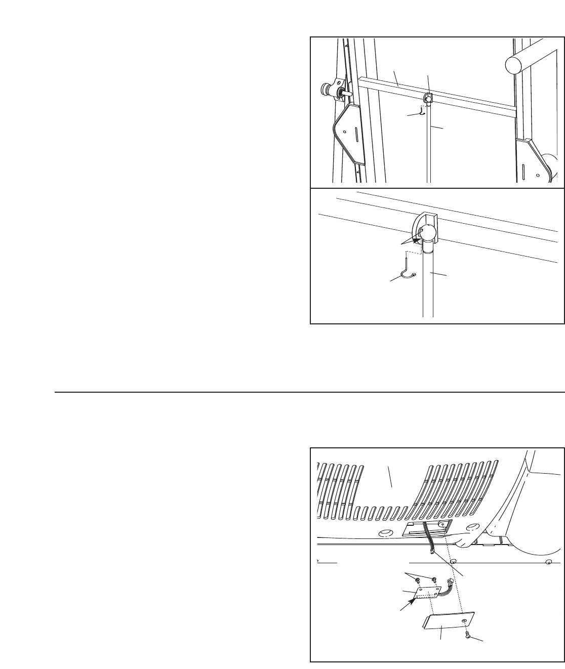
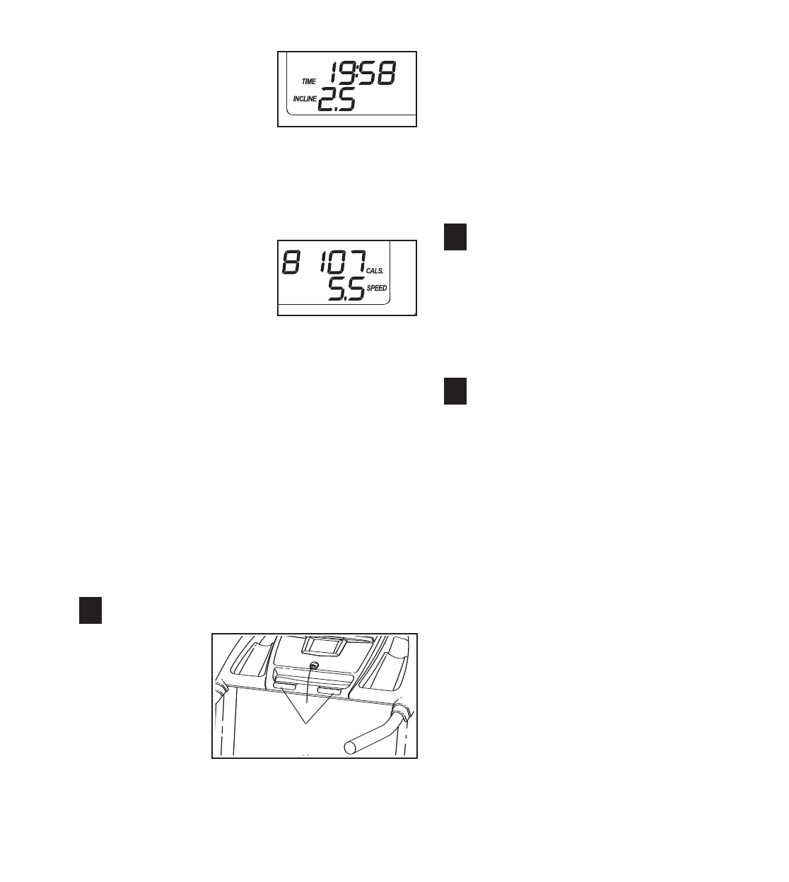
1. Hold the metal frame firmly in the location shown by the
arrow at the right. CAUTION: To decrease the possibility
of injury, do not lift the frame by the plastic foot rails.
Make sure you bend your legs and keep your back
straight. As you raise the frame, lift with your legs rather
than your back. Raise the frame about halfway to the vertical
position.
2. Move your right hand to the position shown and hold the
treadmill firmly. Using your left hand, pull the latch knob to
the left and hold it. Raise the frame until the latch catch is
aligned with the latch pin, and then slowly release the latch
knob. Make sure that the frame is held securely by the
latch pin, as shown.
To protect the floor or carpet from damage, place a mat
under the treadmill. Keep the treadmill out of direct sun-
light. Do not leave the treadmill in the storage position in
temperatures above 30° Celsius (85° Fahrenheit).
HOW TO MOVE THE TREADMILL
Before moving the treadmill, convert the treadmill to the storage
position as described above. Make sure that the frame is held
securely by the latch pin.
1. Hold one handrail with one hand, and place your other hand
on the deck. Place one foot against one of the wheels.
2. Tilt the treadmill back until it rolls freely on the wheels.
Carefully move the treadmill to the desired location. To re-
duce the risk of injury, use extreme caution while mov-
ing the treadmill. Do not move the treadmill over an un-
even surface.
3. Place one foot against one of the wheels, and carefully lower
the treadmill until it is resting in the storage position.
Handrails
Deck
Wheels
Engaged
Latch
Knob
Latch
Catch
Frame
25
HOW TO LOWER THE TREADMILL FOR USE
1. Hold the treadmill with your right hand as shown. Pull the
latch knob to the left and hold it. Pivot the frame down until it
is past the latch pin.
2. Hold the metal frame firmly with both hands,and lower it
to the floor. CAUTION: To decrease the possibility of in-
jury, do not lower the frame by gripping only the plastic
foot rails. Do not drop the frame to the floor. Make sure to
bend your legs and keep your back straight.
Frame
Latch
Knob
26
TROUBLESHOOTING
Most treadmill problems can be solved by following the steps below. Find the symptom that applies, and
follow the steps listed. If further assistance is needed, please see the front cover of this manual.
PROBLEM: The power does not turn on
SOLUTION: a. Make sure that the power cord is plugged into a properly earthed outlet (see page 11). If an exten-
sion cord is needed, use only a 3-conductor, 1 mm2(14-gauge) cord that is no longer than 1.5 m
(5 ft.). Important: The treadmill is not compatible with GFCI-equipped outlets.
b. After the power cord has been plugged in, make sure that the key is inserted into the console.
c. Check the circuit breaker located on the treadmill
near the power cord. If the switch protrudes as
shown, the circuit breaker has tripped. To reset the
circuit breaker, wait for five minutes and then press
the switch back in.
d. Check the on/off switch located on the treadmill
near the power cord. The switch must be in the
“on” position.
PROBLEM: The power turns off during use
SOLUTION: a. Check the circuit breaker located on the treadmill frame near the power cord (see the drawing
above). If the circuit breaker has tripped, wait for five minutes and then press the switch back in.
b. Make sure that the power cord is plugged in. If the power cord is plugged in, unplug it, wait for
five minutes, and then plug it back in.
c. Remove the key from the console. Reinsert the key into the console.
d. Make sure that the on/off switch is in the “on” position (see d. above).
e. If the treadmill still will not run, see the front cover of this manual.
PROBLEM: The displays of the console do not function properly
SOLUTION: a. Remove the key from the console and UNPLUG THE
POWER CORD. With the help of a second person,
carefully tip the Uprights (84) down as shown. Next, re-
move the three Screws (3) and the three 3/4” Screws
(83). Note: A phillips screwdriver with a shaft at least
5” long is required.
Tripped
c
Reset
On
Position
d
3
84
a3 83
With the help of a second person, carefully raise the
Uprights (84) to the position shown. Carefully pivot the
Hood (41) off.
Locate the Reed Switch (63) and the Magnet (46) on
the left side of the Pulley (47). Turn the Pulley until the
Magnet is aligned with the Reed Switch. Make sure
that the gap between the Magnet and the Reed
Switch is about 3 mm (1/8 in.). If necessary, loosen
the Screw (3), move the Reed Switch slightly, and
then retighten the Screw. Reattach the Hood, and run
the treadmill for a few minutes to check for a correct
speed reading.
PROBLEM: The walking belt slows when walked on
SOLUTION: a. If an extension cord is needed, use only a 3-conductor, 1mm2(14-gauge) cord that is no longer
than 1.5 m (5 ft.).
b. If the walking belt is overtightened, treadmill perfor-
mance may decrease and the walking belt may be-
come damaged. Remove the key and UNPLUG THE
POWER CORD.Using the hex key, turn both rear
roller bolts counterclockwise, 1/4 of a turn. When the
walking belt is properly tightened, you should be able
to lift each edge of the walking belt 5 to 7 cm (2 to 3
in.) off the walking platform. Be careful to keep the
walking belt centered. Then, plug in the power cord,
insert the key, and run the treadmill for a few minutes.
Repeat until the walking belt is properly tightened.
c. If the walking belt still slows when walked on, please see the front cover of this manual.
PROBLEM: The walking belt is off-center or slips when walked on
SOLUTION: a. If the walking belt is off-center, first remove the key
and UNPLUG THE POWER CORD.If the walking
belt has shifted to the left, use the hex key to turn
the left rear roller bolt clockwise 1/2 of a turn; if the
walking belt has shifted to the right, turn the left
bolt counterclockwise 1/2 of a turn. Be careful not to
overtighten the walking belt. Plug in the power cord,
insert the key, and run the treadmill for a few minutes.
Repeat until the walking belt is centered.
b. If the walking belt slips when walked on, first remove
the key and UNPLUG THE POWER CORD.Using
the hex key, turn both rear roller bolts clockwise, 1/4
of a turn. When the walking belt is correctly tightened,
you should be able to lift each edge of the walking
belt 5 to 7 cm (2 to 3 in.) off the walking platform. Be
careful to keep the walking belt centered. Then, plug
in the power cord, insert the key, and carefully walk
on the treadmill for a few minutes. Repeat until the
walking belt is properly tightened.
Rear Roller Bolts
5–7 cm
b
a
b
46 3
63
Top
View
47
41 84
3mm
27
28
CONDITIONING GUIDELINES
The following guidelines will help you to plan your ex-
ercise program. For more detailed exercise informa-
tion, obtain a reputable book or consult your physician.
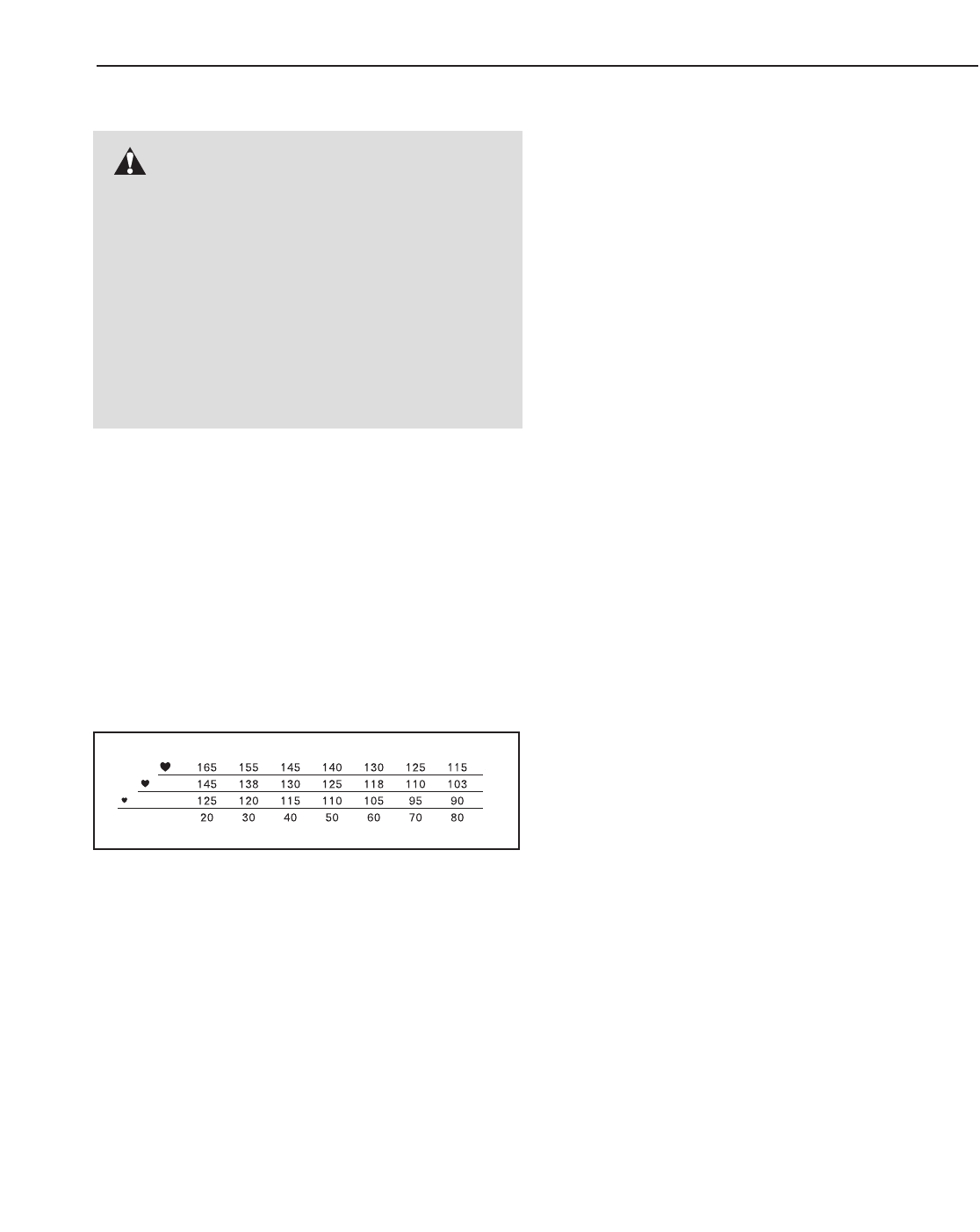
EXERCISE INTENSITY
Whether your goal is to burn fat or to strengthen your
cardiovascular system, the key to achieving the
desired results is to exercise with the proper intensity.
The proper intensity level can be found by using your
heart rate as a guide. The chart below shows recom-
mended heart rates for fat burning and aerobic exercise.
To find the proper heart rate for you, first find your age
near the bottom of the chart (ages are rounded off to
the nearest ten years). Next, find the three numbers
above your age. The three numbers define your “train-
ing zone.” The lower two numbers are recommended
heart rates for fat burning; the higher number is the
recommended heart rate for aerobic exercise.
Fat Burning
To burn fat effectively, you must exercise at a relatively
low intensity level for a sustained period of time.
During the first few minutes of exercise, your body
uses easily accessible
carbohydrate calories
for en-
ergy. Only after the first few minutes does your body
begin to use stored
fat calories
for energy. If your goal
is to burn fat, adjust the speed and incline of the tread-
mill until your heart rate is near the lowest number in
your training zone.
For maximum fat burning, adjust the speed and incline
of the treadmill until your heart rate is near the middle
number in your training zone.
Aerobic Exercise
If your goal is to strengthen your cardiovascular sys-
tem, your exercise must be “aerobic.” Aerobic exercise
is activity that requires large amounts of oxygen for
prolonged periods of time. This increases the demand
on the heart to pump blood to the muscles, and on the
lungs to oxygenate the blood. For aerobic exercise,
adjust the speed and incline of the treadmill until your
heart rate is near the highest number in your training
zone.
WORKOUT GUIDELINES
Each workout should include the following three parts:
AWarm-up—Start each workout with 5 to 10 minutes
of stretching and light exercise. A proper warm-up in-
creases your body temperature, heart rate and circula-
tion in preparation for exercise.
Training Zone Exercise—After warming up, increase
the intensity of your exercise until your pulse is in your
training zone for 20 to 60 minutes. (During the first few
weeks of your exercise program, do not keep your
pulse in your training zone for longer than 20 minutes.)
Breathe regularly and deeply as you exercise—never
hold your breath.
ACool-down—Finish each workout with 5 to 10 min-
utes of stretching to cool down. This will increase the
flexibility of your muscles and will help prevent post-
exercise problems.
EXERCISE FREQUENCY
To maintain or improve your condition, complete three
workouts each week, with at least one day of rest be-
tween workouts. After a few months, you may com-
plete up to five workouts each week if desired. The key
to success is to make exercise a regular and enjoyable
part of your everyday life.
WARNING: Before beginning this
or any exercise program, consult your physi-
cian. This is especially important for individu-
als over the age of 35 or individuals with pre-
existing health problems.
The pulse sensor is not a medical device.
Various factors, including your movement,
may affect the accuracy of heart rate readings.
The pulse sensor is intended only as an exer-
cise aid in determining heart rate trends in
general.
29
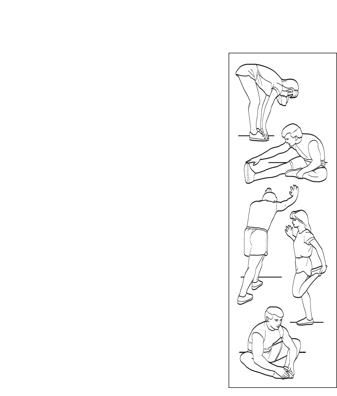
SUGGESTED STRETCHES
The correct form for several basic stretches is shown at the right. Move slowly as you stretch—never bounce.
1.Toe Touch Stretch
Stand with your knees bent slightly and slowly bend forward from
your hips. Allow your back and shoulders to relax as you reach
down toward your toes as far as possible. Hold for 15 counts, then
relax. Repeat 3 times. Stretches: Hamstrings, back of knees and
back.
2. Hamstring Stretch
Sit with one leg extended. Bring the sole of the opposite foot toward
you and rest it against the inner thigh of your extended leg. Reach
toward your toes as far as possible. Hold for 15 counts, then relax.
Repeat 3 times for each leg. Stretches: Hamstrings, lower back and
groin.
3. Calf/Achilles Stretch
With one leg in front of the other, reach forward and place your
hands against a wall. Keep your back leg straight and your back foot
flat on the floor. Bend your front leg, lean forward and move your
hips toward the wall. Hold for 15 counts, then relax. Repeat 3 times
for each leg. To cause further stretching of the achilles tendons,
bend your back leg as well. Stretches: Calves, achilles tendons and
ankles.
4. Quadriceps Stretch
With one hand against a wall for balance, reach back and grasp one
foot with your other hand. Bring your heel as close to your buttocks
as possible. Hold for 15 counts, then relax. Repeat 3 times for each
leg. Stretches: Quadriceps and hip muscles.
5. Inner Thigh Stretch
Sit with the soles of your feet together and your knees outward. Pull
your feet toward your groin area as far as possible. Hold for 15
counts, then relax. Repeat 3 times. Stretches: Quadriceps and hip
muscles.
1
2
3
4
5

30
PART LIST—Model No. PETL40906.1 R0408A
Key No. Qty. Description Key No. Qty. Description
1 2 Isolator Decal
2 8 3/4” Tek Screw
3 25 Screw
4 1 Catch
5 8 Foot Rail Screw
6 4 Front Isolator
7 4 Isolator Washer/Roller Washer
8 8 Star Washer
9 2 Platform Bolt, Back
10 2 Platform Bolt, Front
11 4 Belt Guide Screw
12 2 Belt Guide
13 2 Motor Isolator
14 1 Power Cord Adapter
15 2 Frame Pivot Bolt
16 1 Left Foot Rail
17 1 Right Foot Rail
18 9 U-nut
19 1 Static Decal
20 1 Handrail
21 1 Latch Pin Assembly
22 6 1” Tek Screw
23 1 Console Ground Wire
24 2 Motor Bolt
25 2 Shock Clip
26 1 Motor Belt
27 1 Drive Motor
28 2 Frame Washer
29 1 Outlet Assembly
30 1 Filter Wire
31 2 Lift Frame Bolt
32 6 Lock Nut
33 17 1/2” Screw
34 1Console
35 2 Fan Screw
36 1 Power Cord
37 1Console Fan
38 1 Controller
39 1 Electronics Bracket
40 3Roller Star Washer
41 1 Hood
42 1 Front Roller Bushing
43 1 Lift Frame
44 2Upright Endcap
45 1 Front Roller Bolt
46 1 Magnet
47 1Front Roller
48 1 Walking Belt
49 1 Walking Platform
50 1 Filter
51 1 Rear Roller
52 1 Left Rear Endcap
53 2 Rear Roller Bolt
54 1 Right Rear Endcap
55 1 Hex Key
56 1 Incline Stop Bracket
57 1 Ground Wire
58 1 Frame
59 1 Belly Pan
60 1 Reed Switch Bracket
61 1 Reed Switch Clip
62 1 Front Roller Nut
63 1 Reed Switch
64 8 Handrail Bolt/Extension Leg Bolt
65 2 Handrail Endcap
66 4 Star Washer
67 1 Transformer
68 2 Caution Decal
69 1 Warning Decal
70 2 Platform Nut
71 12 Cable Tie
72 1 Cotter Pin, Bottom
73 1 Latch Housing
74 3 Tie Clamp
75 1 Releasable Tie
76 1 Access Door
77 1 Upright Wire Harness
78 1 Console Wire Harness
79 1 Key/Clip
80 2 Front Wheel
81 2Wheel Bolt
82 6 Base Pad
83 11 3/4” Screw
84 1 Upright
85 1 Console Base
86 1 Cotter Pin, Top
87 2Hair Pin Cotter Pin
88 1 Incline Motor
89 2 Extension Leg
90 2 Rear Roller Bracket
91 2Isolator
92 1 Shock
93 2 Isolator Bracket Cover
94 2Isolator Bolt, Bottom

31
95 1 Idler Arm Pivot Bolt
96 1 Idler Arm Spacer
97 1 Idler Arm
98 1 Idler Arm Spring
99 1 Idler Arm Washer
100 1 Idler Arm Nut
101 1 Idler Arm Pulley
102 1 Pulley Bolt
# 1 6” Blue Wire, 2F
#1 4” Red Wire, M/F
# 1 User’s Manual
“#” indicates a non-illustrated part.
Specifications are subject to change without notice.
16
5
9
12
11
15
10 46
47
10
49
48
9
58
51
53
40
52
54
33
57
53
12
15
55
70
70
11
69
5
5
5
83
83
93
94
1
1
94
5
5
90
90
93
91
3
6
6
3
40
17
91
2
2
7
7
5
5
4
3
7
7
6
3
3
6
32
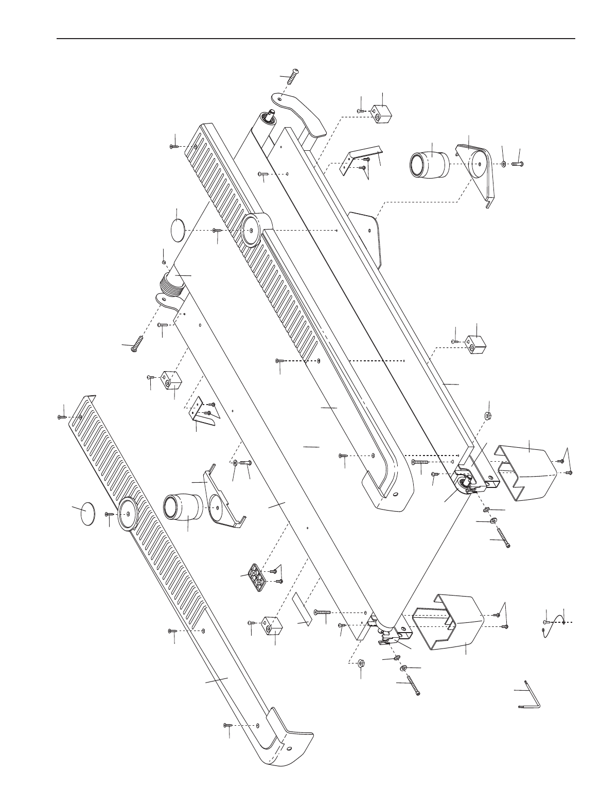
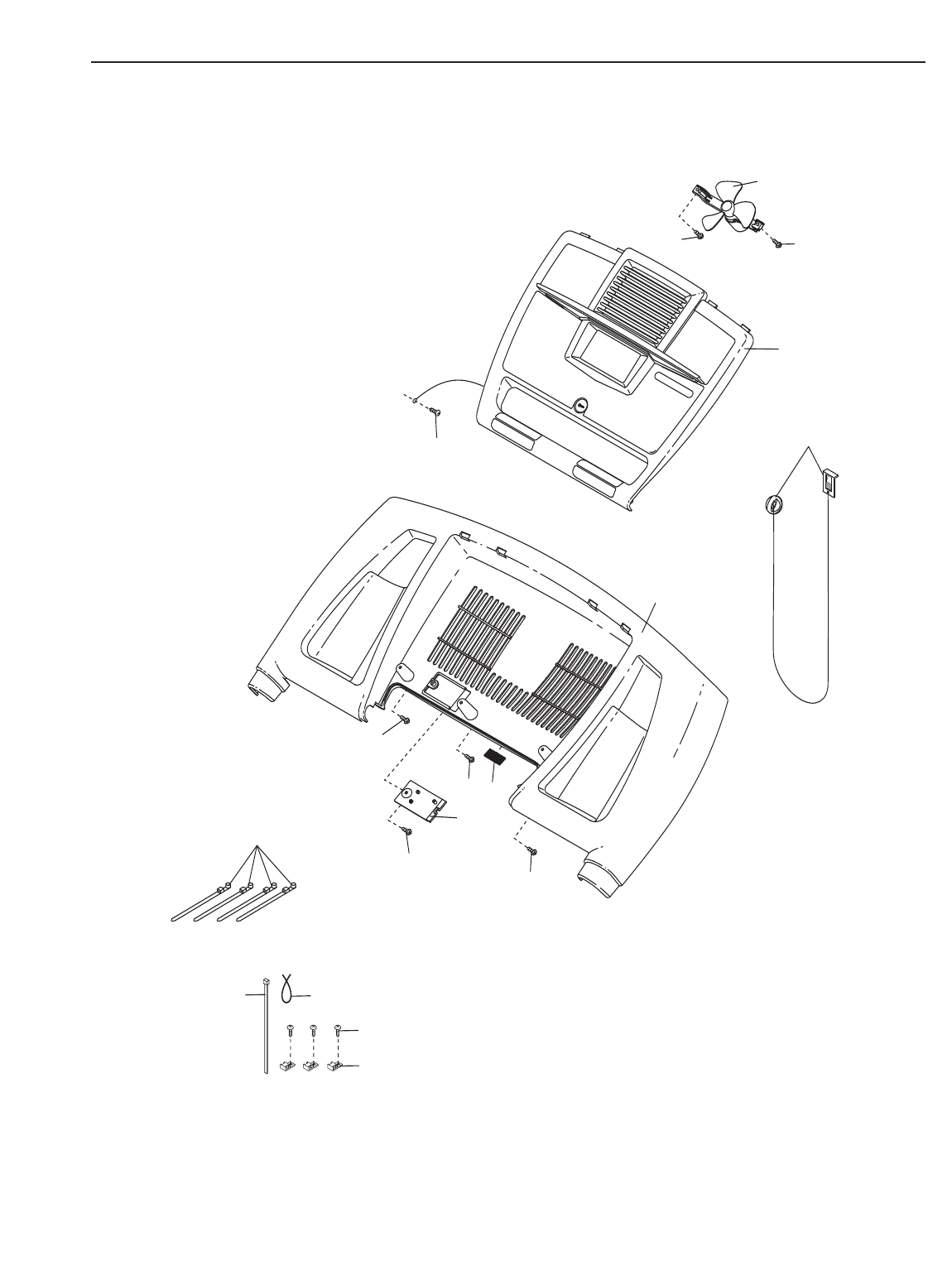
EXPLODED DRAWING—Model No. PETL40906.1 R0408A
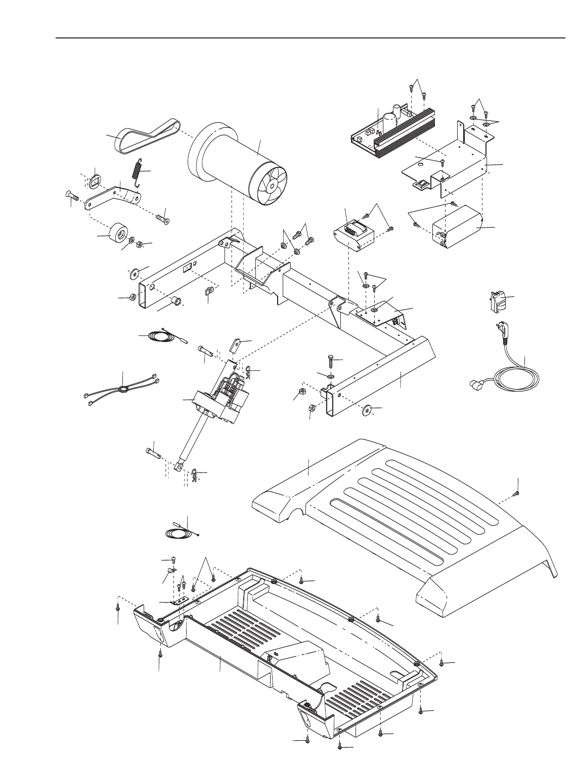
28
43
28
32
32
62
66
27
26
42
24
33
36
101
95
102
98
97
99
96
100
18
63
2
359
60
83
2
33
61
83
83
2
2
2
3
41
83
3
30
33
66
33
38
33
33
39
29
66
33
50
67
14
13
72
87
86
88
56
87
45
40
63
33
EXPLODED DRAWING—Model No. PETL40906.1 R0408A
3
73
18
77
8
64
20
8
18
65
65
3
3
3
3
8
64
8
3
3
3
3
3
84
82
22
82 22
68
68
8
31
32
3
44
3
44
31
32
21
92
25
33 77
81
32
80 82
22
89 82
22
82
22
64
81
32
80
82
22
89
8
64
18
18
34
EXPLODED DRAWING—Model No. PETL40906.1 R0408A
3
76
79
75
33
74
71
34
85
3
3
3
19
37
35
35
33
78
35
EXPLODED DRAWING—Model No. PETL40906.1 R0408A

Part No. 250199 R0408A Printed in China © 2008 ICON IP, Inc.
ORDERING REPLACEMENT PARTS
To order replacement parts, contact the ICON Health & Fitness, Ltd. office, or write:
ICON Health & Fitness, Ltd.
Customer Service Department
Unit 4, Revie Road Industrial Estate
Revie Road
Beeston
Leeds, LS118JG
UK
Tel:
Outside the UK: (44) 0113 387 7133
Fax: (44) 0113 387 7125
To help us assist you, please be prepared to give the following information:
• the MODEL NUMBER of the product (PETL40906.1)
• the NAME of the product (PROFORM 480 CX treadmill)
• the SERIAL NUMBER of the product (see the front cover of this manual)
• the KEY NUMBER and DESCRIPTION of the desired part(s) (see the PART LIST and the EXPLODED
DRAWING on pages 30-35 of this manual)
08457 089 009
