Proform Pfel799071 Perspective 1000 Elliptical Users Manual PFEL79907.1 262398
PFEL79907.1 to the manual 406b78bc-2cbf-4f35-98a6-31f55723cc71
2015-04-14
: Proform Proform-Pfel799071-Perspective-1000-Elliptical-Users-Manual-700121 proform-pfel799071-perspective-1000-elliptical-users-manual-700121 proform pdf
Open the PDF directly: View PDF ![]() .
.
Page Count: 32
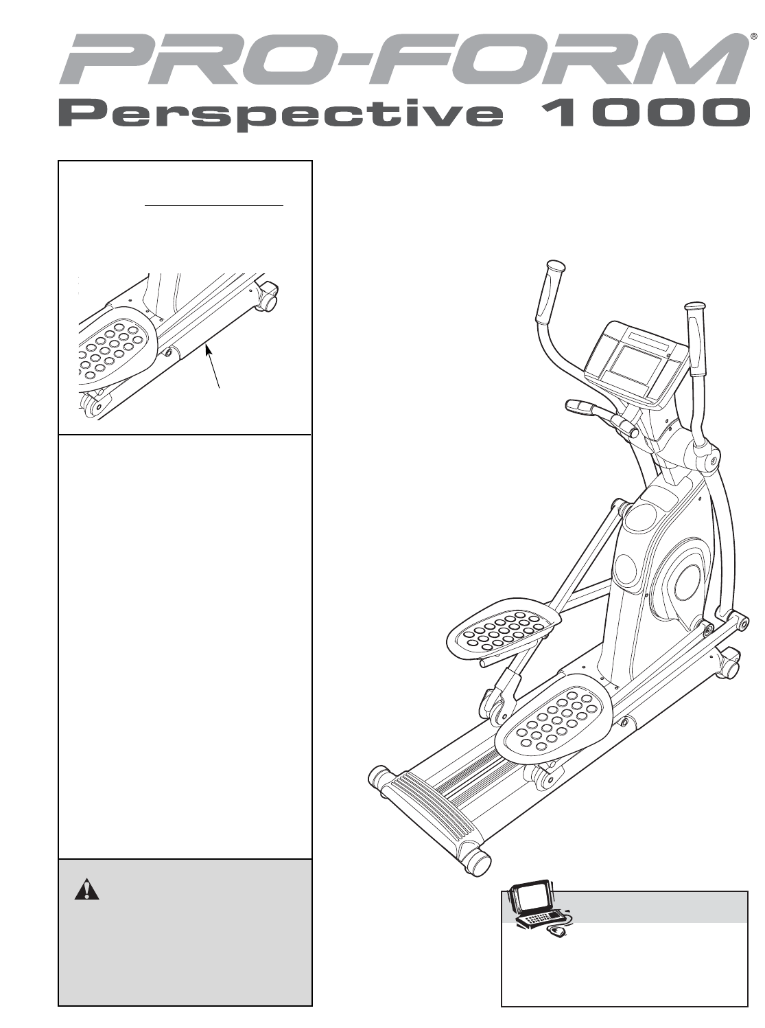
Model No. PFEL79907.1
Serial No.
Write the serial number in the space
above for reference.
USER’S MANUAL
Visit our website at
www.proform.com
new products, prizes,
fitness tips, and much more!
Serial Number Decal
(on underside of frame)
QUESTIONS?
As a manufacturer, we are commit-
ted to providing complete customer
satisfaction. If you have questions,
or if parts are damaged or missing,
PLEASE DO NOT CONTACT THE
STORE; please contact Customer
Care.
IMPORTANT: You must note the
product model number and serial
number (see the drawing above)
before contacting us:
CALL TOLL-FREE:
1-888-533-1333
Mon.–Fri. 6 a.m.–6 p.m. MST
Sat. 8 a.m.–4 p.m. MST
ON THE WEB:
www.proformservice.com
CAUTION
Read all precautions and instruc-
tions in this manual before using
this equipment. Keep this manual
for future reference.
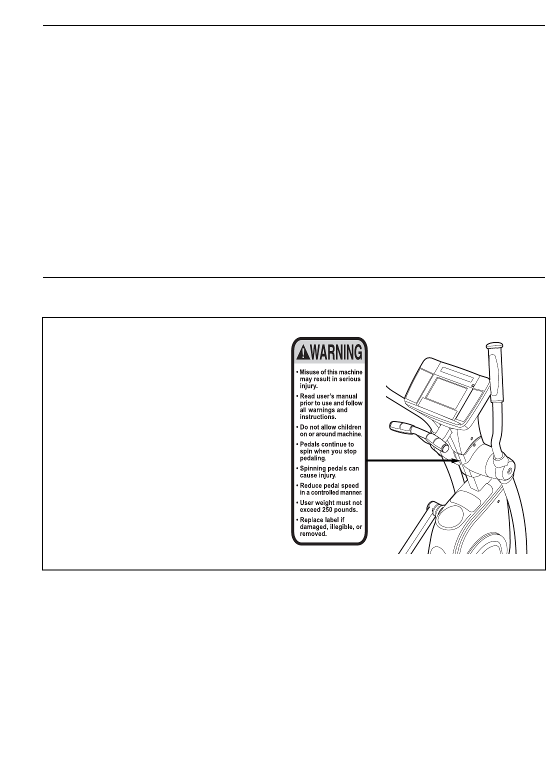
TABLE OF CONTENTS
WARNING DECAL PLACEMENT . . . . . . . . . . . . . . . . . . . . . . . . . . . . . . . . . . . . . . . . . . . . . . . . . . . . . . . . . . . . . .2
IMPORTANT PRECAUTIONS . . . . . . . . . . . . . . . . . . . . . . . . . . . . . . . . . . . . . . . . . . . . . . . . . . . . . . . . . . . . . . . .3
BEFORE YOU BEGIN . . . . . . . . . . . . . . . . . . . . . . . . . . . . . . . . . . . . . . . . . . . . . . . . . . . . . . . . . . . . . . . . . . . . . .4
ASSEMBLY . . . . . . . . . . . . . . . . . . . . . . . . . . . . . . . . . . . . . . . . . . . . . . . . . . . . . . . . . . . . . . . . . . . . . . . . . . . . . . .5
HOW TO USE THE ELLIPTICAL EXERCISER . . . . . . . . . . . . . . . . . . . . . . . . . . . . . . . . . . . . . . . . . . . . . . . . . .13
MAINTENANCE AND TROUBLESHOOTING . . . . . . . . . . . . . . . . . . . . . . . . . . . . . . . . . . . . . . . . . . . . . . . . . . .23
EXERCISE GUIDELINES . . . . . . . . . . . . . . . . . . . . . . . . . . . . . . . . . . . . . . . . . . . . . . . . . . . . . . . . . . . . . . . . . . .25
PART LIST . . . . . . . . . . . . . . . . . . . . . . . . . . . . . . . . . . . . . . . . . . . . . . . . . . . . . . . . . . . . . . . . . . . . . . . . . . . . . .28
EXPLODED DRAWING . . . . . . . . . . . . . . . . . . . . . . . . . . . . . . . . . . . . . . . . . . . . . . . . . . . . . . . . . . . . . . . . . . . .30
ORDERING REPLACEMENT PARTS . . . . . . . . . . . . . . . . . . . . . . . . . . . . . . . . . . . . . . . . . . . . . . . . . .Back Cover
LIMITED WARRANTY . . . . . . . . . . . . . . . . . . . . . . . . . . . . . . . . . . . . . . . . . . . . . . . . . . . . . . . . . . . . . .Back Cover
2
PROFORM is a registered trademark of ICON IP, Inc.
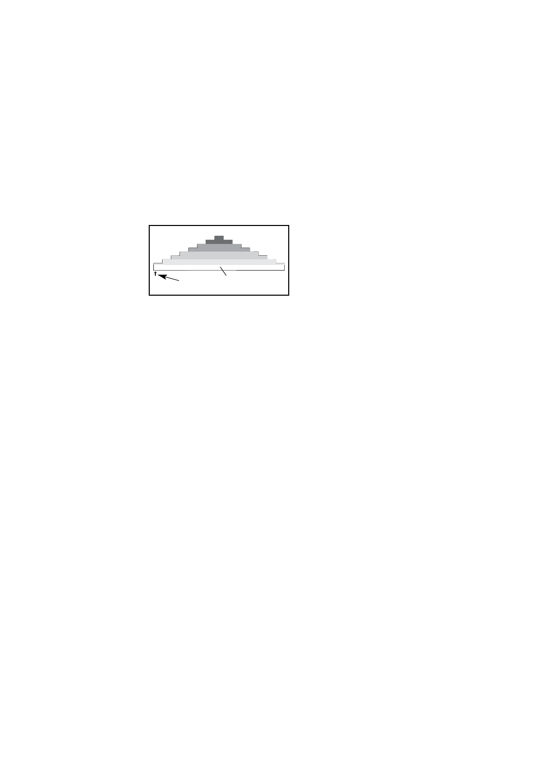
WARNING DECAL PLACEMENT
The warning decal shown at the right has
been applied in the location shown. If the
decal is missing or illegible, call the
telephone number on the front cover of
this manual and request a free replace-
ment decal. Apply the decal in the loca-
tion shown. Note: The decal may not be
shown at actual size.

3
1. Before beginning any exercise program,
consult your physician. This is especially
important for persons over the age of 35 or
persons with pre-existing health problems.
2. It is the responsibility of the owner to ensure
that all users of the elliptical exerciser are
adequately informed of all precautions.
3. Your elliptical exerciser is intended for home
use only. Do not use your elliptical exerciser
in a commercial, rental, or institutional set-
ting.
4. Keep your elliptical exerciser indoors, away
from moisture and dust. Place your elliptical
exerciser on a level surface, with a mat
beneath it to protect the floor or carpet.
Make sure that there is enough clearance
around your elliptical exerciser to mount,
dismount, and use it.
5. Inspect and properly tighten all parts regu-
larly. Replace any worn parts immediately.
6. Keep children under age 12 and pets away
from your elliptical exerciser at all times.
7. Your elliptical exerciser should not be used
by persons weighing more than 250 lbs.
(113 kg).
8. Wear appropriate exercise clothes when
exercising; do not wear loose clothes that
could become caught on your elliptical exer-
ciser. Always wear athletic shoes for foot
protection.
9. Hold the handgrip pulse sensor or the upper
body arms when mounting, dismounting, or
using your elliptical exerciser.
10. Keep your back straight while using your
elliptical exerciser; do not arch your back.
11. The pulse sensor is not a medical device.
Various factors, including the user’s move-
ment, may affect the accuracy of heart rate
readings. The pulse sensor is intended only
as an exercise aid in determining heart rate
trends in general.
12. When you stop exercising, allow the pedals
to slowly come to a stop.
13. If you feel pain or dizziness while exercising,
stop immediately and cool down.
14. Use your elliptical exerciser only as
described in this manual.
15. To reduce the risk of electric shock, do not
remove the cover or the back of the televi-
sion. There are no user serviceable parts
inside. Refer servicing to qualified service
personnel.
16. To protect the treadmill and TV during light-
ning storms, unplug the power cord from
the wall outlet and disconnect the cable sys-
tem. This will prevent damage due to light-
ning and power line surges.
17. Upon completion of any service or repairs
to the treadmill or the television, ask the
service technician to perform safety checks
to confirm that the unit is in proper operat-
ing condition.
Note to CATV system installer: This reminder is
provided to call the CATV system installer’s
attention to Article 820-40 of the NEC that pro-
vides guidelines for proper grounding and, in
particular, specifies that the cable ground shall
be connected to the grounding system of the
building, as close to the point of cable entry as
practical.
WARNING: To reduce the risk of serious injury, read all important precautions and
instructions in this manual and all warnings on your elliptical exerciser before using your elliptical
exerciser. ICON assumes no responsibility for personal injury or property damage sustained by or
through the use of this product.
IMPORTANT PRECAUTIONS
4
BEFORE YOU BEGIN
Thank you for selecting the revolutionary PROFORM®
PERSPECTIVE 1000 elliptical exerciser. The PER-
SPECTIVE 1000 elliptical exerciser provides a wide
array of features, including a personal television,
designed to make your workouts at home more effec-
tive and enjoyable.
For your benefit, read this manual carefully before
you use the elliptical exerciser. If you have ques-
tions after reading this manual, please see the front
cover of this manual. To help us assist you, note the
product model number and serial number before con-
tacting us. The model number and the location of th
serial number decal are shown on the front cover of
this manual for the location of the decal.
To avoid a registration fee for any service needed
under warranty, you must register the exerciser at
www.proformservice.com/registration.
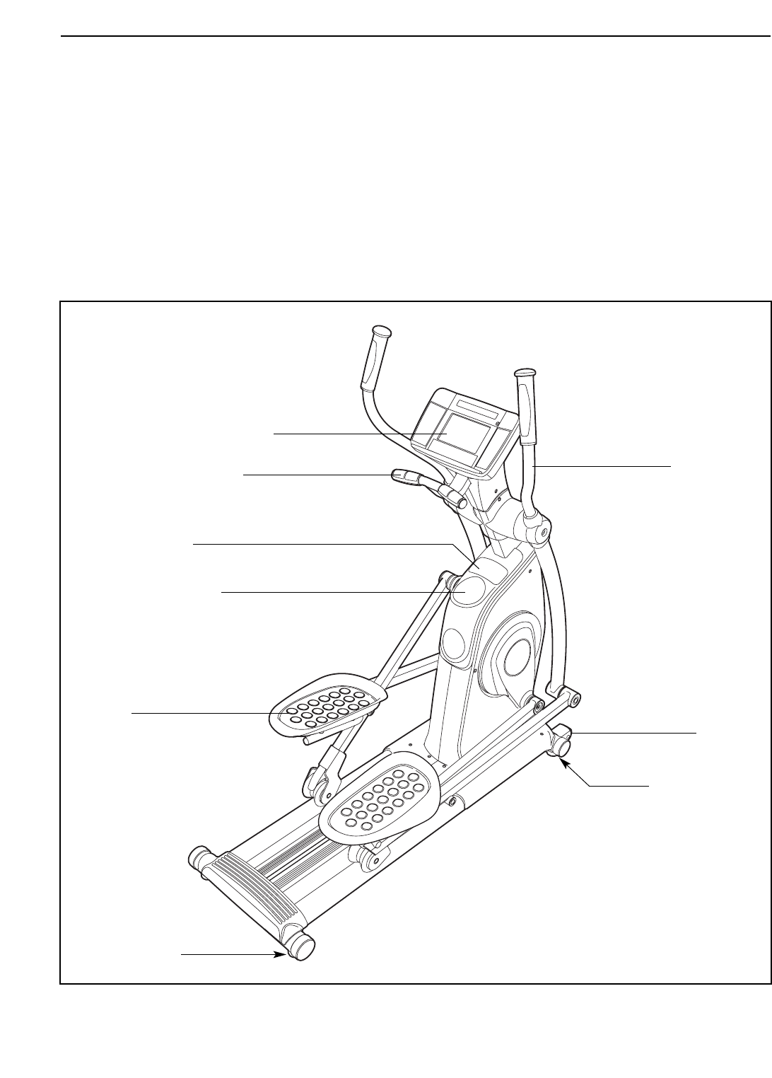
Before reading further, please familiarize yourself with
the parts that are labeled in the drawing below.
Handgrip Pulse Sensor
Wheel
Pedal
Console/Personal Television
Water Bottle Holder*
Accessory Tray
Leveling Foot
*No water bottle is included
Handlebar
Leveling Foot
5
ASSEMBLY
To hire an authorized service technician to assemble the elliptical exerciser, call 1-800-445-2480.
Assembly requires two persons. Place all parts of the elliptical exerciser in a cleared area and remove the
packing materials. Do not dispose of the packing materials until assembly is completed. In addition to the
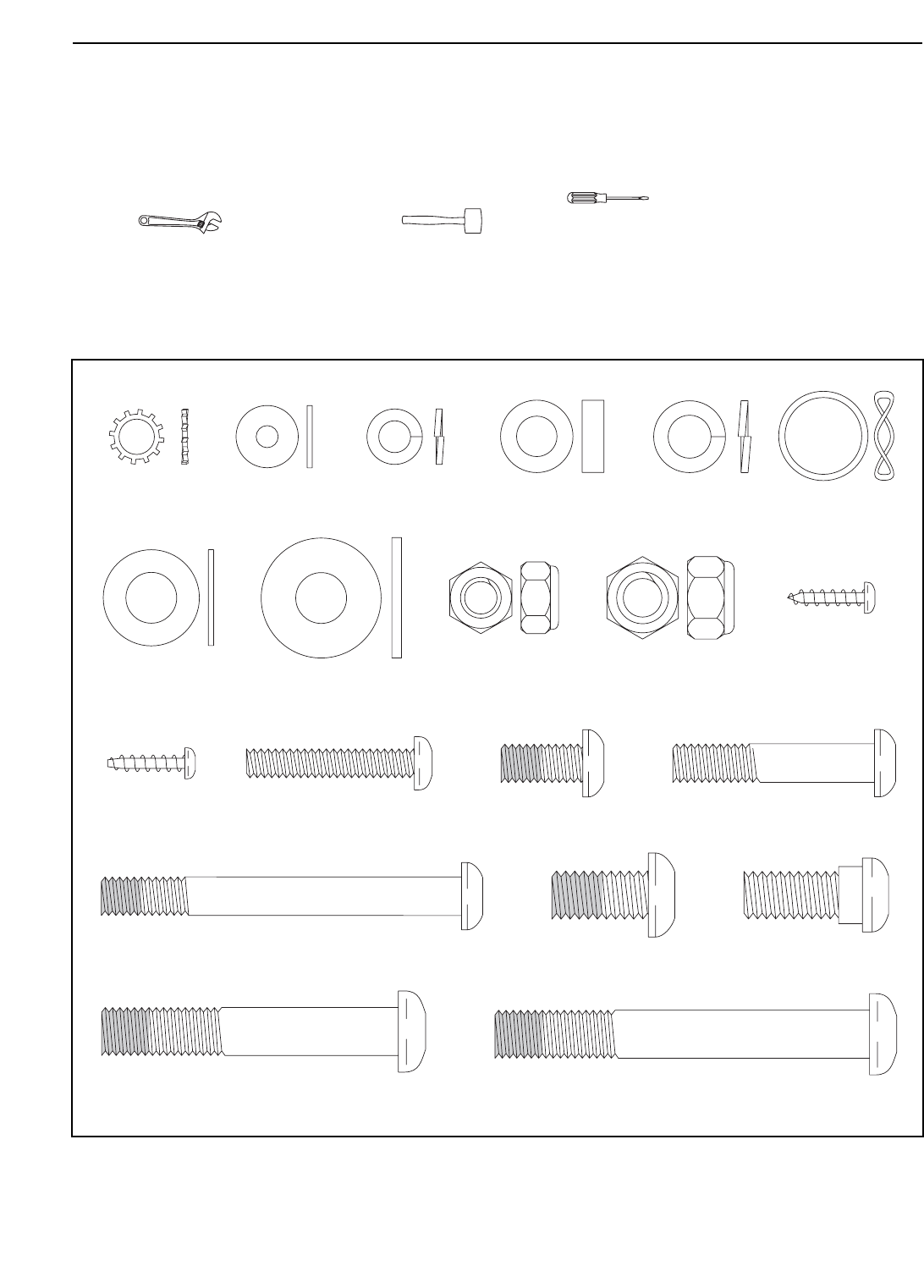
included hex keys, assembly requires a Phillips screwdriver , an adjustable
wrench , and a rubber mallet .
As you assemble the elliptical exerciser, use the drawings below to identify small parts. The number in parentheses
below each drawing is the key number of the part, from the PART LIST near the end of this manual. The number
following the parentheses is the quantity needed for assembly. Note: Some small parts may have been pre-
assembled. If a part is not in the hardware kit, check to see if it has been preassembled.
M4 x 16mm
Self-tapping
Screw (79)–16
M8 x 42mm Bolt
(71)–4
M10 x 20mm x
1mm Washer
(81)–2
M4 x 16mm
Screw (86)–8
M6 x 35mm Phillips
Screw (87)–8
M6 Split
Washer (88)–8
M10 x 23mm Shoulder
Screw (80)–2
M4 x 13mm
Washer (93)–2
M10 x 25mm
Washer (94)–10
M8 Nylon
Locknut (96)–4
M10 Nylon
Locknut (97)–2
Wave Washer
(98)–8
Star Washer
(100)–3
M8 x 15mm x 4.5mm
Washer (99)–4
M8 Split
Washer (72)–4
M10 x 20mm Patch
Screw (91)–10
M8 x 16mm Patch
Screw (95)–3
M8 x 75mm Patch
Screw (107)–4
M10 x 78mm Patch Screw (90)–2
M10 x 62mm Patch Bolt (89)–2
6
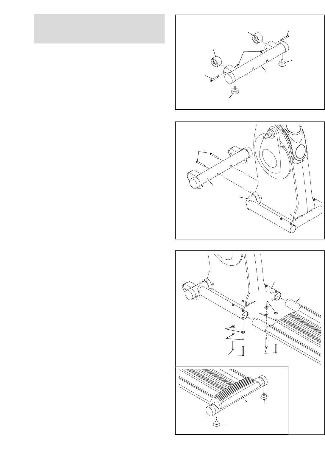
1.
Attach the two Wheels (25) to the Front Stabilizer
(35) with two M10 x 62mm Patch Bolts (89) and
two M10 Nylon Locknuts (97).
Attach two Leveling Feet (26) to the underside of
the Front Stabilizer (35).
2. Orient the Front Stabilizer (35) as shown. Have a
second person tip the Frame (2) backward.
Attach the Front Stabilizer (35) to the Frame with
two M10 x 78mm Patch Screws (90).
97
26
26
1
2
89
89
25
25
90
35
35
2
3. Position the Base (1) near the Frame (2) as
shown. See the inset drawing. Attach two
Leveling Feet (26) to the underside of the Base.
Have a second person tip the Frame (2) forward.
Insert the Base (1) into the Frame. Attach the
Base with four M8 x 75mm Patch Screws (107),
four M8 Split Washers (72), and four
M8 x 15mm x 4.5mm Washers (99).
2
1
3
1
99
72
107 107
26
26
To make assembly easier, read the
information on page 5 before you begin
assembling the elliptical exerciser.
72
99
7
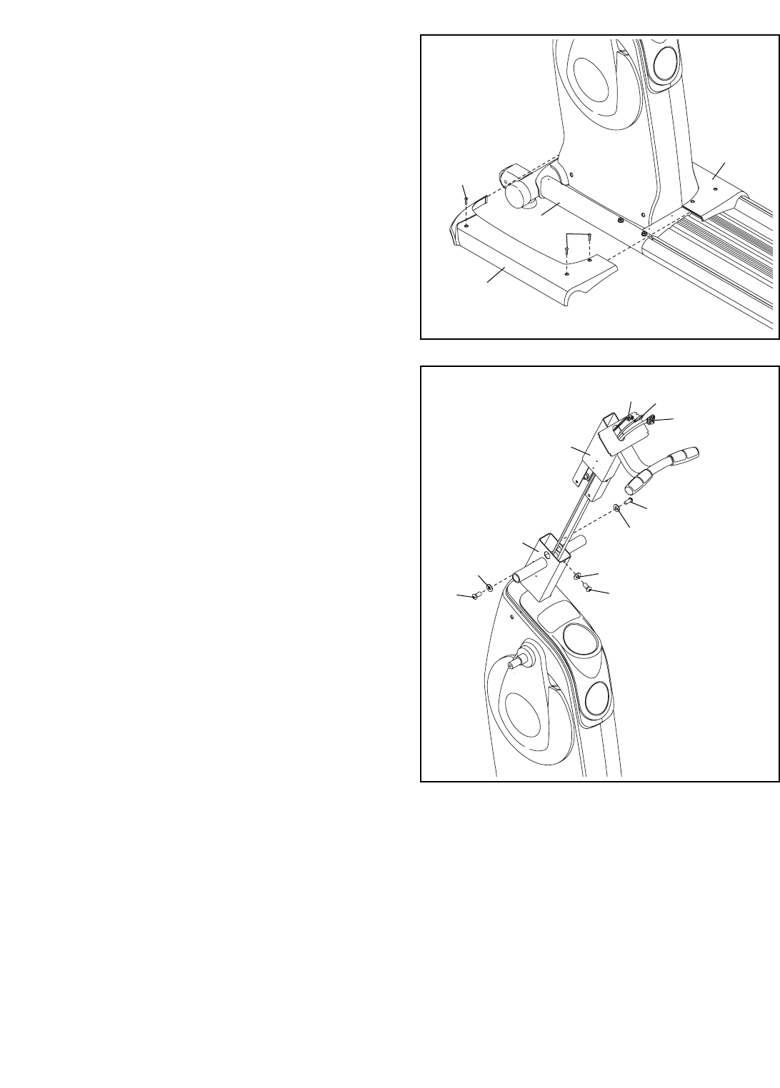
5. Have a second person hold the Upright (6) near
the Frame (2) as shown.
Pull the Wire Harness (48) and the Coaxial
Cable (109) out of the Frame (2) and insert them
upward through the Upright (6). Do not let the
Wire Harness, the Coaxial Cable, or the Pulse
Wire (110) fall into the Upright; use a piece of
tape or an elastic band to hold the wires in place
until step 13.
Insert the Upright (6) into the Frame (2). Attach
the Upright with three M8 x 16mm Patch
Screws (95) and three Star Washers (100).
Avoid pinching the Wires (48, 110) and the
Coaxial Cable (109) between the Upright and
the Frame.
4. Hook the front ends of the Frame Covers (105,
106) together. Attach each Frame Cover to the
Frame (2) with three M4 x 16mm Self-tapping
Screws (79).
4
79
79
105
2
106
5
6
95
95
95
48
109
110
100
100
100
2
Avoid pinching
the wires and
cable during
this step
8
7
11
71
8
96
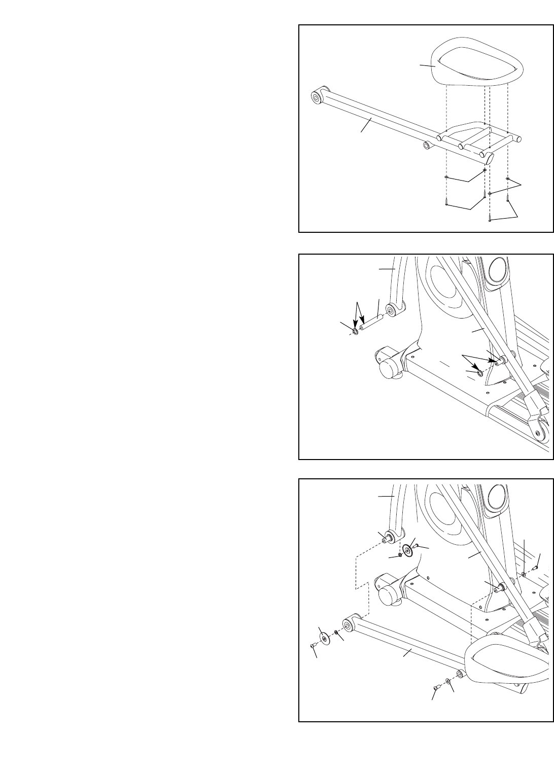
7. Identify the Left Handlebar (8), which is marked
with a “Left” sticker. Insert the Left Handlebar into
one of the Handlebar Legs (11) as shown.
Attach the Left Handlebar (8) with two
M8 x 42mm Bolts (71) and two M8 Nylon
Locknuts (96). Make sure that the Nylon
Locknuts are inside the hexagonal holes.
Assemble the Right Handlebar and the other
Handlebar Leg (not shown) in the same way.
Hexagonal
Holes
6. Orient the Left Roller Leg (12), which is marked
with a “Left” sticker, near the left Crank Arm (36)
as shown.
Apply a small amount of the included grease to
both sides of a Wave Washer (98). Slide the
Wave Washer onto the end of the left Crank
Arm (36). Next, slide the Left Roller Leg (12)
onto the Crank Arm and set the Roller (22) on
the Base (1). Attach the Left Roller Leg with an
M10 x 20mm Patch Screw (91), a Crank Axle
Cap (30), and an M10 x 25mm Washer (94).
Repeat this step to attach the Right Roller
Leg (21) to the right Crank Arm (not shown).
12
21
1
36
91
94
30
98
6
22
9
8. Attach Inner and Outer Handlebar Covers (18,
19) around the Left Handlebar (8) with three M4 x
16mm Self-tapping Screws (79) and an M4 x
13mm Washer (93). Start all three Self-tapping
Screws before tightening any of them.
Repeat this step for the Right Handlebar (not
shown).
8
79
79
93
19
8
18
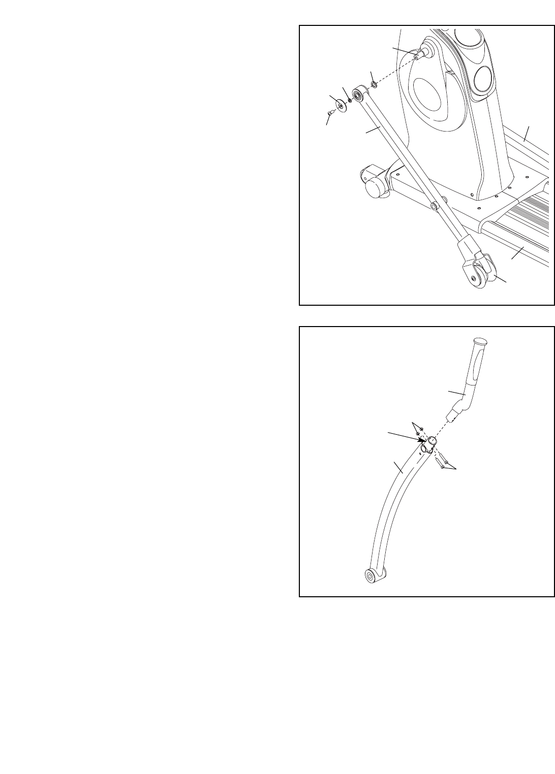
9. Apply a generous amount of grease to the
Pivot Axle (65), and insert the Pivot Axle into the
Frame (2).
Attach each Frame Cover (17) to the Frame (2)
with two M4 x 16mm Screws (86).
9
Grease 65
17
86
10. Apply a small amount of grease to both sides of
a Wave Washer (98). Slide the Wave Washer
onto the left end of the Pivot Axle (65). Next,
slide the Left Handlebar (8) onto the Pivot Axle
as shown. Attach the Left Handlebar with an
M10 x 23mm Shoulder Screw (80) and an
M10 x 20mm x 1mm Washer (81).
Repeat this step for the Right Handlebar (9).
10
98
8
9
80
81
2
65
17
Grease
10
11. Identify the Left Pedal (13) and the Left Pedal
Leg (14), which are marked with “Left” stickers,
and orient them as shown.
Attach the Left Pedal (13) to the Left Pedal
Leg (14) with four M6 x 35mm Phillips
Screws (87) and four M6 Split Washers (88).
Start all four Phillips Screws before tighten-
ing any of them.
Repeat this step to attach the Right Pedal to
the Right Pedal Leg (not shown).
11
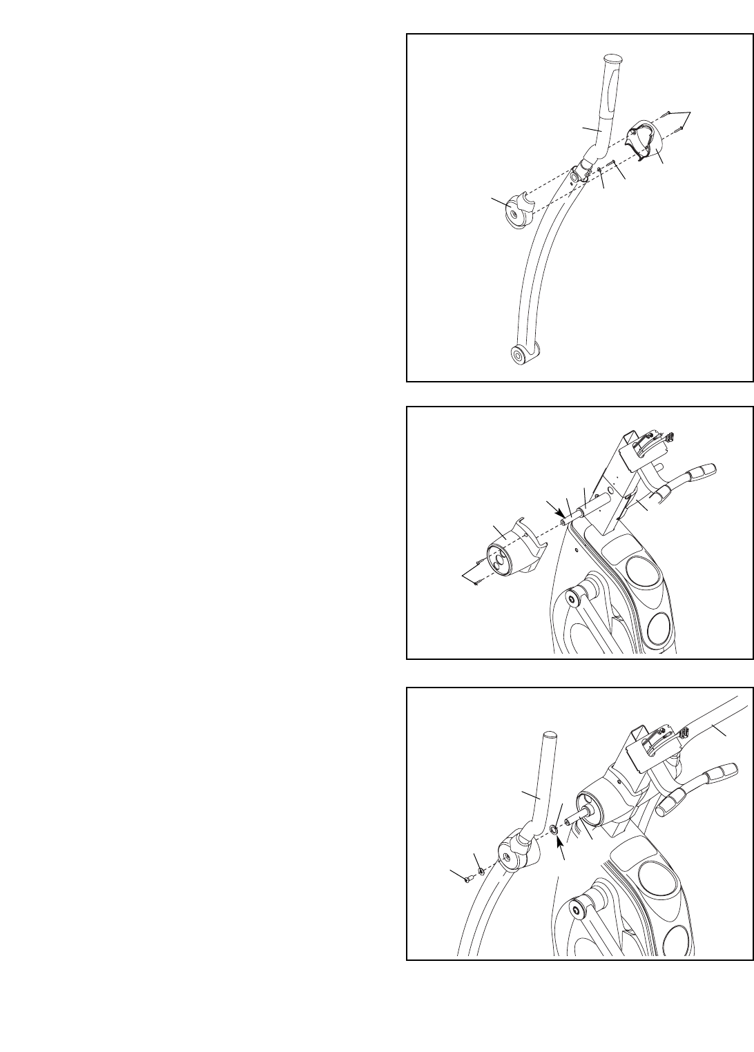
12. Apply a generous amount of grease to two Pedal
Leg Axles (32). Insert one Pedal Leg Axle into
the lower end of the Left Handlebar Leg (11).
Insert the other Pedal Leg Axle into the Left
Roller Leg (12).
Apply a small amount of grease to both sides of
two Wave Washers (98). Slide a Wave Washer
onto each Pedal Leg Axle (32).
13. Orient the Left Pedal Leg (14) as shown, and
slide it onto the Pedal Leg Axles (32). Attach the
Left Pedal Leg to the Left Handlebar Leg (11)
with two M10 x 20mm Patch Screws (91), two
Axle Caps (31), and two M10 x 25mm
Washers (94).
Attach the Left Pedal Leg (14) to the Left Roller
Leg (12) with two M10 x 20mm Patch
Screws (91) and two M10 x 25mm Washers (94);
do not overtighten the Patch Screws. The
Legs (11, 14, 12) must pivot freely.
Repeat step 12 and this step for the Right
Pedal Leg (not shown).
12
13
14
88
87
87
88
11
32
98
12
Grease
98
32
Grease
11
32
94 91
94
91
31
91 94
91
94
12
14
32
13
31
11
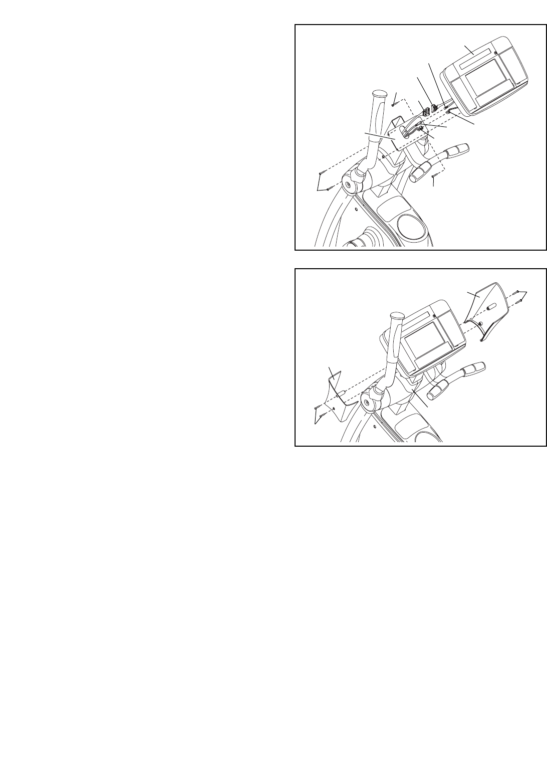
14. Have a second person hold the Console (5) near
the Upright (6) as shown. Connect the console
wire harness to the Wire Harness (48), connect
the console cable to the Coaxial Cable (109), and
connect the console pulse wire to the Pulse Wire
(110). Insert the excess wire and cable downward
into the Upright (6).
Attach the Console (5) to the Upright (6) with four
M4 x 16mm Self-tapping Screws (79). Avoid
pinching the wires and cables during this
step.
16. Make sure that all parts of the elliptical exerciser are properly tightened. Note: Some hardware may be
left over after assembly is completed. To protect the floor or carpet from damage, place a mat under the
elliptical exerciser.
Plug the power cord into the power socket at the front of the elliptical exerciser (see HOW TO PLUG IN THE
POWER CORD on page 13). IMPORTANT: If the elliptical exerciser has been exposed to cold tempera-
tures, allow it to warm to room temperature before plugging in the power cord. If you do not do this,
the console displays or other electronic components may become damaged.
14 5
79 48
Console Cable
Console
Pulse Wire
109
110
79
79
Console Wire Harness
15. Attach the Left and Right Upright Covers (10, 64)
to the Upright (6) with four M4 x 16mm
Screws (86).
10
86
86
64
15
Avoid pinching
the wires and
cable during
this step
6
6

12
HOW TO CONNECT A 75 OHM CATV CABLE
1. Connect a 75 ohm
CATV cable to the 75
ohm terminal on the
elliptical exerciser
frame.
HOW TO CONNECT AN EXTERNAL SOURCE
USING A CATV CABLE
1. Connect one end of a 75 ohm CATV cable to the
video output jack on your external source.
2. Plug in the power cord of your external source.
See your external source’s user’s manual for prop-
er grounding instructions.
3. Connect the 75 ohm CATV cable to the 75 ohm
terminal on the elliptical exerciser frame.
HOW TO CONNECT A DVD PLAYER OR VCR
USING THE AUDIO/VIDEO INPUT JACK
Plug one end of an RCA component video cable into
your DVD player or VCR, and plug the other end into
the audio/video input jack on the back of the console.
75 Ohm Terminal
75 Ohm CATV Cable
Before operating the television, you must connect a 75 ohm CATV cable to the 75 ohm terminal on the
elliptical exerciser or a VCR or DVD player to the audio/video input jack. Note: Use a CATV cable to connect
to an external source such as a cable box, analog cable, satellite TV box, or VCR. No CATV cable or RCA com-
ponent video cable is included.
13
HOW TO USE THE ELLIPTICAL EXERCISER
HOW TO PLUG IN THE POWER CORD
Plug one end of the included power supply into the
jack on the front of the elliptical exerciser. Plug the
other end of the power supply into an appropriate out-
let that is properly installed in accordance with all local
codes and ordinances.
HOW TO MOVE THE ELLIPTICAL EXERCISER
Due to its size and weight, moving the elliptical
exerciser requires two persons. Stand in front of
the elliptical exerciser, hold the upright, and place one
foot against one of the front wheels. Pull on the
upright and have a second person lift the base until
the elliptical exerciser will roll on the front wheels.
Carefully move the elliptical exerciser to the desired
location, and then lower it to the floor.
HOW TO LEVEL THE ELLIPTICAL EXERCISER
If the elliptical exerciser rocks slightly on your floor
during use, turn one or both of the leveling feet
beneath the base or beneath the front stabilizer until
the rocking motion is eliminated.
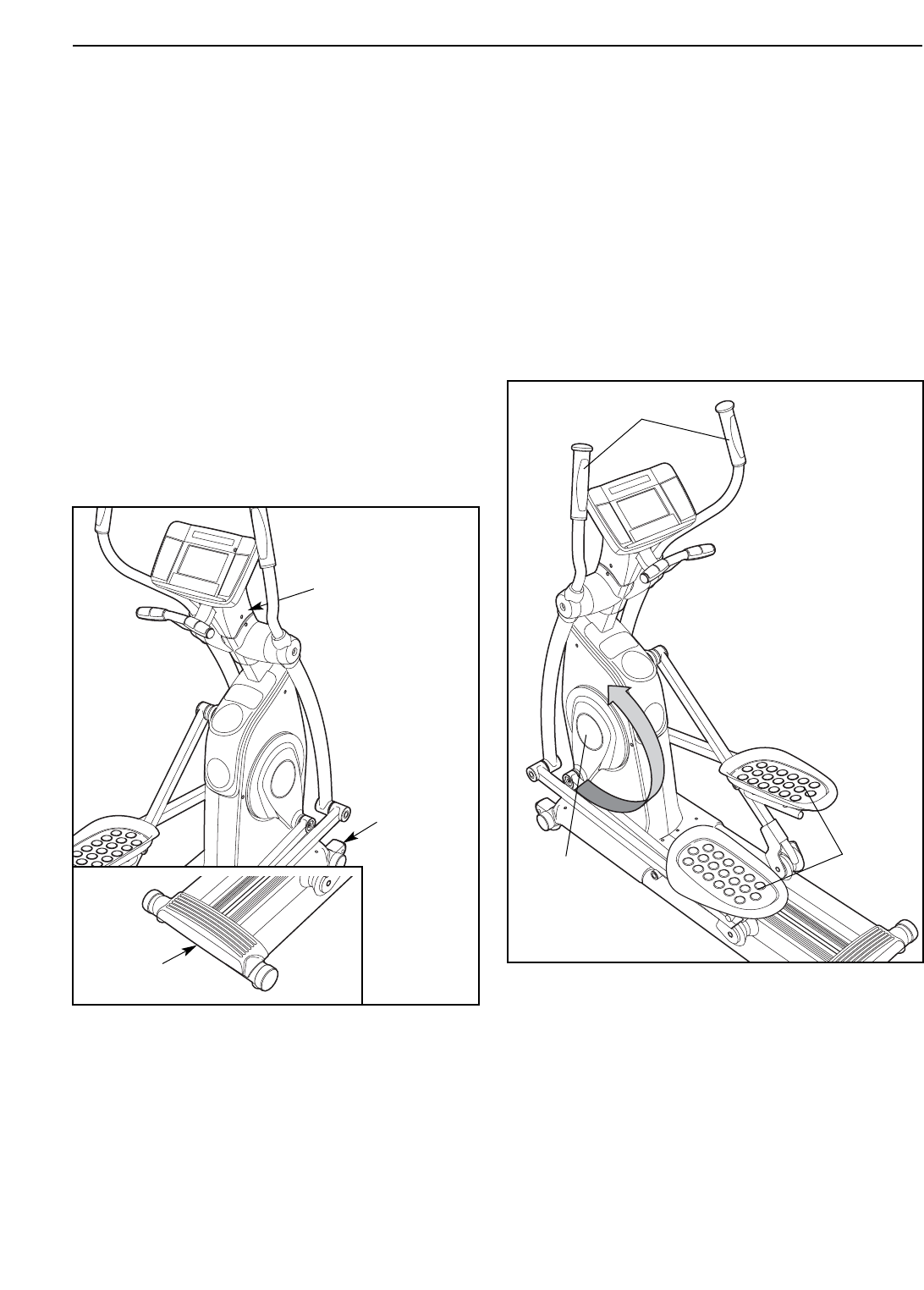
HOW TO EXERCISE ON THE ELLIPTICAL
EXERCISER
To mount the elliptical exerciser, hold the handlebars
and step onto the pedal that is in the lowest position.
Then, step onto the other pedal. Push the pedals until
they begin to move with a continuous motion. Note:
The crank arm covers can turn in either direction.
It is recommended that you turn the crank arm
covers in the direction shown by the arrow below;
however, for variety, you can turn the crank arm
covers in the opposite direction.
To dismount the elliptical exerciser, wait until the ped-
als come to a complete stop. Note: The elliptical
exerciser does not have a free wheel; the pedals
will continue to move until the flywheel stops.
When the pedals are stationary, step off the higher
pedal first. Then, step off the lower pedal.
Pedals
Crank Arm
Cover
Handlebars
Place
your foot
here
Pull on
upright
Lift here
14
FEATURES OF THE CONSOLE
The advanced console offers an array of features
designed to make your workouts more effective and
enjoyable. When you use the manual mode of the con-
sole, you can change the resistance of the pedals with
the touch of a button. While you exercise, the console
will display continuous exercise feedback. You can
also measure your heart rate using the handgrip pulse
sensor.
The console also features twenty preset programs.
Each program automatically changes the resistance of
the pedals and prompts you to vary your pedaling
pace as it guides you through an effective workout.
Choose among fitness, performance, and weight loss
programs for a targeted workout.
The console also offers two heart rate programs that
automatically control the resistance of the pedals and
prompt you to maintain a constant pedaling pace to
keep your heart rate near target heart rate settings dur-
ing your workouts.
In addition, the console offers two custom programs
that allow you to create your own workout programs
and store them in memory for future use.
Whether you use the manual mode or a program, you
can enjoy the personal television while you get in
shape. You can even connect your DVD player or VCR
to the personal television.
The console also features an information mode that
allows you to adjust the television screen settings and
to set channels into the television’s memory.
To use the manual mode of the console, follow the
steps beginning on page 15. To use a preset pro-
gram, see page 17. To use a heart rate program,
see page 18. To create a custom program, see
page 19. To use a custom program, see page 20.
To operate the personal television, see page 21.
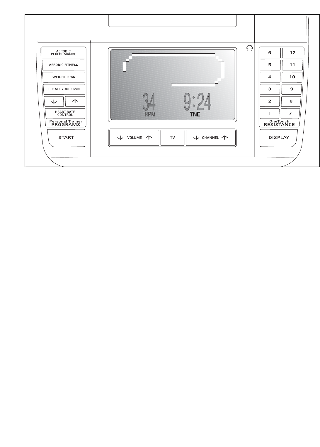
CONSOLE DIAGRAM

15
HOW TO USE THE MANUAL MODE
Note: If there is a sheet of clear plastic on the face
of the console, remove the plastic.
1. Begin pedaling or press any button on the
console to turn on the console.
A moment after you begin pedaling or press a
button, the screen will light.
2. Select the manual mode.
Each time you turn on the console, the manual
mode will be selected. If you have selected a pro-
gram, reselect the manual mode by pressing any
of the program buttons repeatedly until a track
appears in the center of the screen.
3. Change the resistance of the pedals as
desired.
As you pedal, change the resistance of the ped-
als by pressing any of the OneTouch Resistance
buttons numbered 1 through 12. Note: After you
press the buttons, it will take a moment for the
pedals to reach the selected resistance level.
4. Follow your progress with the display.
As you exercise, the screen can display the fol-
lowing exercise information:
• The elapsed time. Note: When you select a
preset program or the second heart rate pro-
gram, the screen will show the time remaining
in the program instead of the elapsed time.
• The distance you have pedaled, in total revolu-
tions.
• Your pedaling pace in revolutions per minute
(rpm).
• The approximate number of calories you have
burned.
• The resistance level of the pedals each time the
resistance changes.
• Your heart rate when you use the handgrip
pulse sensor (see step 5 on page 16).
When you select
the manual mode,
a track represent-
ing 1/4 mile will
appear on the
screen. As you
exercise, seg-
ments will appear
in succession around the track until the entire
track appears. The track will then disappear and
the segments will again begin to appear in succes-
sion
When the television is off, you can press the
Display button repeatedly to view either time and
pace information or to view all exercise informa-
tion on the screen.
When the television is on, you can display exer-
cise information on the right side or the bottom of
the screen. Or, you can turn off the exercise infor-
mation while you watch the television. Press the
Display button repeatedly to select the desired
display mode.

16
5. Measure your heart rate if desired.
If there are
sheets of clear
plastic on the
metal contacts
on the handgrip
pulse sensor,
remove the plas-
tic. To measure
your heart rate,
hold the handgrip
pulse sensor with your palms resting against the
metal contacts. Avoid moving your hands or
gripping the contacts too tightly.
When your pulse is detected, your heart rate will
appear on the screen. For the most accurate
heart rate reading, hold the contacts for at least 15
seconds. Note: If you continue to hold the hand-
grip pulse sensor, the screen will show your heart
rate for up to 30 seconds.
If the screen does not show your heart rate, make
sure that your hands are positioned as described.
Be careful not to move your hands excessively or
to squeeze the metal contacts too tightly. For
optimal performance, clean the metal contacts
using a soft cloth; never use alcohol, abrasives,
or chemicals to clean the contacts.
6. When you are finished exercising, the console
will turn off automatically.
If the pedals do not move for several seconds, a
tone will sound and the console will pause. The
time will also flash in the display. If the pedals do
not move for several minutes and the buttons are
not pressed, the console will turn off and the dis-
play will be reset. Note: If the console does not
turn off after several minutes, the console is in
the “demo” mode. See HOW TO USE THE
INFORMATION MODE on page 22 and turn off
the demo mode.
Contacts
17
HOW TO USE A PRESET PROGRAM
1. Begin pedaling or press any button on the
console to turn on the console.
A moment after you begin pedaling or press a
button, the screen will light.
2. Select a preset program.
To select one of the 20 preset programs, press
the Aerobic Performance button, the Aerobic
Fitness button, or the Weight Loss button repeat-
edly until the desired program appears on the
screen.
When a pre-
set program
is selected, a
diagram of
the resistance
settings for
the program
will appear on the screen. The arrow below the
diagram will indicate your progress during the
program. In addition, the screen will show the
total program time, the maximum pace setting for
the program, and the maximum resistance setting
for the program.
3. Press the Start button or begin pedaling to
start the program.
Each program is divided into 20, 30, or 45 one-
minute segments. One resistance level and one
target pace setting are programmed for each seg-
ment. Note: The same resistance and/or target
pace setting may be programmed for consecutive
segments. The resistance level for the current
segment will be indicated by the height of the dia-
gram above the arrow.
When only three seconds remain in the first seg-
ment of the program, a series of tones will sound.
If the resistance is about to change, the resis-
tance level will appear on the screen to alert you.
When the first segment ends, the arrow below the
diagram will move one position to the right.
The pedals will then automatically adjust to the
resistance level for the second segment.
As you exercise, you will be prompted to keep
your pedaling pace near the target pace setting
for the current segment. When the color of the
RPM display on the screen is white or blue,
increase your pace. When the RPM display is yel-
low or pink, decrease your pace. When the RPM
display is green, maintain your current pace.
Important: The target pace settings are intend-
ed only to provide motivation. Your actual
pace may be slower than the target pace set-
ting. Make sure to exercise at a pace that is
comfortable for you.
If the resistance level for the current segment is
too high or too low, you can manually override the
setting by pressing the OneTouch Resistance but-
tons. However, when the current segment of the
program ends, the pedals will automatically adjust
to the resistance level for the next segment.
The program will continue in this way until the
arrow reaches the right end of the diagram. To
stop the program at any time, stop pedaling. A
tone will sound and the time will flash in the dis-
play to indicate that the program is paused. To
restart the program, simply resume pedaling.
4. Follow your progress with the display.
See step 4 on page 15.
5. Measure your heart rate if desired.
See step 5 on page 16.
6. When you are finished exercising, the console
will turn off automatically.
See step 6 on page 16.
DiagramArrow

18
HOW TO USE A HEART RATE PROGRAM
1. Begin pedaling or press any button on the
console to turn on the console.
A moment after you turn on the console, the
screen will light.
2. Select a heart rate program.
To select one of the two heart rate programs,
press the Heart Rate Control button once or twice
until the desired program appears on the screen.
If you select the first heart rate program, a
track and the target heart rate setting (bpm) for
the program will appear on the screen.
If you select the second heart rate program,
the maximum target heart rate setting (bpm) and
a diagram of the target heart rate settings for the
program will appear on the screen. The arrow
below the diagram will indicate your progress.
3. Enter a target heart rate setting.
If you select the first heart rate program, the
target heart rate setting (bpm) for the program will
appear on the screen. Press the increase and
decrease buttons above the Heart Rate Control
button to change the target heart rate setting, if
desired. Note: The same target heart rate setting
will be programmed for the entire program. See
EXERCISE INTENSITY on page 25 for heart
rate guidelines.
If you select the second heart rate program,
the maximum target heart rate setting of the pro-
gram will appear on the screen. Press the
increase and decrease buttons above the Heart
Rate Control button to change the maximum tar-
get heart rate setting, if desired. Note: If you
change the maximum target heart rate setting,
the intensity level of the entire program will
change. See EXERCISE INTENSITY on page 25
for heart rate guidelines.
4. Hold the handgrip pulse sensor.
It is not necessary to hold the handgrip pulse
sensor continuously during a heart rate program;
however, you should hold the handgrip pulse sen-
sor frequently for the program to operate properly.
Each time you hold the handgrip pulse sen-
sor, keep your hands on the metal contacts
for at least 30 seconds.
5. Press the Start button or begin pedaling to
start the program.
First heart rate control program—The same
target heart rate setting is programmed for all
segments of this program.
Second heart rate program—This program is
divided into 30 one-minute segments. One target
heart rate setting is programmed for each seg-
ment. Note: The same target heart rate setting
may be programmed for consecutive segments.
The target heart rate setting for the first segment
will be indicated by the height of the program dia-
gram. When the first segment ends, the arrow
below the diagram will move one position to the
right.
The program will continue in this way until the
arrow reaches the right end of the program dia-
gram. To stop the program at any time, stop ped-
aling. A tone will sound and the time will flash in
the display to indicate that the program is
paused. To restart the program, simply resume
pedaling.

19
Both heart rate programs—As you pedal, the
console will regularly compare your heart rate to
the target heart rate setting. If your heart rate is
too far below or above the target heart rate setting,
the resistance of the pedals will automatically
increase or decrease to bring your heart rate clos-
er to the target heart rate setting.
You will also be prompted to pedal at a steady
pace. When the color of the RPM display on the
screen is white or blue, increase your pace.
When the RPM display is yellow or pink,
decrease your pace. When the RPM display is
green, maintain your current pace. Important:
Make sure to exercise at a pace that is com-
fortable for you.
Note: You can manually override the resistance
level setting; however, if you change the resis-
tance level, you might not maintain the target
heart rate. Also, when the console compares your
heart rate to the target heart rate setting, the
resistance of the pedals may automatically
increase or decrease to bring your heart rate
closer to the target heart rate setting.
6. Follow your progress with the display.
See step 4 on page 15.
7. Measure your heart rate if desired.
See step 5 on page 16.
8. When you are finished exercising, the console
will turn off automatically.
See step 6 on page 16.
HOW TO CREATE A CUSTOM PROGRAM
1. Begin pedaling or press any button on the
console to turn on the console.
A moment after you turn on the console, the
screen will light.
2. Select a custom program.
To select a custom program, press the Create
Your Own button once or twice until the desired
custom program appears on the screen.
3. Press the Start button or begin pedaling to
start the program, and program the desired
settings.
Each custom program is divided into 40 one-
minute segments. You can program one resis-
tance level and one target pace for each seg-
ment.
To program a resistance level for the first seg-
ment, simply adjust the resistance of the pedals
by pressing the OneTouch Resistance buttons. To
program a target pace for the first segment, sim-
ply pedal at the desired pace.
At the end of the first segment, the program will
store the current resistance level and your current
pace in memory. Program a resistance level and
a target pace for the second segment as
described above.
Continue exercising for up to forty minutes. Press
the Create Your Own button when you are fin-
ished with your workout. The program you creat-
ed will then be stored in memory. Note: If your
workout is less than forty minutes long, any remain-
ing segments in the program will be stored with the
last programmed resistance level and target pace.
4. When the program is finished, the console will
turn off automatically.
See step 6 on page 16.

20
HOW TO USE A CUSTOM PROGRAM
1. Begin pedaling or press any button on the
console to turn on the console.
A moment after you turn on the console, the
screen will light.
2. Select a custom program.
To select a custom program, press the Create
Your Own button once or twice until the desired
custom program appears on the screen.
3. Press the Start button or begin pedaling to
start the program.
Each custom program is divided into 40 one-
minute segments. One resistance level and one
target pace setting are programmed for each seg-
ment.
At the end of each segment, the resistance level
will appear on the screen. The resistance of the
pedals will then automatically change to the resis-
tance level programmed for the next segment.
As you exercise, you will be prompted to keep
your pedaling pace near the target pace setting
for the current segment. When the color of the
RPM display on the screen is white or blue,
increase your pace. When the RPM display is yel-
low or pink, decrease your pace. When the RPM
display is green, maintain your current pace.
To stop the program at any time, stop pedaling. A
tone will sound to indicate that the program is
paused. To restart the program, simply resume
pedaling.
4. Change the program if desired.
If desired, you can change the program while
using it. To change the resistance level for the
current segment, simply press the OneTouch
Resistance buttons. At the end of the current seg-
ment, the new resistance level will be stored in
memory. To change the target pace for the cur-
rent segment, simply change your pedaling
pace. At the end of the current segment, your
pace will be stored in memory. You can continue
exercising and changing the program for up to
forty minutes.
5. Follow your progress with the display.
See step 4 on page 15.
6. Measure your heart rate if desired.
See step 5 on page 16.
7. When the program is finished, the console will
turn off automatically.
See step 6 on page 16.

21
HOW TO OPERATE THE PERSONAL TELEVISION
IMPORTANT: Before operating the television, you
must connect a 75 ohm CATV cable to the 75 ohm
terminal on the elliptical exerciser or a VCR or DVD
player to the audio/video input jack; or a personal
audio/video player to the audio/video jack below
the television on the console. See page 12 for
instructions.
Follow the steps below to operate the television.
1. Begin pedaling or press any button on the con-
sole to turn on the console.
When you turn on the console, the console mode
will be automatically selected and the word
CONSOLE will appear on the screen.
2. Press the TV button to turn on the television.
To turn on the television, press the TV button
once. The word TUNER will appear on the screen.
3. Press the Channel buttons to select the
desired cable channel.
Note: Complete this step only if you are using ana-
log cable. Otherwise, change channels through an
external source such as your cable box or your
VCR.
When you turn on the television, the screen will
show the last cable channel that was selected. To
select a different channel, press the Channel but-
tons. The selected cable channel number will
appear on the screen for a few seconds. Note:
The television is equipped with a channel memo-
rizing function that allows you to go directly from
the current channel to the next channel saved in
memory. Before channels can be selected in this
way, they must be saved in the television’s memo-
ry. See HOW TO USE THE INFORMATION
MODE on page 22.
4. Press the Volume buttons to adjust the vol-
ume.
When you press either Volume button, the volume
level indicator will appear on the screen for a few
seconds.
To use earphones or headphones (not included),
plug them into the headphone jack on the console.
5. When you are finished using the television,
press the TV button.
To turn off the television, press the TV button
repeatedly until the word CONSOLE appears on
the screen.
HOW TO OPERATE A DVD PLAYER OR VCR
IMPORTANT: Before operating a DVD player or
VCR, you must connect a CATV cable or an RCA
component video cable to the console. See page
12 for instructions.
1. Begin pedaling or press any button on the con-
sole to turn on the console.
When you turn on the console, the console mode
will be automatically selected and the word
CONSOLE will appear on the screen.
2. Select the appropriate viewing mode.
To operate a DVD player or VCR connected with a
CATV cable, press the TV button repeatedly until
the word TUNER appears on the screen.
To operate a DVD player or VCR connected with a
component video cable, press the TV button
repeatedly until the word AV1 appears on the
screen. Then, press the play button on your DVD
player or VCR.
3. Press the Volume buttons to adjust the
volume.
When you press either Volume button, the volume
level indicator will appear on the screen for a few
seconds.
To use earphones or headphones (not included),
plug them into the headphone jack on the console.
4. When you are finished using the television,
press the TV button.
To turn off the television, press the TV button
repeatedly until the word CONSOLE appears on
the screen.

22
HOW TO USE THE INFORMATION MODE
1. Press and hold down the TV button and adjust
the television settings if desired.
Press and hold down the TV button for several
seconds to access the information mode. The
brightness level indicator will appear on the televi-
sion screen. Press the Volume buttons to adjust
the brightness setting if desired.
Next, press the Channel buttons until the contrast,
color, sharpness, or hue level indicator appears.
Adjust the settings, if desired, by pressing the
Volume buttons.
Note: The elliptical exerciser features a demo
mode that is intended to be used only while the
elliptical exerciser is displayed in a store. When
the demo mode is turned on, the console will not
turn off automatically when the elliptical exerciser
is not in use. Press the Start button repeatedly to
turn off or turn on the demo mode. The words
DEMO OFF or DEMO ON will appear at the top of
the screen to indicate whether the mode is turned
on or off.
2. Press the TV button again and add or delete
cable channels.
Note: Complete this step only if you are using ana-
log cable.
After all valid cable channels available in your area
have been saved into the television’s memory (see
step 4 on this page), you can manually add chan-
nels or delete unwanted channels.
To add or delete a cable channel, first press the
Channel buttons until the desired channel number
appears on the screen. Then, press the Volume
increase button to add the channel, or the Volume
decrease button to delete the channel. Continue
this process until you have added all desired chan-
nels and deleted all unwanted channels.
3. Press the TV button again and select a cable
connection.
After you press the TV button, press the Volume
increase button to select the Standard Cable set-
ting, the Channel decrease button to select the
Cable IRC setting, or the Channel increase button
to select the Cable HRC setting. Note: If you have
connected a CATV cable, one of the three Cable
settings should be selected; try all three Cable set-
tings, if necessary, to find the optimal setting.
4. Press the TV button again and save cable
channels into the television’s memory.
When you press the TV button, the television will
begin scanning all the cable channels available in
your area. When no signal is detected on a cable
channel, the channel will be skipped. When a
cable signal is detected, the channel will be saved
into memory and the next channel will be selected.
This process will continue until the highest channel
number is reached. Do not exit the information
mode while the television is scanning for chan-
nels. Note: If you are viewing channels through an
external source such as a cable box or a VCR, the
television will save only the channel used by the
external source.
5. When you are finished using the information
mode, press the Display button.
To exit the information mode at any time (except
while the television is scanning channels), press
the Display button.
23
Inspect and tighten all parts of the elliptical exerciser
regularly. Replace any worn parts immediately.
To clean the elliptical exerciser, use a damp cloth and
a small amount of mild soap. Make sure to regularly
clean the rollers and the track on which the rollers
ride. Important: To avoid damage to the console,
keep liquids away from the console and keep the
console out of direct sunlight.
HANDGRIP PULSE SENSOR TROUBLESHOOTING
If the console does not display your heart rate when
you hold the handgrip pulse sensor, or if the displayed
heart rate appears to be too high or too low, see step
5 on page 16.
HOW TO LEVEL THE ELLIPTICAL EXERCISER
If the elliptical exerciser rocks slightly on your floor
during use, see HOW TO LEVEL THE ELLIPTICAL
EXERCISER on page 13.
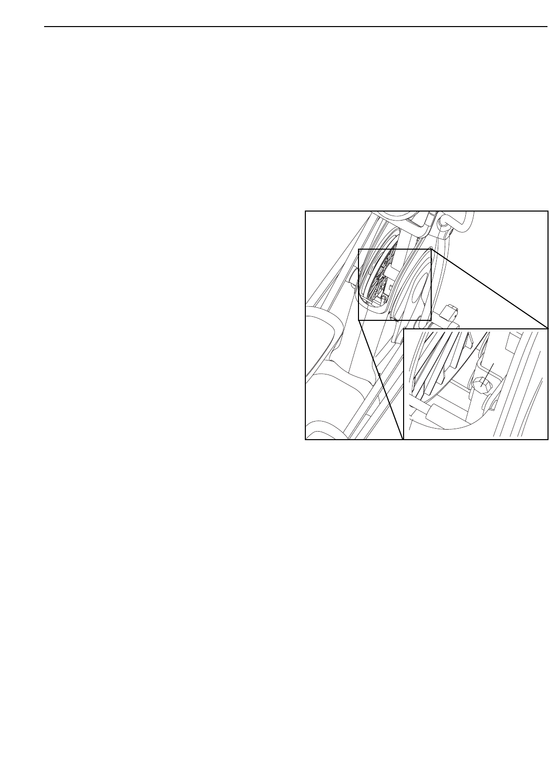
HOW TO ADJUST THE DRIVE BELT
If the pedals slip while you are pedaling, even while
the resistance is adjusted to the highest setting, the
drive belt may need to be adjusted. To adjust the
drive belt, first remove the screws from the left and
right side shields (not shown). Note: There are two
different sizes of screws in the side shields; be sure to
note the location of each screw. Then, gently pull the
side shields apart and remove the convenience tray.
Next, locate the Idler Screw (68) and loosen it one
half turn. Step onto the elliptical exerciser and move
the pedals. If the pedals continue to slip, turn the Idler
Screw another half turn and test the pedals again.
Continue in this way until the pedals no longer slip.
Then, replace the convenience tray and reattach the
side shields.
MAINTENANCE AND TROUBLESHOOTING
68

24
TELEVISION TROUBLESHOOTING
You can solve most television problems by following
the steps below. Find the symptom that applies, and
follow the steps listed. If you need further assistance,
please see the front cover of this manual.
PROBLEM:
Television reception is poor.
SOLUTION:
a. Check for the problems listed below and follow the
applicable instructions.
• Ignition (black spots or horizontal streaks that
appear or a picture that flutters or drifts)—
Usually this is caused by interference from auto-
mobile ignition systems, neon lamps, electric
drifts, or other electric appliances. Try changing
the position of the elliptical exerciser or other
electric appliances to correct the problem. Make
sure the elliptical exerciser is plugged into its
own electrical circuit.
• Ghosts—Ghosts are caused by the television
signal following two paths—one is the direct path
and the other is reflected from tall buildings, hills,
or other objects.
• Blue Screen—If the elliptical exerciser is located
in the fringe area of a television station where
the signal is weak, the picture may be of poor
quality or a blue screen may appear.
Note: If one of these symptoms appears when the
cable from a cable company is connected, the
symptom may be caused by the local company sig-
nal reception. Contact the local cable company.
PROBLEM:
No display appears in the CONSOLE mode and no
picture appears in the TV mode.
SOLUTION:
a. Make sure that the power cord is plugged into a
properly grounded outlet. Also make sure that the
power cord is securely connected to the jack on the
front of the elliptical exerciser.
PROBLEM:
The display appears in the CONSOLE mode, but no
picture appears in the TV mode.
SOLUTION:
a. Check the following coaxial cable connections:
• make sure that the coaxial cable is properly con-
nected to a CATV cable (see page 12).
• make sure that the coaxial cable is connected to
the terminal on the front of the elliptical
exerciser.
• Make sure that the coaxial cable is connected to
the console (see step 14 on page 11).
PROBLEM:
There is no sound or picture when a DVD player or
VCR is connected to the personal television.
SOLUTION:
a. If the DVD player or VCR is connected with a CATV
cable, make sure that the TUNER mode is selected
on the console. If the DVD player or VCR is con-
nected with an RCA component video cable, make
sure that the AV1 mode is selected on the console.
b. Make sure that the CATV cable or the RCA compo-
nent video cable is connected to the correct
audio/video output terminal or jacks on the DVD
player or VCR. Refer to your DVD player or VCR
owner’s manual for detailed connection instructions.
25
These guidelines will help you to plan your exercise
program. For detailed exercise information, obtain a
reputable book or consult your physician. Remember,
proper nutrition and adequate rest are essential for
successful results.
EXERCISE INTENSITY
Whether your goal is to burn fat or to strengthen your
cardiovascular system, exercising at the proper inten-
sity is the key to achieving results. You can use your
heart rate as a guide to find the proper intensity level.
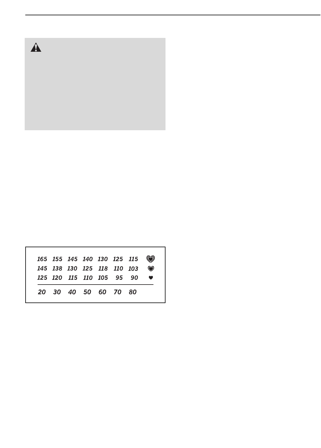
The chart below shows recommended heart rates for
fat burning and aerobic exercise.
To find the proper intensity level, find your age at the
bottom of the chart (ages are rounded off to the near-
est ten years). The three numbers listed above your
age define your “training zone.” The lowest number is
the heart rate for fat burning, the middle number is the
heart rate for maximum fat burning, and the highest
number is the heart rate for aerobic exercise.
Burning Fat—To burn fat effectively, you must exer-
cise at a low intensity level for a sustained period of
time. During the first few minutes of exercise, your
body uses
carbohydrate calories
for energy. Only after
the first few minutes of exercise does your body begin
to use stored
fat calories
for energy. If your goal is to
burn fat, adjust the intensity of your exercise until your
heart rate is near the lowest number in your training
zone. For maximum fat burning, exercise with your
heart rate near the middle number in your training
zone.
Aerobic Exercise—If your goal is to strengthen your
cardiovascular system, you must perform aerobic
exercise, which is activity that requires large amounts
of oxygen for prolonged periods of time. For aerobic
exercise, adjust the intensity of your exercise until
your heart rate is near the highest number in your
training zone.
WORKOUT GUIDELINES
Warming up—Start with 5 to 10 minutes of stretching
and light exercise. A warm-up increases your body
temperature, heart rate, and circulation in preparation
for exercise.
Training Zone Exercise—Exercise for 20 to 30 min-
utes with your heart rate in your training zone. (During
the first few weeks of your exercise program, do not
keep your heart rate in your training zone for longer
than 20 minutes.) Breathe regularly and deeply as you
exercise–never hold your breath.
Cooling down—Finish with 5 to 10 minutes of
stretching. Stretching increases the flexibility of your
muscles and helps to prevent post-exercise problems.
EXERCISE FREQUENCY
To maintain or improve your condition, complete three
workouts each week, with at least one day of rest
between workouts. After a few months of regular exer-
cise, you may complete up to five workouts each
week, if desired. Remember, the key to success is to
make exercise a regular and enjoyable part of your
everyday life.
EXERCISE GUIDELINES
WARNING: Before beginning
this or any exercise program, consult your
physician. This is especially important for
persons over the age of 35 or persons with
pre-existing health problems.
The pulse sensor is not a medical device.
Various factors may affect the accuracy of
heart rate readings. The pulse sensor is
intended only as an exercise aid in determin-
ing heart rate trends in general.
26
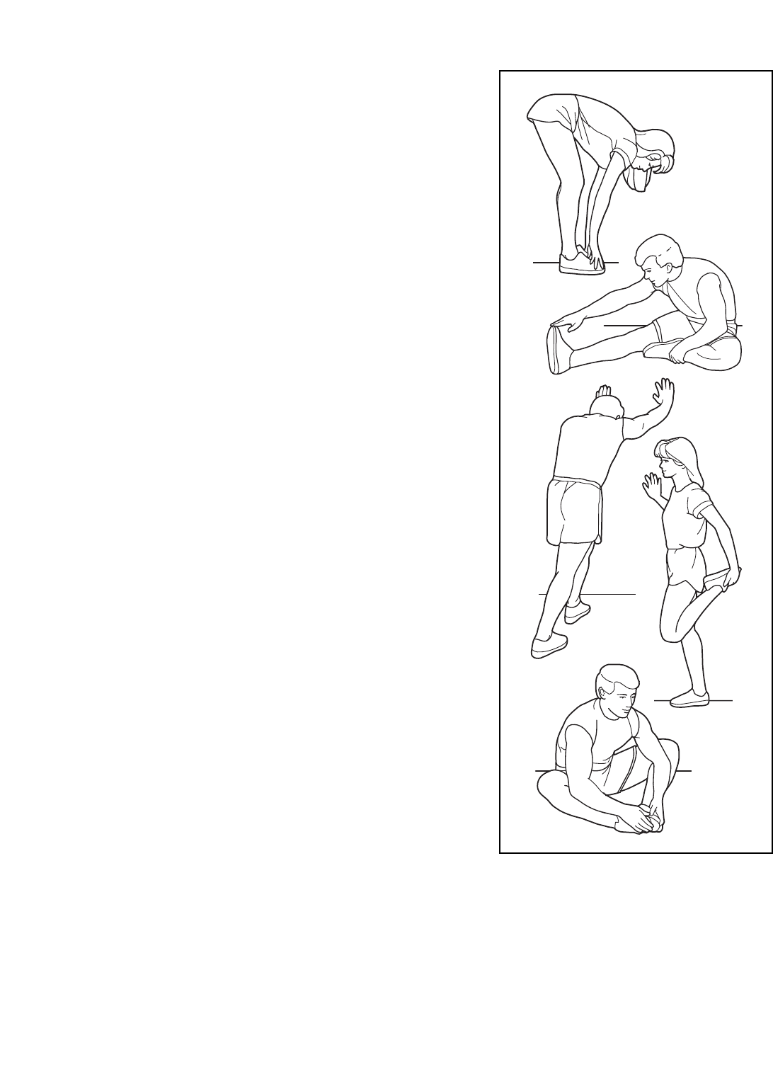
SUGGESTED STRETCHES
The correct form for several basic stretches is shown at the
right. Move slowly as you stretch—never bounce.
1. Toe Touch Stretch
Stand with your knees bent slightly and slowly bend forward
from your hips. Allow your back and shoulders to relax as you
reach down toward your toes as far as possible. Hold for 15
counts, then relax. Repeat 3 times. Stretches: Hamstrings, back
of knees and back.
2. Hamstring Stretch
Sit with one leg extended. Bring the sole of the opposite foot
toward you and rest it against the inner thigh of your extended
leg. Reach toward your toes as far as possible. Hold for 15
counts, then relax. Repeat 3 times for each leg. Stretches:
Hamstrings, lower back and groin.
3. Calf/Achilles Stretch
With one leg in front of the other, reach forward and place your
hands against a wall. Keep your back leg straight and your back
foot flat on the floor. Bend your front leg, lean forward and move
your hips toward the wall. Hold for 15 counts, then relax. Repeat
3 times for each leg. To cause further stretching of the achilles
tendons, bend your back leg as well. Stretches: Calves, achilles
tendons and ankles.
4. Quadriceps Stretch
With one hand against a wall for balance, reach back and grasp
one foot with your other hand. Bring your heel as close to your
buttocks as possible. Hold for 15 counts, then relax. Repeat 3
times for each leg. Stretches: Quadriceps and hip muscles.
5. Inner Thigh Stretch
Sit with the soles of your feet together and your knees outward.
Pull your feet toward your groin area as far as possible. Hold for
15 counts, then relax. Repeat 3 times. Stretches: Quadriceps
and hip muscles.
1
2
3
4
5

27
NOTES

28
1 1 Base
2 1 Frame
3 2 Outer Crank Arm Cover
4 2 Inner Crank Arm Cover
5 1 Console
6 1 Upright
7 2 Roller Cover
8 1 Left Handlebar
9 1 Right Handlebar
10 1 Left Upright Cover
11 2 Handlebar Leg
12 1 Left Roller Leg
13 1 Left Pedal
14 1 Left Pedal Leg
15 1 Right Pedal
16 1 Right Pedal Leg
17 2 Frame Cover
18 2 Inner Handlebar Cover
19 2 Outer Handlebar Cover
20 2 Axle Bearing
21 1 Right Roller Leg
22 2 Roller
23 2 Stabilizer Endcap
24 2 Roller Axle
25 2 Wheel
26 4 Leveling Foot
27 4 Wheel Bearing
28 1 Left Side Shield
29 1 Right Side Shield
30 2 Crank Axle Cap
31 4 Axle Cap
32 4 Pedal Leg Axle
33 8 Axle Bushing
34 4 Roller Bushing
35 1 Front Stabilizer
36 2 Crank Arm
37 1 Convenience Tray
38 2 Crank Hub
39 1 Pulley Spacer
40 1 Pulley
41 12 Axle Bushing
42 2 Pedal Leg Endcap
43 1 Crank Sleeve
44 1 Left Crank Bearing Set
45 1 Crank
46 8 Round Inner Cap
47 4 Snap Ring
48 1 Wire Harness
49 2 Base Endcap
50 1 Reed Switch/Wire
51 1 Belt
52 1 Flywheel
53 1 “C” Magnet
54 2 Outer Bearing Set
55 1 Magnet
56 1 Spring
57 1 Idler
58 1 Flywheel Pulley
59 1 Clamp
60 2 Inner Bearing Set
61 1 Motor
62 1 Resistance Cable Pulley
63 1 Resistance Cable Set
64 1 Right Upright Cover
65 1 Pivot Axle
66 2 Hub Cover
67 1 Stop Screw
68 1 Idler Screw
69 1 M8 Flange Screw
70 4 M8 x 35mm Screw
71 4 M8 x 42mm Bolt
72 4 M8 Split Washer
73 4 M4 x 12mm Flange Screw
74 8 M8 x 25mm Screw
75 2 3/8" Flange Screw
76 2 Hand Grip
77 2 Pivot Bushing
78 2 Pulse Sensor
79 37 M4 x 16mm Self-tapping Screw
80 2 M10 x 23mm Shoulder Screw
81 2 M10 x 20mm x 1mm Washer
82 1 Jack Bracket
83 4 M8 x 25mm Washer
84 1 Right Crank Bearing Set
85 10 M4 x 12mm Screw
86 10 M4 x 16mm Screw
87 8 M6 x 35mm Phillips Screw
88 8 M6 Split Washer
89 2 M10 x 62mm Patch Bolt
90 2 M10 x 78mm Patch Screw
91 10 M10 x 20mm Patch Screw
92 1 Power Supply
93 2 M4 x 13mm Washer
94 10 M10 x 25mm Washer
95 7 M8 x 16mm Patch Screw
96 6 M8 Nylon Locknut
97 2 M10 Nylon Locknut
98 8 Wave Washer
99 4 M8 x 15mm x 4.5mm Washer
100 3 Star Washer
Key No. Qty. Description Key No. Qty. Description
PART LIST—Model No. PFEL79907.1 R1207A

29
101 2 Pulse Sensor Endcap
102 1 Rear Base Cover
103 2 Side Base Cover
104 1 Center Base Cover
105 1 Left Frame Cover
106 1 Right Frame Cover
107 4 M8 x 75mm Patch Screw
108 1 M4 x 12mm Bright Screw
109 1 Coaxial Cable
110 1 Pulse Wire
111 4 M3 x 16mm Screw
* – Hex Key
* – Grease Packet
* – User’s Manual
Key No. Qty. Description Key No. Qty. Description
Note: Specifications are subject to change without notice. See the back cover of this manual for information
about ordering replacement parts. *These parts are not illustrated.
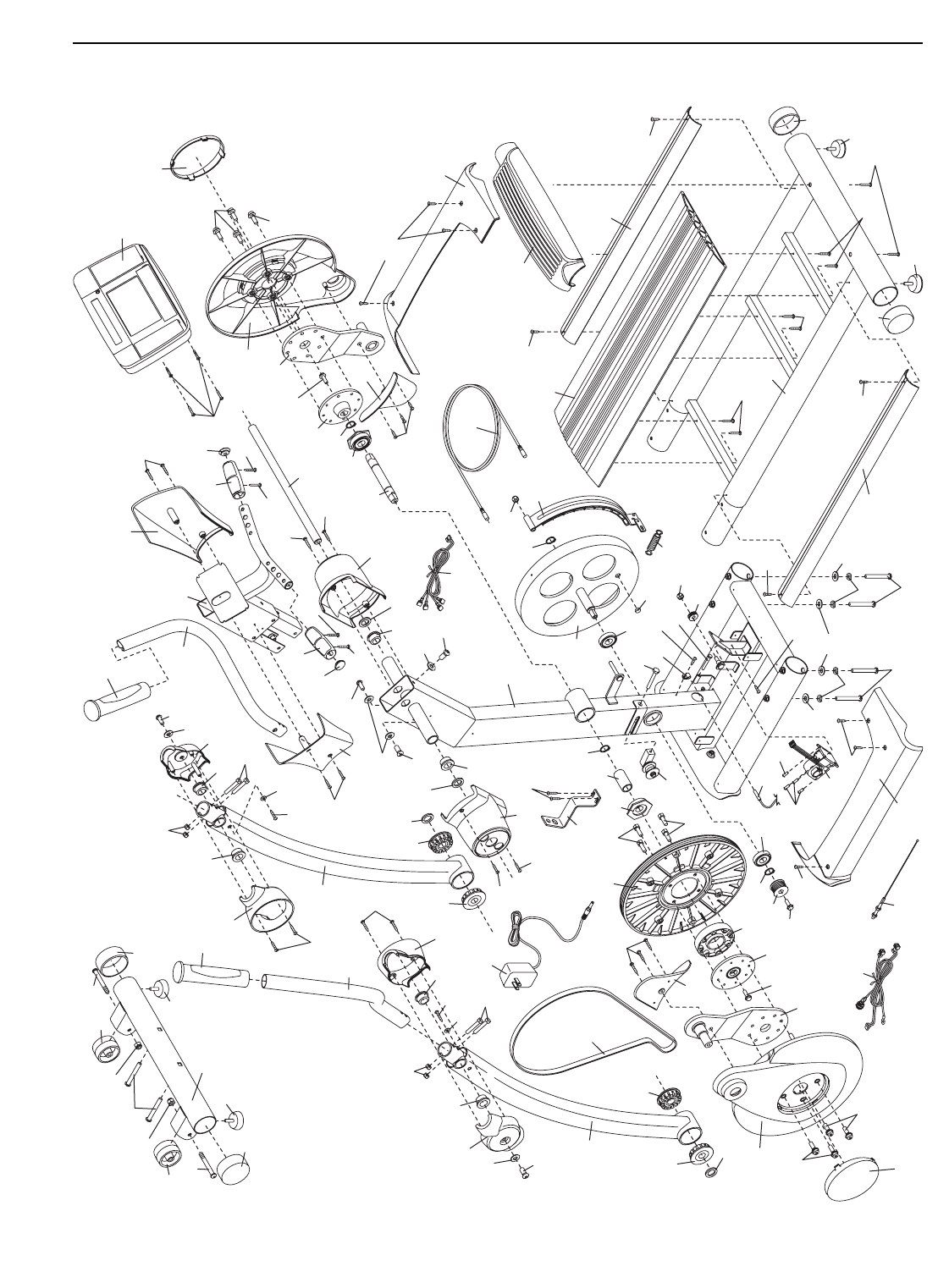
30
EXPLODED DRAWING A—Model No. PFEL79907.1 R1207A
3
4
36
38
39
43
66
74
74
75
85 70
70
3
38
84
45
47
66
36
74
74
75
52
55
47
4
85
96
68
57
23
26
26
35
25
97
89
97
89
25
23
90
11
18 19
33
33
41
41
79
79
81
80
71
96
93
98
9
53
79
59
67
20
6296
58 20
69
47
56
63
48
51
5
26
26
49
49
6
2
8
11
18
19
33
33
41
79
79
80
81 71
96
93
98
41
47
50
61
73
73
17
77
77
95
100
100
95
95
86
98
79
17
86
86
65
86
76
76
86
86
10
64
79
102
79
79
79
79
79
79
79
79
79
79
72
72
107 107
103
1
104
106
44 103
105
108
99 99
99
40
78 101
101
78
109
110
98
79
82
111
111
111
111
92
31
85
27
27
34
34
7
24
95 83
95
83
91
94
98
30
54
60
91
94
98
88
88
87
87 87
88
46
46
15
41
41
16
33
31
91
94
31
32
91
94
37
29
86
86
79
79
79
24
83
95
85
22
27
27
34
34
95
83
7
32
41
41
94
91
98
30
54
60
12
91
94
98
46
46
88
88
87 87
42
88
46
88
87
41
41
94
91
13
31
31
32
33
33
91
91
94
94
14
91
94 42
28
21
41
32
41
22
85
85
79
79
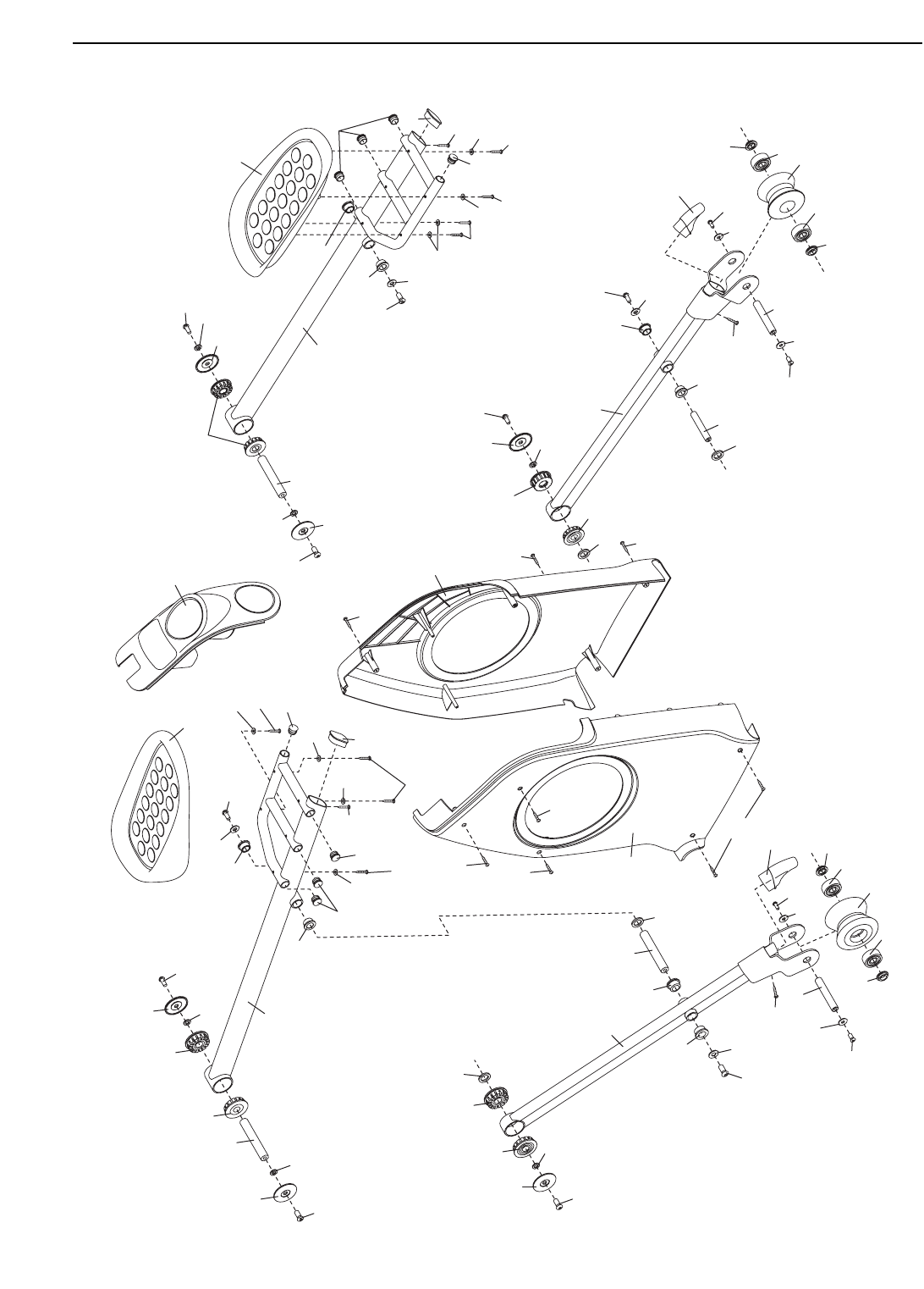
EXPLODED DRAWING B—Model No. PFEL79907.1 R1207A

Part No. 262398 R1207A Printed in China © 2007 ICON IP, Inc.
ORDERING REPLACEMENT PARTS
To order replacement parts, please see the front cover of this manual. To help us assist you, be prepared to pro-
vide the following information when contacting us:
• the model number and serial number of the product (see the front cover of the manual)
• the name of the product (see the front cover of this manual)
• the key number and description of the part(s) (see the PART LIST and the EXPLODED DRAWING near the
end of this manual)
LIMITED WARRANTY
ICON Health & Fitness, Inc. (ICON) warrants this product to be free from defects in workmanship and
material, under normal use and service conditions, for a period of one (1) year from the date of purchase.
There is a seven (7) year warranty on the resistance mechanism. There is a lifetime warranty on the
frame.
This warranty extends only to the original purchaser. ICON's obligation under this warranty is limited to
replacing or repairing, at ICON's option, the product through one of its authorized service centers. All
repairs for which warranty claims are made must be pre-authorized by ICON. If the product is shipped to
a service center, freight charges to and from the service center will be the customer’s responsibility. For
in-home service, the customer will be responsible for a minimal trip charge. This warranty does not extend
to any product or damage to a product caused by or attributable to freight damage, abuse, misuse,
improper or abnormal usage or repairs not provided by an ICON authorized service center; products used
for commercial or rental purposes; or products used as store display models. No other warranty beyond
that specifically set forth above is authorized by ICON.
ICON is not responsible or liable for indirect, special or consequential damages arising out of or in con-
nection with the use or performance of the product or damages with respect to any economic loss, loss
of property, loss of revenues or profits, loss of enjoyment or use, costs of removal or installation or other
consequential damages of whatsoever nature. Some states do not allow the exclusion or limitation of inci-
dental or consequential damages. Accordingly, the above limitation may not apply to you.
The warranty extended hereunder is in lieu of any and all other warranties and any implied warranties of
merchantability or fitness for a particular purpose is limited in its scope and duration to the terms set forth
herein. Some states do not allow limitations on how long an implied warranty lasts. Accordingly, the above
limitation may not apply to you.
This warranty gives you specific legal rights. You may also have other rights which vary from state to state.
ICON HEALTH & FITNESS, INC., 1500 S. 1000 W., LOGAN, UT 84321-9813
