Proform Pfevex799110 Le Tour De France Bike Users Manual
2015-04-14
: Proform Proform-Pfevex799110-Le-Tour-De-France-Bike-Users-Manual-701050 proform-pfevex799110-le-tour-de-france-bike-users-manual-701050 proform pdf
Open the PDF directly: View PDF ![]() .
.
Page Count: 32
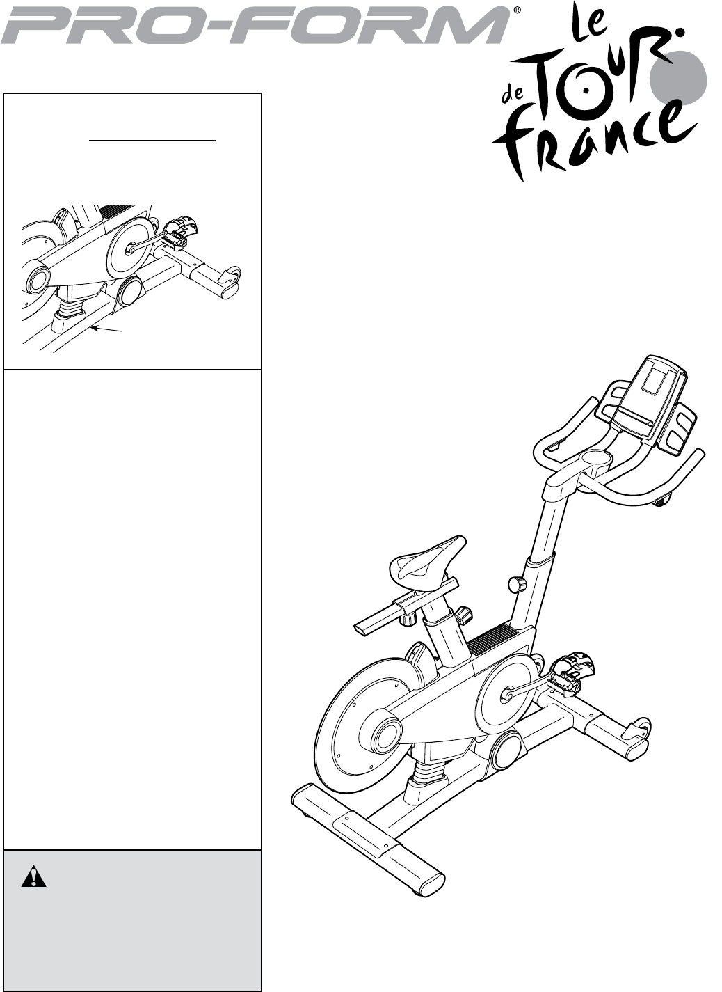
USER’S MANUAL
Serial Number
Decal
CAUTION
Read all precautions and instruc-
tions in this manual before using
this equipment. Keep this manual
for future reference.
Model No. PFEVEX79911.0
Serial No.
Write the serial number in the space
above for reference.
www.iconeurope.com
QUESTIONS?
If you have questions, or if there are
missing parts, please contact us:
UNITED KINGDOM
Call: 08457 089 009
From Ireland: 053 92 36102
Website: www.iconsupport.eu
E-mail: csuk@iconeurope.com
Write:
ICON Health & Fitness, Ltd.
c/o HI Group PLC
Express Way
CASTLEFORD
WF10 5QJ
UNITED KINGDOM
AUSTRALIA
Call: 1800 993 770
E-mail: australiacc@iconfitness.com
Write:
ICON Health & Fitness
PO Box 635
WINSTON HILLS NSW 2153
AUSTRALIA

2
PROFORM is a registered trademark of ICON IP, Inc.
LE TOUR DE FRANCE is a registered trademark of Societe du Tour de France.
This drawing shows the location(s) of the
warning decal(s). If a decal is missing or
illegible, see the front cover of this manual
and request a free replacement decal.
Apply the decal in the location shown.
Note: The decal(s) may not be shown at
actual size.
WARNING DECAL PLACEMENT . . . . . . . . . . . . . . . . . . . . . . . . . . . . . . . . . . . . . . . . . . . . . . . . . . . . . . . . . . . . . . .2
IMPORTANT PRECAUTIONS ..................................................................3
BEFORE YOU BEGIN. . . . . . . . . . . . . . . . . . . . . . . . . . . . . . . . . . . . . . . . . . . . . . . . . . . . . . . . . . . . . . . . . . . . . . . .4
PART IDENTIFICATION CHART. . . . . . . . . . . . . . . . . . . . . . . . . . . . . . . . . . . . . . . . . . . . . . . . . . . . . . . . . . . . . . . .5
ASSEMBLY . . . . . . . . . . . . . . . . . . . . . . . . . . . . . . . . . . . . . . . . . . . . . . . . . . . . . . . . . . . . . . . . . . . . . . . . . . . . . . . .6
HOW TO USE THE EXERCISE BIKE. . . . . . . . . . . . . . . . . . . . . . . . . . . . . . . . . . . . . . . . . . . . . . . . . . . . . . . . . . .13
MAINTENANCE AND TROUBLESHOOTING .....................................................26
EXERCISE GUIDELINES ....................................................................28
PART LIST. . . . . . . . . . . . . . . . . . . . . . . . . . . . . . . . . . . . . . . . . . . . . . . . . . . . . . . . . . . . . . . . . . . . . . . . . . . . . . . .29
EXPLODED DRAWING. . . . . . . . . . . . . . . . . . . . . . . . . . . . . . . . . . . . . . . . . . . . . . . . . . . . . . . . . . . . . . . . . . . . . .31
ORDERING REPLACEMENT PARTS. . . . . . . . . . . . . . . . . . . . . . . . . . . . . . . . . . . . . . . . . . . . . . . . . . . Back Cover
RECYCLING INFORMATION ......................................................... Back Cover
WARNING DECAL PLACEMENT
TABLE OF CONTENTS

3
IMPORTANT PRECAUTIONS
WARNING: To reduce the risk of serious injury, read all important precautions and
instructions in this manual and all warnings on your exercise bike before using your exercise bike.
ICON assumes no responsibility for personal injury or property damage sustained by or through the
use of this product.
1. Before beginning any exercise program,
consult your physician. This is especially
important for persons over age 35 or per-
sons with pre-existing health problems.
2. Use the exercise bike only as described in
this manual.
3. It is the responsibility of the owner to ensure
that all users of the exercise bike are ade-
quately informed of all precautions.
4. The exercise bike is intended for home use
only. Do not use the exercise bike in a com-
mercial, rental, or institutional setting.
5. Keep the exercise bike indoors, away from
moisture and dust. Do not put the exercise
bike in a garage or covered patio, or near
water.
6. Place the exercise bike on a level surface,
with a mat beneath it to protect the floor or
carpet. Make sure that there is at least 2 ft.
(0.6 m) of clearance around the exercise bike.
7. Inspect and properly tighten all parts regu-
larly. Replace any worn parts immediately.
8. Keep children under age 12 and pets away
from the exercise bike at all times.
9. Wear appropriate clothes while exercising;
do not wear loose clothes that could become
caught on the exercise bike. Always wear
athletic shoes for foot protection.
10. The exercise bike should not be used by
persons weighing more than 350 lbs.
(159 kg).
11. Always keep your back straight while using
the exercise bike; do not arch your back.
12. Over exercising may result in serious injury
or death. If you feel faint or if you experience
pain while exercising, stop immediately and
cool down.
4
Congratulations for selecting the revolutionary
PROFORM® LE TOUR DE FRANCE® exercise bike.
The LE TOUR DE FRANCE exercise bike is unlike any
other exercise bike. With an incline system that auto-
matically simulates actual road terrain, intelligent wind
resistance, and an array of other features, the
LE TOUR DE FRANCE exercise bike is designed to let
you enjoy the outdoor cycling experience indoors.
For your benefit, read this manual carefully before
you use the exercise bike. If you have questions after
reading this manual, please see the front cover of this
manual. To help us assist you, note the product model
number and serial number before contacting us. The
model number and the location of the serial number
decal are shown on the front cover of this manual.
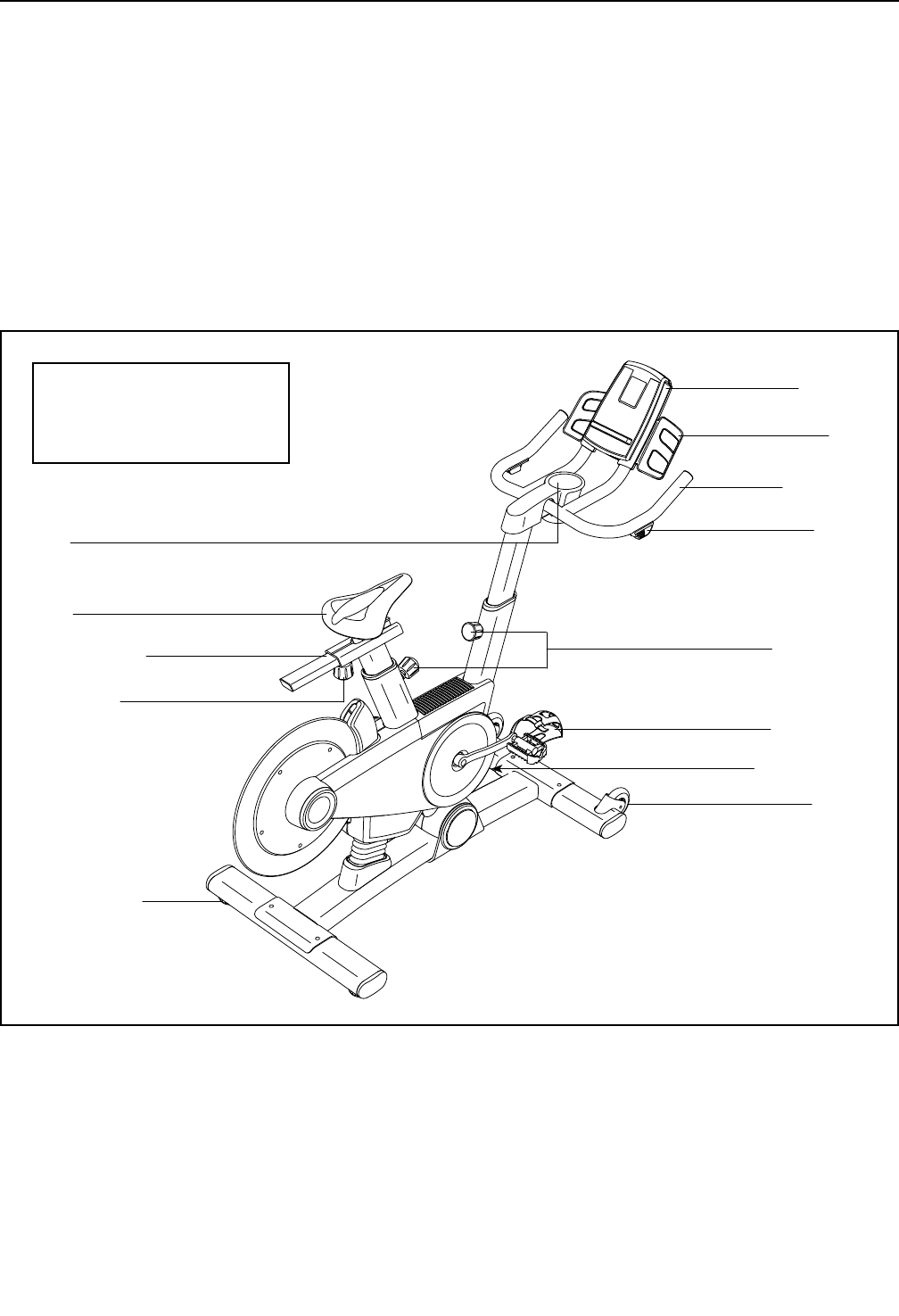
Before reading further, please familiarize yourself with
the parts that are labeled in the drawing below.
Seat
Shifter
Seat Knob
Post Knobs
Seat Carriage
Handlebar
Tray
Tray
Wheel
Pedal/Strap
Console
Leveling Foot
Power Switch
BEFORE YOU BEGIN
Length: 4 ft. 10 in. (147 cm)
Width: 2 ft. 1 in. (64 cm)
Weight: 121 lbs. (55 kg)
5
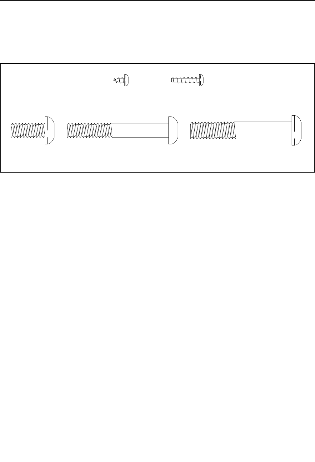
5/16" x 3/4"
Screw (91)–1
5/16" x 2 1/4"
Screw (105)–1
3/8" x 2 1/4"
Screw (74)–4
#8 x 1/4"
Screw (92)–1
#8 x 5/8"
Screw (94)–10
PART IDENTIFICATION CHART
Use the drawings below to identify the small parts needed for assembly. The number in parentheses below each
drawing is the key number of the part, from the PART LIST near the end of this manual. The number following the
key number is the quantity needed for assembly. Note: If a part is not in the hardware kit, check to see if it
has been preassembled. Extra parts may be included.
6
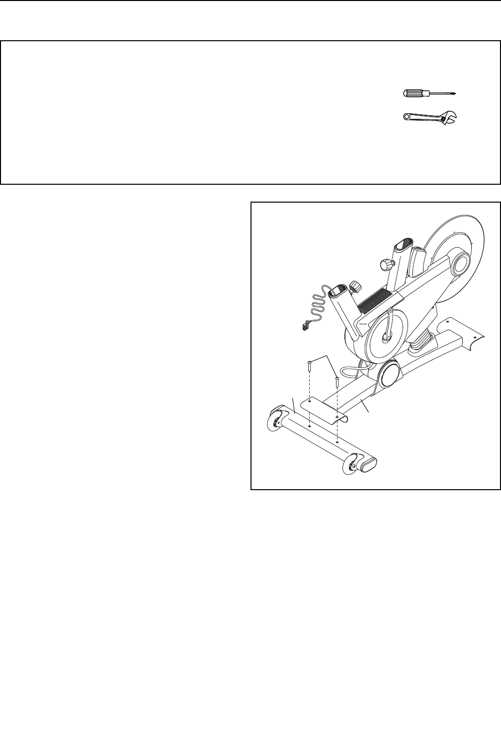
1
22
74
1
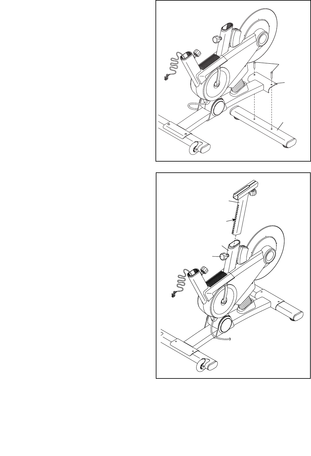
1. Orient the Front Stabilizer (22) as shown.
While a second person lifts the front of the Base
(1), attach the Front Stabilizer (22) to the Base
with two 3/8" x 2 1/4" Screws (74).
ASSEMBLY
• Assembly requires two persons.
• Place all parts in a cleared area and remove the
packing materials. Do not dispose of the packing
materials until you complete all assembly steps.
• To identify small parts, see page 5.
• In addition to the included tool(s), assembly
requires the following tools:
one Phillips screwdriver
one adjustable wrench
Assembly may be easier if you have a set of
wrenches. To avoid damaging parts, do not use
power tools.
7
2
2. While a second person lifts the rear of the Base
(1), attach the Rear Stabilizer (23) to the Base
with two 3/8" x 2 1/4" Screws (74).
74
23
1
3. Orient the Seat Post (3) as shown.
Loosen the indicated Post Knob (47) and pull it
outward. Then, insert the Seat Post (3) into the
Frame (2).
Move the Seat Post (3) upward or downward to
the desired position, release the Post Knob (47)
into an adjustment hole in the Seat Post, and
then tighten the Post Knob. Make sure that the
Post Knob is engaged in an adjustment hole.
3
2
3
47
Holes
8
4
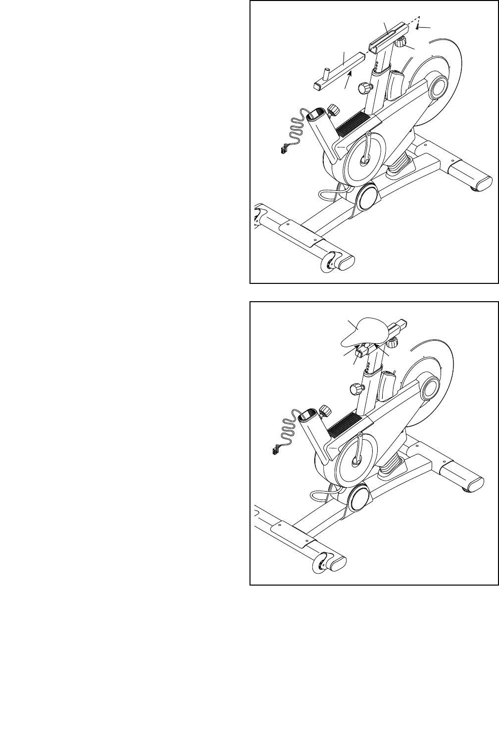
4. Orient the Seat Carriage (4) as shown.
Loosen the Seat Knob (29) and pull it downward.
Then, slide the Seat Carriage (4) into the Seat
Post (3).
Slide the Seat Carriage (4) to the desired posi-
tion, release the Seat Knob (29) into one of the
adjustment holes in the Seat Carriage, and then
tighten the Seat Knob. Make sure that the Seat
Knob is rmly engaged in an adjustment
hole.
Then, tighten a #8 x 1/4" Screw (92) into the
underside of the Seat Carriage (4).
3
4
92
Holes
29
5
5. Slide the Seat (5) onto the post on the Seat
Carriage (4). Make sure that the Seat is level
and that it is pointing straight forward. Then,
tighten the two nuts (A) beneath the Seat.
5
4
AA
9
6
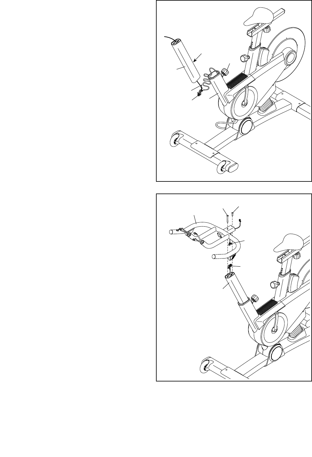
6. Orient the Handlebar Post (6) as shown.
Have a second person hold the Handlebar Post
(6) near the Frame (2). Locate the wire tie in the
Handlebar Post, and tie the lower end of the wire
tie to the Lower Wire (69). Then, pull the upper
end of the wire tie until the Lower Wire is routed
through the Handlebar Post.
Tip: Avoid pinching the Lower Wire (69).
Loosen the indicated Post Knob (47) and pull it
outward. Then, insert the Handlebar Post (6) into
the Frame (2).
Move the Handlebar Post (6) upward or down-
ward to the desired position, release the Post
Knob (47) into an adjustment hole in the
Handlebar Post, and then tighten the Post
Knob. Make sure that the Post Knob is firmly
engaged in an adjustment hole.
6
2
47
Holes
Wire Tie
69
7
7. Orient the Handlebar (7) as shown.
While a second person holds the Handlebar (7)
near the Handlebar Post (6), connect the Upper
Wire (68) to the Lower Wire (69). Then, insert
the wires into the Handlebar Post.
Tip: Avoid pinching the wires. Attach the
Handlebar (7) to the Handlebar Post (6) with
a 5/16" x 3/4" Screw (91) and a 5/16" x 2 1/4"
Screw (105). 69
68
7
105 91
6
Avoid pinching the
Lower Wire (69)
Avoid pinching
the wires
10
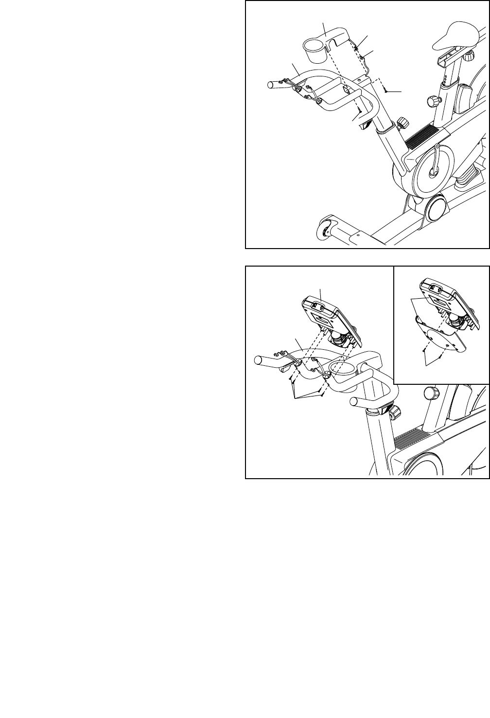
8. Orient the Handlebar Cover (67) as shown and
hold it near the Handlebar (7).
Connect the receiver wire (B) to the Extension
Wire (102). Carefully insert the excess wire into
the Handlebar (7).
Tip: Avoid pinching the wires. Insert a #8 x
5/8" Screw (94) upward into the front hole in the
Handlebar (7). Set the Handlebar Cover (67) on
the Handlebar, and tighten the Screw into the
Handlebar Cover.
Next, insert a #8 x 5/8" Screw (94) into the rear
hole in the Handlebar (7), and tighten the Screw
into the Handlebar Cover (67).
9. See the inset drawing. Remove the two indi-
cated screws (C) from the back of the Console
(9), and remove the back of the Console. Do
not discard the screws; they will be used in a
later step.
Attach the Console (9) to the Handlebar (7) with
four #8 x 5/8" Screws (94).
8
9
Avoid pinching
the wires
94
67
B
102
7
94
94
C
9
9
7
11
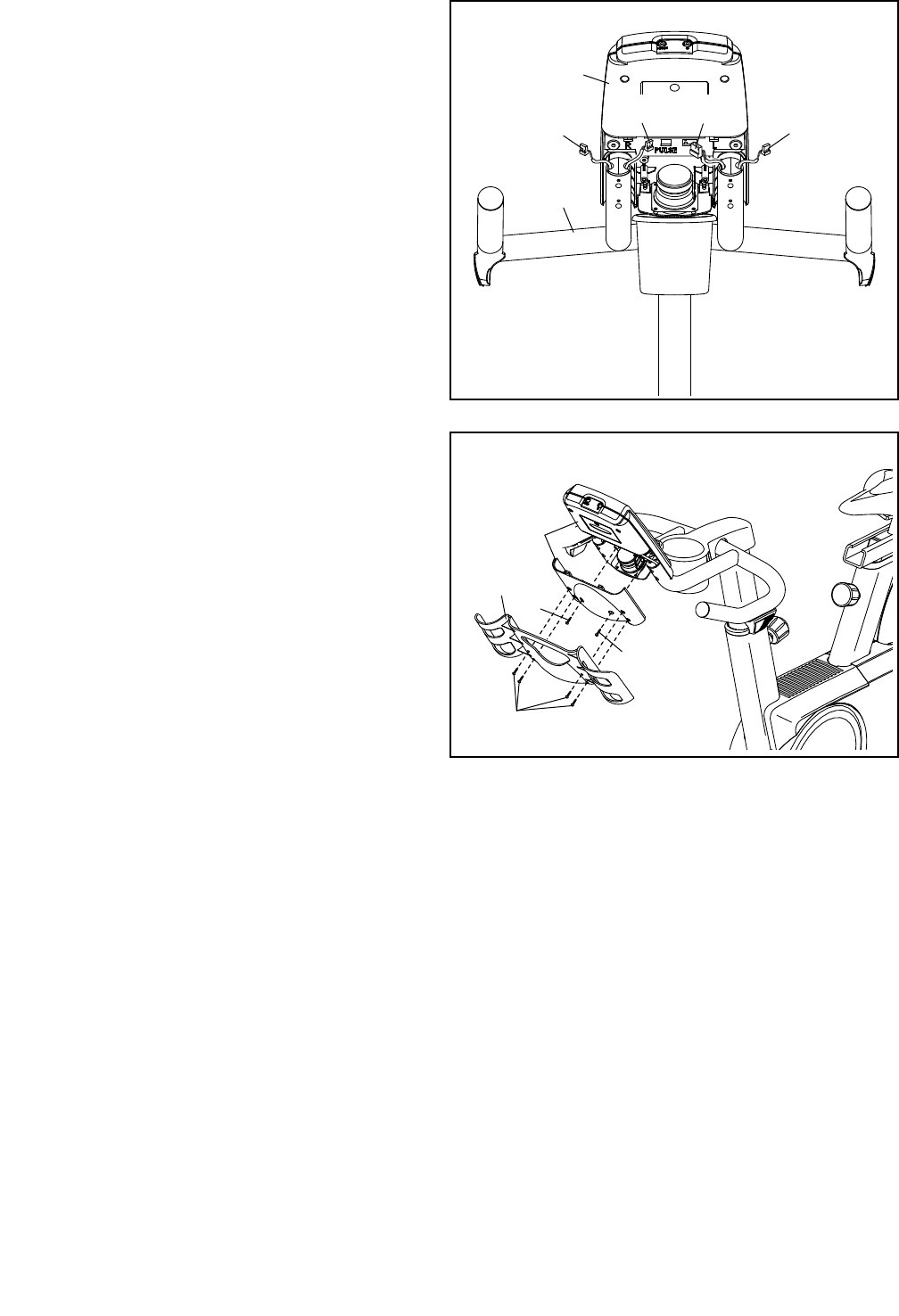
10. Plug the Left and Right Shifter Wires (70, 81) in
the Handlebar (7) into the receptacles marked
“R” and “L” on the back of the Console (9).
Next, plug the Extension Wire (102) into the
receptacle marked “Pulse.”
Plug the Upper Wire (68) into the remaining
receptacle.
9
7
10
68
81 70
102
11. Attach the back of the Console (9) to the
Console with the two screws (C) that you
removed earlier.
Next, attach the Tray (8) to the back of the
Console (9) with four #8 x 5/8" Screws (94).
11
94
C
C
9
8

12
13. Make sure that all parts are properly tightened before you use the exercise bike. Note: After assembly is
completed, some extra parts may be left over. Place a mat beneath the exercise bike to protect the floor.
12. Identify the Left Pedal (61), which is marked with
an “L.”
Using an adjustable wrench, firmly tighten the
Left Pedal (61) counterclockwise into the Left
Crank Arm (63).
Tighten the Right Pedal (not shown) clockwise
into the Right Crank Arm (not shown).
61
63
12
13
HOW TO USE THE EXERCISE BIKE
HOW TO PLUG IN THE POWER CORD
This product must be earthed. If it should malfunction
or break down, earthing provides a path of least resis-
tance for electric current to reduce the risk of electric
shock. This product’s power cord has an equipment-
earthing conductor and an earthing plug.
IMPORTANT: If the power cord is damaged, it must
be replaced with a manufacturer-recommended
power cord.
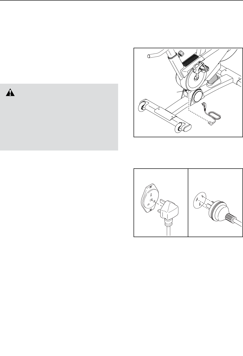
Follow the steps below to plug in the power cord.
1. Plug the power cord into the receptacle on the
exercise bike.
2. Plug the power cord into an appropriate outlet that
is properly installed and earthed in accordance with
all local codes and ordinances.
DANGER: Improper connection of
the equipment-earthing conductor can result
in an increased risk of electric shock. Check
with a qualied electrician or serviceman if
you are in doubt as to whether the product
is properly earthed. Do not modify the plug
provided with the product—if it will not t
the outlet, have a proper outlet installed by a
qualied electrician.
Receptacle
IT
FR/SP
UK
GR
RU
HU
UK
DU
GR
RU
HU
CZ
FR/
SP/
PL
IT
AUS
AUS
TYPE E
TYPE F
UK Australia
14
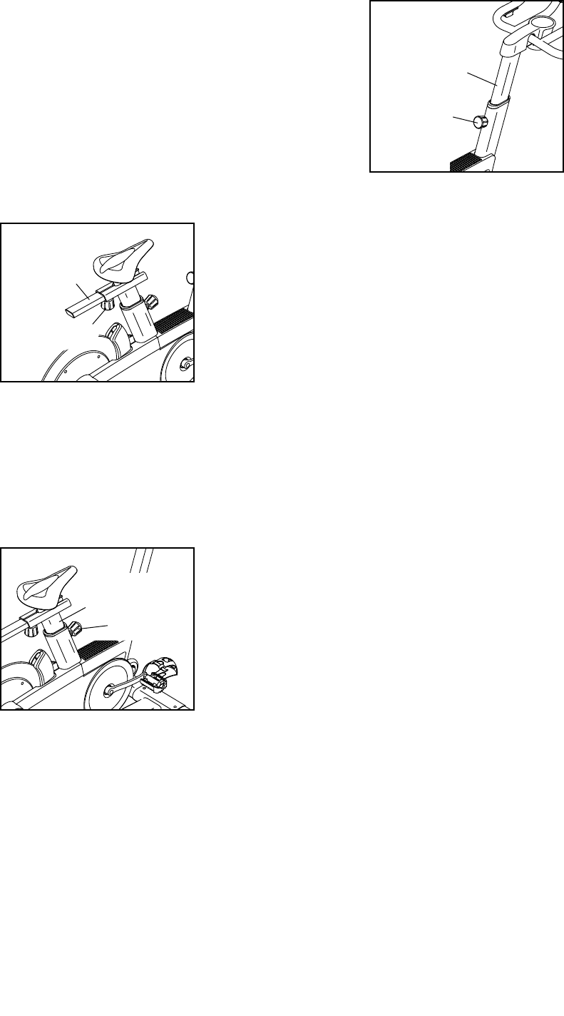
HOW TO ADJUST THE ANGLE OF THE SEAT
You can adjust the angle of the seat to the position that
is most comfortable. You can also slide the seat for-
ward or backward to increase your comfort or to adjust
the distance to the handlebar.
To adjust the seat, loosen the two nuts beneath the
seat a few turns, and then tilt the seat upward or
downward or slide the seat forward or backward to the
desired position. Then, retighten the nuts.
HOW TO ADJUST THE HORIZONTAL POSITION OF
THE SEAT
To adjust the hori-
zontal position of
the seat, rst loosen
the seat knob and
pull it downward.
Then, move the
seat carriage for-
ward or backward,
release the seat
knob, and rmly
tighten the seat
knob.
HOW TO ADJUST THE SEAT POST
For effective exercise, the seat should be at the proper
height. As you pedal, there should be a slight bend in
your knees when the pedals are in the lowest position.
To adjust the height
of the seat post,
rst loosen the
post knob and pull
it outward. Then,
move the seat post
upward or down-
ward, release the
post knob into an
adjustment hole in
the seat post, and
rmly tighten the post knob. Make sure that the post
knob is engaged in an adjustment hole.
HOW TO ADJUST THE HANDLEBAR POST
To adjust the height
of the handlebar
post, first loosen the
post knob and pull
it outward. Then,
move the handle-
bar post upward or
downward, release
the post knob into
an adjustment hole
in the handlebar
post, and firmly
tighten the post knob. Make sure that the post knob
is engaged in an adjustment hole.
HOW TO USE THE PEDALS
To use the pedals (see the drawing on page 4),
insert your shoes into the toe cages, and pull the ends
of the toe straps. To adjust the toe straps, press and
hold the tabs on the buckles, adjust the toe straps to
the desired position, and then release the tabs.
HOW TO LEVEL THE EXERCISE BIKE
If the exercise bike rocks slightly on your floor during
use, turn one or both of the leveling feet on the rear
stabilizer (see the drawing on page 4) until the
rocking motion is eliminated.
Seat
Carriage
Handlebar
Post
Post Knob
Post Knob
Seat
Post
Seat Knob
15
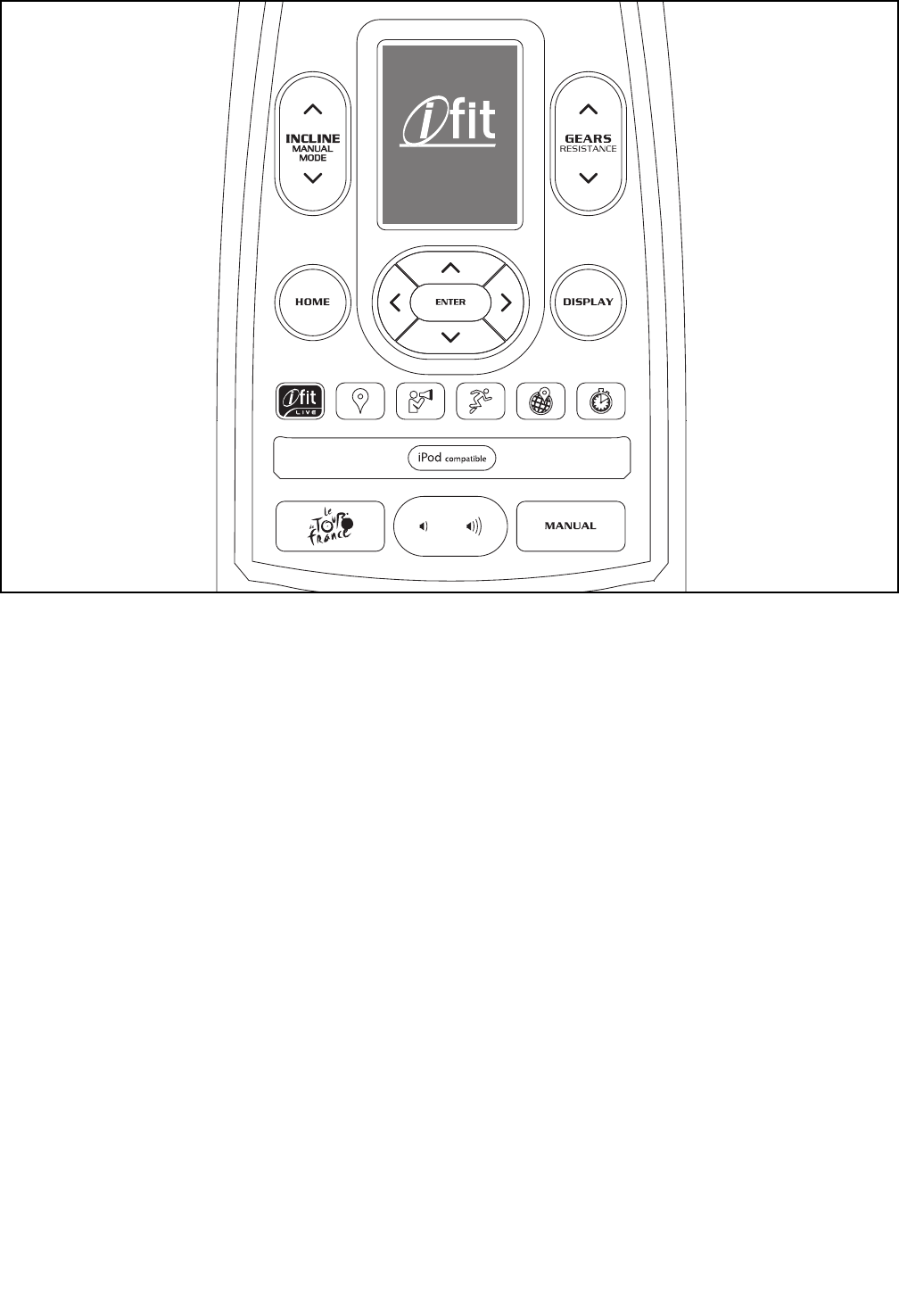
FEATURES OF THE CONSOLE
The advanced console offers an array of features
designed to make your workouts more effective and
enjoyable.
The console features new iFit Live technology that
enables the console to communicate with your wireless
network. With iFit Live technology, you can download
personalized workouts, create your own workouts,
track your workout results, and access many other
features. See www.iFit.com for complete
information.
In addition, the console offers twenty-four onboard
workouts. Each workout automatically changes the
incline (resistance) of the exercise bike to match a
preset profile or a map of real terrain and allows you to
change gears to maintain your pedaling cadence.
The console also offers a watts workout that changes
the resistance of the pedals to keep your watts output
near a target level.
When you use the manual mode of the console, you
can change the incline (resistance) of the exercise bike
and change gears with the touch of a button.
While you exercise, the console will display continuous
exercise feedback. You can also measure your heart
rate using an optional heart rate monitor.
You can even connect your MP3 player or CD player
to the console sound system and listen to your favorite
music or audio books while you exercise.
To turn on the power, see page 16. To navigate
the console menus, see page 16. To set up the
console, see page 17. To use the manual mode,
see page 17. To use an onboard workout, see
page 19. To use the watts workout, see page
20. To use an iFit Live workout, see page 21.
To use the settings mode, see page 22. To use
the maintenance mode, see page 24. To use the
sound system, see page 25.
The console can display speed and distance in either
miles or kilometers. To nd which unit of measurement
is selected, see step 5 on page 23.
Note: If there is a sheet of plastic on the display,
remove the plastic.
Chippewa
EBPF01311
PFEX01311.2
CONSOLE DIAGRAM

16
HOW TO TURN ON THE POWER
IMPORTANT: If the exercise bike has been exposed
to cold temperatures, allow it to warm to room
temperature before turning on the power. If you do
not do this, you may damage the console displays
or other electrical components.
Plug in the power cord (see
HOW TO PLUG IN THE
POWER CORD on page
13). Next, locate the
power switch on the frame
near the power cord. Press
the power switch to the
reset position.
The display will then turn on and the console will be
ready for use.
Note: When you turn on the power for the first time,
the incline system may calibrate automatically. The
exercise bike will move upward and downward as it
calibrates. When the exercise bike stops moving, the
incline system is calibrated.
IMPORTANT: If the incline system does not cali-
brate automatically, see step 7 on page 24 and
manually calibrate the incline system.
IMPORTANT: The console features a display demo
mode, designed to be used if the exercise bike is
displayed in a store. If the demo mode is turned on,
the console will not turn off and the display will not
be reset when you nish exercising. To turn off the
demo mode, see step 6 on page 23.
HOW TO NAVIGATE THE CONSOLE MENUS
You can use the Home, left, right, up, down, and Enter
buttons on the console to navigate through menus in
the display, change settings, and view console
information.
Press the Home button to return to the main menu, to
end a workout, or to return to a previous menu.
Press the up and down buttons to highlight a menu
option. Press the left button to return to a previous
menu. Press the right button to select a highlighted
menu item.
Press the Enter button to select a menu option or to
confirm a setting.
Reset
Position

17
HOW TO SET UP THE CONSOLE
Before using the exercise bike for the first time, set up
the console.
1. Connect to a wireless network.
See steps 1 and 2 on page 22 to connect to a
wireless network. Then, press the Home button to
return to the settings mode.
2. Calibrate the incline system.
First, select the maintenance mode (see steps 1
and 2 on page 24). Then, see step 7 on page
24 and calibrate the incline system of the exer-
cise bike.
3. Check for firmware updates.
If necessary, select the maintenance mode (see
steps 1 and 2 on page 24). Then, see step 3 on
page 24 and check for firmware updates.
4. Create an iFit Live account.
To create an iFit Live account, or for more infor-
mation about the account, go to www.iFit.com.
5. Begin working out.
See HOW TO USE AN IFIT LIVE WORKOUT on
page 21.
HOW TO USE THE MANUAL MODE
1. Begin pedaling or press any button on the
console to turn on the console.
See HOW TO TURN ON THE POWER on
page 16.
2. Select the main menu.
Each time you turn on the power, the main menu
will be selected automatically.
If you have selected a workout or the iFit Live
mode, press the Home button to return to the main
menu.
3. Select the manual mode.
Press the Manual button on the console to select
the manual mode.
From the main menu in the display, you can also
select iFit Live, and then select Manual Workout.
4. Change the incline (resistance) of the exercise
bike as desired.
As you pedal, change the incline (resistance) of the
exercise bike by pressing the Incline increase and
decrease buttons.
Note: After you press a button, it will take a
moment for the exercise bike to reach the selected
incline level.
CAUTION: The exercise bike can move to a
broad range of incline levels. Hold the handle-
bars and be prepared for the exercise bike to
move when you change the incline.
5. Change gears as desired.
To maintain a steady pedaling cadence, change
gears by pressing the Gears increase and
decrease buttons on the console or by pressing the
buttons on the shifters.
Note: After you press a button, it will take a
moment for the exercise bike to change to the
selected gear.

18
6. Follow your progress with the display.
The display can show the following workout
information. Press the Display button or the left,
right, up, and down buttons to view the desired
workout information.
Calories (Cals)—This display mode will show the
approximate number of calories you have burned.
Distance—This display mode will show the dis-
tance that you have pedaled in miles or kilometers.
To change the unit of measurement, see step 5 on
page 23.
Gear—This display mode will show the numbers of
the currently selected front and rear gears.
Incline—This display mode will show the incline
level of the exercise bike.
Map—When an onboard workout is selected, this
display mode will show a map of the trail and a
marker indicating your progress.
Profile—When an onboard workout is selected,
this display mode will show a profile of the incline
(elevation) settings for the workout.
Pulse—This display mode will show your heart rate
when you use an optional heart rate monitor (see
page 25).
RPM—This display mode will show your pedaling
cadence in revolutions per minute (rpm).
Speed (Spd)—This display mode will show your
pedaling cadence in miles per hour or kilometers
per hour. To change the unit of measurement, see
step 5 on page 23.
Time—This display mode will show the elapsed
time.
Watts—This display will show your approximate
power output in watts.
The wireless symbol at the
top of the display will show
the connection status of the
console. If the symbol is green,
the console is connected to
your wireless network and you have logged in to
iFit.com. If the symbol is orange, the console is
connected to your wireless network. If the symbol
is grey, the console is not connected to your wire-
less network.
Change the volume level of
the console by pressing the
volume increase and decrease
buttons.
To pause the manual mode or a workout, stop ped-
aling. The time will pause in the display. To resume
the manual mode or the workout, simply resume
pedaling.
To exit the manual mode or a workout, press the
Home button, select End Workout, and press the
Enter button.
7. Wear a heart rate monitor and measure your
heart rate if desired.
You can wear an optional heart rate monitor to
measure your heart rate. For more information
about the optional heart rate monitor, see
page 25.
When your heart beat is detected, your heart rate
will be shown in the pulse display.
8. When you are nished exercising, unplug the
power cord.
If the pedals do not move for several seconds, the
console will pause.
If the pedals do not move for several minutes and
the buttons are not pressed, the console will turn
off and the display will be reset.
When you are nished exercising, press the power
switch to the off position and unplug the power
cord. IMPORTANT: If you do not do this, the
electrical components on the exercise bike may
wear prematurely.

19
HOW TO USE AN ONBOARD WORKOUT
1. Begin pedaling or press any button on the
console to turn on the console.
See HOW TO TURN ON THE POWER on
page 16.
2. Select the main menu.
See step 2 of HOW TO USE THE MANUAL MODE
on page 17.
3. Select an onboard workout.
From the main menu in the display, select Tour De
France. You can also press the Le Tour De France
button on the console.
Then, select the desired workout. The display will
show the name, the estimated duration, and the
estimated distance of the workout. The display will
also show the approximate number of calories you
will burn during the workout.
4. Start the workout.
Begin pedaling or press the Enter button to start
the workout.
Each workout is divided into several segments.
One incline level (resistance) is programmed for
each segment. Note: The same incline level may
be programmed for consecutive segments.
During the workout, the profile will show your prog-
ress. Press the Display button repeatedly to view
the profile. The colored line at the top of the profile
will indicate the current segment of the workout.
The colored profile represents the incline level of
the current segment.
The display will also show a map of the trail and a
marker indicating your progress. Press the Display
button repeatedly to view the map.
At the end of the first segment of the workout, the
incline will automatically adjust to the incline level
for the next segment.
When the incline changes, the resistance of the
pedals will also change. To maintain a steady
pedaling cadence, change gears by pressing the
Gears increase and decrease buttons.
Note: The calorie goal is an estimate of the
number of calories that you will burn during the
workout. The actual number of calories that you
burn will depend on various factors such as
your weight. In addition, your pedaling cadence
will affect the number of calories you burn.
The workout will continue in this way until the
last segment ends. A workout summary will then
appear in the display. After you view the workout
summary, press the Enter button.
5. Follow your progress with the display.
See step 6 on page 18.
6. Wear a heart rate monitor and measure your
heart rate if desired.
See step 7 on page 18.
7. When you are nished exercising, unplug the
power cord.
See step 8 on page 18.

20
HOW TO USE THE WATTS WORKOUT
1. Begin pedaling or press any button on the
console to turn on the console.
See HOW TO TURN ON THE POWER on
page 16.
2. Select the main menu.
See step 2 of HOW TO USE THE MANUAL MODE
on page 17.
3. Select the watts workout.
From the main menu in the display, select Watts
Workout. The watts target will appear in the display.
4. Enter a target watts setting.
To enter a target watts setting, press the up and
down buttons.
5. Start the workout.
Begin pedaling or press the Enter button to start
the workout.
The target watts setting and your actual watts
output will appear in the display. The console will
regularly compare your watts output to the target
watts setting.
As you pedal, keep your watts output near the
target watts setting by adjusting your pedaling
cadence.
Note: During the watts workout, the resistance
of the pedals will adjust automatically. Do not
press the Gears buttons during the watts workout.
Pressing the Gears buttons will have no effect on
your watts output.
The target watts meter will show your watts output
relative to the target watts setting. When the arrow
is in the green zone, your watts output is close to
the target watts setting. When the arrow is in the
red zone, your watts output is not close to the tar-
get watts setting.
If your watts output is too far below or above the
target watts setting, the resistance of the pedals
will automatically increase or decrease to bring
your watts output closer to the target watts setting.
To change the target watts setting at any time
during the workout, press the up and down
buttons.
The workout will continue in this way indefinitely.
To pause the watts workout, stop pedaling. The
time will pause in the display. To resume the watts
workout, simply resume pedaling.
To exit the watts workout, press the Home button,
select End Workout, and press the Enter button.
6. Follow your progress with the display.
See step 6 on page 18.
7. Wear a heart rate monitor and measure your
heart rate if desired.
See step 7 on page 18.
8. When you are nished exercising, unplug the
power cord.
See step 8 on page 18.

21
HOW TO USE AN IFIT LIVE WORKOUT
Note: To use an iFit Live workout, you must have
access to a wireless network including an 802.11b/n
router with SSID broadcast enabled (hidden networks
are not supported). An iFit.com membership is also
required.
1. Begin pedaling or press any button on the
console to turn on the console.
See HOW TO TURN ON THE POWER on
page 16.
2. Log in to your iFit Live account.
If you have not already done so, log in to your iFit
Live account (see step 3 on page 23).
3. Select the main menu.
See step 2 of HOW TO USE THE MANUAL MODE
on page 17.
4. Select an iFit Live workout.
From the main menu in the display, select iFit
Live, and then select Today’s Workout, Map, Train,
World Tour, or Event Training to download the
next workout of that type in your schedule. Select
Compete to compete in a race that you have previ-
ously scheduled.
You can also press the iFit Live buttons on the
console. Press the Map button, the Train button,
the World Tour button, or the Event Training button
to download the next workout of that type in your
schedule. Press the Compete button to compete in
a race that you have previously scheduled.
To switch users within the iFit Live account, select
Select User and select the desired user.
From the iFit Live menu, you can also select
Manual Workout for the manual mode (see page
17) or Tour De France for an onboard workout
(see page 19).
Before some workouts will download, you must add
them to your schedule on iFit.com.
For more information about the iFit Live work-
outs, please see www.iFit.com.
When you select an iFit Live workout, the display
will show the name, duration, and distance of the
workout. The display will also show the approxi-
mate number of calories you will burn during the
workout. The display may also show a prole or
a map of the workout. If you select a competition
workout, the display may count down to the begin-
ning of the race.
5. Start the workout.
See step 4 on page 19.
During some workouts, the voice of a personal
trainer will guide you through your workout.
6. Follow your progress with the display.
See step 6 on page 18.
During a competition workout, the display will show
your progress in the race.
7. Wear a heart rate monitor and measure your
heart rate if desired.
See step 7 on page 18.
8. When you are nished exercising, unplug the
power cord.
See step 8 on page 18.
For more information about the iFit Live mode, go
to www.iFit.com.

22
HOW TO USE THE SETTINGS MODE
The console features a settings mode that allows you
to connect the console to your own wireless network
and to log in to your iFit Live account. The settings
mode also allows you to select the unit of measure-
ment, to turn on and turn off the display demo mode,
to turn on and turn off the incline lockout, and to select
a gearing option. You may also be able to select a
language.
1. Select the settings mode.
Turn on the console (see step 1 of HOW TO USE
THE MANUAL MODE on page 17 ). Next, select
the main menu (see step 2 on page 17). Then,
select Settings. The settings menu will appear in
the display.
2. Connect to a wireless network.
From the settings menu, select WiFi. Then, select
Standard Wifi Setup, Advanced Wifi Setup, or WPS
Setup.
Note: You must have your own wireless network
and an 802.11b/n router with SSID broadcast
enabled (hidden networks are not supported).
The iFit Live mode supports unsecured and
secured (WEP, WPA, and WPA2) encryption. A
broadband connection is recommended; perfor-
mance depends on connection speed.
If you select Standard Wifi Setup, a list of wire-
less networks will appear in the display. Select the
desired network.
Note: It may take a few moments for the list of
networks to appear. You will need to know your
network name (SSID) for the standard setup. If
your network has a password, you will also need to
know the password.
The keyboard will then appear in the display. Using
the left, right, up, down and Enter buttons, enter
your password (passphrase) and select Done.
Note: If your network does not have a password,
simply select Done.
If you are having problems connecting to the
selected network, make sure that your password is
correct. Note: Passwords are case-sensitive.
The display will inform you when the console has
connected to your wireless network. Press the
Enter button to close the standard setup mode.
If you select Advanced Wi Setup, a list of wire-
less networks will appear in the display. Select the
desired network. Note: It may take a few moments
for the list of networks to appear.
Note: You will need to know your network name
(SSID), your network password, your IP address,
your netmask, your gateway address, and your
global DNS server for the advanced setup.
The keyboard will then appear in the display. Using
the left, right, up, down and Enter buttons, enter
your password (passphrase) and select Done.
Repeat these actions to enter your IP address,
your netmask, your gateway address, and your
global DNS.
If you are having problems connecting to the
selected network, make sure that you have entered
case-sensitive information correctly.
The display will inform you when the console has
connected to your wireless network. Press the
Enter button to close the advanced setup mode.
If you select WPS Setup, follow the instructions
that appear in the display.
Note: If you have questions after following
these instructions, go to support.ifit.com for
assistance.

23
3. Log in to your iFit Live account.
From the settings menu, select WiFi. Then, select
iFit Live Login.
The keyboard will then appear in the display. Using
the left, right, up, down and Enter buttons, enter
your iFit Live password (passphrase) and select
Done.
Note: You can switch users within the iFit Live
account. From the iFit Live menu, select Select
User and select the desired user.
To create an iFit Live account, or for more infor-
mation about the account, go to www.iFit.com.
4. Select a language.
From the settings menu, select International. Then,
select Language. The currently selected language
will be highlighted.
Select the desired language. Note: This feature
may not be enabled.
5. Select the unit of measurement.
From the settings menu, select International. Then,
select Display Units. The currently selected unit of
measurement will be highlighted.
Select U.S. (miles) to display speed and distance in
miles or select Metric (kilometers) to display speed
and distance in kilometers.
6. Turn on or turn off the display demo mode.
The console features a display demo mode,
designed to be used if the exercise bike is dis-
played in a store. If the demo mode is turned on,
the console will not turn off and the display will not
be reset when you nish exercising.
You can turn on or turn off the display demo mode.
From the settings menu, select Demo Mode. The
currently selected demo mode option will be
highlighted.
To turn on the demo mode, select On. To turn off
the demo mode, select Off.
7. Turn on or turn off the incline lockout.
The console features an incline lockout that will
prevent the exercise bike from inclining or
declining.
You can turn on or turn off the incline lockout. From
the settings menu, select Incline Lockout. The cur-
rently selected incline lockout option will be
highlighted.
To turn on the incline lockout, select On. To turn off
the incline lockout, select Off.
Note: If you use an onboard workout when the
incline lockout is turned on, the resistance of the
pedals will change to match the programmed
incline levels for the workout.
8. Select a gearing option.
From the settings menu, select Gearing. Then,
select the desired gearing option(s) for the exercise
bike.
Note: For detailed information on gearing
options, consult a road cycling book or other
road cycling resource.
9. Exit the settings mode.
To exit the settings mode, press the Home button.

24
HOW TO USE THE MAINTENANCE MODE
The console features a maintenance mode that allows
you to update the console firmware, restore the default
settings, view technical information, perform a net-
work test, calibrate the incline, and calibrate the power
meter.
1. Select the settings mode.
See step 1 on page 22.
2. Select the maintenance mode.
From the settings menu, select Maintenance. The
maintenance menu will appear in the display.
The following information will appear as the header
of each maintenance menu option:
If the console is connected to the controller of the
exercise bike, the controller dot will be green; if it is
not, the dot will flash.
If the exercise bike is connected to your wireless
network, the network dot will be green; if it is not,
the dot will be red.
3. Update the console firmware.
For the best results, regularly check for firm-
ware updates.
From the maintenance menu, select Firmware
Update. Press the Enter button to download the
latest firmware for the console.
IMPORTANT: To avoid damaging the exercise
bike, do not turn off the power while the firm-
ware is being updated.
The display will show the progress of the update.
When the update is complete, the console will turn
off and then turn back on. If it does not, press the
power switch on the exercise bike to the off posi-
tion. Wait for several seconds, and then press the
power switch to the reset position. It may take a
few minutes for the console to be ready for use.
4. Restore the default settings.
From the maintenance menu, select Restore
Defaults. Then, press Enter to restore the console
to the original settings from the factory.
5. View technical information.
From the maintenance menu, select Technical Info.
View the total number of hours that the exercise
bike has been used, the total distance that has
been pedaled, and other information.
After you view the information, press the Enter
button.
6. Perform a network test.
From the maintenance menu, select Network Test.
The console will run a network test and check the
connection status of the console and the exercise
bike.
After you view the results of the network test, press
the Enter button.
7. Calibrate the incline system of the exercise
bike.
From the maintenance menu, select Calibrate
Incline. Then, press the Enter button to calibrate
the incline system.
The exercise bike will automatically rise to the max-
imum incline level, lower to the minimum incline
level, and then return to the starting position. This
will calibrate the incline system.
IMPORTANT: Keep pets, feet, and other objects
away from the exercise bike while the incline
system is calibrating. In an emergency, press
the Enter button to stop the incline calibration.
When the incline system is calibrated, press the
Enter button.
25
8. Calibrate the power meter on the exercise bike.
Note: This feature may not be enabled for this
exercise bike.
Calibrate the power meter on the exercise bike
only if instructed to do so by an authorized
service representative.
From the maintenance menu, select Calibrate
Watts. The keyboard will then appear in the dis-
play. Using the left, right, up, down and Enter
buttons, enter the spring constant for the power
meter.
9. Exit the maintenance mode.
To exit the maintenance mode, press the Home
button.
HOW TO USE THE SOUND SYSTEM
To play music or audio books through the console
sound system while you exercise, plug one end of your
audio cable into the jack on the console. Plug the other
end into a jack on your MP3 player or CD player; make
sure that your audio cable is fully plugged in.
Next, press the play button on your
MP3 player or CD player. Adjust
the volume level using the volume
increase and decrease buttons on
the console or the volume control
on your MP3 player or CD player.
To use headphones with the console, plug your head-
phones cable into the headphones jack on the console.
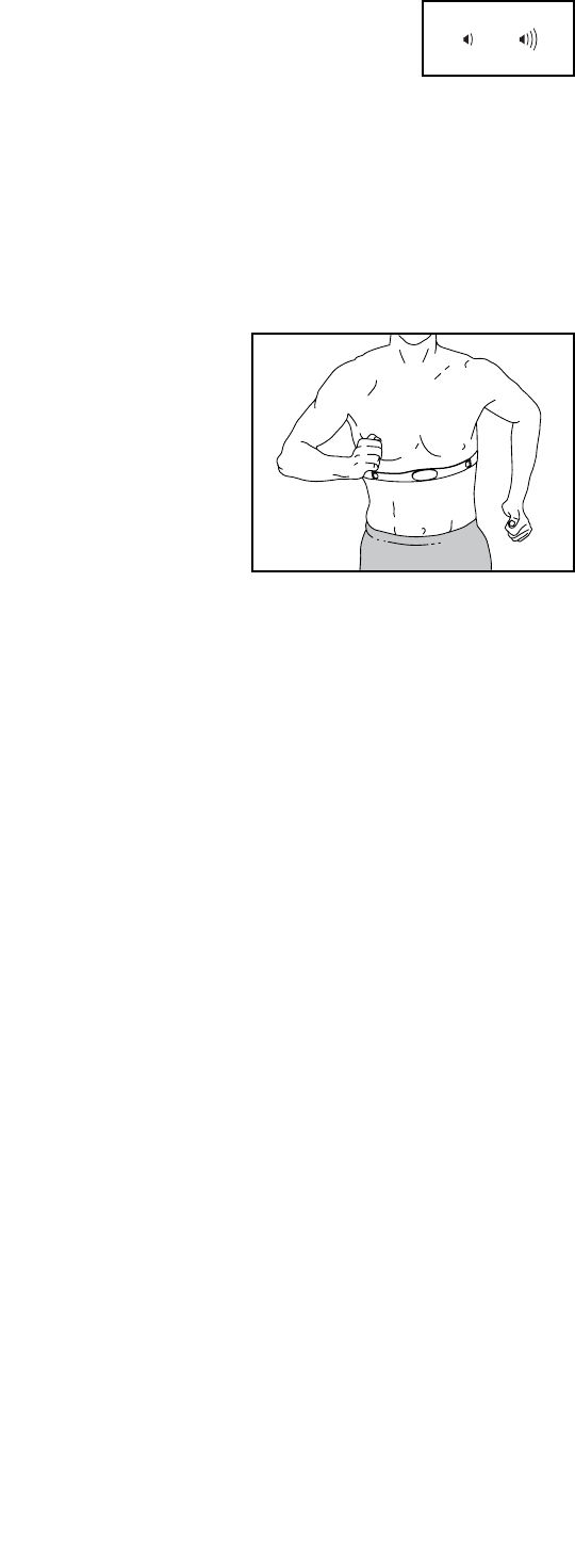
THE OPTIONAL HEART RATE MONITOR
Whether your
goal is to
burn fat or to
strengthen your
cardiovascular
system, the key
to achieving the
best results is
to maintain the
proper heart
rate during your
workouts. The optional chest heart rate monitor will
enable you to continuously monitor your heart rate
while you exercise, helping you to reach your personal
fitness goals. To purchase a chest heart rate moni-
tor, please see the front cover of this manual.
26
HOW TO MAINTAIN THE EXERCISE BIKE
Inspect and tighten all parts of the exercise bike regu-
larly. Replace any worn parts immediately.
To clean the exercise bike, use a damp cloth and a
small amount of mild detergent. IMPORTANT: To
avoid damage to the console, keep liquids away
from the console and keep the console out of
direct sunlight.
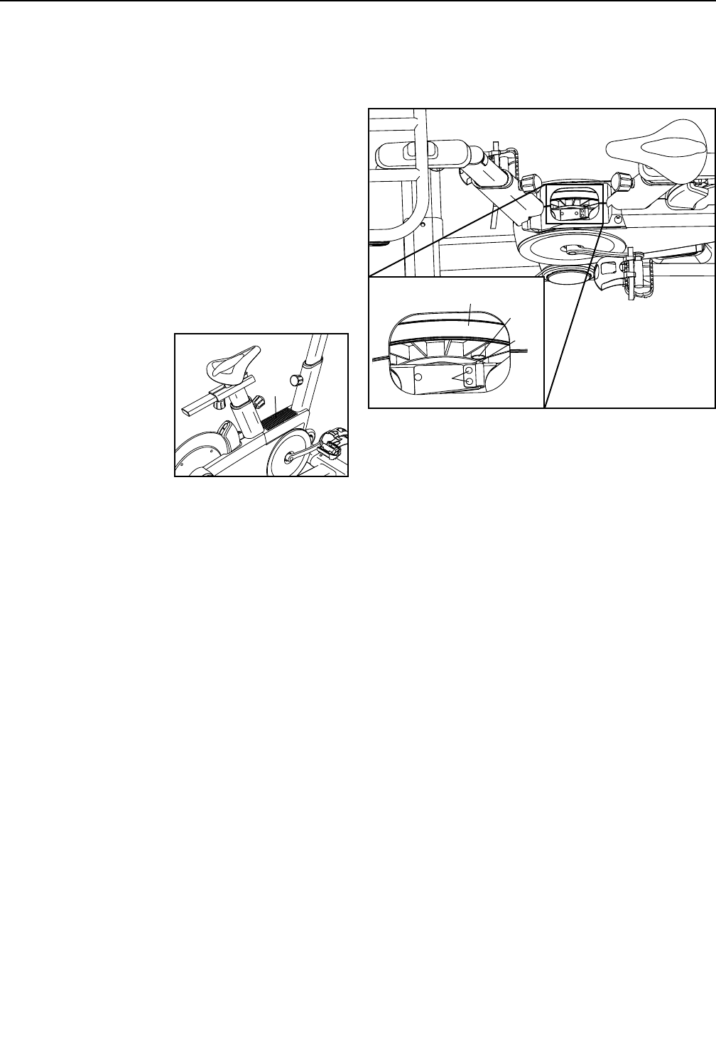
HOW TO ADJUST THE REED SWITCH
If the console does not display correct feedback, the
reed switch should be adjusted.
To adjust the reed
switch, first press
the power switch to
the off position and
unplug the power
cord. Then, use a flat
screwdriver to remove
the Upper Shield (10)
from the exercise bike.
Locate the Reed Switch (35). Loosen, but do not
remove, the two #8 x 19mm Tek Screws (97).
Next, rotate the Crank Pulley (53) until a Magnet (55)
is aligned with the Reed Switch (35). Slide the Reed
Switch slightly toward or away from the Magnet. Then,
retighten the #8 x 19mm Tek Screws (97).
Plug in the power cord and press the power switch to
the reset position. Rotate the Crank Pulley (53) for a
moment. Repeat these actions until the console dis-
plays correct feedback.
When the reed switch is correctly adjusted, reattach
the upper shield.
MAINTENANCE AND TROUBLESHOOTING
10
55
53
35
97
27
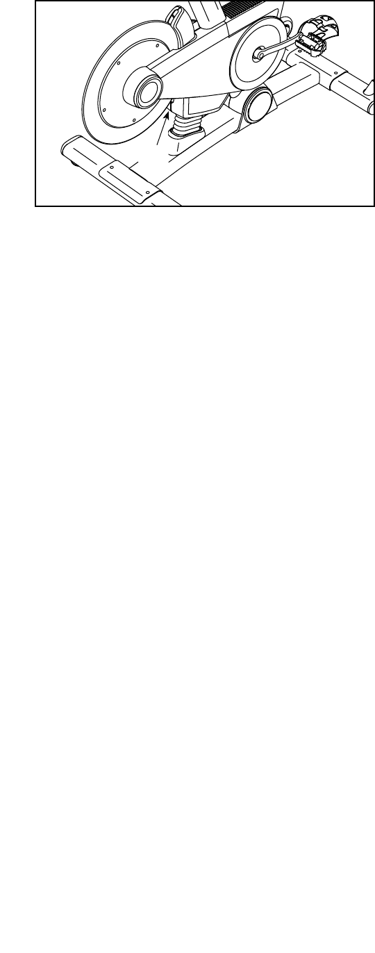
HOW TO ADJUST THE DRIVE BELT
If the pedals slip while you are pedaling, the drive belt
may need to be adjusted.
See the EXPLODED DRAWING on page 31 to iden-
tify the parts mentioned below.
To adjust the Drive Belt (66), first press the power
switch to the off position and unplug the power
cord.
Locate the access hole in the underside of the
Right Shield (12). Using a hex key, tighten the Idler
Adjustment Screw (39) until the Drive Belt (66) is tight.
39
28
These guidelines will help you to plan your exercise
program. For detailed exercise information, obtain a
reputable book or consult your physician. Remember,
proper nutrition and adequate rest are essential for
successful results.
EXERCISE INTENSITY
Whether your goal is to burn fat or to strengthen your
cardiovascular system, exercising at the proper inten-
sity is the key to achieving results. You can use your
heart rate as a guide to find the proper intensity level.
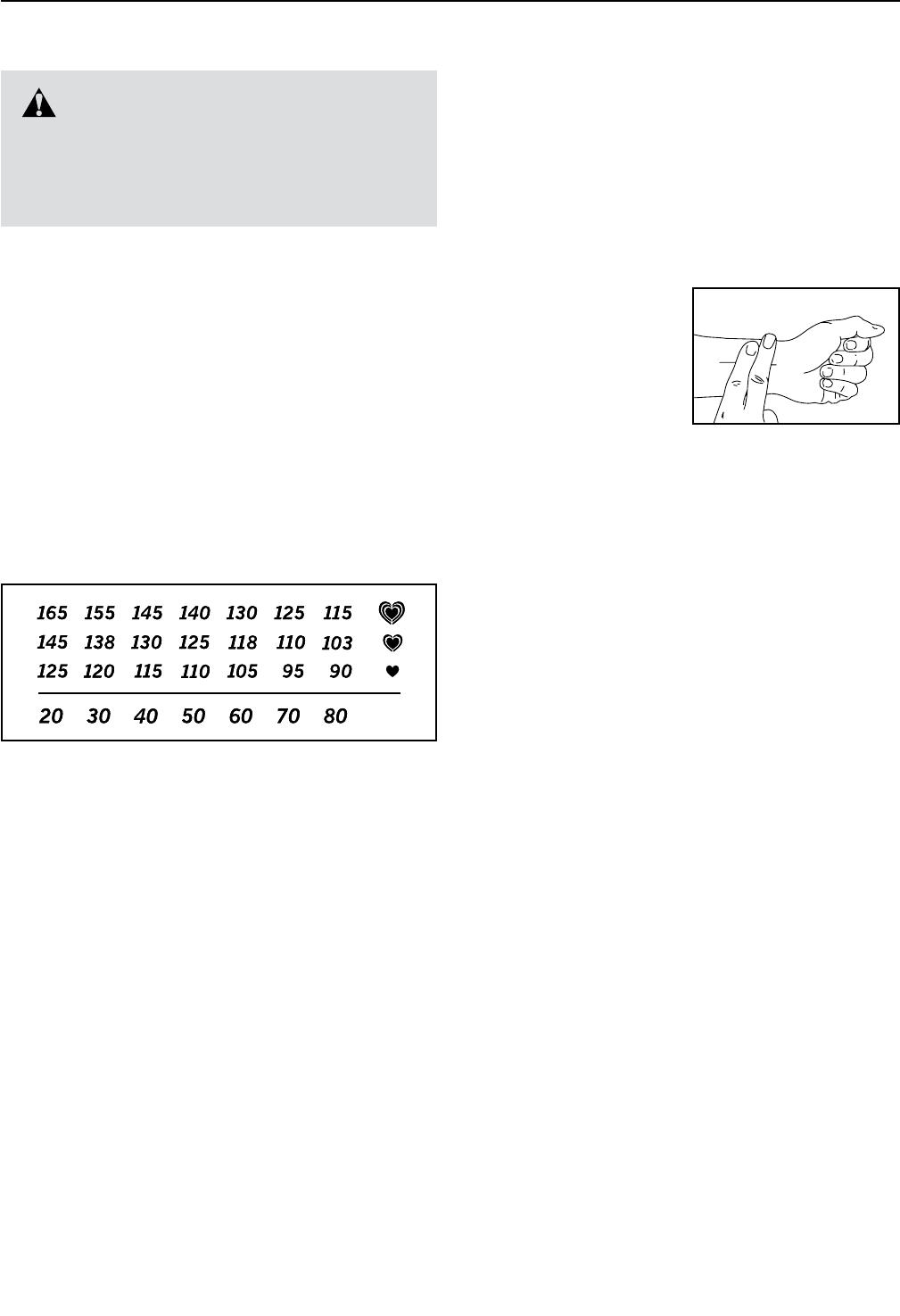
The chart below shows recommended heart rates for
fat burning and aerobic exercise.
To find the proper intensity level, find your age at the
bottom of the chart (ages are rounded off to the near-
est ten years). The three numbers listed above your
age define your “training zone.” The lowest number is
the heart rate for fat burning, the middle number is the
heart rate for maximum fat burning, and the highest
number is the heart rate for aerobic exercise.
Burning Fat—To burn fat effectively, you must exer-
cise at a low intensity level for a sustained period of
time. During the first few minutes of exercise, your
body uses carbohydrate calories for energy. Only after
the first few minutes of exercise does your body begin
to use stored fat calories for energy. If your goal is to
burn fat, adjust the intensity of your exercise until your
heart rate is near the lowest number in your training
zone. For maximum fat burning, exercise with your
heart rate near the middle number in your training
zone.
Aerobic Exercise—If your goal is to strengthen your
cardiovascular system, you must perform aerobic
exercise, which is activity that requires large amounts
of oxygen for prolonged periods of time. For aerobic
exercise, adjust the intensity of your exercise until your
heart rate is near the highest number in your training
zone.
HOW TO MEASURE YOUR HEART RATE
To measure your heart
rate, exercise for at least
four minutes. Then, stop
exercising and place
two fingers on your
wrist as shown. Take a
six-second heartbeat
count, and multiply the
result by 10 to find your heart rate. For example, if your
six-second heartbeat count is 14, your heart rate is 140
beats per minute.
WORKOUT GUIDELINES
Warming Up—Start with 5 to 10 minutes of stretch-
ing and light exercise. A warm-up increases your body
temperature, heart rate, and circulation in preparation
for exercise.
Training Zone Exercise—Exercise for 20 to 30 min-
utes with your heart rate in your training zone. (During
the first few weeks of your exercise program, do not
keep your heart rate in your training zone for longer
than 20 minutes.) Breathe regularly and deeply as you
exercise —never hold your breath.
Cooling Down—Finish with 5 to 10 minutes of stretch-
ing. Stretching increases the flexibility of your muscles
and helps to prevent post-exercise problems.
EXERCISE FREQUENCY
To maintain or improve your condition, complete three
workouts each week, with at least one day of rest
between workouts. After a few months of regular exer-
cise, you may complete up to five workouts each week,
if desired. Remember, the key to success is to make
exercise a regular and enjoyable part of your everyday
life.
WARNING: Before beginning this
or any exercise program, consult your physi-
cian. This is especially important for persons
over age 35 or persons with pre-existing
health problems.
EXERCISE GUIDELINES

29
Key No. Qty. Description Key No. Qty. Description
1 1 Base
2 1 Frame
3 1 Seat Post
4 1 Seat Carriage
5 1 Seat
6 1 Handlebar Post
7 1 Handlebar
8 1 Tray
9 1 Console
10 1 Upper Shield
11 1 Left Shield
12 1 Right Shield
13 2 Shield Cover
14 1 Right Magnet Cover
15 1 Left Magnet Cover
16 1 Left Frame Cover
17 1 Right Frame Cover
18 1 Base Shield
19 1 Flex Cover
20 2 Cover Mount
21 2 Base Cover
22 1 Front Stabilizer
23 1 Rear Stabilizer
24 4 Stabilizer Cap
25 2 Leveling Foot
26 2 Foot
27 2 Wheel
28 2 Seat Carriage Cap
29 1 Seat Knob
30 1 Lift Motor
31 1 Resistance Motor
32 1 Resistance Magnet
33 1 Arm
34 1 Magnet Axle
35 1 Reed Switch/Wire
36 1 Clamp
37 1 Idler Pulley
38 1 Idler Bolt
39 1 Idler Adjustment Screw
40 1 Flywheel Ring
41 1 Flywheel Hub
42 1 Flywheel Axle
43 1 Flywheel Spacer
44 1 Thrust Washer
45 1 Flywheel Pulley
46 2 Post Bushing
47 2 Post Knob
48 1 Power Switch
49 1 Grommet
50 1 Control Board
51 1 Board Bracket
52 4 Standoff
53 1 Crank Pulley
54 1 Crank
55 2 Magnet
56 1 Crank Spacer
57 2 Bearing
58 1 Snap Ring
59 2 Frame Bushing
60 1 Pivot Axle
61 1 Left Pedal
62 1 Right Pedal
63 1 Left Crank Arm
64 1 Right Crank Arm
65 2 Crank Arm Cap
66 1 Drive Belt
67 1 Handlebar Cover
68 1 Upper Wire
69 1 Lower Wire
70 1 Left Shifter/Wire
71 3 3/8" Jam Nut
72 2 1/2" Washer
73 2 1/2" x 1" Screw
74 4 3/8" x 2 1/4" Screw
75 2 5/16" x 1 3/4" Bolt
76 2 5/16" Locknut
77 1 M10 x 35mm Hex Screw
78 2 5/16" x 17mm Flange Screw
79 4 M6 x 20mm Screw
80 4 M6 Nut
81 1 Right Shifter/Wire
82 5 #10 x 1/2" Flat Head Screw
83 1 1/4" x 125mm Flat Head Screw
84 4 Wheel Spacer
85 2 M10 Washer
86 2 M8 x 15mm Screw
87 2 Lift Motor Bushing
88 8 #8 x 13mm Screw
89 4 #8 x 16mm Screw
90 2 Mount/Screw
PART LIST Model No. PFEVEX79911.0 R0312A

30
Key No. Qty. Description Key No. Qty. Description
91 1 5/16” x 3/4” Screw
92 1 #8 x 1/4" Screw
93 2 #8 Star Washer
94 9 #8 x 5/8" Screw
95 10 #8 x 1/2" Screw
96 4 M4 x 12mm Flange Screw
97 2 #8 x 19mm Tek Screw
98 1 Electronics Shield
99 4 1/4" Flange Nut
100 1 M10 Locknut
101 1 Receiver/Wire
102 1 Extension Wire
103 4 1/4" Split Washer
104 4 M3.5 x 13mm Screw
105 1 5/16" x 2 1/4" Screw
106 4 Wire Guide
* – Assembly Tool
* – User’s Manual
* – Power Cord
* – Lift Motor Wire
* – Resistance Motor Wire
* – Blue Wire
* – Green Wire
* – White Wire
Note: Specifications are subject to change without notice. For information about ordering replacement parts, see
the back cover of this manual. *These parts are not illustrated.
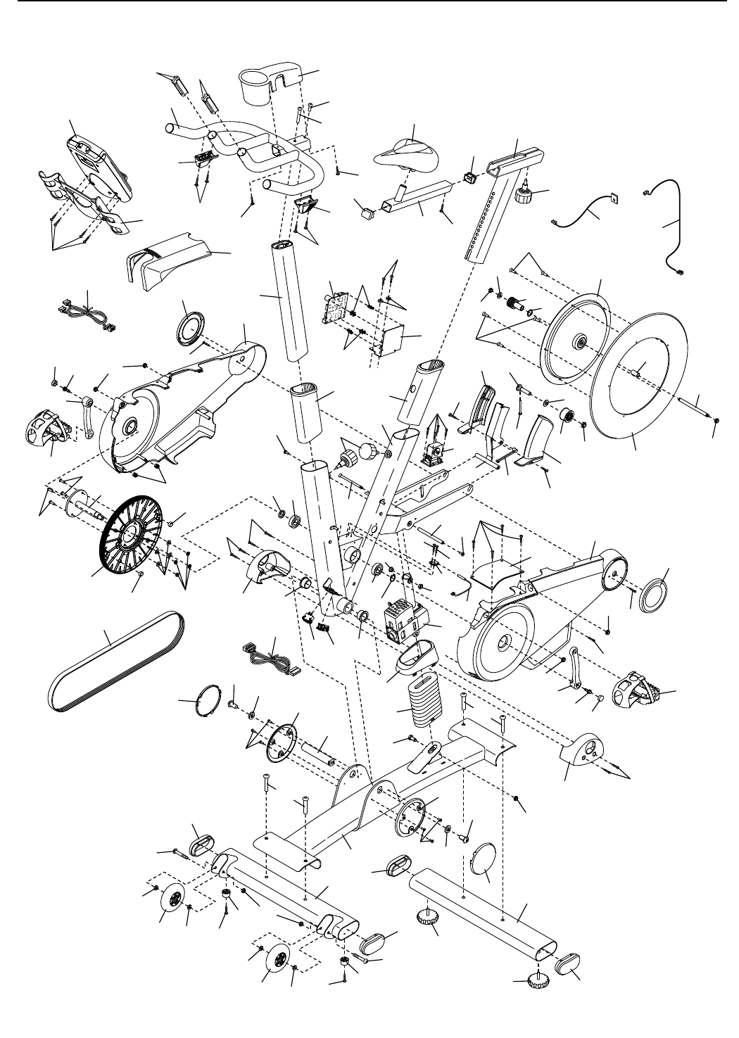
31
EXPLODED DRAWING
1
2
6
8
9
10
11
12
13
13
14
15
17
16
18
19
20
20
21
21 23
24
24
25
25
27
47
30
31
32 33
3486
87
35
36
87
97
97
96 95
95
39
85
37 71
38
40
41
42
43
71
44
45
82
85
71
82
46
46
48 49
86
83
53
54 56
55
55
57
57
58
59
59
60
62
61
64
65 78
63
65
78
95
94
77
73
88
66
88
73
94
88
88
80
103
79
79
95
94
90
74
74
68
69
72
72
27
84
84
84
84
22
24
24
26
26
75
89
89
76
75
99
99
99
98
95
100
101 102
51
50
52
52
89
93
3
4
5
28
28 29
92
7
104
104
81
70
94
94
105
67
91
106 106
Model No. PFEVEX79911.0 R0312A
Part No. 322478 R0312A Printed in China © 2012 ICON IP, Inc.
To order replacement parts, please see the front cover of this manual. To help us assist you, be prepared to
provide the following information when contacting us:
• the model number and serial number of the product (see the front cover of this manual)
• the name of the product (see the front cover of this manual)
• the key number and description of the replacement part(s) (see the PART LIST and the EXPLODED
DRAWING near the end of this manual)
ORDERING REPLACEMENT PARTS
This electronic product must not be disposed of in municipal waste. To pre-
serve the environment, this product must be recycled after its useful life as
required by law.
Please use recycling facilities that are authorized to collect this type of waste in
your area. In doing so, you will help to conserve natural resources and improve
European standards of environmental protection. If you require more information
about safe and correct disposal methods, please contact your local city office or the
establishment where you purchased this product.
RECYCLING INFORMATION
