Proform Pfrw3914C0 440R Rower Users Manual
2015-04-14
: Proform Proform-Pfrw3914C0-440R-Rower-Users-Manual-701338 proform-pfrw3914c0-440r-rower-users-manual-701338 proform pdf
Open the PDF directly: View PDF ![]() .
.
Page Count: 24
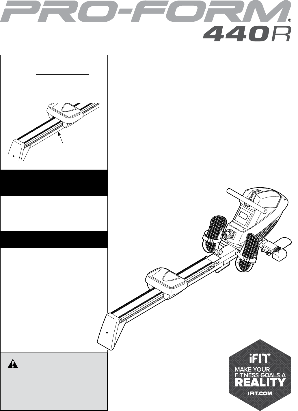
Serial Number
Decal (under rail)
USER’S MANUAL
Model No. PFRW3914C.0
Serial No.
Write the serial number in the space
above for reference.
www.proformfitness.ca
CAUTION
Read all precautions and instruc-
tions in this manual before using
this equipment. Keep this manual
for future reference.
To register your product and
activate your warranty today,
go to www.iconservice.ca.
Call toll-free 1-888-936-4266
Mon.–Fri. 7:30 a.m.–4:30 p.m. ET
(excluding holidays)
or email us at
customerservice@iconcanada.ca
Please do not contact the store.
ACTIVATE YOUR
WARRANTY
CUSTOMER SERVICE
2
PROFORM is a registered trademark of ICON Health & Fitness, Inc.
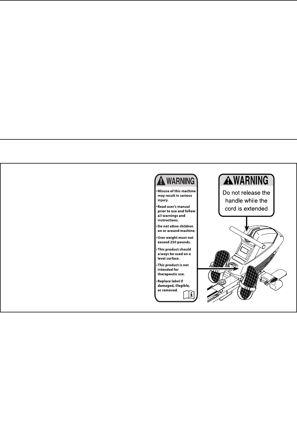
WARNING DECAL PLACEMENT
TABLE OF CONTENTS
This drawing shows the location(s) of the warning
decal(s). If a decal is missing or illegible, see
the front cover of this manual and request a
free replacement decal. Apply the decal in the
location shown. Note: The decal(s) may not be
shown at actual size.
WARNING DECAL PLACEMENT . . . . . . . . . . . . . . . . . . . . . . . . . . . . . . . . . . . . . . . . . . . . . . . . . . . . . . . . . . . . . . .2
IMPORTANT PRECAUTIONS ..................................................................3
BEFORE YOU BEGIN. . . . . . . . . . . . . . . . . . . . . . . . . . . . . . . . . . . . . . . . . . . . . . . . . . . . . . . . . . . . . . . . . . . . . . . .5
PART IDENTIFICATION CHART. . . . . . . . . . . . . . . . . . . . . . . . . . . . . . . . . . . . . . . . . . . . . . . . . . . . . . . . . . . . . . . .6
ASSEMBLY . . . . . . . . . . . . . . . . . . . . . . . . . . . . . . . . . . . . . . . . . . . . . . . . . . . . . . . . . . . . . . . . . . . . . . . . . . . . . . . .7
HOW TO USE THE ROWER. . . . . . . . . . . . . . . . . . . . . . . . . . . . . . . . . . . . . . . . . . . . . . . . . . . . . . . . . . . . . . . . . .14
MAINTENANCE AND TROUBLESHOOTING ....................................................17
EXERCISE GUIDELINES ....................................................................18
PART LIST. . . . . . . . . . . . . . . . . . . . . . . . . . . . . . . . . . . . . . . . . . . . . . . . . . . . . . . . . . . . . . . . . . . . . . . . . . . . . . . .21
EXPLODED DRAWING. . . . . . . . . . . . . . . . . . . . . . . . . . . . . . . . . . . . . . . . . . . . . . . . . . . . . . . . . . . . . . . . . . . . . .23
ORDERING REPLACEMENT PARTS .................................................. Back Cover
LIMITED WARRANTY. . . . . . . . . . . . . . . . . . . . . . . . . . . . . . . . . . . . . . . . . . . . . . . . . . . . . . . . . . . . . . . Back Cover

3
IMPORTANT PRECAUTIONS
WARNING: To reduce the risk of serious injury, read all important precautions and
instructions in this manual and all warnings on your rower before using your rower. ICON assumes
no responsibility for personal injury or property damage sustained by or through the use of this
product.
1. It is the responsibility of the owner to ensure
that all users of the rower are adequately
informed of all precautions.
2. Before beginning any exercise program,
consult your physician. This is especially
important for persons over age 35 or per-
sons with pre-existing health problems.
3. Use the rower only as described in this
manual.
4. The rower is intended for home use only. Do
not use the rower in a commercial, rental, or
institutional setting.
5. Keep the rower indoors, away from moisture
and dust. Do not put the rower in a garage or
covered patio, or near water.
6. Place the rower on a level surface, with a mat
beneath it to protect the floor or carpet. Make
sure that there is at least 2 ft. (0.6 m) of clear-
ance around the rower.
7. Inspect and properly tighten all parts regu-
larly. Replace any worn parts immediately.
8. Keep children under age 12 and pets away
from the rower at all times.
9. Wear appropriate clothes while exercising;
do not wear loose clothes that could become
caught on the rower. Always wear athletic
shoes for foot protection.
10. The rower should not be used by persons
weighing more than 250 lbs. (113 kg).
11. Always keep your back straight while using
the rower; do not arch your back.
12. Do not release the row bar while the cord is
extended.
13. Over exercising may result in serious injury
or death. If you feel faint, if you become short
of breath, or if you experience pain while
exercising, stop immediately and cool down.
14. This Class [B] digital apparatus complies
with Canadian ICES-003.
15. Dispose of batteries in accordance with all
local codes and ordinances.
SERVICE
4
Your new tness equipment represents a signicant investment
in your health. Protect your investment now from unexpected
mechanical or electrical failures for up to ve years.
PLAN FEATURES
• Protection for one to ve years
• Over 100 authorized repair centers
• Highly trained repair technicians
• A national toll-free repair hotline
• Simple repair claim procedure
• No claim forms
• Easy enrollment
• Fast, ecient repair anywhere in Canada
• In-home repairs covered
• Parts and labour covered
• Mechanical and electrical failures covered
To protect your tness equipment today, please
call Customer Care at 1-888-936-4266
Or, email us at customerservice@iconcanada.ca
™
5
Thank you for selecting the new PROFORM® 440 R
rower. Rowing is an effective exercise for increasing
cardiovascular fitness, building endurance, and toning
the body. The 440 R rower is designed to let you enjoy
this effective exercise in the convenience and privacy
of your home.
For your benefit, read this manual carefully before
you use the rower. If you have questions after reading
this manual, please see the front cover of this manual.
To help us assist you, note the product model number
and serial number before contacting us. The model
number and the location of the serial number decal are
shown on the front cover of this manual.
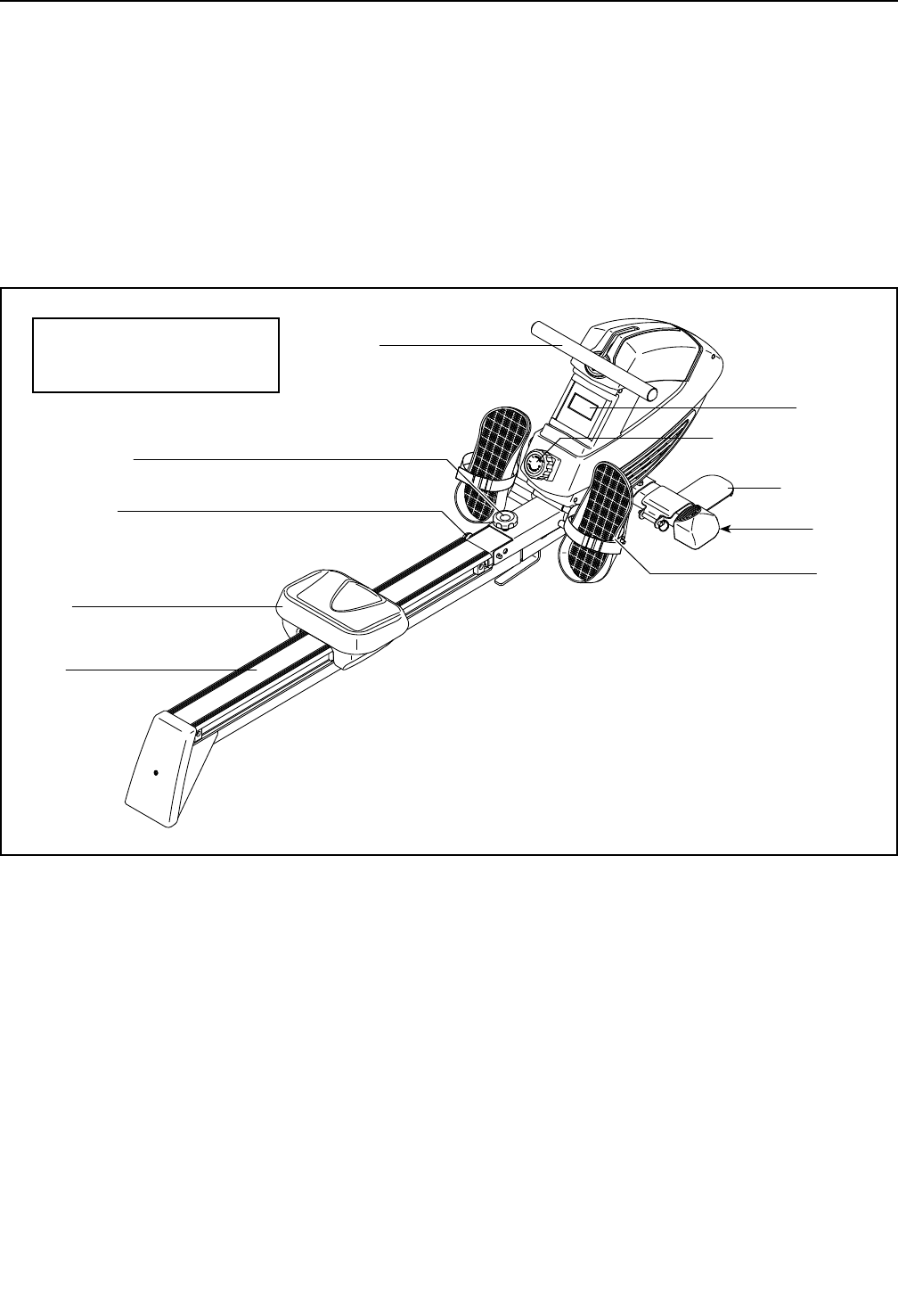
Before reading further, please review the drawing
below and familiarize yourself with the labeled parts.
Foot Plate
Wheel
Pedal
Seat
Console
Resistance Control
Frame Pin
Frame Knob
Rail
Row Bar
BEFORE YOU BEGIN
Length: 6 ft. 3 in. (191 cm)
Width: 2 ft. (60 cm)
6
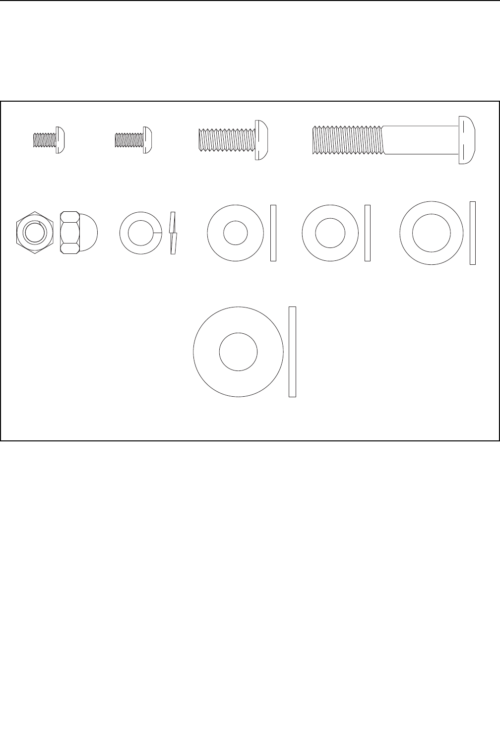
M13 x 32mm
Washer (88)–1
M8 x 20mm
Screw (14)–2
M10 x 52mm
Screw (46)–2
M5 x 8mm
Screw (12)–4
M5 x 10mm
Screw (101)–1
M8 Split
Washer (15)–4
M8 x 20mm
Washer (16)–6
M13 x 22mm
Washer (33)–2
M10 x 20mm
Washer (47)–2
M8 Acorn
Nut (31)–4
PART IDENTIFICATION CHART
Use the drawings below to identify the small parts needed for assembly. The number in parentheses below each
drawing is the key number of the part, from the PART LIST near the end of this manual. The number following the
key number is the quantity needed for assembly. Note: If a part is not in the hardware kit, check to see if it
has been preassembled. Extra parts may be included.
7
• Assembly requires two persons.
• Place all parts in a cleared area and remove the
packing materials. Do not dispose of the packing
materials until you nish all assembly steps.
• To identify small parts, see page 6.
• Left parts are marked “L” or “Left” and right parts
are marked “R” or “Right.”
• Assembly requires only the included tools.
Assembly may be easier if you have a set of
wrenches. To avoid damaging parts, do not use
power tools.
ASSEMBLY
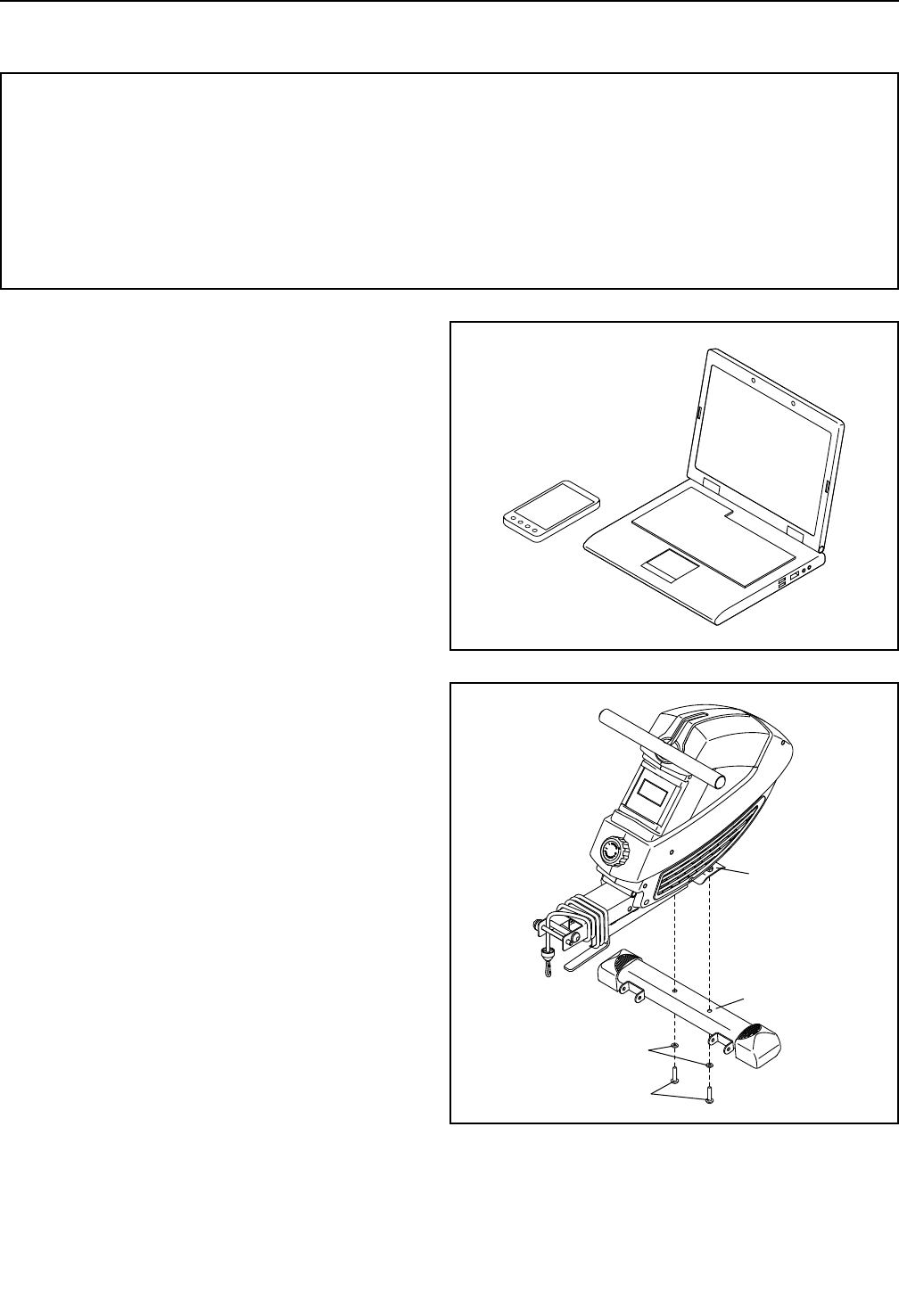
2. Orient the Front Stabilizer (50) as shown.
Attach the Front Stabilizer (50) to the Frame (39)
with two M10 x 52mm Screws (46) and two M10
x 20mm Washers (47).
50
39
47
46
1
2
1. Go to www.iconservice.ca/CustomerService/
registration and register your product.
• activates your warranty
• saves you time if you ever need to contact
Customer Service
• allows us to notify you of upgrades and offers
8
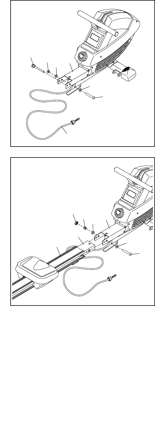
3. Remove the Frame Pin (37) from the Frame (39).
Next, unwrap the Bungee Cord (45) from the
Frame (39).
Then, remove the 1/2" Locknut (54), the two M13
x 22mm Washers (33), and the 1/2" x 100mm
Bolt (36) from the Frame (39).
Note: The parts that you removed will be used in
steps 4 and 5.
45
54 33
33
36
37
3
39
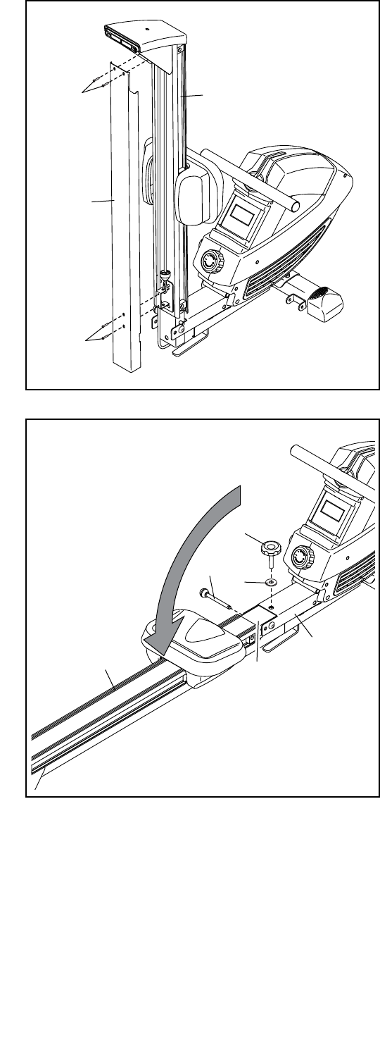
4. Orient the Rail (8) as shown.
Attach the Rail Bracket (41) to the Frame (39)
with the 1/2" x 100mm Bolt (36), the two M13 x
22mm Washers (33), and the 1/2" Locknut (54)
that you removed in step 3.
Then, press the Nut Cap (55) onto the 1/2"
Locknut (54).
4
8
54 33
33
36
41
55
39
9
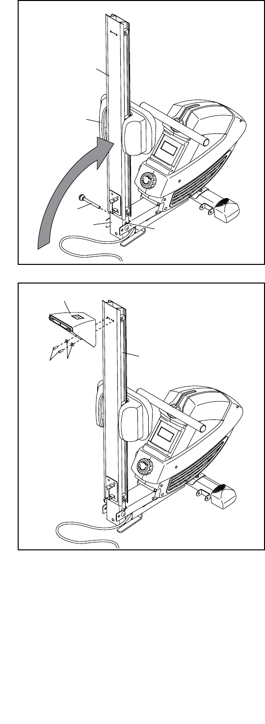
5. Move the Seat (28) to the front of the Rail (8).
Have a second person raise the Rail (8) to the
vertical position. Fully insert the Frame Pin (37)
into the indicated hole in the Rail Bracket (41) so
that it holds the Rail in place. 8
5
3
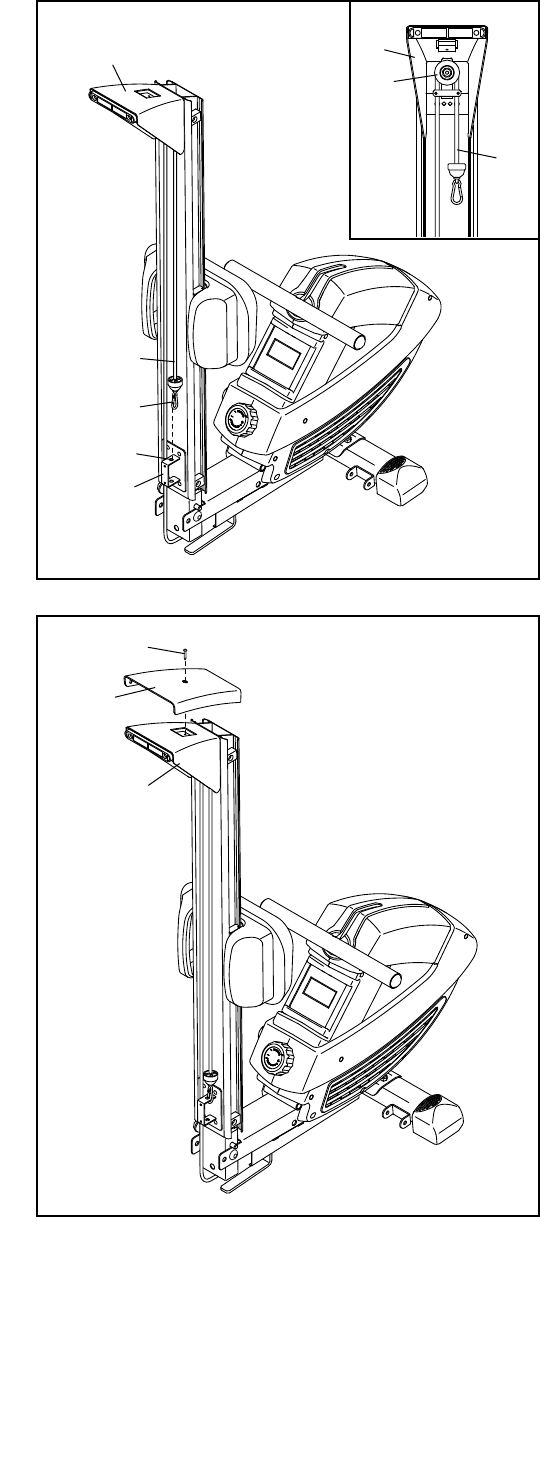
6. Attach the Rear Stabilizer (3) to the Rail (8)
with two M8 x 20mm Screws (14) and two M8 x
20mm Washers (16).
6
28
14 16
37
8
41 Hole
10
8. Attach the Rear Stabilizer Cover (2) to the Rear
Stabilizer (3) with an M5 x 10mm Screw (101). 8101
3
2
7
7. See the inset drawing. Route the end of the
Bungee Cord (45) around the Small Pulley (5) on
the Rear Stabilizer (3) as shown.
Make sure that the Bungee Cord (45) is not
twisted. Attach the Bungee Clip (97) to the indi-
cated hole in the Rail Attachment Bracket (43).
43
45
97
Hole
3
5
45
3
11
10. Remove the Frame Pin (37) from the Rail
Bracket (41), and lower the Rail (8) to the floor.
Next, insert the Frame Pin (37) into the Frame
(39) and into the Rail Bracket (41).
Then, slide an M13 x 32mm Washer (88) onto
the Frame Knob (87), insert the Frame Knob into
the Frame (39), and tighten the Frame Knob into
the Rail Bracket (41).
10
37 88
8
39
87
41
9. Orient the Rail Cover (18) as shown.
Attach the Rail Cover (18) to the Rail (8) with
four M5 x 8mm Screws (12).
9
8
18
12
12
12
12
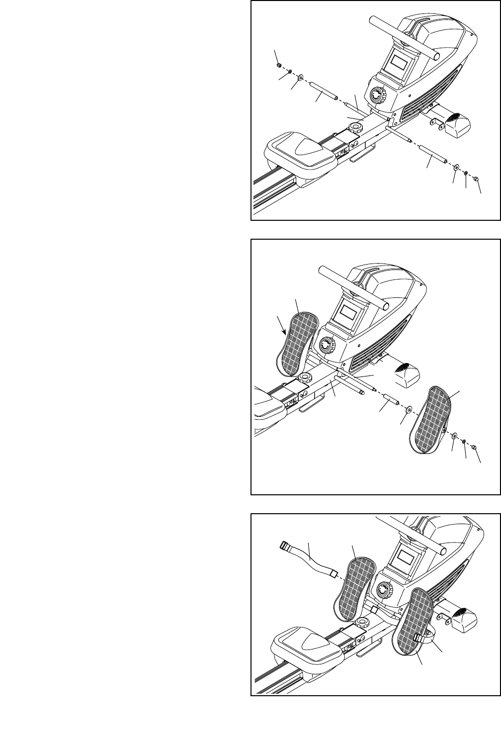
12. Insert the Pedal Axle (58) into the welded tube
on the Frame (39) and center it.
Next, slide a Pedal Spacer (32) and an M13 x
22mm Washer (33) onto each side of the Pedal
Axle (58) (only one side is shown).
Next, identify the Right Pedal (30) and the Left
Pedal (57). Slide the Right Pedal onto the right
side of the Pedal Axle (58), and slide the Left
Pedal onto the left side of the Pedal Axle.
Next, slide an M8 x 20mm Washer (16) and
an M8 Split Washer (15) onto each side of the
Pedal Axle (58) (only one side is shown).
Then, tighten an M8 Acorn Nut (31) onto each
end of the Pedal Axle (58) at the same time.
33
32
15
39
16
30
31
31
57
58
11. Identify the Stop Rod (35), which is slightly
shorter than the Pedal Axle (not shown).
Insert the Stop Rod (35) into the Frame (39) and
center it.
Next, slide a Pedal Stop (34), an M8 x 20mm
Washer (16), and an M8 Split Washer (15) onto
each side of the Stop Rod (35).
Then, tighten an M8 Acorn Nut (31) onto each
end of the Stop Rod (35) at the same time.
11
35
15
15
34
34
39
16
16
31
31
57
30
29
29
13
13. Insert a Pedal Strap (29) through the Right Pedal
(30) as shown. Then, route the end of the Pedal
Strap through the buckle on the Pedal Strap.
Attach the other Pedal Strap (29) to the Left
Pedal (57) in the same way.
13
52
50
51
14
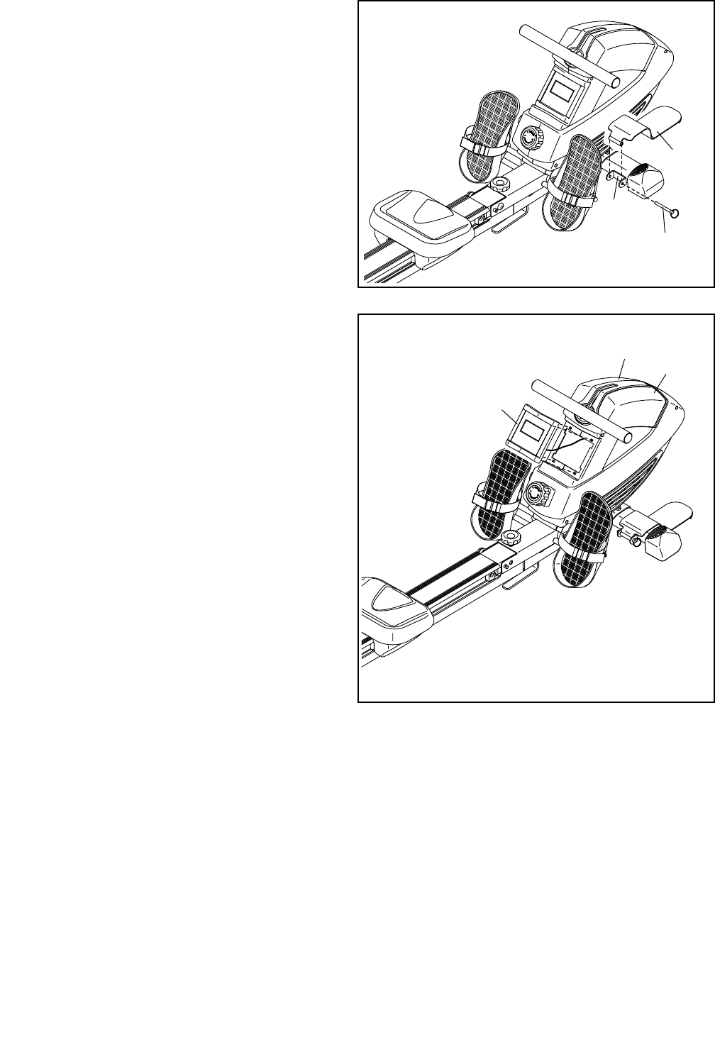
14. Attach a Foot Plate (52) to one side of the Front
Stabilizer (50) with a Foot Plate Pin (51).
Attach the other Foot Plate (not shown) to the
other side of the Front Stabilizer (50) in the
same way.
15
15. The Console (66) requires two AA batteries (not
included); alkaline batteries are recommended.
Do not use old and new batteries together or
alkaline, standard, and rechargeable batter-
ies together. IMPORTANT: If the Console has
been exposed to cold temperatures, allow
it to warm to room temperature before you
insert batteries. Otherwise, you may dam-
age the console display or other electronic
components.
Carefully pry the Console (66) out of the Shields
(44, 69); be careful not to pull on the wire
attached to the Console. Next, remove the
screw (not shown) and the battery cover from
the back of the Console. Insert batteries into the
battery compartment; make sure to orient the
batteries as shown by the diagram inside the
battery compartment. Then, reattach the bat-
tery cover with the screw, and press the Console
into the Shields.
16. Make sure that all parts are properly tightened before you use the rower. Extra parts may be included.
Place a mat under the rower to protect the floor.
66
69
44
14
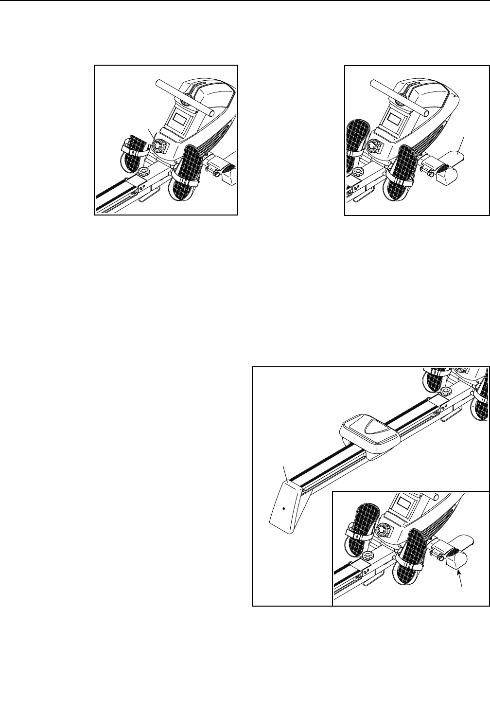
HOW TO ADJUST THE RESISTANCE
To vary the
intensity of your
exercise, you can
adjust the resis-
tance that you
feel when you
pull the row bar.
To increase the
resistance, turn
the resistance
control clockwise;
to decrease the
resistance, turn
the resistance
control coun-
terclockwise. IMPORTANT: To avoid damaging the
resistance control, stop turning it when turning
becomes difficult.
HOW TO ROW ON THE ROWER
Sit on the seat, place your feet in the pedals, and
adjust the straps to fit your feet. Hold the row bar with
an overhand grip.
Correct rowing form consists of three phases:
1. The first phase is the CATCH. Slide the seat
forward until your knees are almost touching your
chest. Pull the row bar until your hands are above
your feet.
2. The second phase is the DRIVE. Push backward
with your legs. Lean back slightly at the hips (not
at the waist), keeping your back straight. As you
straighten your legs, pull the row bar toward your
chest. Keep your elbows outward.
3. The third phase is the FINISH. Your legs should
be nearly straight. Continue to pull the row bar until
your hands are even with your chest.
After the finish phase, extend your arms forward and
pull the seat forward using your legs. Repeat this
sequence, moving through all three phases with a
smooth, fluid motion. Remember to breathe normally
as you row; never hold your breath.
HOW TO DO CURL EXERCISES WITH THE ROWER
Stand on the foot
plates, facing
the rower. Hold
the row bar with
an underhand or
overhand grip.
Next, raise the
row bar until
your hands
are level with
your shoulders.
Keep your
back straight
and keep your
elbows at your sides. Then, lower your hands to the
starting position. Repeat the exercise as many times
as desired.
HOW TO MOVE THE ROWER
Stand behind the rower and lift the rear stabilizer until
the rower will roll on the wheels. Then, carefully move
the rower to the desired location, and lower it to the
floor.
HOW TO USE THE ROWER
Lift
here
Wheel
Foot
Plate
Resistance
Control

15
HOW TO FOLD AND STORE THE ROWER
The rower can be stored in a folded position to con-
serve space. Store the rower in a location where
children cannot tip it. Remove the batteries from the
console when storing the rower for extended periods of
time.
To store the rower, first see assembly step 10 on
page 11. Remove the Frame Knob (87) and the M13
x 32mm Washer (88). Next, remove the Frame Pin
(37). Keep the Frame Knob and the Washer in a place
where they will not become lost.
Next, see assembly step 5 on page 9. Raise
the Rail (8) to the vertical position. Then, fully insert
the Frame Pin (37) into the Rail Bracket (41) so that it
holds the Rail in place.
HOW TO UNFOLD THE ROWER
To unfold the rower, see assembly step 10 on page
11. Remove the Frame Pin (37), and lower the
Rail (8) to the floor. Next, insert the Frame Pin into
the Frame (39) and into the Rail Bracket (41). Then,
tighten the Frame Knob (87) and the M13 x 32mm
Washer (88) into the Frame and into the Rail Bracket.
16
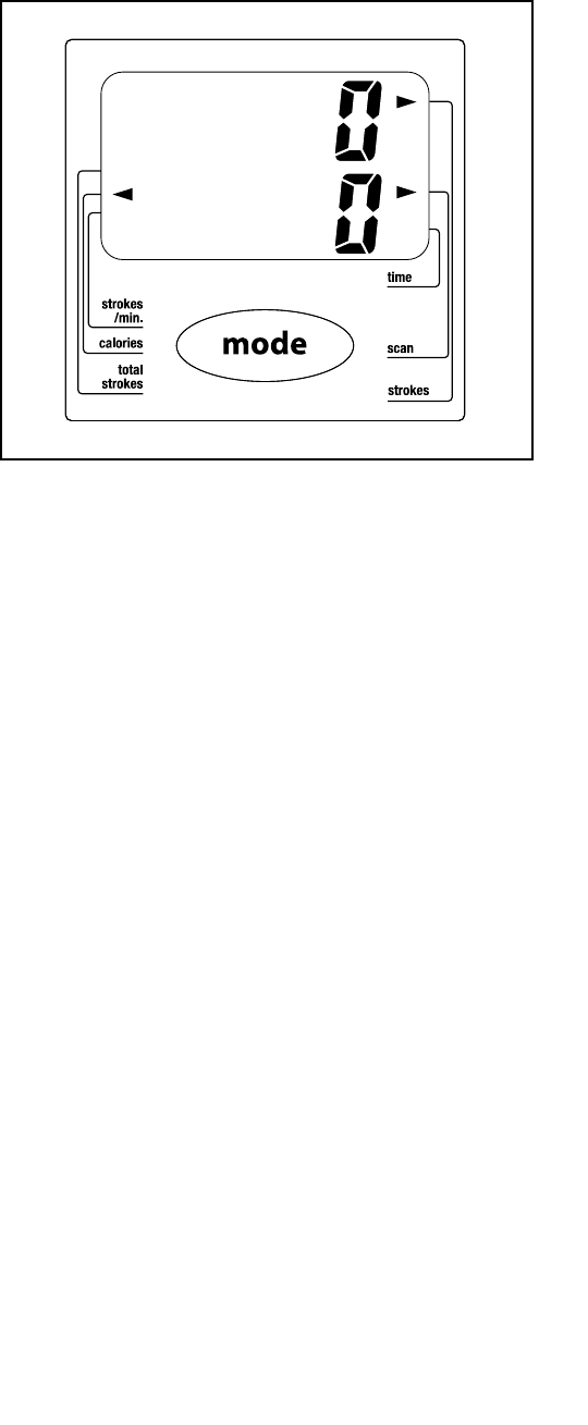
FEATURES OF THE CONSOLE
The easy-to-use console features several display
modes that provide instant exercise feedback dur-
ing your workouts. The display modes are described
below.
Strokes/Min.—This mode shows the number of rowing
strokes you are completing per minute.
Calories—This mode shows the approximate number
of calories you have burned during your workout.
Total Strokes—This mode shows the total number of
rowing strokes you have completed since the console
was last reset. Note: To reset the console, remove the
batteries from the console and then reinsert them.
Time—This mode shows the elapsed time.
Scan—This mode shows the time, strokes, total
strokes, calories, and strokes per minute modes, for a
few seconds each, in a repeating cycle.
Strokes—This mode shows the number of rowing
strokes you have completed during your workout.
HOW TO USE THE CONSOLE
Make sure that batteries are installed in the console
(see assembly step 15 on 13). If there is a sheet of
clear plastic on the console, remove the plastic.
1. Turn on the console.
To turn on the console, press the Mode button on
the console or simply begin rowing.
2. Select one of the display modes.
Scan mode—To select the scan mode, press the
Mode button repeatedly until an arrow appears
next to the Scan label.
Strokes per minute, calories, total strokes, time,
or strokes—To select one of these modes for
continuous display, press the Mode button repeat-
edly until an arrow appears next to the label for the
desired mode. Make sure that an arrow does not
appear next to the Scan label.
3. Begin rowing and follow your progress with the
display.
As you exercise, the console will display the mode
that you select.
To reset the display to zero, press and hold the
Mode button for several seconds.
4. When you are finished exercising, the console
will turn off automatically.
If the row bar does not move for a few seconds, the
console will pause.
The console has an auto-off feature. If the row bar
does not move and the Mode button is not pressed
for a few minutes, the power will turn off automati-
cally to save the batteries.
17
MAINTENANCE
Inspect and tighten all parts of the rower regularly.
Replace any worn parts immediately.
To clean the rower, use a damp cloth and a small
amount of mild detergent. IMPORTANT: To avoid
damage to the console, keep liquids away from
the console and keep the console out of direct
sunlight.
CONSOLE TROUBLESHOOTING
Most console problems are the result of low batteries;
for replacement instructions, see assembly step 15 on
page 13.
HOW TO GREASE THE PEDAL AXLE
If the pedals squeak when you use the rower, see
assembly step 12 on page 12. Remove the Right
and Left Pedals (30, 57), and apply a small amount
of the included grease to both sides of the Pedal Axle
(58). Then, reattach the Pedals.
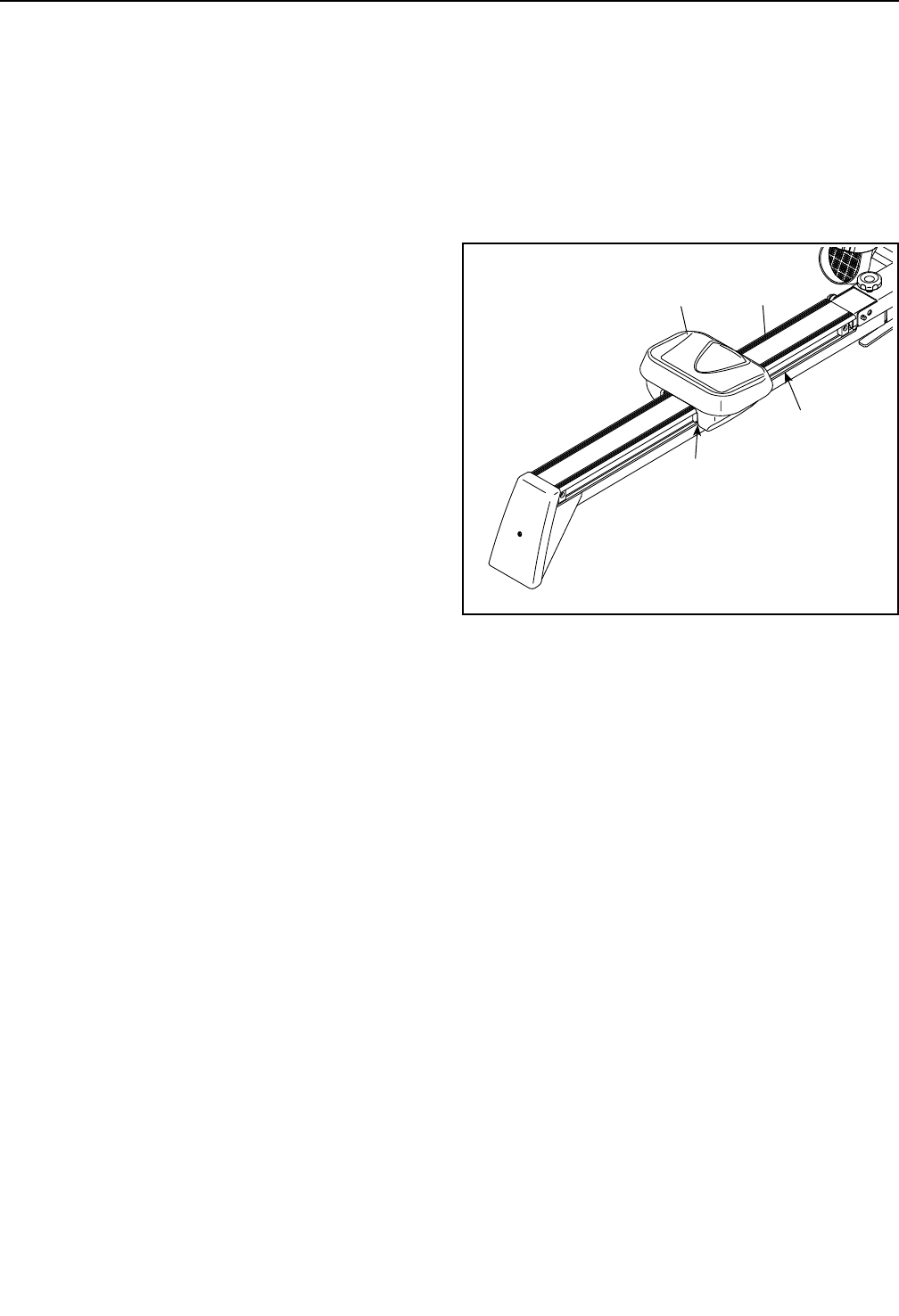
HOW TO GREASE THE ROLLERS
If the rollers beneath the seat squeak when you use
the rower, apply a small amount of the included grease
to a paper towel, and spread a thin layer evenly along
the rail where the rollers move. Then, wipe off any
excess grease.
MAINTENANCE AND TROUBLESHOOTING
Grease
Roller
Seat Rail
18
These guidelines will help you to plan your exercise
program. For detailed exercise information, obtain a
reputable book or consult your physician. Remember,
proper nutrition and adequate rest are essential for
successful results.
EXERCISE INTENSITY
Whether your goal is to burn fat or to strengthen your
cardiovascular system, exercising at the proper inten-
sity is the key to achieving results. You can use your
heart rate as a guide to find the proper intensity level.
The chart below shows recommended heart rates for
fat burning and aerobic exercise.
To find the proper intensity level, find your age at the
bottom of the chart (ages are rounded off to the near-
est ten years). The three numbers listed above your
age define your “training zone.” The lowest number is
the heart rate for fat burning, the middle number is the
heart rate for maximum fat burning, and the highest
number is the heart rate for aerobic exercise.
Burning Fat—To burn fat effectively, you must exer-
cise at a low intensity level for a sustained period of
time. During the first few minutes of exercise, your
body uses carbohydrate calories for energy. Only after
the first few minutes of exercise does your body begin
to use stored fat calories for energy. If your goal is to
burn fat, adjust the intensity of your exercise until your
heart rate is near the lowest number in your training
zone. For maximum fat burning, exercise with your
heart rate near the middle number in your training
zone.
Aerobic Exercise—If your goal is to strengthen your
cardiovascular system, you must perform aerobic
exercise, which is activity that requires large amounts
of oxygen for prolonged periods of time. For aerobic
exercise, adjust the intensity of your exercise until your
heart rate is near the highest number in your training
zone.
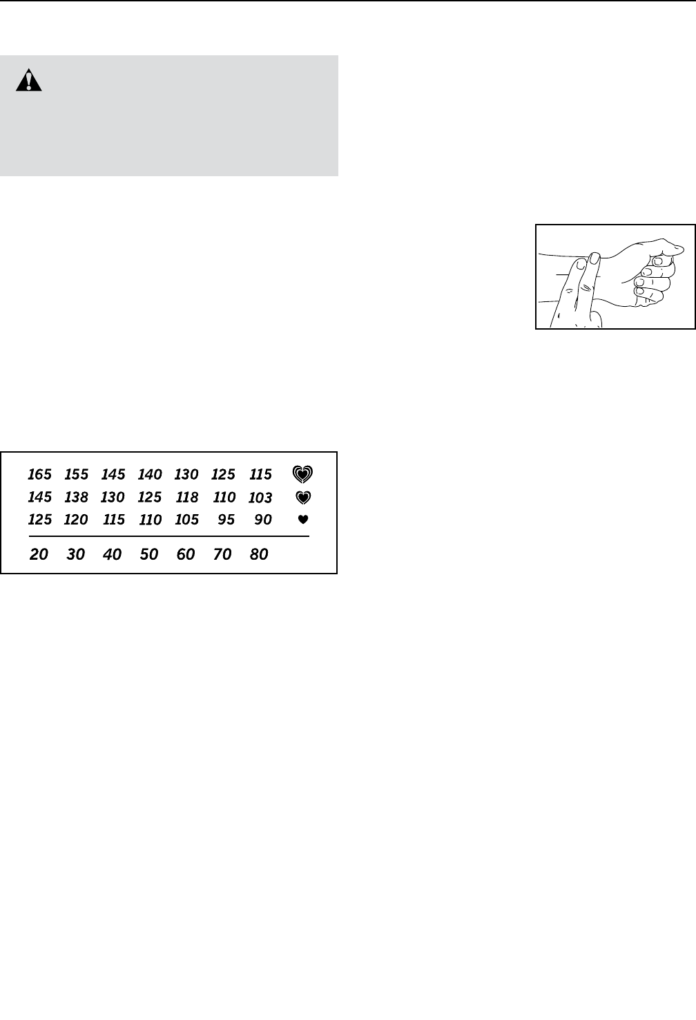
HOW TO MEASURE YOUR HEART RATE
To measure your heart
rate, exercise for at least
four minutes. Then, stop
exercising and place
two fingers on your
wrist as shown. Take a
six-second heartbeat
count, and multiply the
result by 10 to find your heart rate. For example, if your
six-second heartbeat count is 14, your heart rate is 140
beats per minute.
WORKOUT GUIDELINES
Warming Up—Start with 5 to 10 minutes of stretch-
ing and light exercise. A warm-up increases your body
temperature, heart rate, and circulation in preparation
for exercise.
Training Zone Exercise—Exercise for 20 to 30 min-
utes with your heart rate in your training zone. (During
the first few weeks of your exercise program, do not
keep your heart rate in your training zone for longer
than 20 minutes.) Breathe regularly and deeply as you
exercise; never hold your breath.
Cooling Down—Finish with 5 to 10 minutes of stretch-
ing. Stretching increases the flexibility of your muscles
and helps to prevent post-exercise problems.
EXERCISE FREQUENCY
To maintain or improve your condition, complete three
workouts each week, with at least one day of rest
between workouts. After a few months of regular exer-
cise, you may complete up to five workouts each week,
if desired. Remember, the key to success is to make
exercise a regular and enjoyable part of your everyday
life.
WARNING: Before beginning this
or any exercise program, consult your physi-
cian. This is especially important for persons
over age 35 or persons with pre-existing
health problems.
EXERCISE GUIDELINES
19
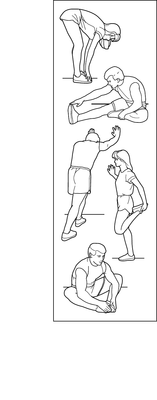
SUGGESTED STRETCHES
The correct form for several basic stretches is shown at the right. Move slowly as you stretch; never bounce.
1. Toe Touch Stretch
Stand with your knees bent slightly and slowly bend forward from
your hips. Allow your back and shoulders to relax as you reach down
toward your toes as far as possible. Hold for 15 counts, then relax.
Repeat 3 times. Stretches: Hamstrings, back of knees and back.
2. Hamstring Stretch
Sit with one leg extended. Bring the sole of the opposite foot toward
you and rest it against the inner thigh of your extended leg. Reach
toward your toes as far as possible. Hold for 15 counts, then relax.
Repeat 3 times for each leg. Stretches: Hamstrings, lower back and
groin.
3. Calf/Achilles Stretch
With one leg in front of the other, reach forward and place your
hands against a wall. Keep your back leg straight and your back foot
flat on the floor. Bend your front leg, lean forward and move your
hips toward the wall. Hold for 15 counts, then relax. Repeat 3 times
for each leg. To cause further stretching of the achilles tendons,
bend your back leg as well. Stretches: Calves, achilles tendons and
ankles.
4. Quadriceps Stretch
With one hand against a wall for balance, reach back and grasp one
foot with your other hand. Bring your heel as close to your buttocks
as possible. Hold for 15 counts, then relax. Repeat 3 times for each
leg. Stretches: Quadriceps and hip muscles.
5. Inner Thigh Stretch
Sit with the soles of your feet together and your knees outward.
Pull your feet toward your groin area as far as possible. Hold for 15
counts, then relax. Repeat 3 times. Stretches: Quadriceps and hip
muscles.
1
2
3
4
5

20
NOTES

21
Key No. Qty. Description Key No. Qty. Description
1 4 M2.5 x 10mm Screw
2 1 Rear Stabilizer Cover
3 1 Rear Stabilizer
4 1 Reed Switch
5 3 Small Pulley
6 1 M10 x 30mm Screw
7 1 Rail Bracket Cap
8 1 Rail
9 2 M6 x 12mm Screw
10 4 Carriage Bumper
11 4 Frame Bushing
12 6 M5 x 8mm Screw
13 1 Rear Foot
14 6 M8 x 20mm Screw
15 12 M8 Split Washer
16 14 M8 x 20mm Washer
17 4 M4 x 12mm Screw
18 1 Rail Cover
19 1 Carriage Cover
20 6 M6 Split Washer
21 6 M6 Washer
22 1 Seat Carriage
23 4 M8 x 32mm Screw
24 4 Roller
25 1 Shield Cover
26 1 Grommet
27 6 M8 Locknut
28 1 Seat
29 2 Pedal Strap
30 1 Right Pedal
31 4 M8 Acorn Nut
32 2 Pedal Spacer
33 4 M13 x 22mm Washer
34 2 Pedal Stop
35 1 Stop Rod
36 1 1/2" x 100mm Bolt
37 1 Frame Pin
38 6 M6 x 16mm Screw
39 1 Frame
40 1 Frame Foot
41 1 Rail Bracket
42 1 Rail Cap
43 1 Rail Attachment Bracket
44 1 Right Shield
45 1 Bungee Cord
46 2 M10 x 52mm Screw
47 5 M10 x 20mm Washer
48 14 M4 x 20mm Screw
49 1 Left Stabilizer Cap
50 1 Front Stabilizer
51 2 Foot Plate Pin
52 2 Foot Plate
53 1 Frame Cover
54 1 1/2" Locknut
55 1 Nut Cap
56 1 Right Stabilizer Cap
57 1 Left Pedal
58 1 Pedal Axle
59 2 M10 x 48mm Screw
60 2 Large Pulley
61 2 M3 x 10mm Screw
62 5 M10 Locknut
63 1 Magnet Spring
64 1 C-magnet
65 2 M8 x 16mm Screw
66 1 Console
67 1 Console Bezel
68 1 M5 x 12mm Washer
69 1 Left Shield
70 1 Spool Bushing
71 2 6001 Bearing
72 2 C-clip
73 1 Flywheel Axle
74 1 6904 Bearing
75 1 Coaster Bearing
76 1 Flywheel
77 1 Spool
78 3 6mm Bushing
79 1 Cord
80 2 13.5mm Bushing
81 1 Foam Grip
82 2 Row Bar Cap
83 1 Row Bar
84 1 Reed Switch Bracket
85 1 Tension Pulley Bracket
86 1 Tension Spring
87 1 Frame Knob
88 1 M13 x 32mm Washer
89 1 Resistance Control
90 1 M5 x 35mm Screw
PART LIST Model No. PFRW3914C.0 R0714A

22
Key No. Qty. Description Key No. Qty. Description
91 2 M5 Nut
92 1 M10 x 68mm Screw
93 2 M4 x 8mm Screw
94 1 M10 Washer
95 1 Bungee End
96 1 Bungee Cover
97 1 Bungee Clip
98 4 M8 Washer
99 1 M10 x 36mm Screw
100 1 M5 x 60mm Screw
101 1 M5 x 10mm Screw
102 2 M4 x 12mm Machine Screw
103 1 Rail Plate
* – User’s Manual
Note: Specications are subject to change without notice. For information about ordering replacement parts, see
the back cover of this manual. *These parts are not illustrated.
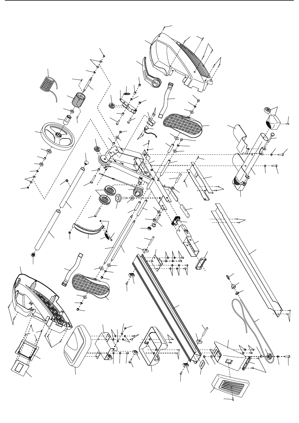
23
EXPLODED DRAWING
3
6
5
8
10
10
10
101
103
10
93
93
102
12
12
12
5
5
2
4
9
9
11
11
11
14
14
16
20
20
14
18
19
13
15
15
15
1
715
15
15
16
16
16
15
17
17
28
31
31
31
31
32
32
25
22
24 27
34
34
36
38
38
39
33
33
35
37
40
41
43
46
46
48
50
52
42
44
47
47
47
49
47
51
54
56
58
59
59
53
55
57
60
61
100
68
63
62
62
62
66
65
65
62
62
64
67
69
70
72
72
71
71
74
76
78
78
78
79
73
75
77
80 82
80
81
83
86
88 85
84
87
89
90
92
91
94
96
98
98
21
21
99
95
97
48
48
48
48
48
48
33
33
16
16
16
16
45
23
30
29
29
27
27
82
47
26
Model No. PFRW3914C.0 R0714A

Part No. 358319 R0714A Printed in China © 2014 ICON Health & Fitness, Inc.
To order replacement parts, please see the front cover of this manual. To help us assist you, be prepared to
provide the following information when contacting us:
• the model number and serial number of the product (see the front cover of this manual)
• the name of the product (see the front cover of this manual)
• the key number and description of the replacement part(s) (see the PART LIST and the EXPLODED DRAWING
near the end of this manual)
ORDERING REPLACEMENT PARTS
ICON of Canada, Inc. (ICON) warrants this product to be free from defects in workmanship and material,
under normal use and service conditions. The frame is warranted for ve (5) years from the date of pur-
chase. Parts and labor are warranted for ninety (90) days from the date of purchase.
This warranty extends only to the original purchaser (customer). ICON’s obligation under this warranty is
limited to repairing or replacing, at ICON’s option, the product through one of its authorized service centers.
All repairs for which warranty claims are made must be preauthorized by ICON. If the product is shipped
to a service center, freight charges to and from the service center will be the customer’s responsibility. If
replacement parts are shipped while the product is under warranty, the customer will be responsible for a
minimal handling charge. For in-home service, the customer will be responsible for a minimal trip charge.
This warranty does not extend to freight damage to the product. This warranty will automatically be voided
if the product is used as a store display model, if all instructions in this manual are not followed, if the prod-
uct is abused or improperly or abnormally used, or if the product is used for commercial or rental purposes.
No other warranty beyond that specically set forth above is authorized by ICON.
ICON is not responsible or liable for indirect, special, or consequential damages arising out of or in con-
nection with the use or performance of the product; damages with respect to any economic loss, loss of
property, loss of revenues or prots, loss of enjoyment or use, or costs of removal or installation; or other
consequential damages of any kind. Some provinces do not allow the exclusion or limitation of incidental
or consequential damages. Accordingly, the above limitation may not apply to the customer.
The warranty extended hereunder is in lieu of any and all other warranties, and any implied warranties of
merchantability or tness for a particular purpose are limited in their scope and duration to the terms set
forth herein. Some provinces do not allow limitations on how long an implied warranty lasts. Accordingly,
the above limitation may not apply to the customer.
This warranty provides specic legal rights; the customer may have other rights that vary from province
to province.
ICON of Canada, Inc., 900 de l’Industrie, St. Jérôme, QC J7Y 4B8
LIMITED WARRANTY
IMPORTANT: To protect your fitness equipment with an extended service plan, see page 4.
