Profoto RMI 2.4 GHz Transceiver Module User Manual Promote RMI Integration Manual
Profoto AB 2.4 GHz Transceiver Module Promote RMI Integration Manual
Profoto >
User Manual

Promote RMI
Integration Manual

Promote RMI
2
www.profoto.com

Promote RMI
3
www.profoto.com
Thank you for choosing Profoto
Thank you for giving us your confidence by investing in the
Profoto Promote RMI. For more than three decades we have
sought after the perfect light. What drives us is our conviction
that we can offer even better tools for the most demanding
photographers. Before our products are shipped we have
them pass an extensive and strict testing program. We make
sure that each individual product meets our high demands
on performance, quality, and safety. For this reason our flash
equipment is widely used in rental studios in Paris, London,
New York, and Tokyo and is also the most rented flash all over
the world.
Some photographers can tell just from seeing a picture,
if Profoto equipment has been used
Professional photographers around the world have come to value
Profoto’s expertise in lighting and light-shaping. Our extensive
range of Light Shaping Tools offers photographers unlimited
possibilities for creating and adjusting their own light.
Every single reflector and accessory creates its special light and
the unique Profoto focusing system offers you the possibility to
create your own light with only a few different reflectors.
Enjoy your Profoto product!

Promote RMI
4
www.profoto.com
NOTE ABOUT RF!
This equipment makes use of the radio spectrum and emits radio frequency energy. Proper care
should be taken when the device is integrated in systems. Make sure that all specifications within
this document are followed, especially those concerning operating temperature and supply voltage
range. Make sure the device is operated according to local regulations. The frequency spectrum
this device is using is shared with other users. Interference can not be ruled out.
SAFETY PRECAUTIONS!
Do not attempt to operate the equipment before studying the instruction manual and the accompanying
safety instructions. Failure to do so may result in serious injuries.
Make sure that Profoto Safety Instructions is always accompanied the equipment!
Profoto products are intended for professional use!
Do not place or use the equipment where it can be exposed to moisture, extreme electro-
magnetic fields, or in areas with flammable gases or dust!
Do not expose the equipment to rapid temperature changes in humidity conditions as this could lead to
water condensation in the unit.
Equipment must only be serviced by authorized and competent service personnel!
Any modifications will break the modular certification and require the module to be re-certified.
FINAL DISPOSAL
This equipment contains electrical and electronic components that could be harmful to the
environment.
Equipment may be returned to Profoto distributors free of charge for recycling according to WEEE.
Follow local legal requirements for separate disposal of waste, for instance WEEE directive for electrical
and electronic equipment on the European market, when the product ‘s life has ended!
Safety instructions

Promote RMI
5
www.profoto.com
Table of Contents
Introduction ......................................................................................................6
General Description ..................................................................................................6
System Diagram ..........................................................................................6
Hardware Description ...............................................................................................7
Mechanical Characteristics ..........................................................................7
Electrical Characteristics .............................................................................8
Pin Out ...........................................................................................8
Recommended Operating Conditions ..............................................8
Interface Description ....................................................................................9
UART Serial Interface ......................................................................9
Reset Interface ...............................................................................9
RF Characteristics......................................................................................10
Important Integration Notes ....................................................................................10
Mechanical Integration ..............................................................................10
Electrical Integration ..................................................................................11
Antenna Integration ...................................................................................11
Regulatory Information .......................................................................................... 12
Certification ...............................................................................................12
Europe ..........................................................................................12
EU Declaration of Conformity ........................................................13
United States and Canada.............................................................14
Japan ...........................................................................................15
Promote RMI
6
www.profoto.com
Introduction
Promote RMI is the base for Profoto’s versatile modular communication platform, used
in products such as the flash generator Pro-8a 1200 Air. It utilzes communication in the
2.4GHz ISM- band and has an impressive performance with a range of up to 300 meters.
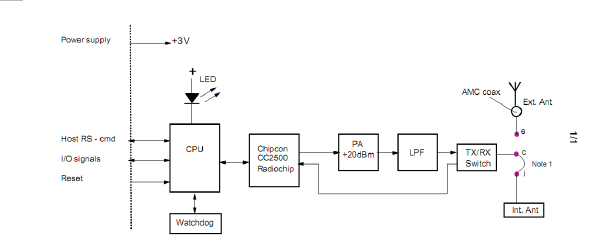
General Description
The Promote RMI module is powered by an 8-bit micro processor with a radio transceiver
from Chipcon and features a complete feature set for wireless interaction with the Profoto
Air range of professional studio equipment. The module has a 3V UART for interaction with
a wide range of devices including computers and other microcontrollers.
System Diagram
Promote RMI
7
www.profoto.com
Hardware Description
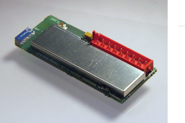
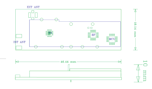
Mechanical Characteristics
Dimensions
46x 18 x 10 mm +/- 1mm [Length, Width, Height]
Weight: approx 10g
Product Image
Promote RMI
8
www.profoto.com
Mechanical Drawing
Electrical Characteristics
PINOUT
PIN Function
1 GND
2 VCC (Transmit)
3 Sync O.C.
4 Test_0
5 Trig
6 N.C.
7 Sync
8 COM TX
9 Reset
10 Test_2
11 Test_3
12 Test_1
13 TTL
14 RMTE
15 COM RX
16 +3V CPU
Promote RMI
9
www.profoto.com
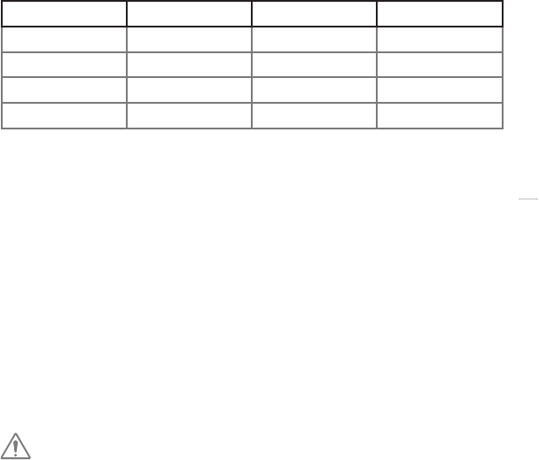
Recommended Operating Conditions
Parameter Min Max Unit
DC Supply 2.7 3.5 V
Current 0.15 A
Temperature -10 +65 °C
Humidity 0 90 % rel n.c
Interface Description
The interface to the host system is implemented as a 16 pin male connector.
The part used on the Promote RMI module is an AMP Micro-MaTch (P/N: 8-215464-6).
The recommended matching female connector is P/N: 8-215079-6. It is recommended
to connect the module with a female header mounted in through holes. This allows for
optimum space saving and leaves the antenna connector easily accessible.
UART Serial Interface
The UART is using pins 1, 8 and 15. To connect to an RS232 line you must use a TTL
level converter (a dongle from B&B Electronics is recommended) from 3.3V or use the
Promote USB dongle which mates with an RMI module and provides a USB interface to
a computer.
Serial characteristics: 38400. 8, N, 1 (no flow control)
NOTE!
Connecting the module to an RS232 line without a line level converter may
damage the module.
For a list of available commands please refer to the RS Toolbox documentation.
Reset Interface
The following conditions will lead to a reset on the Promote RMI module:
• Poweronreset
• Lowvoltage(BrownOut)detectedfrominternalsupervisorycircuit
• ResetbySoftware
• Externalresetthroughresetpin
Promote RMI
10
www.profoto.com
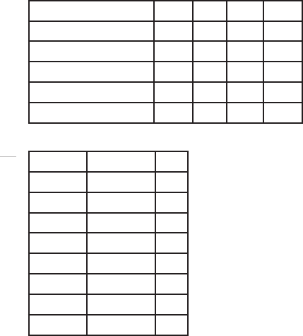
RF Characteristics
Parameter Min Typ. Max Unit
Frequency range 2404 2480 MHz
Frequency stability -25 +25 kHz
Output power EU/US 13 15 17 dBm
Output power Japan 8.1 9.7 10 dBm
Antenna port impedance 50 Ohm
Channel list
Channel Frequency Unit
12403.999 MHz
22411.997 MHz
32416.995 MHz
42421.994 MHz
52426.993 MHz
62446.988 MHz
72453.987 MHz
82479.313 MHz
Important Integration Notes
Promote RMI has been designed to allow for easy integration with a wide range of devices.
There are some key factors you need to consider when integrating the module.
Mechanical Integration
The module needs at least 10 mm clearance in order to fit. This is the maximum height with
consideration to the connector pins. The module has an RF-shield made of nickel silver which
protects all RF-parts (transceiver, power amplifier and VCO). On the module’s backside
there is a test point underneath the antenna which must be protected from user access.
The module should arrive with a label with the serial number printed on it, which should
cover the test point.

Promote RMI
11
www.profoto.com
Electrical Integration
The minimum connections needed for operation are:
PIN Function Comment
1 GND Digital ground
2 VCC Transmit mode
5 Trig Active high
7 Sync Active high
In order to update the firmware the following pins is needed in addition to the ones
mentioned above:
8 COM TX Transmit to host
9 Reset
15 COM RX Receive from host
16 +3V CPU CPU power supply
Antenna Integration
The Promote RMI module is available in two configurations, one with an integrated chip
antenna and one with an external antenna connector. Special care has to be taken when
choosing which option to use and should be done in connection with Profoto. The module
has been certified with an external antenna which is orderable as an option. The use of any
other antenna is not approved and will break the modular approval.
The connector part used on the module is an Amphenol U.FL series, type U.FL SMT,
reference no. A-1JB.
Ready made cable sets are available with the Amphenol connectors already mounted.
Please contact Profoto for accessories. Antenna design is a crucial topic during integration
and design of radio systems. The antenna must provide good omni-directional radiation.
Poor antenna integration may lead to significant degradation of system performance
and / or affect the reliability.

Promote RMI
12
www.profoto.com
Regulatory Information
World-wide Usage of Radio Spectrum
The Promote RMI operates on the license-free 2.4GHz ISM band for SRD (Short Range
Devices). This band may be used in most parts of the world. Regional restrictions may
apply.
All data are to be considered as nominal and Profoto reserves the right to make changes without further notice.
NOTE!
Refer to national regulations for the region where the Promote RMI module
shall be operated and make sure that they are followed.
Europe
Promote RMI has been tested towards ETSI EN 300 328. For each end product- it is required
to perform EMC testing according to ETSI EN 300 489-3. Only limited radio tests will be
required since the modules test report can be applied. Once approved and CE marked,
the system may be sold and used in EU/EEC countries without the need to have country-
specific approval tests. However, a notification procedure is necessary in the member
states of the European Union, this has already been done by Profoto. Please contact Profoto
and we will assist you with conformance testing, approval, and notification procedures.
EU Notification
The Promote RMI has been notified in the EU member states and can be used without
further actions in those countries.

Promote RMI
13
www.profoto.com
EU Declaration of Conformity
In accordance with the Radio and Telecommunications Terminal Equipment Act
and Directive 1999/5/EC (R&TTE Directive)
Manufacturer: Profoto AB
Address: Box 2023, 128 21 SKARPNÄCK, Sweden
Product: 2.4GHz SRD communication module
Type: Promote RMI
Profoto declares that the product complies with the essential requirements of §3 and the other relevant provisions
of the FTEG (Article 3 of the R&TTE Directive) when used for its intended purpose.
Harmonised standards applied:
Air Interface of the radio systems pursuant to article 3(2)
EN 300 328
Protection requirements concerning electromagnetic compatibility according to article 3(1)b:
EN 301 489-1, EN 301 489-17, EN 61000-4-3
Skarpnäck, 2009-01-20
…………………………………………
Bo Dalenius, VP Technology and QA
Profoto AB

Promote RMI
14
www.profoto.com
Unites States and Canada
F.C.C. and Industry Canada
Compliance Statement ( Part 15.19)
This device complies with Part 15 of FCC rules and RSS-210 of Industry Canada.
Operation is subject to the following two conditions:
1) this device may not cause harmful interference and,
2) this device must accept any interference received,
including interference that may cause undesired operation.
Warning (Part 15.21)
Changes or modifications not expressly approved by the party responsible for
compliance could void the user’s authority to operate the equipment.
Ce dispositif est conforme aux normes RSS-210 d’Industrie Canada.
L’utilisation de ce dispositif est autorisée seulement aux conditions suivantes :
1)il ne doit pas produire de brouillage et
2)l’utilisateur du dispositif doit être prêt à accepter tout brouillage radioélectrique reçu,
même si ce brouillage est susceptible de compromettre le fonctionnement du dispositif.
The term ‘IC’ before the certification/registration number only signifies that the Industry
Canada technical specifications were met.
Les lettres ‘IC’ n’ont aucune autre signification ni aucun autre but que d’identifier ce qui
suit comme le numéro de certification/d’enregistrement d’Industrie Canada.
Profoto AB
Transmitter / Receiver
MODEL: Profoto Air RMI
PRODUCT NO: PNZ1808-0000
FCC ID: W4G-RMI
IC: 8167A-RMI
Made in Sweden

Promote RMI
15
www.profoto.com
Japan
The module has been granted modular approval for sale and operation in Japan.
特定無線設備の種類
Classification of specified radio equipment:
Article 2, Clause 1, Item 19
2.4 GHz Wide Band Low Power Data Communication
上記のとおり、電波法第 38条の 24第 1項の規定に基づく認証を行ったも
のであることを証する。
This is to certify that the above-mentioned certification by type has been granted in
accordance with the provisions of Article 38-24, Paragraph 1 of the Radio Law.
In order to comply with Japanese regulations the output power must be limited to 10 dBm
and any user access to the RF-parts must be hindered by using:
• Anenclosurethatneedsspecialtoolstoopen
• AnRF-shieldthatprotectsthetransceiver,amplifierandVCO.
The product must be labelled with the following registration number:
R 202WW08109201

Profoto AB
P.O. Box 2023
SE-128 21 Skarpnäck
SWEDEN
Phone +46 8 447 53 00
info@profoto.com
www.profoto.com
344091-1-319. Printed in Sweden.