Profoto RMI6 RMI Module User Manual RMI6 Integration Manual
Profoto AB RMI Module RMI6 Integration Manual
Profoto >
Contents
- 1. Integration manual
- 2. Users Manual
Integration manual
Integration Manual
RMI6, V1.2
This document and its contents shall not be reproduced or
transferred in any form without express prior permission.
All rights reserved.
© Profoto AB 2017
Specifications are subject to change without prior notice.
Contents
Integration Manual ........................................................... 1
Contents ............................................................................ 3
Important user information ............................................... 6
NOTE ABOUT RF: ..................................................... 6
SAFETY PRECAUTIONS! ......................................... 6
Introduction ...................................................................... 7
General Description ...................................................... 7
System Diagram ........................................................... 7
Hardware description ....................................................... 8
Mechanical Characteristics .......................................... 8
Dimensions ............................................................... 8
Image ........................................................................ 8
Mechanical Drawing ................................................ 8
Electrical Characteristics .............................................. 9
Pinout ....................................................................... 9
Recommended Operating Conditions .......................... 9
Interface Description .................................................. 10
Connector type ....................................................... 10
UART Serial Interface ........................................... 10
Reset interface ............................................................ 11
RF characteristics ....................................................... 11
Channel list ............................................................. 11
Important Integration Notes ........................................... 12
Mechanical Integration ............................................... 12
Electrical Integration .................................................. 12
Antenna Integration .................................................... 13
Certification information ................................................ 13
CE (EU/EES) .............................................................. 14
FCC (USA) ................................................................. 14
FCC Compliance Statement (Part 15.19) ............... 14
Warning (Part 15.21) .............................................. 14
RF exposure limits ................................................. 14
Integrators responsibilities to comply with FCC and
IC Regulations ........................................................ 15
IMPORTANT NOTE: ............................................ 16
End Product Labeling ............................................. 16
IC Compliance Statement (Canada) ....................... 16
Preface
Thank you for choosing Profoto!
Thanks for showing us your confidence by investing in a
Profoto Air Remote or Profoto Air Sync device. For
more than three decades we have sought the perfect light.
What pushes us is our conviction that we can offer even
yet better tools for the most demanding photographers.
Before our products are shipped we have them pass an
extensive and strict testing program. We check that each
individual product comply with specified performance,
quality and safety. For this reason our flash equipment is
widely used in rental studios in Paris, London, New
York, and Tokyo and also the most rented flash all over
the world.
Some photographers can tell just from seeing a picture, if
Profoto equipment has been used. Professional
photographers around the world have come to value
Profoto’s expertise in lighting and light-shaping. Our
extensive range of Light Shaping Tools offers
photographers unlimited possibilities for creating and
adjusting their own light.
Every single reflector and accessory creates its special
light and the unique Profoto focusing system offers you
the possibility to create your own light with only a few
different reflectors.
Enjoy your Profoto product!
Important user information
NOTE ABOUT RF:
This equipment makes use of the radio spectrum and
emits radio frequency energy. Proper care should be
taken when the device is integrated in systems. Make
sure that all specification within this document are
followed, especially concerning operating temperature
and supply voltage range. Make sure the device is
operated according to local regulations. The frequency
spectrum this device is using is shared with other users.
Interference can not be ruled out.
SAFETY PRECAUTIONS!
Do not attempt to operate the equipment before studying
the instruction manual and the accompanying safety
instructions, failure to do so may result in serious
injuries.
Make sure that Profoto Safety Instructions is always
accompanied the equipment!
Profoto products are intended for professional use!
Do not place or use the equipment where it can be
exposed to moisture, extreme electromagnetic fields or in
areas with flammable gases or dust!
Do not expose the equipment to hasty temperature
changes in humidity conditions as this could lead to
water condensation in the unit.
Equipment must only be serviced by authorized and
competent service personnel!
Any modifications will break the modular certification
and require the module to be re-certified.
Introduction
RMI6 is the base for the next generation of Profoto’s
versatile modular communication platform. It is based on
the communication in the 2.4GHz ISM- band and has
impressive performance with a range of up to 300 meters.
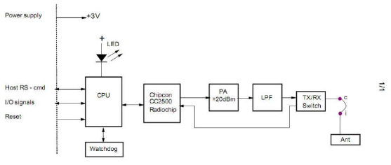
General Description
The RMI6 module is powered by an 8-bit micro
processor with a radio transceiver from Chipcon and
features a complete feature set for wireless interaction
with the Profoto Air range of professional studio
equipment. The module has a 3V UART for interaction
with a wide range of devices including computers and
other microcontrollers.
System Diagram
Hardware description
Mechanical Characteristics
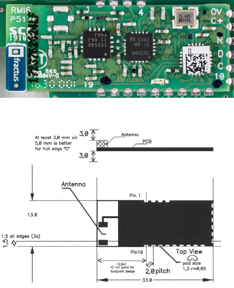
Dimensions
33,0 x 13,0 x 3,0 mm [Length, Width, Height]
Weight approx 10g
Image
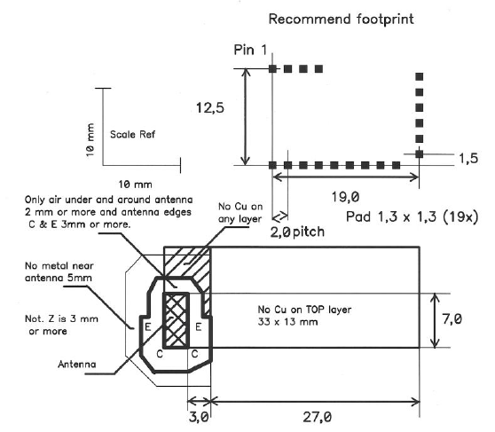
Mechanical Drawing

Electrical Characteristics
Pinout
PIN
1 GND (radio)
2 +3V (radio)
3 TEST_0 in/output
4 SYNC High true, output
5 GND (cpu)
6 +3V (cpu)
7 RESET Low true
8 TEST_2 Flash data
9 TEST_3 Flash clock
10 TRIGG Mx, in/output
11 RMTE in/output
12 TTL Px, in/output
13 SPI_DAI SPI interface. Data input
14 SPI_CS SPI interface, chip select input (low true)
15 COM_RX Serial port, high idle, input
16 COM_TX Serial port, high idle, output
17 SPI_CLK SPI interface, clock input.
18 SPI_DAO SPI interface, data output
19 TEST_1 LED output, low = Light
Recommended Operating Conditions
Parameter
Comment
Min
Max
Unit
DC Supply
2.7
3.3
V
Current
0.15
A
Temperature
-10
+55
°C
Humidity
0
90
%rel, n.c.
Interface Description
Connector type
The interface to the host system is implemented as a 19
solder pads. Please make sure to follow the guidelines for
footprint.
UART Serial Interface
The UART is using pins 1, 15 and 16. To connect to a
RS232 line you must use a TTL converter (a dongle from
B&B Electronics is recommended) from 3V to 12V.
Serial characteristics: 38400. 8, N, 1 (no flow control)

For a list of available commands see the RS Toolbox
documentation.
NOTE!
Connecting the module to a UART port without a line
level converter may damage the module.
Reset interface
The following conditions will lead to a reset on the RMI6
module:
• Power on reset
• Low voltage (Brown Out) detected from internal
supervisory circuit
• Reset by Software
• External reset through reset pin
• Reset by watch dog
RF characteristics
Parameter
Min
Typ.
Max
unit
Frequency range
2404
2479
MHz
Frequency stability
-25
+25
kHz
Output power EU/US
7.9
18.7
18.9
dBm
Output power Asia
6.74
8.11
7.03
dBm
Channel list
Channel
Frequency
Unit
1
2403,999
MHz
2
2411,997
MHz
3
2416,996
MHz
4
2421,994
MHz
5
2426,993
MHz

6
2446,988
MHz
7
2453,987
MHz
8
2479,314
MHz
9
2406,998
MHz
10
2414,996
MHz
11
2429,992
MHz
12
2432,992
MHz
13
2435,991
MHz
14
2438,99
MHz
15
2441,99
MHz
16
2451,321
MHz
17
2456,653
MHz
18
2459,652
MHz
19
2462,318
MHz
20
2465,317
MHz
21
2468,316
MHz
22
2471,316
MHz
Important Integration Notes
RMI6 has been designed to allow for easy integration
with a wide range of devices. There are some key factors
you need to consider when integrating the module.
Mechanical Integration
The module needs at least 3 mm clearance in order to fit..
The module should arrive with a 4x4 mm Data Matrix
label which holds the model number, serial number and
firmware information.
Electrical Integration
The minimum connections needed for operation is:

PIN
Function
Comment
1
GND
Digital ground
2
+VCC
Radio power
8
COM TX
UART output
9
Reset
Active low
12
TTL
Active low
15
COM RX
UART input
Antenna Integration
The RMI6 module is available in one configuration with
an integrated chip antenna. The antenna should not be
modified in any way, doing so will void the approvals for
the module.
Certification information
The module has successfully undergone testing according
to EN 300 328 V2.1.1, FCC 47 CFR Part 15, IC RSS -
247 Issue 2. For end products using the RMI6 module (as
the only radio module), the following applies:
CE (EU/EES)
The RMI6 module is in conformity with the essential
requirements and other relevant requirements of the
Radio Equipment Directive (2014/53/EU).
Please note that every end product using the RMI6
module will need to undergo EMC testing according to
EN 301 489-17 V3.1.1 .
For RF, conduced test results can be inherited from the
RMI6 test report to the end product using RMI6. Limited
EN 300 328 V2.1.1 testing for radiated spurious emission
is necessary and the test must be repeated with the end
product using the RMI6 module.
FCC (USA)
FCC Compliance Statement (Part 15.19)
This device complies with Part 15 of the FCC Rules.
Operation is subject to the following two conditions:
1. This device may not cause harmful interference, and
2. This device must accept any interference received,
including interference that may cause undesired
operation.
Warning (Part 15.21)
Changes or modifications not expressly approved by the
party responsible for compliance could void the user’s
authority to operate the equipment.
RF exposure limits
To comply with FCC/IC RF exposure limits for general
population / uncontrolled exposure, the antenna used for
this transmitter must be installed to provide a separation
distance of at least 20 cm from all persons and must not
be co-located or operating in conjunction with any other
antenna or transmitter.
Cet équipement est conforme aux limites d'exposition
aux rayonnements IC établies pour un
environnement non contrôlé. Cet équipement doit être
installé et utilisé avec un minimum de 20 cm de distance
entre la source de rayonnement et votre corps.
Ce transmetteur ne doit pas etre place au meme endroit
ou utilise simultanement avec un autre transmetteur ou
antenne.
Integrators responsibilities to comply with
FCC and IC Regulations
The RMI6 Module has been certified for integration into
products only by OEM integrators under the following
conditions: 1. The antenna(s) must be installed such that
a minimum separation distance of 20cm is maintained
between the radiator (antenna) and all persons at all
times. 2. The transmitter module must not be co-located
or operating in conjunction with any other antenna or
transmitter.
As long as the two conditions above are met, further
transmitter testing will not be required. However, the
OEM integrator is still responsible for testing their end-
product for any additional compliance requirements
required with this module installed (for example, digital
device emissions, PC peripheral requirements, etc.).
IMPORTANT NOTE:
In the event that these conditions cannot be met (for
certain configurations or co-location with another
transmitter), then the FCC and Industry Canada
authorizations are no longer considered valid and the
FCC ID and IC Certification Number cannot be used on
the final product. In these circumstances, the OEM
integrator will be responsible for re-evaluating the end
product (including the transmitter) and obtaining a
separate FCC and Industry Canada authorization.
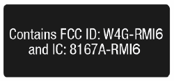
End Product Labeling
The RMI6 module is labeled with its own FCC and IC
ID. If the FCC and IC ID:s is not visible when the
module is installed inside another device, then the outside
of the device into which the module is installed must also
display a fysical label or eLabel referring to the enclosed
module. In that case the end product must be labeled in a
visible area with the following: Contains FCC ID: W4G-
RMI6 and IC: 8167A-RMI6
IC Compliance Statement (Canada)
This Device complies with Industry Canada License-
exempt RSS standard(s). Operation is subject to the
following two conditions:
1) this device may not cause interference, and
2) this device must accept any interference, including
interference that may cause undesired operation of the
device.
Le présent appareil est conforme aux CNR d'Industrie
Canada applicables aux appareils radio
exempts de licence. L'exploitation est autorisée aux deux
conditions suivantes:
(1) l'appareil ne doit pas produire de brouillage, et
(2) l'utilisateur de l'appareil doit accepter tout brouillage
radioélectrique subi, même si le brouillage est susceptible
d'en compromettre le fonctionnement.
Under Industry Canada regulations, this radio transmitter
may only operate using an antenna of a type and
maximum (or lesser) gain approved for the transmitter by
Industry Canada.