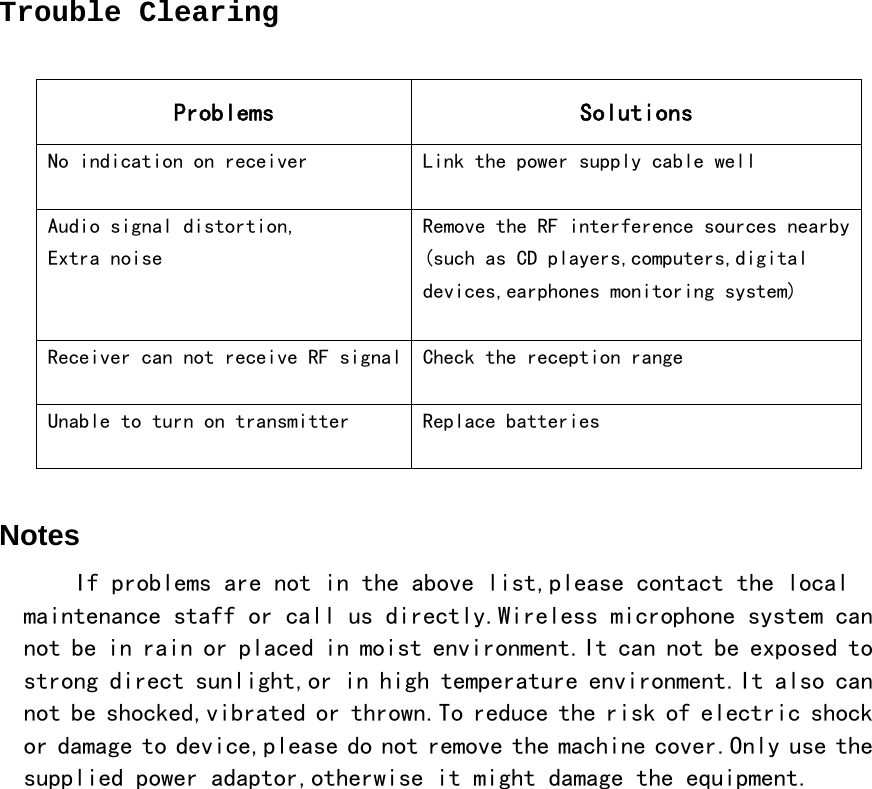
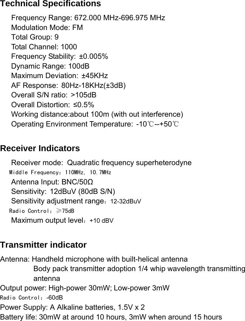
Promark 9E3W1KUH WIRELESS MICROPHONE User Manual

Nady Systems Inc WIRELESS MICROPHONE

Users Manual

              UHF Wireless Microphone Syetem  USER MANUAL
           Welcome to select UHF wireless microphone system, and welcomes you to join our clients team. UHF wireless microphone system is a professional design and production, with the perfect professional sound quality, using the world's most advanced multi-channel digital phase-locked loop of the DPLL frequency synthesis, UHF ultra-high frequency band, the real diversity. Available 9 group, 99-channel selection, can avoid all kinds of interference, the system runs more stable, more reliable transmission. And infrared channels to recover automatically locks and locking systems and other innovative design allows you to more easily use the system, operation is simple and clear. Our ultimate goal is to design the most perfect embodiment of the sound system functions.
Wireless receiver function ☞Wireless receiver control panel Description ⅰReceiver Front panel     ●1 Volume indicator: Has four green and one red light, the number of the green light is means the voice value. If it was red light, then the voice is high enough and distortion, please turn down the value.  ●2 LED :Display group、channel、volume、signal ●3 Function keys:Press SET button to select the main menu one by one in a cycle,press“▲”“▼”button to change or confirm the current state of the selected menu,then press the SET button again to make the setting in effect,hold the “▲”“▼” button for a long time to quickly select the frequency and channel. ●4 Infrared light: When press“ACT”key,The light is working. ●5 Infrared frequency button:press “ACT”button, Channel parameters will be transmitted to the transmitter. ●6 Power on/off Switch:press “POWER”button, Open the receiver power. ⅱ Receiver back panel diagram  ●7 Socket: 12V DC power supply input socket, Socket connection is the center electrode voltage. ●8 Audio Balanced Output: The use of "XLR"-type socket, Two-channel signal separately output.  ●9 Audio Mixed Output: Two signals will be mixed with the output
●10  Antenna Socket:   ☞Receiver LCD Description   ●1 Group menu display: Displays the current working group. ●2 Channel menu display:Indicating that the current operating channel. ●3 Volume menu display:to display volume signals. ●4 Signal menu display: display the current signal strength. ●5 Antennas display.  ☞The Steps of turning on receiver 1. Open the receiver power 2. Then turn on the transmitter,adjust receiver’s volume to a proper level,then make sound towards microphone then we can see microphone volume indication field on receiver’s audio level meter is illuminated.if no audio output,or level meter is not illuminated,please examine the device.  3.When system is not in application for a long period of time,please turn the device off and take out the battery.   ☞Receiver Operating Instruction   Note: After confirm whenever functions are selected to change, LCD screen will be flashing, after 9 second the stop flashing, Change in force,press "SET" button to confirm after the flashing stop.  ⅰ Automatic Frequency Operation
   Press “SET”button ,make transmitter point at receiver’s infrared automatic  freqency  window,and  hold  it  for  2-3  seconds;Receiver’s channel parameters shall be sent to transmitters via infrared data. ⅱ Group settings    Press "SET" button to enable LCD in "GROUP" flashing, And then press "▲" or "▼" button to change the group number, press "SET" button to confirm. (0-9 class has optional). ⅲ Channel settings Press "SET" button to enable LCD in "CHANNEL" flashing, And then press "▲" or "▼" button to change the group number, press "SET" button to confirm. (0-99 class has optional).  ⅳ Volume settings Press "SET" button to enable LCD in "vol" flashing, And then press"▲" or "▼" button to change the volume signals, click "SET" button to confirm. (0-63 class has optional).  Handheld Transmitter Features ☞Handheld Transmitter Control Description Note: how to use the built-in button!                          Picture 1                           Picture 2  Holding hand-held transmitter of the upper part of cylindrical shell (arrows in Picture 1), the arrow shown in Picture 1 spin out of the lower part of shell, as shown in Picture 2 the arrow to pull down, you can reveal a built-in button .
ⅰ Handheld transmitter positive map     ●1 Microphone Head:Includes Microphone grille and microphone capsule. ●2 Tube body: Containing batteries 、transmitter PCB, built-in function keys, built-in transmitting antenna tail. ●3 LCD screen:display Group、Channels and battery. ●4 Up and down select keys (built-in): Press "▲" "▼" button to select the menu on the current state of change, can change the Working Group or Channel.( use same as the receiver) ●5 Settings button (the built-in): Press "SET" key to select the main menu cycle, also can change the settings to confirm. Change the settings if confirmed, LCD screen will be flashing to remind, after 9 seconds flashing to stop, change the entry into force. ●6 Built-in high and low transmission power change-over switch ●7 Power switch: On/OFF  ⅱ Handheld transmitter back of map   ●8 Infrared auto frequency window,by operating “SET” button of receiver,channel parameters shall be sent to transmitter. ●9 Battery Tray
☞ Handheld Transmitter LCD Instruction  ●1 Group display:display the current operating group. ●2 Channel display:display the current operating channel. ●3 Battery display:display the current remaining battery capacity.  Battery Operation Instruction  ☞Handheld transmitter battery installation  1. Holding hand-held transmitter of the upper part of cylindrical shell (arrows in Picture 1), the arrow shown in Picture 1 spin out of the lower part of shell, as shown in Picture 2 the arrow to pull down, exposing the battery positions.                      Picture 1                   Picture 2
 2. Put two new AA alkaline batteries on the 5th. Make sure that the polarity of the battery install (Figure). Warning: Do not install the wrong battery polarity, which may damage electronic components within the transmitter.   3. Afresh spin on transmitter lower part case   ☞Body Pack Transmitter Battery Instruction 1. Soft  depress  battery  cover  on  both  sides, can open the battery warehouse.( following diagram)   2. Put two new AA alkaline batteries on the 5th. Make sure that the polarity of the battery install(Follow the battery polarity warehouses instructions)  3. Cover positions back to the battery cover (Note:When system is not in application for a long period of time,please turn the device off and take out the battery.)
 Notes *Please choose non-intermodulation frequency setting.within 50 MHz bandwidth,Usually 4-8 transmitters can be used at the same time.If more sets of wireless microphones are needed,devices with other frequency band should be applied. *There should be appropriate distance between the receiver and transmitter,not too near,at least 1 meter distance. *If receiving condition seems not to be as good as expected,extended cord,exterior high-gain antenna,and even antenna amplifier can be applied. *The receiver and transmitter must be set the same frequency channel. *When several sets of receivers are used together,it is recommended to use high-gain antenna,antenna amplifier and receive branch unit. *When receiver adopts the omni-directional antenna,please keep the antenna away from the wall at least 0.5 mm,and also away from any other metal objects. *The transmitter should at least 20cm apart when multiple transmitters are used together,so as not to interfere each other *When you use Handheld Microphone,please hold the middle of the mic.Body.If too close to the Microphone grille,it will affect the sound pick-up;if too Close to the antenna (at the bottom of the microphone),transmission efficiency and working distance may be reduced. *Increase and reduce treble or bass by adjust the distance between microphone and mouth. *The Body Pack Transmitter adopts 1/4 wavelength whip antenna,please never let the antenna contact human body directly,nor tie with the microphone caoble together,otherwise it will reduce the operation effects. *To reduce the voice fluctuation when head moves,please keep the collar-worn microphone as close as possible to the middle,and the microphone connections should also be fixed tightly to avoid friction noise. *When collarworn microphone is applied for live sound reinforcement,directional microphone capsule should be used.Selection and position arrangement of speakers should be made in consideration of feedback elimination.When necessary,feedback destoryer should be equipped.
 Trouble Clearing  Problems  Solutions No indication on receiver  Link the power supply cable well Audio signal distortion, Extra noise  Remove the RF interference sources nearby (such as CD players,computers,digital devices,earphones monitoring system)  Receiver can not receive RF signal Check the reception range Unable to turn on transmitter  Replace batteries  Notes       If problems are not in the above list,please contact the local maintenance staff or call us directly.Wireless microphone system can not be in rain or placed in moist environment.It can not be exposed to strong direct sunlight,or in high temperature environment.It also can not be shocked,vibrated or thrown.To reduce the risk of electric shock or damage to device,please do not remove the machine cover.Only use the supplied power adaptor,otherwise it might damage the equipment.
 Technical Specifications    Frequency Range: 672.000 MHz-696.975 MHz    Modulation Mode: FM    Total Group: 9    Total Channel: 1000    Frequency Stability: ±0.005%    Dynamic Range: 100dB    Maximum Deviation: ±45KHz    AF Response: 80Hz-18KHz(±3dB)    Overall S/N ratio: >105dB    Overall Distortion: ≤0.5%    Working distance:about 100m (with out interference) Operating Environment Temperature: -10℃--+50℃  Receiver Indicators    Receiver mode: Quadratic frequency superheterodyne Middle Frequency:110MHz, 10.7MHz    Antenna Input: BNC/50Ω    Sensitivity: 12dBuV (80dB S/N) Sensitivity adjustment range:12-32dBuV Radio Control:≥75dB Maximum output level:+10 dBV  Transmitter indicator Antenna: Handheld microphone with built-helical antenna          Body pack transmitter adoption 1/4 whip wavelength transmitting antenna Output power: High-power 30mW; Low-power 3mW Radio Control:-60dB Power Supply: A Alkaline batteries, 1.5V x 2 Battery life: 30mW at around 10 hours, 3mW when around 15 hours

Navigation menu