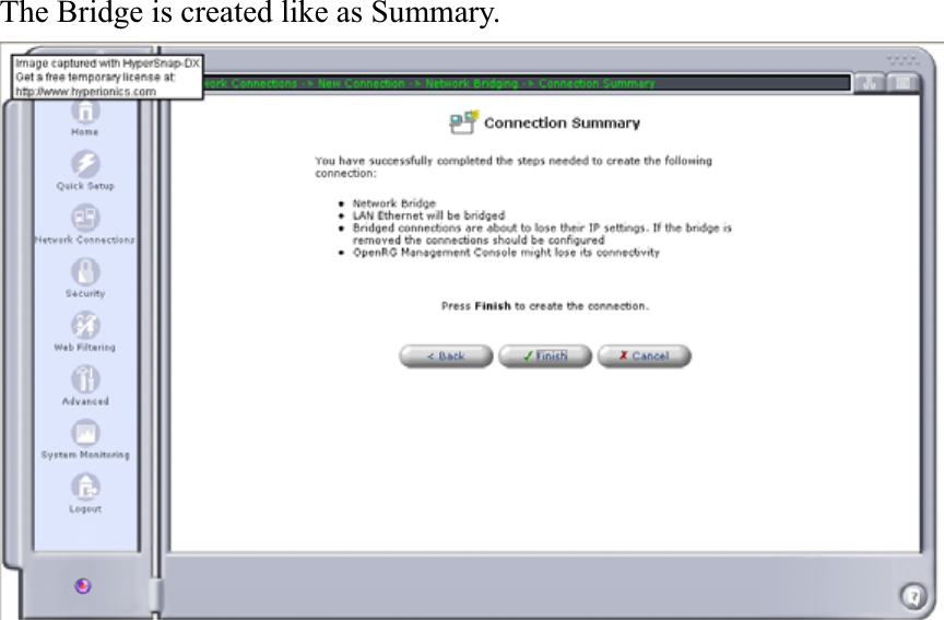
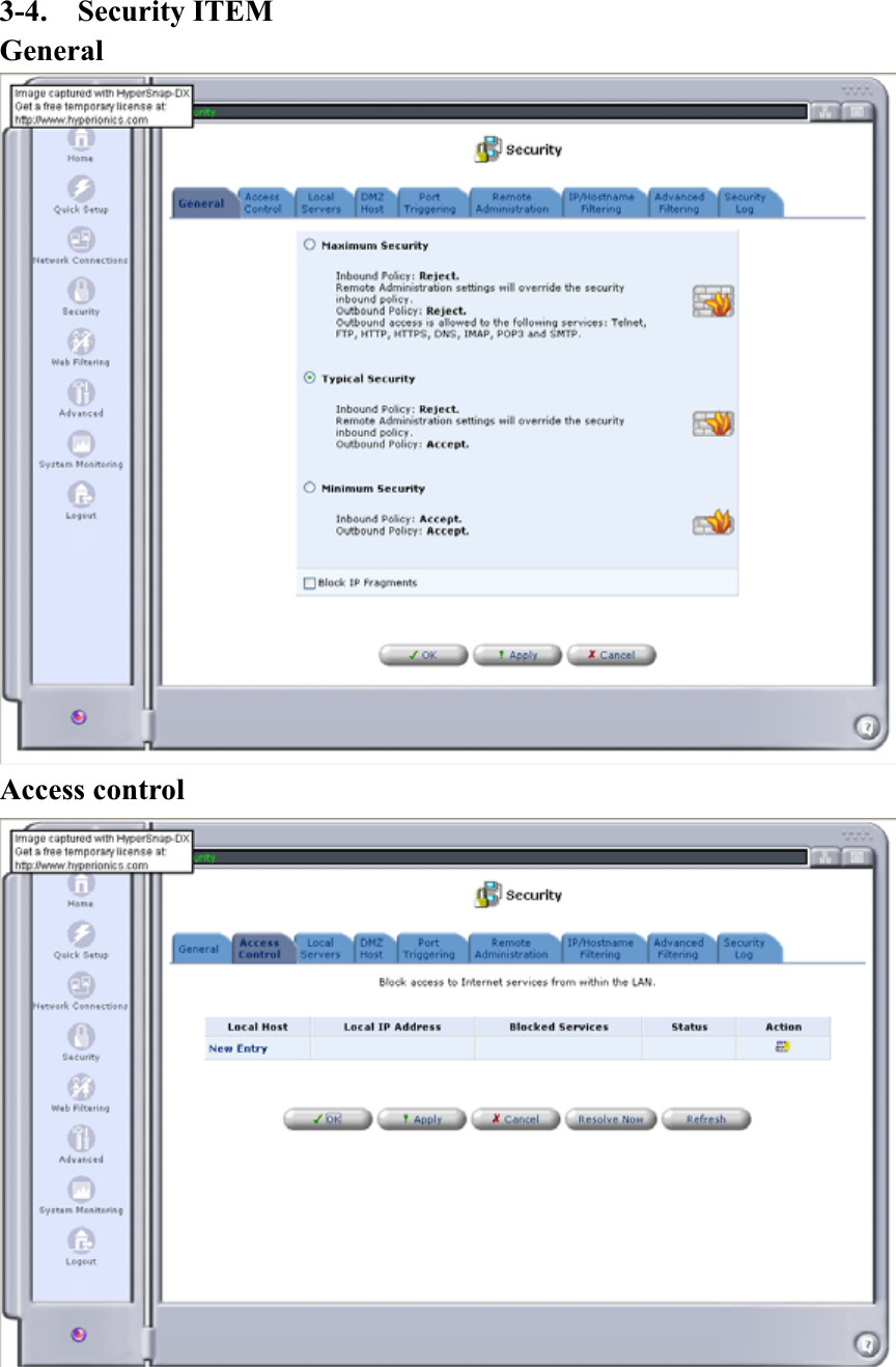
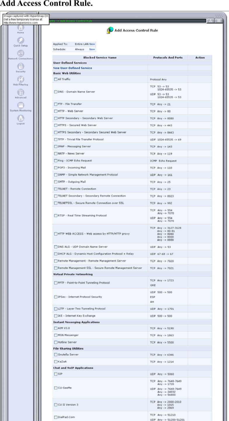
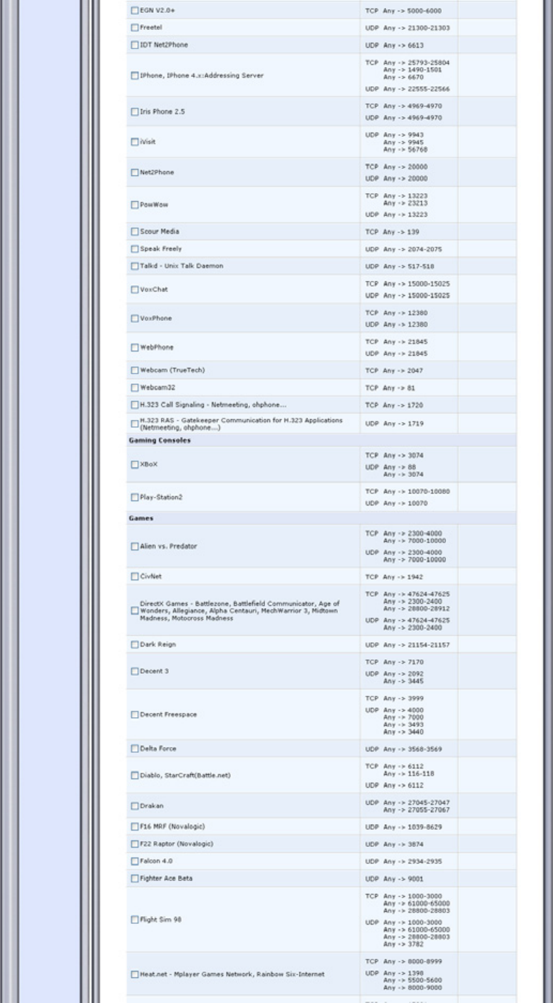
Pronto Networks PN-CPP-A-1422 802.11 b/g Wireless Router User Manual

Pronto Networks, Inc 802.11 b/g Wireless Router

Contents

User Manual 1 of 3

Wireless Router    User Guide Software Version 3.14.40.7.2.1027   The HTML is using Unicode (UTF-8)
ContentsChapter 1.    Before you start to use the router. Chapter 2.    Beginning to use Router by Web GUI Chapter 3.    Operation in GUI 3-1.  Home ITEM. 3-2.    Quick Setup ITEM 3-3.    Network Connections ITEM   3-4.  Security ITEM 3-5.    Web Filtering ITEM 3-6.  Advanced ITEM 3-7.  SYSTEM Monitoring ITEM 3-8.  Logout ITEM Warring Notice.
Chapter 1.   Before you start to use the router. Check those texts on and part of Router to know how to use it. Parts: Power Adapter: AC input 100~240Volts, 1Amp. DC output 12V, 1.5A. Plastic Base: For Router body stand purpose. Put it into router body fillister in the button side. Antenna in the Router:           This antenna can be rotated 180 degree. From down side (line up to the case) to the up side by clock reversing rotation when you are looking it in back panel side. Text: POWER: DC Power socket, to be plug in from power adapter DC plug. SW: Power switch. RESET: Press one shot, the router will restart. Press and hold it more than 5 seconds, the router will return to default setting and restart. WAN: For Ethernet external port. LAN1~4: For Ethernet internal port. USB1~2: For USB interface Printer or Flash disk, if you want to link to small Hard Driver Disk, you should use 2 port both in the same time. The limited current is 1.0A/5V. And the USB port version is 2.0.
Operation sequence: 1.  You need to plug the AC power adapter on AC power socket. 2.  Take its DC plug into Router DC power socket. (“Power”) 3.  Put the power switch (Text “SW”) from low to high position. 4.  Then the router will spend a minute to start. 5.  Power LED and WLAN LED will light until you turn off the power switch.6.  All LAN and WAN LED will blink once and then, starting to check each port, those LED blink one by one. After that, All LWAN and WAN LED shall blink again, finally, it will lights when port has Ethernet signal normal (it means you were put Ethernet cable into router and another side has Ethernet device live.) 7.  If USB port has device insertion, also it will light. 8.  Set your NIC (Network Interface Card) in PC, its IP to the this value: IP: 192.168.0.1 , Mask: 255.255.255.0 , Gateway: 192.168.0.253     (The Router LAN IP is 192.168.0.253) 9.  You can try to use Web Browser (Like as Microsoft IE or Mozilla   Firefox) and type LAN IP which you defined (Default setting is   192.168.0.253) to address bar then press “Enter”.   10. The Web Browser will open the webpage a few seconds. If no, check your physical network condition and TCP/IP setting in your system to debug your connection. (or if you cannot access the Router, Please press Reset-button over than 5 seconds to restore default! (Reset-button is posited between Power socket and LED)) 11.
Chapter 2.   Beginning to use Router by Web GUI When you are first time to login the router by web, you can see the page shows that username and password configuration. Second times later, the Login page just shows username and password.
After login process, the page will show “Quick Setup”. The page (function) is like as ITEM “Quick Setup” in the Left frame.   This is a page guide you to set up the router easily. Select and Type which kind of you need or data input you want. Finally, press “Apply” to save your setting, Press “OK” to lunch it.
Chapter 3.   Operation in GUI 3-1.  Home ITEM. When you press the “Home” icon in the Left frame. The page will shows “Network Map”, the physical link map in the Right frame. Press the small icon to show “Network List View” by TEXT. (See the red circle and line like as graph shows.
3-2. Quick Setup ITEM “Quick Setup” is the first page we show in the Chapter 2.
3-3.  Network Connections ITEM           The page will show network interface and you can add new one in a new connection. To check “WAN Ethernet properties”, press which name in the field or “Action” in the same line end. It is general information of the connection interface. Or you can “Disable” it by the icon.
After press setting, you can see the detail setting webpage “Configure WAN Ethernet” to do configuration that you required. Regarding “LAN Ethernet Properties”, those operations are the same as WAN’s. Or you can “Disable” it by the icon.(CAUTION: If this is only one LAN side connection interface, you will lose the LAN connection Until you restore to default this router.
After press setting, you can see the detail setting webpage “Configure LAN Ethernet” to do configuration that you required.
Wireless Connection: To set up wireless configuration, to select Underlying Device: “LAN Wireless 802.11g Access Point” Then the “LAN Wireless 802.11g Access Point Properties” will shows that. Operate it like as LAN’s.
After press setting, you can see the detail setting webpage “Configure LAN Wireless 802.11g Access Point” to do configuration that you required.
New connection: If you want to add new connection in the router, to where page (3-3.   ITEM “Network Connections”) the press it. First, you shall set the connection type is PPPoE or Network Bridging. To continue PPPoE set process, select the underlying device you define.
Then input your account username and password. Finally, it wills summary connection.
Check the “Network Connection” page, you can see the PPPoE was set in it and in progress. Network Bridging: Choose one for Bridged Connections, then press “Next”
The Bridge is created like as Summary.
3-4.  Security ITEM GeneralAccess control
Add Access Control Rule.

Navigation menu