Protectli FW4B Mini Pc User Manual
Protectli Mini Pc
User Manual
FW4B
Mini Pc
User Manual
Version 1.0
Published May 2018
Content
1. Introduction............................................................................................................................1
1.1 Specification......................................................................................................................2
1.2 Package Contents..........................................................................................................3
1.3 I/O Panel………………………………………………………………………………………………….4
2. Installation..............................................................................................................................4
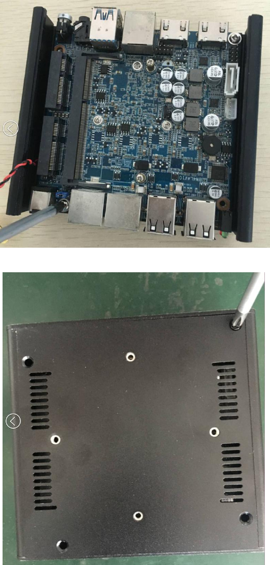
2.1 Screw Holes.......................................................................................................................5
2.2 Pre-installation Precautions..........................................................................................6
2.3 Installation of Memory Modules.............................................................................. 6
2.4Onboard Headers and Connectors........................................................................ 6

Chapter 1: Introduction
1.1Specification
Package Contents
FW4B Main Host
Vesa Bracket
Screw Package
Model FW4B
Processor Intel Celeron J3160(quad core,1.6 GHz, Turbo boost 2.24 GHz)
Chipset Adopt Intel express chipset
RAM 1*SODDR3L(can up to 8G)
Display port Integrated Intel HD Graphic card, Support 2*HDMI
Expansion port 2*Mini-PCIE, support wifi
Storage 1* MINISATA
Audio N/A
Network 4* Intel I210AT 1000M Lan, support wake on lan
I /O
4* RJ-45
1* 12V DC input
2* HDMI
2 *USB 3.0
1*Power switch
1* Power Led, 1* HDD led
Built-in I/O
1 * FP1
1 * J2
1 * JSATA Port, 1*SATA
1 * MINI_PCIE for WiFi, 1 * Mini-SATA
1 * SODIMM
1 * CPU_Fan
BIOS AMI 64M DPI Flash ROM
WDT Support hardware reset (256 level,0~255 sec)
Power supply DC-12V
Temp -20℃~60℃
Humidity 0~95% relative humidity, non-condensing
Dimension 115 * 107.5 * 39 mm
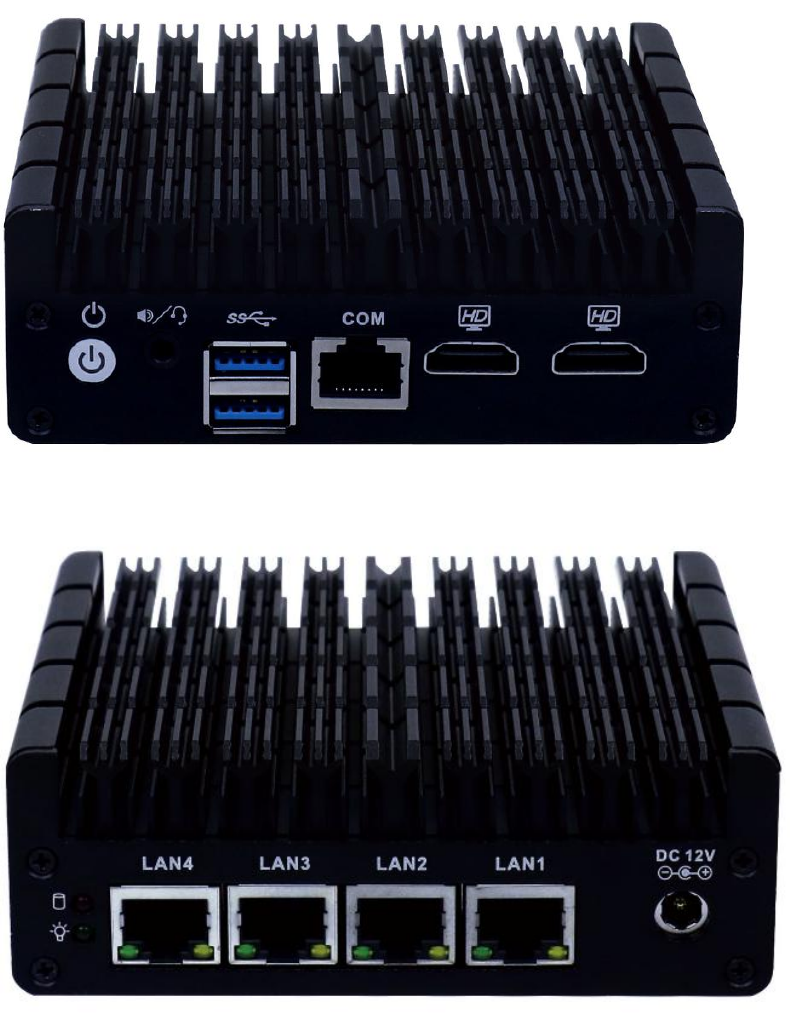
1.3 I/O Panel
Chapter 2
2.1 screw holes
Place screws into the holes to secure the motherboard to the chassis .
Place screws into the hold to secure the bottom panel to the chassis .
2.1 Pre-installation precautions
Take note of the following precautions before you install motherboard
components or change any motherboard settings.
1. Unplug the power cord from the wall socket before touching any
component .
2. To avoid damaging the motherboard components due to static
electricity, Never place your motherboard directly on the carpet or
the like . Also remember to use a grounded wrist strap or touch a
safety grounded object before you handle components .
3. Hold components by the edges and do not touch the ICs.
4. Whenever you uninstall any component, place it on a grounded
antistatic pad or in the bag that comes with the component .
2.3Installation Memory Modules
Please make sure to disconnect power supply before adding or removing
So-DIMMs or the system components.
Step1. Unlock a SO-DIMM slot by pressing the retaining clips outward.
Step2. Align a SO-DIMM on the slot such that the notch on the
SO-DIMM matches the break on the slot
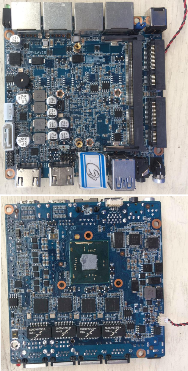
2.4 Onboard headers and Connectors
FCC WARNING
This device complies with part 15 of the FCC Rules. Operation is subject to the following two
conditions: (1) this device may not cause harmful interference, and (2) this device must accept
any interference received, including interference that may cause undesired operation.
Any changes or modifications not expressly approved by the party responsible for compliance
could void the user's authority to operate the equipment.
NOTE: This equipment has been tested and found to comply with the limits for a Class B
digital device, pursuant to Part 15 of the FCC Rules. These limits are designed to provide
reasonable protection against harmful interference in a residential installation. This equipment
generates, uses and can radiate radio frequency energy and, if not installed and used in
accordance with the instructions, may cause harmful interference to radio communications.
However, there is no guarantee that interference will not occur in a particular installation.
If this equipment does cause harmful interference to radio or television reception,
which can be determined by turning the equipment off and on, the user is encouraged to try to
correct the interference by one or more of the following measures:
-- Reorient or relocate the receiving antenna.
-- Increase the separation between the equipment and receiver.
-- Connect the equipment into an outlet on a circuit different
from that to which the receiver is connected.
-- Consult the dealer or an experienced radio/TV technician for help.
To maintain compliance with FCC’s RF Exposure guidelines, This equipment should be
installed and operated with minimum 20cm distance between the radiator and your body: Use
only the supplied antenna.