Proton SLRMINI3060 Speed and Length Gauge User Manual
Proton Products International Ltd. Speed and Length Gauge Users Manual
Proton >
Users Manual
Page 2 of 126
Proton Products SL mini and SLR mini Series Speed and Length Gauges Instruction Manual - issue 1s
Table of Contents
DECLARATION OF CONFORMITY (CE) .......................................................... 5
DECLARATION OF CONFORMITY (CSA) ....................................................... 6
LASER SAFETY PARAMETERS ...................................................................... 7
INTRODUCTION .......................................................................................... 8
PRINCIPLE OF OPERATION.......................................................................... 8
SPECIFICATIONS........................................................................................ 9
MODEL-SPECIFIC SPECIFICATIONS ......................................................................................................... 9
COMMON SPECIFICATIONS ..................................................................................................................... 9
DIMENSIONAL DRAWINGS ......................................................................... 11
ANNOTATED DRAWINGS ........................................................................... 12
TOP VIEW ........................................................................................................................................... 12
FRONT VIEW ....................................................................................................................................... 12
REAR VIEW ......................................................................................................................................... 13
UNDERSIDE VIEW ................................................................................................................................ 13
LED INDICATORS ................................................................................................................................ 14
ON-GAUGE LCD DISPLAY ........................................................................ 14
OPTIONAL ACCESSORIES ......................................................................... 15
DISPLAY ............................................................................................................................................. 15
POWER ............................................................................................................................................... 17
COMMUNICATIONS............................................................................................................................... 18
STANDS AND GUARDS ......................................................................................................................... 18
PROTECTION ....................................................................................................................................... 19
COOLING ............................................................................................................................................ 20
INSTALLATION ......................................................................................... 21
PRECAUTIONS ..................................................................................................................................... 21
Operating and storage temperature ........................................................................................................... 21
Protect from impact .................................................................................................................................... 21
Do not open or disassemble ........................................................................................................................ 21
Periodic maintenance .................................................................................................................................. 22
Laser radiation hazard ................................................................................................................................ 22
Optical windows .......................................................................................................................................... 23
OPTICAL WINDOW CLEANING PROCEDURE ............................................................................................. 24
INSTALLATION SEQUENCE .................................................................................................................... 24
MECHANICAL INSTALLATION ................................................................................................................. 25
Stand-off distance and depth-of-field ......................................................................................................... 25
Object stabilisation ..................................................................................................................................... 26
Optical alignment ........................................................................................................................................ 27
MEASUREMENT DIRECTION ...................................................................... 29
SL MINI UNIDIRECTIONAL SPEED AND LENGTH GAUGE .......................................................................... 29
SLR MINI BIDIRECTIONAL SPEED AND LENGTH GAUGE .......................................................................... 30
Mechanical mounting ................................................................................................................................. 30
ELECTRICAL INSTALLATION .................................................................................................................. 31
Earth connection ......................................................................................................................................... 31
Shielded Cables ........................................................................................................................................... 31
LASER ENABLE ................................................................................................................................... 32
SHUTTER CONTROL SWITCH, SHUTTER ENABLE INPUT AND SHUTTER STATE OUTPUT ........................... 33
SHUT_EN input electrical specifications ...................................................................................................... 33
Page 3 of 126
Proton Products SL mini and SLR mini Series Speed and Length Gauges Instruction Manual - issue 1s
SHUT_ST output electrical specifications .................................................................................................... 34
POWER SUPPLY .................................................................................................................................. 36
Powering on the gauge ............................................................................................................................... 36
Powering off the gauge ............................................................................................................................... 36
CONFIGURATION ..................................................................................... 37
PCIS_SLMINI SOFTWARE PC SYSTEM REQUIREMENTS ......................................................................... 37
PCIS_SLMINI SOFTWARE INSTALLATION .............................................................................................. 37
CONNECTION AND SOFTWARE START UP ............................................................................................... 38
WIFI CONFIGURATION .......................................................................................................................... 41
PCIS_SLMINI MAIN PAGE ....................................................................... 45
TREND GRAPH .................................................................................................................................... 46
Context menu .............................................................................................................................................. 47
Settings........................................................................................................................................................ 48
MEASUREMENT CONFIGURATION .............................................................. 51
Normal Operation Mode ............................................................................................................................. 54
Batch Operation Mode ................................................................................................................................ 54
Object Detection Mode ............................................................................................................................... 55
STANDARD COMMUNICATIONS INTERFACES ............................................... 57
CAN-BUS COMMUNICATIONS ............................................................................................................... 57
CAN-bus interface ....................................................................................................................................... 57
CAN-bus LED indicator ................................................................................................................................ 57
CAN-bus configuration ................................................................................................................................ 58
RS-232 COMMUNICATIONS ................................................................................................................. 60
RS-232 interface .......................................................................................................................................... 60
RS-232 Communications configuration ....................................................................................................... 61
RS-232 Printing ............................................................................................................................................ 62
Proton standard RS232 parameter access protocol .................................................................................... 65
Modbus parameter access protocol ............................................................................................................ 67
ETHERNET COMMUNICATIONS .............................................................................................................. 71
Ethernet interface ....................................................................................................................................... 71
Ethernet LED indicator ................................................................................................................................ 71
Ethernet configuration ................................................................................................................................ 72
Input Parameter Write Disable ................................................................................................................... 74
UDP Protocol ............................................................................................................................................... 76
OPTIONAL COMMUNICATIONS INTERFACES ................................................ 78
PROFIBUS COMMUNICATIONS ............................................................................................................ 78
PROFIBUS interface ..................................................................................................................................... 78
PROFIBUS LED indicator .............................................................................................................................. 78
PROFIBUS configuration .............................................................................................................................. 79
ETHERNET / IP OR PROFINET COMMUNICATIONS ............................................................................... 80
EtherNet / IP or PROFINET interface ........................................................................................................... 80
EtherNet / IP or PROFINET LED indicator .................................................................................................... 81
EtherNet / IP or PROFINET configuration .................................................................................................... 81
DEVICENET COMMUNICATIONS ............................................................................................................. 83
DeviceNet interface ..................................................................................................................................... 83
DeviceNet LED indicator .............................................................................................................................. 83
DeviceNet configuration.............................................................................................................................. 84
STANDARD ELECTRICAL INTERFACES ........................................................ 86
LOGIC INPUTS ..................................................................................................................................... 86
Logic inputs connection ............................................................................................................................... 86
Logic inputs configuration ........................................................................................................................... 87
LOGIC OUTPUTS ................................................................................................................................. 91
Logic outputs connection ............................................................................................................................ 91
Page 4 of 126
Proton Products SL mini and SLR mini Series Speed and Length Gauges Instruction Manual - issue 1s
Logic outputs electrical specifications ......................................................................................................... 91
Logic outputs configuration ........................................................................................................................ 92
PULSE OUTPUTS ................................................................................................................................. 95
Pulse outputs connection ............................................................................................................................ 95
Pulse outputs electrical specifications ......................................................................................................... 96
DATA LOGGING ..................................................................................... 103
CONNECTOR PIN OUTS ........................................................................... 105
OPTIONAL PSU-BOB MINI ..................................................................... 106
CAN ................................................................................................................................................ 106
RS232 ............................................................................................................................................. 106
I-BUS ............................................................................................................................................... 107
RJ45 SOCKET .................................................................................................................................. 107
SCREW TERMINALS ........................................................................................................................... 108
KEY SWITCH ...................................................................................................................................... 109
DIMENSIONAL DRAWING ..................................................................................................................... 110
INPUT PARAMETERS ............................................................................... 111
OUTPUT PARAMETERS ........................................................................... 114
APPENDIX 1: HIGH ACCURACY LENGTH MEASUREMENT OF DISCRETE OBJECTS
APPLICATION NOTE ................................................................................ 116
PROBLEM ......................................................................................................................................... 116
SOLUTION ......................................................................................................................................... 116
IMPLEMENTATION .............................................................................................................................. 117
Connections to the SL / SLR / SL mini / SLR mini gauge ............................................................................. 118
Logic input electrical characteristics ......................................................................................................... 119
Gauge software configuration .................................................................................................................. 119
EXAMPLE IMPLEMENTATION USING BANNER QS18 LASER EMITTERS AND QS186LE NPN SENSORS ..... 121
SL mini / SLR mini configuration ................................................................................................................ 122
CONTACT DETAILS FOR ENQUIRIES, SALES AND SERVICE ........................... 126
WEB SITE .......................................................................................................................................... 126
ENQUIRIES AND SALES ....................................................................................................................... 126
SERVICE ENQUIRIES .......................................................................................................................... 126
MANUAL FEEDBACK AND COPYRIGHT ...................................................... 126
Page 5 of 126
Proton Products SL mini and SLR mini Series Speed and Length Gauges Instruction Manual - issue 1s
DECLARATION OF CONFORMITY (CE)
This is to certify that the following equipment conforms to the requirements of
CE including EMC to the heavy industrial standard Class A.
Equipment Covered
Product name
Description
Part number
SL mini 1220
Unidirectional non-contact speed and length gauge (stand-off
distance: 120mm, depth-of field: 20mm)
00050MC001
SL mini 3060
Unidirectional non-contact speed and length gauge (stand-off
distance: 300mm, depth-of field: 60mm)
00050MC002
SLR mini 1220
Bidirectional non-contact speed and length gauge (stand-off
distance: 120mm, depth-of field: 20mm)
00050MC011
SLR mini 3060
Bidirectional non-contact speed and length gauge (stand-off
distance: 300mm, depth-of field: 60mm)
00050MC012
The manufacturer of the above named equipment is:
Proton
Proton Products is an ISO9001:2008 registered company.
The declaration is signed by:
Paul Alexander Sives ………………………
Page 6 of 126
Proton Products SL mini and SLR mini Series Speed and Length Gauges Instruction Manual - issue 1s
DECLARATION OF CONFORMITY (CSA)
This is to certify that the following equipment has been manufactured in
compliance with the standards for Machine Safety and Workplace Electrical
Safety according to the CSA (Canadian Standards Association).
Equipment Covered
Product name
Description
Part number
SL mini 1220
Unidirectional non-contact speed and length gauge (stand-off
distance: 120mm, depth-of field: 20mm)
00050MC001
SL mini 3060
Unidirectional non-contact speed and length gauge (stand-off
distance: 300mm, depth-of field: 60mm)
00050MC002
SLR mini 1220
Bidirectional non-contact speed and length gauge (stand-off
distance: 120mm, depth-of field: 20mm)
00050MC011
SLR mini 3060
Bidirectional non-contact speed and length gauge (stand-off
distance: 300mm, depth-of field: 60mm)
00050MC012
The manufacturer of the above named equipment is:
Proton
Proton Products is an ISO9001:2008 registered company.
The declaration is signed by:
Paul Alexander Sives ………………………
Page 7 of 126
Proton Products SL mini and SLR mini Series Speed and Length Gauges Instruction Manual - issue 1s
LASER S AFETY P ARAMETERS
www.protonproducts.com
Proton Products SL mini and SLR mini series laser speed and length gauges emit laser radiation with
the following parameters:
Parameter
Model
Minimum
Typical
Maximum
Units
Wavelength
All
650
658
670
nm
Beam diameter
All
3
mm
Spot size at standoff distance
All
3
mm
Beam divergence
All
1.5
mrad
Total emitted power
SL mini
40
mW
SLR mini
80
mW
Emitted power per beam
(2 beams are emitted)
SL mini
20
mW
SLR mini
40
mW
Power density at gauge window
(normal operation)
SL mini
280
mW/cm2
SLR mini
560
mW/cm2
Power density at gauge window
(absolute maximum)
SL mini
560
mW/cm2
SLR mini
1120
mW/cm2
Power density at standoff distance
SL mini
560
mW/cm2
SLR mini
1120
mW/cm2
Nominal hazard zone (NHZ) distance
(diffuse surface reflection)*
All
20 to 100
mm
Nominal hazard zone (NHZ) distance
(specular / reflective surface reflection)
All
150
m
*this distance is highly dependent on the nature and type of diffuse surface.
For further inform ation, please contact your Proton Products representative or Proton Products
M anufacturer signature:
Paul Alexander Sives: ………………………
Proton Products is an ISO9001:2008 registered company.
Page 8 of 126
Proton Products SL mini and SLR mini Series Speed and Length Gauges Instruction Manual - issue 1s
INTRODUCTION
The Proton Products SL mini and SLR mini series of laser speed and length gauges provide highly-
accurate, non-contact speed and length measurement.
SL mini series gauges offer speed and length measurement for unidirectional production lines.
SLR mini series gauges offer speed and length measurement for bidirectional production lines. The
gauge senses the direction of motion and will automatically increment or decrement the length
accordingly. SLR mini gauges are thus suitable for production lines that undergo direction reversals or
stationary (zero speed) periods.
Compared to traditional contact wheel encoders, SL mini / SLR mini non-contact speed and length
gauges offer the following advantages:
Capable of measurement at much higher speeds and accelerations
No slippage
Greater accuracy
No wear or damage to the measured object
Solid state design results in higher reliability and MTBF
RS-232 and Ethernet communication interfaces are installed as standard for straightforward
connection to computers or PLCs. One optional industrial standard communication interface
(PROFIBUS, EtherNet/IP or DeviceNET; replaces the standard Ethernet interface) may also be
installed in the gauge.
User configurable digital inputs are provided as standard to reset gauge measurements and trigger
printing. User configurable digital outputs are provided as standard to signal gauge status and preset
length reached.
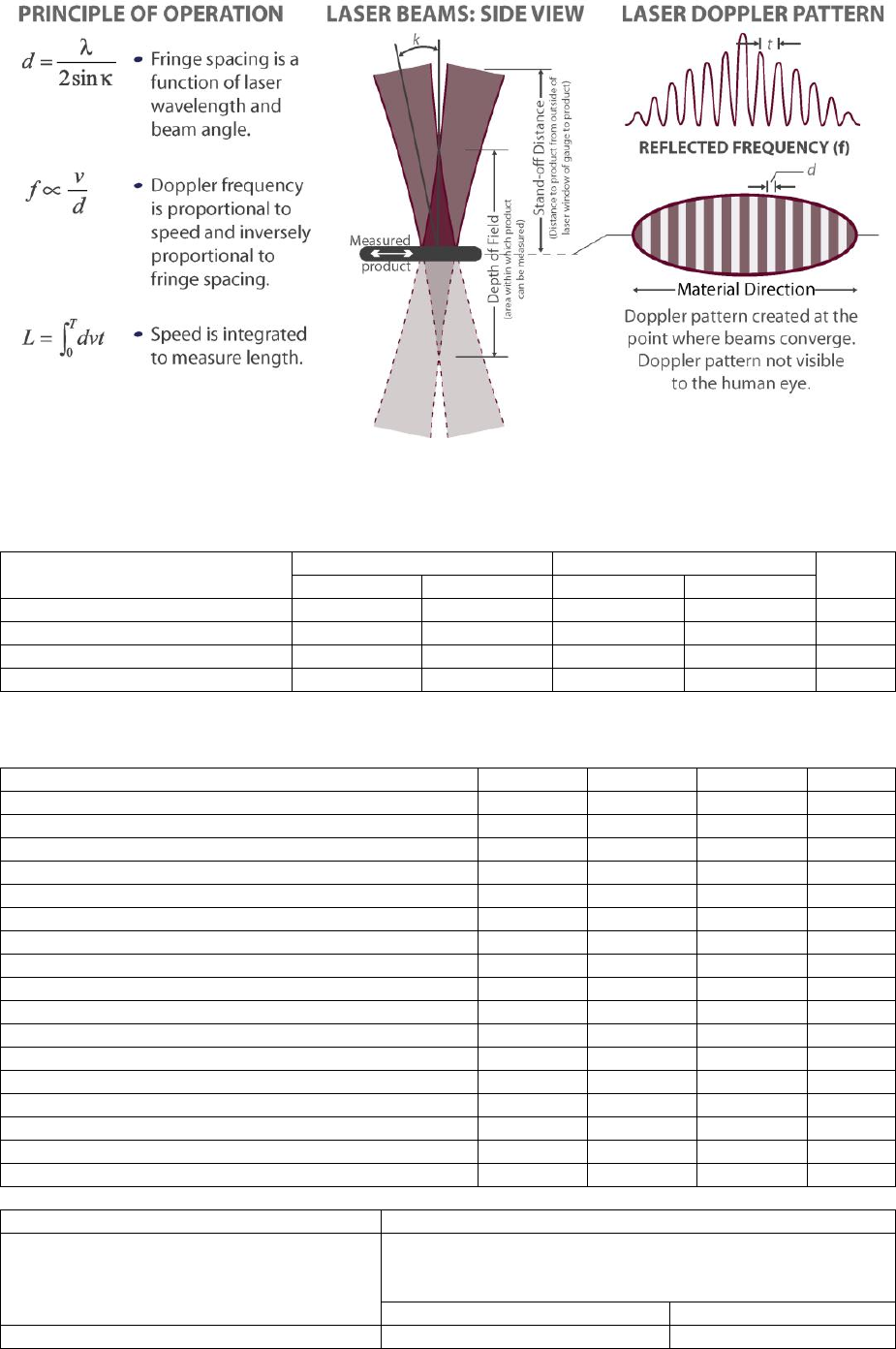
PRINCIPLE OF OPERATION
SL mini series unidirectional speed and length gauges illuminate the measured surface with a
precisely pitched interference pattern created by the intersection of two laser beams. The alternating
bright and dark interference fringes modulate the light scattered by the object with a frequency
proportional to the object speed. This scattered light is detected by a photodiode and the electrical
signal digitally processed to determine the frequency and hence the speed. Object length is then
calculated by integrating the speed measurement over time.
SLR mini series bidirectional speed and length gauges extend this principle by using a high-frequency
Bragg cell modulator to illuminate the measured surface with a scanning interference pattern, which
generates an oscillating light signal even when the object is stationary. Direction of motion is
determined by whether the scattered light frequency is higher or lower than the stationary frequency.
Page 9 of 126
Proton Products SL mini and SLR mini Series Speed and Length Gauges Instruction Manual - issue 1s
SPECIFICATIONS
MODEL-SPECIFIC SPECIFICATIONS
Specification
Unidirectional – SL mini
Bidirectional – SLR mini
Units
1220
3060
1220
3060
Minimum speed
0.1
0.25
0
0
m/min
Maximum speed
2000
5000
±2000
±5000
m/min
Nominal stand-off distance
120
300
120
300
mm
Depth of field
20
60
20
60
mm
COMMON SPECIFICATIONS
Specification
Minimum
Typical
Maximum
Units
Accuracy
-0.05
0.05
%
Repeatability
-0.02
0.02
%
Acceleration
1000
m/s2
Measurement update time
20
µs
Laser beam diameter
3
mm
Laser classification
3B
-
Operating temperature
+5
+40
°C
Environmental protection
IP67
-
Power supply voltage
15
24
28
VDC
Power consumption
15
W
Length
140
mm
Width
105
mm
Height
50
mm
Measurement display
Integrated backlit LCD
Pulse outputs
2× RS-422 compliant differential pair outputs with
maximum pulse rate < 2 MHz (cable length dependent),
end-user configurable as:
2× independent pulse outputs
1× quadrature output
Laser safety
Laser enable input
Open shutter input

Page 10 of 126
Proton Products SL mini and SLR mini Series Speed and Length Gauges Instruction Manual - issue 1s
Shutter status output
3× Logic inputs (end-user configurable
functions)
Reverse Direction
Length Hold
Reset
Speed Hold
End of Reel
Display Hold
2× Logic outputs (end-user configurable
functions)
Gauge OK
Gauge too hot
Good reading
Object detected
Preset length 1 / Batch length reached
Preset length 2 / Batch number reached
Gauge measuring speed
Standard communications interfaces
RS-232*
CANbus**
Ethernet TCP/IP (Modbus protocol)
Optional communications interface (select
one; replaces the Ethernet interface)
PROFIBUS
PROFINET
DeviceNet
EtherNet/IP
*An optional RS-232-to-USB converter cable is available for connection to USB equipped computers.
**CAN-bus protocol is proprietary and reserved for connection to other Proton Products equipment
such as a CDI interface display unit.
Page 11 of 126
Proton Products SL mini and SLR mini Series Speed and Length Gauges Instruction Manual - issue 1s
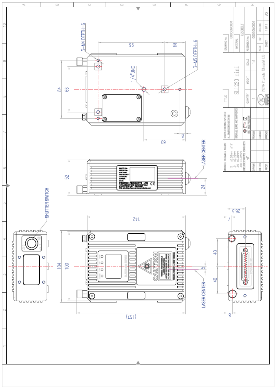
DIMENSIONAL DRAWINGS
Page 12 of 126
Proton Products SL mini and SLR mini Series Speed and Length Gauges Instruction Manual - issue 1s
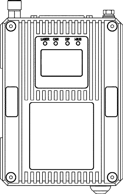
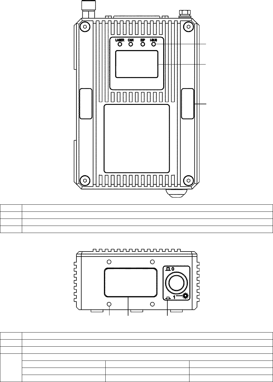
ANNOTATED DRAWINGS
TOP VIEW
Label
Description
1
LED indicators
2
LCD display
3
Tamper-evident seal (×2; damage to or removal will invalidate the product warranty)
FRONT VIEW
Label
Description
1
Optional air wipe / beam enclosure tube mounting holes (×4)
2
Optical window
3
Laser shutter control switch
Switch status
Laser shutter status
Laser beam status
Out
Closed
Blocked
In
Open
Emitting
1
2
3
1
2
3
Page 13 of 126
Proton Products SL mini and SLR mini Series Speed and Length Gauges Instruction Manual - issue 1s
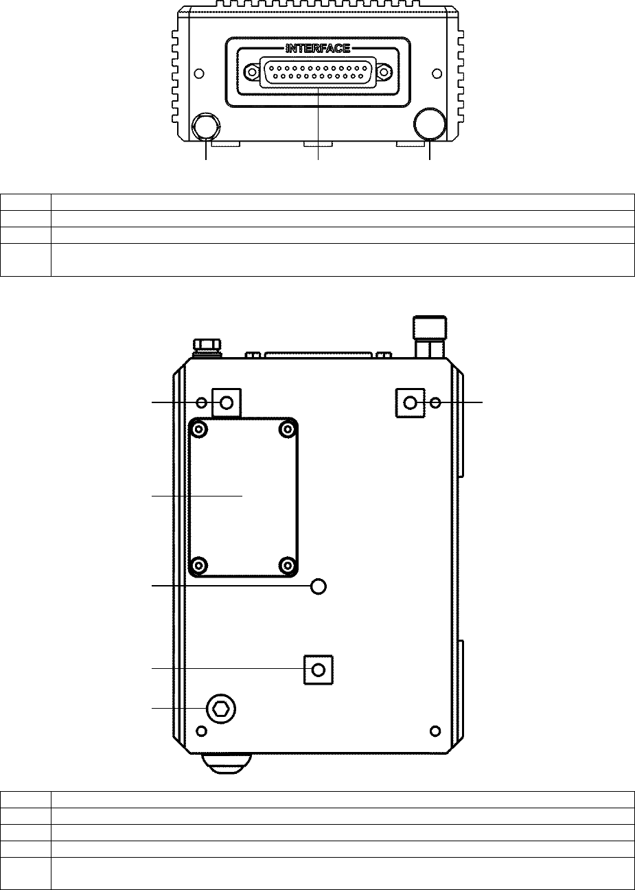
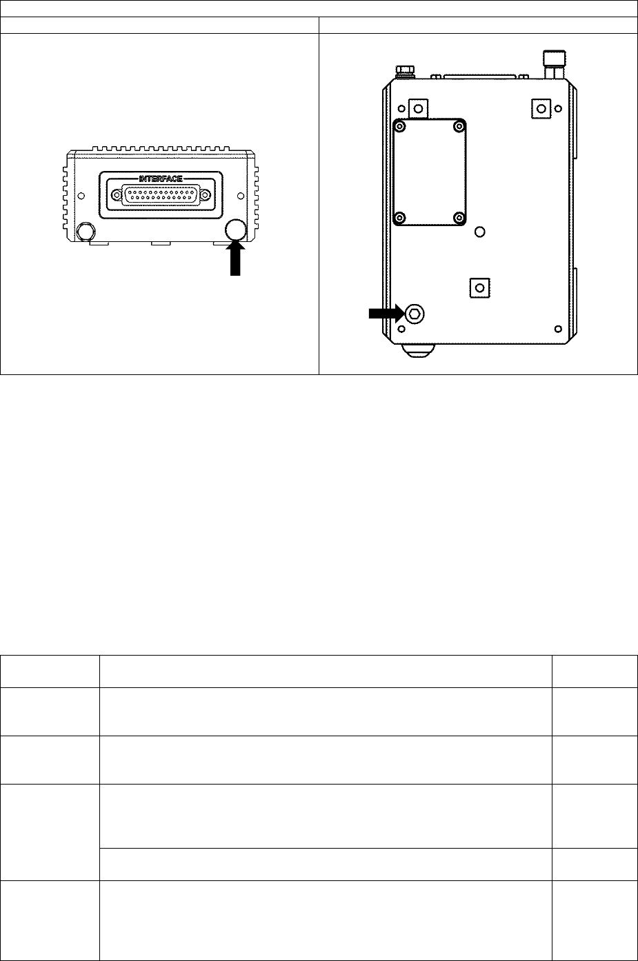
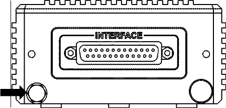
REAR VIEW
Label
Description
1
Earthing bolt
2
“INTERFACE” connector port
3
Nitrogen gas purge port (for factory use only; any attempt to open or connect to this port will
invalidate the product warranty)
UNDERSIDE VIEW
Label
Description
1
M5 threaded mounting hole (×3)
2
¼”-20 UNC threaded tripod mounting hole
3
Communications module compartment cover
4
Nitrogen gas purge port (for factory use only; any attempt to open or connect to this port will
invalidate the product warranty)
1
2
3
3
1
1
2
1
4
Page 14 of 126
Proton Products SL mini and SLR mini Series Speed and Length Gauges Instruction Manual - issue 1s
LED INDICATORS
Label
Condition
Description
LASER
Extinguished
No laser emission
Yellow
Laser emission
CAN
Extinguished
No CANbus connection
Green
CANbus connected
EIP
Extinguished
No Ethernet connection
Green
Ethernet connected
Flashing red
Ethernet data transmission
i-BUS
Extinguished
Optional DeviceNET / PROFIBUS / PROFINET / EtherNet/IP not connected
Green
Optional DeviceNET / PROFIBUS / PROFINET / EtherNet/IP connected
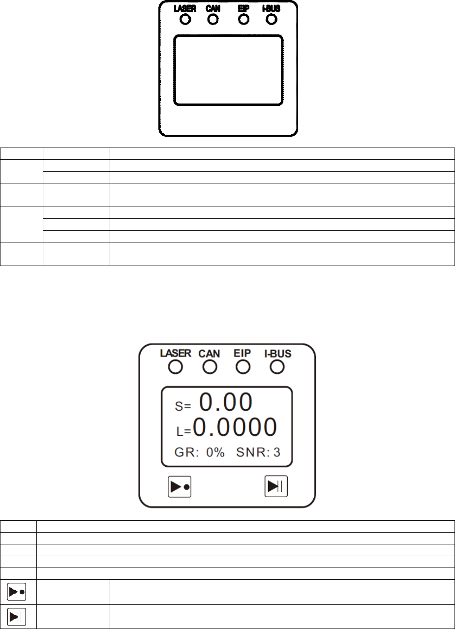
ON-GAUGE LCD DISPLAY
The SL mini and SLR mini gauges are fitted with a backlit, on-gauge LCD which displays the following
information:
Label
Description
S
Measured speed
L
Measured length
GR
Good Readings percentage
SNR
Signal-to-Noise Ratio
Reset button
Press to reset the length to zero.
Pause button
Press to pause the speed measurement.
Page 15 of 126
Proton Products SL mini and SLR mini Series Speed and Length Gauges Instruction Manual - issue 1s
OPTIONAL ACCESSORIES
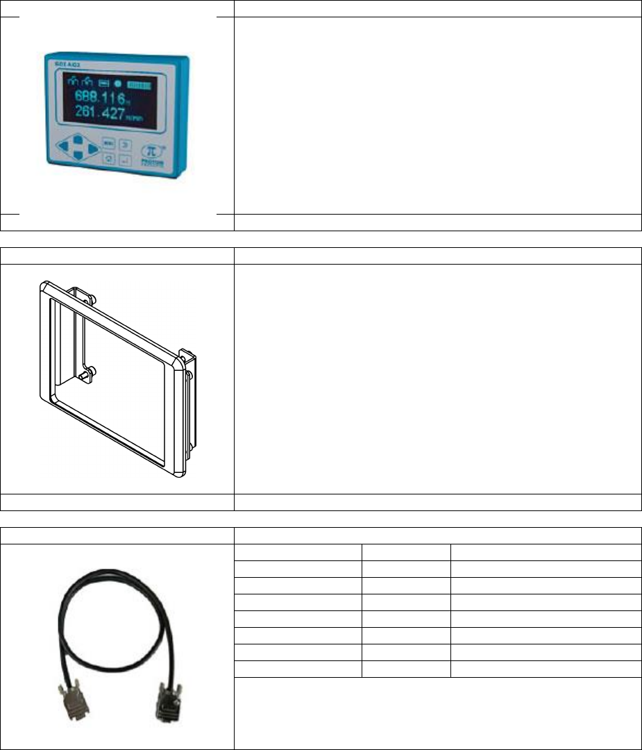
DISPLAY
AiG2-SL/SLR
Display module
Connects via the CAN-bus port.
Displays measured speed and length.
Provides menu-based setting of all parameters.
Bright VFD dot matrix display.
Proton part number
00041MC045
AiG2 Panel Mount Kit
Bracket for mounting the AiG2 to an end-user panel.
Proton part number
00041MC049
CAN-bus cable
Name
Length / m
Proton part number
CAN 9DD_001M
1
00041CB001
CAN 9DD_005M
5
00041CB005
CAN 9DD_010M
10
00041CB010
CAN 9DD_020M
20
00041CB020
CAN 9DD_040M
40
00041CB040
CAN 9DD_060M
60
00041CB060
CAN 9DD_100M
100
00041CB100
Page 16 of 126
Proton Products SL mini and SLR mini Series Speed and Length Gauges Instruction Manual - issue 1s
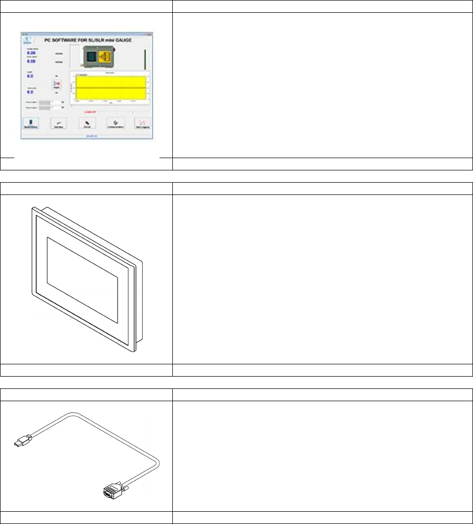
PCiS_SL/SLR mini
PC Interface Software
PC-based software package.
User-friendly graphical user interface.
Displays all measurements.
Provides menu-based setting of all parameters.
Provides trending, data logging, presets and alarms.
Gauge to PC connection via RS-232.
Proton part number
00050SW001
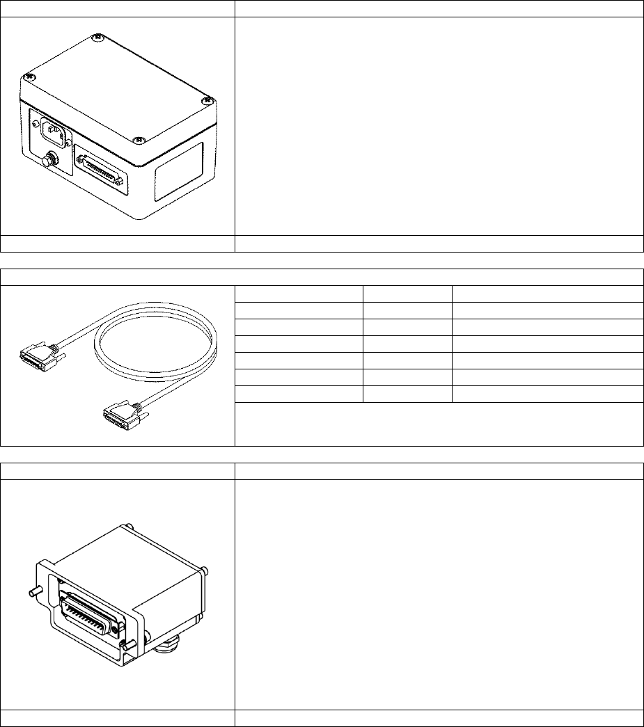
7”Touch Screen PC
Industrial PC
For running the above PCiS_SL/SLR mini software
User-friendly graphical user interface.
Displays all measurements.
Provides menu-based setting of all parameters.
Provides trending, data logging, presets and alarms.
Gauge to PC connection via RS-232 or optional RS-
232-to-USB interface cable (RSCon).
Proton part number
00043MC029
USB-RS232 Cable
For connecting the RS232 port of the PSU-BOB mini to
the 7″ Touch Screen PC.
Length: 1.8m.
Proton part number
GP00000624
Page 17 of 126
Proton Products SL mini and SLR mini Series Speed and Length Gauges Instruction Manual - issue 1s
POWER
PSU-BOB mini
Power supply and mini break out box
Connects via the DB25 “INTERFACE” connector.
Supplies 24VDC electrical power to the gauge.
Provides screw terminal access to all electrical
interfaces.
Provides DB9 connectors for access to the CANbus,
RS232 and industrial bus communications interfaces.
Provides a RJ45 socket for the Ethernet interface.
End user cables are sealed with three cable glands.
Input voltage range: 90 – 260 VAC @ 45 – 65 Hz.
Select the required length of DB25 cable from below.
Proton part number
00050MC039
DB25 “INTERFACE” port to PSU-BOB mini cable
Name
Length / m
Proton part number
BOB 25DD_001M
1
00041CT001
BOB 25DD_003M
3
00041CT003
BOB 25DD_005M
5
00041CT005
BOB 25DD_010M
10
00041CT010
BOB 25DD_020M
20
00041CT020
BOB 25DD_030M
30
00041CT030
Terminal Expander
Gauge-mounted break-out box
Connects via the DB25 “INTERFACE” connector.
Provides DB9 connector access to the RS-232, CAN-
bus, Ethernet or optional industrial bus communications
ports.
Provides screw terminal access to all electrical input
and output pins.
End user cables are sealed with cable glands.
Proton part number
00050MC039
Page 18 of 126
Proton Products SL mini and SLR mini Series Speed and Length Gauges Instruction Manual - issue 1s
COMMUNICATIONS
Industrial Bus Module
For connecting the gauge to industrial communications
buses, such as used with PLCs.
May be field retrofitted.
Protocol
Proton part number
DeviceNET
00043MC006
PROFIBUS
00043MC022
PROFINET
00043MC031
EtherNet/IP
00043MC005
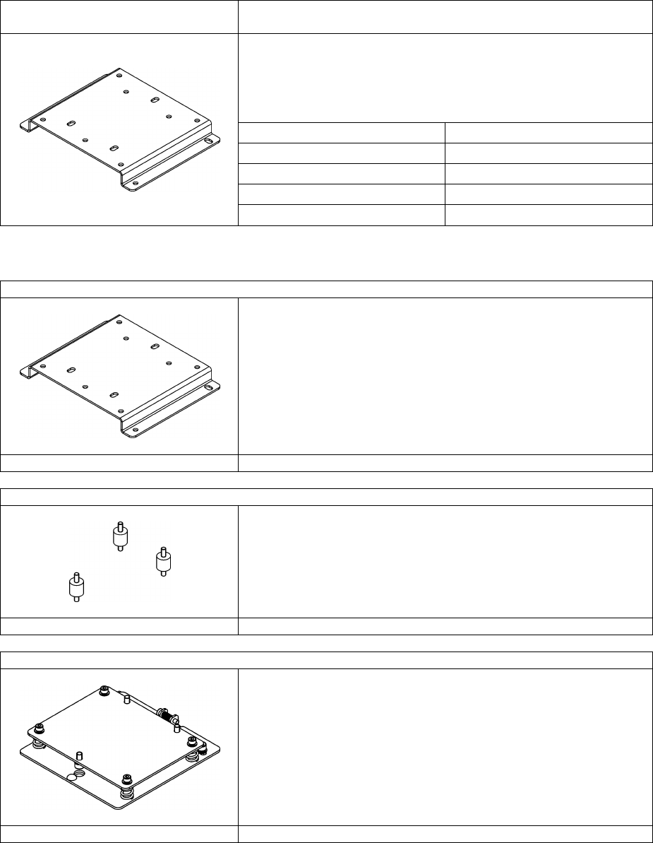
STANDS AND GUARDS
Base Plate
For securing a SL/SLR mini gauge to a mounting
surface.
Proton part number
00050MC042
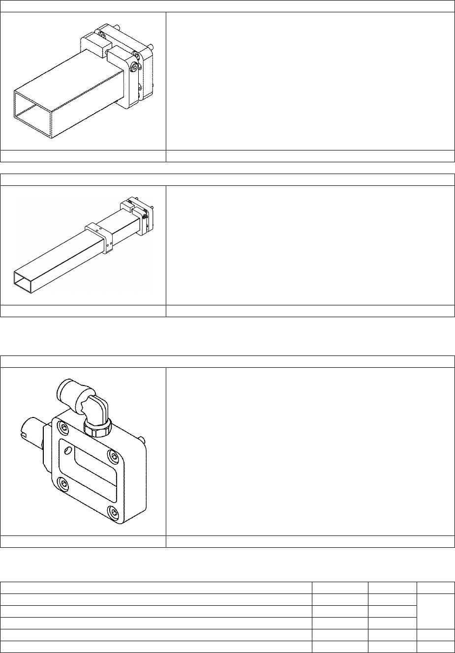
Vibration reducing kit
For use with the above Base Plate (00050MC042) in
high-vibration environments.
Proton part number
00050MC043
3D Adjuster Plate
For use with the above Base Plate (00050MC042) for
precision alignment of the SL/SLR mini gauge to the
measured object.
Provides ±3° of roll and yaw adjustment.
Proton part number
00050MC044
Page 19 of 126
Proton Products SL mini and SLR mini Series Speed and Length Gauges Instruction Manual - issue 1s
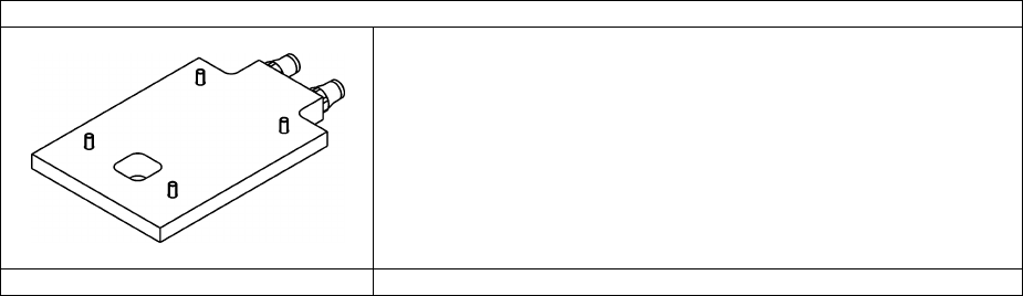
Laser Protection Tube for SL/SLR mini 1220
Enclosure of the laser beam to within 10mm of the
object for laser safety and harsh environments.
Proton part number
00050MC033
Laser Protection Tube for SL/SLR mini 3060
Enclosure of the laser beam to within 10mm of the
object for laser safety and harsh environments.
Proton part number
00050MC037
PROTECTION
Air wipe
High-efficiency, air-wiped protection window for
dusty/steamy environments with a quick-change
window release mechanism.
Provides an 8 mm push fit tube fitting to connection to a
clean air source.
Proton part number
00050MC034
Air quality must meet or exceed ISO 8573.1:2001 Class 1.3.1 (solids.water.oil):
Specification
Maximum
Units
Class
0.1 - 0.5 μm solid particle count
100
/ m3
1
0.5 - 1 μm solid particle count
1
/ m3
1 - 5 μm solid particle count
0
/ m3
Water vapour pressure dew point
-20
°C
3
Oil aerosol and vapour
0.01
mg / m3
1
Page 20 of 126
Proton Products SL mini and SLR mini Series Speed and Length Gauges Instruction Manual - issue 1s
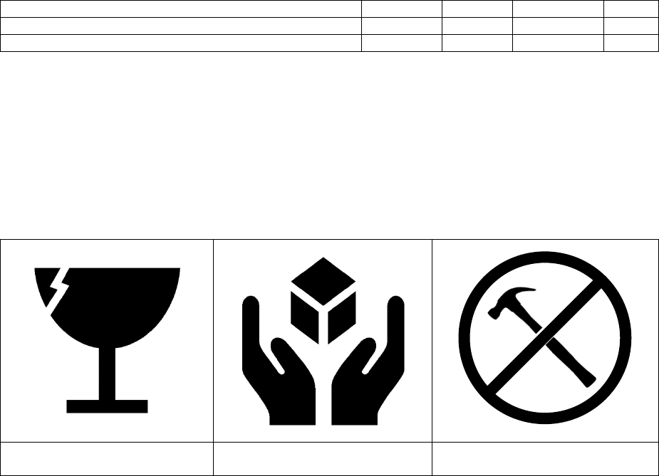
COOLING
Cooling Plate
Air or water cooled plate for installation between the
gauge and mounting surface.
For use in ambient temperatures up to 60°C.
Proton part number
00050MC031
Page 21 of 126
Proton Products SL mini and SLR mini Series Speed and Length Gauges Instruction Manual - issue 1s
INSTALLATION
PRECAUTIONS
Operating and storage temperature
Specification
Minimum
Typical
Maximum
Units
Operating temperature
+5
+45
°C
Storage temperature
0
+45
°C
Do not store or operate the gauge in temperatures outside of the specified ranges.
Do not install the gauge near high temperature surfaces or objects which may cause it to
overheat.
Storage or operation of the gauge outside the specified temperature range may result in
degraded measurement accuracy, malfunction or damage to the gauge.
All gauges are fitted with internal temperature sensors which will permanently log any over-
temperature condition that invalidates the warranty.
Protect from impact
Fragile
Do not drop
Protect from impact and
mechanical shock
The gauge contains delicate optical and electronic assemblies and must never be dropped or
struck by other objects.
Only install the gauge on its mounting/stand when all machining, assembly and transportation
of the mounting/stand has been completed.
Do NOT strike, move or perform machining operations on the mounting/stand with the gauge
installed.
Damage incurred by the gauge as a result of impact, mechanical shock or rough handling is
NOT covered by the manufacturer’s warranty.
Do not open or disassemble
The gauge contains no user serviceable components.
Loosening the gauge screws or removing its cover will invalidate the gauge warranty.
Damage to or removal of any of the anti-tamper stickers will invalidate the gauge warranty.
The gauge is factory-purged with dry nitrogen gas to prevent condensation on the internal
optics; opening of the gas purge ports (indicated below) will invalidate the gauge warranty.
Page 22 of 126
Proton Products SL mini and SLR mini Series Speed and Length Gauges Instruction Manual - issue 1s
WARNING: Do NOT attempt to open either of the gas purge ports indicated below:
Rear view
Underside view
Periodic maintenance
The physical condition of the gauge, optional accessories and connecting cables should be
checked periodically; if any damage is suspected, then the unit should be taken out of service
for inspection and repair or replacement of damaged parts.
Laser radiation hazard
This product emits class 3B laser radiation; do not view the laser beams emitted by the gauge
either directly or by specular reflection.
For all class 3B laser devices, the safety measures below MUST be provided. Some
measures are the responsibility of the device manufacturer (Proton Products), whilst other
measures are the responsibility of the end-user.
For further information on laser safety, please refer to European standard BS EN 60825-
1:2007 “Safety of laser products; Part 1: Equipment classification, requirements and user’s
guide”.
Safety
Measure
Description
Provided
by
Laser Safety
Officer
A Laser Safety Officer (LSO) must be appointed by the end-user
organisation and is responsible for ensuring that both the equipement
and staff comply with laser safety regulations.
End-user
Laser safety
training
The end-user organisation must provide appropriate laser safety
training for all operators and maintenance personnel working in close
proximity to the gauge.
End-user
Laser enable
key-switch
A key-switch to disable the laser diode should be wired to the LSR_EN
input. The laser safety officer should be responsible for the key and
must withhold it during system maintenance or it the system fails to
comply with laser safety regulations.
End-user
A laser enable key-switch is provided on the optional PSU-
BOB-mini.
Proton
Contain and
terminate
beam path
Terminate the laser beams at the end of their useful length (behind the
measured object) with a beam block.
Contain laser beam paths with laser guards which have closure
switches wired to the SHUT_EN input so that the laser shutter is closed
End-user
Page 23 of 126
Proton Products SL mini and SLR mini Series Speed and Length Gauges Instruction Manual - issue 1s
Safety
Measure
Description
Provided
by
if any guard is opened.
Do NOT permit the laser beams to be directed into open space.
Prevent
specular
(mirror-like)
reflections
Never direct the laser beams at specular (mirror-like) reflectors.
Remove all reflective objects such as jewellery or wristwatches before
working near the laser beams.
End-user
Emission
indicator
Illumination of the “LASER” LED on the gauge indicates laser emission.
Proton
An external laser emission warning light may be triggered by the
SHUT_ST output.
End-user
Laser shutter
switch
The switch to the side of the laser window opens or closes the laser
shutter which blocks laser emission.
Proton
If the gauge is to be mounted in an inaccessible location, then this
switch should be set to the open position and a remote, external laser
shutter switch wired to the SHUT_EN input.
End-user
Laser
protection
eyewear
Laser protection eyewear rated with the Optical Density (OD) rated for
Class 3B lasers must be worn whenever there is a risk of eye exposure
to the laser, for example during gauge alignment (see the “Laser Safety
Parameters” section for information on laser wavelength, power and
power densities).
End-user
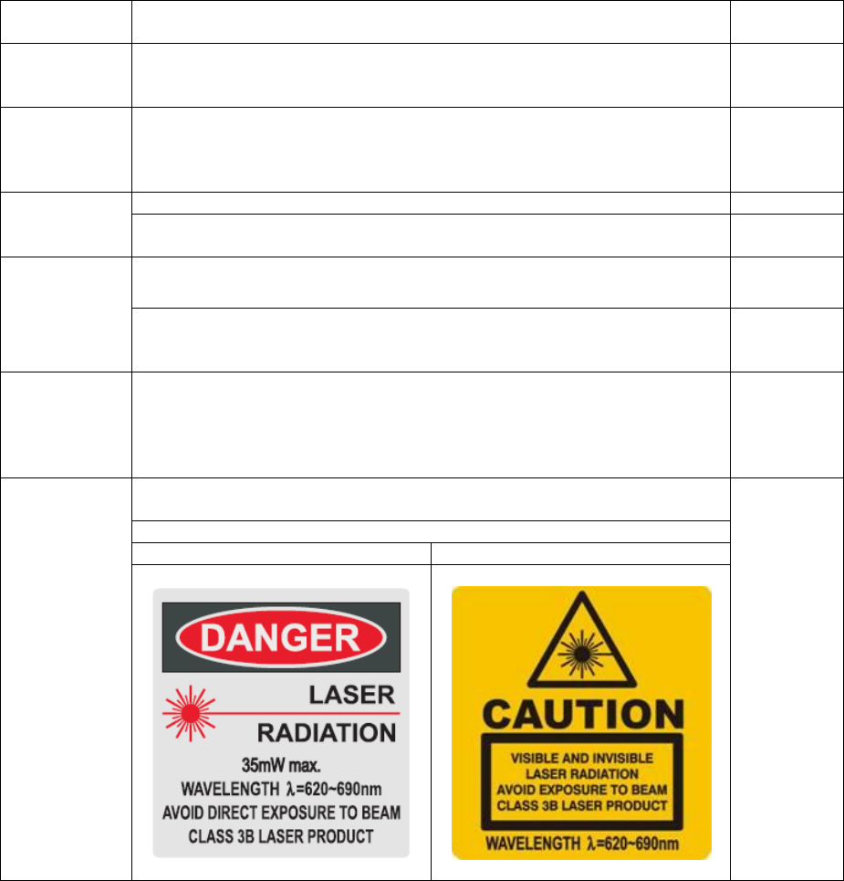
Laser
warning signs
Class 3B laser warning signs must displayed in the working area;
precautions on the warning signs must be followed.
End-user
Example class 3B laser warning signage:
US standard
European standard
Optical windows
Do not allow smoke, water, steam, dust or other debris to come into contact with any of the
optical window.
Obstruction of the optical window may degrade measurement accuracy or inhibit
measurement.
If the optical window appears to be damaged or misaligned, then the unit should be sent to a
Proton Products authorised service agent for repair.
If the optical window requires cleaning, then refer to the cleaning procedure detailed below to
minimise the risk of scratching the windows.

Page 24 of 126
Proton Products SL mini and SLR mini Series Speed and Length Gauges Instruction Manual - issue 1s
OPTICAL WINDOW CLEANING PROCEDURE
The optical window is manufactured from anti-reflection coated optical glass; it must be
treated with the same level of care as a high-performance camera lens.
Before inspecting or cleaning the optical window, ensure that the gauge is powered
off, the LSR_EN key-switch is locked out and no laser light is emitted.
Required items
Notes
Small blower brush
Such as the type used to remove dust from camera lenses.
Lens cleaning tissues or
micro-fibre lens cleaning cloth
Do NOT use facial tissues as these can scratch delicate optics.
Lens cleaning solution
Such as the type specified for cleaning camera lenses.
1. Use the small blower brush to remove any visible dust on the optical window.
2. Apply a few drops of lens cleaning solution to a fresh lens cleaning tissue or a clean micro-
fibre lens cleaning cloth.
3. Gently wipe the optical window from the centre outwards; apply only light pressure to the
tissue or cloth when wiping the optical window.
4. Repeat as necessary with fresh tissues or a clean section of cloth until the optical window is
clean and free of all smears and smudges.
INSTALLATION SEQUENCE
Unpack the gauge and check for missing accessories and shipping damage.
Mechanical installation:
1. Mount the gauge securely either on a user supplied mount or on an optional Proton Products
mounting plate.
Electrical installation:
1. Install earth connections.
2. Connect the gauge to an optional Proton Products PSU-BOB mini power supply and break-
out box.
3. Install laser safety connections (laser enable, shutter enable and shutter status).
4. Install communications interface connections (RS-232, Ethernet or optional PROFIBUS,
PROFINET, EtherNet/IP or DeviceNET).
5. Install electrical interface connections (logic inputs, logic outputs, pulse outputs) using the
optional Proton Products PSU-BOB mini breakout box or terminal strip.
6. Connect a PC installed with the PCiS_SLmini software to the gauge via the RS-232, Ethernet
or optional PROFINET or EtherNet/IP communications interface.
7. Configure the gauge using the PCiS_SLmini software.
Page 25 of 126
Proton Products SL mini and SLR mini Series Speed and Length Gauges Instruction Manual - issue 1s
MECHANICAL INSTALLATION
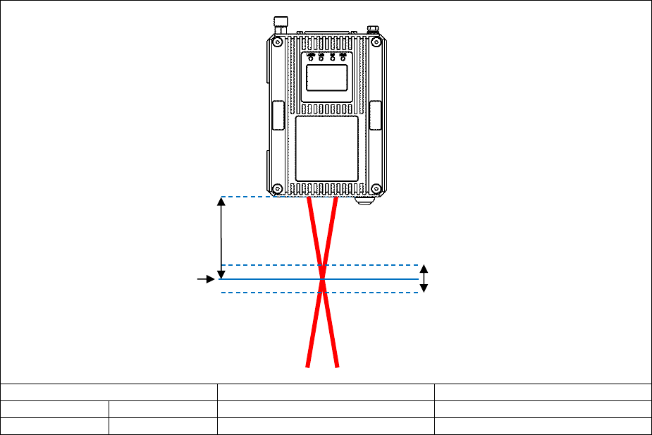
Stand-off distance and depth-of-field
For best accuracy, locate the measured object at the specified stand-off distance to the
gauge.
Speed and length measurement is possible for objects located away from the specified stand-
off distance but still within the depth-of-field; however the measurement accuracy may be
degraded by the reduced signal strength.
Model
Stand-off distance / mm
Depth-of-field / mm
SL mini 1220
SLR mini 1220
120
20
SL mini 3060
SLR mini 3060
300
60
Stand-off distance
Depth-of-field
Ideal object location
Page 26 of 126
Proton Products SL mini and SLR mini Series Speed and Length Gauges Instruction Manual - issue 1s
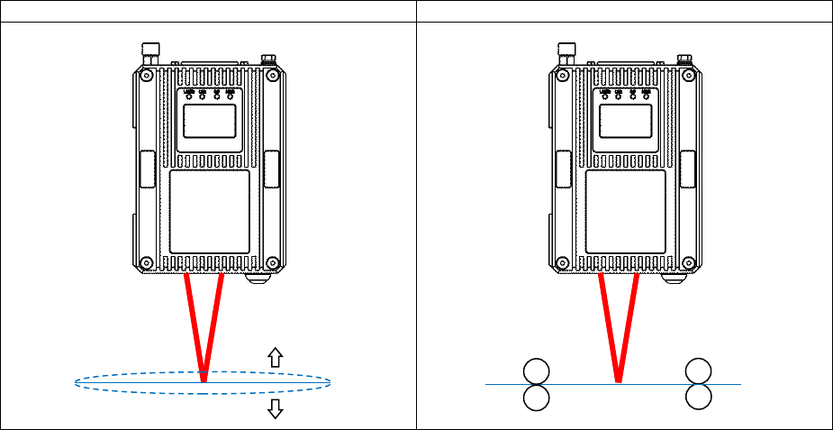
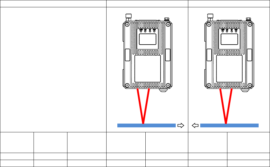
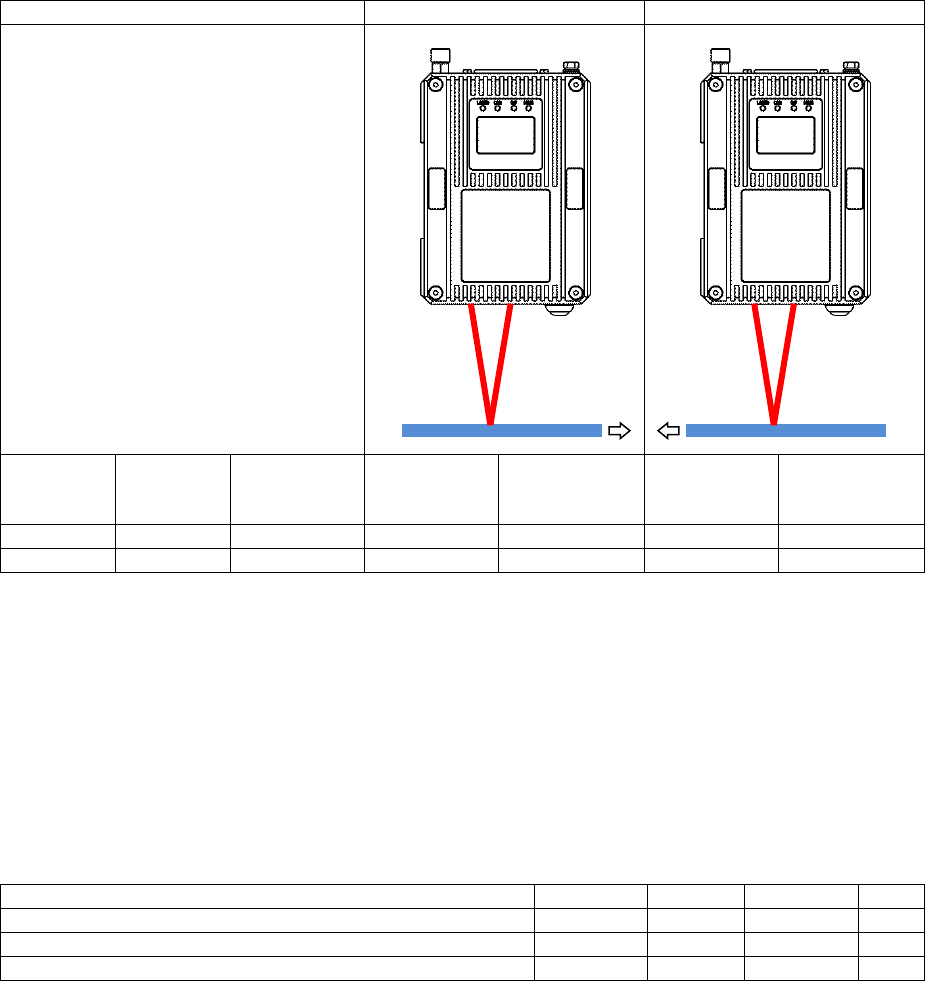
Object stabilisation
For accurate speed and length measurements, the distance between the measured object and the
gauge must be kept constant; the measured object must be guided to prevent flutter:
Incorrect
Correct
The end-user must provide suitable mechanisms for guiding and stabilising the motion of the
measured object.
Page 27 of 126
Proton Products SL mini and SLR mini Series Speed and Length Gauges Instruction Manual - issue 1s
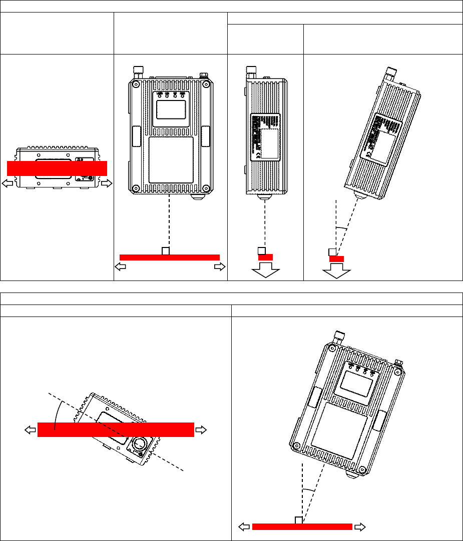
Optical alignment
Non-perpendicular alignment of the speed and length gauge to the measured object will degrade
measurement accuracy; it is recommended the gauge is installed and aligned by technicians with
metrology experience who understand the implications of even a small angular misalignment.
Correct Gauge Alignment
Roll alignment
Yaw alignment
Pitch alignment
Ideal
Acceptable for γ within ±5°
(γ ≠ 0 may be used to prevent receiver
saturation for highly-reflective objects)
Incorrect Gauge Alignment
Roll cosine error
Yaw cosine error
90°
90°
γ
90°
α
β
90°

Page 28 of 126
Proton Products SL mini and SLR mini Series Speed and Length Gauges Instruction Manual - issue 1s
Compounded roll and yaw cosine error
Measured speed = (True object speed) × cos (α) × cos (β)
Error angle α or β / degrees
cos (α) or cos (β)
Measurement error / %
0
1.000000
0.000
0.25
0.999990
-0.001
0.50
0.999962
-0.004
0.75
0.999914
-0.009
1.0
0.999848
-0.015
2.0
0.999391
-0.061
3.0
0.998630
-0.137
4.0
0.997564
-0.244
5.0
0.996195
-0.381
10
0.984808
-1.519
Page 29 of 126
Proton Products SL mini and SLR mini Series Speed and Length Gauges Instruction Manual - issue 1s
MEASUREMENT DIRECTION
SL MINI UNIDIRECTIONAL SPEED AND LENGTH GAUGE
The unidirectional SL mini speed and length gauge interprets motion in either direction as a positive
speed and an increase in length, thus correct length accumulation requires that the object must only
move in one direction (reverse motion will incorrectly cause the length to increment, not decrement).
Length measurements during line stoppage may exhibit a positive error due to microscopic vibration
of the object; hence it is recommended that the “Length hold” function on the SL mini logic input is
activated by the line controller when the line is stationary to temporarily suspend speed measurement
and length accumulation.
For production lines that require correct length accumulation during direction reversals or line
stoppage (without using the “Length hold” function), it is recommended that the SLR mini is used.
SL mini
Left to right
Right to left
Object motion direction
Count
Input
DW12.12
Rev
Direction
logic input
Speed
Length
Speed
Length
[Up]
[0]
Inactive
Positive
Incrementing
Positive
Incrementing
Down
1
Active
Negative
Decrementing
Negative
Decrementing
[ ] factory-default setting
Page 30 of 126
Proton Products SL mini and SLR mini Series Speed and Length Gauges Instruction Manual - issue 1s
SLR MINI BIDIRECTIONAL SPEED AND LENGTH GAUGE
The bidirectional SLR mini speed and length may be used for production lines that exhibit bidirectional
motion and line stoppage.
SLR mini
Left to right
Right to left
Object motion direction
Count
Input
DW12.12
Rev
Direction
logic input
Speed
Length
Speed
Length
[Up]
[0]
Inactive
Negative
Decrementing
Positive
Incrementing
Down
1
Active
Positive
Incrementing
Negative
Decrementing
[ ] factory-default setting
Mechanical mounting
It is preferable for the gauge to be mounted in isolation from the machine or production line using a
precision base plate fitted to a mounting arm (if this is not possible then the gauge must be mounted
on rubber vibration isolation mounts).The mounting arm should be kept as short as possible to avoid
vibration or twisting.
Please see the dimensional drawings for mounting hole locations.
Three M5 tapped holes are provided in the base of the gauge; select appropriate length
screws which do not bottom out in these holes.
Specification
Minimum
Typical
Maximum
Unit
Mounting surface flatness (machined flat and even)
0.15
mm
M5 mounting hole depth (do not allow bolts to bottom out)
6
mm
M5 mounting bolt torque
6
Nm
Page 31 of 126
Proton Products SL mini and SLR mini Series Speed and Length Gauges Instruction Manual - issue 1s
ELECTRICAL INSTALLATION
Earth connection
Connector type: M5 bolt
An earth wire of at least 6mm2 must be attached via a crimp on ring terminal to the dedicated
M5 earth bolt on the case of the gauge.
Do not rely on the mounting bolts to provide a reliable earth path.
If a height stand is used then it must also be earthed via its own dedicated earth wire.
All earth wires should be kept as short as possible.
Shielded Cables
Use shielded cable for all signal connections.
Ensure that all cable shields are correctly clamped and electrically connected to their
connectors and metal connector shells at both ends.
Ensure that the shields of cables connecting to the end user’s equipment are clamped to
earth at their destination.
Page 32 of 126
Proton Products SL mini and SLR mini Series Speed and Length Gauges Instruction Manual - issue 1s
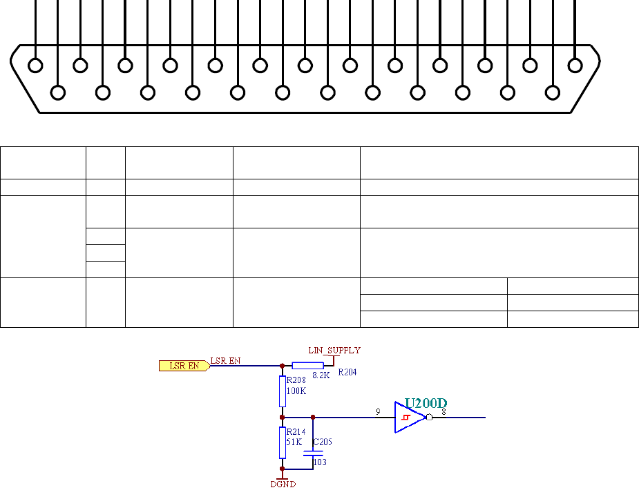
LASER ENABLE
The laser enable input is provided for compliance with laser safety regulations.
The laser diode in the gauge may be energised only if the “LSR_EN” pin (pin 14) is connected
(via an external user-supplied switch contact) to any one of the “DGND” pins (pins 2, 15, 24).
The gauge requires a few minutes for the laser temperature to stabilise and for valid
measurement after “LSR_EN” is connected to “DGND”. For this reason, it is recommended
that the laser enable input is connected to a safety interlock that is active infrequently, such
as a maintenance lock-out key switch.
Safety interlocks that are frequently activated and require the gauge to immediately resume
measurement upon deactivation (such as a machine guard door) should be connected to the
shutter enable input (“SHUT_EN”) described in the next section.
Connector type: DB25 female (socket)
Functional
group
Pin
Designation
Description
Notes
Shield
S
Shield
Shield
Connect to cable and plug shields
Power
supply and
ground
25
+24V SUPPLY
+24V power
supply
2
DGND
Power supply and
signal ground
(0V)
15
24
Laser
enable
14
LSR_EN
Laser enable
Connection
Laser diode state
Open
Off (no emission)
Connected to DGND
On (emission)
1
14
2
15
3
16
4
17
5
18
6
19
7
20
8
21
9
22
10
23
11
24
12
25
13
Page 33 of 126
Proton Products SL mini and SLR mini Series Speed and Length Gauges Instruction Manual - issue 1s
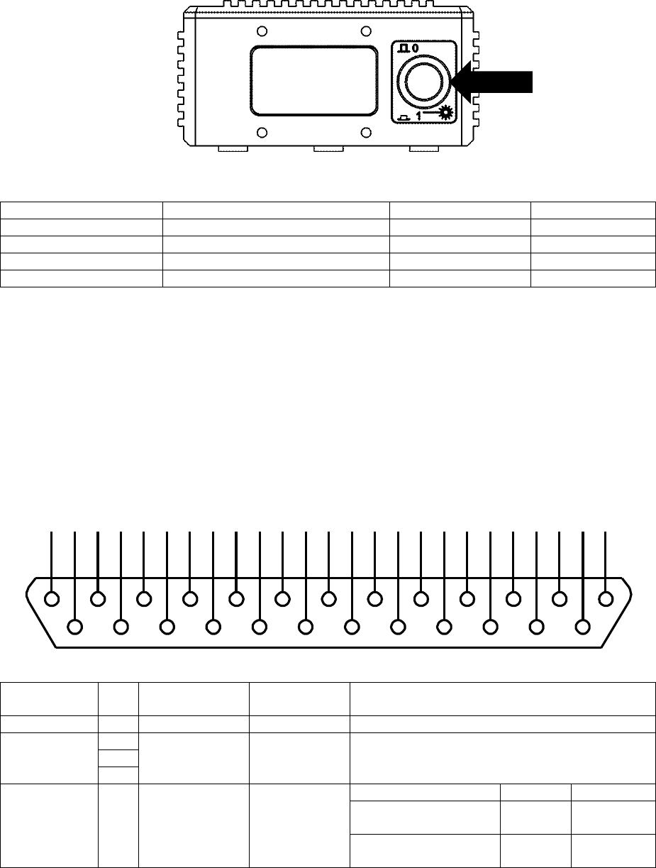
SHUTTER CONTROL SWITCH, SHUTTER ENABLE INPUT AND SHUTTER STATE
OUTPUT
The shutter control switch (located on the front of the gauge), the shutter enable input (SHUT_EN)
and shutter status output (SHUT_ST) are provided for compliance with laser safety regulations.
The SHUT_EN input and the shutter control switch operate in conjunction as follows:
SHUT_EN input
Shutter control switch position
Shutter state
Laser output
Open
O
Closed
Blocked
Open
I
Closed
Blocked
Shorted to DGND
O
Closed
Blocked
Shorted to DGND
I
Open
Emitting
The shutter control switch and SHUT_EN input blocks laser beam emission without switching
off the laser diode, thus no warm up time is required when the shutter is opened and the
gauge may be used immediately for measurements.
The SHUT_EN input is intended for connection to a safety interlock switch that may be
frequently opened, such as on a machine guard or laser safety shield.
The SHUT_ST output is electrically independent of the SHUT_EN input; the SHUT_ST signal
is taken directly from an optical sensor in the path of the shutter, thus it indicates the shutter
state even in the event of shutter actuator failure.
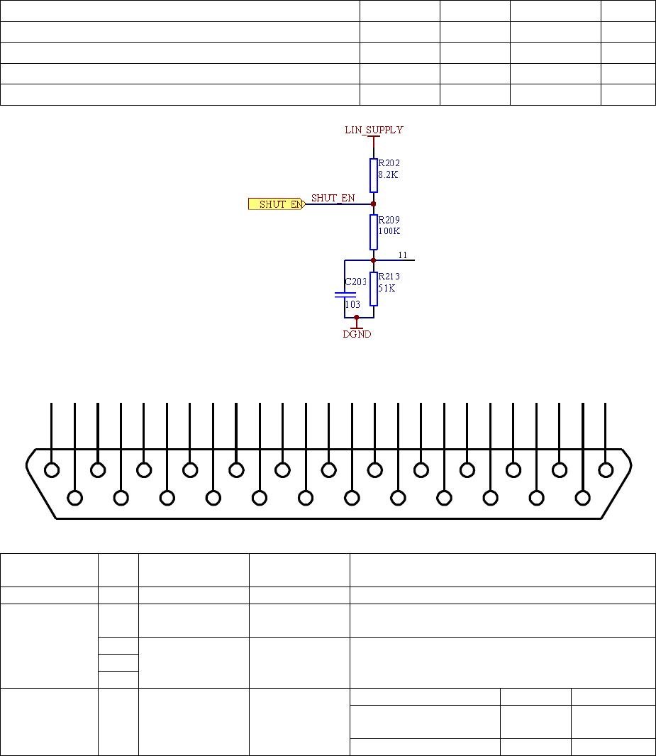
SHUT_EN input electrical specifications
Connector type: DB25 female (socket)
Functional
group
Pin
Designation
Description
Notes
Shield
S
Shield
Shield
Connect to cable and connector shields
2
DGND
Power supply
and signal
ground (0V)
15
24
Shutter
control
13
SHUT_EN
Shutter
control input
Connection
Shutter
Laser
Low state (logic 0) /
connected to DGND
Open
Emitting
High state (logic 1) /
unconnected
Closed
Blocked
1
14
2
15
3
16
4
17
5
18
6
19
7
20
8
21
9
22
10
23
11
24
12
25
13
Page 34 of 126
Proton Products SL mini and SLR mini Series Speed and Length Gauges Instruction Manual - issue 1s
The SHUT_EN input is NOT isolated from earth.
The input is internally pulled up to +15V via an 8.2kΩ resistor and will default to the high state if
left unconnected.
The input will source a minimum current of 3mA when externally pulled down to the low state.
Specification
Minimum
Typical
Maximum
Units
Low state (logic 0) input voltage
3
V
High state (logic 1) input voltage
10.5
V
Absolute input voltage
-30
30
V
Low state source current
3
mA
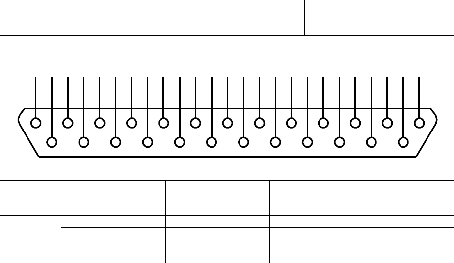
SHUT_ST output electrical specifications
Connector type: DB25 female (socket)
Functional
group
Pin
Designation
Description
Notes
Shield
S
Shield
Shield
Connect to cable and connector shields
Power
supply and
ground
25
+24V SUPPLY
+24V power
supply
2
DGND
Power supply
and signal
ground (0V)
15
24
Shutter
control
12
SHUT_ST
Shutter
status output
Signal
Shutter
Laser
Pulled down to
DGND
Open
Emitting
Floating
Closed
Blocked
The SHUT_ST output is NOT isolated from earth.
The SHUT_ST output must NOT be used to directly drive high-current or inductive loads.
It is recommended that the SHUT_ST output is used to drive an opto-isolated solid-state
relay.
1
14
2
15
3
16
4
17
5
18
6
19
7
20
8
21
9
22
10
23
11
24
12
25
13

Page 35 of 126
Proton Products SL mini and SLR mini Series Speed and Length Gauges Instruction Manual - issue 1s
Specification
Minimum
Typical
Maximum
Units
Logic output to DGND voltage
+25
VDC
Current
0.1
A
Page 36 of 126
Proton Products SL mini and SLR mini Series Speed and Length Gauges Instruction Manual - issue 1s
POWER SUPPLY
Specification
Minimum
Typical
Maximum
Units
Power supply voltage*
15
24
28
VDC
Power consumption
15
W
*If a long power supply cable with a significant voltage drop is used, then ensure that the voltage at
the gauge connector does not fall below the minimum value.
Connector type: DB25 female (socket)
Functional
group
Pin
Designation
Description
Notes
Shield
S
Shield
Shield
Power
supply
25
+24V SUPPLY
+24V power supply
2
DGND
Power supply and
signal ground (0V)
15
24
Powering on the gauge
The gauge has no power switch; as soon as power is applied it will power up and perform some self-
tests. Measurement will begin after a warm-up period of a few minutes required for the temperature of
internal components to stabilise.
Powering off the gauge
The gauge has no power switch; it may be powered off by switching off or disconnecting the power
supply to the unit.
1
14
2
15
3
16
4
17
5
18
6
19
7
20
8
21
9
22
10
23
11
24
12
25
13
Page 37 of 126
Proton Products SL mini and SLR mini Series Speed and Length Gauges Instruction Manual - issue 1s
CONFIGURATION
The SL mini and SLR mini series of speed and length gauges may be configured using a PC running
the PCiS_SLmini software.
PCIS_SLMINI SOFTWARE PC SYSTEM REQUIREMENTS
Minimum processor
Pentium 300 MHz CPU compatible or higher
Minimum RAM
512 MB
Minimum free hard disk space
100 MB
Display resolution
1024 x 768
Operating system
Microsoft Windows XP / Windows 7 / Windows 8
Other requirements
100Base-TX Ethernet port or adapter card
RS-232 port or USB port and USB to RS-232 adaptor cable
Keyboard and mouse (for configuration and software installation)
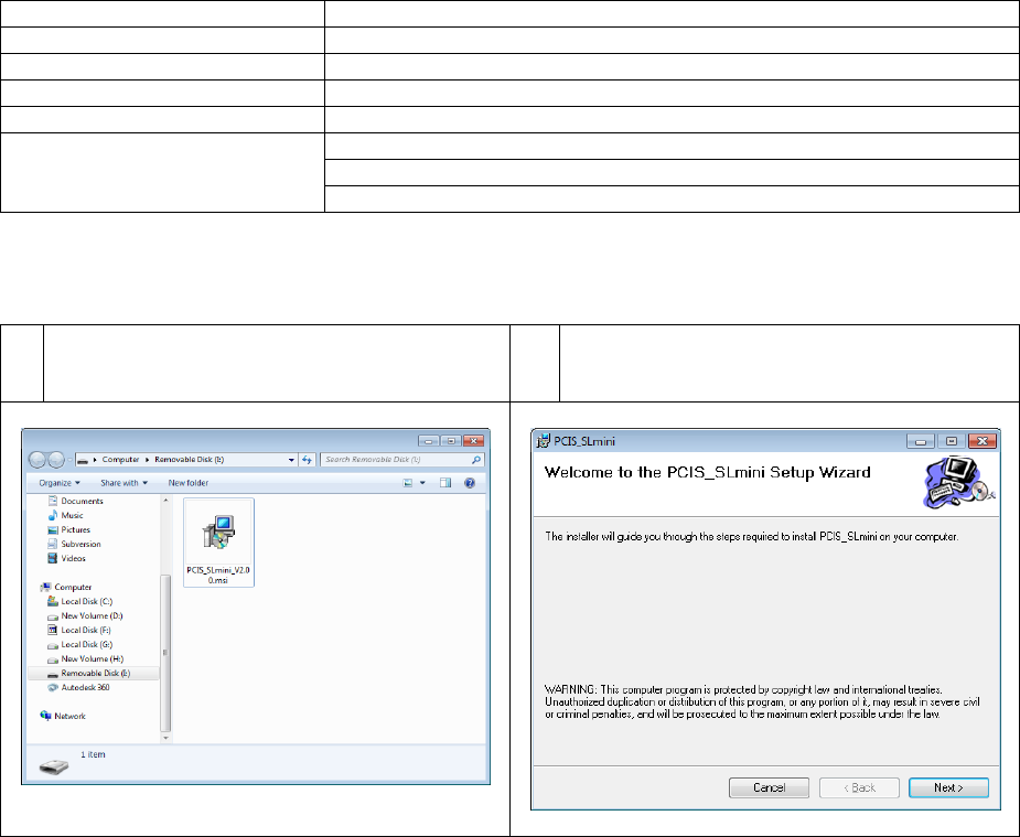
PCIS_SLMINI SOFTWARE INSTALLATION
1
Double-click the “PCIS_SLmini_Vx.yy.msi”
icon on the supplied USB flash memory drive
(“x.yy” will depend on the software version).
2
Click “Next >” to proceed with the
installation.
Page 38 of 126
Proton Products SL mini and SLR mini Series Speed and Length Gauges Instruction Manual - issue 1s
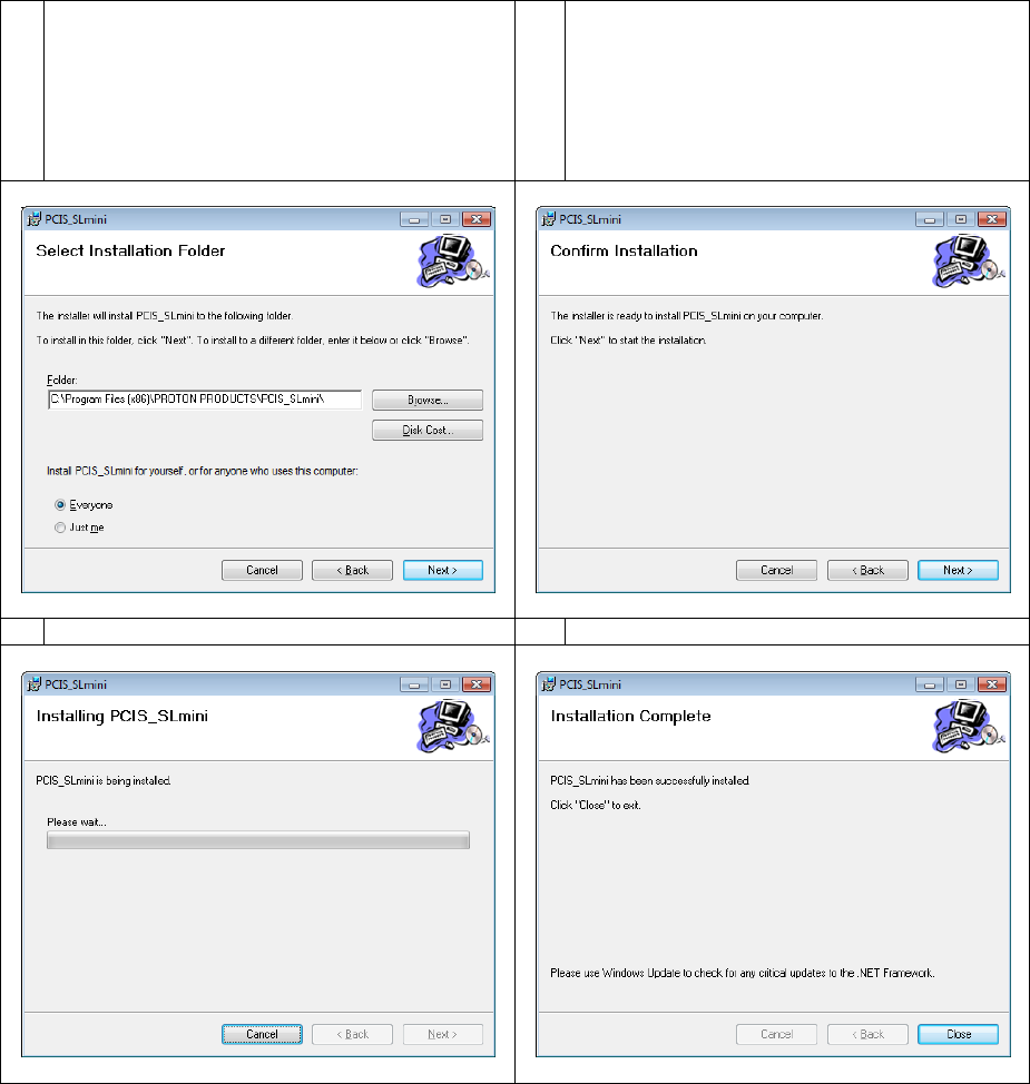
3
If required, click “Browse” to select an
alternative installation folder.
If required, click “Just me” to limit access to
this program to the current user.
Click “Next >” to proceed with the installation.
4
Click “Next >” to proceed with the
installation.
5
Wait for the installation to complete.
6
Click “Close” to finish installation.
CONNECTION AND SOFTWARE START UP
A PC running the PCiS_SLmini software may be connected to the gauge using any one of the
following communications interfaces:
RS-232 (fitted as standard on all gauges).
Ethernet (only available if NO other optional communications interface has been installed).
EtherNet/IP (only available if the gauge has been installed with the optional EtherNet/IP
communications interface)
PROFINET (only available if the gauge has been installed with the optional PROFINET
communications interface)
Note: For gauges communicating over either optional EtherNet/IP or PROFINET communications
interfaces, only input and output parameters DW0 to DW31 are visible to the PCiS software.
Page 39 of 126
Proton Products SL mini and SLR mini Series Speed and Length Gauges Instruction Manual - issue 1s
The above communications interfaces may be directly accessed via the DB25 “INTERFACE”
connector on the rear of the gauge or via a PSU-BOB mini connected to the “INTERFACE” port; for
wiring information, please refer to the following sections in this manual:
RS-232 Communications
Ethernet Communications
EtherNet/IP or PROFINET Communications
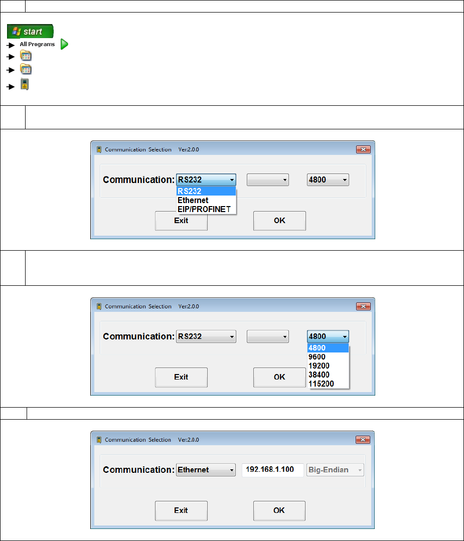
1
Run the PCIS_SLmini software by clicking on:
PROTON PRODUCTS
PCIS_SLmini
PCIS_SLmini
2
Select the interface type (choose from “RS232”, “Ethernet” or “EIP/PROFINET”) from the drop-
down menu:
3a
If using the “RS232” interface, select the COM port on the PC to which the gauge is connected
and the baud rate (choose from “4800”, “9600”, “19200”, “38400” or “115200”; the factory default
is “9600”) from the drop-down menus:
3b
If using the “Ethernet” interface, enter the IP address of the gauge:
“EIP/PROFINET”
Page 40 of 126
Proton Products SL mini and SLR mini Series Speed and Length Gauges Instruction Manual - issue 1s
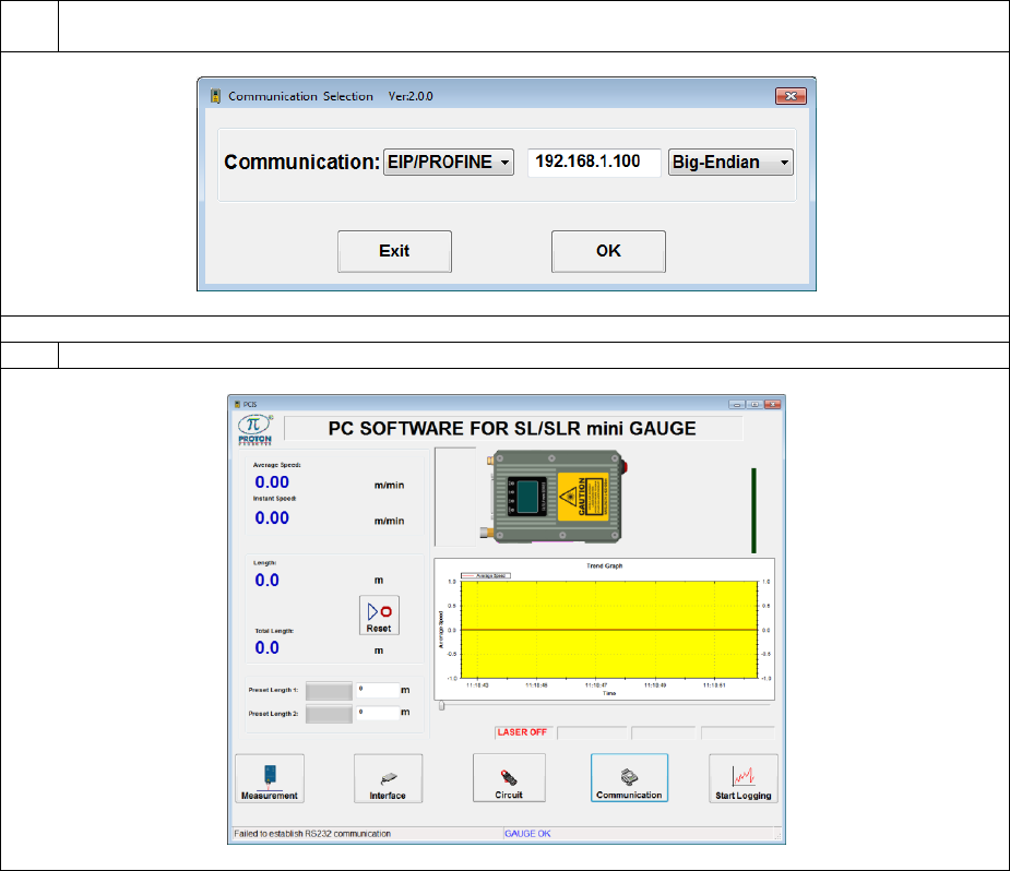
3c
If using the “EIP/PROFINET” interface, enter the IP address of the gauge and select “Big-
Endian” or “Little-Endian” data format (the factory-default is “Big-Endian”):
4
Click the “OK” button to proceed.
Page 41 of 126
Proton Products SL mini and SLR mini Series Speed and Length Gauges Instruction Manual - issue 1s
WIFI CONFIGURATION
The WIFI function can be configured via the PCiS_SLmini software after a PC connection is
established with the gauge.
1
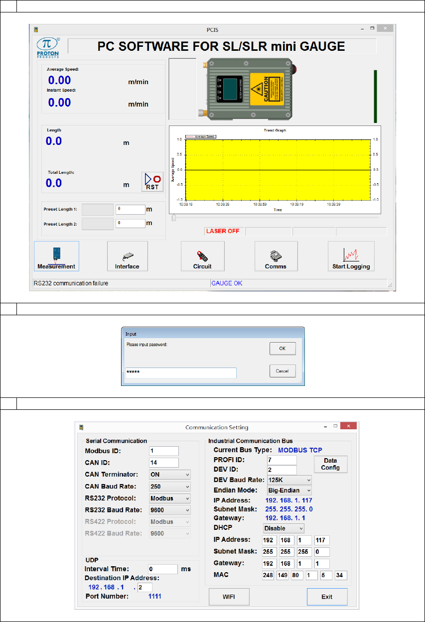
Click the “Comms” button on the main page:
2
When prompted to input a password, enter “65000” then click the “OK” button:
3
Click the “’WIFI” button on the Communication Setting page:
Page 42 of 126
Proton Products SL mini and SLR mini Series Speed and Length Gauges Instruction Manual - issue 1s
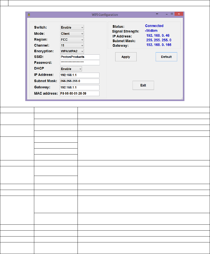
4
Configure the WIFI interface as required then click the “Apply” button when complete.
Label
Value
Description
Switch
Enable
Switch on the WIFI function.
Disable
Switch off the WIFI function.
Mode
Client mode
The gauge acts as a client device in client mode.
AP mode
The gauge acts as an access point in AP mode.
Region
OTHER
Select the region where the gauge is located.
ETSI
FCC
JAPAN
Channel
1~11
Select the radio channel for the gauge.
Encryption
OPEN
Select the network encryption method.
WPA/WPA2
SSID
******
Enter the SSID of the network.
Password
******
Enter the password of the network.
DHCP
Enable
Select this option to enable the gauge to automatically
acquire its IP address, subnet mask and gateway from a
DHCP server on the network.
Disable
Select this option to manually configure the gauge IP
Address, subnet mask and gateway in the fields below.
IP Address
[192.168.1.1]
Enter the IP address assigned to the gauge.
Subnet Mask
[255.255.255.0]
Enter the subnet mask for the network.
Gateway
[192.168.1.1]
Enter the gateway IP address for the network.
MAC
Address
xx-xx-xx-xx-xx-xx
Enter the physical MAC address of the WIFI chip.
* [ ] indicates factory-default values.
Note: To restore the gauge to factory-default network settings, click the “Default” button. See the
table above for the factory-default values.
Page 43 of 126
Proton Products SL mini and SLR mini Series Speed and Length Gauges Instruction Manual - issue 1s
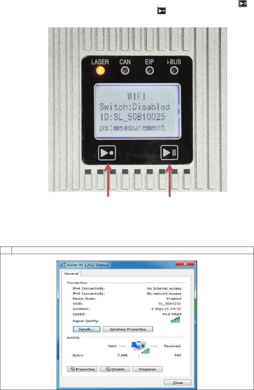
The WIFI function can also be enabled or disabled manually using the physical hardware buttons on
the gauge. To do this, first enter the WIFI interface configuration screen by long pressing (the
pause button) while the gauge is powering on. Then press (the reset button) to enable or disable
the WIFI function. Press the pause button to exit the WIFI interface configuration screen.
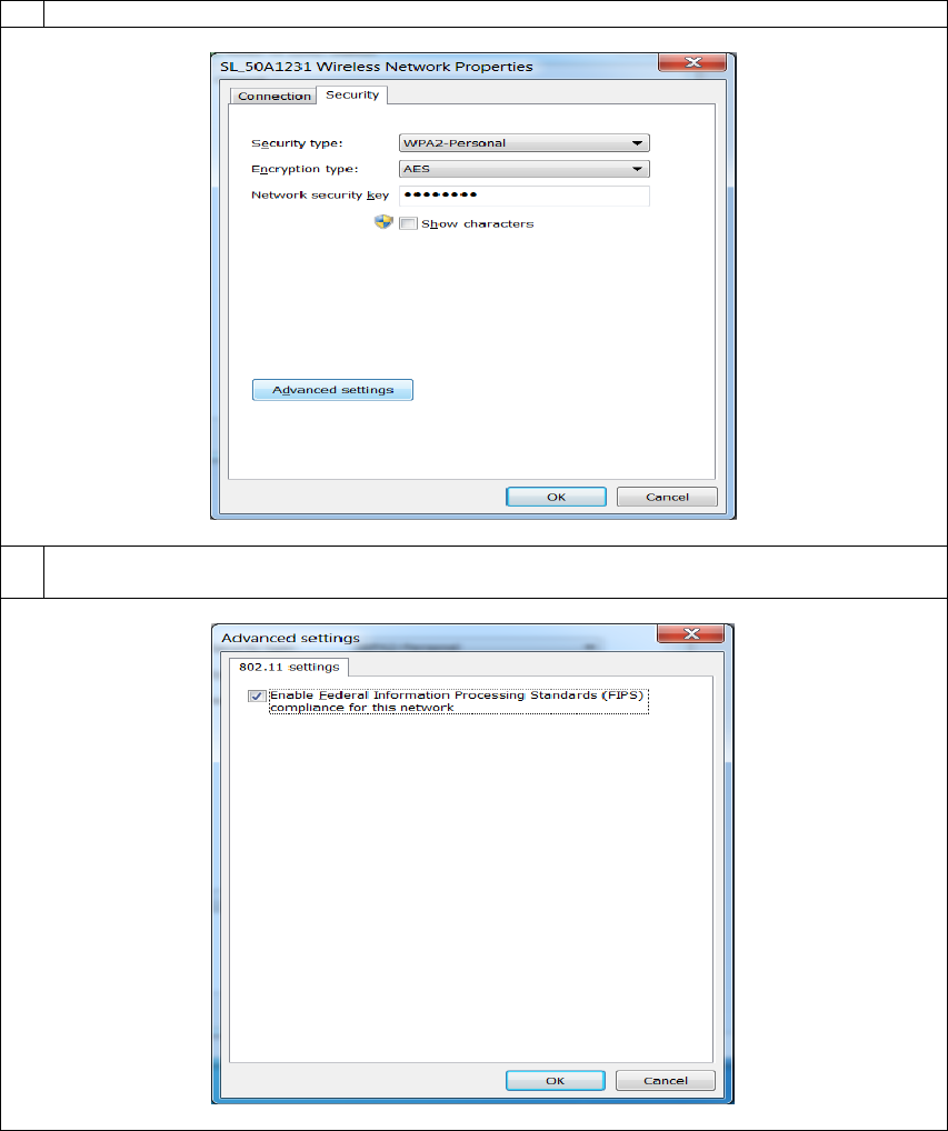
In the event of communication issues, it may be necessary to enable the Federal Information
Processing Standards (FIPS) compliance on the PC connected with the gauge. To enable the FIPS
compliance, please use the following procedure:
1
Open the Status window for the PC’s WIFI adapter and click the “Properties” button.
Reset button
Pause button
Page 44 of 126
Proton Products SL mini and SLR mini Series Speed and Length Gauges Instruction Manual - issue 1s
2
Click the Advanced settings button on the Security tab.
3
Check the tick box next to “Enable Federal Information Processing Standards (FIPS)
compliance for this network” then click the “OK” button.
Page 45 of 126
Proton Products SL mini and SLR mini Series Speed and Length Gauges Instruction Manual - issue 1s
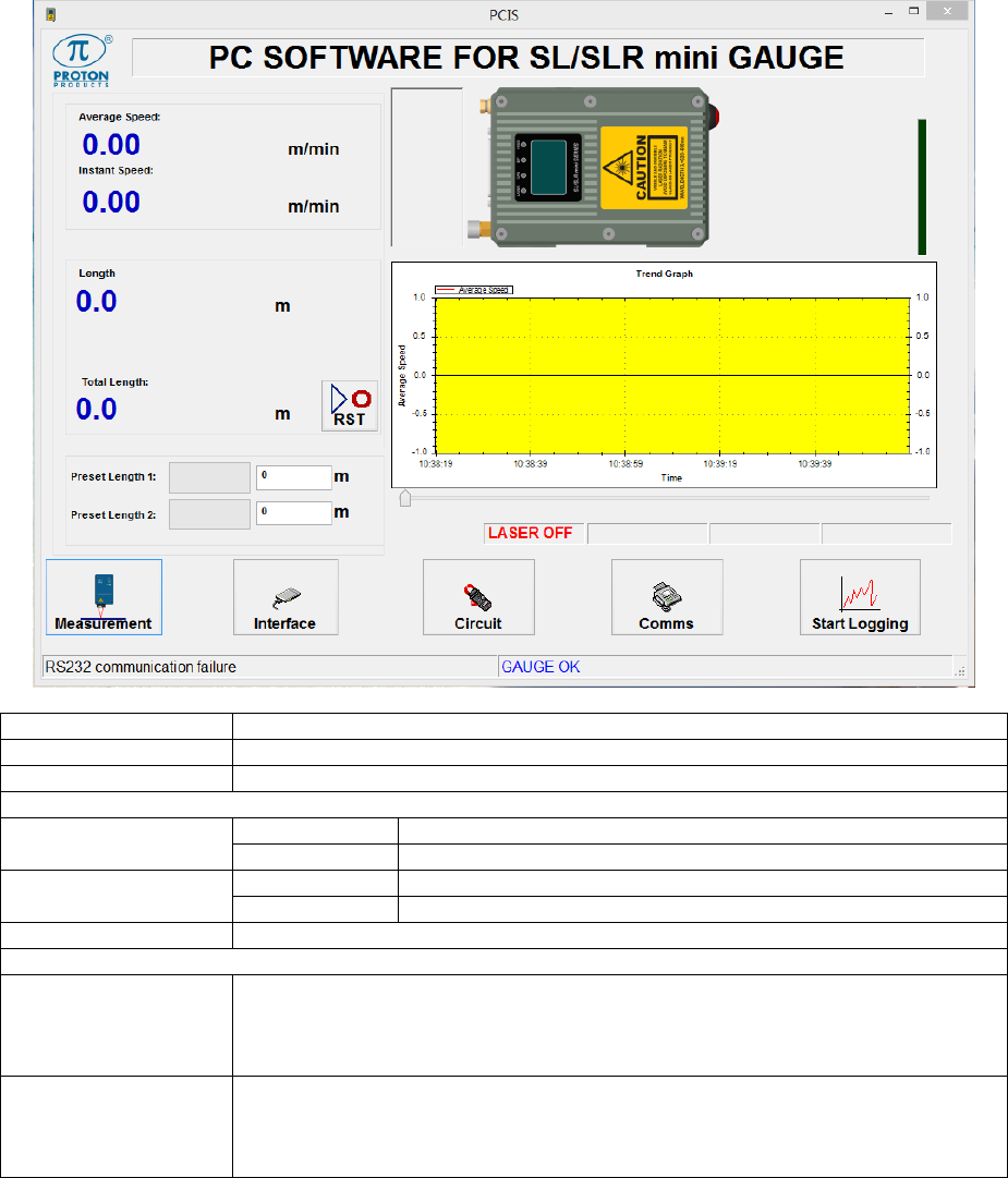
PCIS_SLMINI MAIN PAGE
Label
Description
Average Speed
Displays the time-averaged measured object speed.
Instant Speed
Displays the instantaneous measured object speed.
Length
Normal mode
Displays the measured length.
Batch mode
Displays the measured length of the current segment.
Total Length
Normal mode
Displays the measured length (identical to “Length” above).
Batch mode
Displays the total measured length of all segments.
Reset
Click this button to reset the measured “Length” and “Total Length” to zero.
Preset Length 1
Click to enter “Preset Length 1” at which the corresponding logic output is
activated.
The bar graph indicates the measured length relative to this preset.
Preset Length 2
Click to enter “Preset Length 2” at which the corresponding logic output is
activated.
The bar graph indicates the measured length relative to this preset.
Page 46 of 126
Proton Products SL mini and SLR mini Series Speed and Length Gauges Instruction Manual - issue 1s
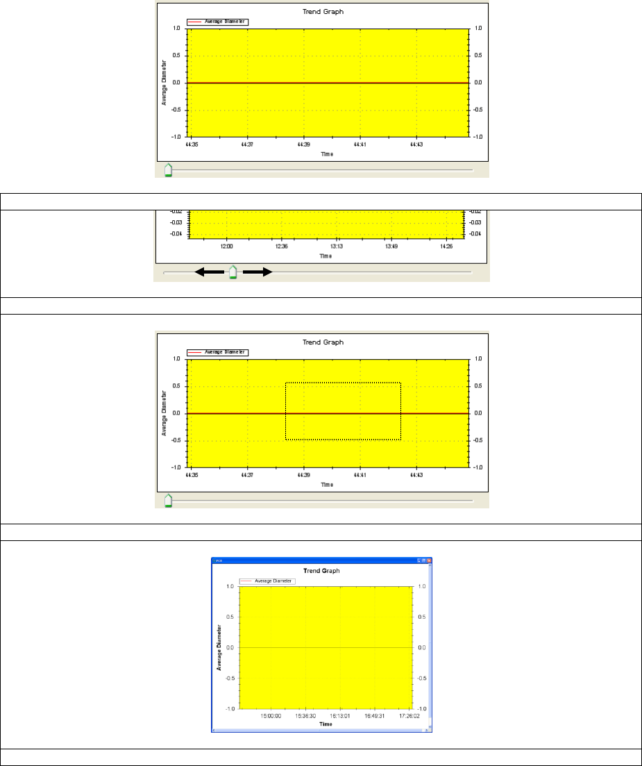
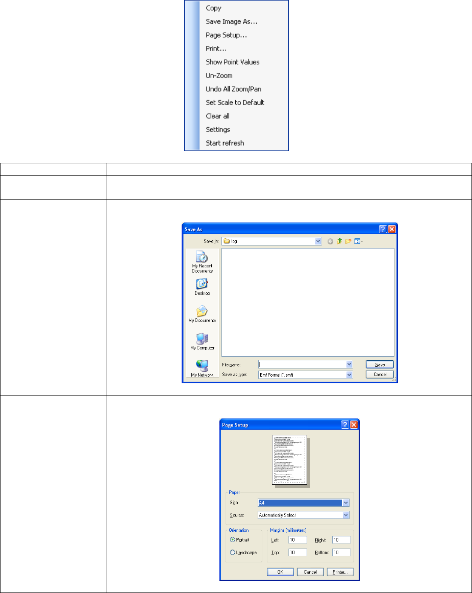
TREND GRAPH
Drag the slider at the bottom of the graph to pan along the graph:
Click and drag to zoom in on the graph:
Double-click on the graph to open it in a larger window:
Double-click on the graph to return to the main page.
Page 47 of 126
Proton Products SL mini and SLR mini Series Speed and Length Gauges Instruction Manual - issue 1s
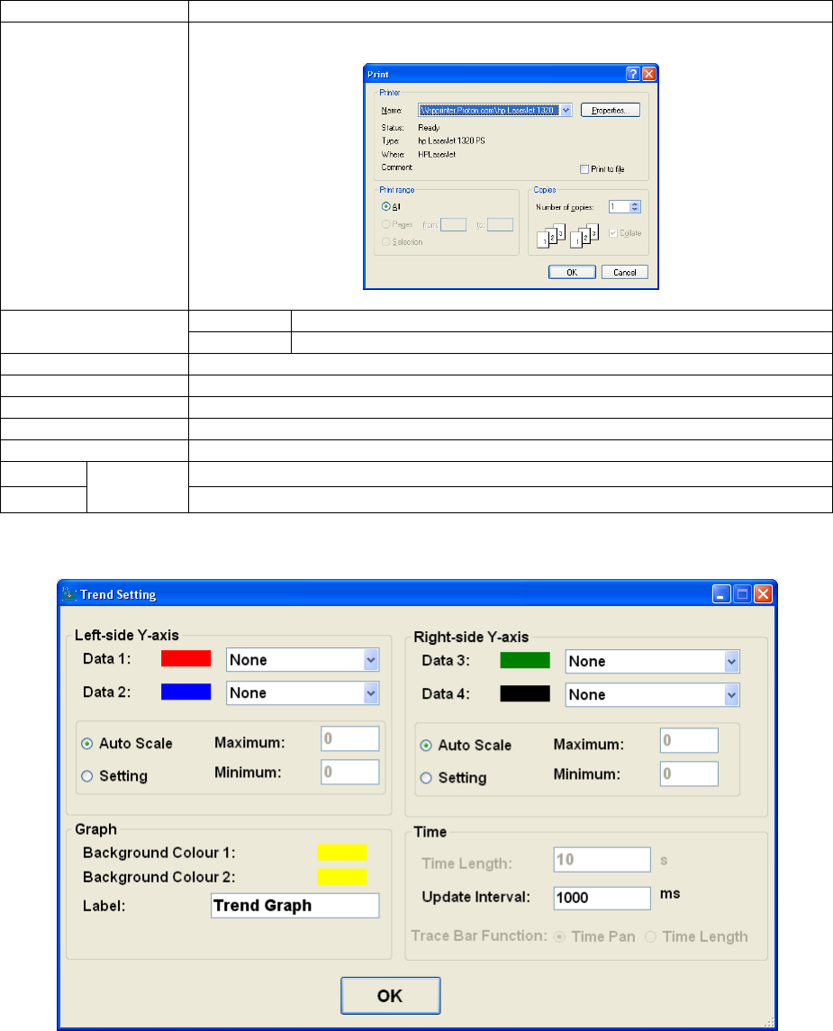
Context menu
Right-click on the graph to open the context menu:
Field
Description
Copy
Copy the image of the graph to the clipboard (for subsequent pasting into
other documents).
Save Image As…
Save an image of the graph to a file:
Page Setup…
Open the “Page Setup” dialog box for printing the graph:
Page 48 of 126
Proton Products SL mini and SLR mini Series Speed and Length Gauges Instruction Manual - issue 1s
Field
Description
Print…
Open the “Print” dialog box for printing the graph:
Show Point Values
Ticked
Show the value of the point on the graph under the cursor.
Un-ticked
Do not show the value of the point on the graph under the cursor.
Un-Zoom
Return to the un-zoomed view of the graph.
Undo All Zoom/Pan
Return to the un-zoomed, un-panned view of the graph.
Set Scale to Default
Return to default scale settings.
Clear all
Clear the current graph and begin plotting from the left side of the time axis.
Settings
Open the graph settings dialog box (see below).
Stop
refresh
Halt graph update.
Start
Resume graph update.
Settings
Click the “OK” button to return to the main page.
Page 49 of 126
Proton Products SL mini and SLR mini Series Speed and Length Gauges Instruction Manual - issue 1s
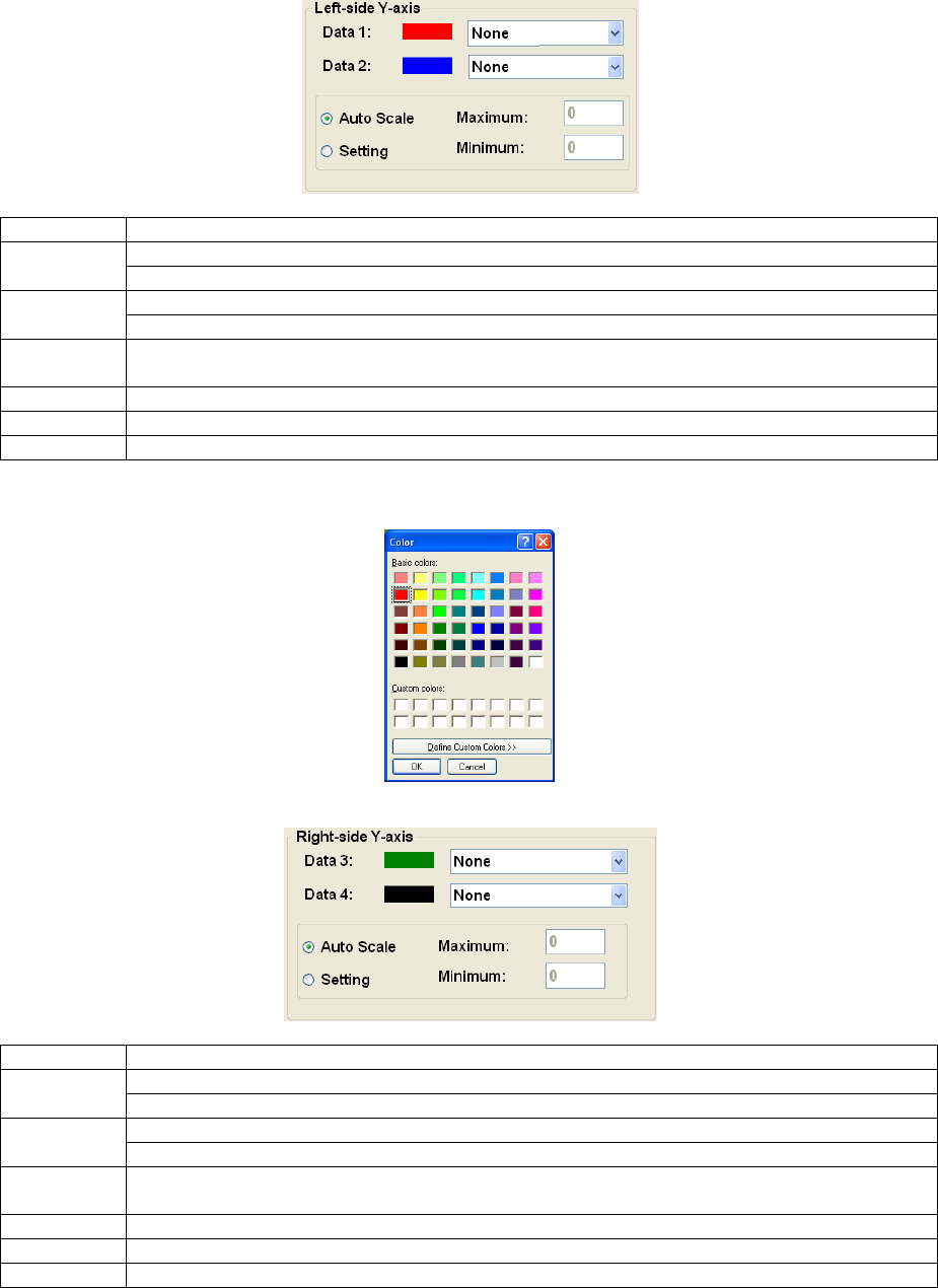
Left-side Y-axis
Field
Description
Data 1
Click on the drop down box to select the data plotted on this axis.
Click on the coloured box to select the line colour.
Data 2
Click on the drop down box to select the data plotted on this axis.
Click on the coloured box to select the line colour.
Auto Scale
Click to allow the software to automatically set the minimum and maximum values for
this axis.
Setting
Click to manually set “Maximum” and “Minimum” values for this axis.
Maximum
Click to enter the maximum value for this axis.
Minimum
Click to enter the minimum value for this axis.
Clicking on “Data” or colour boxes will open the colour selection dialog:
Right-side Y-axis
Field
Description
Data 3
Click on the drop down box to select the data plotted on this axis.
Click on the coloured box to select the line colour.
Data 4
Click on the drop down box to select the data plotted on this axis.
Click on the coloured box to select the line colour.
Auto Scale
Click to allow the software to automatically set the minimum and maximum values for
this axis.
Setting
Click to manually set “Maximum” and “Minimum” values for this axis.
Maximum
Click to enter the maximum value for this axis.
Minimum
Click to enter the minimum value for this axis.
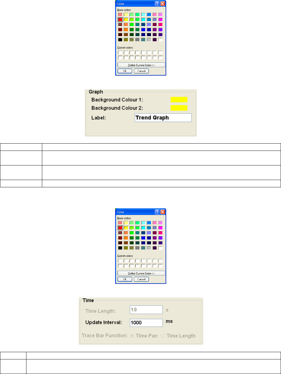
Page 50 of 126
Proton Products SL mini and SLR mini Series Speed and Length Gauges Instruction Manual - issue 1s
Clicking on “Data” or colour boxes will open the colour selection dialog:
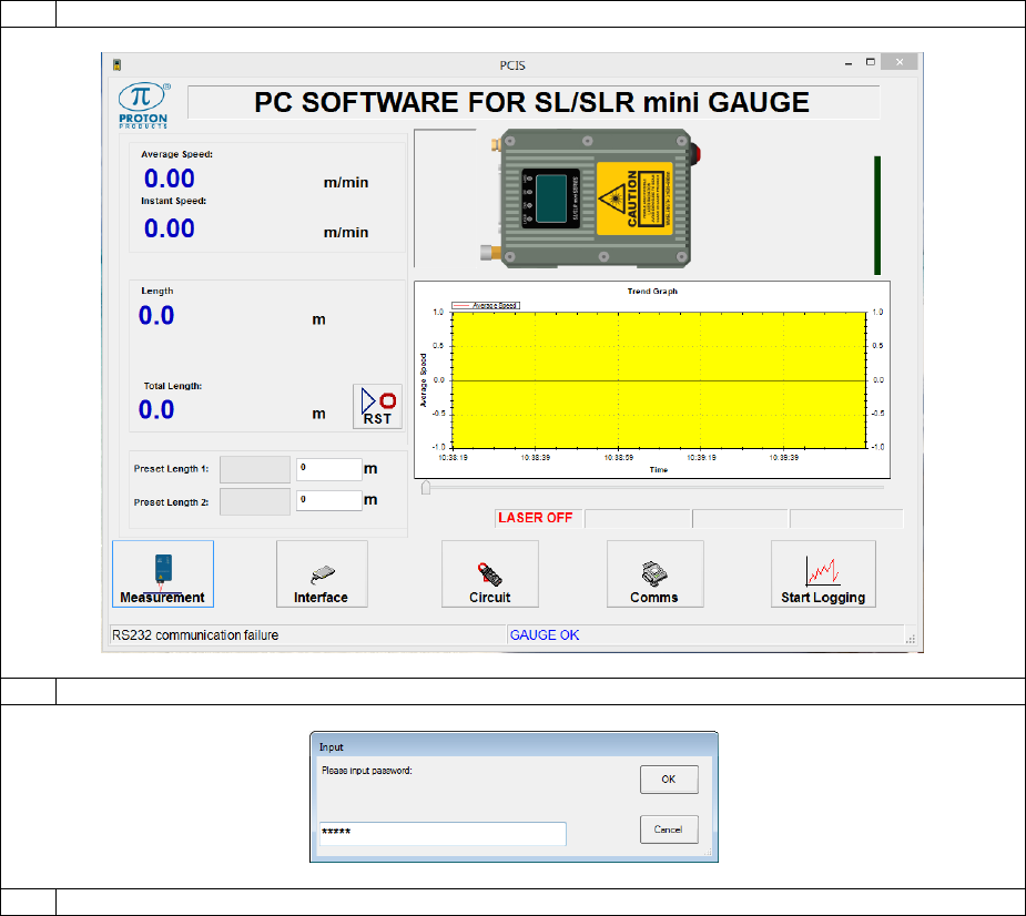
Graph
Field
Description
Background
Colour 1
Click on the coloured box to select the top left corner background colour for the graph;
this colour will be graded across the graph to “Background Colour 2”.
Background
Colour 2
Click on the coloured box to select the bottom right corner background colour for the
graph; this colour will be graded across the graph to “Background Colour 1”.
Label
Click to enter a title for the graph.
Clicking on “Background Colour” colour boxes will open the colour selection dialog:
Time
Field
Description
Update
interval
Set the time interval at which data is updated on the graph; a shorter time interval will result
in a more detailed graph, whilst a longer time interval is clearer at showing long-term trends.
Page 51 of 126
Proton Products SL mini and SLR mini Series Speed and Length Gauges Instruction Manual - issue 1s
MEASUREMENT CONFIGURATION
Configuration via the PCiS_SLmini software:
1
Click the “Measurement” button on the main page:
2
When prompted, enter 63000 for the password and click the “OK” button:
3
Configure the gauge as required and click the “Exit” button when complete:

Page 52 of 126
Proton Products SL mini and SLR mini Series Speed and Length Gauges Instruction Manual - issue 1s
Label
Value*
Description
Input
DW
Operation
Mode
[Normal]
See the section below to determine the appropriate
operation mode.
0.0
Batch
Measurement
Unit
[Meter]
Select for length measurement in metres and speed
measurement in meters per minute
0.3-4
Feet
Select for length measurement in feet and speed
measurement in feet per minute.
Yards
Select for length measurement in yards and speed
measurement in yards or feet per minute.
Inch
Select for length measurement in inch and speed
measurement in feet per minute.
Length Speed
Resolution
0.1 & 0.01
Select to set the length resolution to 0.1 units and speed
resolution to 0.01 units/minute, where the units are
metres, feet or yards depending on the “Measurement
Unit” setting.
0.8
[0.0001 & 0.001]
Select to set the length resolution to 0.0001 units and
speed resolution to 0.001 units/minute, where the units
are metres, feet or yards depending on the
“Measurement Unit” setting.
Speed
Decimal Point
0
Set the number of digits after the decimal point to be
displayed for the measured speed.
-
0.0
0.00
0.000
Length
Decimal Point
0
Set the number of digits after the decimal point to be
displayed for the measured length.
-
0.0
0.00
0.000
0.0000
Object
Detection
[OFF]
See the section below for information on “Object
Detection” mode.
0.11
ON

Page 53 of 126
Proton Products SL mini and SLR mini Series Speed and Length Gauges Instruction Manual - issue 1s
Auto Reset
When Object
Detected
[OFF]
Accumulate the length measurement across all discrete
objects.
0.12
ON
Reset the length measurement on detection of the next
discrete object.
Object
Detection
Threshold
0 ~ [15] ~100%
Set a DC level percentage threshold above which an
object is considered as present.
-
Length Auto
Save
[OFF]
The length measurement will be reset to zero when the
gauge is powered-up.
0.10
ON
The length measurement just prior to a power
interruption is stored in non-volatile memory and will
resume from this stored value on subsequent power-up.
Speed
Averaging
Time
5 ~ [200] ~
5000ms
Set the time period (in milliseconds) over which the
measured speed is averaged.
A longer averaging period results in a more stable speed
measurement (and pulse output rate) which is less
sensitive to small and sudden speed changes.
2
Hold Time
1 ~ [100] ~
5000ms
Set the time to hold the last speed measurement after
speed signal loss.
The “Hold Time” should be set to a sufficiently long
period to cover any momentary speed signal dropouts
due to surface irregularities on the measured object.
3
Length Offset
-3000.0 ~
3000.0
m{ft}{yds}{inch}
Set the length offset value.
For an object threaded through the production line, the
unmeasured length located beyond the gauge may be
entered here (as a positive value) to add to the
measured length to yield the correct total length.
14
Speed
Compensation
[1.0000]
Set a value other than the default value of 1.0000 to
apply a compensation factor to the measured speed.
38
Minimum
Speed Limit
[0] ~ 6553.5
m{ft}{yds}/min
Set the minimum speed at which the gauge is required
to measure speed; for speeds below this value, the
gauge will register a speed of zero.
This value may be set to avoid drift in the measured
length when the object is stationary due to measurement
noise.
11
Acceleration
Limit
1 ~ [9999]
m{ft}{yds}/min/s
Not currently in use.
39
Reel Number
Displays the current reel number.
The “Reel Number” may be incremented by activation of
a logic input configured for the “End of Reel” function.
-
Panel Key
Button Switch
[Enabled]
When “Enable” is selected, the two buttons (Reset and
Pause) located on the LCD display of the gauge will be
active.
Disabled
When “Disable” is selected, the two buttons (Reset and
Pause) located on the LCD display of the gauge will be
inactive to avoid wrong operations.
Reset
Click to reset the “Reel Number” to zero.
The “Reel Number” may also be reset by activation for
longer than 5 seconds of a logic input configured for the
“Reset” function.
Test
The “Test” function simulates the measurement of a user set speed by the
gauge even when there is no object being measured; pulse outputs will
generate pulses corresponding to the “Preset Speed”.

Page 54 of 126
Proton Products SL mini and SLR mini Series Speed and Length Gauges Instruction Manual - issue 1s
Speed Mode
Normal
Select for normal operation.
44
Simulation
Select for simulated measurement.
Random
Unticked
The gauge will behave as if it is measuring the “Preset
Speed”.
-
Ticked
The gauge will behave as if it is measuring a randomly
changing speed.
Preset Speed
0 ~[100]
~6553.5
m{ft}{yds}/min
Set the required simulation speed measurement.
45
Current
Speed
This indicates the current simulated speed.
-
Parameters
The “Parameters” section is for bulk saving and loading of parameters
settings to and from a file.
Load
Load parameters from a file.
-
Save
Save current parameters to a file.
-
Factory
Default
Restore parameters to their factory default values.
40
Exit
Click to return to the main page.
-
* factory-default values are shown in enclosed in [ ].
{} indicates alternative units depending on the “Measurement Unit” setting.
Normal Operation Mode
In “Normal” operation mode, the user may set two length presets (“Preset Length 1” and “Preset
Length 2”).
Whenever the measured length exceeds any length preset, the corresponding logic output assigned
to that length preset will be activated (pulled-low).
The logic output will be deactivated (floating) when:
The measured length is reset to zero by:
o Activating a logic input configured for the “Reset” function.
o Clicking the PCiS_SLmini software “Reset” button.
o Writing logic 1 to input parameter DW0.1.
The measured length falls below the length preset (applicable only to the SLR mini when the
measured length is decrementing due to line direction reversal).
Batch Operation Mode
“Batch” operation mode is used when a continuous object is being measured for marking (e.g. by an
inkjet printer) or cutting (e.g. by a guillotine) at regular intervals.
In “Batch” mode, the user may set a “Batch Length” and a “Batch Number”.
As each “Batch length” segment of the object is measured, the corresponding logic output assigned to
the “Batch Length” function will be momentarily activated (pulled-low; the activation time may be
configured by the user).
When the total number of segments measured equals or exceeds the “Batch Number”, then the
corresponding logic output assigned to the “Batch Number” function, will be activated (pulled-low).
The real-time measured segment and total lengths may be viewed using the PCiS_SLmini software or
read out of the gauge from output parameters DW6-7 and DW12-13 respectively. The current
segment number may be read from output parameter DW10.
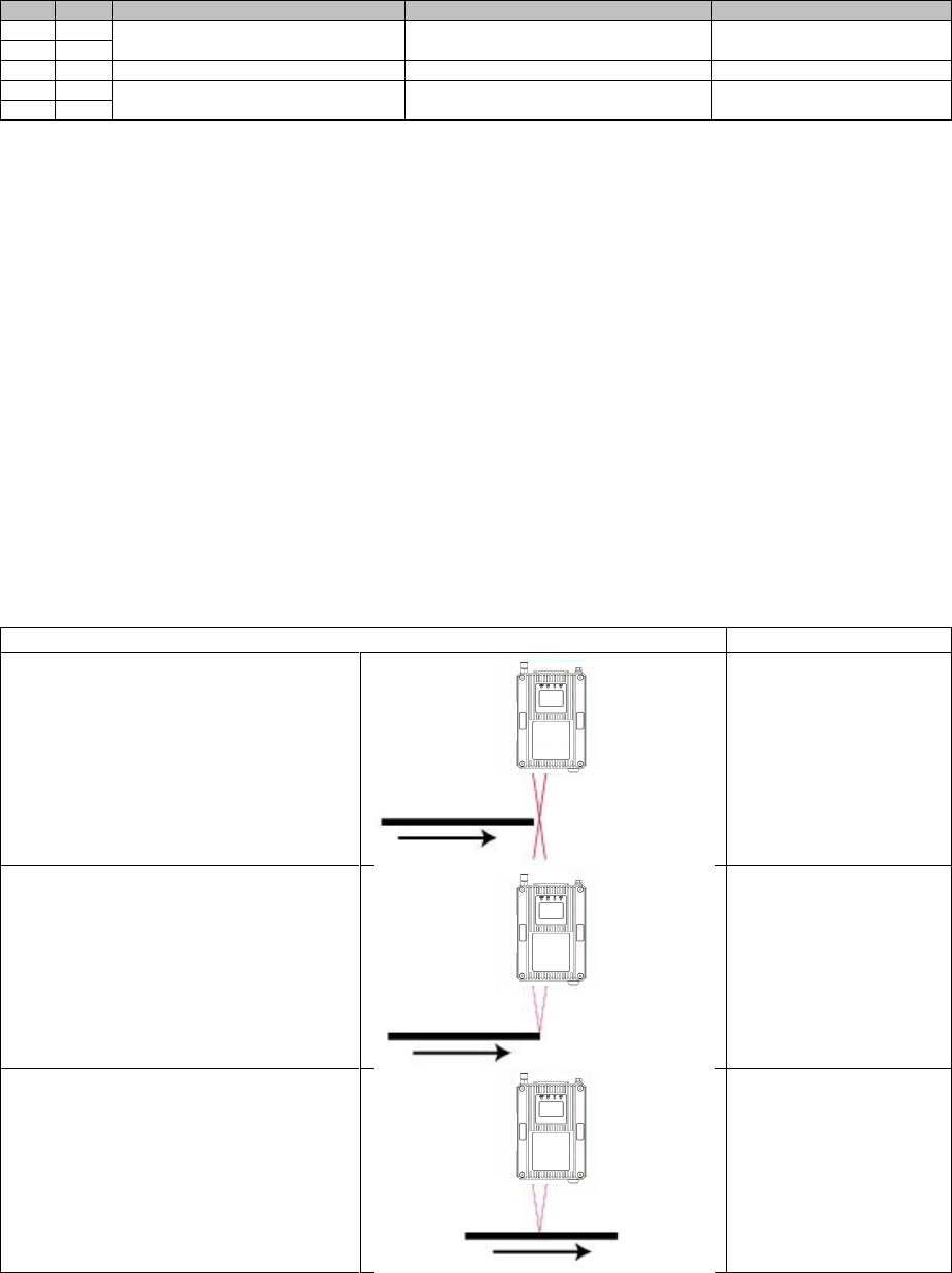
Page 55 of 126
Proton Products SL mini and SLR mini Series Speed and Length Gauges Instruction Manual - issue 1s
DW
Bit
Comments
Units
Range/Remark
6
Length
Old format: 1=0.1m{ft}{yds}{inch}
New format: 1=0.0001m{ft}{yds}{inch}
±200,000.0000
7
10
Batch number
1=1
12
Total length
1=0.1m{ft}{yds}{inch}
±200,000.0000
13
The “Batch Number” logic output will be deactivated (floating) when the measured length is reset to
zero by:
Activating a logic input configured for the “Reset” function.
Clicking the PCiS_SLmini software “Reset” button.
Writing logic 1 to input parameter DW0.1.
Object Detection Mode
The “Object Detection” mode is used when measuring the speed and length of discrete objects (e.g.
multiple separate parts on a conveyor belt). The “Object Detection” mode forces the speed reading to
zero when no object is present.
An object is determined as present if the detected DC level (in percent) exceeds the “Object Detection
Threshold”; the factory default value for this threshold is 15% and it may be adjusted on the
“Measurement” page of the PCiS_SLmini software in the event of incorrect object detection
behaviour.
Status
Speed measurement
No object detected
0 (zero)
Object detected
Maximum leading edge reaction
time: 1ms delay after the object
blocks the laser beams)
Line speed
Object detected
Line speed
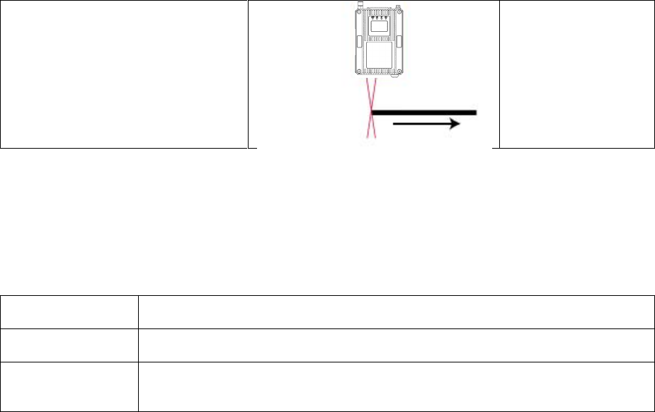
Page 56 of 126
Proton Products SL mini and SLR mini Series Speed and Length Gauges Instruction Manual - issue 1s
No object detected
Maximum trailing edge reaction time:
1ms delay after the object unblocks
the laser beams
0 (zero)
The “Object Detection” mode may be configured to automatically reset the measured length when a
new object is detected:
Auto Reset When
Object Detected*
Length measurement behaviour
[OFF]
The gauge measures the total length accumulated across multiple discrete
objects.
ON
The gauge measures the length of each individual discrete object; detection of
the next object resets the length measurement to zero so that only the length of
the next object is measured.
* [ ] indicates the factory-default setting.
“Hold Time” behaviour in “Object Detection” mode
In “Object Detection” mode, the “Hold Time” only applies when an object is detected.
If an object is detected, but the speed signal is momentarily lost (possibly due to a surface defect on
the object), then the gauge will hold the last speed measurement for the “Hold Time” period and
accumulate length accordingly during this period.
The “Hold Time” should be set to a sufficiently long period to cover any momentary speed signal
dropouts due to surface irregularities on the measured object.
When an object is not detected, the gauge will NOT hold the last speed measurement (or accumulate
length).
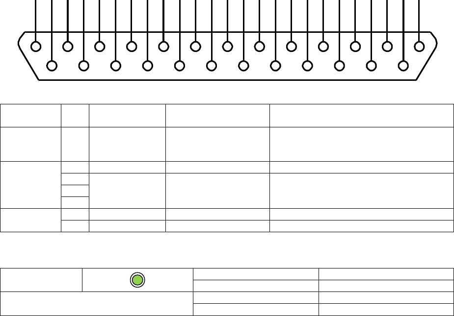
Page 57 of 126
Proton Products SL mini and SLR mini Series Speed and Length Gauges Instruction Manual - issue 1s
STANDARD COMMUNICATIONS INTERFACES
CAN-BUS COMMUNICATIONS
This CAN-bus interface is fitted as standard. It operates independently of the other communications
interfaces and may be accessed at the same time as them.
The CAN-bus interface uses a proprietary Proton Products protocol. It is exclusively used to
communicate between the unit and other Proton Products modules. The unit automatically detects
connection to other modules and configures the bus appropriately; it is not normally necessary to
manually configure this interface.
The CAN-bus interface is not intended for use with an external CAN-bus network.
CAN-bus interface
The CAN-bus interface may be accessed through the following pins:
Connector type: DB25 female (socket)
Functional
group
Pin
Designation
Description
Notes
Shield
S
Shield
Shield
Ensure that the cable shield is
connected to the plug shield
connection.
Power
supply
25
+24V SUPPLY
+24V power supply
2
DGND
Power supply and
signal ground (0V)
15
24
CANbus
8
CAN H
CANbus high
9
CAN L
CANbus low
CAN-bus LED indicator
CAN
LED status
Indication
Flashing green
Online
CAN-bus communications
Flashing red
Communication error
Extinguished
No communication
1
14
2
15
3
16
4
17
5
18
6
19
7
20
8
21
9
22
10
23
11
24
12
25
13

Page 58 of 126
Proton Products SL mini and SLR mini Series Speed and Length Gauges Instruction Manual - issue 1s
CAN-bus configuration
Configuration via the PCiS_SLmini software:
1
Click the “Comms” button on the main page:
2
When prompted, enter 65000 for the password and click the “OK” button:
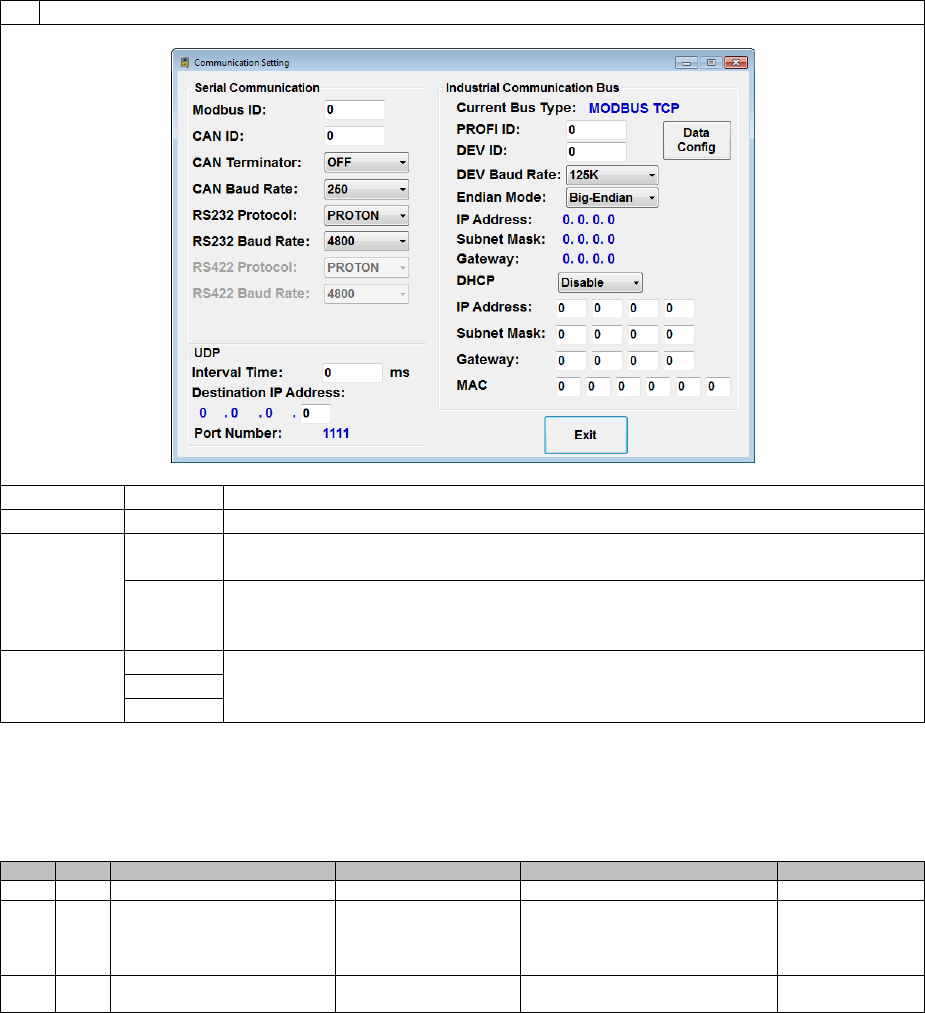
Page 59 of 126
Proton Products SL mini and SLR mini Series Speed and Length Gauges Instruction Manual - issue 1s
3
Configure the CANbus interface as required and click the “Exit” button when complete:
Label
Value
Description
CAN ID
0 ~ 255
Enter the CANbus address for the gauge.
CAN
Terminator
OFF
If the gauge is not located at the end of the CANbus, then select “OFF” to
disable the internal termination resistor.
ON
If the gauge is located at the end of the CANbus and no external termination
resistor has been installed, then select “ON” to enable the internal
termination resistor.
CAN Baud
Rate
250
Select the required CANbus baud rate (in kbps).
500
1000
Configuration via input parameters:
This interface may be configured by writing to the following input parameters:
Input parameters
DW
Bit
Comment
Unit
Range/Remark
Default
21
CAN address
1=1
0~255
14
22
CAN baud rate
0=250
1=500
2=1000
other=500
2
36
CAN terminator
1=1
0=Off
1=On
0
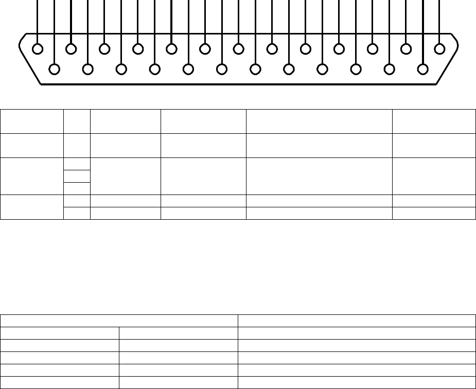
Page 60 of 126
Proton Products SL mini and SLR mini Series Speed and Length Gauges Instruction Manual - issue 1s
RS-232 COMMUNICATIONS
This RS-232 interface is fitted as standard. It operates independently of the other communications
interfaces and may be accessed at the same time as them.
If the RS-232 interface “Mode” is set to “ZM400 Printer”, then a Zebra ZM400 printer may be
connected to the port to print reel report tickets when triggered by the “End of Reel” logic input.
RS-232 interface
The RS-232 interface may be accessed through the following pins:
Connector type: DB25 female (socket)
Functional
group
Pin
Designation
Description
Notes
PC DB9 serial
port pin
Shield
S
Shield
Shield
Connect to cable and
connector shields
Shield
Power
supply and
ground
2
DGND
Power supply
and signal
ground (0V)
5
15
24
RS-232
16
RXD
RS-232 receive
3
17
TXD
RS-232 transmit
2
The above table also shows the configuration of a cable for connection to a personal computer (PC)
type DB9 serial port.
The maximum baud rate depends on the cable capacitance and length. For low-cost overall shielded
cable with total capacitance of shield to core-plus-core to core of 300pF per metre, the maximum
recommended baud rates are as follows:
Cable length range / m
Maximum Baud rate / s
0
3
115200
3
10
38400
10
20
19200
20
40
9600
40
80
4800
1
14
2
15
3
16
4
17
5
18
6
19
7
20
8
21
9
22
10
23
11
24
12
25
13

Page 61 of 126
Proton Products SL mini and SLR mini Series Speed and Length Gauges Instruction Manual - issue 1s
RS-232 Communications configuration
Configuration via the PCiS_SLmini software:
1
Click the “Comms” button on the main page:
2
When prompted, enter 65000 for the password and click the “OK” button:
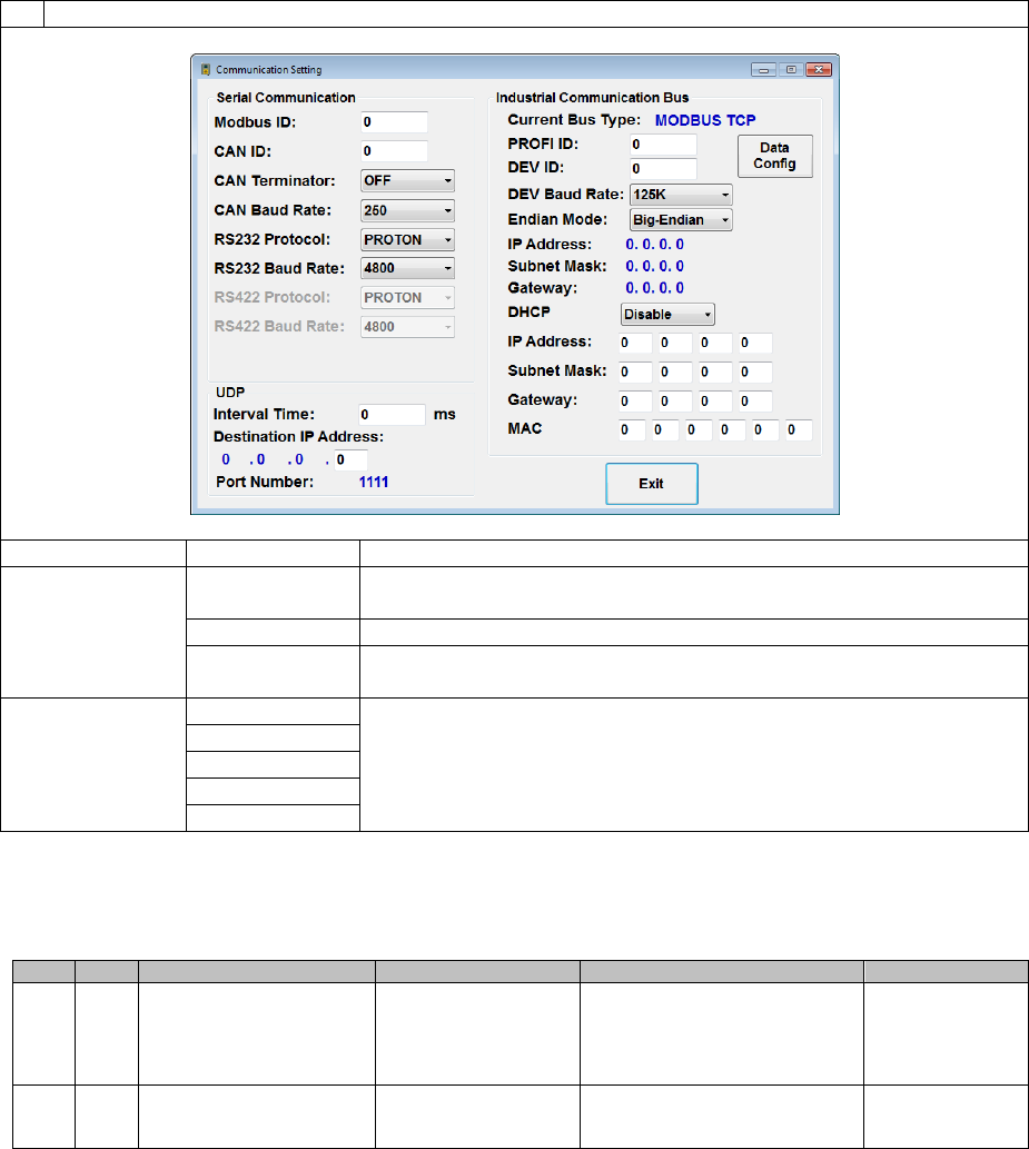
Page 62 of 126
Proton Products SL mini and SLR mini Series Speed and Length Gauges Instruction Manual - issue 1s
3
Configure the RS-232 interface as required and click the “Exit” button when complete:
Label
Value
Description
RS232 Protocol
PROTON
Select this to use the “Proton Standard Parameter Access
Protocol”.
Modbus
Select this to use the “Modbus Parameter Access Protocol”.
ZM400 Printer
Select this if connecting a ZM400 printer to the RS-232 port for
“End of Reel” ticket printing.
CAN Baud Rate
4800
Select the required RS-232 baud rate (in kbps).
9600
19200
38400
115200
Configuration via input parameters:
This interface may be configured by writing to the following input parameters:
DW
Bit
Comment
Unit
Range/Remark
Default
23
RS232 baud rate
0=4800
1=9600
2=19200
3=38400
4=115200
1
24
RS232 mode
0=Proton protocol
1=Modbus protocol
2=ZM400 Printer
1
RS-232 Printing
If the RS-232 interface “Mode” is set to “ZM400 Printer” (input parameter DW24 set to “2), then a
Zebra ZM400 printer may be connected to the port to print End of Reel report tickets when triggered
by the “End of Reel” logic input (see the “Logic Inputs” section for connection and configuration
information).
Ensure that the RS-232 baud rate (input parameter DW23) is configured to the same value as set on
the printer (9600 by default).
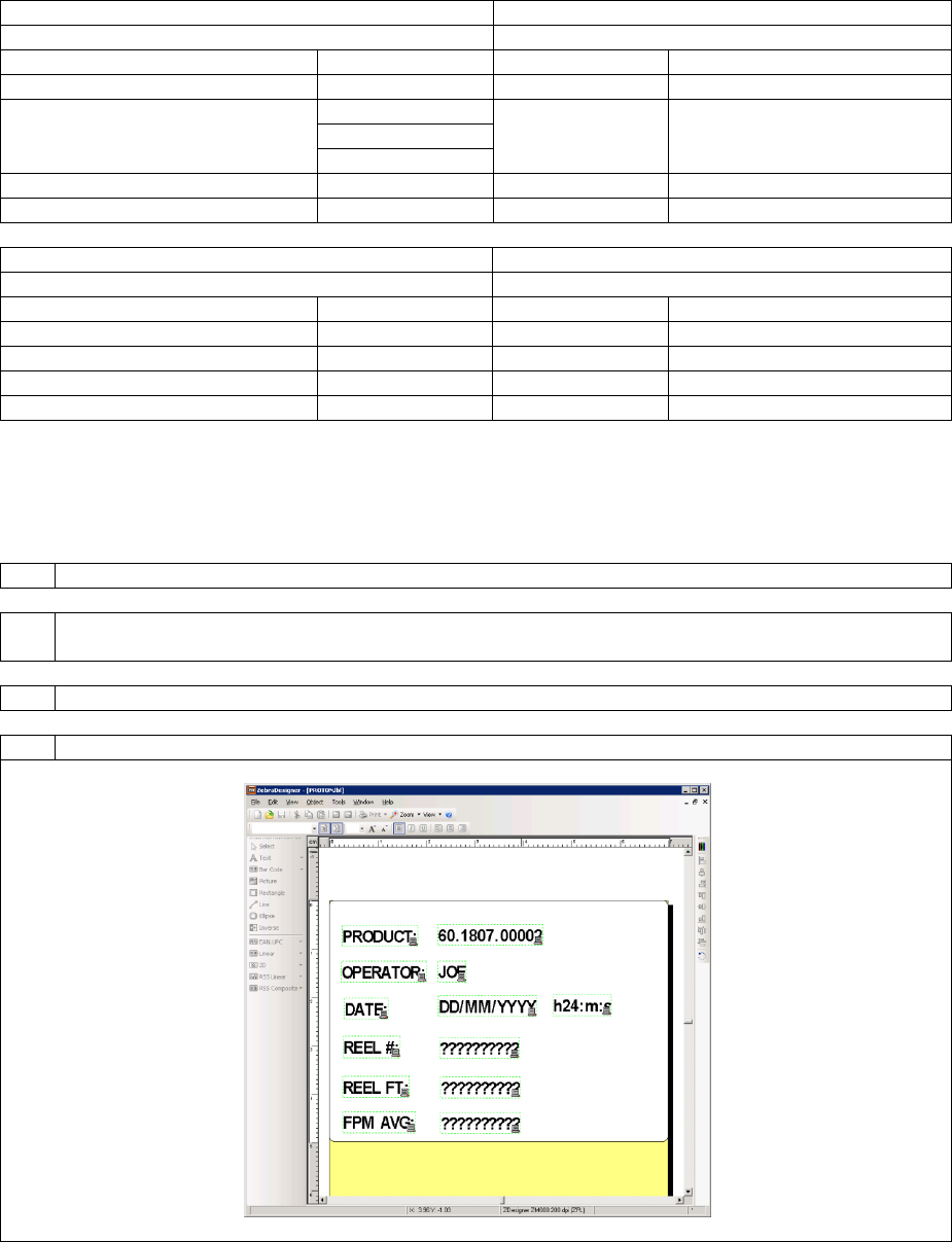
Page 63 of 126
Proton Products SL mini and SLR mini Series Speed and Length Gauges Instruction Manual - issue 1s
Zebra ZM400 Cable
The gauge may either be directly connected to the printer via the DB25F “INTERFACE” port or via the
DB9F RS-232 port on an optional PSU-BOB mini:
SL / SLR mini INTERFACE port
Zebra ZM400 RS-232 port
Required cable connector: DB25M
Required cable connector: DB9M
Designation
Pin
Pin
Designation
Shield
Shield
Shield
Shield
DGND
2
5
DGND
15
24
RXD
16
3
TXD
TXD
17
2
RXD
PSU-BOB mini RS-232 port
Zebra ZM400 RS-232 port
Required cable connector: DB9M
Required cable connector: DB9M
Designation
Pin
Pin
Designation
Shield
Shield
Shield
Shield
DGND
5
5
DGND
RXD
2
3
TXD
TXD
3
2
RXD
Zebra ZM400 Printer Configuration
The Zebra ZM400 printer must be configured with the layout of the End of Reel report ticket using the
following procedure:
1
Install the “Zebra Designer” software onto a suitable PC.
2
Install the Zebra printer drivers onto the PC (the drivers are supplied on a CD-ROM with the
Zebra ZM400 printer and may also be downloaded from www.zebra.com).
3
Connect the PC to the Zebra ZM400 printer using the USB cable supplied with the printer.
4
Run the “Zebra Designer” software and open the “PROTON.lbl” sample label layout file:
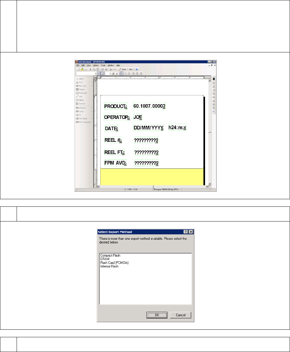
Page 64 of 126
Proton Products SL mini and SLR mini Series Speed and Length Gauges Instruction Manual - issue 1s
5
The gauge will send 3 strings in the following sequence to the Zebra ZM400 printer:
String no.1: Reel number
String no.2: Length
String no.3: Average speed
The label layout must be designed to accommodate the above 3 strings in sequence:
6
Export the “PROTON.lbl” file to the Zebra ZM400 printer by clicking “File → Export to Printer” in
the “Zebra Designer” software and then selecting “Internal Flash” and clicking the “OK” button:
7
The Zebra ZM400 printer may be triggered to print a ticket by activating the “End of Reel” logic
input on the SL / SLR mini gauge.
Page 65 of 126
Proton Products SL mini and SLR mini Series Speed and Length Gauges Instruction Manual - issue 1s
Proton standard RS232 parameter access protocol
This uses a protocol to access individual parameters or blocks of parameters and is typically used in a
production line environment where the gauge is connected to a PLC or similar device.
Notes
- The parameters are split into ‘Input’ and ‘Output’ groups, the ‘Input’ parameters can be both read
and written, and the ‘Output’ parameters can only be read
- The parameter number is the same as the word address used for Profibus data; refer to the
‘PROFIBUS Master to Gauge and RS232 Input Parameter List’ for the parameter numbers
- For ‘Input’ data: when a word is defined as bits then four hexadecimal characters are required to
form the bits 15~0; when a word is defined as a data value then only sufficient characters to define
the value in decimal format, with the decimal point where appropriate, are needed; where the data
is of double word length then only the first word address is used
- For ‘Output’ data: when a word is defined as bits then four hexadecimal characters will be sent;
when a word is defined as a data value it is converted to a decimal number with the decimal point
but without leading zeros; where a double word is used then only the first word address is used to
request the data, the data in both words is automatically converted to a single value
- If a PC keyboard is being used to enter the codes then the ‘carriage return’ plus ‘line feed’ are
replaced by the Enter key
SET THE VALUE OF AN ‘INPUT’ PARAMETER
Write Format: &
Input Parameter number
Space
Value without decimal point [0.5m = 50]
Carriage return
Line feed
REQUEST VALUE ONCE FOR ONE OR A RANGE OF ‘INPUT’ PARAMETERS
Request Format 1: (e.g.: ?2 ‘ENTER’)
?
Input Parameter number
Carriage return
Line feed
Request Format 2: (e.g.: ?2 2 ‘ENTER’)
?
Input Parameter number
Space
Length of string
Carriage return
Line feed
Page 66 of 126
Proton Products SL mini and SLR mini Series Speed and Length Gauges Instruction Manual - issue 1s
REQUEST CONTINUOUSLY REPEATING VALUES FOR ONE OR A RANGE OF
‘OUTPUT’ PARAMETERS
The repartition rate is the maximum possible and only limited by the data length and baud rate. The
parameters must be consecutive when requesting multiple parameters.
Request Format 1:
#
Parameter number
Carriage return
Line feed
Request Format 2:
#
First parameter number
Space
Number of parameters
Carriage return
Line feed
Reply Format 1:
Parameter value
Carriage return
Line feed
Reply Format 2:
First output parameter value
Carriage return
Line feed
Second output parameter value
Carriage return
Line feed
Third output parameter and so on, until the end of the range.
REQUEST VALUE ONCE FOR ONE OR A RANGE OF ‘OUTPUT’ PARAMETERS
The request and reply format is identical to the # format given below except that # is replaced by ~.
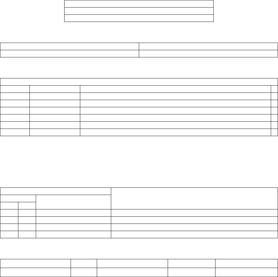
Page 67 of 126
Proton Products SL mini and SLR mini Series Speed and Length Gauges Instruction Manual - issue 1s
Modbus parameter access protocol
This protocol provides access to individual parameters or blocks of parameters and is typically used in
a production environment where the Proton Products instrument is connected to a computer, Modbus
connected PLC or similar device.
The parameters consist of 16-bit words (DW) and are divided into input and output groups:
Input parameters may be read from and written to and are used to configure the instrument.
Output parameters are read only and provide access to instrument status and measurement
data.
1 word (DW) consists of 2 bytes
1 byte consists of 8 bits
4 bits are expressed by 1 hexadecimal digit (0-9, A-F)
Proton Products instruments use the following Modbus format:
Modbus format
RTU (Remote Terminal Unit)
Error check
CRC (Cyclic Redundancy Check)
The Modbus RTU frame format is as follows:
Modbus RTU frame format
Name
Length
Function
Start
> 3.5 characters
>3.5 characters of silence
Address
1-byte
Slave (instrument) Modbus address
*
Function
1-byte
Modbus function code determines read or write operation
*
Data
Multiple bytes
Length and data dependent on function
*
CRC
2-bytes
Cyclic Redundancy Check for errors (not required for Modbus TCP)+
End
> 3.5 characters
>3.5 characters of silence
+ Please refer to Modbus Protocol Standards documentation for the CRC error check field calculation. For Modbus protocol
communications over TCP/IP networks via the Ethernet port (also known as Modbus TCP), the CRC error check field is not
required as error checking is handled by the TCP/IP protocol.
For brevity, only the fields marked * are shown in the subsequent examples.
Proton Products instruments support the following Modbus functions:
Modbus function
Instrument operation
Code
Name
Dec
Hex
03
03
Read Holding Registers
Read data from a block of consecutive input parameters.
06
06
Preset Single Register
Write data to a single input parameter.
10
16
Preset Multiple Registers
Write data to a block of consecutive input parameters.
04
04
Read Input Registers
Read data from a block of consecutive output parameters.
For Modbus protocol communications via the RS-232 serial port, the RS-232 data format is:
Number of data bits
Parity
Number of stop bits
Flow control
Default baud rate
8
None
1
None
9600 bit / s
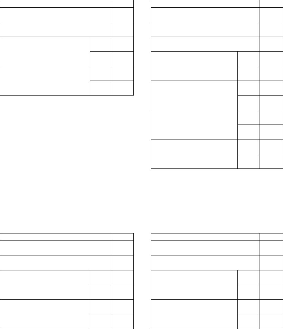
Page 68 of 126
Proton Products SL mini and SLR mini Series Speed and Length Gauges Instruction Manual - issue 1s
Read data from a block of consecutive input parameters
Use Modbus function “03” (Read Holding Registers) to read from a block of consecutive input
parameters.
Modbus query format
Hex
Modbus response format
Hex
Slave Modbus address
(Gauge Modbus address)
01
Slave Modbus address
(Gauge Modbus address)
01
Modbus function code
03
Modbus function code
03
Starting address
(Starting input parameter
address)
High
byte
00
Byte count
N = (2 × Number of points)
08
Low
byte
08
Data word 0
(corresponds to input DW8)
High
byte
01
Number of points
(Input parameter word count)
High
byte
00
Low
byte
F4
Low
byte
04
Data word 1
(corresponds to input DW9)
High
byte
01
Low
byte
F4
Data word 2
(corresponds to input DW10)
High
byte
01
Low
byte
F4
Data word [(N/2) – 1] = 3
(corresponds to input DW11)
High
byte
01
Low
byte
F4
The response contains the input parameter values requested in the query; its length is dependent on
the number of input parameters requested.
Write data to a single input parameter
Use Modbus function “06” (Preset Single Register) to read from a block of consecutive input
parameters.
Modbus query format
Hex
Modbus response format
Hex
Slave Modbus address
(Gauge Modbus address)
01
Slave Modbus address
(Gauge Modbus address)
01
Modbus function code
06
Modbus function code
06
Register address
(Input parameter address)
High
byte
00
Register address
(Input parameter address)
High
byte
00
Low
byte
06
Low
byte
06
Preset data
(Input parameter value)
High
byte
03
Preset data
(Input parameter value)
High
byte
03
Low
byte
E8
Low
byte
E8
The response is an echo of the query.

Page 69 of 126
Proton Products SL mini and SLR mini Series Speed and Length Gauges Instruction Manual - issue 1s
Write data to a block of consecutive input parameters
Use Modbus function “16 (10 Hex)” (Preset Multiple Registers) to write to a block of consecutive input
parameters.
Modbus query format
Hex
Modbus response format
Hex
Slave Modbus address
(Gauge Modbus address)
01
Slave Modbus address
(Gauge Modbus address)
01
Modbus function code
10
Modbus function code
10
Starting address
(Starting input parameter
address)
High
byte
00
Starting address
(Starting input parameter
address)
High
byte
00
Low
byte
01
Low
byte
01
Number of registers
(Input parameter word count)
High
byte
00
Number of registers
(Input parameter word count)
High
byte
00
Low
byte
03
Low
byte
03
Byte count
N = (2 × Number of registers)
06
Data word 0
(corresponds to input DW1)
High
byte
1F
Low
byte
40
Data word 1
(corresponds to input DW2)
High
byte
1F
Low
byte
40
Data word [(N/2) – 1] = 2
(corresponds to input DW3)
High
byte
1F
Low
byte
40
The response contains the starting input parameter address and the count of input parameter words
written.

Page 70 of 126
Proton Products SL mini and SLR mini Series Speed and Length Gauges Instruction Manual - issue 1s
Read data from a block of consecutive output parameters
Use Modbus function “04” (Read Input Registers) to write to a block of consecutive input parameters.
Modbus query format
Hex
Modbus response format
Hex
Slave Modbus address
(Gauge Modbus address)
01
Slave Modbus address
(Gauge Modbus address)
01
Modbus function code
04
Modbus function code
04
Starting address
(Starting output parameter
address)
High
byte
00
Byte count
N = (2 × Number of points)
06
Low
byte
02
Data word 0
(corresponds to output DW2)
High
byte
07
Number of points
(Output parameter word
count)
High
byte
00
Low
byte
D0
Low
byte
03
Data word 1
(corresponds to output DW3)
High
byte
05
Low
byte
DC
Data word 2
[(N/2) – 1]
(corresponds to output DW4)
High
byte
09
Low
byte
C4
The response contains the output parameter values requested in the query; its length is dependent on
the number of output parameters requested.
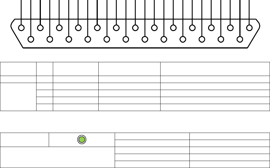
Page 71 of 126
Proton Products SL mini and SLR mini Series Speed and Length Gauges Instruction Manual - issue 1s
ETHERNET COMMUNICATIONS
This Ethernet interface is fitted as standard. It operates independently of the other communications
interfaces and may be accessed at the same time as them.
If an optional industrial bus interface (Ethernet/IP, PROFIBUS or DeviceNET) has been installed in
the gauge, then the Ethernet interface is substituted by the industrial bus interface.
Ethernet interface
The Ethernet interface may be accessed through the following pins:
Connector type: DB25 female (socket)
Functional
group
Pin
Designation
Description
Notes
Shield
S
Shield
Shield
Connect to cable and plug shields
Ethernet
22
IBUS1
TX+
10
IBUS2
TX-
23
IBUS3
RX+
11
IBUS4
RX-
Ethernet LED indicator
EIP
LED status
Indication
Continuous green
Online and connected
Ethernet communications
Flashing green
Online but not connected
Continuous red
Critical link failure
Flashing red
Connection timeout
1
14
2
15
3
16
4
17
5
18
6
19
7
20
8
21
9
22
10
23
11
24
12
25
13

Page 72 of 126
Proton Products SL mini and SLR mini Series Speed and Length Gauges Instruction Manual - issue 1s
Ethernet configuration
Configuration via the PCiS_SLmini software:
1
Click the “Comms” button on the main page:
2
When prompted, enter 65000 for the password and click the “OK” button:
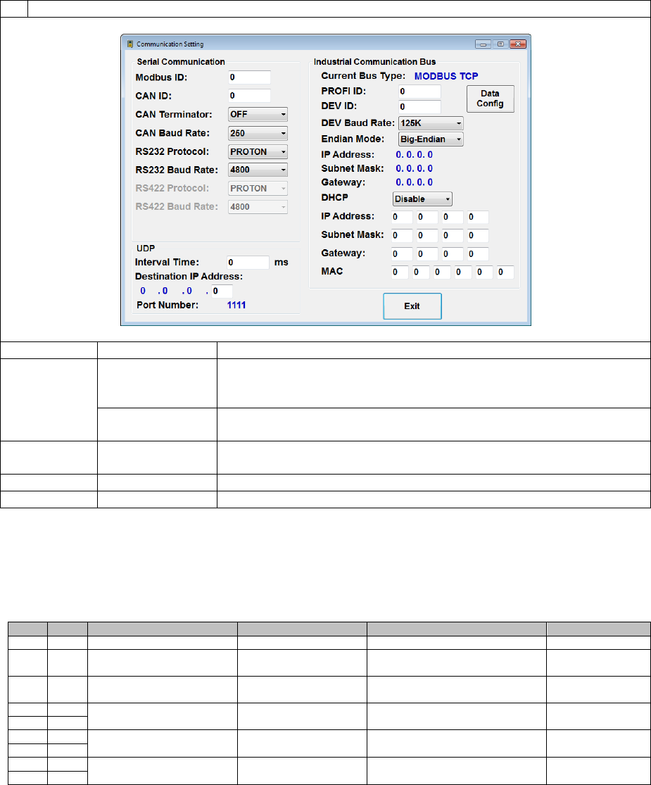
Page 73 of 126
Proton Products SL mini and SLR mini Series Speed and Length Gauges Instruction Manual - issue 1s
3
Configure the Ethernet interface as required and click the “Exit” button when complete:
Label
Value
Description
DHCP
Enable
Select this option to enable the gauge to automatically acquire its
IP Address, Subnet Mask and Gateway from a DHCP server on
the network.
Disable
Select this option to manually configure the gauge IP Address,
Subnet Mask and Gateway in the fields below:
IP Address
[192.168.1.110]
Enter the IP address assigned to the gauge in dotted decimal
format.
Subnet Mask
[255.255.255.0]
Enter the subnet mask for the network in dotted decimal format.
Gateway
[192.168.1.1]
Enter the gateway for the network in dotted decimal format.
* [ ] indicates factory-default values.
Configuration via input parameters:
This interface may be configured by writing to the following input parameters:
Input parameters
DW
Bit
Comment
Unit
Range/Remark
Default
27
Modbus address
1=1
0~255
1
28
EtherNet protocol
0=Modbus protocol
1=EIP protocol
0
29
DHCP
0=Disabled
1=Enabled
0
30
IP address
x.x.x.x
C0A8016E
(192.168.1.110)
31
32
Subnet mask
x.x.x.x
FFFF0000
(255.255.255.0)
33
34
Gateway
x.x.x.x
C0A80001
(192.168.1.1)
35

Page 74 of 126
Proton Products SL mini and SLR mini Series Speed and Length Gauges Instruction Manual - issue 1s
Input Parameter Write Disable
The gauge may be configured to write-disable specific input parameters when a page of input
parameters is written via the optional DeviceNET, PROFIBUS, PROFINET or EtherNet/IP
communications interface.
Input parameters may be write-disabled for the following purposes:
To simplify setup: all unused input parameters may be write-disabled to simplify the
composition of the written data page.
To avoid unintended modification of specific parameters: input parameters which must
NOT be changed via the optional communication interface (e.g. input parameters which
determine the operating mode of the gauge) may be write-disabled.
Input parameter write-disable does NOT apply to the CANbus, RS-232 or Ethernet interfaces.
1
Click the “Comms” button on the main page:
2
When prompted, enter 65000 for the password and click the “OK” button:
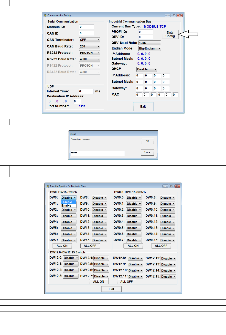
Page 75 of 126
Proton Products SL mini and SLR mini Series Speed and Length Gauges Instruction Manual - issue 1s
3
Click the “Data Config” button to access the “Data Configuration for Master to Slave” page:
4
When prompted, enter 65065 for the password and click the “OK” button:
5
Enable or disable writing of input parameter DW words or bits via the optional DeviceNET,
PROFIBUS, PROFINET or EtherNet/IP communications interfaces:
Label
Description
Enable
Select to enable writing of the specific input parameter DW word or bit.
Disable
Select to disable writing of the specific input parameter DW word or bit.
ALL ON
Click to enable writing of all associated input parameter DW words.
ALL OFF
Click to disable writing of all associated input parameter DW words.
Exit
Click to exit this page and return to the “Communication Setting” page.
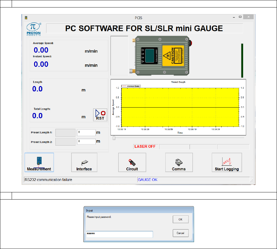
Page 76 of 126
Proton Products SL mini and SLR mini Series Speed and Length Gauges Instruction Manual - issue 1s
UDP Protocol
The gauge may be configured to continuously send data by UDP-protocol (at a user-configured rate)
to a server on the same network.
Configuration via the PCiS_SLmini software:
1
Click the “Comms” button on the main page:
2
When prompted, enter 65000 for the password and click the “OK” button:
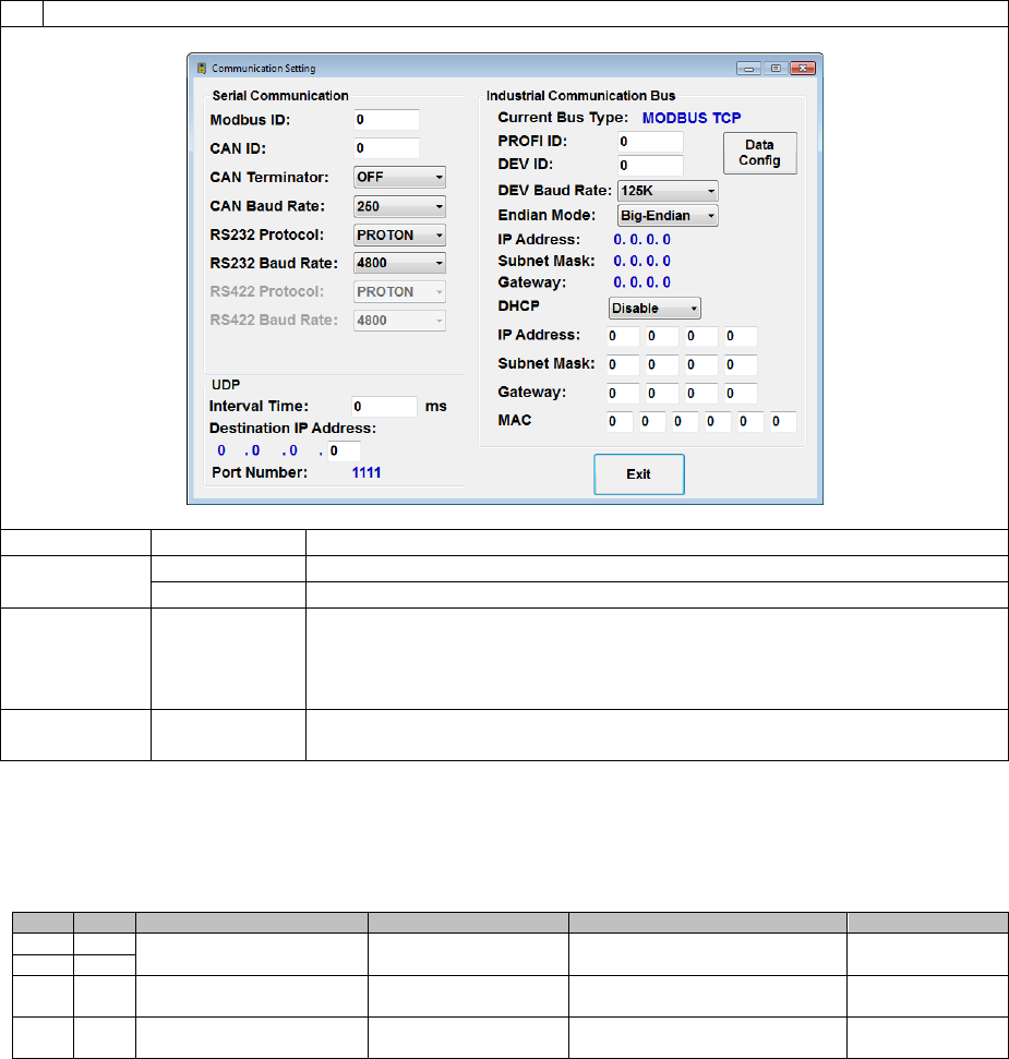
Page 77 of 126
Proton Products SL mini and SLR mini Series Speed and Length Gauges Instruction Manual - issue 1s
3
Configure the Ethernet interface as required and click the “Exit” button when complete:
Label
Value
Description
Interval Time
0
Disable UDP data output.
1 ~ 5000 ms
Output UDP data at this interval time.
Destination
IP Address
x.x.x.x
Destination server IP address to which UDP data is sent (only the final
octet is configurable, the first 3 octets are the same as the gauge IP
Address, hence the destination server must be on the same network
as the gauge).
Port Number
1111
Destination server port to which UDP data is sent (fixed at 1111, not
end-user configurable).
Configuration via input parameters:
The UDP data output function may be configured by writing to the following input parameters:
Input parameters
DW
Bit
Comment
Unit
Range/Remark
Default
30
IP address
x.x.x.x
C0A80001
(192.168.0.1)
31
41
UDP data output interval
time
1=1ms
1~5000
0=Disable UDP output
0
48
UDP destination IP
address (last octet only)
Note: the UDP destination port
number is fixed at 1111
2
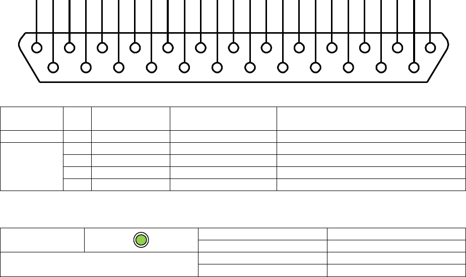
Page 78 of 126
Proton Products SL mini and SLR mini Series Speed and Length Gauges Instruction Manual - issue 1s
OPTIONAL COMMUNICATIONS INTERFACES
PROFIBUS COMMUNICATIONS
The PROFIBUS interface is an optional extra that must be ordered for installation during
manufacture; it cannot be retrofitted to the gauge.
This communications interface operates independently of the other communications interfaces and
may be used at the same time as them.
PROFIBUS interface
The PROFIBUS interface may be accessed through the following pins:
Connector type: DB25 female (socket)
Functional
group
Pin
Designation
Description
Notes
Shield
S
Shield
Shield
Connect to cable and plug shields
PROFIBUS
Industrial
bus
22
IBUS1
+5V
10
IBUS2
GND
23
IBUS3
A
11
IBUS4
B
PROFIBUS LED indicator
i-BUS
LED status
Indication
Continuous green
Online
PROFIBUS communications
Continuous red
Communication error
Extinguished
No communication
1
14
2
15
3
16
4
17
5
18
6
19
7
20
8
21
9
22
10
23
11
24
12
25
13

Page 79 of 126
Proton Products SL mini and SLR mini Series Speed and Length Gauges Instruction Manual - issue 1s
PROFIBUS configuration
The gauge head is configured as a PROFIBUS slave.
Configuration via the PCiS_SLmini software:
1
Click the “Comms” button on the main page:
2
When prompted, enter 65000 for the password and click the “OK” button:
3
Configure the PROFIBUS interface as required and click the “Exit” button when complete:
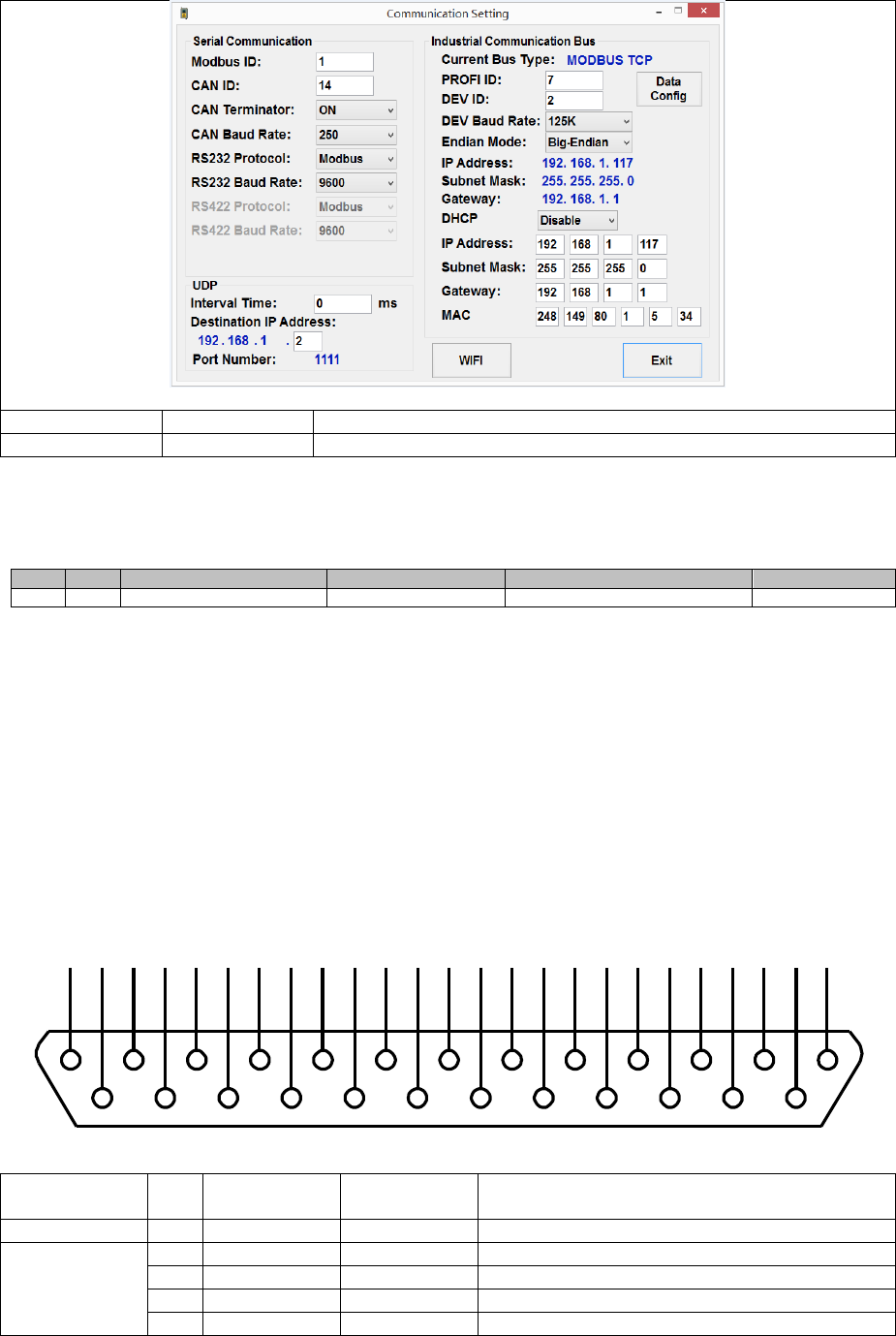
Page 80 of 126
Proton Products SL mini and SLR mini Series Speed and Length Gauges Instruction Manual - issue 1s
Label
Value
Description
PROFI ID
0 ~ 125
Enter the PROFIBUS ID (address) assigned to the gauge.
Configuration via input parameters:
This interface may be configured by writing to the following input parameters:
Input parameters:
DW
Bit
Comment
Unit
Range/Remark
Default
20
Profibus address
1=1
0~125
7
ETHERNET / IP OR PROFINET COMMUNICATIONS
The EtherNet / IP or PROFINET interface is an optional extra that must be ordered for
installation during manufacture; it cannot be retrofitted to the gauge.
The Ethernet/IP interface is compatible with PLCs fitted with an Ethernet/IP interface that supports the
CIP (Common Industrial Protocol).
This communications interface operates independently of the other communications interfaces and
may be used at the same time as them.
EtherNet / IP or PROFINET interface
The EtherNet / IP or PROFINET interface may be accessed through the following pins:
Connector type: DB25 female (socket)
Functional
group
Pin
Designation
Description
Notes
Shield
S
Shield
Shield
Connect to cable and plug shields
Ethernet/IP or
PROFINET
Industrial bus
22
IBUS1
TX+
10
IBUS2
TX-
23
IBUS3
RX+
11
IBUS4
RX-
1
14
2
15
3
16
4
17
5
18
6
19
7
20
8
21
9
22
10
23
11
24
12
25
13
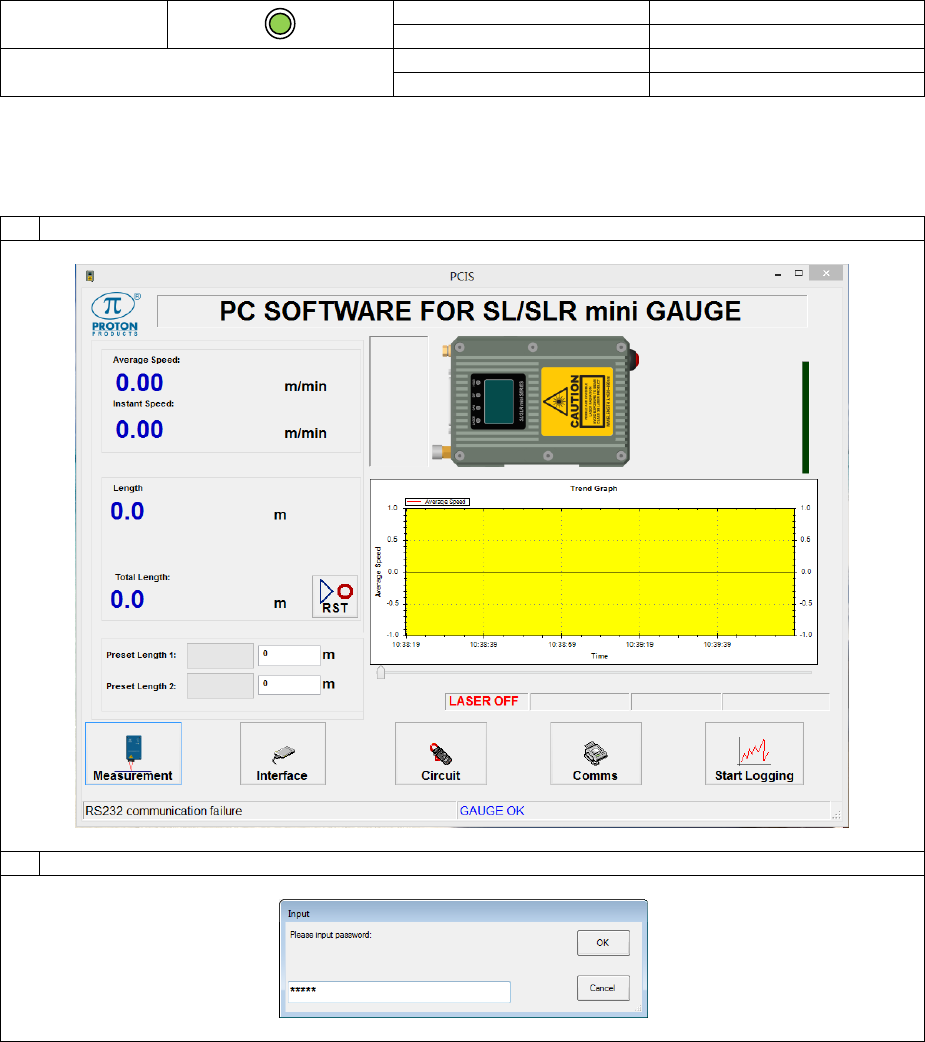
Page 81 of 126
Proton Products SL mini and SLR mini Series Speed and Length Gauges Instruction Manual - issue 1s
EtherNet / IP or PROFINET LED indicator
i-BUS
LED status
Indication
Continuous green
Online
EtherNet / IP or PROFINET
communications
Continuous red
Communication error
Extinguished
No communication
EtherNet / IP or PROFINET configuration
Configuration via the PCiS_SLmini software:
1
Click the “Comms” button on the main page:
2
When prompted, enter 65000 for the password and click the “OK” button:
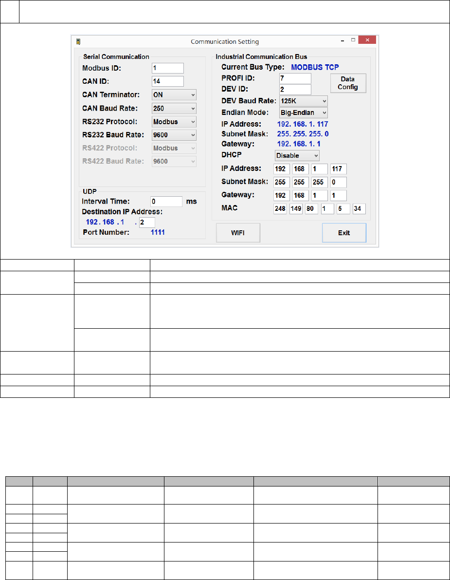
Page 82 of 126
Proton Products SL mini and SLR mini Series Speed and Length Gauges Instruction Manual - issue 1s
3
Configure the EtherNet / IP or PROFINET interface as required and click the “Exit” button when
complete:
Label
Value*
Description
Endian Mode
[Big-Endian]
Select for Big-Endian data format.
Little-Endian
Select for Little-Endian data format.
DHCP
Enable
Select this option to enable the gauge to automatically acquire its
IP Address, Subnet Mask and Gateway from a DHCP server on
the network.
Disable
Select this option to manually configure the gauge IP Address,
Subnet Mask and Gateway in the fields below:
IP Address
192.168.1.110
Enter the IP address assigned to the gauge in dotted decimal
format.
Subnet Mask
255.255.0.0
Enter the subnet mask for the network in dotted decimal format.
Gateway
192.168.1.1
Enter the gateway for the network in dotted decimal format.
* [ ] indicates factory-default value.
Configuration via input parameters:
This interface may be configured by writing to the following input parameters:
Input parameters
DW
Bit
Comment
Unit
Range/Remark
Default
29
DHCP
0=Disabled
1=Enabled
0
30
IP address
x.x.x.x
C0A8016E
(192.168.1.110)
31
32
Subnet mask
x.x.x.x
FFFF0000
(255.255.0.0)
33
34
Gateway
x.x.x.x
C0A80001
(192.168.1.1)
35
49
Endianess
1=Little endian
0=Big endian
0
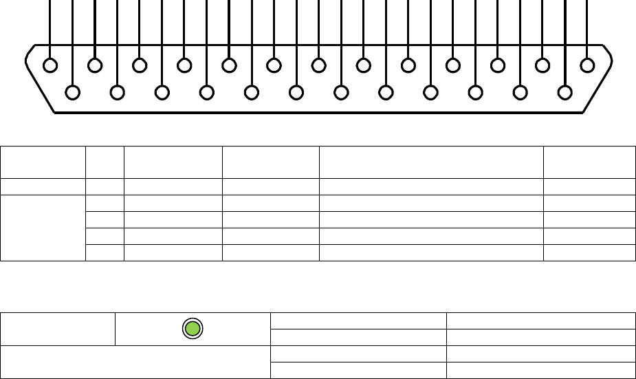
Page 83 of 126
Proton Products SL mini and SLR mini Series Speed and Length Gauges Instruction Manual - issue 1s
DEVICENET COMMUNICATIONS
The DeviceNet interface is an optional extra that must be ordered for installation during
manufacture; it cannot be retrofitted to the gauge.
This communications interface operates independently of the other communications interfaces and
may be used at the same time as them.
DeviceNet interface
The DeviceNet interface may be accessed through the following pins:
Connector type: DB25 female (socket)
Functional
group
Pin
Designation
Description
Notes
DeviceNet
wire colour
Shield
S
Shield
Shield
Connect to cable and plug shields
Bare wire
DeviceNET
Industrial
bus
22
IBUS1
V+
Red
10
IBUS2
V-
Black
23
IBUS3
CANH
White
11
IBUS4
CANL
Blue
DeviceNet LED indicator
i-BUS
LED status
Indication
Continuous green
Online
DeviceNet communications
Continuous red
Communication error
Extinguished
No communication
1
14
2
15
3
16
4
17
5
18
6
19
7
20
8
21
9
22
10
23
11
24
12
25
13

Page 84 of 126
Proton Products SL mini and SLR mini Series Speed and Length Gauges Instruction Manual - issue 1s
DeviceNet configuration
Configuration via the PCiS_SLmini software:
1
Click the “Comms” button on the main page:
2
When prompted, enter 65000 for the password and click the “OK” button:
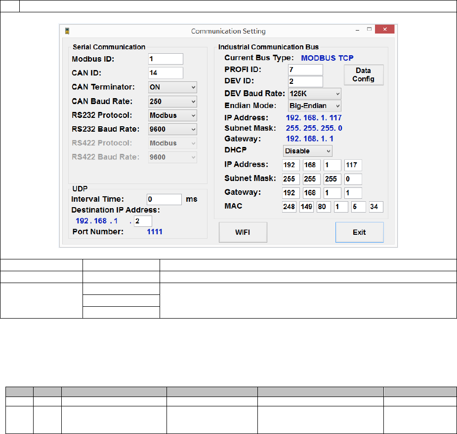
Page 85 of 126
Proton Products SL mini and SLR mini Series Speed and Length Gauges Instruction Manual - issue 1s
3
Configure the DeviceNet interface as required and click the “Exit” button when complete:
Label
Value
Description
DEV ID
0 ~ 125
Enter the DeviceNet ID (address) assigned to the gauge.
DEV Baud Rate
125K
Enter the DeviceNet baud rate.
250K
500K
Configuration via input parameters:
This interface may be configured by writing to the following input parameters:
Input parameters:
DW
Bit
Comment
Unit
Range/Remark
Default
46
DeviceNet address
0~63
7
47
DeviceNet baud rate
0=125K
1=250K
2=500K
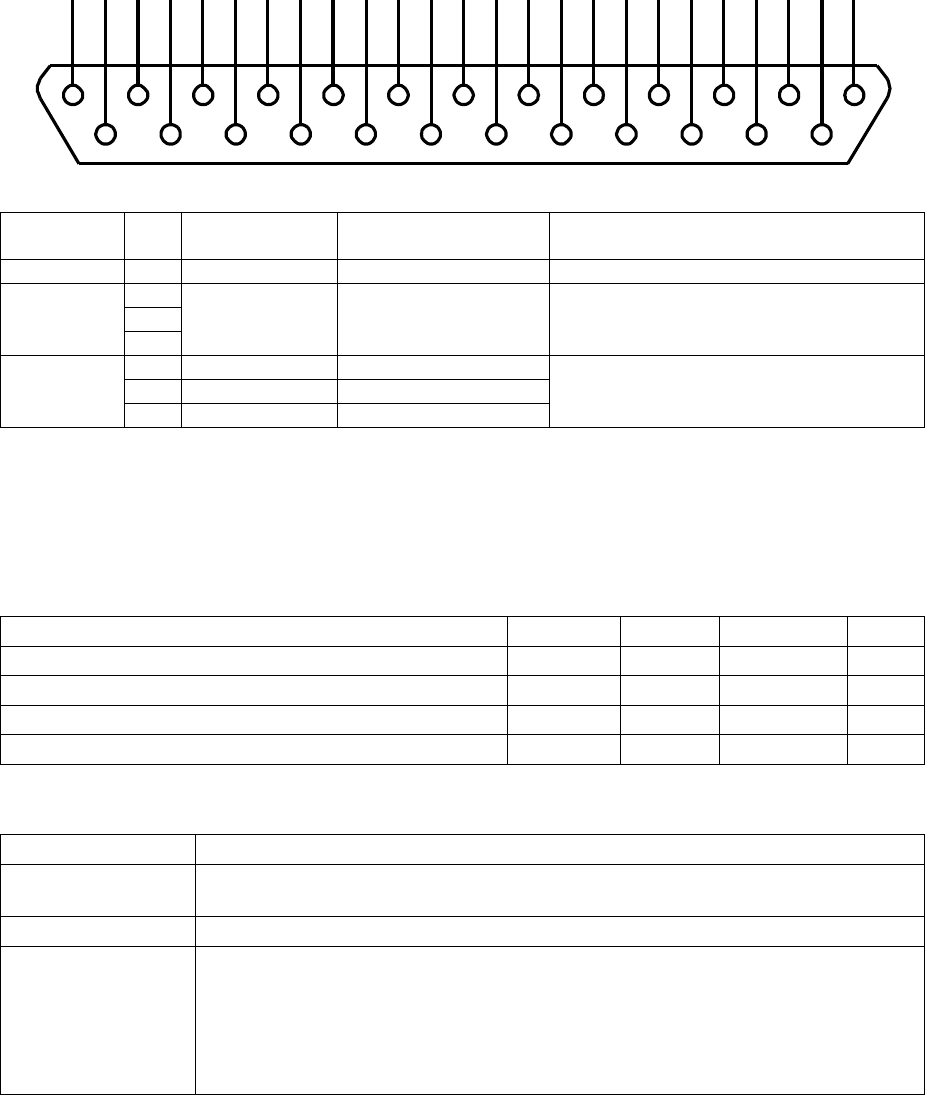
Page 86 of 126
Proton Products SL mini and SLR mini Series Speed and Length Gauges Instruction Manual - issue 1s
STANDARD ELECTRICAL INTERFACES
LOGIC INPUTS
Logic inputs connection
Two logic inputs are fitted as standard and may be accessed through the following pins:
Connector type: DB25 female (socket)
Functional
group
Pin
Designation
Description
Notes
Shield
S
Shield
Shield
Connect to cable and plug shields
Power
supply and
ground
2
DGND
Power supply and
signal ground (0V)
15
24
Logic
inputs
3
LIN1
Logic input 1
Low state (logic 0) voltage < +3V
High state (logic 1) voltage > +10.5V
Maximum input voltage ±30V
4
LIN2
Logic input 2
5
LIN3
Logic input 3
Logic inputs electrical specification
Logic inputs are NOT isolated from earth.
Inputs are internally pulled up to +15V via 8.2kΩ resistors; unconnected inputs default to the high
state.
Inputs will source a minimum current of 3mA when externally pulled down to the low state.
Specification
Minimum
Typical
Maximum
Units
Low state (logic 0) input voltage
3
V
High state (logic 1) input voltage
10.5
V
Absolute input voltage
-30
30
V
Low state source current
3
mA
Logic inputs can be connected to different types of signal sources as follows:
Signal source
Connection method
Mechanical or solid
state relay contact
Connect between logic input and DGND.
Pull-down
Connect the pull-down signal to the logic input and ground to DGND.
Pull-up
Connect an 820Ω resistor between the logic input and DGND to pull the
input down to 2.5V.
Connect the pull-up signal source to the logic input and ground to DGND.
For 24V signals (such as from a PLC), the power dissipation in the 820Ω
resistor can be reduced by connecting another 820Ω in series between the
pull-up signal source and logic input.
1
14
2
15
3
16
4
17
5
18
6
19
7
20
8
21
9
22
10
23
11
24
12
25
13
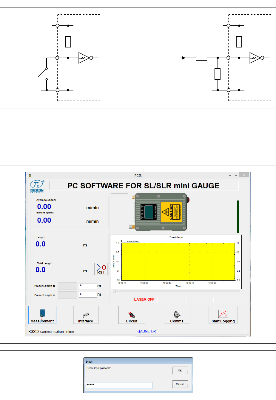
Page 87 of 126
Proton Products SL mini and SLR mini Series Speed and Length Gauges Instruction Manual - issue 1s
Pull-down
Pull-up
Logic inputs configuration
Each individual logic input can be independently configured for both active state polarity and function.
Configuration via the PCiS_SLmini software:
1
Click the “Interface” button on the main page:
2
When prompted, enter 64000 for the password and click the “OK” button:
+15V
DGND
5.1kΩ
+15V
DGND
5.1kΩ
820Ω
820Ω
From PLC
Active High
Logic Output
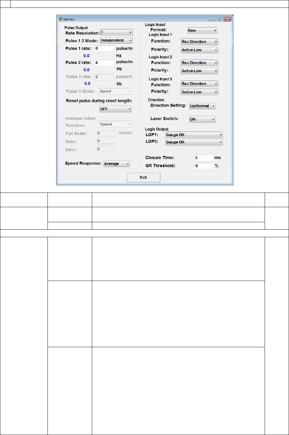
Page 88 of 126
Proton Products SL mini and SLR mini Series Speed and Length Gauges Instruction Manual - issue 1s
3
Configure the logic input interface as required and click the “Exit” button when complete:
Label
Value*
Description
Input
DW
Format
New
Select “New” (factory-default setting) to configure the logic
inputs as below.
12.15
Old
Select “Old” for backward compatibility with Proton Products
Logic Input 1
Function
Rev
Direction
Activate to reverse the length counting direction.
For SL gauges, when this input is activated (for example by
a direction wheel) the gauge will decrement length.
See the “Measurement Direction” section for
information on how this logic input affects length
accumulation.
12
Length Hold
Activate to hold the length measurement by forcing the
speed measurement to zero.
The lengths read from output parameters DW6-7
and DW12-13 will be held at their values at the
instant of activation.
The speeds read from output parameters DW2-3
and DW4-5 will be forced to zero.
The frequency of the pulse outputs is also forced to
zero.
Display Hold
Activate to hold the displayed speed and length
measurements at the instant of activation for ease of
reading.
The gauge internally continues to measure speed
and length and the display will revert to these live
values when this logic input returns to inactive.
The lengths read from output parameters DW6-7
and DW12-13 and speeds read from output
parameters DW2-3 and DW4-5 will continue to
update even with “Display Hold” active.
The pulse outputs are NOT affected by this function
and will continue to correspond to the object speed.
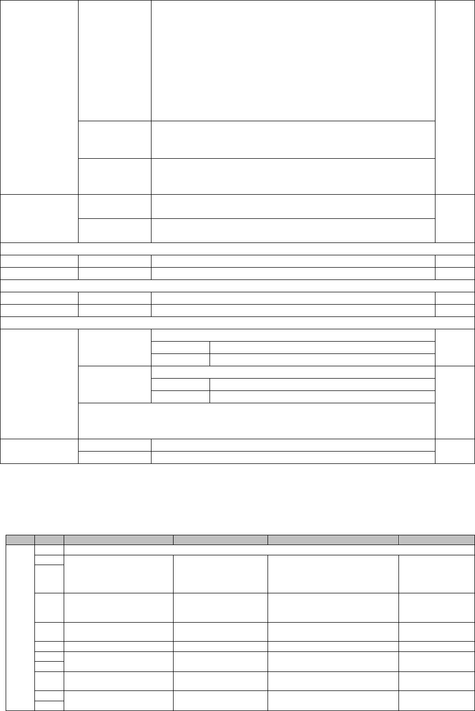
Page 89 of 126
Proton Products SL mini and SLR mini Series Speed and Length Gauges Instruction Manual - issue 1s
Speed Hold
Activate to hold the speed measurement at its value at the
instant of activation.
The length reading will accumulate at the held
speed (including lengths read from output
parameters DW6-7 and DW12-13).
The speeds read from output parameters DW2-3
and DW4-5 will be held at their values at the instant
of activation.
The frequency of the pulse outputs is held at the
corresponding speed value.
Reset
Activate momentarily to reset the length to zero.
Activate for longer than 5 seconds to also reset the
“Reel Number” to zero.
End of Reel
Activate to increment the “Reel Number” and trigger printing
of the End of Reel report on a Zebra ZM400 printer
attached to the RS-232 port.
Polarity
Active Low
Pulling the logic input low (logic 0) activates the configured
function.
12
Active High
Pulling the logic input high (logic 1) activates the configured
function.
Logic Input 2
Function
As per “Logic Input 1” above.
12
Polarity
As per “Logic Input 1” above.
12
Logic Input 3
Function
As per “Logic Input 1” above.
12
Polarity
As per “Logic Input 1” above.
12
Direction
Setting
[Up/Normal]
Select this for normal length accumulation.
SL mini
Object motion increments length.
SLR mini
Standard direction increments length.
Down/Invert
Select this for reverse length accumulation.
12.12
SL mini
Object motion decrements the length.
SLR mini
Standard direction decrements length.
Note: if any of the logic inputs are configured for the “Rev Direction”
function, then this “Directing Setting” is overridden by the logic input and
has no effect.
Laser Switch
[ON]
Select to switch on the laser diode.
13
OFF
Select to switch off the laser diode.
* factory-default values are shown in enclosed in [ ].
Configuration by input parameters:
This interface may be configured by writing to the following input parameters:
Input parameters
DW
Bit
Comment
Unit
Range/Remark
Default
12
Logic input (old format: compatible with old SL gauge;DW12.15=0)
0
Logic input 1 function
0=Direction
1=Length hold
2=Display hold
3=Speed hold
1
1
2
Direction setting (available
only when no logic input
for direction)
0=Count up
1=Count down
0
3
Logic input 1 polarity
0=Active low
1=Active high
0
4~7
Not used
0
8
Logic input 2 function
0=Reset input
1=Length hold
0
9
10
Logic input 2 polarity
0=Active low
1=Active high
0
11
Logic input 3 function
0=Direction
1=Length hold
1
12

Page 90 of 126
Proton Products SL mini and SLR mini Series Speed and Length Gauges Instruction Manual - issue 1s
DW
Bit
Comment
Unit
Range/Remark
Default
13
2=Display hold
3=Speed hold
4=Reset
14
Logic input 3 polarity
0=Active low
1=Active high
0
15
Must be 0
0=Old format logic inputs
0
12
Logic input(new format;DW12.15=1)
0
Logic input 1 function
0=direction (count down)
1=Length hold
2=Display hold
3=Speed hold
4=Reset
5=End of Reel
0
1
2
3
Logic input 1 polarity
0=Active low
1=Active high
0
4
Logic input 2 function
0=direction (count down)
1=Length hold
2=Display hold
3=Speed hold
4=Reset
5=End of Reel
1
5
6
7
Logic input 2 polarity
0=Active low
1=Active high
0
8
Logic input 3 function
0=direction (count down)
1=Length hold
2=Display hold
3=Speed hold
4=Reset
5=End of Reel
4
9
10
11
Logic input 3 polarity
0=Active low
1=Active high
0
12
Direction setting (available
only when no logic input
for direction)
0=Count up
1=Count down
0
13~
14
Not used
15
Must be 1
1=New format logic inputs
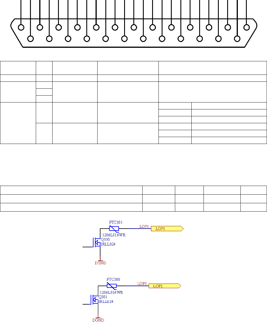
Page 91 of 126
Proton Products SL mini and SLR mini Series Speed and Length Gauges Instruction Manual - issue 1s
LOGIC OUTPUTS
Logic outputs connection
Two outputs are fitted as standard and may be accessed through the following pins:
Connector type: DB25 female (socket)
Functional
group
Pin
Designation
Description
Notes
Shield
S
Shield
Shield
Connect to cable and plug shields
Power
supply and
ground
2
DGND
Power supply and
signal ground (0V)
Floating (inactive) or pull-down to
DGND (active)
15
24
Logic
outputs
6
LOP1
Logic output 1
State
Output
Inactive
Floating
Active
Pulled down to DGND
7
LOP2
Logic output 2
State
Output
Inactive
Floating
Active
Pulled down to DGND
Logic outputs electrical specifications
The logic outputs must NOT be used to directly drive high-current or inductive loads.
It is recommended that the logic outputs are used to drive opto-isolated solid-state relays.
Specification
Minimum
Typical
Maximum
Units
Logic output to DGND voltage
+25
VDC
Current
0.1
A
1
14
2
15
3
16
4
17
5
18
6
19
7
20
8
21
9
22
10
23
11
24
12
25
13

Page 92 of 126
Proton Products SL mini and SLR mini Series Speed and Length Gauges Instruction Manual - issue 1s
Logic outputs configuration
Each individual logic output can be independently configured to pull-down to DGND upon any one of
the following conditions:
Configuration via the PCiS_SLmini software:
1
Click the “Interface” button on the main page:
2
When prompted, enter 64000 for the password and click the “OK” button:
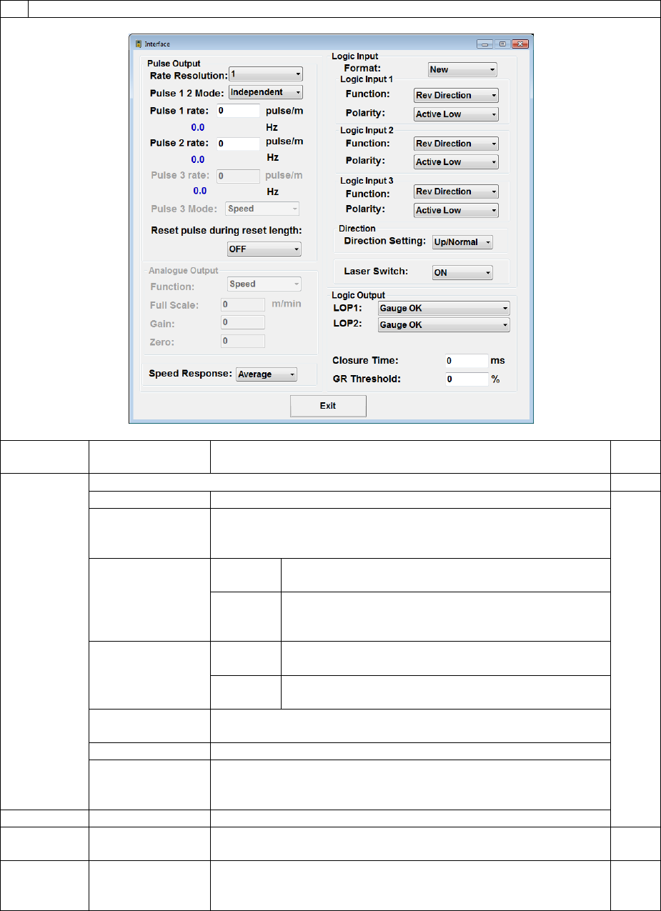
Page 93 of 126
Proton Products SL mini and SLR mini Series Speed and Length Gauges Instruction Manual - issue 1s
3
Configure the logic output interface as required and click the “Exit” button when complete:
Label
Value*
Description
Input
DW
LOP1
Select the condition to pull-down the logic output:
Gauge OK
There are no errors in the operation of the gauge.
16
Gauge
Measuring
Speed
The gauge is measuring speed.
Preset Length 1
/ Batch Length
Normal
mode
The measured length exceeds “Preset Length 1”.
Batch
mode
The measured length equals the “Batch Length”
(the logic output is pulled down momentarily for
the duration of the “Closure Time” setting below).
Preset Length 2
/ Batch Number
Normal
mode
The measured length exceeds “Preset Length 2”.
Batch
mode
The number of measured batch lengths is equal
to or greater than the “Batch Number”.
Good Reading
The “Good Readings” percentage exceeds the “GR
Threshold” set below.
Object Detected
An object has been detected by the gauge.
Gauge Too Hot
The gauge temperature has exceeded its safe operating limit
of 45°C (this output may be used to activate external cooling
systems).
LOP2
As per LOP1
As per LOP1
Closure
Time
10 ~ [500] ~
5000 ms
Set the minimum pull-down time (in milliseconds) for any
logic outputs configured for the “Batch Length” function.
4
GR
Threshold
0 ~ [60] ~ 100 %
Set the threshold above which the “Good Readings”
percentage will trigger pull-down of any logic output
configured to the “Good Reading” condition.
18
* factory-default values are shown in enclosed in [ ].

Page 94 of 126
Proton Products SL mini and SLR mini Series Speed and Length Gauges Instruction Manual - issue 1s
Configuration by input parameters:
This interface may be configured by writing to the following input parameters:
Input parameters
DW
Bit
Comment
Unit
Range/Remark
Default
4
Batch mode LOP closure time
1=10ms
1~500 (10ms~5s)
50
16
Logic output function
0~3
LOP1 function
0=Gauge OK
1=Gauge measuring speed
2=Preset length 1 / Batch length
3=Preset length 2 / Batch number
4=Good reading
5=Object detected
6=Gauge too hot
0
4~7
LOP2 function
2
8~15
Not used
3
18
Good Reading threshold
1=1%
60%
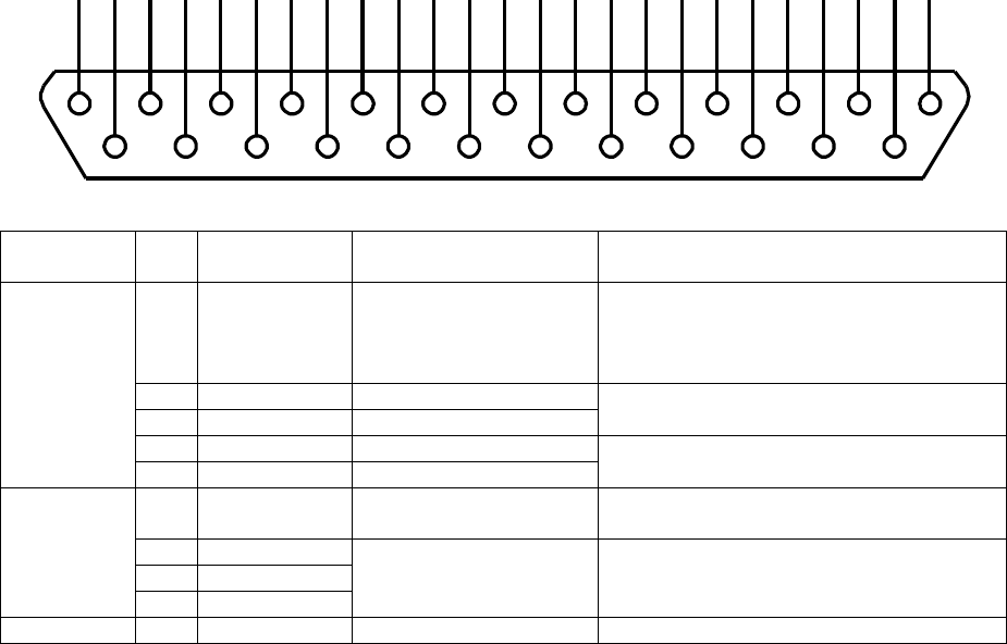
Page 95 of 126
Proton Products SL mini and SLR mini Series Speed and Length Gauges Instruction Manual - issue 1s
PULSE OUTPUTS
Pulse outputs connection
Four pulse outputs are fitted as standard and may be accessed through the following pins:
Connector type: DB25 female (socket)
Functional
group
Pin
Designation
Description
Notes
Pulse
outputs
1
POUT +V
Pulse output external
power supply
If no external power supply is
connected, then the pulse outputs
default to the internal +5V supply.
Maximum voltage: +24V
18
P1A
Pulse output 1
RS-422 compliant differential pair pulse
output 1.
19
/P1A
Inverted pulse output 1
20
P2A
Pulse output 2
RS-422 compliant differential pair pulse
output 2.
21
/P2A
Inverted pulse output 2
Power
supply and
ground
25
+24V
Power supply
For 24V pulse outputs, connect this pin
to POUT +V.
2
DGND
Power supply and
signal ground
reference
Ground reference for P1A, /P1A, P2A
and /P2A.
15
DGND
24
DGND
Shield
S
Shield
Shield
Connect to cable and plug shields
RS-422 compliant differential pair (normal and inverse) outputs are provided for pulse outputs
“Pulse output 1(P1A, /P1A)” and “Pulse output 2 (P2A, /P2A)”; each pulse output can thus be
connected to both single-ended and differential interfaces.
“Pulse output 1(P1A, /P1A)” and “Pulse output 2 (P2A, /P2A)” default to a 0 to +5V signal
range; if a higher output voltage is required, then an external voltage source up to +24VDC
may be connected across POUT +V and DGND to define the required voltage.
“Pulse output 1” and “Pulse output 2” may be user-configured for either independent or
quadrature operation.
In independent mode, “Pulse output 1” and “Pulse output 2” run independently and may be
configured with different pulse rates:
1
14
2
15
3
16
4
17
5
18
6
19
7
20
8
21
9
22
10
23
11
24
12
25
13
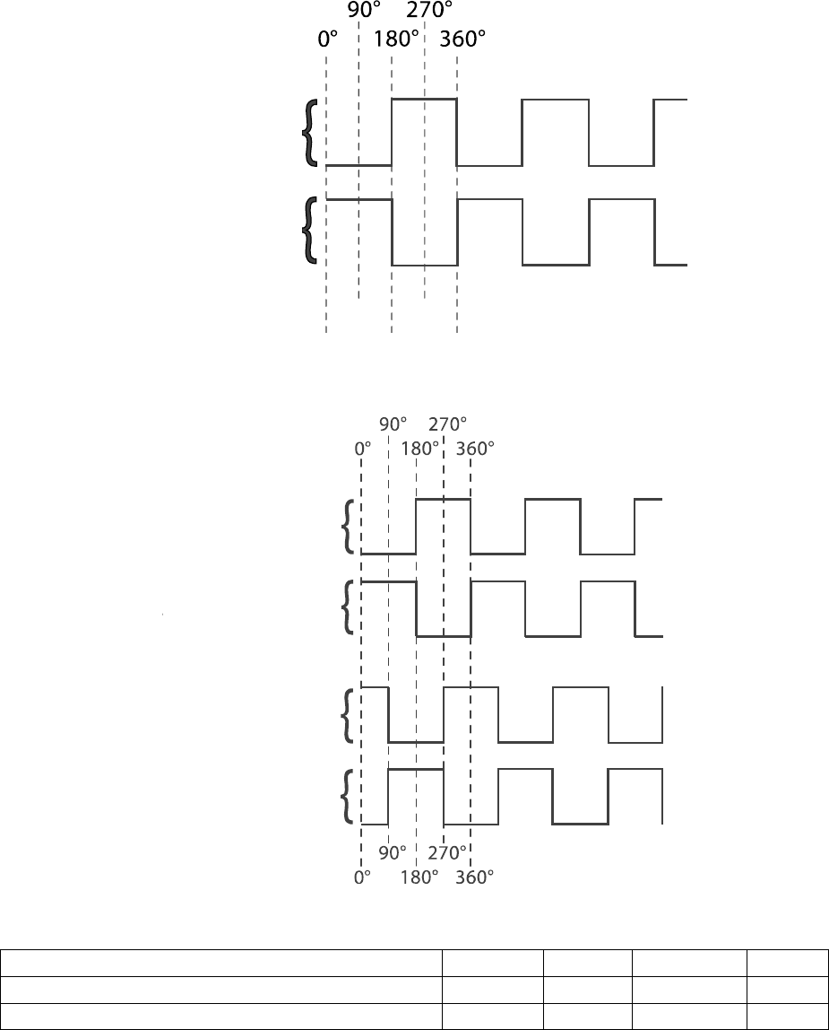
Page 96 of 126
Proton Products SL mini and SLR mini Series Speed and Length Gauges Instruction Manual - issue 1s
In quadrature mode, “Pulse output 1” and “Pulse output 2” run at the same pulse rate (set as
the “Pulse 1 rate”) with a 90° phase shift between the two outputs:
Pulse outputs electrical specifications
Specification
Minimum
Typical
Maximum
Units
Pulse output external power supply (POUT +V)
+5
+25
VDC
Pulse output frequency
2*
MHz
* reduced with increasing cable length in accordance with RS-422 standards.
P1A or P2A
/P1A or /P2A
P1A
/P1A
P2A
/P2A

Page 97 of 126
Proton Products SL mini and SLR mini Series Speed and Length Gauges Instruction Manual - issue 1s
Configuration via the PCiS_SLmini software:
1
Click the “Interface” button on the main page:
2
When prompted, enter 64000 for the password and click the “OK” button:
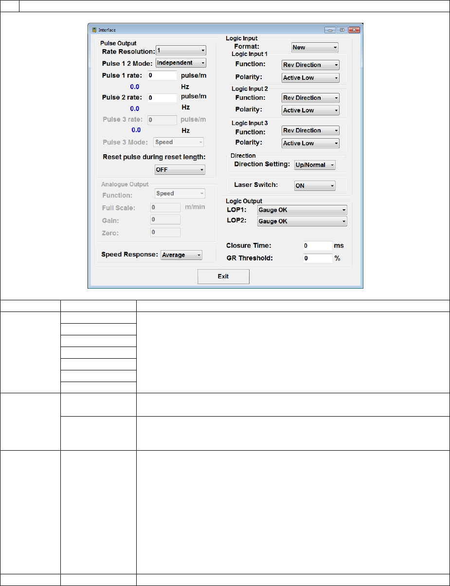
Page 98 of 126
Proton Products SL mini and SLR mini Series Speed and Length Gauges Instruction Manual - issue 1s
3
Configure the pulse output interface as required and click the “Exit” button when complete:
Label
Value*
Description
Pulse
Resolution
1000
Set the required pulse output resolution in pulses/ unit, where the unit
is the “Measurement unit” (metres, feet, inch or yards) set on the
“Measurement” page.
100
10
[1]
0.1
0.01
0.001
Pulse 1 2
Mode
[Independent]
Select “Independent” mode to configure “Pulse output 1” and “Pulse
output 2” with separate and independent pulse rates.
Quadrature
Select “Quadrature” mode to couple together “Pulse output 1” and
“Pulse output 2” as a quadrature pair, with pulse rate set under “Pulse
1 rate”.
Pulse 1
rate
1 ~
[1000]
~ 65535
Set the required pulse rate for “Pulse output 1” in pulses/unit, where
the unit is the “Measurement unit” (metres, feet, inch or yards) set on
the “Measurement” page.
Note: If the “Pulse Resolution” setting above is not suitable for the
pulse rate entered here, then the pulse rate will be automatically
rounded up or down.
When “Pulse 1 2 Mode” is set to “Quadrature”, this parameter sets the
rate for the quadrature pulse output across both “Pulse output 1” and
“Pulse output 2”.
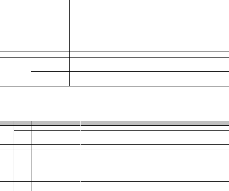
Page 99 of 126
Proton Products SL mini and SLR mini Series Speed and Length Gauges Instruction Manual - issue 1s
Pulse 2
rate
1 ~
[1000]
~ 65535
Set the required pulse rate for “Pulse output 2” in pulses/ unit, where
the unit is the “Measurement unit” (metres, feet, inch or yards) set on
the “Measurement” page.
Note: If the “Pulse Resolution” setting above is not suitable for the
pulse rate entered here, then the pulse rate will be automatically
rounded up or down.
This field is disabled when “Pulse 1 2 Mode” is set to “Quadrature”.
Reset
pulse
during
reset
length
[OFF]
Select for pulse outputs to continue following the measured speed
during a length reset.
ON
Select to reset pulse outputs when the length is reset.
* factory-default values are shown in enclosed in [ ].
Configuration by input parameters:
This interface may be configured by writing to the following input parameters:
DW
Bit
Comment
Unit
Range/Remark
Default
0
System Function
9
Pulse output 1 mode
0=Normal
1=Quadrature
0
7
Pulse output 1 rate
1=1/10DW17pulse/m{ft}{yds}
1~65535
1000
8
Pulse output 2 rate
1=1/10DW17pulse/m{ft}{yds}
1~65535
1000
17
Pulse output rate
resolution
1=1
3=1000
2=100
1=10
0=1
-1=0.1
-2=0.01
-3=0.001
0
19
Pulse reset during reset
length
0=Off
1=On
0

Page 100 of 126
Proton Products SL mini and SLR mini Series Speed and Length Gauges Instruction Manual - issue 1s
Circuit Information and Gauge Performance Indicators
The “Circuit” page of the PCiS_SLmini displays various performance indicators and gauge circuit
parameters.
1
Click the “Circuit” button on the main page:
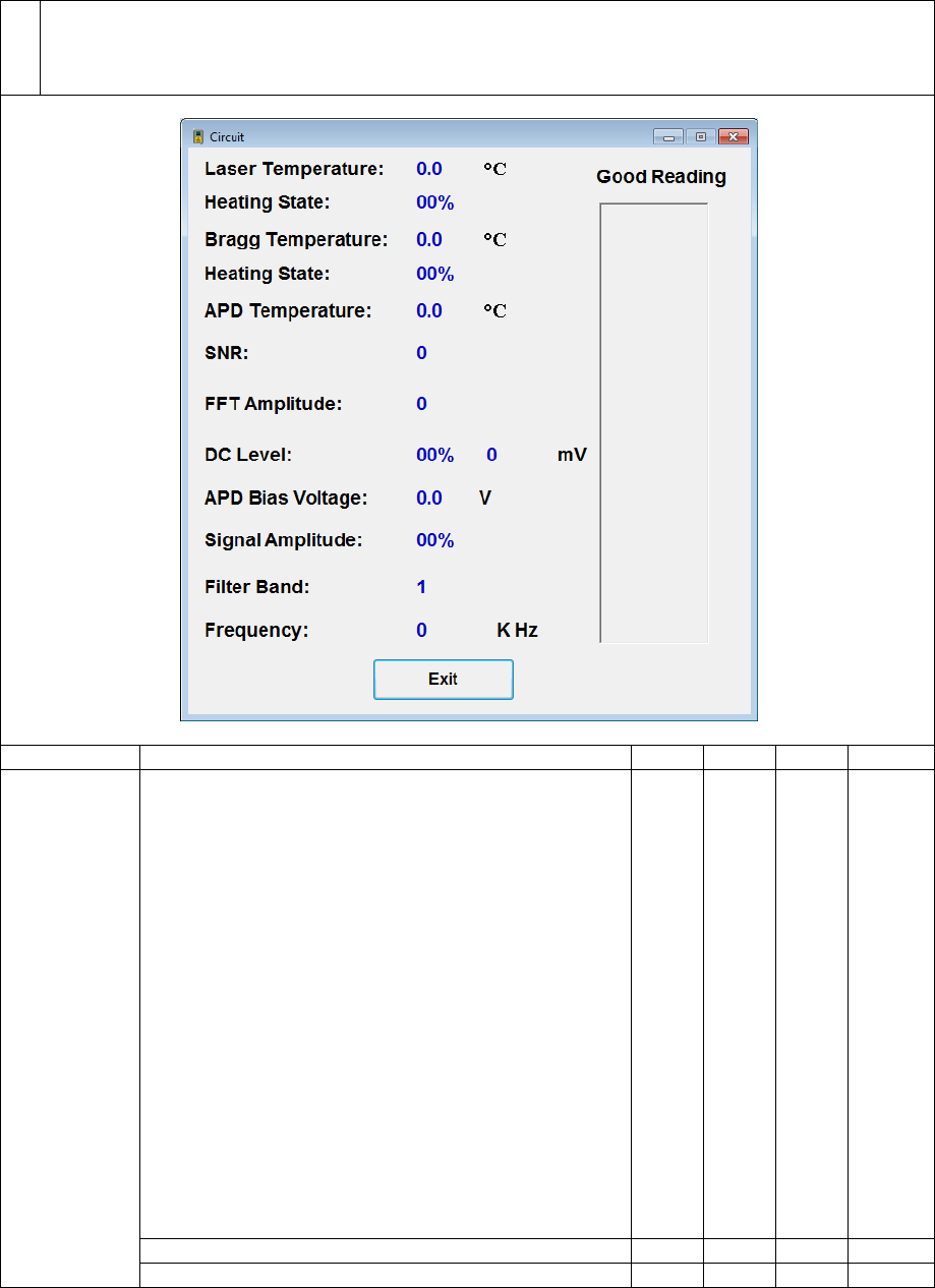
Page 101 of 126
Proton Products SL mini and SLR mini Series Speed and Length Gauges Instruction Manual - issue 1s
2
The “Circuit” page displays parameters which may be useful during gauge alignment or for
Proton Products authorized service personnel; when contacting Proton Products for technical
assistance, please have the information displayed on the “Circuit” page available for our service
personnel to better diagnose any problems.
Label
Description
Min
Typ
Max
Units
Good
Reading
The gauge attempts to sample the speed of the
object several thousand times per second; the
“Good Reading” rate represents the proportion of
samples that have yielded a valid speed reading.
Higher “Good Reading” rates result in better length
accuracy, especially over shorter object lengths.
If the surface of the object is irregular then different
areas may yield different “Good Reading” rates.
For smooth surfaces a “Good Reading” rate above
50% will produce speed and length readings of
reliably high accuracy.
In short-length measurement applications (such as
inkjet-marking or cutting, with lengths in the range
of a few metres), a “Good Reading” rate of above
80% is recommended to maintain good length
accuracy.
14
Long length (> 5 m) accuracy
50
70
100
%
Short length (0 ~ 5 m) accuracy
80
90
100
%

Page 102 of 126
Proton Products SL mini and SLR mini Series Speed and Length Gauges Instruction Manual - issue 1s
SNR
This parameter is highly-dependent on object
material, object distance to the centre of the depth-
of-field and object speed.
For example, a metal or matt-plastic surface moving
at 100 m/minute may return a SNR > 1000, but the
SNR for a translucent plastic object may be much
lower.
The signal-to-noise ratio must exceed 80 for a
consistent and reliable speed reading.
200
500
-
DC Level
(%)
The DC level depends on the amount of light
received from the object and must be between 10%
and 90% for correct operation; it is held at around
30% by an automatic gain controller (AGC).
The AGC may be saturated by highly reflective (e.g.
flat, metallic) surfaces resulting in the DC level
exceeding 100%; in this case tilt the gauge (pitch,
angle γ ≠ 0) to reduce the received light and bring
the DC level below 90%.
Very narrow or low-reflectivity objects might not
reflect sufficient light for the DC level to reach 10%;
maximise the signal by locating the object as close
to the stand-off distance (i.e. centre of the depth-of-
field).
10
30
90
%
Signal
Amplitude
Highly-reflective, uneven or fast-moving objects
may result in saturation and clipping of the received
oscillating light signal.
Signal amplitudes below 80% will not incur
saturation, whilst an Automatic Gain Controller
(AGC) will accommodate signal amplitude between
80 and 99%. Signal amplitudes above 99% will still
yield measurements but at a substantially degraded
Good Reading rate.
Maintain the signal amplitude at below 80% by
tilting the gauge (pitch, angle γ ≠ 0) to reduce the
received light.
80
%
Laser
Temperature
For use by Proton Products authorized service
personnel only.
°C
Heating
State
%
Bragg
Temperature
°C
Heating
State
%
APD
Temperature
°C
FFT
Amplitude
-
DC Level
(mV)
mV
APD Bias
Voltage
V
Filter Band
-
Frequency
kHz
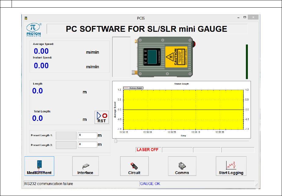
Page 103 of 126
Proton Products SL mini and SLR mini Series Speed and Length Gauges Instruction Manual - issue 1s
DATA LOGGING
The data logging function logs measurement data at regular time intervals to a .csv (comma
separated values) text file which may be opened using MS Excel and other spreadsheet software.
1
Click the “Start Logging” button on the main page:
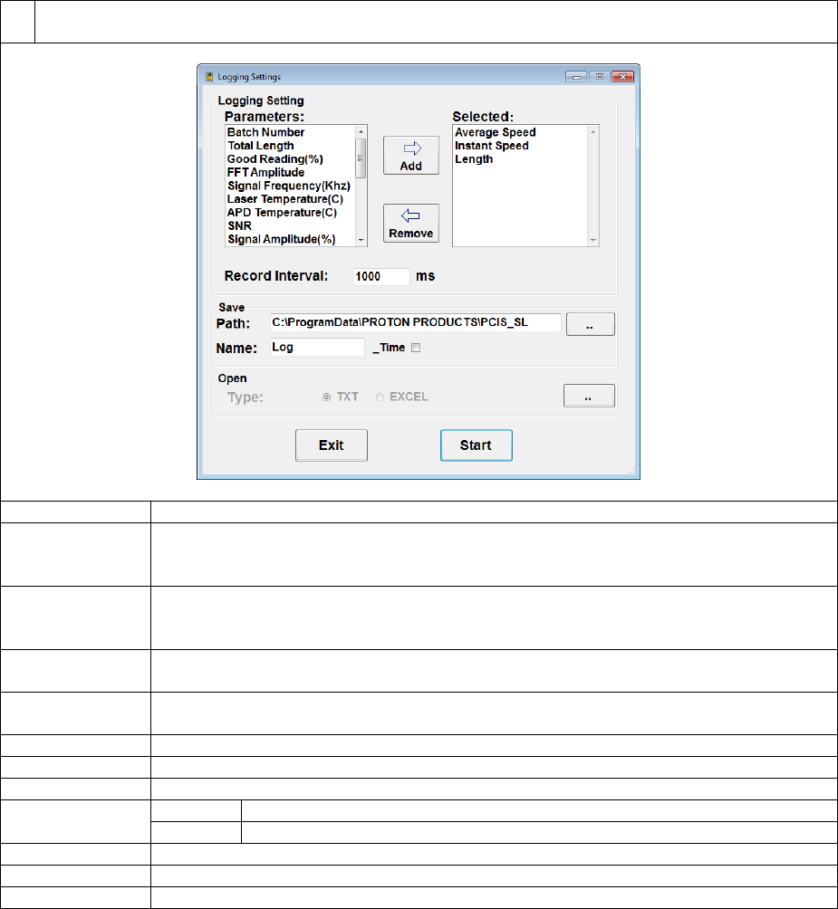
Page 104 of 126
Proton Products SL mini and SLR mini Series Speed and Length Gauges Instruction Manual - issue 1s
2
Select the required parameters to log to file, the logging time interval, file name and start/stop
logging:
Label
Description
Parameters
This displays the parameters that are available for logging; click to highlight a
parameter in this list and then click the “Add” button to move the highlighted
parameter to the “Selected” list.
Selected
This displays the parameters selected for logging; click to highlight a parameter in
this list and then click the “Remove” button to move the highlighted parameter back
to the “Parameter” list.
Add
Click this button to move a highlighted parameter from the “Parameters” list to the
“Selected” list.
Remove
Click this button to move a highlighted parameter from the “Selected” list to the
“Parameters” list.
Record Interval
Enter the interval time (in milliseconds) at which data is written to the log file.
Path
Click the “…” button to edit the path to the log file.
Name
Click to edit the name of the log file.
_Time
Ticked
Append the start time to the name of the log file.
Unticked
Do not append the start time to the name of the log file.
Start
Click to commence data logging.
Stop
Click to stop data logging.
Exit
Click to close this dialog box and return the main page.
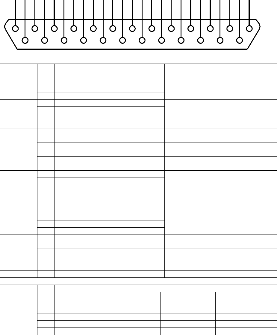
Page 105 of 126
Proton Products SL mini and SLR mini Series Speed and Length Gauges Instruction Manual - issue 1s
CONNECTOR PIN OUTS
Connector type: DB25 female (socket)
Functional
group
Pin
Designation
Description
Notes
Logic
inputs
3
LIN1
Logic input 1
Low < +3V; High > +10.5V; Max ±30V
User configurable function.
4
LIN2
Logic input 2
5
LIN3
Logic input 3
Logic
outputs
6
LOP1
Logic output 1
Floating or pull-down; user configurable
function.
7
LOP2
Logic output 2
CANbus
8
CAN H
CANbus high
For connection to Proton Products
accessories.
9
CAN L
CANbus low
Laser
safety
12
SHUT_ST
Shutter status
Pulled down to DGND when the shutter
is open.
13
/SHUT_EN
Shutter control
Pull down to DGND to open the laser
shutter.
14
/LSR_EN
Laser enable
Pull down to DGND to enable the laser
diode.
RS-232
16
RXD
RS-232 receive
17
TXD
RS-232 transmit
Pulse
outputs
1
POUT +V
Pulse output external
power supply
If no external power supply is
connected, then the pulse outputs
default to the internal +5V supply.
18
P1A
Pulse output 1
RS-422 compliant differential pair
outputs. Pulse outputs 1 and 2 may be
user-configured for independent or
quadrature operation.
19
/P1A
Inverted pulse output 1
20
P2A
Pulse output 2
21
/P2A
Inverted pulse output 2
25
+24V
Power supply
Operating voltage: 15 to 28VDC
Power consumption: 15W
2
DGND
Power supply and
signal ground
reference
15
DGND
24
DGND
Shield
S
Shield
Shield
Connect to cable and plug shields
Functional
group
Pin
Designation
Industrial bus option
Ethernet
EtherNet/IP
PROFIBUS
DeviceNET
Industrial
bus
22
IBUS1
TX+
+5V
V+
10
IBUS2
TX-
GND
V-
23
IBUS3
RX+
A
CANH
11
IBUS4
RX-
B
CANL
1
14
2
15
3
16
4
17
5
18
6
19
7
20
8
21
9
22
10
23
11
24
12
25
13
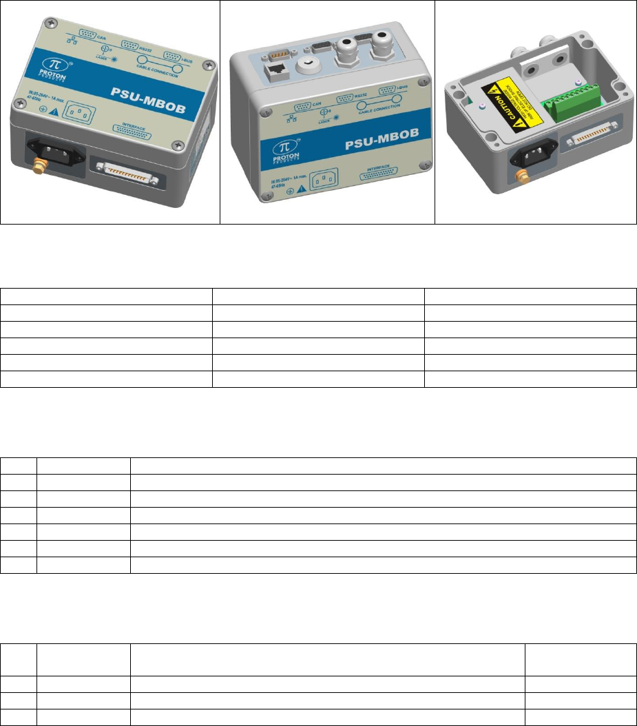
Page 106 of 126
Proton Products SL mini and SLR mini Series Speed and Length Gauges Instruction Manual - issue 1s
OPTIONAL PSU-BOB MINI
The Proton Products PSU-BOB mini (Power Supply Unit-Break Out Box-mini) is an optional
accessory for the SL mini / SLR mini series of laser speed and length gauges which provides the
following functions:
Universal AC to DC power supply
DB9 connectors for CANbus, RS-232 and optional PROFIBUS / DeviceNET communications
interfaces
RJ45 socket for Ethernet MODBUS or optional Ethernet/IP communications interface
Laser enable key switch
Screw terminals for logic inputs, logic outputs, pulse outputs and laser safety connections
The SL mini / SLR mini gauge may be connected to the PSU-BOB mini using one of the following
optional DB25-to-DB25 cables:
Length / m
Part name
Proton part no
3
SLMKII-BOB-003
00043MC021
5
SLMKII-BOB-005
00041CT005
10
SLMKII-BOB-010
00041CT010
20
SLMKII-BOB-020
00041CT020
30
SLMKII-BOB-030
00041CT030
CAN
Connector type: DB9 male (plug)
Pin
Designation
Comment
2
CANL
3
GND
Ground reference (isolated from earth / shield).
5
Shield
Ensure that the cable shield is connected to this via the plug shield connection.
7
CANH
9
+24V
+24VDC power input (the gauge may be powered via this pin).
S
Shield
Ensure that the cable shield is connected to the plug shield connection.
RS232
Connector type: DB9 female (socket)
Pin
Designation
Comment
PC DB9 serial
port pin
2
TXD1
2
3
RXD1
3
5
GND_R
Ground reference is not isolated from earth.
5

Page 107 of 126
Proton Products SL mini and SLR mini Series Speed and Length Gauges Instruction Manual - issue 1s
Pin
Designation
Comment
PC DB9 serial
port pin
7
CTS1
Not used
8
RTS1
Not used
S
Shield
Ensure that the cable shield is connected to this via the plug
shield connection.
Shield
The above table also shows the configuration of a cable for connection to a personal computer (PC)
type DB9 serial port.
I-BUS
Connector type: DB9 female (socket)
PROFIBUS
Pin
Function
Comments
3
B
5
GND
6
+5V
8
A
S
Shield
Ensure that the cable shield is connected to this via the plug shield connection.
DeviceNet
Pin
Function
Wire colour
Comment
3
CANL
Blue
5
V-
Black
6
V+
Red
8
CANH
White
S
Shield
Ensure that the cable shield is connected to this via the plug
shield connection.
Ethernet / EtherNet/IP / PROFINET
Pin
Function
Comments
1
LAN TX-
2
LAN TX+
7
LAN RX-
9
LAN RX+
S
Shield
Ensure that the cable shield is connected to this via the plug shield connection.
Note: for Ethernet, EtherNet/IP and PROFINET communications interfaces, the i-BUS DB9 socket
and RJ45 socket are wired in parallel; either one or the other connector may be used depending on
the available cable plug type.
RJ45 SOCKET
Connector type: RJ45 8P8C female (socket)
Ethernet / EtherNet/IP / PROFINET
Pin
Function
Comments
1
LAN TX+
2
LAN TX-
3
LAN RX+
6
LAN RX-
S
Shield
Ensure that the cable shield is connected to this via the plug shield connection.
Note: for Ethernet, EtherNet/IP and PROFINET communications interfaces, the i-BUS DB9 socket
and RJ45 socket are wired in parallel; either one or the other connector may be used depending on
the available cable plug type.
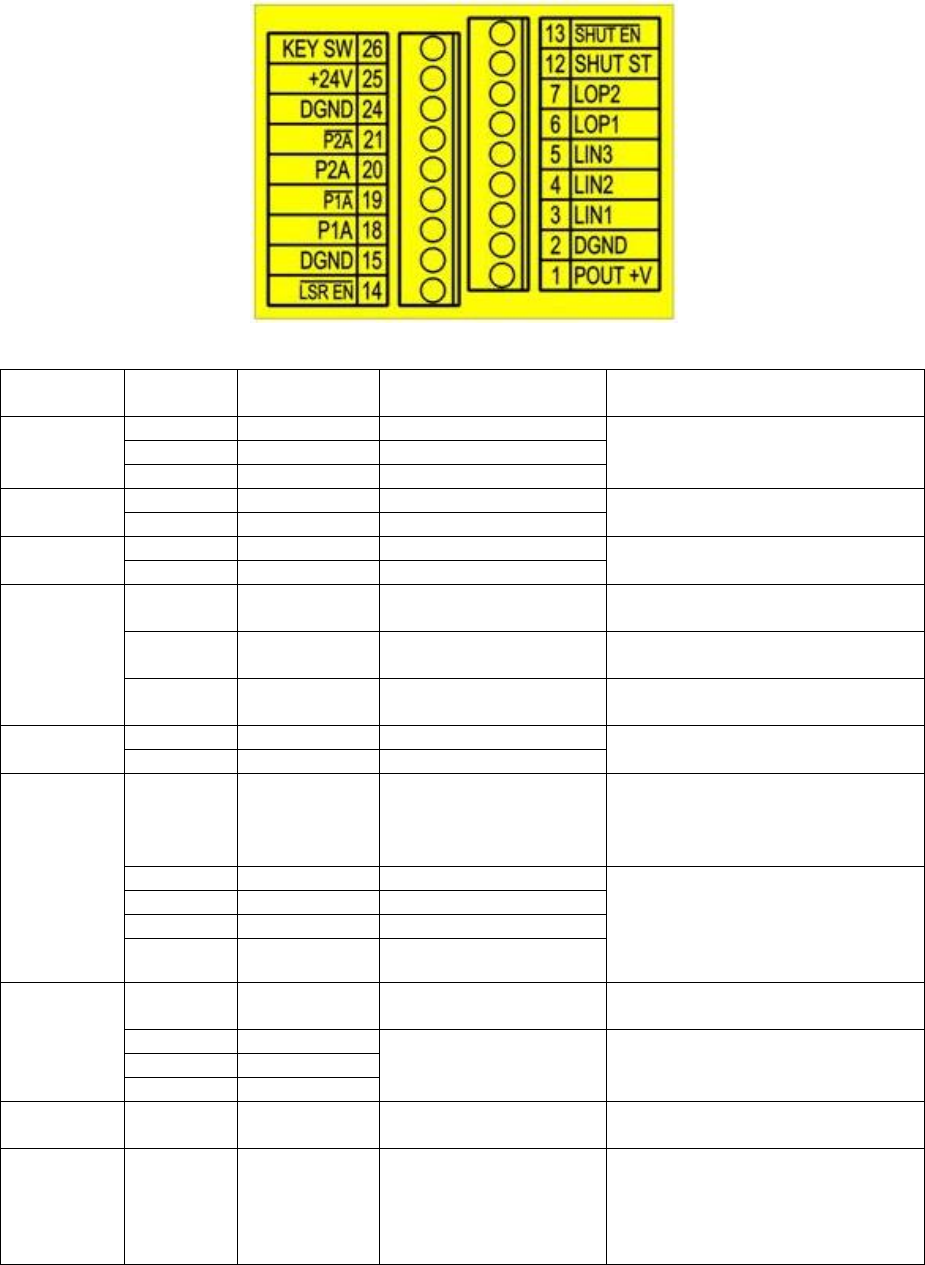
Page 108 of 126
Proton Products SL mini and SLR mini Series Speed and Length Gauges Instruction Manual - issue 1s
SCREW TERMINALS
Connector type: Screw terminals
Functional
group
Screw
terminal*
Designation
Description
Notes
Logic
inputs
3
LIN1
Logic input 1
Low < +3V; High > +10.5V; Max
±30V
User configurable function.
4
LIN2
Logic input 2
5
LIN3
Logic input 3
Logic
outputs
6
LOP1
Logic output 1
Floating or pull-down; user
configurable function.
7
LOP2
Logic output 2
CANbus
8
CAN H
CANbus high
For connection to Proton
Products accessories.
9
CAN L
CANbus low
Laser
safety
12
SHUT_ST
Shutter status
Pulled down to DGND when the
shutter is open.
13
/SHUT_EN
Shutter control
Pull down to DGND to open the
laser shutter.
14
/LSR_EN
Laser enable
Pull down to DGND to enable the
laser diode.
RS-232
16
RXD
RS-232 receive
17
TXD
RS-232 transmit
Pulse
outputs
1
POUT +V
Pulse output external
power supply
If no external power supply is
connected, then the pulse
outputs default to the internal
+5V supply.
18
P1A
Pulse output 1
RS-422 compliant differential pair
outputs. Pulse outputs 1 and 2
may be user-configured for
independent or quadrature
operation.
19
/P1A
Inverted pulse output 1
20
P2A
Pulse output 2
21
/P2A
Inverted pulse output 2
25
+24V
Power supply
Operating voltage: 15 to 28VDC
Power consumption: 15W
2
DGND
Power supply and
signal ground
reference
15
DGND
24
DGND
Shield
S
Shield
Shield
Connect to cable and plug
shields
Key-switch
26
KEY SW
Laser enable key-
switch
This terminal is connected via
the key-switch to DGND. A
removable jumper connects this
terminal to the /LSR_EN (14)
terminal.
* screw terminal numbering corresponds to the pin numbering for the DB25 INTERFACE connector
on the gauge.
Page 109 of 126
Proton Products SL mini and SLR mini Series Speed and Length Gauges Instruction Manual - issue 1s
KEY SWITCH
The key switch is provided for compliance with laser safety regulations.
When the key switch is in the open-circuited (“O”) the laser diode in the gauge is DISABLED
for laser emission.
When the key switch is in the short-circuited (“I”) the laser diode in the gauge is ENABLED for
laser emission.
After the key switch is set to the enabled (“I”) position, a warm up period is required to for the
laser diode to stabilise before measurements may be taken. The key-switch is intended for
intermittent use such as locking out the laser at the end-of-shift or during line maintenance.
A removable shorting-link connects the LSR_EN pin via the key-switch to DGND; removal of
this shorting link disables the key-switch and permits an external, user-supplied interlock
switch to be wired in place of the key-switch.
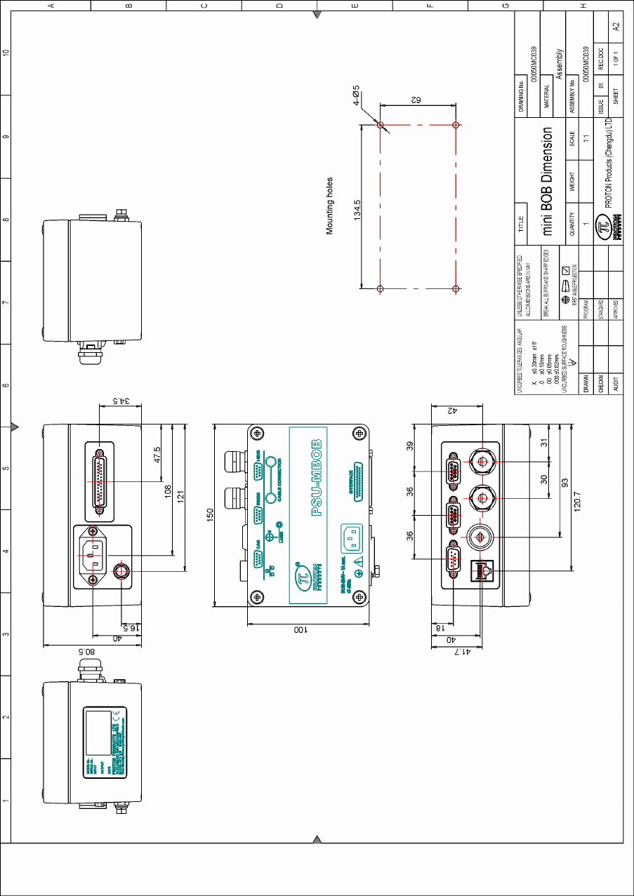
Page 110 of 126
Proton Products SL mini and SLR mini Series Speed and Length Gauges Instruction Manual - issue 1s
DIMENSIONAL DRAWING

Page 111 of 126
Proton Products SL mini and SLR mini Series Speed and Length Gauges Instruction Manual - issue 1s
INPUT PARAMETERS
1 DW word = 2 bytes 2013.08.26
DW
Bit
Comment
Unit
Range/Remark
Default
0
System Function
0
Measurement mode
0=Normal mode
1=Batch mode
0
1
Length reset
0=Reset length to zero
1=Accumulate length
1
2
Batch length reset
(available in batch mode
only)
0=Reset length to zero
1=Accumulate length
1
3
Measurement unit
0=metres
1=feet
2=yards
3=other unit(set on PCIS)
0
4
5
Speed signal output
response
0=Averaged
1=Instantaneous
1
6
Pulse output 3 mode
0=Speed
1=Length
0
7
Analogue output source
0=Speed
1=Good Readings
0
8
Length / speed
resolution
0=Length 0.1 / speed 0.01
1=Length 0.0001 / Speed
0.001
1
9
Pulse output 1 mode
0=Normal
1=Quadrature
0
10
Automatic save length
function
0=Invalid
1=Valid
0
11
Object detection switch
0=Off
1=On
0
12
Auto reset when object
detected
0=Off
1=On
0
13
Reset reel number
0=Normal
1=Reset reel number to
zero
0
14~15
Not used
0
1
Preset 1 and 2 decimal
point position
-3~3
0
2
Averaging time
1=5ms
1~1000 (5~5000ms)
200
3
No speed signal hold
time
1=1ms
1~5000 (1ms~5s)
100
4
Batch mode LOP
closure time
1=10ms
1~500 (10ms~5s)
50
5
Preset length 1 or
Preset batch length
1=1/10DW1m{ft}{yds{inch}}
0~65535
1000
6
Preset length 2 or
Preset batch number
1=1/10DW1m{ft}{yds}{inch}
1=1(batch number)
0~65535
2000
7
Pulse output 1 rate
1=1/10DW17pulse/m{ft}{yds}
1~65535
1000
8
Pulse output 2 rate
1=1/10DW17pulse/m{ft}{yds}
1~65535
1000
9
Pulse output 3 rate
1=1/10DW17pulse/m{ft}{yds}
1~65535
1000
10
Analogue output full
scale
1=1m/min{ft/min}
100~9999
3000
11
Minimum speed limit
1=0.1m/min{ft/min}
0~65535 (0~6553.5)
0
12
Logic input (old format: compatible with old SL gauge;DW12.15=0)
0
Logic input 1 function
0=Direction
1=Length hold
2=Display hold
3=Speed hold
1
1
2
Direction setting
(available only when no
logic input for direction)
0=Count up
1=Count down
0
3
Logic input 1 polarity
0=Active low
1=Active high
0
4~7
Not used
0
8
Logic input 2 function
0=Reset input
1=Length hold
0
9
10
Logic input 2 polarity
0=Active low
1=Active high
0
11
Logic input 3 function
0=Direction
1=Length hold
2=Display hold
1
12
13
Page 112 of 126
Proton Products SL mini and SLR mini Series Speed and Length Gauges Instruction Manual - issue 1s
DW
Bit
Comment
Unit
Range/Remark
Default
3=Speed hold
4=Reset
14
Logic input 3 polarity
0=Active low
1=Active high
0
15
Must be 0
0=Old format logic inputs
0
12
Logic input(new format;DW12.15=1)
0
Logic input 1 function
0=Direction (count down)
1=Length hold
2=Display hold
3=Speed hold
4=Reset total length
5= End of Reel / Reset batch
length
0
1
2
3
Logic input 1 polarity
0=Active low
1=Active high
0
4
Logic input 2 function
0=Direction (count down)
1=Length hold
2=Display hold
3=Speed hold
4= Reset total length
5=End of Reel / Reset batch
length
1
5
6
7
Logic input 2 polarity
0=Active low
1=Active high
0
8
Logic input 3 function
0=Direction (count down)
1=Length hold
2=Display hold
3=Speed hold
4= Reset total length
5= End of Reel / Reset batch
length
4
9
10
11
Logic input 3 polarity
0=Active low
1=Active high
0
12
Direction setting
(available only when no
logic input for direction)
0=Count up
1=Count down
0
13~14
Not used
15
Must be 1
1=New format logic inputs
13
Laser switch
0=Laser on
1=Laser off
0
14
Length offset
1=0.1m{ft}{yds}{inch}
-3000.0~3000.0m{ft}{yds}
0
15
Pulse output 3 preset
length
1=0.001m{ft}{yds}
1000
16
Logic output function
0~3
LOP1 function
0=Gauge OK
1=Gauge measuring speed
2=Preset length 1 / Batch length
3=Preset length 2 / Batch
number
4=Good reading
5=Object detected
6=Gauge too hot
13=User 1
14=User 2
15=User 3
0
4~7
LOP2 function
2
8~11
LOP3 function
3
13
User I/P 1
0=OPEN
1=CLOSE
14
User I/P 2
0=OPEN
1=CLOSE
15
User I/P 3
0=OPEN
1=CLOSE
17
Pulse output rate
resolution
1=1
3=1000
2=100
1=10
0=1
-1=0.1
-2=0.01
-3=0.001
0
18
Good Reading threshold
1=1%
60%
19
Pulse reset during reset
length
0=Off
1=On
0
20
Profibus address
1=1
0~125
7

Page 113 of 126
Proton Products SL mini and SLR mini Series Speed and Length Gauges Instruction Manual - issue 1s
DW
Bit
Comment
Unit
Range/Remark
Default
21
CAN address
1=1
0~255
14
22
CAN baud rate
0=250
1=500
2=1000
other=500
2
23
RS232 baud rate
0=4800
1=9600
2=19200
3=38400
4=115200
1
24
RS232 mode
0=Proton protocol
1=Modbus protocol
2=ZM400 Printer
1
25
RS422/RS485 mode
0=Proton protocol
1=Modbus protocol
2=SSI speed protocol
3=SSI length protocol
1
26
RS422/RS485 baud rate
0=4800
1=9600
2=19200
3=38400
4=115200
5=250K
6=500K
7=1M
1
27
Modbus address
1=1
0~255
1
28
EtherNet protocol
0=Modbus protocol
1=EIP protocol
0
29
DHCP
0=Disabled
1=Enabled
0
30
IP address
x.x.x.x
C0A8016E
(192.168.1.110)
31
32
Subnet mask
x.x.x.x
FFFF0000
(255.255.0.0)
33
34
Gateway
x.x.x.x
C0A80001
(192.168.1.1)
35
36
CAN terminator
1=1
0=Off
1=On
0
37
0=Proton pro
38
Speed compensation
coefficient
1=0.0001
10000
39
Acceleration limit
1=1m{ft}{yd}/min/s
1~9999
9999
40
Reset parameters to
factory defaults
63000=factory default
other=invalid
41
UDP data output interval
time
1=1ms
1~5000
0=Disable UDP output
0
42
Analogue O/P gain
1=0.0001
9999
43
Analogue O/P zero
1=0.0001
0
44
Speed simulation
0=Normal
1=Simulation
0
45
Simulation speed
1=0.1m{ft}{yds}/min
0~6553.5
100
46
DeviceNet address
0~63
7
47
DeviceNet baud rate
0=125K
1=250K
2=500K
48
UDP destination IP
address (last octet only)
Note: the UDP destination port
number is fixed at 1111
2
49
Endianess
1=Little endian
0=Big endian
0

Page 114 of 126
Proton Products SL mini and SLR mini Series Speed and Length Gauges Instruction Manual - issue 1s
OUTPUT PARAMETERS
1 DW word = 2 bytes 2013.08.26
DW
Bit
Comments
Units
Range/Remark
0
0
Mode
0=Normal
1=Batch
1
Length / speed resolution
0=Length 0.1 / speed 0.01
1=Length 0.0001 / speed
0.001
2
Not used
3
Measured length >= Preset1
1=>Preset
4
Measured length >= Preset2
1=>Preset
5
Length reset
0=Reset
6
Measurement unit
0=Metres
1=Feet
2=Yards
3=other unit (set on PCIS)
7
8
Speed signal output response
0=Averaged
1=Instantaneous
9
10
Laser status
1=Laser on
0=Laser off
11
Gauge OK
1=Gauge OK
12
Speed reading validity
1=Valid
0=Invalid
13
Object detected
1=Object detected
0=No object
14
Good reading status
1=Lower than threshold
0=OK
15
Not used
1
0
Gauge OK
1=Error
0=OK
1
Laser temperature too high
1=Too high
0=OK
2
Laser temperature too low
1=Too low
0=OK
3
APD temperature too high
1=Too high
0=OK
4
APD temperature too low
1=Too low
0=OK
5
APD DC level
1=Too high
0=OK
6
Gauge too hot
1=Too hot
0=OK
7
Not used
8
Not used
2
Average speed
Old format: 1=0.01m/min {ft/min} {yds/min}
New format: 1=0.001m/min{ft/min}{yds/min}
±10~999999
(0.10~9999.99)
3
4
Instant speed
±10~999999
(0.10~9999.99)
5
6
Total length / Batch length (when in
batch mode)
Old format: 1=0.1m{ft}{yds}{inch}
New format: 1=0.0001m{ft}{yds}{inch}
±200,000.0000
7
8
Logic input
0
Not used
1
Direction
0=Count up
1=Count down
2
Logic input 1 function
0=Direction
1=Length hold
2=Display hold
3=Speed hold
3
4
Logic input 1 state
1=Active
5~7
8
Logic input 2 function
0=Reset input
1=Length hold
9
10
Logic input 2 state
1=Active
11
Direction
0=Count up
1=Count down
12
Length hold
1=Hold
13
Display hold
1=Hold
14
Speed hold
1=Hold

Page 115 of 126
Proton Products SL mini and SLR mini Series Speed and Length Gauges Instruction Manual - issue 1s
DW
Bit
Comments
Units
Range/Remark
15
Length reset
1=Reset
9
Not used
10
Batch number
1=1
11
Not used
SNR
12
Total length
1=0.1m{ft}{yds}{inch}
±200,000.0000
13
14
Good readings percentage
1=1%
0~100
15
Not used
Signal amplitude
16
Not used
17
Not used
18
Not used
19
Not used
20
i-BUS communications bus type
0=Modbus_TCP
1=PROFIBUS
2=DeviceNET
3=Ethernet/IP
4=PROFINET
21
DHCP
0=Enable
1=Disable
22
IP address
x.x.x.x
23
24
Subnet mask
x.x.x.x
25
26
Gateway
x.x.x.x
27
28
Not used
29
Not used
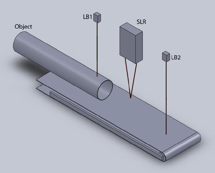
Page 116 of 126
Proton Products SL mini and SLR mini Series Speed and Length Gauges Instruction Manual - issue 1s
APPENDIX 1: HIGH ACCURACY LENGTH MEASUREMENT OF
DISCRETE OBJECTS APPLICATION NOTE
PROBLEM
Length measurement of discrete objects moving on a production line may incur errors due to the
tracking delay / hold time of the SL / SLR / SL mini / SLR mini gauge as individual objects enter and
leave the gauge measurement spot.
SOLUTION
Use two accurately spaced light barriers connected to the logic inputs of the gauge to trigger length
measurement only after the object is in position for accurate speed measurement by the gauge.
One light barrier (LB1) is installed upstream of the gauge and one light barrier (LB2) is installed
downstream of the gauge. “L” is the accurately measured distance between LB1 and LB2.
The gauge is configured to measure length only when both LB1 and LB2 are interrupted by the
object. The gauge thus measures the length of the object minus a section corresponding to the
distance between LB1 and LB2:
Object length = L + (gauge measured length)
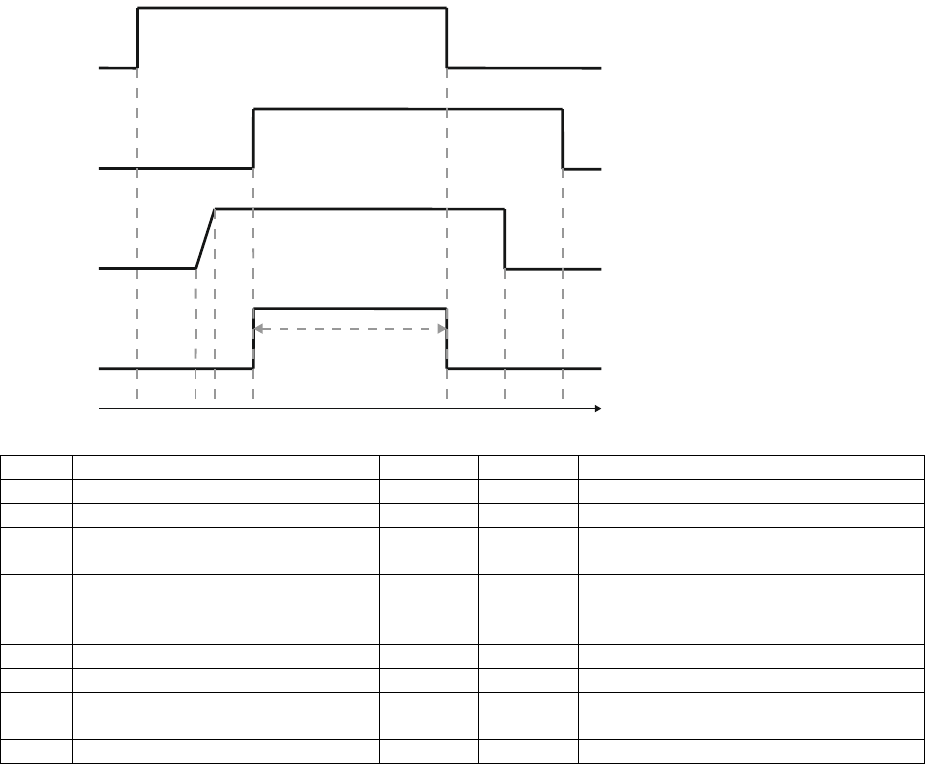
Page 117 of 126
Proton Products SL mini and SLR mini Series Speed and Length Gauges Instruction Manual - issue 1s
Time
Object status
LB1
LB1
SL / SLR status
T0
Clear of LB1, LB2, SL / SLR
Clear
Clear
No object
T1
Leading edge interrupts LB1
Blocked
Clear
No object
T2
Leading edge enters gauge
measurement spot
Blocked
Clear
Object detected but speed
measurement not yet valid
T3
-
Blocked
Clear
Speed measurement valid (but not
displayed/output in “Length hold”
mode)
T4
Leading edge interrupts LB2
Blocked
Blocked
Length measurement starts
T5
Trailing edge clears LB1
Clear
Blocked
Length measurement ends
T6
Trailing edge clears gauge
measurement spot
Clear
Blocked
Speed measurement ends
T7
Trailing edge clears LB2
Clear
Clear
No object
The distance between the gauge gauge and LB2 must be large enough to allow the gauge sufficient
time to generate valid speed measurements before the object reaches LB2 and triggers length
measurement. Distance “L” between LB1 and LB2 must also be less than the minimum object length.
IMPLEMENTATION
Light barriers LB1 and LB2 can be connected to any 2 of the 3 logic inputs provided on the gauge.
The behaviour of the gauge can be configured to trigger length measurement only when both LB1
and LB2 are blocked.
Both logic inputs should be configured to “Length hold” mode. An active logic input in “Length hold”
mode will cause the gauge to freeze length readings and force the displayed speed to zero (however,
internally the gauge will continue to accurately measure speed if an object is present). Hence each
logic input should be configured to be active when its corresponding light barrier is clear.
A “Length offset” corresponding to the distance “L” between the two light barriers can also be
programmed in to gauge. The gauge will then automatically add this “Length offset” to its length
measurement display and output.
The length measurement generated by the gauge will be ready to read by other production control
equipment when the output of LB1 transitions from blocked-to-clear (the object’s trailing edge passes
through LB1). A momentary pulse may be sent to the third logic input on the gauge to reset the length
measurement once it has been read out by other production control equipment.
LB 1
LB 2
Gauge speed
measurement
Gauge length
length
measurement
H
L
H
L
Active
Inactive
Active
Inactive
T1
T2
T3
T4
T5
T6
T7
T0
Time
Measured length
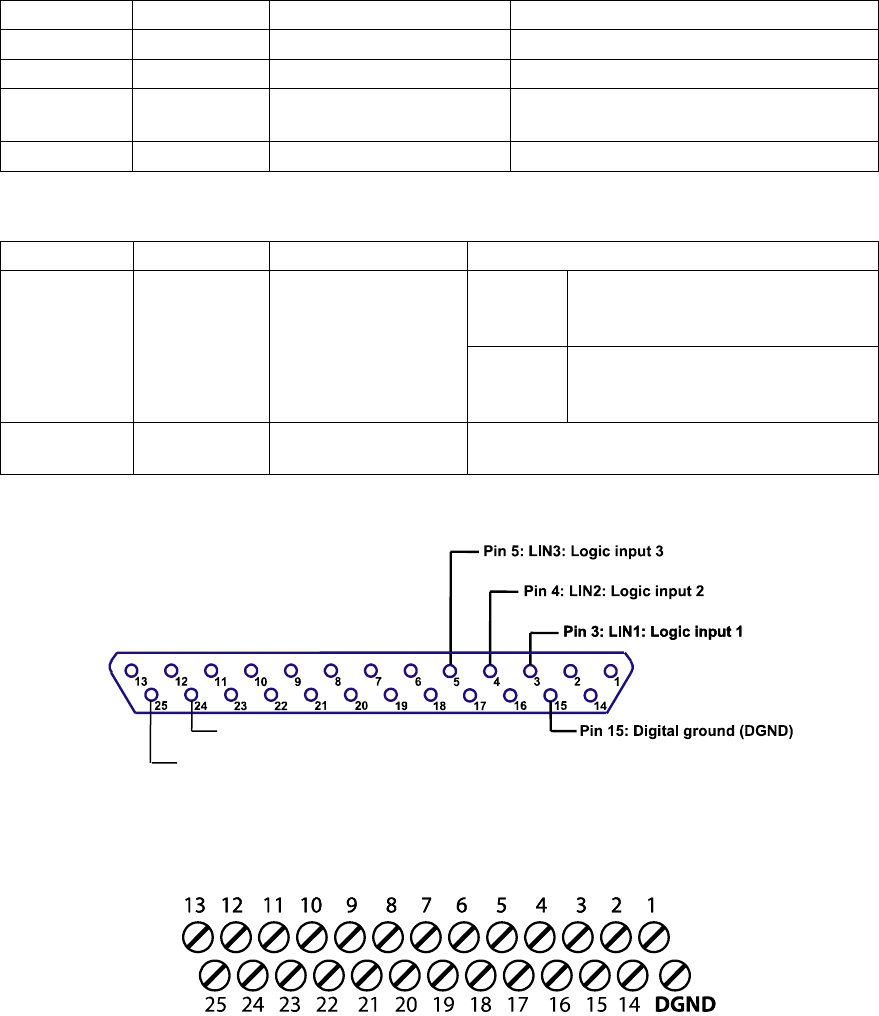
Page 118 of 126
Proton Products SL mini and SLR mini Series Speed and Length Gauges Instruction Manual - issue 1s
Connections to the SL / SLR / SL mini / SLR mini gauge
SL / SLR / SL mini / SLR mini gauges provide three user configurable logic inputs to connect to light
barriers LB1 and LB2 and also to a reset pulse input from other production control equipment for
resetting the length measurement. Access to these inputs is either via:
1. The DB25 INTERFACE socket on the gauge.
2. The screw terminal board in an optional PSU-BOB-SL combination power supply and
breakout box (for SL and SLR gauges) or a PSU-BOB-SL-mini (for SL mini and SLR mini
gauges).
Pin / Screw
Designation
Designation full name
Suggested application
3
LIN 1
Logic input 1
LB1 – Length hold mode
4
LIN 2
Logic input 2
LB2 – Length hold mode
5
LIN 3
Logic input 3
Reset length measurement pulse (no
shorter than 1ms in duration)
15
DGND
Digital ground
Ground reference for LB1 and LB2
Power for +24VDC light barriers may be derived from the +24VDC power rail of the gauge:
Pin / Screw
Designation
Designation name
Suggested application
24
REG. GND
Power rail ground
SL /
SLR
User must externally connect
this pin to DGND (pin 15) if used
to power +24VDC light barriers
SL mini
/ SLR
mini
Already internally connected
inside the SL mini / SLR mini to
DGND (pin 15).
25
+24V
+24VDC power rail
May be used to power +24VDC light
barriers.
DB25 INTERFACE Socket Logic Input Pin Designations
Connector type: DB25 Female Socket
PSU-BOB-SL Screw Terminal Designations (for SL and SLR gauges only):
PSU-BOB-SL screw terminal numbers correspond directly to DB25 interface socket pin numbers.
In addition to screw terminal 15, an additional Digital Ground (DGND) terminal is provided on the
PSU-BOB-SL screw terminal board.
Pin 24: REG. GND: Power supply ground
Pin 25: +24V: +24VDC Power supply
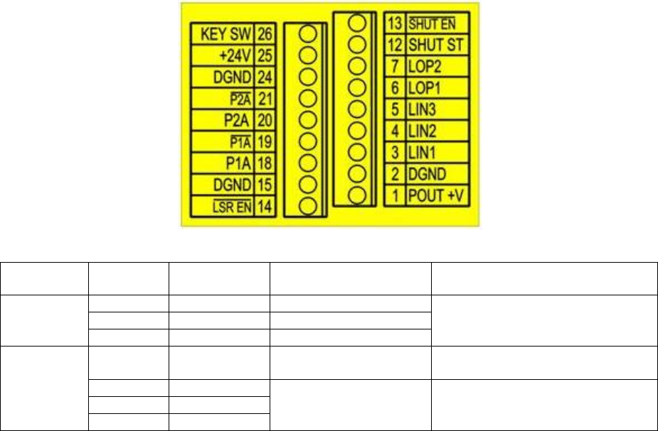
Page 119 of 126
Proton Products SL mini and SLR mini Series Speed and Length Gauges Instruction Manual - issue 1s
PSU-BOB-SL-mini Screw Terminal Designations (for SL mini and SLR mini gauges only):
Connector type: Screw terminals
Functional
group
Screw
terminal
Designation
Description
Notes
Logic
inputs
3
LIN1
Logic input 1
Low < +3V; High > +10.5V; Max
±30V
User configurable function.
4
LIN2
Logic input 2
5
LIN3
Logic input 3
25
+24V
Power supply
Operating voltage: 15 to 28VDC
Power consumption: 15W
2
DGND
Power supply and
signal ground
reference
15
DGND
24
DGND
PSU-BOB-SL-mini screw terminal numbers correspond directly to DB25 interface socket pin numbers.
Logic input electrical characteristics
Logic inputs are referenced to pin 15 (DGND). Pin 15 is internally connected to the enclosure
earth so all voltages are also referenced to earth.
A low state (logic 0) is defined as a voltage below +3V.
A high state (logic 1) is defined as a voltage above +10.5V.
The safe input voltage range is –30V to +30V.
All inputs are internally pulled up via a 5.1kΩ resistor to an internal +15V source, thus inputs left
open circuit default to the high state.
The logic input requires a current of 3mA to pull it down to the low state.
Connection to the logic input depends on the signal source as follows:
Solid state or mechanical relay contact: connect between pin 15 (DGND) and logic input pin.
Pull-down: Connect ground to pin 15 (DGND) and signal to the logic input pin.
Pull-up: Connect an 820kΩ resistor from the logic input pin to pin 15 (DGND); this will pull down
the input to 2.5V when the pull-up is switched off. Connect ground to pin 15 (DGND) and signal to
the logic input pin. If the signal is 24V, then power loss in the resistor across the input can be
reduced by adding an 820kΩ resistor in series with the signal.
Gauge software configuration
The behaviour of the gauge can be configured via RS232, the optional AiG2 display unit or optional
PCIS software. The following three configuration settings need to be adjusted:
1. Configure both light barrier logic input functions to “Length hold” mode.
2. Configure both light barrier logic input active states to active when the light barriers are clear
(no object):
Page 120 of 126
Proton Products SL mini and SLR mini Series Speed and Length Gauges Instruction Manual - issue 1s
LB1, LB2 output when clear (no object)
“Length hold” logic input active state
Low (pull down)
Active low
High (pull up)
Active high
3. Configure reset logic input function to “Reset length” mode.
4. Configure reset logic input active state to active high or active low as required.
5. Configure “Length offset” to distance “L” between LB1 and LB2.
SL / SLR gauge configuration using the optional AiG2 display unit:
Navigate to the “Interface” menu and then navigate to the following submenus:
Logic input function:
Select “Length hold” for each light barrier logic input.
Select “Reset length” for the reset pulse logic input.
Logic input active state:
Select “Active high” or “Active low” for each logic input.
Navigate to the “Measurement” menu and then navigate to the following submenu:
Length offset:
Set a positive value corresponding to distance “L”.
Note: If the default resolution of 1=0.1 m (or ft or yds or inch) of the “Length Offset” parameter is too
large, then an enhanced resolution “Length Offset” of 1=0.001 m (or ft or yds or inch) can be factory-
enabled in the SL / SLR gauge.
SL / SLR gauge configuration via RS232:
The following input parameters can be programmed via RS232 (and other optionally installed
interfaces) on the SL / SLR gauge. For further information regarding the data format for programming
parameters, please consult the SL / SLR gauge instruction manual.
DW
Data
bit
Comments
Value
12
0
Logic input 1 function
1= Length hold
4= Reset length [if signal held for 5s, resets reel number]
1
2
3
Logic input 1 polarity
0 = active low (pulled down)
1 = active high (pulled up)
4
Logic input 2 function
1 = Length hold
4= Reset length [if signal held for 5s, resets reel number]
5
6
7
Logic input 2 polarity
0 = active low (pulled down)
1 = active high (pulled up)
8
Logic input 3 function
1 = Length hold
4= Reset length [if signal held for 5s, resets reel number]
9
10
11
Logic input 3 polarity
0 = active low (pulled down)
1 = active high (pulled up)
DW
Comments
Unit
Range
Value
14
Length offset
1=0.1m{ft}{yds}{inch}
3000.0~3000.0m{ft}{yds}{inch}
Set to distance “L”
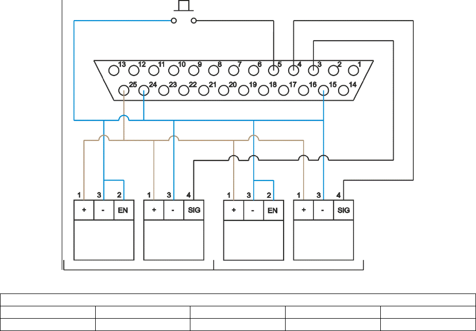
Page 121 of 126
Proton Products SL mini and SLR mini Series Speed and Length Gauges Instruction Manual - issue 1s
Note: If the default resolution of 1=0.1 m{ft}{yds}{inch}of the “Length Offset” (DW14) parameter is too
large, then an enhanced resolution “Length Offset” of 1=0.001 m{ft}{yds}{inch} can be factory-enabled
in the SL / SLR gauge.
EXAMPLE IMPLEMENTATION USING BANNER QS18 LASER EMITTERS AND
QS186LE NPN SENSORS
DB25 INTERFACE Socket Connection
QS186LE Laser Emitter / QS18 NPN Sensor wiring colour code
Pin
1
2
3
4
Colour
Brown
White
Blue
Black
When no object is present, laser light from the QS186LE laser emitter illuminates the QS18 NPN
sensor and its SIG output is pulled low; hence the SL / SLR gauge “Length hold” function must be set
to “active low”.
SL / SLR gauge configuration using the optional AiG2 display unit:
Navigate to the “Interface” menu and then navigate to the following submenus:
Logic input function:
Select “Length hold” for logic inputs 1 and 2.
Select “Reset length” for logic input 3.
Logic input active state:
Select “Active low” for logic inputs 1, 2 and 3.
Navigate to the “Measurement” menu and then navigate to the following submenu:
Length offset:
Set a positive value corresponding to distance “L”.
SL / SLR INTERFACE port
Connector type: DB25 Female Socket
LB1
LB2
QS186LE
Laser
Emitter
QS186LE
Laser
Emitter
QS18
NPN
Sensor
QS18
NPN
Sensor
Reset Length switch
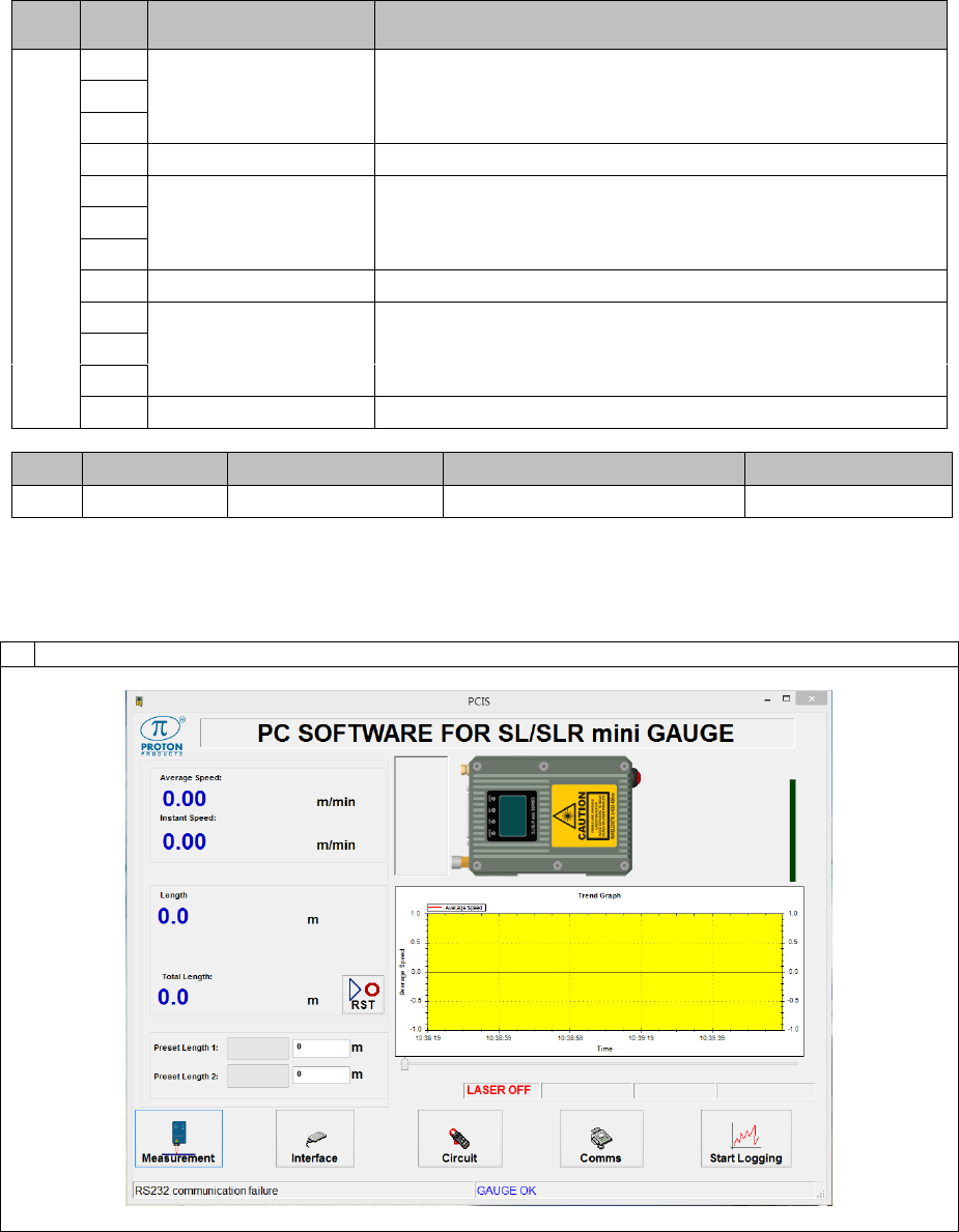
Page 122 of 126
Proton Products SL mini and SLR mini Series Speed and Length Gauges Instruction Manual - issue 1s
SL / SLR gauge configuration via RS232:
The following input parameters can be programmed via RS232 (and other optionally installed
interfaces) on the SL / SLR gauge. For further information regarding the data format for programming
parameters, please consult the SL / SLR gauge instruction manual.
DW
Data
bit
Comments
Value
12
0
Logic input 1 function
1= Length hold
1
2
3
Logic input 1 polarity
0 = active low (pulled down)
4
Logic input 2 function
1 = Length hold
5
6
7
Logic input 2 polarity
0 = active low (pulled down)
8
Logic input 3 function
4= Reset length [if signal held for 5s, resets reel number]
9
10
11
Logic input 3 polarity
0 = active low (pull-down)
DW
Comments
Unit
Range
Value
14
Length offset
1=0.1m{ft}{yds}{inch}
3000.0~3000.0m{ft}{yds}{inch}
Set to distance “L”
SL mini / SLR mini configuration
Configuration via the PCiS_SLmini software:
1
Click the “Interface” button on the main page:
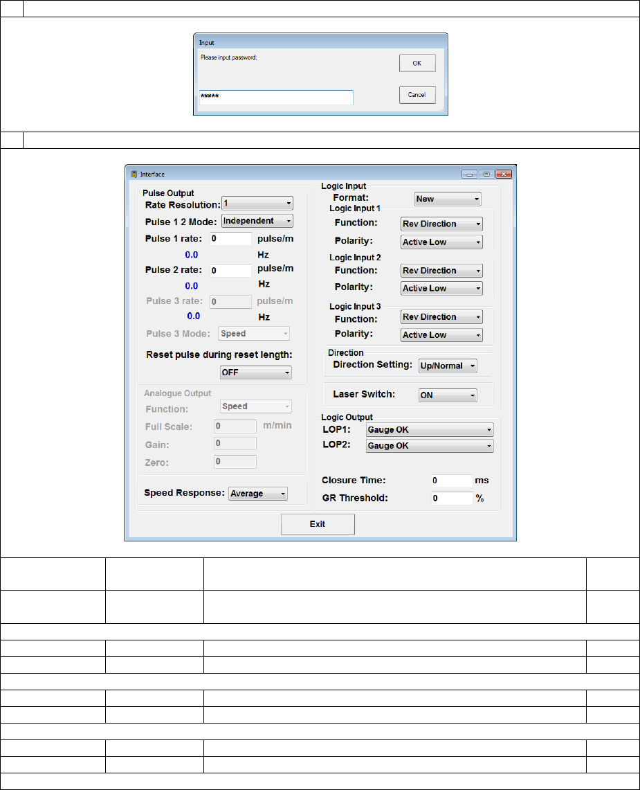
Page 123 of 126
Proton Products SL mini and SLR mini Series Speed and Length Gauges Instruction Manual - issue 1s
2
When prompted, enter 64000 for the password and click the “OK” button:
3
Configure the logic input interfaces as follows and then click the “Exit” button:
Label
Value
Description
Input
DW
Format
New
12.15
Logic Input 1
Function
Length Hold
12
Polarity
Active Low
12
Logic Input 2
Function
Length Hold
12
Polarity
Active Low
12
Logic Input 3
Function
Reset
12
Polarity
Active Low
12
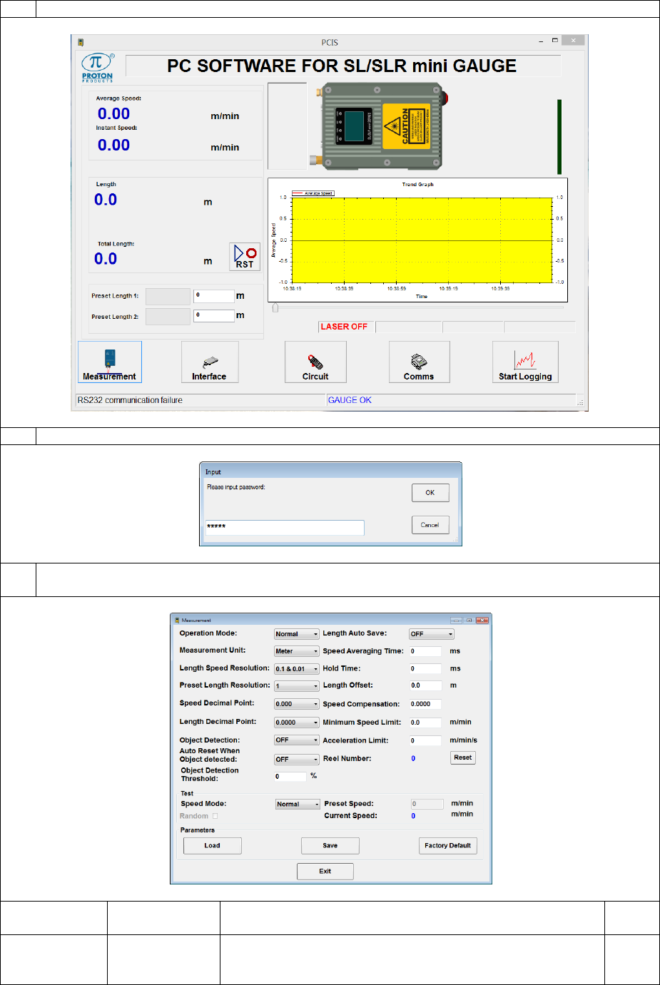
Page 124 of 126
Proton Products SL mini and SLR mini Series Speed and Length Gauges Instruction Manual - issue 1s
4
Click the “Measurement” button on the main page:
5
When prompted, enter 63000 for the password and click the “OK” button:
6
Configure the “Length Offset” to the distance between the light barriers and then click the “Exit”
button:
Label
Value*
Description
Input
DW
Length Offset
-3000.0 ~
3000.0
m{ft}{yds}{inch}
Set the required length offset value.
14
Page 125 of 126
Proton Products SL mini and SLR mini Series Speed and Length Gauges Instruction Manual - issue 1s
Configuration by input parameters:
This interface may be configured by writing to the following input parameters:
Input parameters
DW
Bit
Comment
Unit
Range/Remark
Default
12
Logic input(new format;DW12.15=1)
0
Logic input 1 function
1=Length hold
0
1
2
3
Logic input 1 polarity
0=Active low
0
4
Logic input 2 function
1=Length hold
1
5
6
7
Logic input 2 polarity
0=Active low
0
8
Logic input 3 function
4=Reset
4
9
10
11
Logic input 3 polarity
0=Active low
0
12
Direction setting (available
only when no logic input
for direction)
0=Count up
1=Count down
0
13~
14
Not used
15
Must be 1
1=New format logic inputs
DW
Bit
Comment
Unit
Range/Remark
Default
14
Length offset
1=0.1m{ft}{yds}{inch}
-3000.0~3000.0m{ft}{yds}{inch}
0

This device complies with Part 15 of the FCC Rules. Operation is subject to the following two
conditions: (1) this device may not cause harmful interference, and (2) this device must accept
any interference received, including interference that may cause undesired operation.
The users manual or instruction manual for an intentional or unintentional radiator shall
caution the user that changes or modifications not expressly approved by the party responsible
for compliance could void the user's authority to operate the equipment. In cases where the
manual is provided only in a form other than paper, such as on a computer disk or over the
Internet, the information required by this section may be included in the manual in that
alternative form, provided the user can reasonably be expected to have the capability to access
information in that form.
This equipment has been tested and found to comply with the limits for a Class A digital
device, pursuant to part 15 of the FCC Rules. These limits are designed to provide reasonable
protection against harmful interference when the equipment is operated in a commercial
environment. This equipment generates, uses, and can radiate radio frequency energy and, if
not installed and used in accordance with the instruction manual, may cause harmful
interference to radio communications. Operation of this equipment in a residential area is
likely to cause harmful interference in which case the user will be required to correct the
interference at his own expense.
Radiation Exposure Statement
This equipment complies with FCC radiation exposure limits set forth for an uncontrolled
environment. This equipment should be installed and operated with minimum distance 20cm
between the radiator & your body.

Page 126 of 126
Proton Products SL mini and SLR mini Series Speed and Length Gauges Instruction Manual - issue 1s
CONTACT DETAILS FOR ENQUIRIES, SALES AND SERVICE
WEB SITE www.protonproducts.com
ENQUIRIES AND SALES
USA head office:
European head office:
Weber and Scher,
P.O. Box 366,
1231 U.S. Highway 22 East,
Lebanon Borough,
New Jersey,
U.S.A.
Tel: +1 (908) 236 8484
Fax: +1 (908) 236 7001
Email: usa@protonproducts.com
Proton Products Europe N.V.,
Nieuwbaan 81,
B-1785,
Merchtem-Peizegem,
BELGIUM
Tel: +32 (0) 52 466 311
Fax: +32 (0) 52 466 313
Email: europe@protonproducts.com
Asia head office:
Global head office:
Proton Products Chengdu Ltd.,
Room 401,Building G3(TianFu Software
Park Zone G),No.1800 Central YiZhou
Avenue,Chengdu,610041,
CHINA
Tel. +86 (0) 28 8439 3112
Fax: +86(0) 28 65717677
Email: asia@protonproducts.com
Proton Products International Ltd.,
10 Aylesbury End,
Beaconsfield,
Buckinghamshire,
ENGLAND
Email: contact@protonproducts.com
SERVICE ENQUIRIES
Please contact your local Proton Products agent for service enquiries (please see
www.protonproducts.com for agent contact details) or email:
America:
americas.service@protonproducts.com
Asia:
asiapac.service@protonproducts.com
Europe:
europe.service@protonproducts.com
MANUAL FEEDBACK AND COPYRIGHT
Please email feedback on this manual to: manuals@protonproducts.com
This manual contains details of equipment and software manufactured and supplied by Proton Products.
Equipment, products and related features made or introduced before or after the issue of this manual may not
be included in this manual.
Specifications and information contained within this publication are subject to change without notice.
Proton Products is not responsible for any errors or omissions contained within this manual.
Proton Products is not responsible for consequential or incidental damage related to the provision or use of
the information contained in this manual.
The information contained in this manual is the property of Proton Products and may not be circulated or
distributed to third parties.
This manual may be copied in accordance with the following conditions:
Printed manual: no part of the manual may be reproduced or converted to electronic format (such as by
scanning) without the prior express written permission of Proton Products.
Manual in electronic format (e.g. CD-ROM): one electronic copy and one printout may be made for storage
and use at the site of product use.