Proware Technologies Co RN401XV3 150M Wireless N Router Model No.: PW-RN401D, PW-RN401 User Manual PW RN401D
Proware Technologies Co Ltd. 150M Wireless N Router Model No.: PW-RN401D, PW-RN401 PW RN401D
UserManual.wiki
>
Proware Technologies Co
>
RN401XV3 User Manual
PW-RN401D_User manual
Navigation menu
Upload a User Manual
Namespaces
Wiki Guide
HTML
PDF
Info
Views
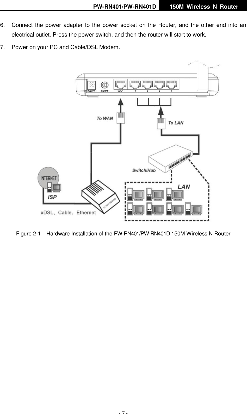
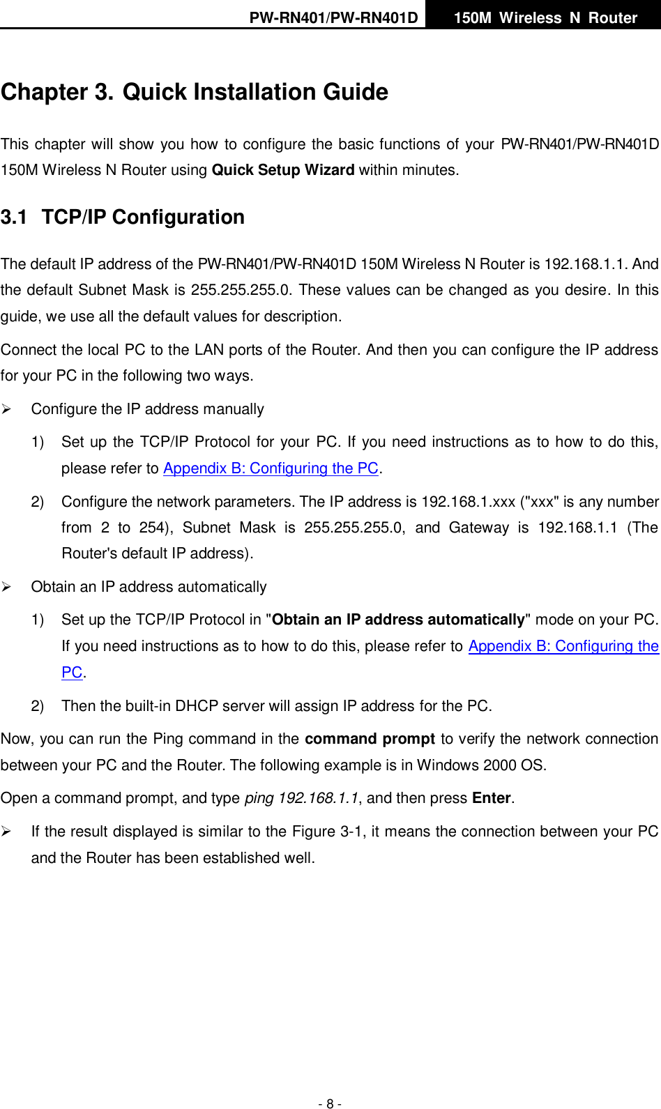
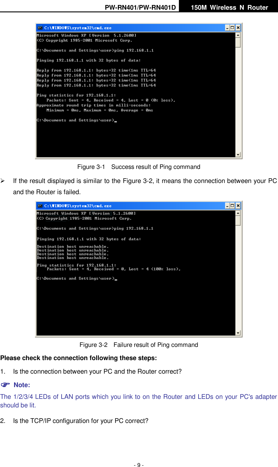
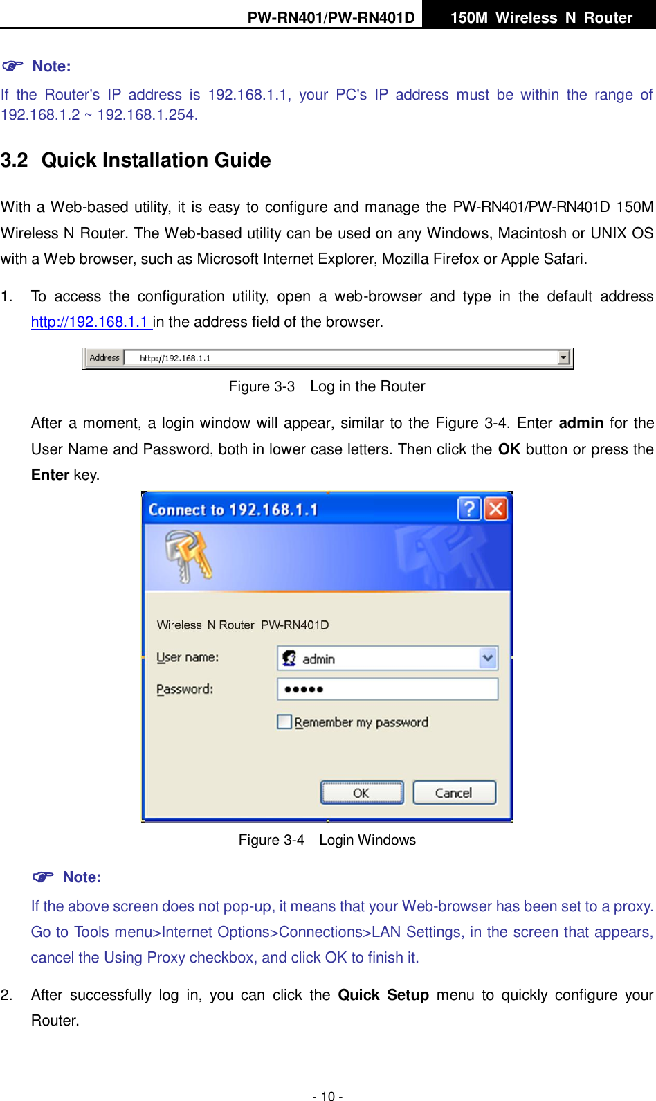
User Manual
Discussion / Help
Navigation