Proxim Wireless 815058 Outdoor Wireless Point-to-(Multi)Point System (5.8GHz) User Manual QB 8100 MP 8100 RegulatoryFlyer
Proxim Wireless Corporation Outdoor Wireless Point-to-(Multi)Point System (5.8GHz) QB 8100 MP 8100 RegulatoryFlyer
Users Manual


Tsunami QB-8100/MP-8100 Safety and Regulatory Compliance Guide
2
Copyright
© 2009 Proxim Wireless Corporation. All rights reserved. Covered by one or more of the following U.S. patents: 5,231,634; 5,875,179; 6,006,090;
5,809,060; 6,075,812; 5,077,753. This user’s guide and the software described in it are copyrighted with all rights reserved. No part of this
publication may be reproduced, transmitted, transcribed, stored in a retrieval system, or translated into any language in any form by any means
without the written permission of Proxim Wireless Corporation.
Trademarks
Tsunami, Proxim, and the Proxim logo are trademarks of Proxim Wireless Corporation. All other trademarks mentioned herein are the property of
their respective owners.
Tsunami QB-8100/MP-8100 Safety and Regulatory Compliance Guide
Version 1.1
P/N 77063, September 2009
Tsunami QB-8100/MP-8100 Safety and Regulatory Compliance Guide 3
1.1 Products covered in this guide
This document contains important safety and regulatory compliance information for the following products:
* (Stock Keeping Units)
Please see the following sections for more information:
•Safety Information (USA, Canada, & European Union)
•European Community Compliance
•Federal Communications Commission (FCC) Compliance
•Information for Professional Installers
•Regulatory Compliance Certifications Summary
IMPORTANT!
Visit http://support.proxim.com for the latest safety and regulatory compliance information for this product.
Please read this document before installing and using your product, and save these instructions.
Product Family QuickBridge SKUs*
Tsunami QB-8100 Outdoor Wireless
Point-to-Point System
QB-8150-EPR-US
QB-8100-EPA-US
QB-8150-EPR-WD
QB-8100-EPA-WD
Product Family MultiPoint SKUs*
Tsunami MP-8100 Outdoor Wireless
Point-to-MultiPoint System
MP-8100-BSU-US
MP-8100-SUA-US
MP-8150-SUR-US
MP-8100-BSU-WD
MP-8100-SUA-WD
MP-8150-SUR-WD

Tsunami QB-8100/MP-8100 Safety and Regulatory Compliance Guide 4
1.2 Safety Information (USA, Canada, & European Union)
1. These products have been evaluated to, and comply with, the U.S. and Canadian (Bi National) Standard for Safety of
Information Technology Equipment, including IEC 60950, UL certificate, Standard: UL60950-1+Part 22, UL
60950-22(UL+cUL) Outdoor.
All products are intended to be installed, used, and maintained by experienced telecommunications personnel only.
When using this device, basic safety precautions should always be followed to reduce the risk of fire, electrical shock, and
injury to persons, including the following:
WARNING: These units are intended for installation in accordance with Articles 110-18, 110-26, and 110-27, 725,
800, and 810 of the United States National Electric Code ANSINFPA 70, and per the applicable
Articles in the Canadian National Electric Code.
•Operate and install these products as described in this manual. Equipment must be installed and used in strict accordance
with the manufacturer's instructions as described in the user documentation provided.
•Installation of these products in the end use must conform to local regulations and codes.
•Products are to be used with and powered by only the power injector provided.
•A 15-amp circuit breaker is required at the power source.
WARNING: This equipment is intended to be grounded. A 10 AWG earthing conductor at a minimum is to be
used for this purpose.
•Do not connect or disconnect the power cable to the equipment when the power injector is plugged into an AC power
outlet.
•Servicing of these products should be performed only by trained personnel. Do not disassemble. By opening or removing
any covers, you may expose yourself to hazardous energy parts. Incorrect reassembly of these products can cause a
malfunction and/or electric shock when the units are subsequently used. No user serviceable parts; all repairs and service
must be handled by a qualified service center.
•Do not insert any objects of any shape or size inside these products while powered on. Object may contact hazardous
energy parts that could result in a risk of fire or personal injury.
•Do not remove or alter the Marking label provided on these products.
•To avoid the risk of electric shock from lightning, do not use these products during an electrical storm.

Tsunami QB-8100/MP-8100 Safety and Regulatory Compliance Guide 5
1.3 European Community Compliance
This device complies with the Low Voltage Directive 73/23/EEC and R&TTE Directive 1999/5/EC. Compliance with these
directives implies conformity to harmonized European standards (European Norms) that are listed on the EU Declaration of
Conformity that has been issued by Proxim Wireless Company for this device.
Countries of Operation & Conditions of Use
This device may be used in the following EU and EFTA countries: Austria, Belgium, Bulgaria, Cyprus, Czech Republic,
Denmark, Estonia, Finland, France, Germany, Greece, Hungary, Iceland, Ireland, Italy, Latvia, Liechtenstein, Lithuania,
Luxembourg, Malta, Netherlands, Norway, Poland, Portugal, Slovak Republic, Slovenia, Spain, Sweden, Switzerland and the
United Kingdom.
The professional installer must use the configuration utility provided with this device to ensure that EIRP and the channels of
operation are in conformance with the spectrum usage rules for EU and EFTA countries as described below.
5 GHz Operation
This device requires professional installer to properly enter the current country of operation for the 5 GHz band as described
in the Installation and Management Guide, before operating this device.
This device employs a radar detection feature required for European Community and EFTA country operation in the 5 GHz
band. This feature is automatically enabled when the country of operation is correctly configured for any European
Community or EFTA country. The presence of nearby radar operation may result in temporary interruption of operation of this
device. The radar detection feature will automatically restart operation on a channel free of radar.
Transmit Power Control (TPC) for 5 GHz operation
This device employs Transmit Power Control (TPC) to reduce the potential for interference to other communication systems
operating in the 5 GHz frequency bands. The TPC feature implemented must be configured by the professional installer when
operating in any European Community or EFTA country in accordance with European regulatory requirements for Transmit
Power control.
NOTE: The TPC procedure should be repeated when relocating this wireless device within the current wireless network
or to a wireless network in a new location.

Tsunami QB-8100/MP-8100 Safety and Regulatory Compliance Guide 6
1.4 Federal Communications Commission (FCC) Compliance
These products operate at the following frequencies in compliance with Part 15 of the FCC rules:
•Model QB-8100-EPA: 5 GHz
•Model QB-8150-EPR: 5 GHz
•Model MP-8100-BSU: 5 GHz
•Model MP-8100-SUA: 5 GHz
•Model MP-8150-SUR: 5 GHz
Operation is subject to the following two conditions: 1) this device may not cause harmful interference, and 2) this device
must accept any interference received, including interference that may cause undesired operation.
To comply with the FCC radio frequency exposure requirements, the following antenna installation and device operating
configurations must be satisfied:
•Product models using external antennas require professional installation. The antennas used for professional
installation must be fixed-mounted on indoor/outdoor permanent structures with a separation distance from all
persons more than 150 cm (approximately 60 inches) for panel antennas, more than 40 cm (approximately 16 inches)
for sector antennas.
•Antennas must not be co-located and must not operate in conjunction with any other antenna or transmitter.
NOTE: This equipment has been tested and found to comply with the limits for a Class B digital device, pursuant to
part 15 of the FCC Rules. These limits are designed to provide reasonable protection against harmful interference in a
residential installation. This equipment generates, uses and can radiate radio frequency energy and, if not installed
and used in accordance with the instructions, may cause harmful interference to radio communications. However,
there is no guarantee that interference will not occur in a particular installation. If this equipment does cause harmful
interference to radio or television reception, which can be determined by turning the equipment off and on, the user
is encouraged to try to correct the interference by one or more of the following measures:
– Reorient or relocate the receiving antenna.
– Increase the separation between the equipment and receiver.
– Connect the equipment into an outlet on a circuit different from that to which the receiver is connected.
– Consult the dealer or an experienced radio/TV technician for help.
1.4.1 Modifications
The FCC requires the user to be notified that any changes or modifications to this device that are not expressly approved by
the manufacturer may void the user’s authority to operate the equipment. The correction of interference caused by
unauthorized modification, substitution or attachment will be the responsibility of the user. The manufacturer and its
authorized resellers or distributors are not liable for any damage or violation of government regulations that may arise from
failing to comply with these guidelines.
1.4.2 Warnings
This equipment generates, uses, and can radiate radio frequency energy; and, if not installed and used in accordance with the
instructions, may cause harmful interference to radio communications. However, there is no guarantee that interference will
not occur in a particular installation. If this equipment does cause harmful interference to radio or television reception, which
can be determined by turning the equipment off and on, the user is encouraged to try and correct the interference by one or
more of the following measures:
•Reorient or relocate the receiving antenna
•Increase the distance between the equipment and the receiver

Tsunami QB-8100/MP-8100 Safety and Regulatory Compliance Guide 7
•Connect the equipment to an AC outlet on a circuit different from that to which the receiver is connected
•Consult the dealer or an experienced radio/TV technician for help
In some situations or environments, the use of wireless devices may be restricted by the proprietor of the building or
responsible representatives of the organization. These situations may, for example, include the use of wireless equipment on
board airplanes, or in any other environment where the risk of interference to other devices or services is perceived or
identified as harmful.
If you are uncertain of the policy that applies on the use of wireless equipment in a specific organization or environment (such
as airports), you are encouraged to ask for authorization to use this device prior to turning on the equipment.
WARNING: Modification of this device to receive cellular Radio Telephone service signals is prohibited under FCC
Rules and Federal Law.
FCC NOTICE: To comply with FCC part 15 rules in the United States, the system must be professionally installed
to ensure compliance with the Part 15 certification. It is the responsibility of the operator and
professional installer to ensure that only certified systems are deployed in the United States. The use
of the system in any other combination (such as co-located antennas transmitting the same
information) is expressly forbidden.
1.5 Information for Professional Installers
All products must be professionally installed, and the transmit power of the system must be adjusted by the professional
installers to ensure that the system EIRP is in compliance with the limit specified by the regulatory authority of the country of
application.
See the following sections for more information:
•Adjusting Tx Output Power
•Antenna Types and Maximum Gain
1.5.1 Adjusting Tx Output Power
NOTE: When the system is set to transmit at the maximum power, professional installers must ensure that the
maximum EIRP limit is not exceeded. To achieve this, they may have to add attenuation between the device and the
antenna when a high gain antenna is used.
Use the following formula in combination with the table of EIRP limits in US and EU countries to calculate system transmit
power (based on EIRP limits) of these countries:
Tx Power (dBm) = EIRP Limit (dBm) + FL (dB) – G (dB)
where:
Tx Power = Output power measured at the antenna input
EIRP Limit = EIRP limits specified below
FL = Feeder loss including loss of connectors
G = Antenna Gain
Transmit output power can be reduced by using the Transmit Power Control (TPC) field on the Configure > Interfaces >
Wireless screen. Refer to the Installation and Management Guide for more information.

Tsunami QB-8100/MP-8100 Safety and Regulatory Compliance Guide 8
WARNING: You must add external attenuation pad if calculated EIRP is over the limit.
1.5.2 Antenna Types and Maximum Gain
Professional installers should select only the antenna listed in the Tsunami QB-8100/MP-8100 Recommended Antennas
Guide, with gain not exceeding the listed maximum gain for each type.
Band EIRP Limit (dBm)
USA and Canada EU
5.725 - 5.850 GHz 30 (Point-to-Multipoint) Operation is not allowed
No limit (Point-to-Point)
Frequency Band Antenna Type Maximum Gain (dBi)
5 GHz Panel 30
Sector 17

Tsunami QB-8100/MP-8100 Safety and Regulatory Compliance Guide 9
1.6 Regulatory Compliance Certifications Summary
1.6.1 Model QB-8100-EPA
1.6.2 Model QB-8150-EPR
1.6.3 Model MP-8100-BSU
1.6.4 Model MP-8100-SUA
Country Certification/Reference No.
USA FCC ID: HZB815058
Canada IC: 1856A-PROXMB82
Country Certification/Reference No.
USA FCC ID: HZB815058
Canada IC: 1856A-PROXMB82
Country Certification/Reference No.
USA FCC ID: HZB815058
Canada IC: 1856A-PROXMB82
Country Certification/Reference No.
USA FCC ID: HZB815058
Canada IC: 1856A-PROXMB82
10
1.6.5 Model MP-8150-SUR
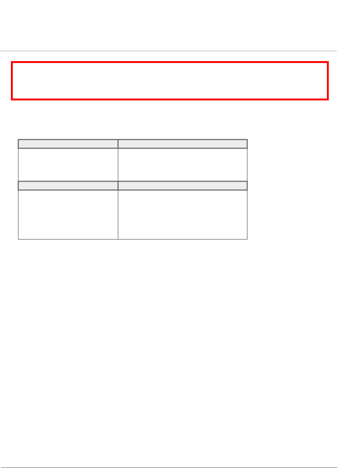
1.7 Unit’s Hardware Description
NOTE: In the connectorized version, if you use Single Polarization antenna, always use the antenna port
A1. If you use Dual Polarization antenna, use the antenna port A1 and A3.
Country Certification/Reference No.
USA FCC ID: HZB815058
Canada IC: 1856A-PROXMB82
11
1.8 Installation Procedure
This section describes the procedures to install and mount the unit and to align the antenna. The installation procedure does
not include information on the mounting and connection of external antennas.
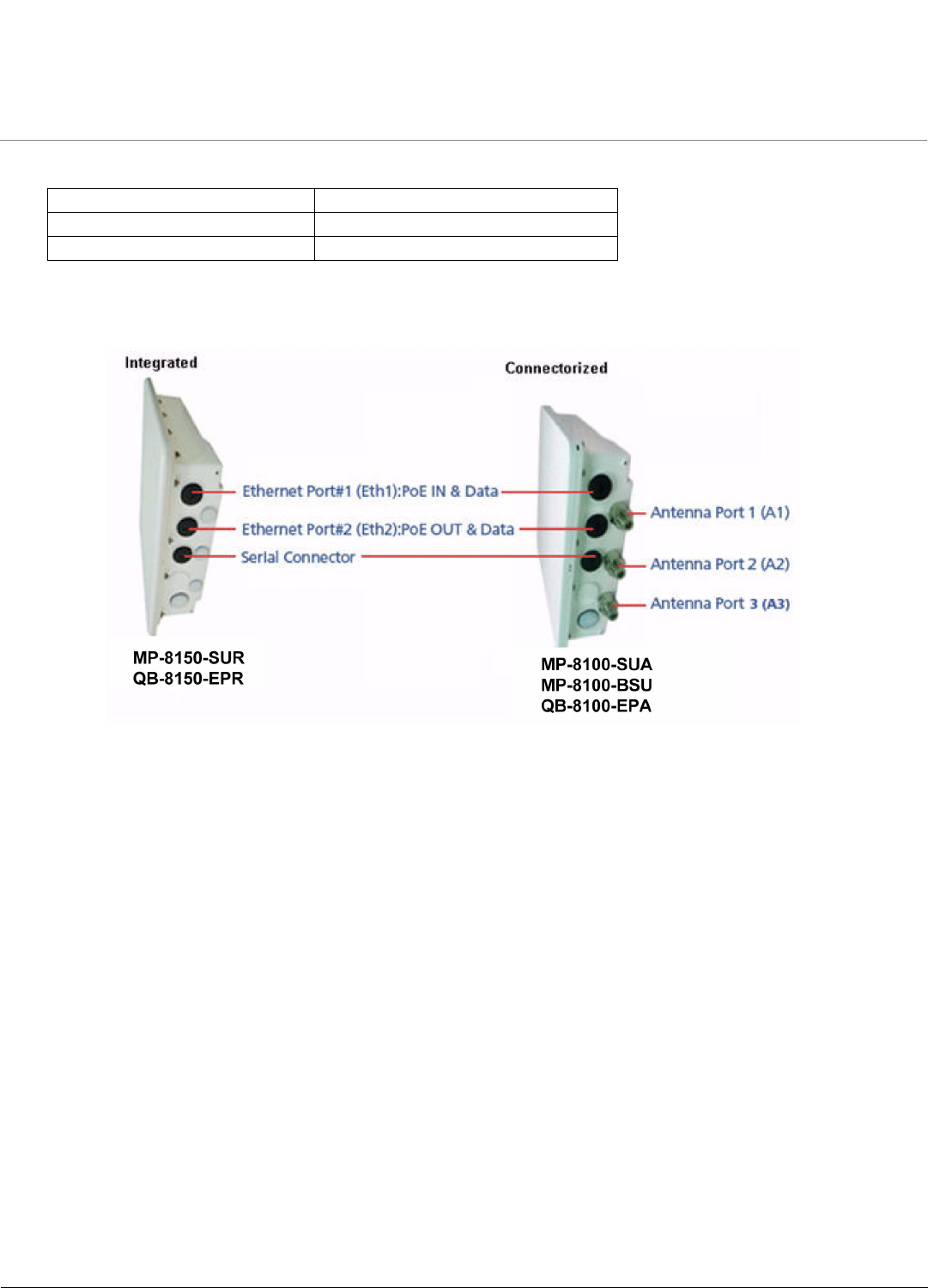
Assemble the Mounting Hardware
Attach the mounting plate (A) using the provided screws and washers (Torque 9 N.m/75 in-lbs), such that the unit’s antenna will be vertically and
horizontally polarized when mounted. Attach the extension arm (B) to mounting piece (A) with the screw, nut, and washers provided, as shown below.
The extension arm gives the unit more possible tilt, letting you adjust for azimuth or elevation over a larger angle. Attach the mounting bracket (C) to
extension arm (B) with the screw, nut, and washers provided. Tighten the assembly (Torque 15 N•m/130 in-lbs). The last figure shows the full assembly
attached to the unit.
Note: This figure is for illustration only. Units should be mounted in square position with connectors facing downward.
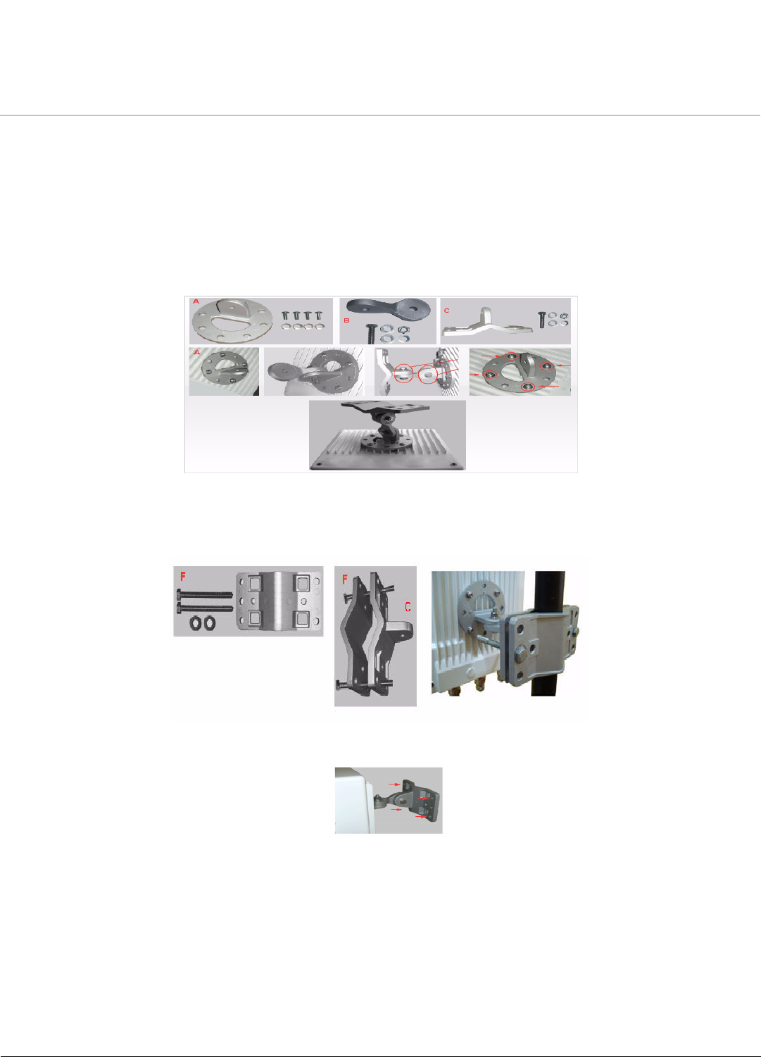
Mount the Unit
1. To pole-mount the unit, insert the provided screws through bracket (F). Fasten around the pole to bracket (C) and secure (Torque 11 N.m/100
in-lbs).
2. To wall-mount the unit, mount the bracket to a wall using 4 screws (not provided), as shown below.
Plug in the Cables
Note: Unscrew the sealing cap for installation of the cable.
1. Plug one end of the Cat5e/Cat6 cable (Eth1) into the Ethernet (RJ45) jack of the Eth1 interface inside the enclosure. Plugging in the second
Cat5e/Cat6 cable to Eth2 interface is optional. Ensure that the cable connector is latched securely and the Toroids are fixed on the cable. You can
hear a click sound when the cable connector latches into the jack, then tighten the sealing nut by hand.
2. Plug the Serial cable into the serial RJ11 telephone jack inside the enclosure. (leftmost cable in the picture below) Tighten the sealing nut by hand.
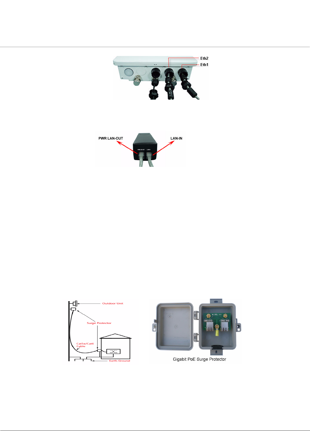
12
3. Connect the other end of the first CAT5e/Cat6 cable (Eth1) to the “PWR LAN-OUT” port on the power injector.
Warning: A tension of 48 VDC (15 W average) is present on the second ethernet port (Eth2). Make sure the connected device can support
this tension on its ethernet port.
Warning: Connect network devices only into the LAN-IN port of the Power injector. The PWR LAN-OUT port is meant to power the
QBMP-8100 unit.
4. To connect the QBMP-8100 unit through a hub or a switch to a PC, connect an Ethernet cable between the network interface card in the PC and
the hub and between the hub and the RJ45 “LAN-IN” port on the PoE adapter.
5. To connect the QBMP-8100 unit directly to a PC, connect an Ethernet cable between the network interface card in the PC and the RJ45 “LAN-IN”
port on the power injector.
Connect the Antenna (Connectorized Version Only)
Connect the antenna with N-male cables to the antenna connectors on the device.
Note: Write down the ports to which you have connected the antenna. This will be useful during the configuration of MIMO
parameters.
Units with integrated antennas must always be mounted in square position to achieve Horizontal and Vertical+45 degree and -45 degree polarization.
Install Surge Protector
Proxim recommends two approved lightning surge protectors to be installed, one near to the device (supplied with the product package) and the other
near to the building ingress point.
Perform the following steps to ensure proper surge protection:
1. Mount the provided surge protector near the outdoor equipment and use 10 AWG or larger wire to connect the protector’s ground lug to the
appropriate mounting ground point. The outdoor equipment and co-located surge protector should have a common grounding point using the
shortest possible grounding cable
2. Mount a second surge protector near the building ingress and use 10 AWG or larger wire to connect the protector’s ground lug to earth ground as
shown in the following figure.
Note: Use Outdoor-rated, UV protected, shielded Cat5e/Cat6 cable for the following.
3. Connect an RJ45 terminated cable between the indoor equipment and to the port on the surge protector at the building ingress.
4. Connect a short RJ45 terminated cable between the outdoor equipment and the port on the co-located surge protector.
5. Connect an RJ45 terminated cable between the two surge protectors on their remaining ports.
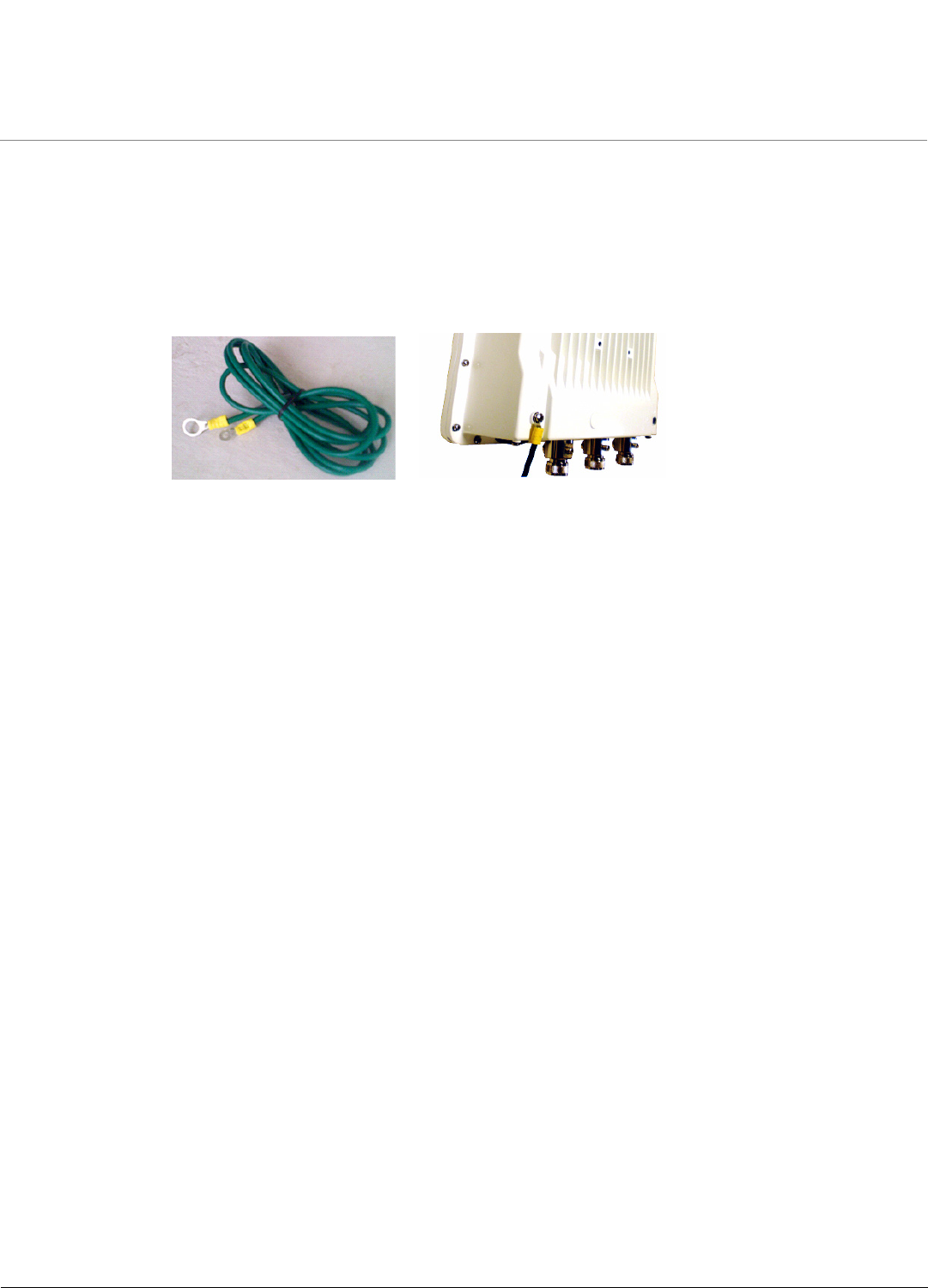
Ground the Unit
To ensure proper grounding, use either of the ground points which are situated at the bottom corners of the unit and the grounding screw provided to
attach a ground wire of at least 10 AWG stranded to the unit. It is important that the following ground guidelines are followed during installations:
13
1. Cut any extra ground wire length when finished connecting it to the single point earth ground.
2. Avoid sharp bends and never loop or coil up the ground wire, always connect it straight to ground.
3. A good earth ground impedance is less than 1.0 ohm.
4. Measure ground impedance at the point where the protector ground wire is connected and not at the ground rod.
5. Connect the protector ground wire and equipment ground (both power ground and telecomm ground) to a single common ground.
6. Make sure all connections are fastened securely and are tight.
7. Never install during a storm and always follow your local safety codes.
Connect the grounding wire, which is supplied with the product package, to the grounding lug as shown below:
.
Power on the Unit
Plug in the power cord into a power outlet after having connected the Power Injector and the Radio device using Cat5e/Cat6 cable. There is no ON/OFF
switch on the unit. To disconnect power, unplug the RJ45 connector from the “PWR LAN-OUT” port on the power injector.