Proxim Wireless A09UCF UNII/ISM Radio Network Equipment User Manual Chapter 1 Overview
Proxim Wireless Corporation UNII/ISM Radio Network Equipment Chapter 1 Overview
UserManual.wiki
>
Proxim Wireless
>
A09UCF User Manual
>
Users Manual I
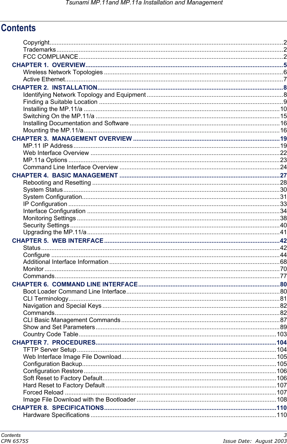
Contents
1.
Users Manual I
2.
Users Manual II
3.
Professional Installation Manual
4.
Revised Professional Installation Manual
Users Manual I
Navigation menu
Upload a User Manual
Namespaces
Wiki Guide
HTML
PDF
Info
Views
User Manual
Discussion / Help
Navigation