Proxim Wireless AP700 Wireless Access Device User Manual APs UG

Proxim Wireless Corporation Wireless Access Device APs UG

Users Manual 2 of 3
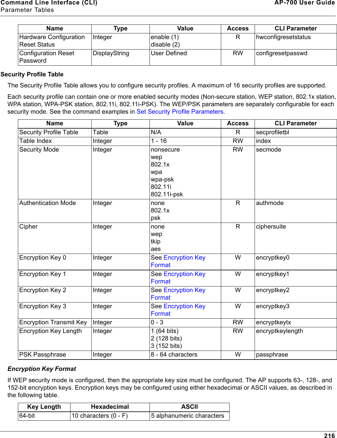
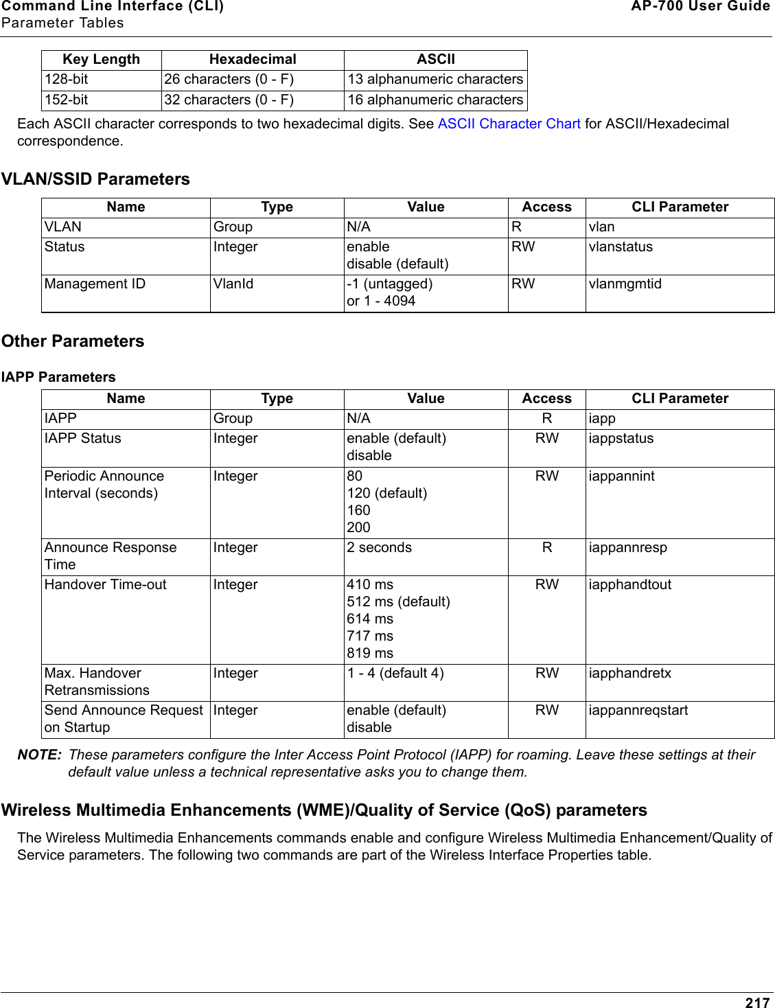
Advanced Configuration AP-700 User GuideSSID/VLAN/Security116— For 64-bit encryption, an encryption key is 10 hexadecimal characters (0-9 and A-F) or 5 ASCII characters (see ASCII Character Chart).— For 128-bit encryption, an encryption key is 26 hexadecimal characters or 13 ASCII characters.— For 152-bit encryption, an encryption key is 32 hexadecimal characters or 16 ASCII characters.• Encryption Transmit Key: select Key 0, Key 1, Key 2, or Key 3NOTE: When VLAN tagging is enabled, only Key 0 can be configured.•802.1x Station:• Authentication Mode: 802.1x• Cipher: WEP• Encryption Key Length: 64 or 128 Bits. — If 802.1x is enabled simultaneously with WEP, the 802.1x Station’s encryption key length is determined by the WEP encryption key. •WPA Station:• Authentication Mode: 802.1x• Cipher: TKIP•WPA-PSK Station:• Authentication Mode: PSK• Cipher: TKIP• PSK Passphrase: an 8-63 character user-defined phrase. It is recommended a passphrase of at least 13 characters, including both letters and numbers, and upper and lower case characters, be used to ensure that the generated key cannot be easily deciphered by network infiltrators.•802.11i Station:• Authentication Mode: 802.1x• Cipher: CCMP based on AES•802.11i-PSK Station:• Authentication Mode: PSK• Cipher: CCMP based on AES• PSK Passphrase: an 8-63 character user-defined phrase. It is recommended a passphrase of at least 13 characters, including both letters and numbers, and upper and lower case characters, to ensure that the generated key cannot be easily deciphered by network infiltrators.5. When finished configuring all parameters, click OK.6. If you selected a Security Mode of 802.1x Station, WPA Station, or 802.11i Station, you must configure a RADIUS 802.1x/EAP server. See the Configuring Radius Profiles section. Security Profile 1 will be used by default for all wireless interfaces.7. Reboot the AP.
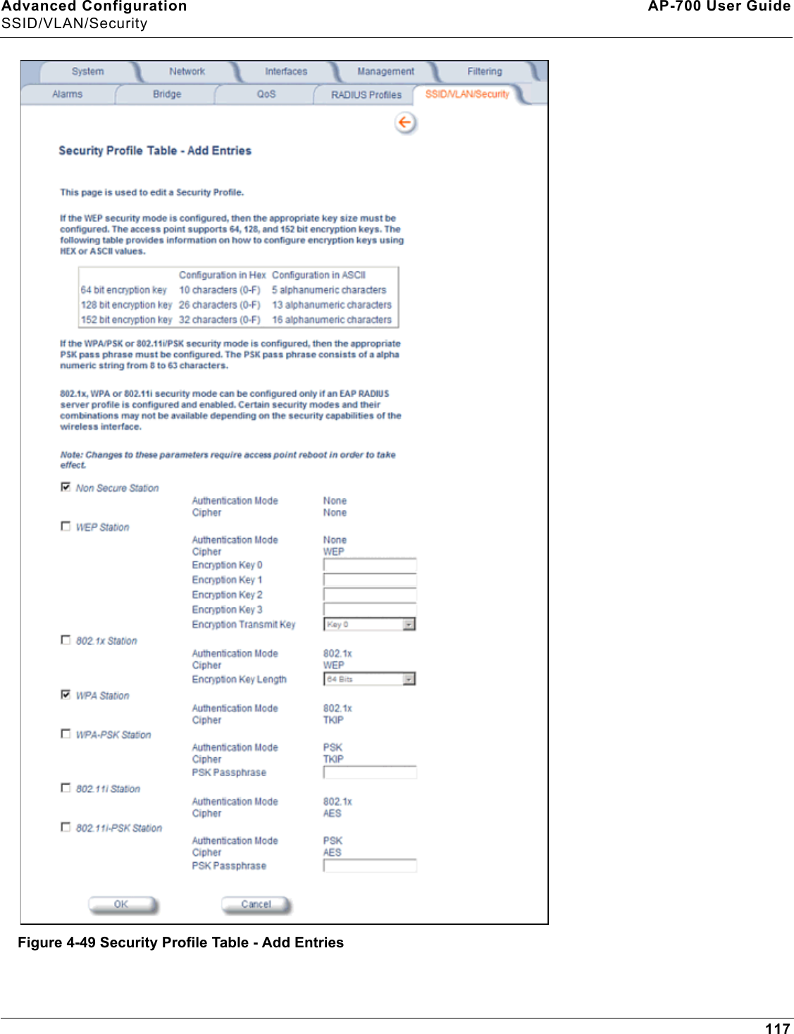
Advanced Configuration AP-700 User GuideSSID/VLAN/Security117Figure 4-49 Security Profile Table - Add Entries
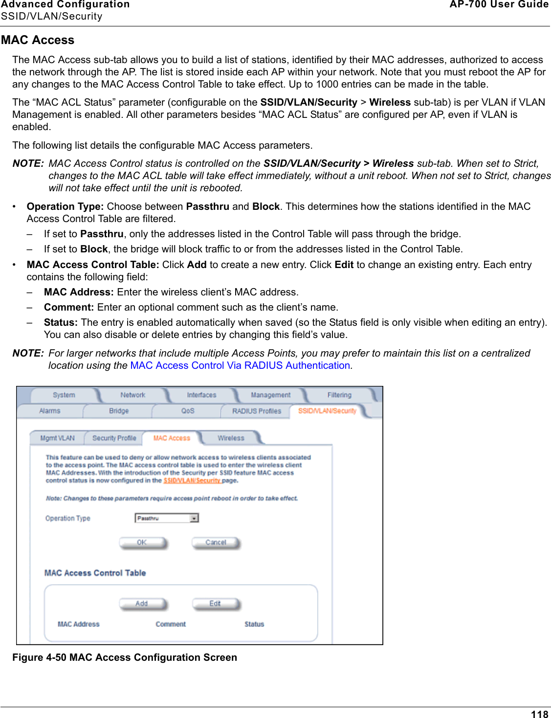
Advanced Configuration AP-700 User GuideSSID/VLAN/Security118MAC AccessThe MAC Access sub-tab allows you to build a list of stations, identified by their MAC addresses, authorized to access the network through the AP. The list is stored inside each AP within your network. Note that you must reboot the AP for any changes to the MAC Access Control Table to take effect. Up to 1000 entries can be made in the table.The “MAC ACL Status” parameter (configurable on the SSID/VLAN/Security > Wireless sub-tab) is per VLAN if VLAN Management is enabled. All other parameters besides “MAC ACL Status” are configured per AP, even if VLAN is enabled.The following list details the configurable MAC Access parameters.NOTE: MAC Access Control status is controlled on the SSID/VLAN/Security > Wireless sub-tab. When set to Strict, changes to the MAC ACL table will take effect immediately, without a unit reboot. When not set to Strict, changes will not take effect until the unit is rebooted. •Operation Type: Choose between Passthru and Block. This determines how the stations identified in the MAC Access Control Table are filtered.– If set to Passthru, only the addresses listed in the Control Table will pass through the bridge. – If set to Block, the bridge will block traffic to or from the addresses listed in the Control Table.•MAC Access Control Table: Click Add to create a new entry. Click Edit to change an existing entry. Each entry contains the following field:–MAC Address: Enter the wireless client’s MAC address.–Comment: Enter an optional comment such as the client’s name.–Status: The entry is enabled automatically when saved (so the Status field is only visible when editing an entry). You can also disable or delete entries by changing this field’s value.NOTE: For larger networks that include multiple Access Points, you may prefer to maintain this list on a centralized location using the MAC Access Control Via RADIUS Authentication.Figure 4-50 MAC Access Configuration Screen
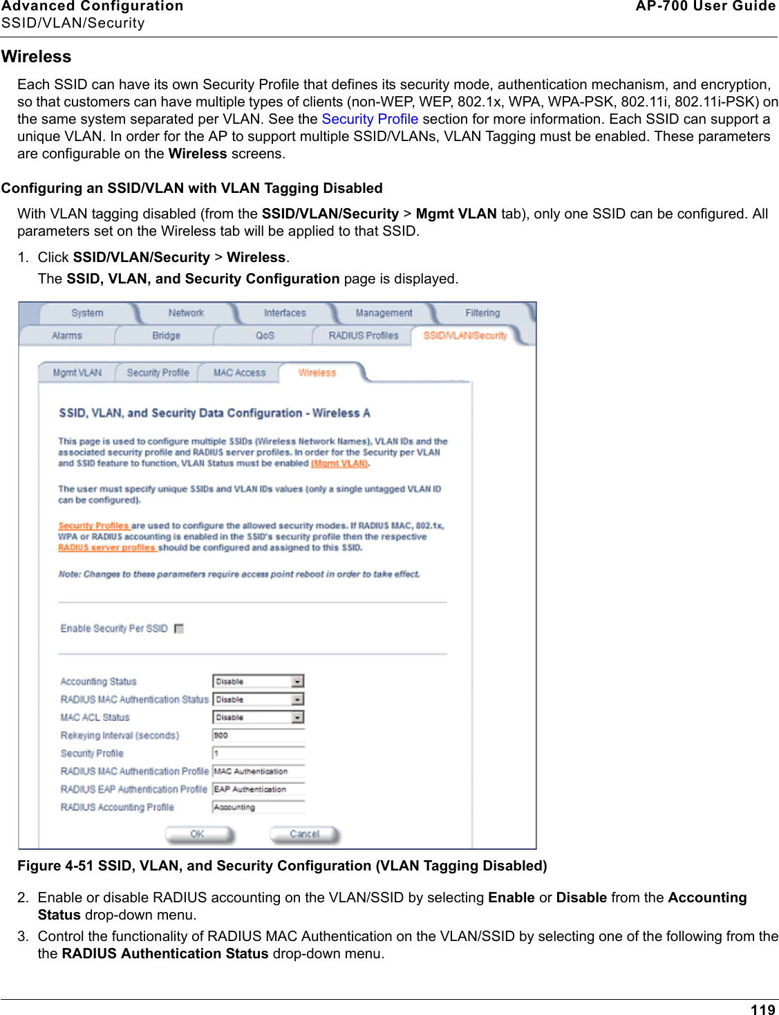
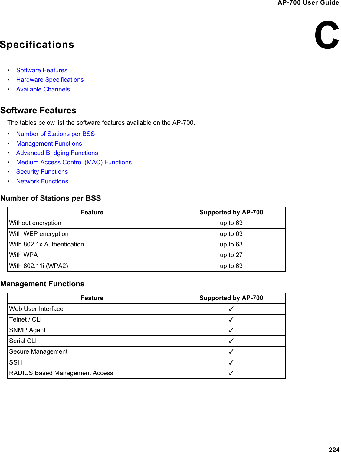
Advanced Configuration AP-700 User GuideSSID/VLAN/Security119WirelessEach SSID can have its own Security Profile that defines its security mode, authentication mechanism, and encryption, so that customers can have multiple types of clients (non-WEP, WEP, 802.1x, WPA, WPA-PSK, 802.11i, 802.11i-PSK) on the same system separated per VLAN. See the Security Profile section for more information. Each SSID can support a unique VLAN. In order for the AP to support multiple SSID/VLANs, VLAN Tagging must be enabled. These parameters are configurable on the Wireless screens.Configuring an SSID/VLAN with VLAN Tagging DisabledWith VLAN tagging disabled (from the SSID/VLAN/Security > Mgmt VLAN tab), only one SSID can be configured. All parameters set on the Wireless tab will be applied to that SSID.1. Click SSID/VLAN/Security > Wireless. The SSID, VLAN, and Security Configuration page is displayed. Figure 4-51 SSID, VLAN, and Security Configuration (VLAN Tagging Disabled)2. Enable or disable RADIUS accounting on the VLAN/SSID by selecting Enable or Disable from the Accounting Status drop-down menu.3. Control the functionality of RADIUS MAC Authentication on the VLAN/SSID by selecting one of the following from the the RADIUS Authentication Status drop-down menu.
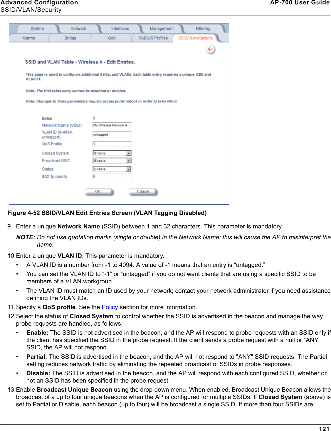
Advanced Configuration AP-700 User GuideSSID/VLAN/Security120•Enable: MAC addresses in the MAC Access Control List stored on the RADIUS server are blocked or allowed, based on the MAC ACL settings. If a higher priority authentication protocol is also enabled, the higher-priority settings will override the MAC ACL settings. See Authentication Protocol Hierarchy.•Disable: RADIUS MAC ACL settings are disabled.•Strict: RADIUS MAC ACL settings are enabled. If a higher-priority authentication protocol is also enabled, RADIUS MAC ACL settings will be applied in addition to the higher priority authentication protocol settings. See Authentication Protocol Hierarchy. 4. Control the functionality of the MAC Access Control List on the VLAN/SSID by selecting one of the following from the MAC ACL Status drop-down menu:•Enable: MAC addresses in the MAC Access Control List are blocked or allowed, based on the MAC ACL settings. If a higher priority authentication protocol is also enabled, the higher-priority settings will override the MAC ACL settings. See Authentication Protocol Hierarchy.•Disable: MAC ACL settings are disabled.•Strict: MAC ACL settings are enabled. If a higher-priority authentication protocol is also enabled, MAC ACL settings will be applied in addition to the higher priority authentication protocol settings. See Authentication Protocol Hierarchy. When MAC ACL Status is set to Strict, changes to the MAC ACL table (configured on the MAC Access page) will take effect without a device reboot.5. Enter Rekeying Interval in seconds (between 300 and 65525). When set to 0, this parameter is disabled. The default is 900 seconds.6. Enter the Security Profile used by the VLAN in the Security Profile field. See the Security Profile section for more information.7. Define the RADIUS Server Profile Configuration for the VLAN/SSID:• RADIUS MAC Authentication Profile• RADIUS EAP Authentication Profile• RADIUS Accounting ProfileIf 802.1x, WPA, or 802.11i security mode is used, the RADIUS EAP Authentication Profile must have a value.A RADIUS Server Profile for authentication for each VLAN shall be configured as part of the configuration options for that VLAN. RADIUS profiles are independent of VLANs. The user can define any profile to be the default and associate all VLANs to that profile. Four profiles are created by default, “MAC Authentication”, “EAP Authentication”, Accounting”, and “Management”8. If desired, scroll down to the scroll down to the SSID and VLAN Table and click Edit to modify the Network Name, VLAN ID, or QoS profile of the SSID/VLAN. NOTE: Because VLAN tagging is disabled, attempting to add a new SSID/VLAN will produce an error message.The Edit Entries screen will be displayed. See Figure 4-52.
Advanced Configuration AP-700 User GuideSSID/VLAN/Security121 Figure 4-52 SSID/VLAN Edit Entries Screen (VLAN Tagging Disabled)9. Enter a unique Network Name (SSID) between 1 and 32 characters. This parameter is mandatory.NOTE: Do not use quotation marks (single or double) in the Network Name; this will cause the AP to misinterpret the name. 10.Enter a unique VLAN ID. This parameter is mandatory.• A VLAN ID is a number from -1 to 4094. A value of -1 means that an entry is “untagged.”• You can set the VLAN ID to “-1” or “untagged” if you do not want clients that are using a specific SSID to be members of a VLAN workgroup.• The VLAN ID must match an ID used by your network; contact your network administrator if you need assistance defining the VLAN IDs.11. Specify a QoS profile. See the Policy section for more information. 12.Select the status of Closed System to control whether the SSID is advertised in the beacon and manage the way probe requests are handled, as follows:•Enable: The SSID is not advertised in the beacon, and the AP will respond to probe requests with an SSID only if the client has specified the SSID in the probe request. If the client sends a probe request with a null or “ANY” SSID, the AP will not respond. •Partial: The SSID is advertised in the beacon, and the AP will not respond to "ANY" SSID requests. The Partial setting reduces network traffic by eliminating the repeated broadcast of SSIDs in probe responses. •Disable: The SSID is advertised in the beacon, and the AP will respond with each configured SSID, whether or not an SSID has been specified in the probe request.13.Enable Broadcast Unique Beacon using the drop-down menu. When enabled, Broadcast Unique Beacon allows the broadcast of a up to four unique beacons when the AP is configured for multiple SSIDs. If Closed System (above) is set to Partial or Disable, each beacon (up to four) will be broadcast a single SSID. If more than four SSIDs are
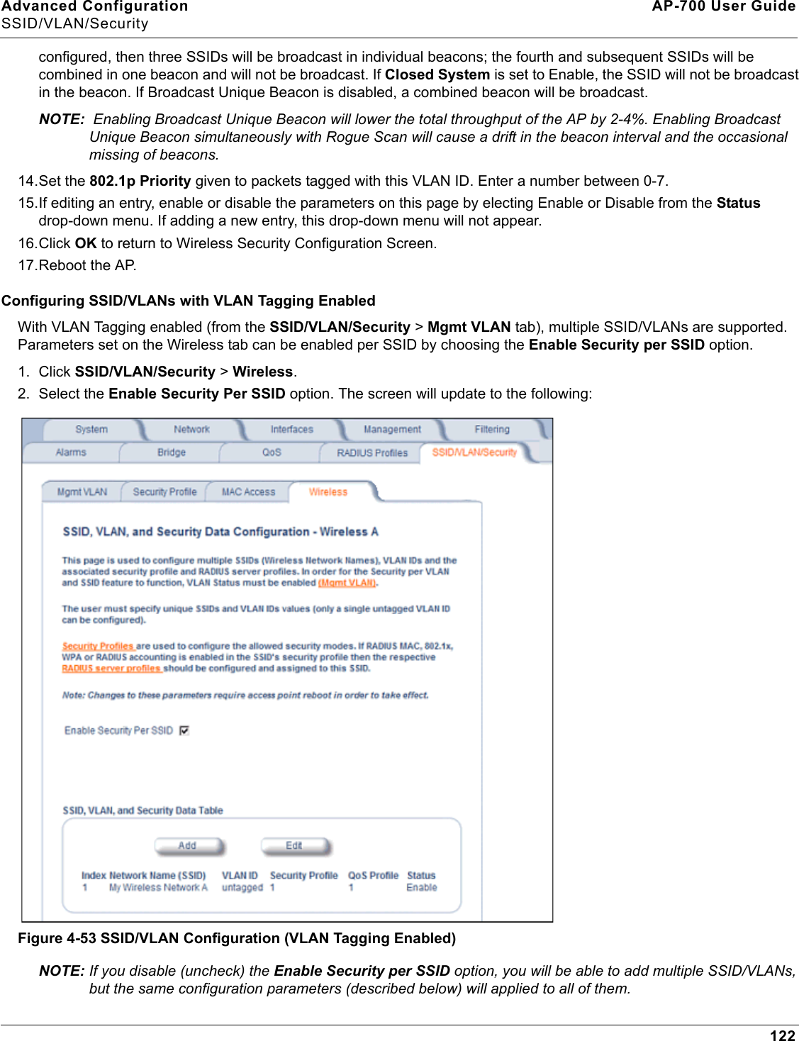
Advanced Configuration AP-700 User GuideSSID/VLAN/Security122configured, then three SSIDs will be broadcast in individual beacons; the fourth and subsequent SSIDs will be combined in one beacon and will not be broadcast. If Closed System is set to Enable, the SSID will not be broadcast in the beacon. If Broadcast Unique Beacon is disabled, a combined beacon will be broadcast. NOTE:  Enabling Broadcast Unique Beacon will lower the total throughput of the AP by 2-4%. Enabling Broadcast Unique Beacon simultaneously with Rogue Scan will cause a drift in the beacon interval and the occasional missing of beacons.14.Set the 802.1p Priority given to packets tagged with this VLAN ID. Enter a number between 0-7.15.If editing an entry, enable or disable the parameters on this page by electing Enable or Disable from the Status drop-down menu. If adding a new entry, this drop-down menu will not appear.16.Click OK to return to Wireless Security Configuration Screen. 17.Reboot the AP.Configuring SSID/VLANs with VLAN Tagging EnabledWith VLAN Tagging enabled (from the SSID/VLAN/Security > Mgmt VLAN tab), multiple SSID/VLANs are supported. Parameters set on the Wireless tab can be enabled per SSID by choosing the Enable Security per SSID option.1. Click SSID/VLAN/Security > Wireless. 2. Select the Enable Security Per SSID option. The screen will update to the following: Figure 4-53 SSID/VLAN Configuration (VLAN Tagging Enabled)NOTE: If you disable (uncheck) the Enable Security per SSID option, you will be able to add multiple SSID/VLANs, but the same configuration parameters (described below) will applied to all of them.
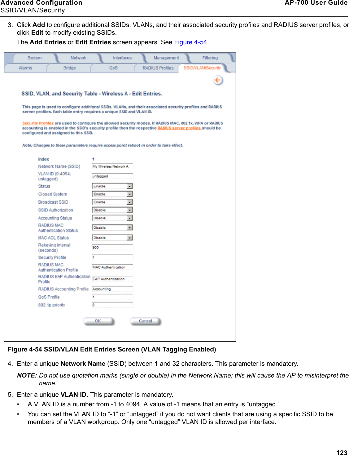
Advanced Configuration AP-700 User GuideSSID/VLAN/Security1233. Click Add to configure additional SSIDs, VLANs, and their associated security profiles and RADIUS server profiles, or click Edit to modify existing SSIDs.The Add Entries or Edit Entries screen appears. See Figure 4-54. Figure 4-54 SSID/VLAN Edit Entries Screen (VLAN Tagging Enabled)4. Enter a unique Network Name (SSID) between 1 and 32 characters. This parameter is mandatory.NOTE: Do not use quotation marks (single or double) in the Network Name; this will cause the AP to misinterpret the name.5. Enter a unique VLAN ID. This parameter is mandatory.• A VLAN ID is a number from -1 to 4094. A value of -1 means that an entry is “untagged.”• You can set the VLAN ID to “-1” or “untagged” if you do not want clients that are using a specific SSID to be members of a VLAN workgroup. Only one “untagged” VLAN ID is allowed per interface.
Advanced Configuration AP-700 User GuideSSID/VLAN/Security124• The VLAN ID must match an ID used by your network; contact your network administrator if you need assistance defining the VLAN IDs.6. Select the status of Closed System to control whether the SSID is advertised in the beacon and manage the way probe requests are handled, as follows:•Enable: The SSID is not advertised in the beacon, and the AP will respond to probe requests with an SSID only if the client has specified the SSID in the probe request. If the client sends a probe request with a null or “ANY” SSID, the AP will not respond. •Partial: The SSID is advertised in the beacon, and the AP will not respond to "ANY" SSID requests. The Partial setting reduces network traffic by eliminating the repeated broadcast of SSIDs in probe responses. •Disable: The SSID is advertised in the beacon, and the AP will respond with each configured SSID, whether or not an SSID has been specified in the probe request.7. Enable Broadcast Unique Beacon using the drop-down menu. When enabled, Broadcast Unique Beacon allows the broadcast of a up to four unique beacons when the AP is configured for multiple SSIDs. If Closed System (above) is set to Partial or Disable, each beacon (up to four) will be broadcast a single SSID. If more than four SSIDs are configured, then three SSIDs will be broadcast in individual beacons; the fourth and subsequent SSIDs will be combined in one beacon and will not be broadcast. If Closed System is set to Enable, the SSID will not be broadcast in the beacon. If Broadcast Unique Beacon is disabled, a combined beacon will be broadcast. NOTE:  Enabling Broadcast Unique Beacon will lower the throughput of the AP by 2-4%. Enabling Broadcast Unique Beacon simultaneously with Rogue Scan will cause a drift in the beacon interval and the occasional missing of beacons.8. Enable or disable the SSID Authorization status from the drop-down menu. SSID Authorization is the RADIUS-based authorization of the SSID for a particular client. The authorized SSIDs are sent as the tunnel attributes.9. Enable or disable RADIUS accounting on the VLAN/SSID under the Accounting Status drop-down menu.10.Enable or disable RADIUS MAC authentication status on the VLAN/SSID under the RADIUS Authentication Status drop-down menu.11.Enable or disable MAC Access Control List status on the VLAN/SSID under the MAC ACL Status drop-down menu.12.Enter the Rekeying Interval in seconds (between 300 and 65525). When set to 0, this parameter is disabled. The default is 900 seconds.13.Enter the Security Profile used by the VLAN in the Security Profile field.NOTE: If you have two or more SSIDs per interface using a Security Profile with a security mode of Non Secure, be aware that security being applied in the VLAN is not being applied in the wireless network.14.Define the RADIUS Server Profile Configuration for the VLAN/SSID:• RADIUS MAC Authentication Profile• RADIUS EAP Authentication Profile• RADIUS Accounting ProfileIf 802.1x, WPA, or 802.11i security mode is used, the RADIUS EAP Authentication Profile must have a value.A RADIUS Server Profile for authentication for each VLAN shall be configured as part of the configuration options for that VLAN. RADIUS profiles are independent of VLANs. The user can define any profile to be the default and associate all VLANs to that profile. Four profiles are created by default, “MAC Authentication”, “EAP Authentication”, Accounting”, and “Management”.15.Specify a QoS Profile. See the Policy section for more information. 16.Set the 802.1p Priority given to packets tagged with this VLAN ID. Enter a number between 0-7.17.If editing an entry, enable or disable the parameters on this page using Status drop-down menu. If adding a new entry, this drop-down menu will not appear.18.Reboot the AP.
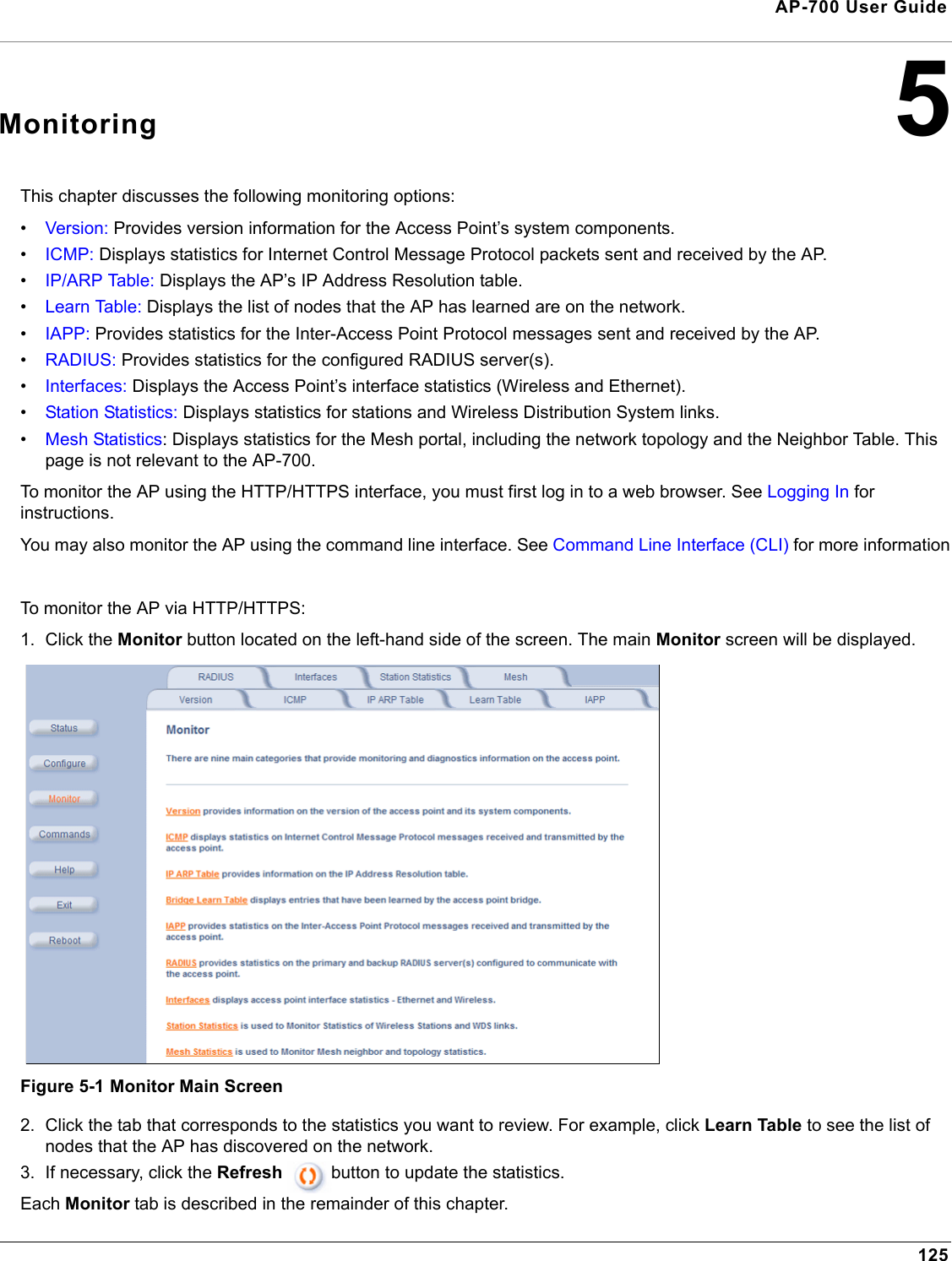
125AP-700 User Guide5MonitoringThis chapter discusses the following monitoring options:•Version: Provides version information for the Access Point’s system components.•ICMP: Displays statistics for Internet Control Message Protocol packets sent and received by the AP.•IP/ARP Table: Displays the AP’s IP Address Resolution table.•Learn Table: Displays the list of nodes that the AP has learned are on the network.•IAPP: Provides statistics for the Inter-Access Point Protocol messages sent and received by the AP.•RADIUS: Provides statistics for the configured RADIUS server(s).•Interfaces: Displays the Access Point’s interface statistics (Wireless and Ethernet).•Station Statistics: Displays statistics for stations and Wireless Distribution System links.•Mesh Statistics: Displays statistics for the Mesh portal, including the network topology and the Neighbor Table. This page is not relevant to the AP-700.To monitor the AP using the HTTP/HTTPS interface, you must first log in to a web browser. See Logging In for instructions. You may also monitor the AP using the command line interface. See Command Line Interface (CLI) for more informationTo monitor the AP via HTTP/HTTPS:1. Click the Monitor button located on the left-hand side of the screen. The main Monitor screen will be displayed.Figure 5-1 Monitor Main Screen2. Click the tab that corresponds to the statistics you want to review. For example, click Learn Table to see the list of nodes that the AP has discovered on the network. 3. If necessary, click the Refresh  button to update the statistics.Each Monitor tab is described in the remainder of this chapter.
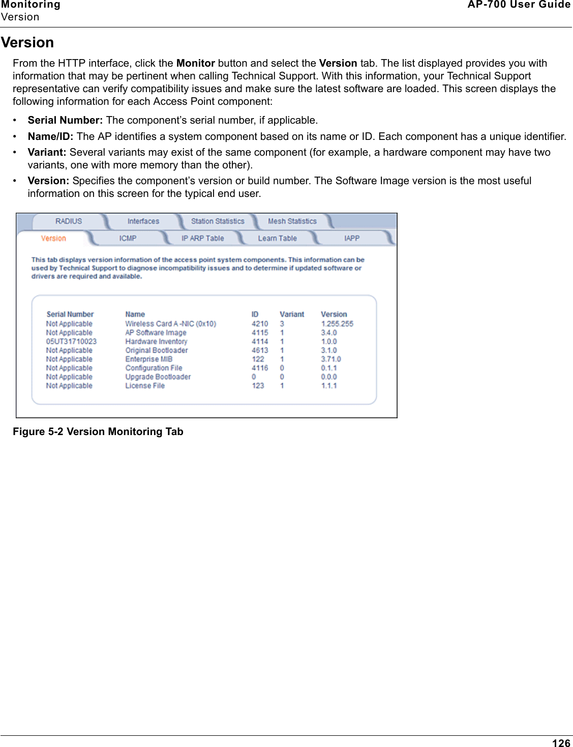
Monitoring AP-700 User GuideVersion126VersionFrom the HTTP interface, click the Monitor button and select the Version tab. The list displayed provides you with information that may be pertinent when calling Technical Support. With this information, your Technical Support representative can verify compatibility issues and make sure the latest software are loaded. This screen displays the following information for each Access Point component:•Serial Number: The component’s serial number, if applicable.•Name/ID: The AP identifies a system component based on its name or ID. Each component has a unique identifier.•Variant: Several variants may exist of the same component (for example, a hardware component may have two variants, one with more memory than the other).•Version: Specifies the component’s version or build number. The Software Image version is the most useful information on this screen for the typical end user.Figure 5-2 Version Monitoring Tab
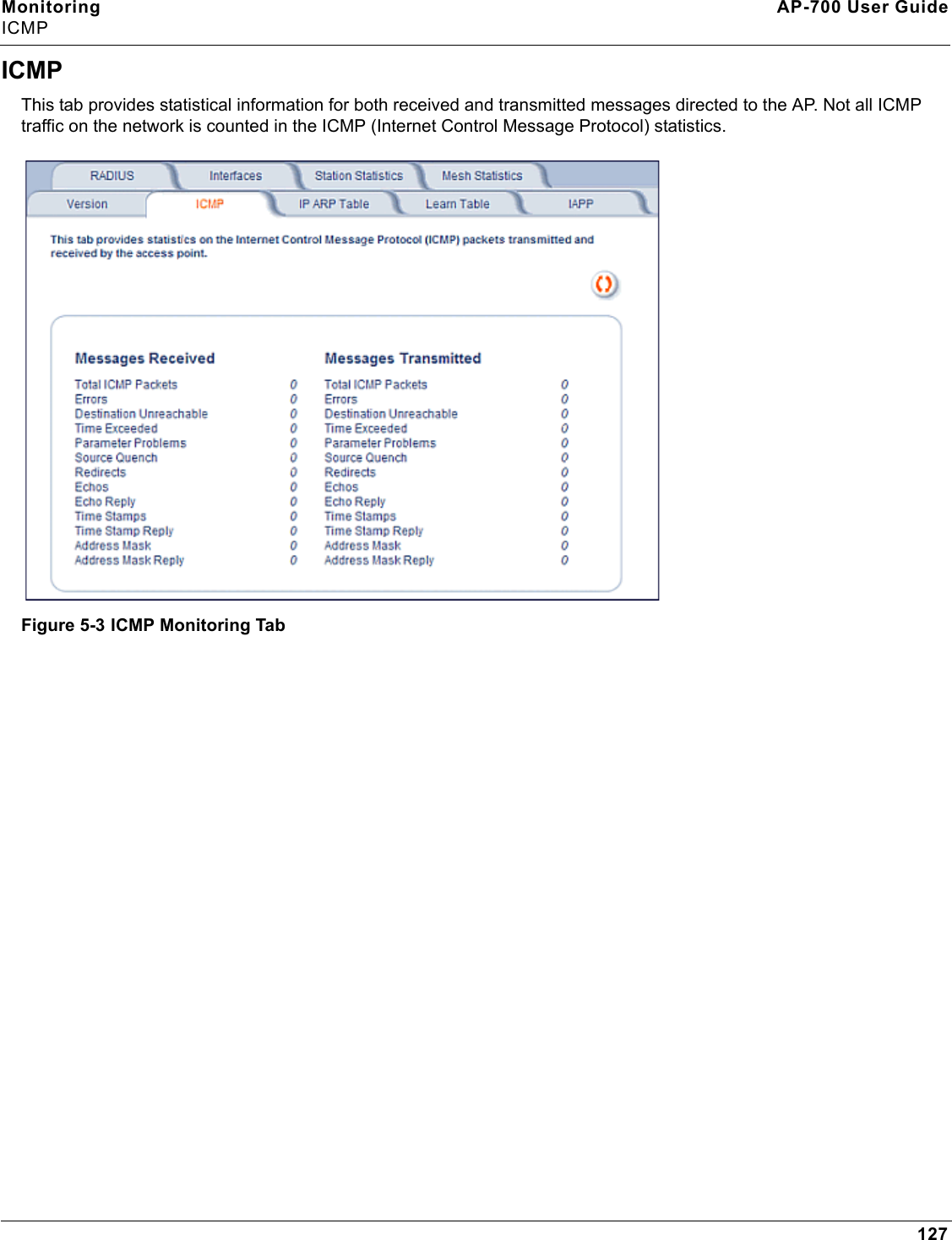
Monitoring AP-700 User GuideICMP127ICMPThis tab provides statistical information for both received and transmitted messages directed to the AP. Not all ICMP traffic on the network is counted in the ICMP (Internet Control Message Protocol) statistics.Figure 5-3 ICMP Monitoring Tab
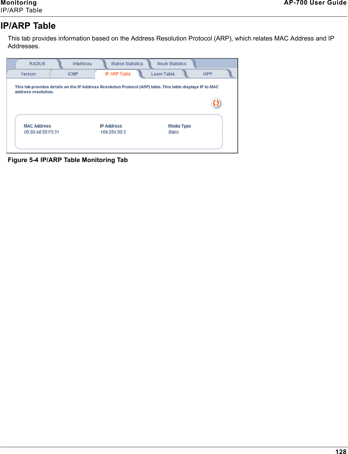
Monitoring AP-700 User GuideIP/ARP Table128IP/ARP TableThis tab provides information based on the Address Resolution Protocol (ARP), which relates MAC Address and IP Addresses. Figure 5-4 IP/ARP Table Monitoring Tab
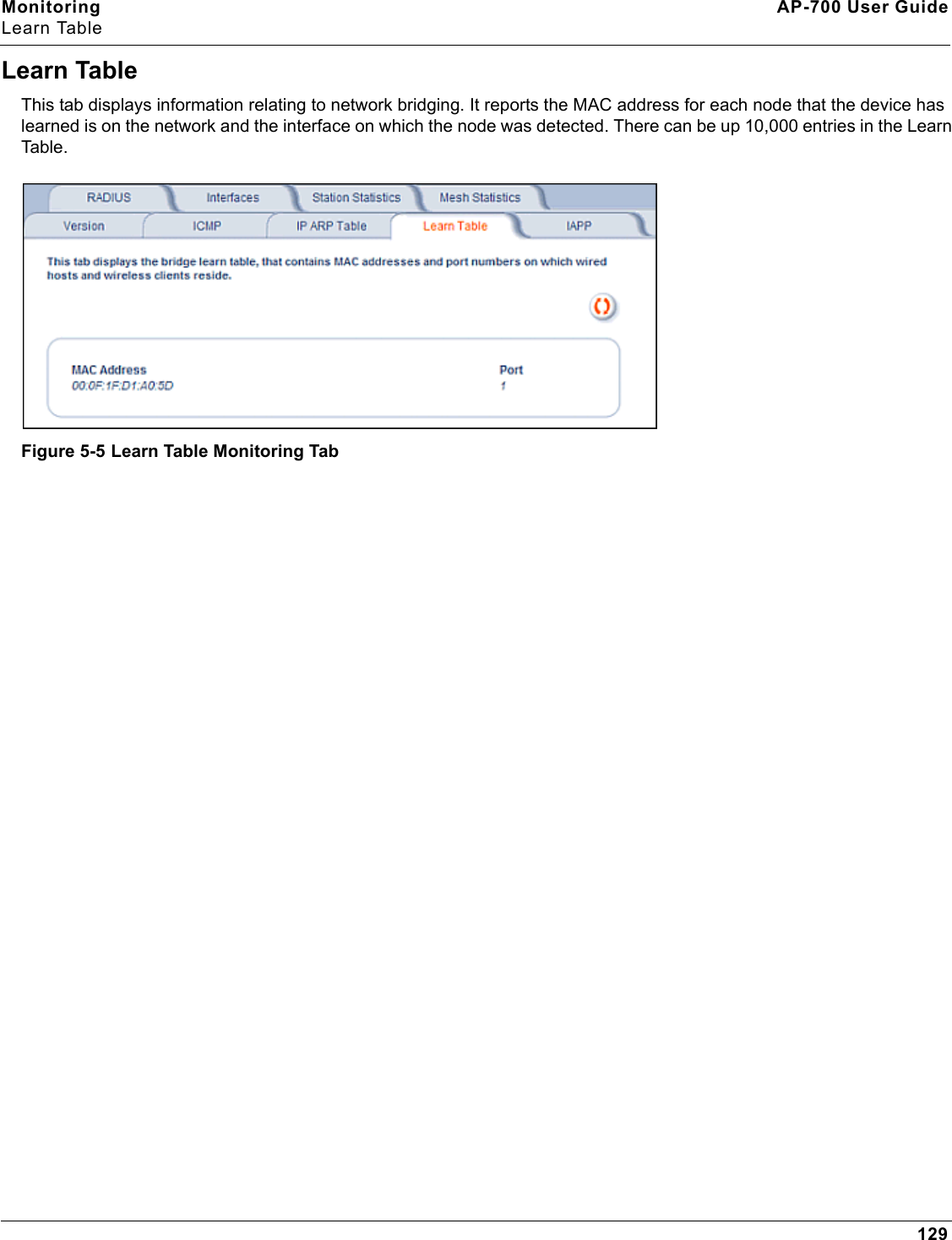
Monitoring AP-700 User GuideLearn Table129Learn TableThis tab displays information relating to network bridging. It reports the MAC address for each node that the device has learned is on the network and the interface on which the node was detected. There can be up 10,000 entries in the Learn Table.Figure 5-5 Learn Table Monitoring Tab
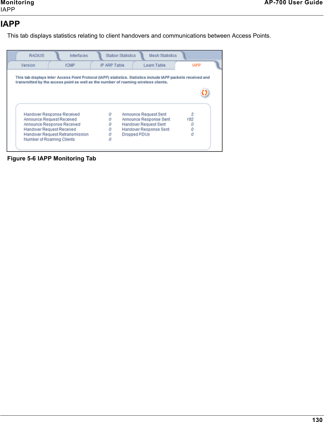
Monitoring AP-700 User GuideIAPP130IAPPThis tab displays statistics relating to client handovers and communications between Access Points. Figure 5-6 IAPP Monitoring Tab
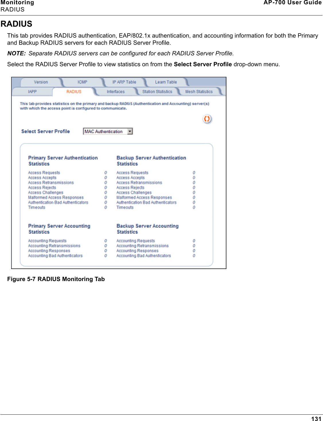
Monitoring AP-700 User GuideRADIUS131RADIUSThis tab provides RADIUS authentication, EAP/802.1x authentication, and accounting information for both the Primary and Backup RADIUS servers for each RADIUS Server Profile. NOTE: Separate RADIUS servers can be configured for each RADIUS Server Profile.Select the RADIUS Server Profile to view statistics on from the Select Server Profile drop-down menu.Figure 5-7 RADIUS Monitoring Tab
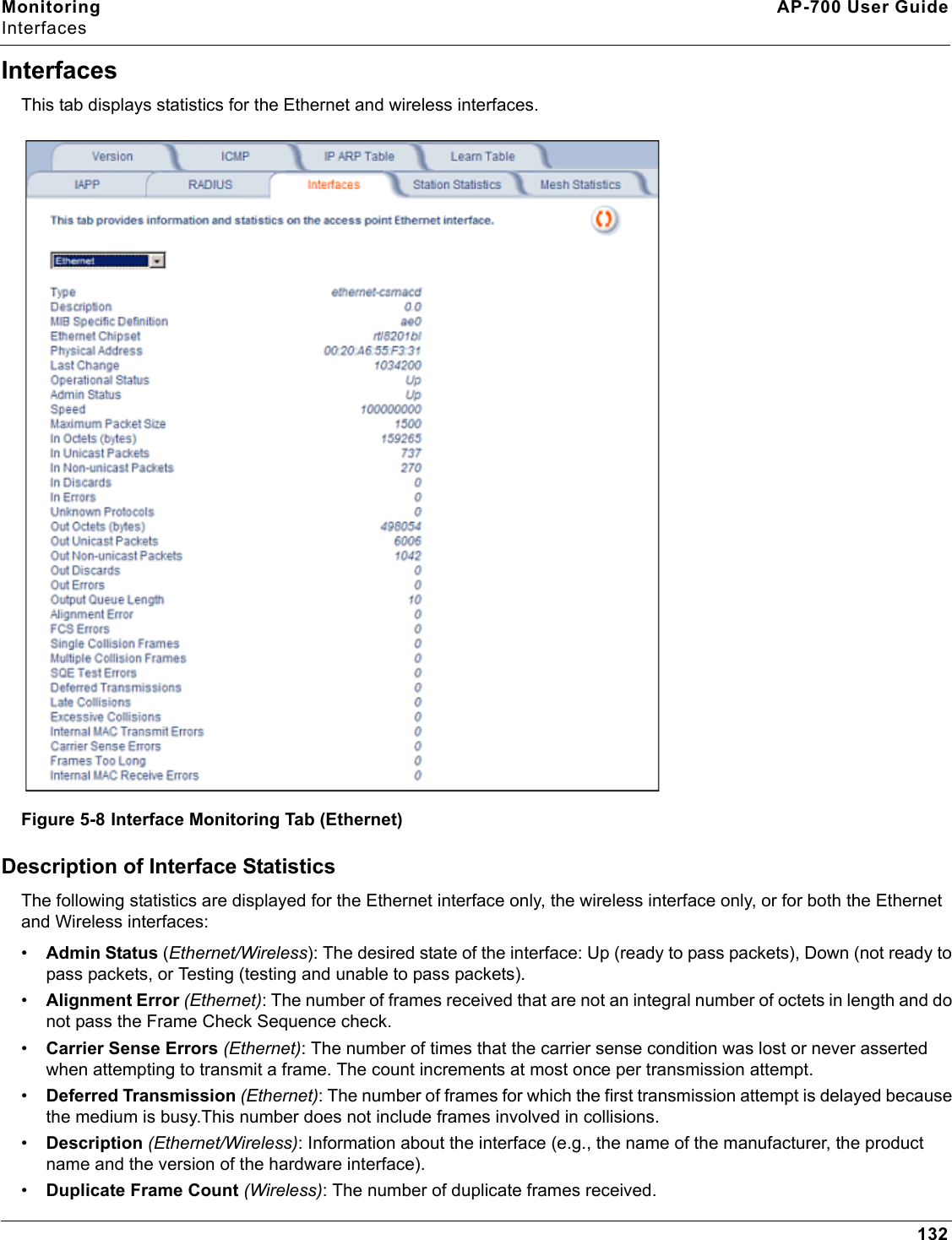
Monitoring AP-700 User GuideInterfaces132InterfacesThis tab displays statistics for the Ethernet and wireless interfaces. Figure 5-8 Interface Monitoring Tab (Ethernet)Description of Interface StatisticsThe following statistics are displayed for the Ethernet interface only, the wireless interface only, or for both the Ethernet and Wireless interfaces:•Admin Status (Ethernet/Wireless): The desired state of the interface: Up (ready to pass packets), Down (not ready to pass packets, or Testing (testing and unable to pass packets).•Alignment Error (Ethernet): The number of frames received that are not an integral number of octets in length and do not pass the Frame Check Sequence check.•Carrier Sense Errors (Ethernet): The number of times that the carrier sense condition was lost or never asserted when attempting to transmit a frame. The count increments at most once per transmission attempt.•Deferred Transmission (Ethernet): The number of frames for which the first transmission attempt is delayed because the medium is busy.This number does not include frames involved in collisions.•Description (Ethernet/Wireless): Information about the interface (e.g., the name of the manufacturer, the product name and the version of the hardware interface).•Duplicate Frame Count (Wireless): The number of duplicate frames received.
Monitoring AP-700 User GuideInterfaces133•Ethernet Chipset (Ethernet): Identifies the chipset used to realize the interface. •Excessive Collisions (Ethernet): The number of frames for which transmission fails due to excessive collisions.•Failed ACK Count (Wireless): The number of times an acknowledgment (or ACK) is not received when expected.•Failed Count (Wireless): The number of packets not transmitted successfully due to too many transmit attempts.•Failed RTS Count (Wireless: The number of times a Clear to Send (CTS) is not received in response to a Request to Send (RTS).•FCS Error (Wireless): The number of Frame Check Sequence errors detected in received MAC Protocol Data Units (MPDUs).•FCS Errors (Ethernet): The number of frames received that are an integral number of octets in length but do not pass the Frame Check Sequence check.•Frames Too Long (Ethernet): The number of frames received that exceed the maximum permitted frame size.•In Discards (Ethernet/Wireless): The number of error-free inbound packets that were chosen to be discarded to prevent their being deliverable to a higher-layer protocol. One possible reason for discarding such a packet could be to free up buffer space.•In Errors (Ethernet/Wireless): The number of inbound packets that contained errors preventing them from being deliverable to a higher-layer protocol.•In Non-unicast Packets (Ethernet/Wireless): The number of non-unicast (i.e., subnetwork-broadcast or subnetwork-multicast) packets delivered to a higher-layer protocol.•In Octets (bytes) (Ethernet/Wireless): The total number of octets received on the interface, including framing characters.•In Unicast Packets (Ethernet/Wireless): The number of subnetwork unicast packets delivered to a higher-layer protocol.•Internal MAC Receive Errors (Ethernet): The number of frames for which reception fails due to an internal MAC sublayer transmit error. A frame is only counted if it is not counted by the Frames Too Long, Alignment Error, or FCS Error counters. •Internal MAC Transmit Errors (Ethernet): The number of frames for which transmission fails due to an internal MAC sublayer transmit error. A frame is only counted if it is not counted by Late Collision, Excession Collision, or Carrier Sense Error counters.•Last Change (Ethernet/Wireless): The value of the sysUpTime object at the time the interface entered its current operational state. •Late Collisions (Ethernet): The number of times that a collision is detected on a particular interface later than 512 bit-times into the transmission of a packet•MAC Address (Wireless): The station's assigned, unique MAC address,•Maximum Packet Size (Ethernet/Wireless): The size (in octets) of the largest datagram which can be sent/received•MIB Specific Definition (Ethernet/Wireless): A reference to MIB definitions specific to the particular media being used to realize the interface. For example, if the interface is an Ethernet interface, then this field refers to a document defining objects specific to ethernet.•Multicast Received Frame Count (Wireless): The number of multicast packets received.•Multicast Transmitted Frame Count (Wireless): The number of multicast packets transmitted.•Multiple Collision Frames (Ethernet): The number of successfully transmitted frames for which transmission is inhibited by more than one collision.•Multiple Retry Count (Wireless): The number of packets successfully transmitted after more than one retransmission.•Operational Status (Ethernet/Wireless): The current state of the interface: Up (ready to pass packets), Down (not ready to pass packets, or Testing (testing and unable to pass packets).•Out Discards (Ethernet/Wireless): The number of error-free outbound packets chosen to be discarded to prevent their being transmitted. One possible reason for discarding such a packet could be to free up buffer space.
Monitoring AP-700 User GuideInterfaces134•Out Errors (Ethernet/Wireless): The number of outbound packets that could not be transmitted because of errors.•Out Non-unicast Packets (Ethernet/Wireless): The total number of packets that higher-level protocols requested be transmitted to a non-unicast (i.e., a subnetwork-broadcast orsubnetwork-multicast) address, including those that were discarded or not sent.•Out Octets (bytes) (Ethernet/Wireless): The total number of octets transmitted out of the interface, including framing characters.•Out Unicast Packets (Ethernet/Wireless): The total number of packets that higher-level protocols requested be transmitted to a subnetwork-unicast address, including those that were discarded or not sent.•Output Queue Length (Ethernet/Wireless): The length of the output packet queue (in packets).•Physical Address (Ethernet): The interface's address at the protocol layer immediately below the network layer in the protocol stack.•Received Fragment Count (Wireless): The number of successfully received Data or Management MAC Protocol Data Units (MPDUs).•Retry Count (Wireless): The number of packets successfully transmitted after one or more retransmissions.•Single Collision Frames (Ethernet): The number of successfully transmitted frames for which transmission is inhibited by exactly one collision•Speed (Ethernet/Wireless): An estimate of the interface's current bandwidth in bits per second. •SQE Test Errors (Ethernet): The number of times that the Signal Quality Error (SQE) Test Error message is generated by the physical layer signalling (PLS) sublayer.•Successful RTS Count (Wireless): The number of times a Clear to Send (CTS) is received in response to an Request to Send (RTS).•Transmitted Fragment Count (Wireless): The number of transmitted fragmented packets.•Transmitted Frame Count (Wireless): This number of successfully transmitted packets.•Type (Ethernet/Wireless): The type of interface, distinguished according to the physical/link protocol(s) immediately below the network layer in the protocol stack.•Unknown Protocols (Ethernet/Wireless): The number of packets received that were discarded because of an unknown or unsupported protocol.•WEP Undecryptable Count (Wireless): The number of undecryptable WEP frames received.
Monitoring AP-700 User GuideStation Statistics135Station StatisticsThis tab displays information on wireless clients attached to the AP and on Wireless Distribution System.Enable the Monitoring Station Statistics feature (Station Statistics are disabled by default) by checking Enable Monitoring Station Statistics and click OK.You do not need to reboot the AP for the changes to take effect. If clients are connected to the device or WDS links are configured for the device, the statistics will now be shown on the screen. Click Select to view the more detailed statistics for a client.Click on the Refresh button in the browser window to view the latest statistics. If any new clients associate to the AP, you can see the statistics of the new clients after you click the refresh button.Figure 5-9 Station Statistics Monitoring TabDescription of Station StatisticsThe following stations statistics are displayed:•MAC Address: The MAC address of the wireless client for which the statistics are gathered. For WDS links, this is the partner MAC address of the link.•IP Address: The IP address of the associated wireless station for which the Statistics are gathered. (0.0.0.0 for WDS links)•Interface to which the Station is connected: The interface number on which the client is connected with the AP. For WDS links this is the interface on which the link is configured.•MAC Protocol: The MAC protocol for this wireless client (or WDS link partner). The possible values are 802.11a, 802.11b, 802.11g.•Signal / Noise: The Signal /Noise Level measured at the AP when frames are received from the associated wireless station (or WDS link partner).
Monitoring AP-700 User GuideStation Statistics136•Time since Last Frame Received: The time elapsed since the last frame from the associated wireless station (or WDS link partner) was received.•Number of Stations and WDS Links: The number of stations and WDS links monitored.The following stations statistics are available through SNMP:•Octets Received: The number of octets received from the associated wireless station (or WDS link partner) by the AP.•Unicast Frames Received: The number of Unicast frames received from the associated wireless station (or WDS link partner) by the AP.•Non-Unicast Frames Received: The number of Non-Unicast frames received (i.e. broadcast or multicast) from the associated wireless station (or WDS link partner) by the AP.•Octets Transmitted: The number of octets sent to the associated wireless station (or WDS link partner) from the AP.•Unicast Frames Transmitted: The number of Unicast frames transmitted to the associated wireless station (or WDS link partner) from the AP.
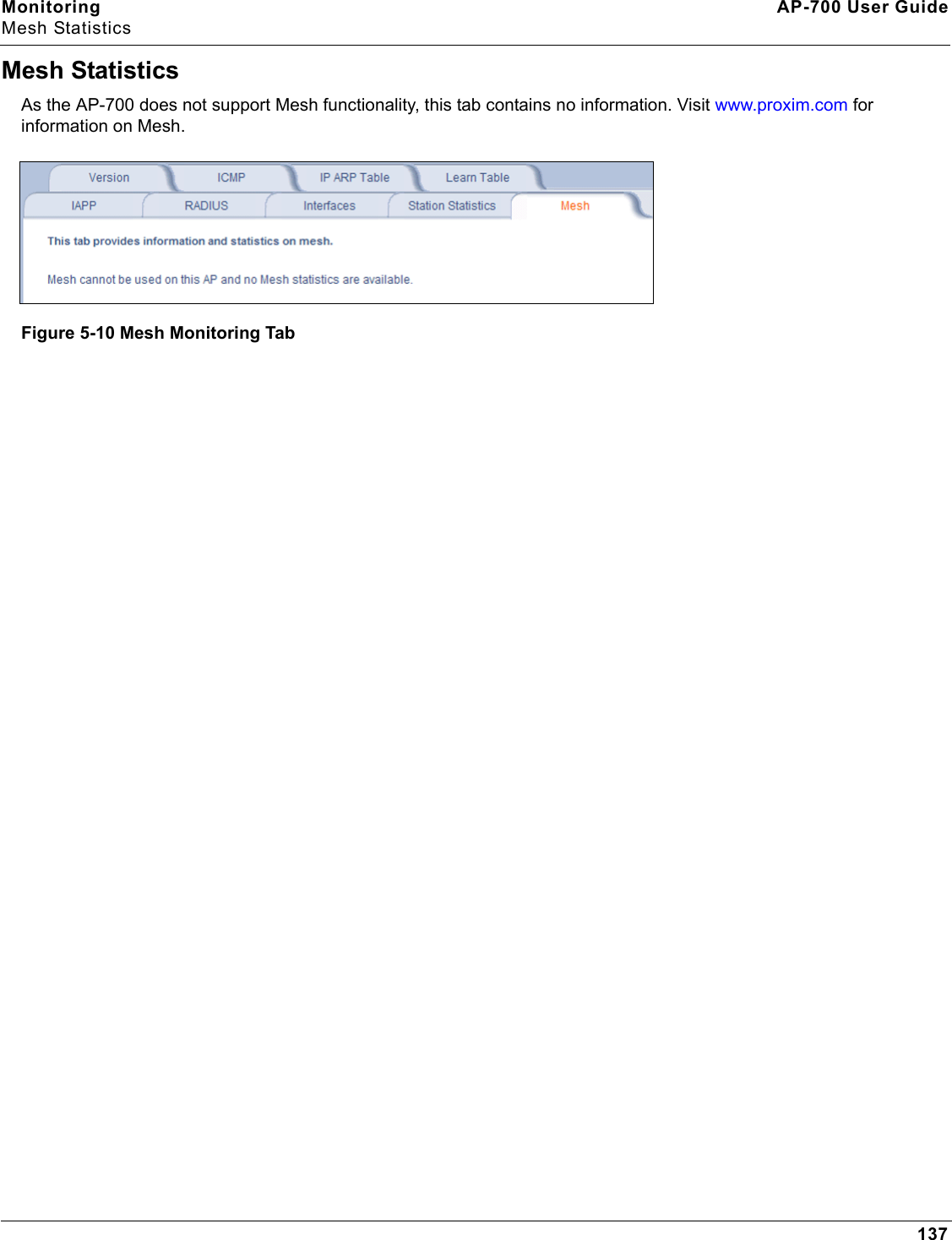
Monitoring AP-700 User GuideMesh Statistics137Mesh StatisticsAs the AP-700 does not support Mesh functionality, this tab contains no information. Visit www.proxim.com for information on Mesh.Figure 5-10 Mesh Monitoring Tab
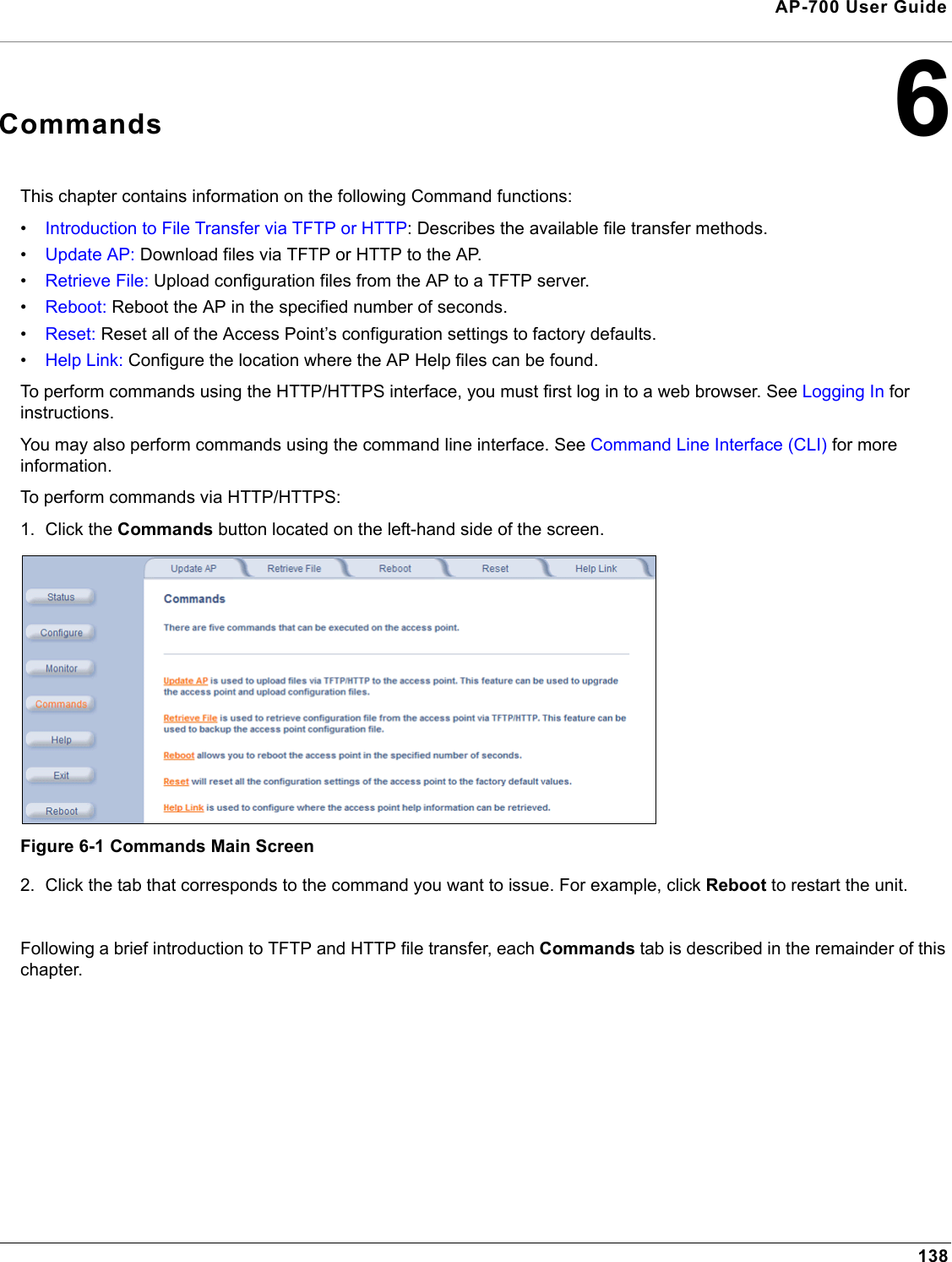
138AP-700 User Guide6CommandsThis chapter contains information on the following Command functions:•Introduction to File Transfer via TFTP or HTTP: Describes the available file transfer methods.•Update AP: Download files via TFTP or HTTP to the AP.•Retrieve File: Upload configuration files from the AP to a TFTP server.•Reboot: Reboot the AP in the specified number of seconds.•Reset: Reset all of the Access Point’s configuration settings to factory defaults.•Help Link: Configure the location where the AP Help files can be found.To perform commands using the HTTP/HTTPS interface, you must first log in to a web browser. See Logging In for instructions. You may also perform commands using the command line interface. See Command Line Interface (CLI) for more information.To perform commands via HTTP/HTTPS:1. Click the Commands button located on the left-hand side of the screen.Figure 6-1 Commands Main Screen2. Click the tab that corresponds to the command you want to issue. For example, click Reboot to restart the unit.Following a brief introduction to TFTP and HTTP file transfer, each Commands tab is described in the remainder of this chapter.
Commands AP-700 User GuideIntroduction to File Transfer via TFTP or HTTP139Introduction to File Transfer via TFTP or HTTPThere are two methods of transferring files to or from the AP: TFTP or HTTP (or HTTPS if enabled):• Downloading files (Configuration, AP Image, Bootloader, License, Private Key, Certificate, CLI Batch File) to the AP using one of these two methods is called “Updating the AP.” • Uploading files (Configuration, CLI Batch File, etc) from the AP is called “Retrieving Files.”TFTP File Transfer GuidelinesA TFTP server must be running and configured to point to the directory containing the file. If you do not have a TFTP server installed on your system, install the TFTP server from the installation CD.HTTP File Transfer GuidelinesHTTP file transfer can be performed either with or without SSL enabled.HTTP file transfers with SSL require enabling Secure Management and Secure Socket Layer. HTTP transfers that use SSL may take additional time.NOTE: SSL requires Internet Explorer version 6, 128 bit encryption, Service Pack 1, and patch Q323308.Image Error Checking During File TransferThe Access Point performs checks to verify that an image downloaded through HTTP or TFTP is valid. The following checks are performed on the downloaded image:• Zero Image size• Large image size• Non VxWorks image• AP image• Digital signature verificationIf any of the above checks fail on the downloaded image, the Access Point deletes the downloaded image and retains the old image. Otherwise, if all checks pass successfully, the AP deletes the old image and retains the downloaded image. These checks are to ensure that the AP does not enter an invalid image state. The storage of the two images is only temporary to ensure the proper verification; the two images will not be stored in the AP permanently.Image error checking functions automatically in the background. No user configuration is required.
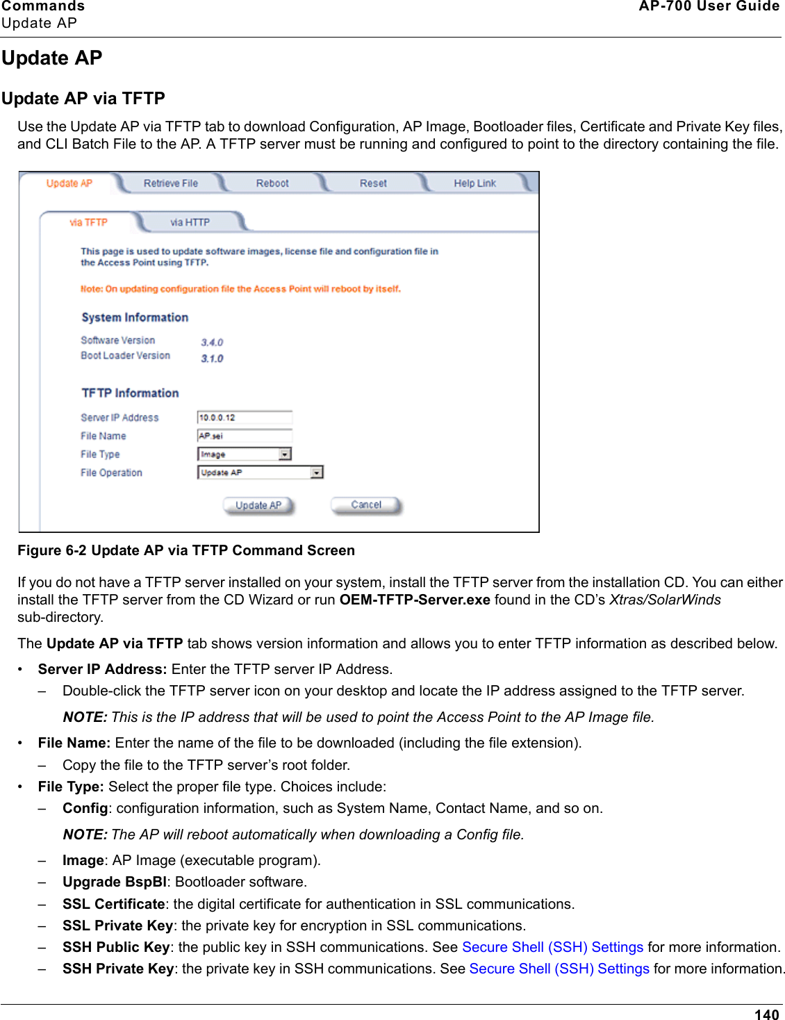
Commands AP-700 User GuideUpdate AP140Update APUpdate AP via TFTPUse the Update AP via TFTP tab to download Configuration, AP Image, Bootloader files, Certificate and Private Key files, and CLI Batch File to the AP. A TFTP server must be running and configured to point to the directory containing the file.Figure 6-2 Update AP via TFTP Command ScreenIf you do not have a TFTP server installed on your system, install the TFTP server from the installation CD. You can either install the TFTP server from the CD Wizard or run OEM-TFTP-Server.exe found in the CD’s Xtras/SolarWinds sub-directory.The Update AP via TFTP tab shows version information and allows you to enter TFTP information as described below.•Server IP Address: Enter the TFTP server IP Address.– Double-click the TFTP server icon on your desktop and locate the IP address assigned to the TFTP server.NOTE: This is the IP address that will be used to point the Access Point to the AP Image file.•File Name: Enter the name of the file to be downloaded (including the file extension). – Copy the file to the TFTP server’s root folder.•File Type: Select the proper file type. Choices include: –Config: configuration information, such as System Name, Contact Name, and so on.NOTE: The AP will reboot automatically when downloading a Config file.–Image: AP Image (executable program).–Upgrade BspBl: Bootloader software.–SSL Certificate: the digital certificate for authentication in SSL communications.–SSL Private Key: the private key for encryption in SSL communications.–SSH Public Key: the public key in SSH communications. See Secure Shell (SSH) Settings for more information.–SSH Private Key: the private key in SSH communications. See Secure Shell (SSH) Settings for more information.
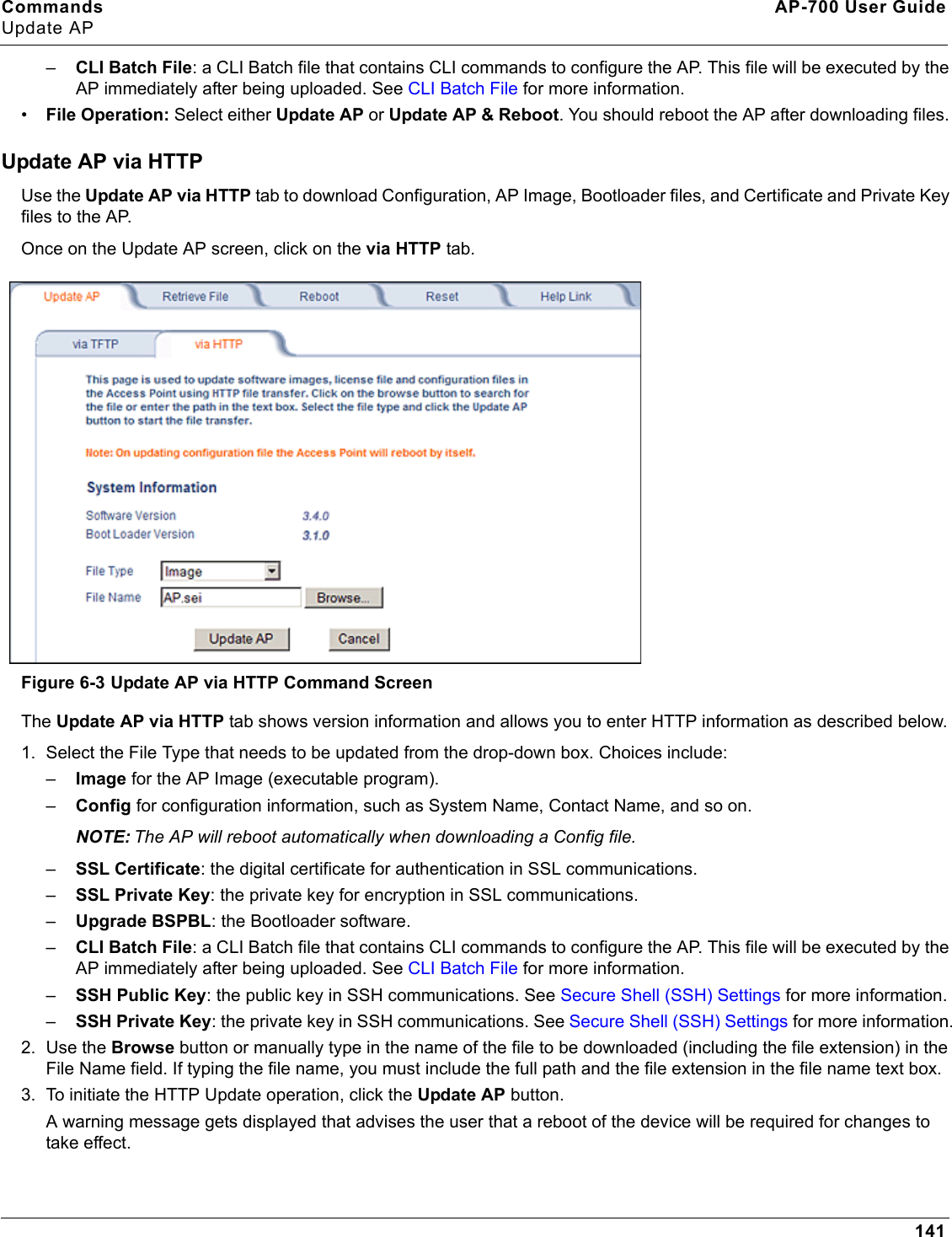
Commands AP-700 User GuideUpdate AP141–CLI Batch File: a CLI Batch file that contains CLI commands to configure the AP. This file will be executed by the AP immediately after being uploaded. See CLI Batch File for more information.•File Operation: Select either Update AP or Update AP & Reboot. You should reboot the AP after downloading files. Update AP via HTTPUse the Update AP via HTTP tab to download Configuration, AP Image, Bootloader files, and Certificate and Private Key files to the AP. Once on the Update AP screen, click on the via HTTP tab.Figure 6-3 Update AP via HTTP Command ScreenThe Update AP via HTTP tab shows version information and allows you to enter HTTP information as described below.1. Select the File Type that needs to be updated from the drop-down box. Choices include: –Image for the AP Image (executable program).–Config for configuration information, such as System Name, Contact Name, and so on.NOTE: The AP will reboot automatically when downloading a Config file.–SSL Certificate: the digital certificate for authentication in SSL communications.–SSL Private Key: the private key for encryption in SSL communications.–Upgrade BSPBL: the Bootloader software.–CLI Batch File: a CLI Batch file that contains CLI commands to configure the AP. This file will be executed by the AP immediately after being uploaded. See CLI Batch File for more information.–SSH Public Key: the public key in SSH communications. See Secure Shell (SSH) Settings for more information.–SSH Private Key: the private key in SSH communications. See Secure Shell (SSH) Settings for more information.2. Use the Browse button or manually type in the name of the file to be downloaded (including the file extension) in the File Name field. If typing the file name, you must include the full path and the file extension in the file name text box.3. To initiate the HTTP Update operation, click the Update AP button. A warning message gets displayed that advises the user that a reboot of the device will be required for changes to take effect.
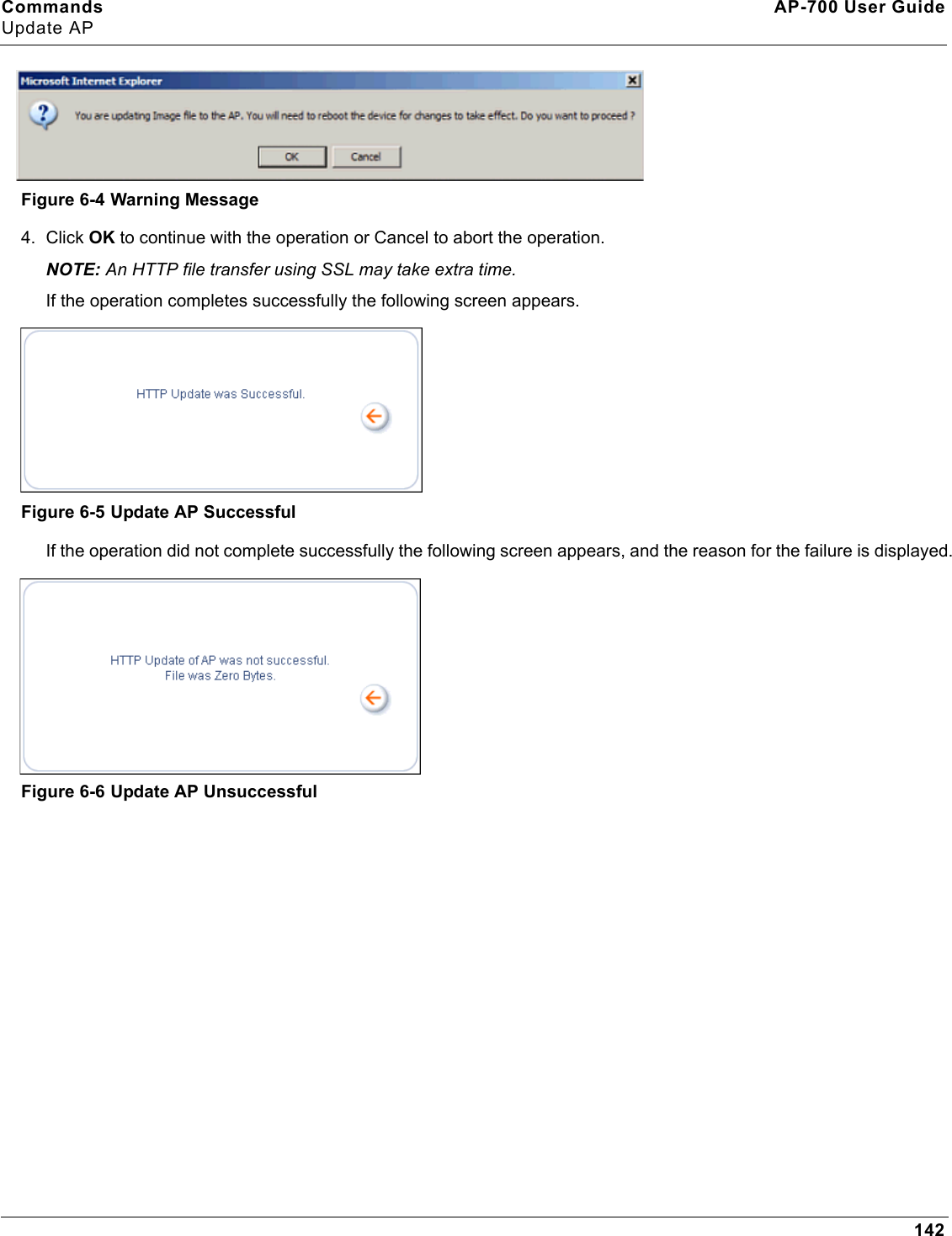
Commands AP-700 User GuideUpdate AP142Figure 6-4 Warning Message4. Click OK to continue with the operation or Cancel to abort the operation.NOTE: An HTTP file transfer using SSL may take extra time.If the operation completes successfully the following screen appears.Figure 6-5 Update AP SuccessfulIf the operation did not complete successfully the following screen appears, and the reason for the failure is displayed.Figure 6-6 Update AP Unsuccessful
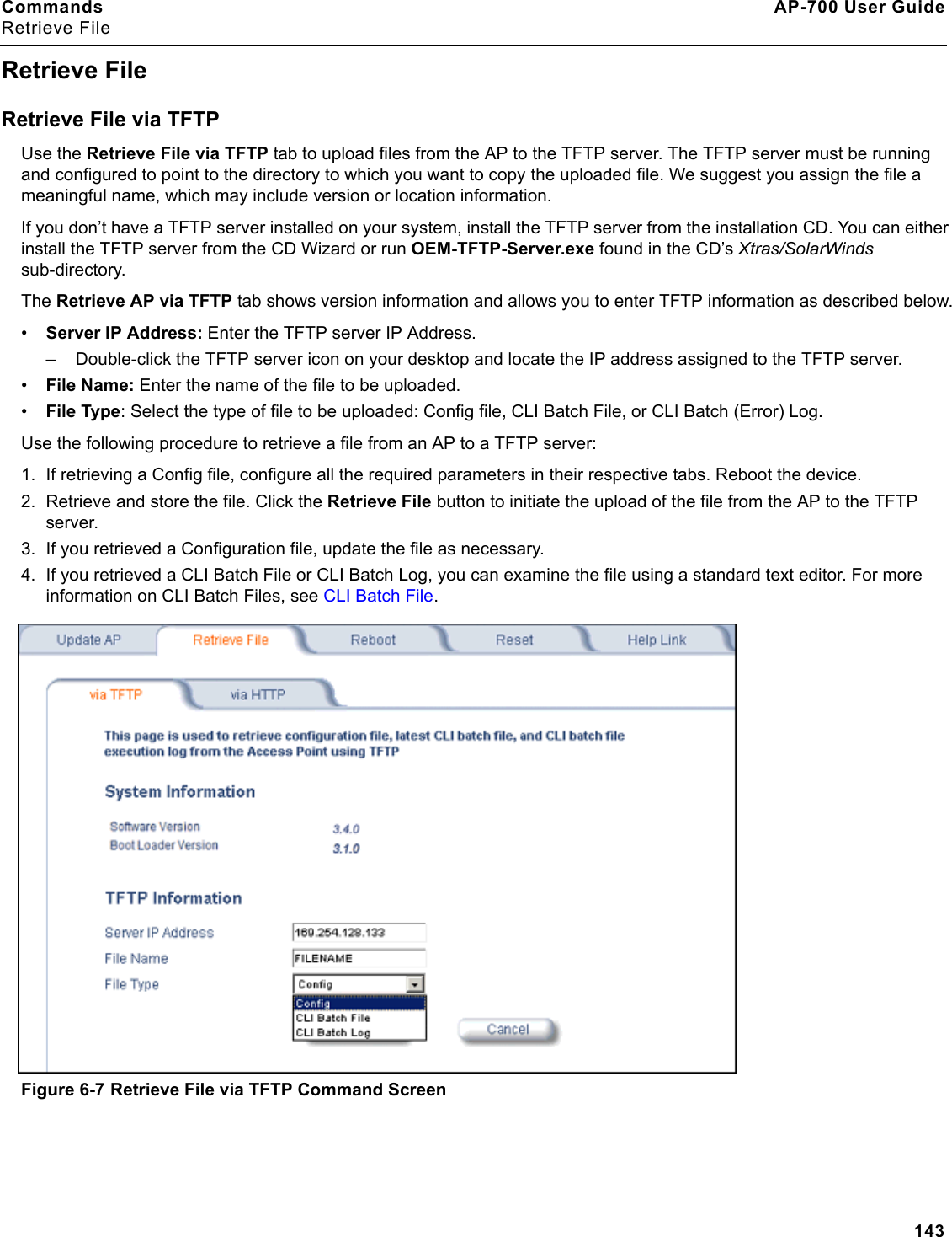
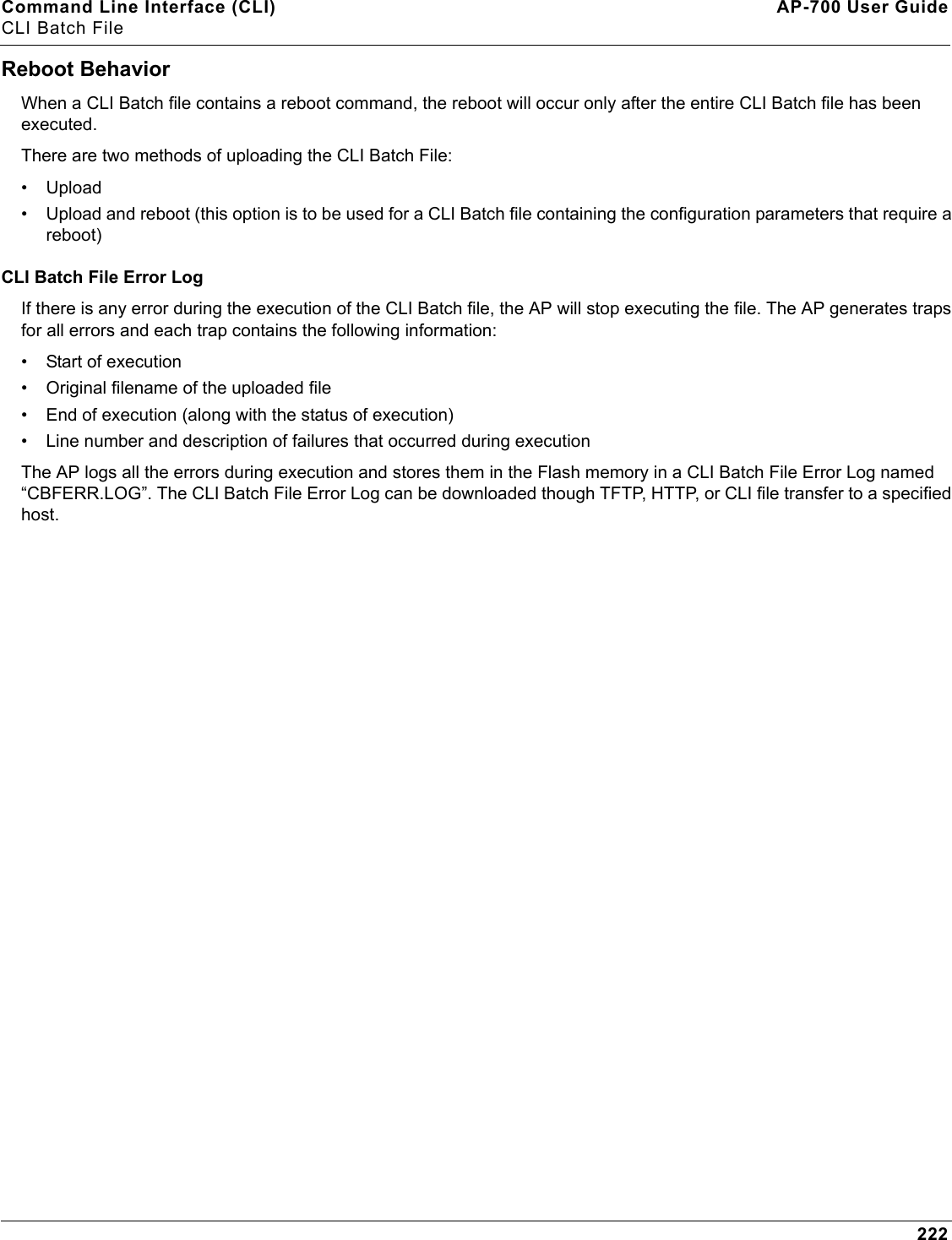
Commands AP-700 User GuideRetrieve File143Retrieve FileRetrieve File via TFTPUse the Retrieve File via TFTP tab to upload files from the AP to the TFTP server. The TFTP server must be running and configured to point to the directory to which you want to copy the uploaded file. We suggest you assign the file a meaningful name, which may include version or location information.If you don’t have a TFTP server installed on your system, install the TFTP server from the installation CD. You can either install the TFTP server from the CD Wizard or run OEM-TFTP-Server.exe found in the CD’s Xtras/SolarWinds sub-directory.The Retrieve AP via TFTP tab shows version information and allows you to enter TFTP information as described below.•Server IP Address: Enter the TFTP server IP Address.– Double-click the TFTP server icon on your desktop and locate the IP address assigned to the TFTP server.•File Name: Enter the name of the file to be uploaded. •File Type: Select the type of file to be uploaded: Config file, CLI Batch File, or CLI Batch (Error) Log.Use the following procedure to retrieve a file from an AP to a TFTP server:1. If retrieving a Config file, configure all the required parameters in their respective tabs. Reboot the device.2. Retrieve and store the file. Click the Retrieve File button to initiate the upload of the file from the AP to the TFTP server. 3. If you retrieved a Configuration file, update the file as necessary.4. If you retrieved a CLI Batch File or CLI Batch Log, you can examine the file using a standard text editor. For more information on CLI Batch Files, see CLI Batch File.Figure 6-7 Retrieve File via TFTP Command Screen
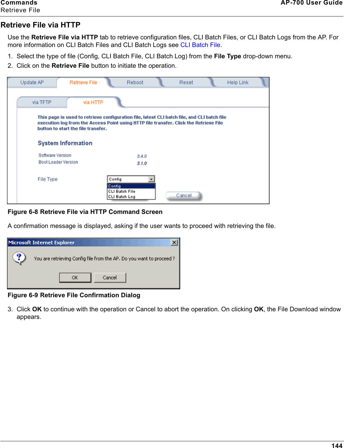
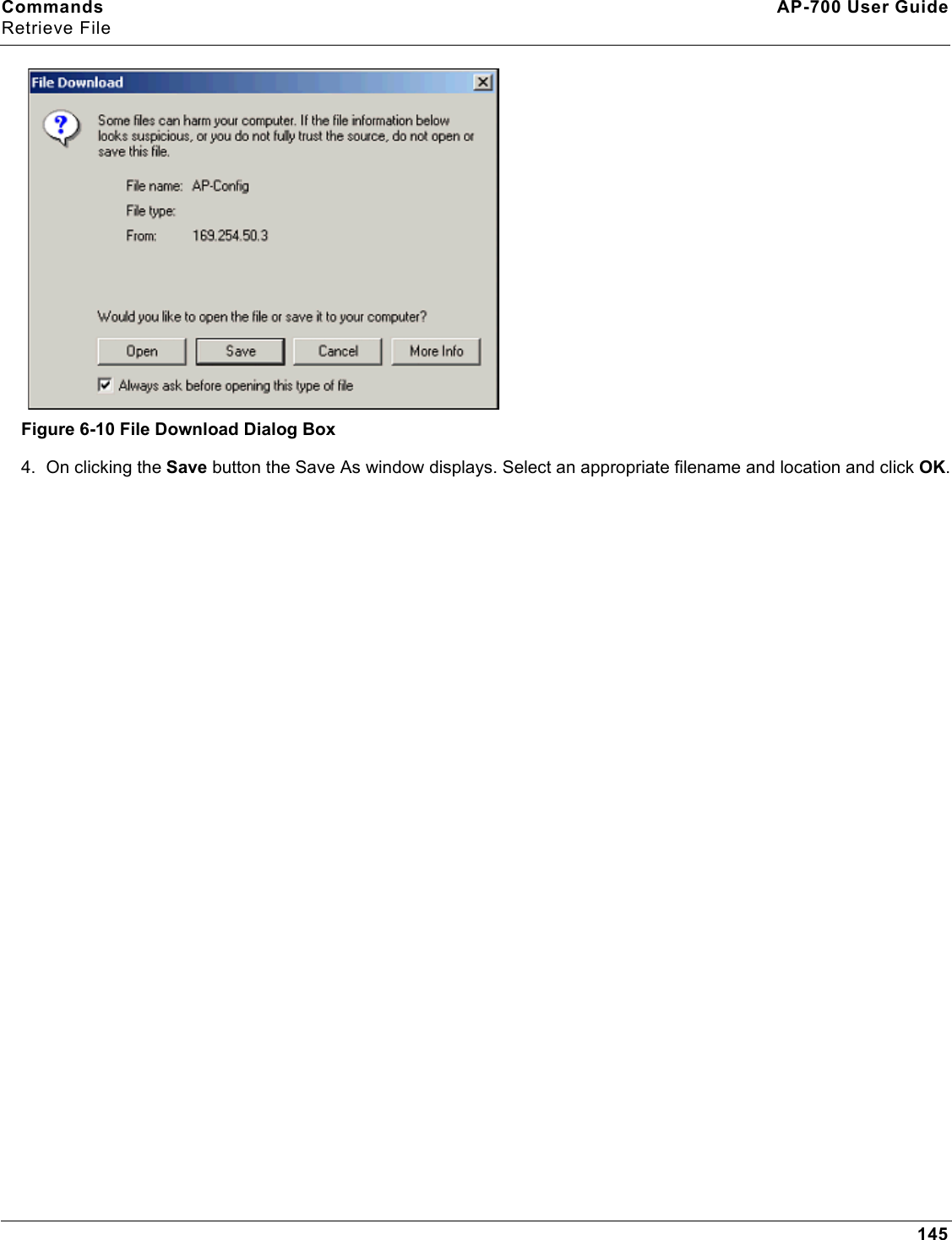
Commands AP-700 User GuideRetrieve File144Retrieve File via HTTPUse the Retrieve File via HTTP tab to retrieve configuration files, CLI Batch Files, or CLI Batch Logs from the AP. For more information on CLI Batch Files and CLI Batch Logs see CLI Batch File.1. Select the type of file (Config, CLI Batch File, CLI Batch Log) from the File Type drop-down menu.2. Click on the Retrieve File button to initiate the operation. Figure 6-8 Retrieve File via HTTP Command ScreenA confirmation message is displayed, asking if the user wants to proceed with retrieving the file. Figure 6-9 Retrieve File Confirmation Dialog3. Click OK to continue with the operation or Cancel to abort the operation. On clicking OK, the File Download window appears.
Commands AP-700 User GuideRetrieve File145Figure 6-10 File Download Dialog Box4. On clicking the Save button the Save As window displays. Select an appropriate filename and location and click OK.
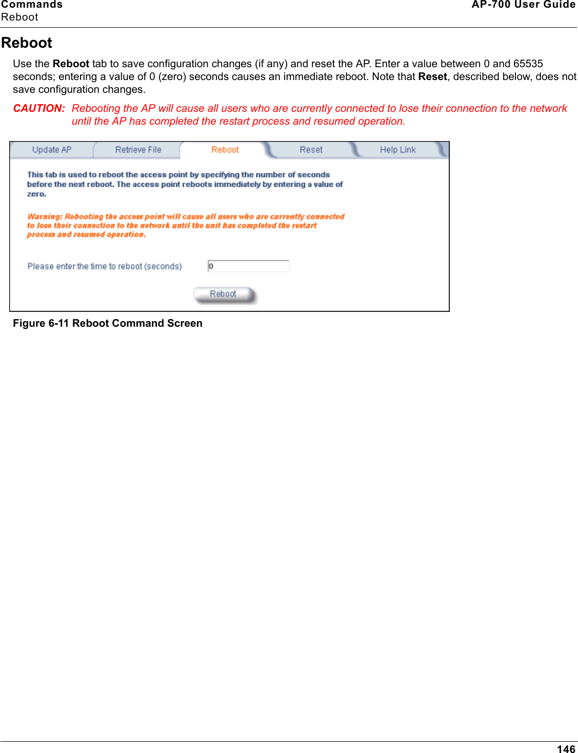
Commands AP-700 User GuideReboot146RebootUse the Reboot tab to save configuration changes (if any) and reset the AP. Enter a value between 0 and 65535 seconds; entering a value of 0 (zero) seconds causes an immediate reboot. Note that Reset, described below, does not save configuration changes.CAUTION: Rebooting the AP will cause all users who are currently connected to lose their connection to the network until the AP has completed the restart process and resumed operation.Figure 6-11 Reboot Command Screen
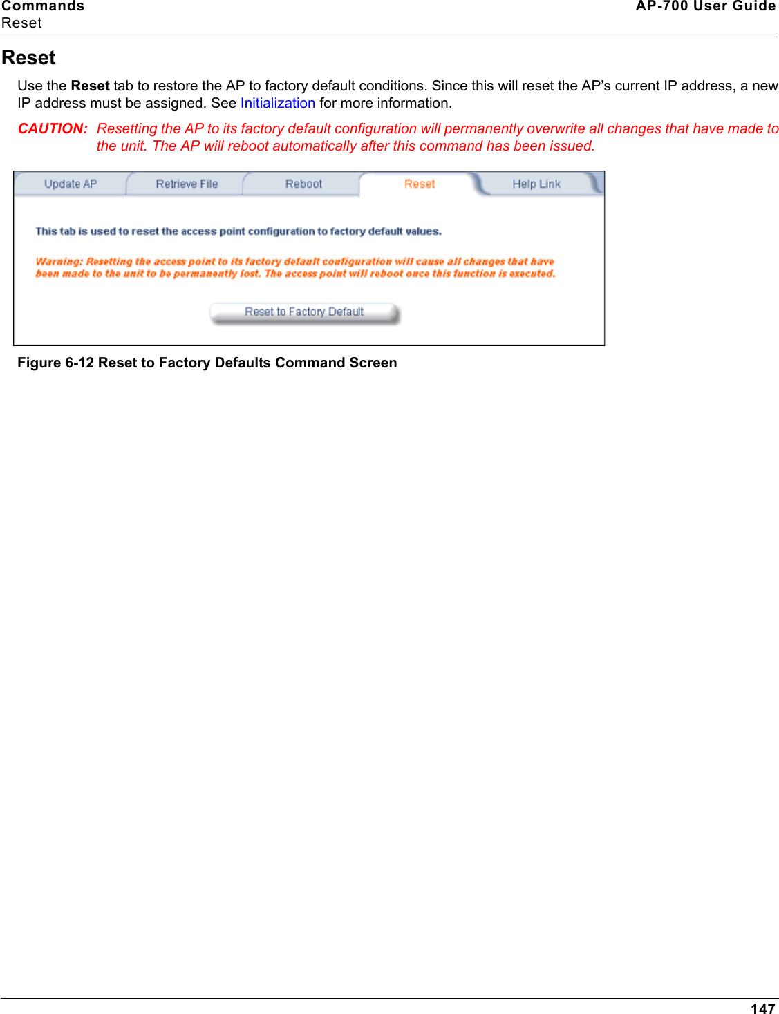
Commands AP-700 User GuideReset147ResetUse the Reset tab to restore the AP to factory default conditions. Since this will reset the AP’s current IP address, a new IP address must be assigned. See Initialization for more information.CAUTION: Resetting the AP to its factory default configuration will permanently overwrite all changes that have made to the unit. The AP will reboot automatically after this command has been issued.Figure 6-12 Reset to Factory Defaults Command Screen
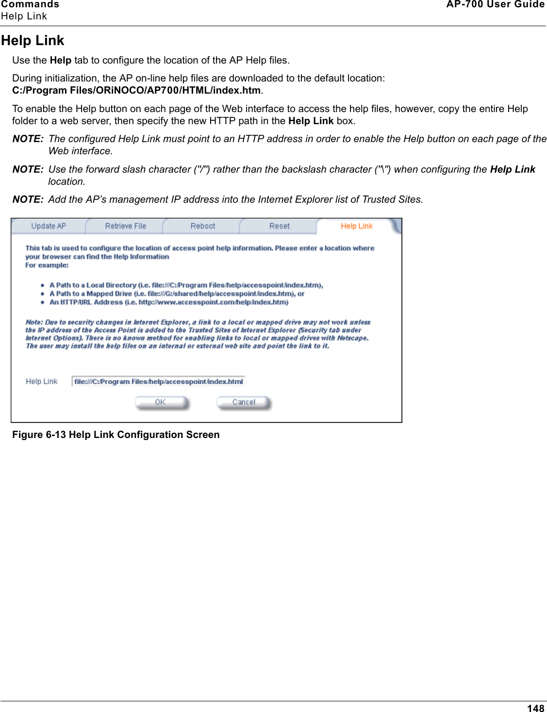
Commands AP-700 User GuideHelp Link148Help LinkUse the Help tab to configure the location of the AP Help files.During initialization, the AP on-line help files are downloaded to the default location: C:/Program Files/ORiNOCO/AP700/HTML/index.htm. To enable the Help button on each page of the Web interface to access the help files, however, copy the entire Help folder to a web server, then specify the new HTTP path in the Help Link box. NOTE: The configured Help Link must point to an HTTP address in order to enable the Help button on each page of the Web interface. NOTE: Use the forward slash character ("/") rather than the backslash character ("\") when configuring the Help Link location.NOTE: Add the AP’s management IP address into the Internet Explorer list of Trusted Sites.Figure 6-13 Help Link Configuration Screen
149AP-700 User Guide7TroubleshootingThis chapter provides information on the following:•Troubleshooting Concepts•Symptoms and Solutions•Recovery Procedures•Related ApplicationsNOTE: This section helps you locate problems related to the AP device setup. For details about RADIUS, TFTP, serial communication programs (such as HyperTerminal), Telnet applications, or web browsers, please see the documentation that came with the respective application for assistance. Troubleshooting ConceptsThe following list identifies important troubleshooting concepts and topics. The most common initialization and installation problems relate to IP addressing. For example, you must have valid IP addresses for both the AP and the management computer to access the unit’s HTTP interface.•IP Address management is fundamental. •Factory default units are set for “Dynamic” (DHCP) IP Address assignment. The default IP address for the AP is 169.254.128.132 if your network does not have a DHCP server. If you connect the AP to a network with an active DHCP server, then use ScanTool to locate the IP address of your unit. If a DHCP server is not active on your subnet, then use ScanTool to assign a static IP address to the unit.•The Trivial File Transfer Protocol (TFTP) provides a means to download and upload files. These files include the AP Image (executable program) and configuration files. •If the AP password is lost or forgotten, you will need to reset to default values. The Soft Reset to Factory Defaults or Hard Reset to Factory Defaults procedures reset the configuration, but do not change the current AP Image. •The AP Supports a Command Line Interface (CLI). If you are having trouble locating your AP on the network, connect to the unit directly using the serial interface and see Command Line Interface (CLI) for CLI command syntax and parameter names.•ScanTool does not work over routers. You must be connected to the same subnet/physical LAN segment to use ScanTool. Note that ScanTool also works over the wireless interface; you can run it on a wireless client connected to the target AP or an AP connected to the same LAN segment/subnet.•If all else fails… Use the Forced Reload procedure to erase the current AP Image and configuration file and then download a new image.
Troubleshooting AP-700 User GuideSymptoms and Solutions150Symptoms and SolutionsConnectivity IssuesConnectivity issues include any problem that prevents you from powering up or connecting to the AP.AP Unit Will Not Boot - No LED Activity1. Make sure your power source is operating.2. Make sure all cables are connected to the AP correctly.3. If you are using PoE, make sure you are using a Category 5, foiled, twisted pair cable to power the AP.Serial Link Does Not Work1. Make sure you are using a standard, straight-through, 9-pin serial cable. 2. Double-check the physical network connections.3. Make sure your PC terminal program (such as HyperTerminal) is active and configured to the following values: – Com Port: (COM1, COM2, etc. depending on your computer); – Baud rate: 9600; Data bits: 8; Stop bits: 1; Flow Control: None; Parity: None;– Line Feeds with Carriage Returns (In HyperTerminal select: File > Properties > Settings > ASCII Setup > Send Line Ends with Line Feeds)Ethernet Link Does Not Work1. Double-check the physical network connections. Use a known-good unit to make sure the network connection is present. Once you have the AP IP address, you can use the “Ping” command over Ethernet to test the IP Address. If the AP responds to the Ping, then the Ethernet Interface is working properly.2. By default, the Access Point will attempt to automatically detect the Ethernet settings. However, if you are having problems with the Ethernet link, manually configure the Access Point’s Ethernet settings. For example, if your switch operates at 100 Mbits/sec/Full Duplex, manually configure the Access Point to use these settings (see Ethernet). If you cannot access the unit over Ethernet, then use the CLI interface over the serial port to configure the Ethernet port (see Command Line Interface (CLI) and Set Ethernet Speed and Transmission Mode).3. Perform network infrastructure troubleshooting (check switches, routers, etc.).Basic Software Setup and Configuration ProblemsLost AP, Telnet, or SNMP Password1. Perform the Soft Reset to Factory Defaults in this guide. This procedure resets system and network parameters, but does not affect the AP Image. The default AP HTTP, Telnet, and SNMP passwords are all public.Client Computer Cannot Connect1. Client computers should have the same Network Name and security settings as the AP.2. Network Names should be allocated and maintained by the Network Administrator.3. See the documentation that came with your client card for additional troubleshooting suggestions. AP Has Incorrect IP Address1. Default IP Address Assignment mode is dynamic (DHCP). If you do not have a DHCP server on your network, the default IP Address is 169.254.128.132. If you have more than one unintialized AP connected to the network, they will all have the same default IP address and you will not be able to communicate with them (due to an IP address conflict). In this case, assign each AP a static IP address via the serial cable or turn off all units but one and change the IP address using ScanTool one at a time.
Troubleshooting AP-700 User GuideSymptoms and Solutions1512. The AP only contacts a DHCP server during boot-up. If your network’s DHCP server is not available while the AP is booting, the device will use the default IP address (169.254.128.132). Reboot the AP once your DHCP server is on-line again or use the ScanTool to find the Access Point’s current IP address.3. To find the unit’s current IP address if using DHCP, open the IP Client Table in the DHCP Server and match the Access Point’s IP address to its MAC address (found on the product label). Alternatively, use ScanTool to identify an Access Point’s current IP address.4. Once you have the current IP address, use the HTTP or CLI Interface to change the unit’s IP settings, if necessary.5. If you use static IP Address assignments, and cannot access the unit over Ethernet, use the Initializing the IP Address using CLI procedure. Once the IP Address is set, you can use the Ethernet Interface to complete configuration.6. Perform the Soft Reset to Factory Defaults in this guide. This will reset the unit to “DHCP” mode. If there is a DHCP Server on the network, the DHCP Server will assign an IP Address to the AP.HTTP Interface or Telnet Interface Does Not Work1. Make sure you are using a compatible browser: – Microsoft Internet Explorer 6 with Service Pack 1 or later– Netscape 7.1 or later2. Make sure you have the proper IP address. Enter your Access Point’s IP Address in the browser address bar, similar to this example:                http://192.168.1.100 When the Enter Network Password window appears, leave the User Name field empty and enter the HTTP password in the Password field. The default HTTP password is public.3. Use the CLI over the serial port to check the IP Access Table, which can be restricting access to Telnet and HTTP.HTML Help Files Do Not Appear1. Verify that the HTML Help files are installed in the default directory:C:/Program Files/ORiNOCO/AP700/HTML.If the Help files are not located in this folder, contact your network administrator to find out where the Help files are located on your server. 2. Copy the entire folder to your Web server. 3. Perform the following steps to specify the path for the Help files:a. Click the Commands button in the HTTP interface.b. Select the Help tab located at the top of the screen.c. Enter the pathname where the Help files are located in the Help Link box. This must be an HTTP address.d. Click OK.Telnet CLI Does Not Work1. Make sure you have the proper IP Address. Enter your AP IP address in the Telnet connection dialog, from a DOS prompt, type:         C:\> telnet <AP IP Address>2. Use the CLI over the serial port to check the IP Access Table, which can be restricting access to Telnet and HTTP.TFTP Server Does Not Work1. Make sure the TFTP Server has been started.2. Verify the IP address of the TFTP Server. The server may be local or remote, so long as it has a valid IP address.3. Configure the TFTP Server to “point” to the folder containing the file to be downloaded (or to the folder in which the file is to be uploaded).4. Verify that you have entered the proper AP Image file name (including the file extension) and directory path (if needed).
Troubleshooting AP-700 User GuideSymptoms and Solutions1525. If you have a problem uploading a file, verify that the TFTP server is configured to allow uploads (typically the default setting is to allow only downloads).Client Connection ProblemsClient Software Finds No ConnectionMake sure you have configured your client software with the proper Network Name and Security settings. Network Names and WEP Keys are typically allocated and maintained by your network administrator.Client PC Card Does Not Work1. Make sure you are using the latest PC Card driver software. 2. Download and install the latest ORiNOCO client software from http://support.proxim.com.Intermittent Loss of Connection1. Make sure you are within range of an active AP. 2. You can check the signal strength using the signal strength gauge on your client software. Client Does Not Receive an IP Address - Cannot Connect to Internet1. If the AP is configured as a DHCP server, open the Web-browser Interface and select the Configure button and then the Network tab to make sure the proper DHCP settings are being used.2. If you are not using the DHCP server feature on the AP, then make sure that your local DHCP server is accessible from the Access Point’s subnet.3. If using PoE, make sure you are not using a crossover Ethernet cable between the AP and the hub.VLAN Operation IssuesVerifying Proper Operation of the VLAN FeatureThe correct VLAN configuration can be verified by “pinging” both wired and wireless hosts from both sides of the AP device and the network switch. Traffic can be “sniffed” on both the wired (Ethernet) and wireless (WDS) backbones (if configured). Bridge frames generated by wireless clients and viewed on one of the backbones should contain IEEE 802.1Q compliant VLAN headers or tags. The VLAN ID in the headers should correspond to one of the VLAN User IDs configured for the AP. NOTE: The AP-700 supports 16 VLAN/SSID pairs, each with a configured security profile.VLAN WorkgroupsThe correct VLAN assignment can be verified by pinging the AP to ensure connectivity, by pinging the switch to ensure VLAN properties, and by pinging hosts past the switch to confirm the switch is functional. Ultimately, traffic can be “sniffed” on the Ethernet or WDS interfaces (if configured) using third-party packages. Most problems can be avoided by ensuring that 802.1Q compliant VLAN tags containing the proper VLAN ID have been inserted in the bridged frames. The VLAN ID in the header should correspond to the user’s assigned network name.What if network traffic is being directed to a nonexistent host?• All sessions are disconnected, traffic is lost, and a Forced Reload is necessary. • Workaround: you can configure the switch to mimic the nonexistent host.I have just configured the Management ID and now I can't manage the AP?• Check to ensure your password is correct. If your password is incorrect or all inbound packets do NOT have the correct tag, then a Forced Reload is necessary.
Troubleshooting AP-700 User GuideSymptoms and Solutions153CAUTION: The Forced Reload procedure disconnects all users and resets all values to factory defaults.Power-Over-Ethernet (PoE)The AP Does Not Work1. Verify that you are using a standard UTP Category 5 cable.2. Try a different port on the same PoE hub (remember to move the input port accordingly) – if it works, there is probably a faulty port or bad RJ-45 port connection.3. If possible, try to connect the AP to a different PoE hub.4. Try using a different Ethernet cable – if it works, there is probably a faulty connection over the long cable, or a bad RJ-45 connection.5. Check power plug and hub.6. If the Ethernet link goes down, check the cable, cable type, switch, and hub.There Is No Data Link 1. Verify that the indicator for the port is “on.”2. Verify that the PoE hub is connected to the Ethernet network with a good connection.3. Verify that the Ethernet cable is Category 5 or better and is less than 100 meters (approximately 325 feet) in length from the Ethernet source to the AP.4. Try to connect a different device to the same port on the PoE hub – if it works and a link is established, there is probably a faulty data link in the AP.5. Try to re-connect the AP to a different output port (remember to move the input port accordingly) – if it works, there is probably a faulty output or input port in the PoE hub or a bad RJ-45 connection.“Overload” Indications1. Verify that you are not using a cross-over cable between the PoE output port and the AP.2. Verify that there is no short over any of the twisted pair cables.3. Move the device into a different output port (remember to move the input port accordingly); if it works, there is probably a faulty port or bad RJ-45 connection.
Troubleshooting AP-700 User GuideRecovery Procedures154Recovery ProceduresThe most common installation problems relate to IP addressing. For example, without the TFTP server IP Address, you will not be able to download a new AP Image to the AP. IP Address management is fundamental. We suggest you create a chart to document and validate the IP addresses for your system.If the password is lost or forgotten, you will need to reset the AP to default values. The Soft Reset to Factory Defaults and Hard Reset to Factory Defaults procedures reset configuration settings, but do not change the current AP Image. If the AP has a corrupted software image, follow the Forced Reload procedure to erase the current AP Image and download a new image.Soft Reset to Factory DefaultsUse this procedure to reset the network configuration values, including the password, IP address, and subnet mask. The current AP Image is not deleted. 1. Click Commands > Reset.2.  Click Reset to Factory Default; the device is reset to its factory default state.3. If not using DHCP, use the ScanTool or use CLI over a serial connection to set the IP address, subnet mask, and other IP parameters. See Command Line Interface (CLI) for CLI information. If you do not have access to the HTTP or CLI interfaces, use the procedure described in Hard Reset to Factory Defaults.Hard Reset to Factory DefaultsIf you cannot access the unit or you have lost its password, you can reset the unit to the factory default settings using the Reload button on the unit, as described below. 1. Using the end of a paper clip or pin, depress and hold the Reload button on the back of the unit for a minimum of 5 seconds but no more than 10 seconds. The configuration is deleted from the unit and the unit reboots, using a factory default configuration.NOTE: You need to use a pin or the end of a paperclip to press the button.CAUTION: If you hold the Reload button for longer than 20 seconds, you may go into Forced Reload mode, which erases the unit’s embedded software. This software must be reloaded through an Ethernet connection with access to a TFTP server. See Forced Reload below for instructions.2. If not using DHCP, use the ScanTool or use CLI over a serial connection to set the IP address, subnet mask, and other IP parameters. See Command Line Interface (CLI) for CLI information. Forced ReloadWith Forced Reload, you bring the unit into bootloader mode by erasing the embedded software. Use this procedure only as a last resort if the unit does not boot and the procedure did not help.CAUTION: By completing this procedure, the embedded software in the AP will be erased. You will need to reload the software before the unit is operational.To do a forced reload:1. While the unit is running, use a pin or the end of a paperclip to press the RESET button.The AP reboots and the indicators begin to flash.2. Press and hold the RELOAD button for about 20 seconds until the POWER LED turns amber. The AP deletes the current AP Image.3. Follow one of the procedures below to load a new AP Image to the Access Point:–Download a New Image Using ScanTool
Troubleshooting AP-700 User GuideRecovery Procedures155–Download a New Image Using the Bootloader CLIBecause the CLI option requires a physical connection to the unit’s serial port, Proxim recommends the ScanTool option.Download a New Image Using ScanToolTo download the AP Image, you will need an Ethernet connection to the computer on which the TFTP server resides and to a computer that is running ScanTool (this is either two separate computers connected to the same network or a single computer running both programs).ScanTool detects if an Access Point does not have a valid software image installed. In this case, the TFTP Server and Image File Name parameters are enabled in the ScanTool’s Change screen so you can download a new image to the unit. (These fields are grayed out if ScanTool does not detect a software image problem.) Preparing to Download the AP ImageBefore starting, you need to know the Access Point’s IP address, subnet mask, the TFTP Server IP Address, and the AP Image file name. Make sure the TFTP server is running and configured to point to the folder containing the image to be downloaded.Download ProcedureFollow these steps to use ScanTool to download a software image to an Access Point with a missing image:1. Download the latest software from http://support.proxim.com. See Download the Software for more detailed instructions.1. Copy the latest software updates to your TFTP server.2. Launch ScanTool.3. Highlight the entry for the AP you want to update and click Change.4. Set IP Address Type to Static. NOTE: You need to assign static IP information temporarily to the Access Point since its DHCP client functionality is not available when no image is installed on the device.5. Enter an unused IP address that is valid on your network in the IP Address field. You may need to contact your network administrator to get this address.6. Enter the network’s Subnet Mask in the field provided.7. Enter the network’s Gateway IP Address, if necessary. You may need to contact your network administrator to get this address. You should only need to enter the default gateway address (169.254.128.133) if the Access Point and the TFTP server are separated by a router.8. Enter the IP address of your TFTP server in the field provided.9. Enter the Image File Name (including the file extension). Enter the full directory path and file name. If the file is located in the default TFTP directory, you need enter only the file name.10.Click OK.The Access Point will reboot and the download will begin automatically. You should see downloading activity begin after a few seconds within the TFTP server’s status screen.11.Click OK when prompted that the device has been updated successfully to return to the Scan List screen.12.Click Cancel to close the ScanTool.13.When the download process is complete, configure the AP. Download a New Image Using the Bootloader CLITo download the AP Image, you will need an Ethernet connection to the computer on which the TFTP server resides. This can be any computer on the LAN or connected to the AP with a cross-over Ethernet cable.
Troubleshooting AP-700 User GuideRecovery Procedures156You must also connect the AP to a computer with a standard serial cable and use a terminal client, such as HyperTerminal. From the terminal, enter CLI Commands to set the IP address and download an AP Image.Preparing to Download the AP ImageBefore starting, you need to know the Access Point’s IP address, subnet mask, the TFTP Server IP Address, and the AP Image file name. Make sure the TFTP server is running and configured to point to the folder containing the image to be downloaded.Download Procedure1. Download the latest software from http://support.proxim.com. See Download the Software for more detailed instructions. 2. Copy the latest software updates to your TFTP server’s default directory.3. Use a straight-through serial cable to connect the Access Point’s serial port to your computer’s serial port.4. Open your terminal emulation program (like HyperTerminal) and set the following connection properties:• Com Port: <COM1, COM2, etc., depending on your computer>• Baud rate: 9600•Data Bits: 8• Stop bits: 1• Flow Control: None• Parity: None5. Under File > Properties > Settings > ASCII Setup, enable the Send line ends with line feeds option. HyperTerminal sends a line return at the end of each line of code.6. Press the RESET button on the AP. The terminal display shows Power On Self Tests (POST) activity. After approximately 30 seconds, a message indicates: Sending Traps to SNMP manager periodically. After this message appears, press the ENTER key repeatedly until the following prompt appears:[Device name]> 7. Enter only the following statements:[Device name]> show (to view configuration parameters and values)[Device name]> set ipaddrtype static[Device name]> set ipaddr <Access Point IP Address>[Device name]> set ipsubmask <IP Mask>[Device name]> set tftpipaddr <TFTP Server IP Address>[Device name]> set tftpfilename <AP Image File Name, including file extension>[Device name]> set ipgw <Gateway IP Address>[Device name]> show (to confirm your new settings)[Device name]> rebootExample: [Device name]> show[Device name]> set ipaddrtype static[Device name]> set ipaddr 10.0.0.12[Device name]> set ipsubmask 255.255.255.0[Device name]> set tftpipaddr 10.0.0.20[Device name]> set tftpfilename MyImage.bin[Device name]> set ipgw 10.0.0.30
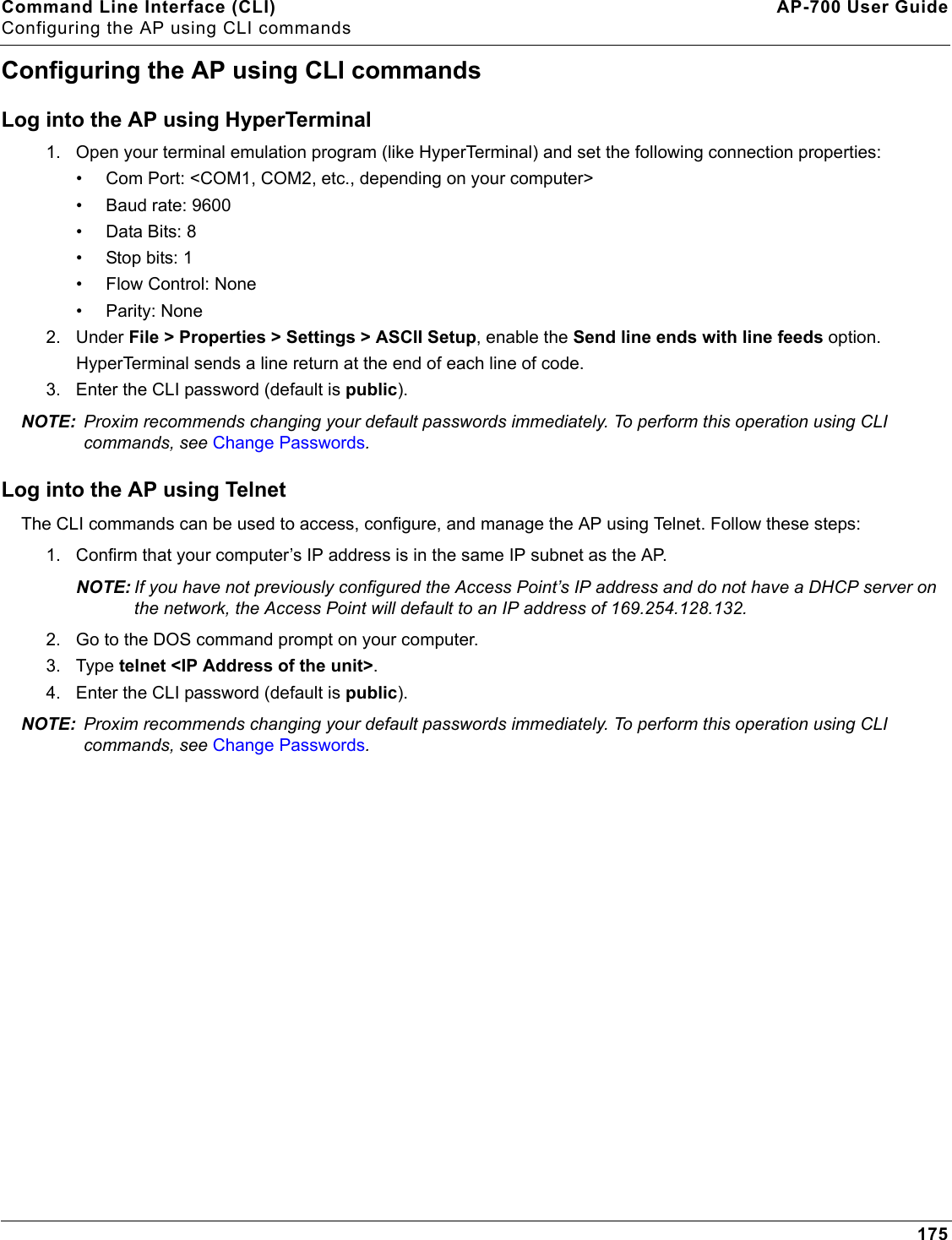
Troubleshooting AP-700 User GuideRecovery Procedures157[Device name]> show[Device name]> rebootThe AP will reboot and then download the image file. You should see downloading activity begin after a few seconds within the TFTP server’s status screen.8. When the download process is complete, configure the AP. Setting IP Address using Serial PortUse the following procedure to set an IP address over the serial port using the CLI. The network administrator typically provides the AP IP address.Hardware and Software Requirements• Standard straight-through serial data (RS-232) cable (not included with shipment). • ASCII Terminal software, such as HyperTerminal.Attaching the Serial Port Cable1. Connect one end of the serial cable to the AP and the other end to a serial port on your computer.2. Power on the computer and AP, if necessary.Initializing the IP Address using CLIAfter installing the serial port cable, you may use the CLI to communicate with the AP. CLI supports most generic terminal emulation programs, such as HyperTerminal (which is included with the Windows operating systems). In addition, many web sites offer shareware or commercial terminal programs you can download. Once the IP address has been assigned, you can use the HTTP interface or the CLI over Telnet to complete configuration.Follow these steps to assign the AP an IP address:1. Open your terminal emulation program (like HyperTerminal) and set the following connection properties:• Com Port: <COM1, COM2, etc., depending on your computer>• Baud rate: 9600•Data Bits: 8• Stop bits: 1• Flow Control: None• Parity: None2. Under File > Properties > Settings > ASCII Setup, enable the Send line ends with line feeds option. HyperTerminal sends a line return at the end of each line of code.3. Press the RESET button on the AP.The terminal display shows Power On Self Tests (POST) activity, and then displays a CLI prompt, similar to the example below. This process may take up to 90 seconds.[Device name]> Please enter password:4. Enter the CLI password (default is public). The terminal displays a welcome message and then the CLI Prompt:[Device name]> 5. Enter show ip. Network parameters appear:
Troubleshooting AP-700 User GuideRecovery Procedures158Figure 7-1 Result of “show ip” CLI Command6. Change the IP address and other network values using set and reboot CLI commands, similar to the example below (use your own IP address and subnet mask). Note that IP Address Type is set to Dynamic by default. If you have a DHCP server on your network, you should not need to manually configure the Access Point’s IP address; the Access Point will obtain an IP address from the network’s DHCP server during boot-up.After each entry the CLI reminds you to reboot; however wait to reboot until all commands have been entered. [Device name]> set ipaddrtype static[Device name]> set ipaddr <IP Address>[Device name]> set ipsubmask <IP Subnet Mask>[Device name]> set ipgw <Default Gateway IP Address>[Device name]> show ip (to confirm your new settings)[Device name]> reboot 07. After the AP reboots, verify the new IP address by reconnecting to the CLI and enter a show ip command. Alternatively, you can ping the AP from a network computer to confirm that the new IP address has taken effect.8. When the proper IP address is set, use the HTTP interface or CLI over Telnet to configure the rest of the unit’s operating parameters.
Troubleshooting AP-700 User GuideRelated Applications159Related ApplicationsRADIUS Authentication ServerIf you enabled RADIUS Authentication on the AP, make sure that your network’s RADIUS servers are operational. Otherwise, clients will not be able to log in. There are several reasons the authentication server services might be unavailable, here are two typical things to check:• Make sure you have the proper RADIUS authentication server information setup configured in the AP. Check the RADIUS Authentication Server’s Shared Secret and Destination Port number (default is 1812; for RADIUS Accounting, the default is 1813).• Make sure the RADIUS authentication server RAS setup matches the AP.TFTP ServerThe “Trivial File Transfer Protocol” (TFTP) server allows you to transfer files across a network. You can upload configuration files from the AP for backup or copying, and you can download configuration files or new software images. The TFTP software is located on the installation CD. If a TFTP server is not configured and running, you will not be able to download and upload images and configuration files to/from the AP. Remember that the TFTP server does not have to be local, so long as you have a valid TFTP IP address. Note that you do not need a TFTP server running unless you want to transfer files to or from the AP.After the TFTP server is installed:• Check to see that TFTP is configured to point to the directory containing the AP Image.• Make sure you have the proper TFTP server IP Address, the proper AP Image file name, and that the TFTP server is connected.• Make sure the TFTP server is configured to both Transmit and Receive files (on the TFTP server’s Security tab), with no automatic shutdown or time-out (on the Auto Close tab).
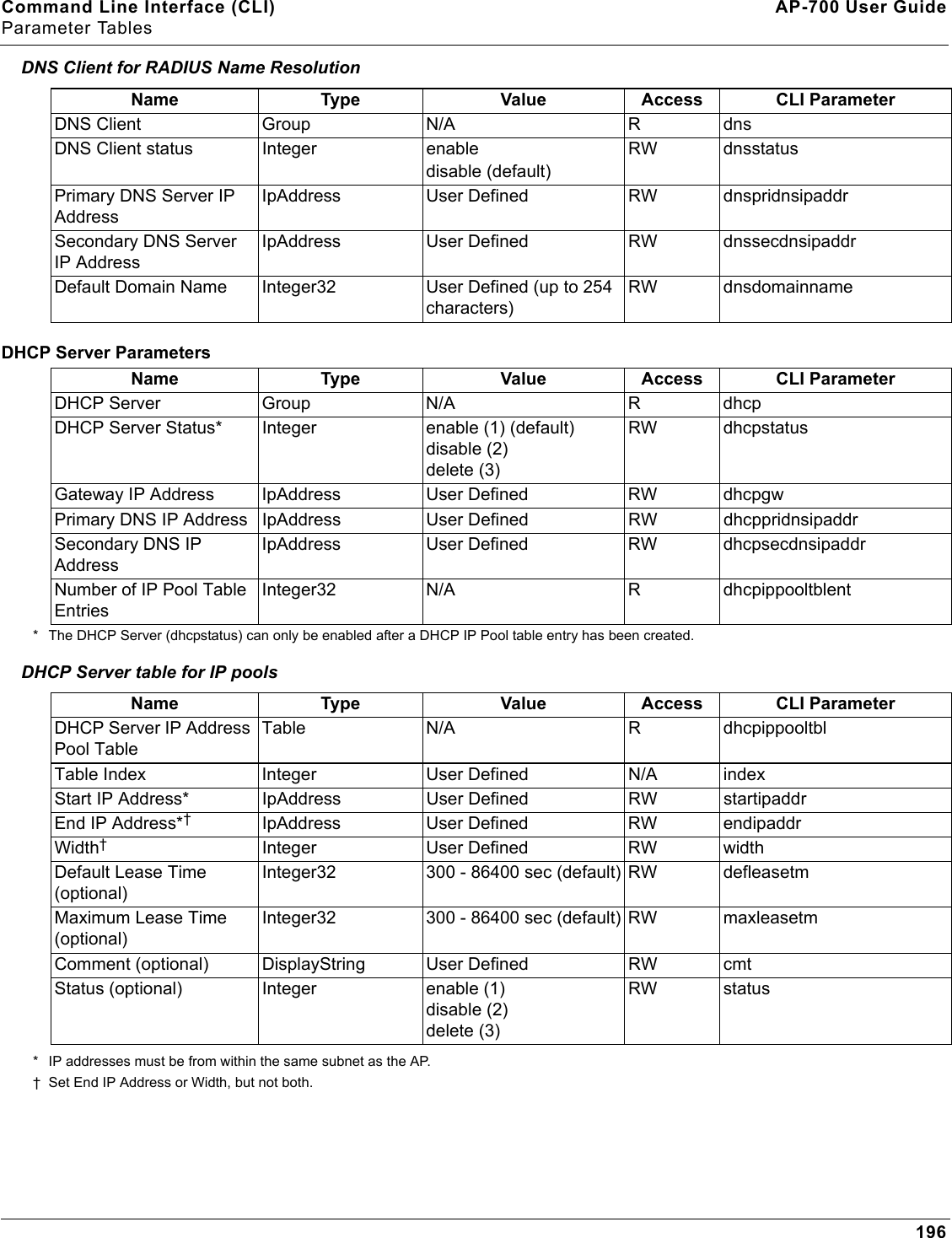
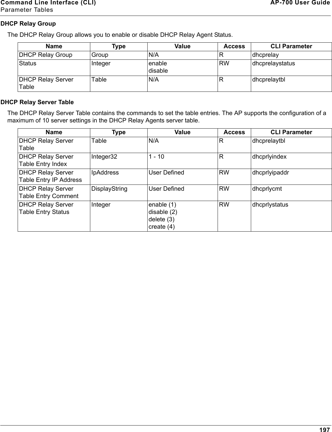
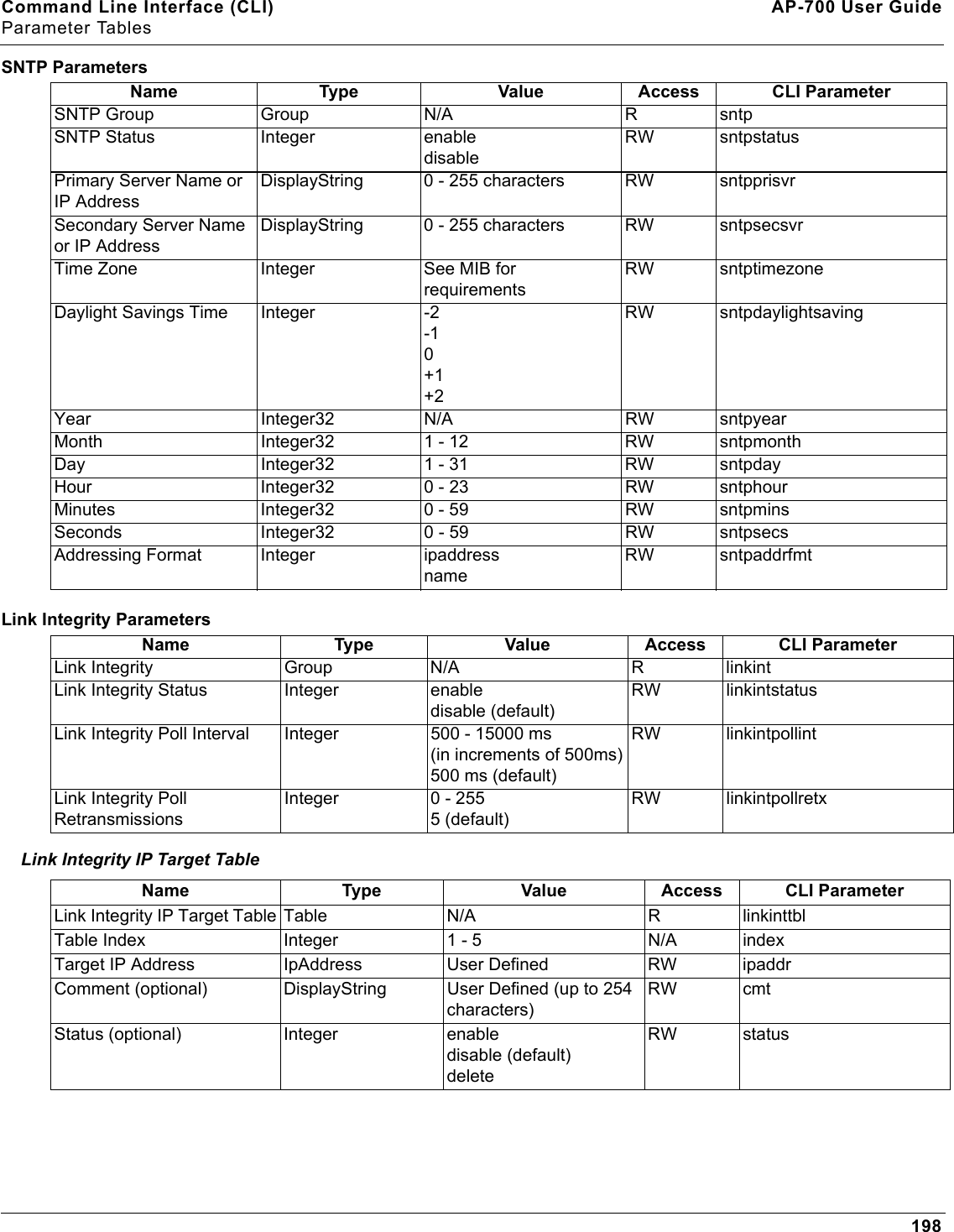
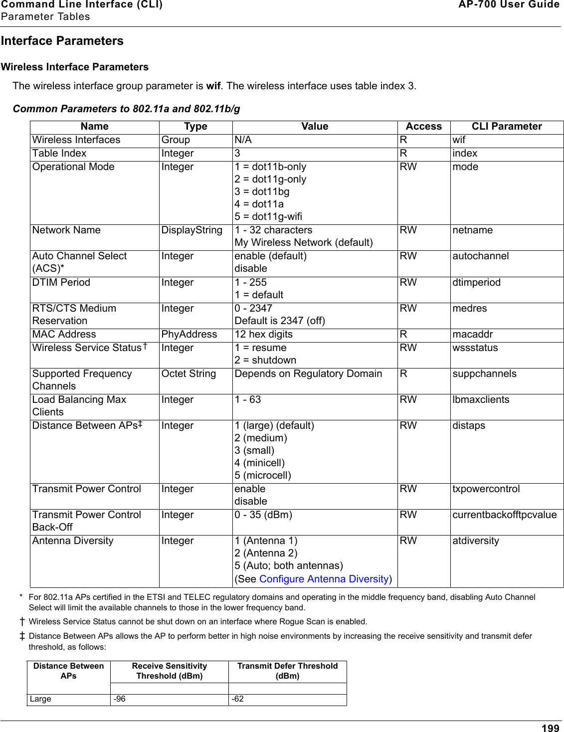
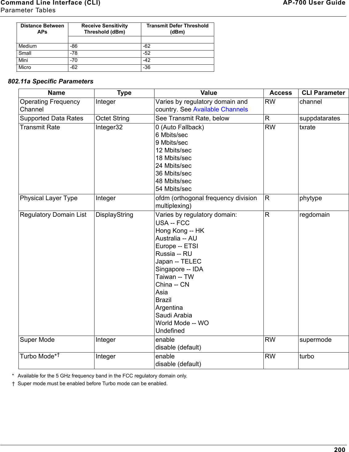
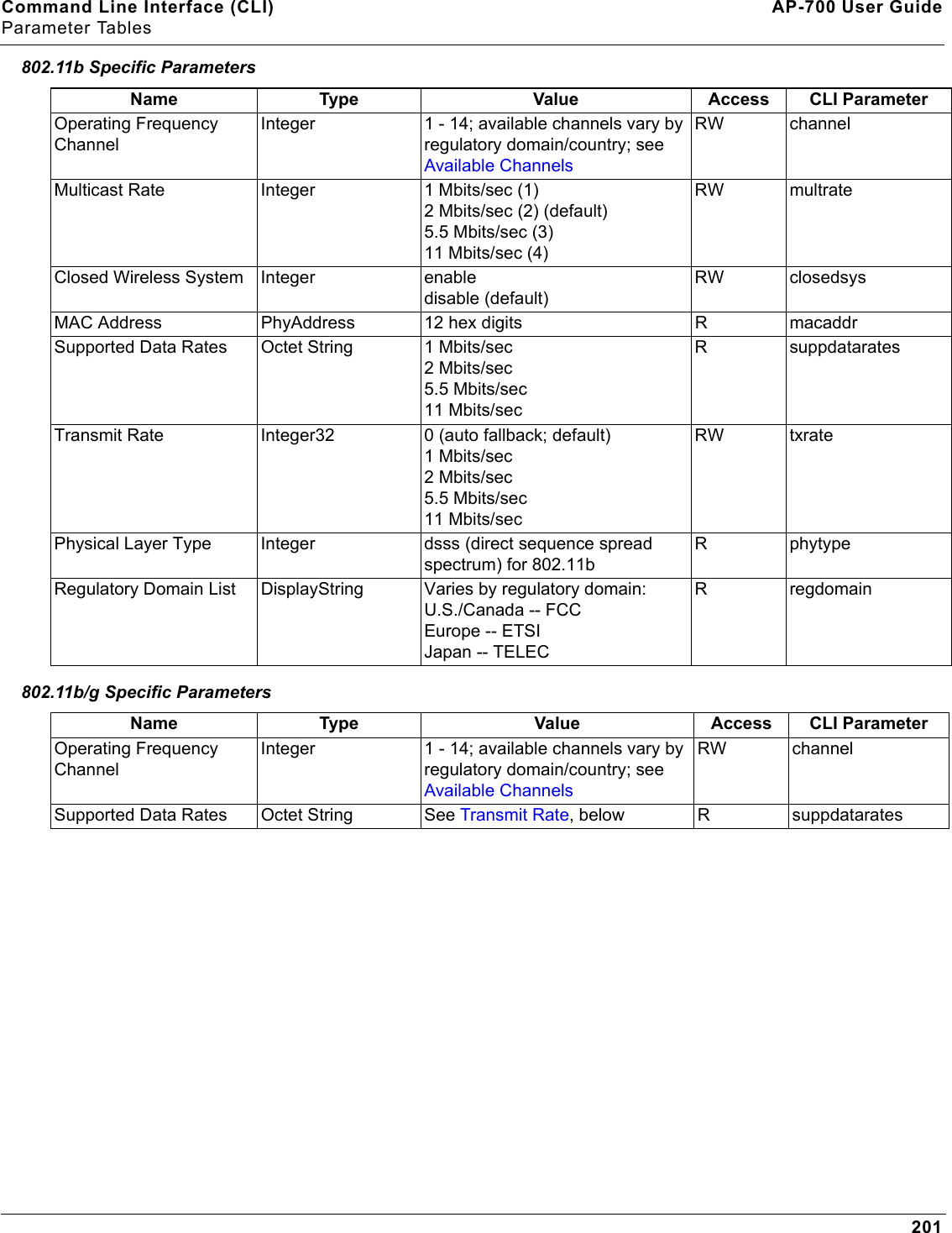
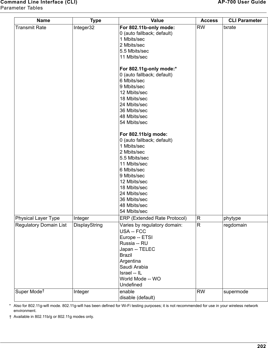
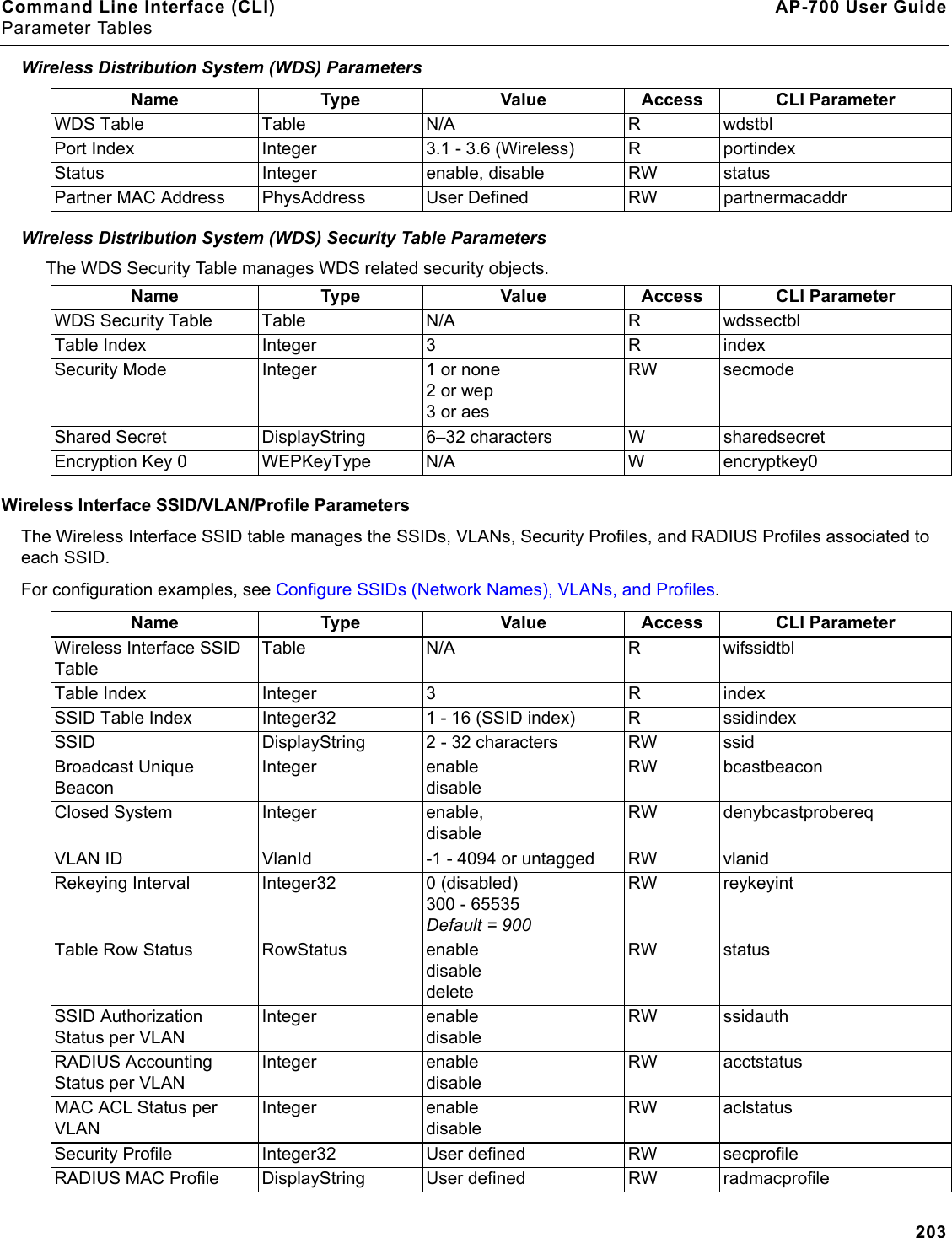
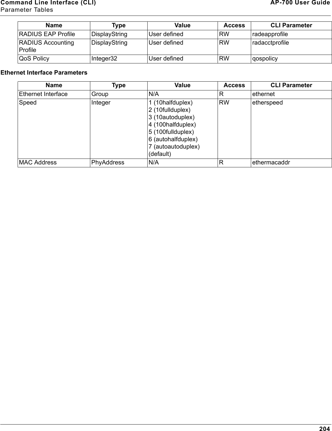
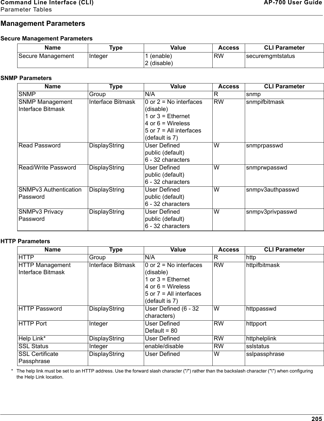
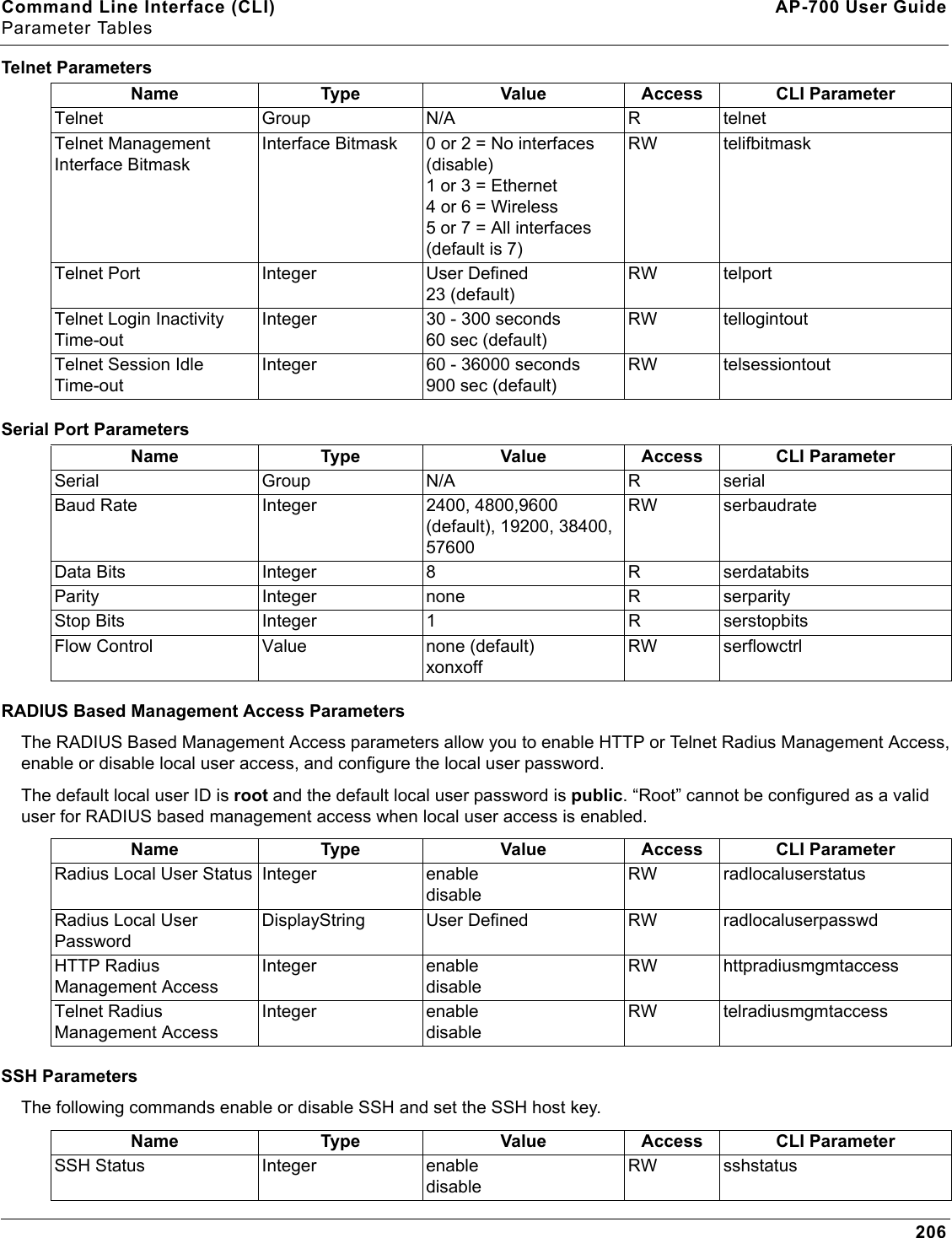
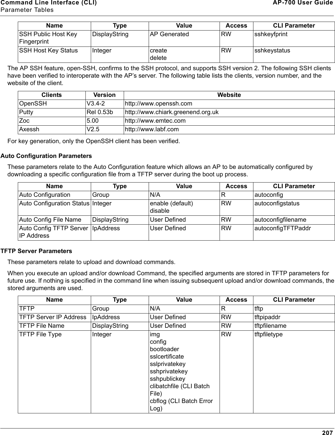
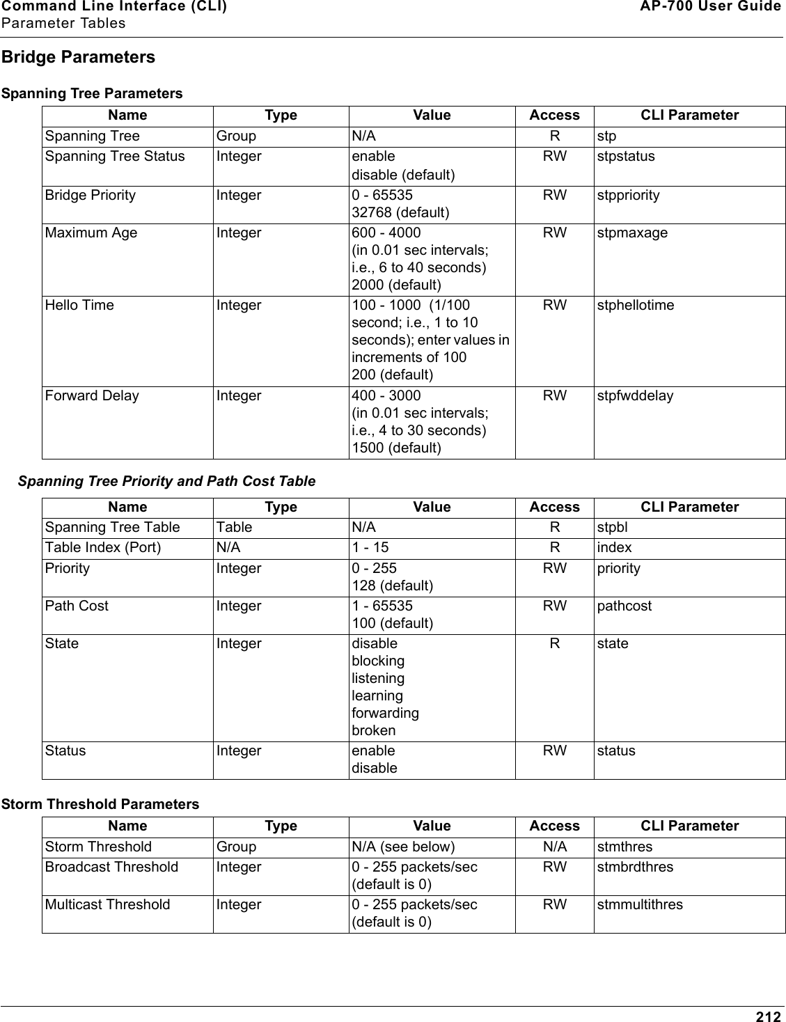
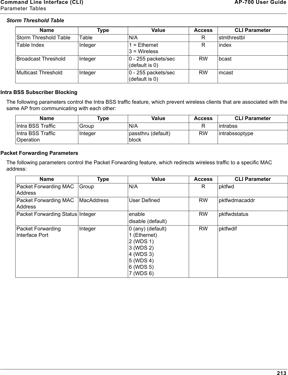
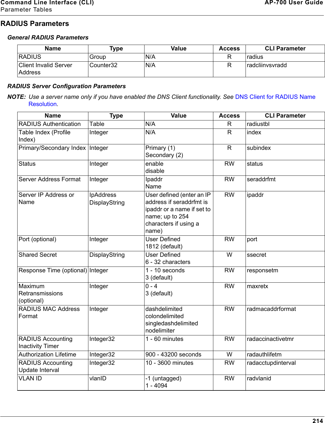
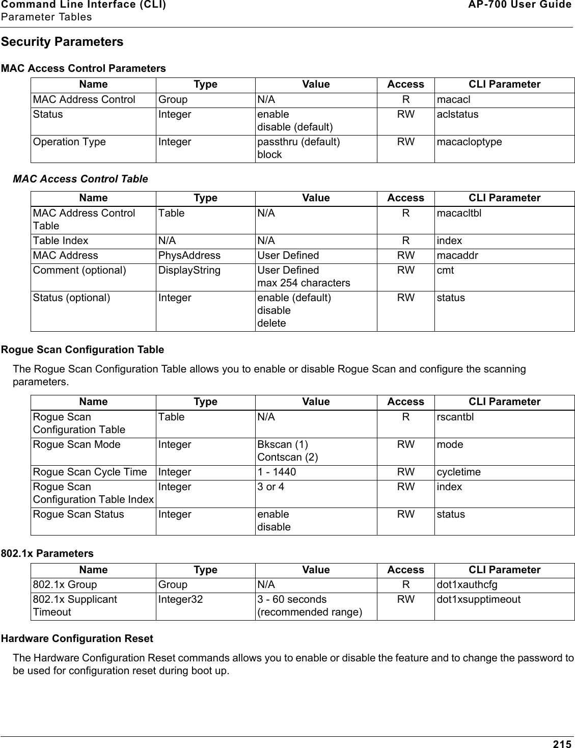
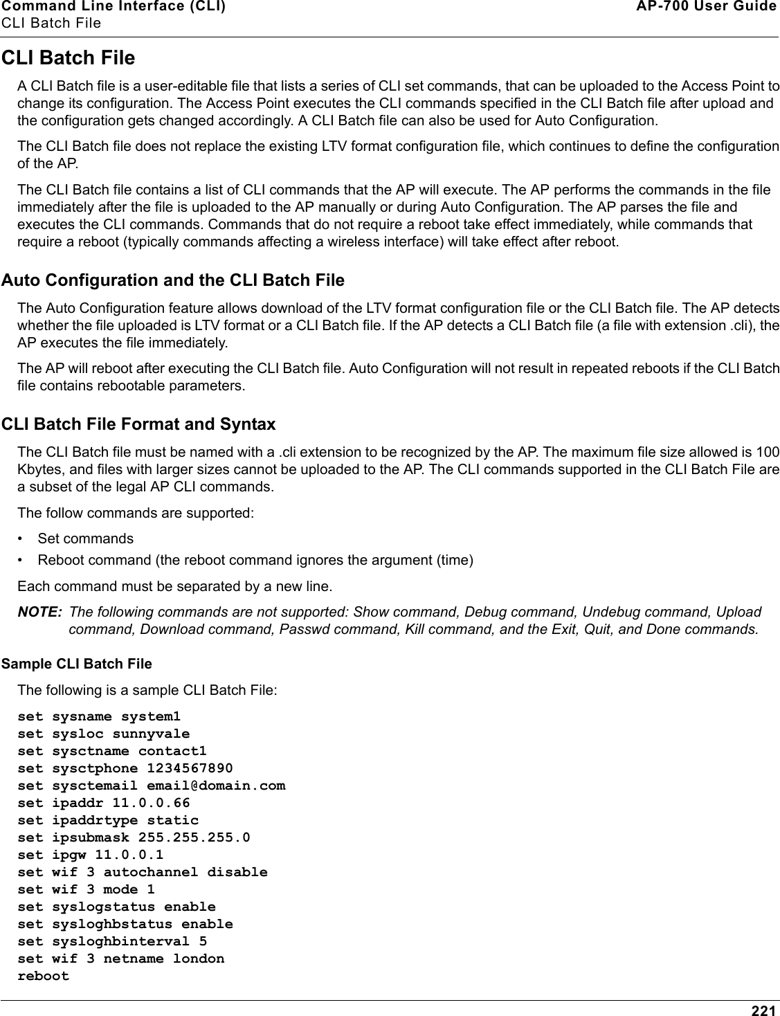
160AP-700 User GuideACommand Line Interface (CLI)This section discusses the following:•General Notes•Command Line Interface (CLI) Variations•CLI Command Types•Using Tables and Strings•Configuring the AP using CLI commands•CLI Monitoring Parameters•Parameter Tables•CLI Batch FileCLI commands can be used to initialize, configure, and manage the Access Point.• CLI commands may be entered in real time through a keyboard or submitted with CLI scripts.•A CLI Batch file is a user-editable configuration file that provides a user-friendly way to change the AP configuration through a file upload. The CLI Batch file is an ASCII file that facilitates Auto Configuration because it does not require the user to access one of the AP’s management interfaces to make configuration changes as is required with the proprietary LTV format configuration file. • The CLI is available through both the Serial Port interface and over the Ethernet interface using Telnet. NOTE: All CLI commands and parameters are case-sensitive.
Command Line Interface (CLI) AP-700 User GuideGeneral Notes161General NotesPrerequisite Skills and KnowledgeTo use this document effectively, you should have a working knowledge of Local Area Networking (LAN) concepts, network access infrastructures, and client-server relationships. In addition, you should be familiar with software setup procedures for typical network operating systems and servers.Notation Conventions• Computer prompts are shown as constant width type. For example: [Device-Name]>• Information that you input as shown is displayed in bold constant width type. For example: [Device name]> set ipaddr 10.0.0.12• The names of keyboard keys, software buttons, and field names are displayed in bold type. For example: Click the Configure button.• Screen names are displayed in bold italics. For example, the System Status screen.Important Terminology• Configuration Files - Database files containing the current Access Point configuration. Configuration items include the IP Address and other network-specific values. Config files may be downloaded to the Access Point or uploaded for backup or troubleshooting.• Download vs. Upload - Downloads transfer files to the Access Point. Uploads transfer files from the Access Point. The TFTP server performs file transfers in both directions.• Group - A logical collection of network parameter information. For example, the System Group is composed of several related parameters. Groups can also contain Tables. All items for a given Group can be displayed with a show <Group> CLI Command.• Image File - The Access Point software executed from RAM. To update an Access Point you typically download a new Image File. This file is often referred to as the “AP Image”.• Parameter - A fundamental network value that can be displayed and may be changeable. For example, the Access Point must have a unique IP Address and the Wireless interface must be assigned an SSID. Change parameters with the CLI set Command, and view them with the CLI show Command.• Table - Tables hold parameters for several related items. For example, you can add several potential managers to the SNMP Table. All items for a given Table can be displayed with a show <Table> CLI Command.• TFTP - Refers to the TFTP Server, used for file transfers. Navigation and Special KeysThis CLI supports the following navigation and special key functions to move the cursor along the prompt line.Key Combination OperationDelete or Backspace Delete previous characterCtrl-A Move cursor to beginning of lineCtrl-E Move cursor to end of lineCtrl-F Move cursor forward one characterCtrl-B Move cursor back one characterCtrl-D Delete the character the cursor is onCtrl-U Delete all text to left of cursorCtrl-P Go to the previous line in the history bufferCtrl-N Go to the next line in the history bufferCtrl-W Delete the previous word
Command Line Interface (CLI) AP-700 User GuideGeneral Notes162CLI Error MessagesThe following table describes the error messages associated with improper inputs or expected CLI behavior.Tab Complete the command line? List available commandsError Message DescriptionSyntax Error Invalid syntax entered at the command prompt.Invalid Command A non-existent command has been entered at the command prompt.Invalid Parameter Name An invalid parameter name has been entered at the command prompt.Invalid Parameter Value An invalid parameter value has been entered at the command prompt.Invalid Table Index An invalid table index has been entered at the command prompt.Invalid Table Parameter An invalid table parameter has been entered at the command prompt.Invalid Table Parameter Value An invalid table parameter value has been entered at the command prompt.Read Only Parameter User is attempting to configure a read-only parameter.Incorrect Password An incorrect password has been entered in the CLI login prompt.Download Unsuccessful The download operation has failed due to incorrect TFTP server IP Address or file name.Upload Unsuccessful The upload operation has failed due to incorrect TFTP server IP Address or file name.Key Combination Operation
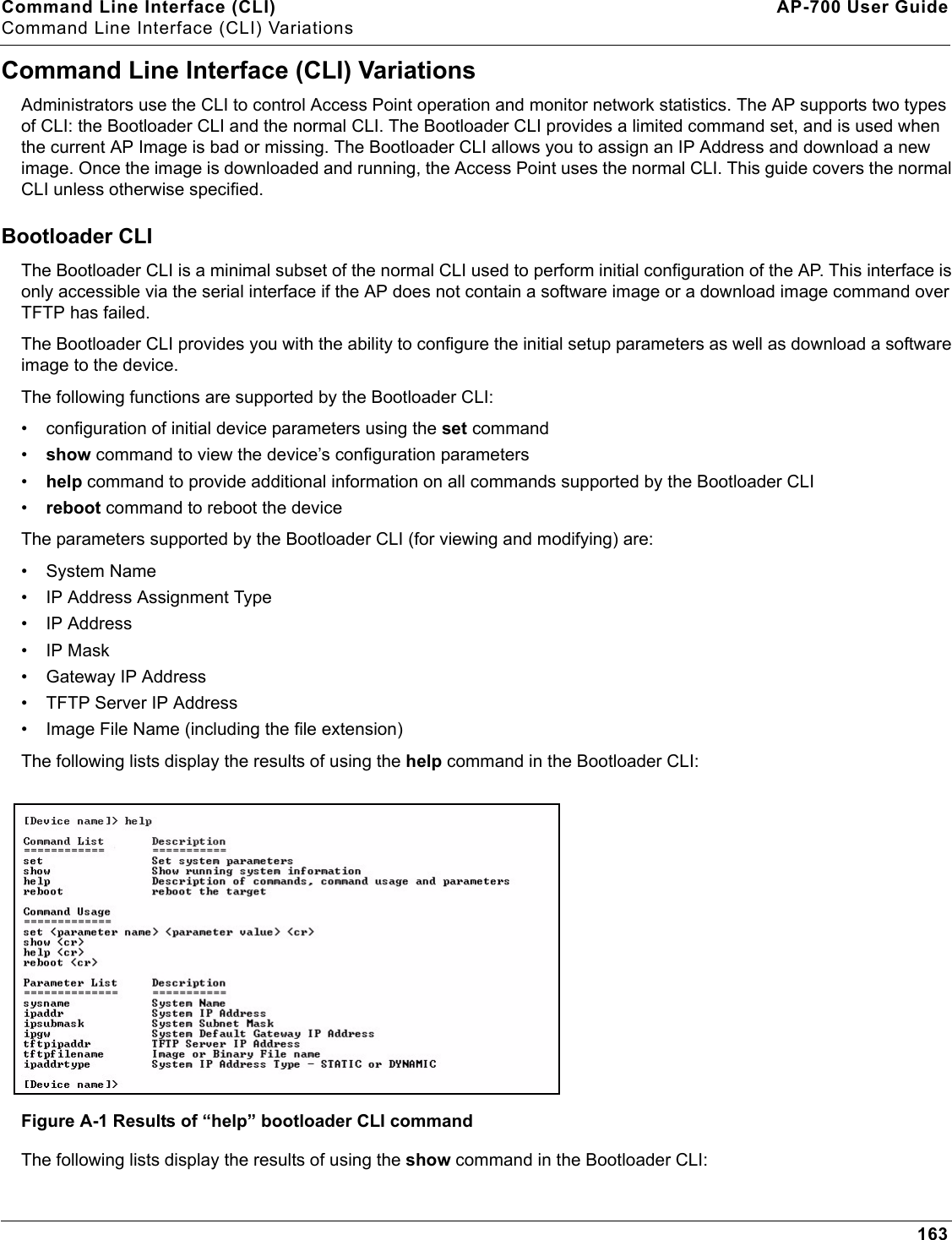
Command Line Interface (CLI) AP-700 User GuideCommand Line Interface (CLI) Variations163Command Line Interface (CLI) VariationsAdministrators use the CLI to control Access Point operation and monitor network statistics. The AP supports two types of CLI: the Bootloader CLI and the normal CLI. The Bootloader CLI provides a limited command set, and is used when the current AP Image is bad or missing. The Bootloader CLI allows you to assign an IP Address and download a new image. Once the image is downloaded and running, the Access Point uses the normal CLI. This guide covers the normal CLI unless otherwise specified.Bootloader CLIThe Bootloader CLI is a minimal subset of the normal CLI used to perform initial configuration of the AP. This interface is only accessible via the serial interface if the AP does not contain a software image or a download image command over TFTP has failed.The Bootloader CLI provides you with the ability to configure the initial setup parameters as well as download a software image to the device. The following functions are supported by the Bootloader CLI:• configuration of initial device parameters using the set command•show command to view the device’s configuration parameters•help command to provide additional information on all commands supported by the Bootloader CLI•reboot command to reboot the deviceThe parameters supported by the Bootloader CLI (for viewing and modifying) are:• System Name• IP Address Assignment Type• IP Address•IP Mask• Gateway IP Address• TFTP Server IP Address• Image File Name (including the file extension)The following lists display the results of using the help command in the Bootloader CLI:Figure A-1 Results of “help” bootloader CLI commandThe following lists display the results of using the show command in the Bootloader CLI:
Command Line Interface (CLI) AP-700 User GuideCommand Line Interface (CLI) Variations164Figure A-2 Results of “show” bootloader CLI command
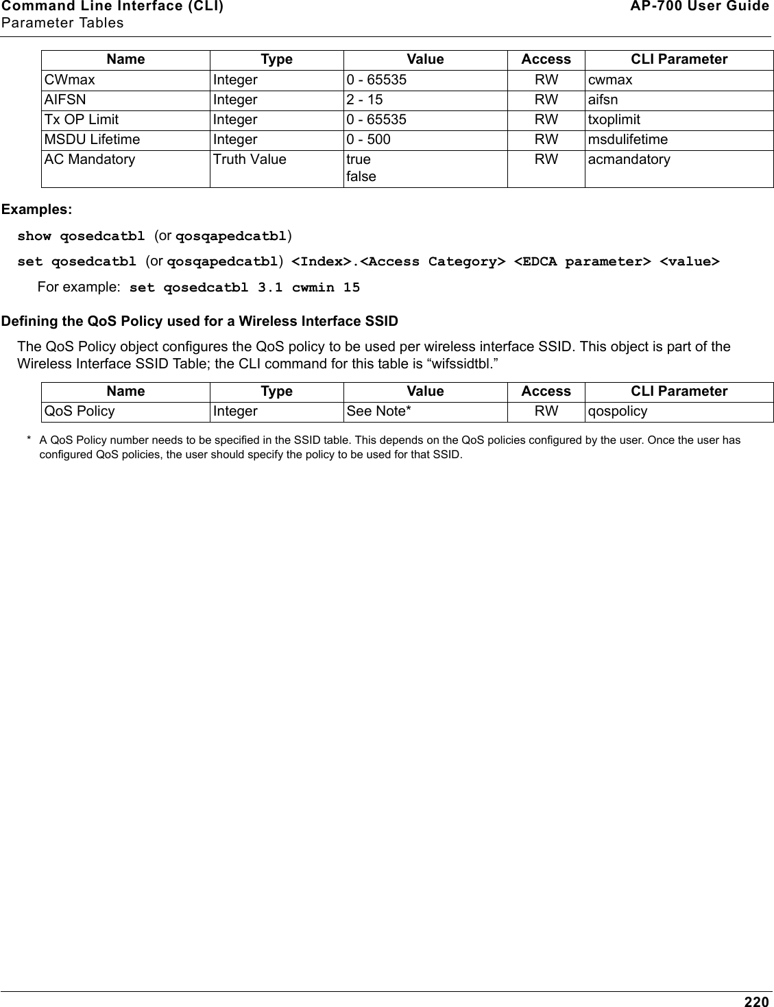
Command Line Interface (CLI) AP-700 User GuideCLI Command Types165CLI Command TypesThis guide divides CLI Commands into two categories: Operational and Parameter Controls.Operational CLI CommandsThese commands affect Access Point behavior, such as downloading, rebooting, and so on. After entering commands (and parameters, if any) press the Enter key to execute the Command Line.Operational commands include:•?: Typing a question mark lists CLI Commands or parameters, depending on usage (you do not need to type Enter after typing this command)•done, exit, quit: Terminates the CLI session•download: Uses a TFTP server to download “image” files, “config” files, “bootloader upgrade” files, a “license” file, “SSL certificates”, “SSL private keys”, “SSH public keys”, “SSH private keys”, or “CLI Batch Files” to the Access Point•help: Displays general CLI help information or command help information, such as command usage and syntax•history: Remembers commands to help avoid re-entering complex statements•passwd: Sets the Access Point’s CLI password•reboot: Reboots the Access Point in the specified time•search: Lists the parameters in a specified Table•upload: Uses TFTP server to upload “config” files from Access Point to TFTP default directory or specified path? (List Commands) This command can be used in a number of ways to display available commands and parameters.The following table lists each operation and provides a basic example. Following the table are detailed examples and display results for each operation. Example 1. Display Command listTo display the Command List, enter ?.[Device-Name]>?Figure A-3 Result of “?” CLI commandOperation Basic ExampleDisplay the Command List (Example 1) [Device-Name]>?Display commands that start with specified letters (Example 2)[Device-Name]>s?Display parameters for set and show Commands (Examples 3a and 3b)[Device-Name]>set ?[Device-Name]>show ipa?Prompt to enter successive parameters for Commands (Example 4)[Device-Name]>download ?
Command Line Interface (CLI) AP-700 User GuideCLI Command Types166Example 2. Display specific CommandsTo show all commands that start with specified letters, enter one or more letters, then ? with no space between letters and ?.[Device-Name]>s?Figure A-4 Result of “s?” CLI commandExample 3. Display parameters for set and showExample 3a allows you to see every possible parameter for the set (or show) commands. Notice from example 3a that the list is very long. Example 3b shows how to display a subset of the parameters based on initial parameter letters.Example 3a. Display every parameter that can be changed[Device-Name]>set ? Figure A-5 Result of “set ?” CLI commandExample 3b. Display parameters based on letter sequenceThis example shows entries for parameters that start with the letter “i”. The more letters you enter, the fewer the results returned. Notice that there is no space between the letters and the question mark.[Device-Name]> show ipa? Figure A-6 Result of “show ipa?” CLI command[Device-Name]> show iparp?....
Command Line Interface (CLI) AP-700 User GuideCLI Command Types167 Figure A-7 Result of “show iparp?” CLI commandExample 4. Display Prompts for Successive ParametersEnter the command, a space, and then ?. Then, when the parameter prompt appears, enter the parameter value. The parameter is changed and a new CLI line is echoed with the new value (in the first part of the following example, the value is the IP Address of the TFTP server).After entering one parameter, you may add another ? to the new CLI line to see the next parameter prompt, and so on until you have entered all of the required parameters. The following example shows how this is used for the download Command. The last part of the example shows the completed download Command ready for execution.[Device-Name]> download ?<TFTP IP Address>[Device-Name]> download 192.168.0.101 ?<File Name>[Device-Name]> download 192.168.0.101 apimage ?<file type (config/img/bootloader)>[Device-Name]> download 192.168.0.101 apimage img <CR>done, exit, quit Each of the following commands ends a CLI session: [Device-Name]> done[Device-Name]> exit[Device-Name]> quitdownload Downloads the specified file from a TFTP server to the Access Point. Executing download in combination with the asterisks character (“*”) will make use of the previously set TFTP parameters. Executing download without parameters will display command help and usage information.1. Syntax to download a file:[Device-Name]>download <tftp server address> <path and filename> <file type>Example:[Device-Name]>download 192.168.1.100 APImage2 img2. Syntax to display help and usage information:[Device-Name]>download3.  Syntax to execute the download Command using previously set (stored) TFTP Parameters:[Device-Name]>download *
Command Line Interface (CLI) AP-700 User GuideCLI Command Types168helpDisplays instructions on using control-key sequences for navigating a Command Line and displays command information and examples.1. Using help as the only argument:[Device-Name]>helpFigure A-8 Results of “help” CLI command2. Complete command description and command usage can be provided by:[Device-Name]>help <command name>[Device-Name]><command name> helphistory Shows content of Command History Buffer. The Command History Buffer stores command statements entered in the current session. To avoid re-entering long command statements, use the keyboard “up arrow” (Ctrl-P) and “down arrow” (Ctrl-N) keys to recall previous statements from the Command History Buffer. When the desired statement reappears, press the Enter key to execute, or you may edit the statement before executing it.[Device-Name]> historypasswd Changes the CLI Password. [Device-Name]> passwd oldpassword newpassword newpasswordreboot Reboots Access Point after specified number of seconds. Specify a value of 0 (zero) for immediate reboot.[Device-Name]> reboot 0[Device-Name]> reboot 30
Command Line Interface (CLI) AP-700 User GuideCLI Command Types169search Lists the parameters supported by the specified table. This list corresponds to the table information displayed in the HTTP interface. In this example, the CLI returns the list of parameters that make up an entry in the IP Access Table. [Device-Name]> search mgmtipaccesstblFigure A-9 Results of “search mgmtipaccesstbl” CLI commanduploadUploads a text-based configuration file from the AP to the TFTP Server. Executing upload with the asterisk character (“*”) will make use of the previously set/stored TFTP parameters. Executing upload without parameters will display command help and usage information. 1. Syntax to upload a file:[Device-Name]>upload <tftp server address> <path and filename> <filetype>Example:[Device-Name]>upload 192.168.1.100 APconfig.sys config2. Syntax to display help and usage information:[Device-Name]>help upload3. Syntax to execute the upload command using previously set (stored) TFTP Parameters:[Device-Name]>upload *Parameter Control CommandsThe following sections cover the two Parameter Control Commands (show and set) and include several tables showing parameter properties. These commands allow you to view (show) all parameters and statistics and to change (set) parameters. •show: To see any Parameter or Statistic value, you can specify a single parameter, a Group, or a Table. •set: Use this CLI Command to change parameter values. You can use a single CLI statement to modify Tables, or you can modify each parameter separately. “show” CLI CommandDisplays the value of the specified parameter, or displays all parameter values of a specified group (parameter table). Groups contain Parameters and Tables. Tables contain parameters for a series of similar entities.To see a definition and syntax example, type only show and then press the Enter key. To see a list of available parameters, enter a question mark (?) after show (example: show ?). Syntax:[Device-Name]>show <parameter>[Device-Name]>show <group>[Device-Name]>show <table>Examples:[Device-Name]>show ipaddr
Command Line Interface (CLI) AP-700 User GuideCLI Command Types170[Device-Name]>show network[Device-Name]>show mgmtipaccesstbl“set” CLI CommandSets (modifies) the value of the specified parameter. To see a definition and syntax example, type only set and then press the Enter key. To see a list of available parameters, enter a space, then a question mark (?) after set (example: set?). Syntax:[Device-Name]>set <parameter> <value> [Device-Name]>set <table> <index> <argument 1> <value 1> ... <argument N> <value N>Example:[Device-Name]>set sysloc “Main Lobby”[Device-Name]>set mgmtipaccesstbl 0 ipaddr 10.0.0.10 ipmask 255.255.0.0 Configuring Objects that Require RebootCertain objects supported by the Access Point require a device reboot in order for the changes to take effect. In order to inform the end-user of this behavior, the CLI provides informational messages when the user has configured an object that requires a reboot. The following messages are displayed as a result of the configuring such object or objects.Example 1: Configuring objects that require the device to be rebootedThe following message is displayed every time the user has configured an object that requires the device to be rebooted.[Device-Name]>set ipaddr 135.114.73.10The following elements require rebootipaddrExample 2: Executing the “exit”, “quit”, or “done” commands when an object that requires reboot has been configuredIn addition to the above informational message, the CLI also provides a message as a result of the exit, quit, or done command if changes have been made to objects that require reboot. If you make changes to objects that require reboot and execute the exit command the following message is displayed:[Device-Name]>exit<CR> OR quit<CR> OR done<CR>Modifications have been made to parameters that require the device to be rebooted. These changes will only take effect after the next reboot.“set” and “show” Command ExamplesIn general, you will use the CLI show Command to view current parameter values and use the CLI set Command to change parameter values. As shown in the following examples, parameters may be set individually or all parameters for a given table can be set with a single statement. Example 1 - Set the Access Point IP Address ParameterSyntax:[Device-Name]>set <parameter name> <parameter value> Example:[Device-Name]> set ipaddr 10.0.0.12IP Address will be changed when you reboot the Access Point. The CLI reminds you when rebooting is required for a change to take effect. To reboot immediately, enter reboot 0 (zero) at the CLI prompt.
Command Line Interface (CLI) AP-700 User GuideCLI Command Types171Example 2 - Create a table entry or rowUse 0 (zero) as the index to a table when creating an entry. When creating a table row, only the mandatory table elements are required (comment is usually an optional table element). For optional table elements, the default value is generally applied if you do not specify a value.Syntax:[Device-Name]>set <table name> <table index> <element 1> <value 1> …      <element n> <value n>Example:[Device-Name]> set mgmtipaccesstbl 0 ipaddr 10.0.0.10 ipmask 255.255.0.0A new table entry is created for IP address 10.0.0.10 with a 255.255.0.0 subnet mask.Example 3 - Modify a table entry or rowUse the index to be modified and the table elements you would like to modify. For example, suppose the IP Access Table has one entry and you wanted to modify the IP address:[Device-Name]>set mgmtipaccesstbl 1 ipaddr 10.0.0.11You can also modify several elements in the table entry. Enter the index number and specific table elements you would like to modify. (Hint: Use the search Command to see the elements that belong to the table.)[Device-Name]>set mgmtipaccesstbl 1 ipaddr 10.0.0.12 ipmask 255.255.255.248           cmt “First Row”Example 4 - Enable, Disable, or Delete a table entry or rowThe following example illustrates how to manage the second entry in a table.Syntax:[Device-Name]>set <Table> index status <enable, disable, delete>[Device-Name]>set <Table> index status <1=enable, 2=disable, 3=delete>Example:[Device-Name]>set mgmtipaccesstbl 2 status enable[Device-Name]>set mgmtipaccesstbl 2 status disable[Device-Name]>set mgmtipaccesstbl 2 status delete[Device-Name]>set mgmtipaccesstbl 2 status 2NOTE: You may need to enable a disabled table entry before you can change the entry’s elements.Example 5 - Show the Group ParametersThis example illustrates how to view all elements of a group or table.Syntax:[Device-Name]> show <group name>Example:[Device-Name]>show networkThe CLI displays network group parameters. Note show network and show ip return the same data.
Command Line Interface (CLI) AP-700 User GuideCLI Command Types172Figure A-10 Results of “show network” and “show ip” CLI CommandsExample 6 - Show Individual and Table Parameters1. View a single parameter.Syntax:[Device-Name]>show <parameter name>Example:[Device-Name]> show ipaddrDisplays the Access Point IP address.Figure A-11 Result of “show ipaddr” CLI Command2. View all parameters in a table.Syntax:[Device-Name]> show <table name>Example: [Device-Name]> show mgmtipaccesstblThe CLI displays the IP Access Table and its entries.
Command Line Interface (CLI) AP-700 User GuideUsing Tables and Strings173Using Tables and StringsWorking with TablesEach table element (or parameter) must be specified, as in the example below. [Device-Name]>set mgmtipaccesstbl 0 ipaddr 10.0.0.10 ipmask 255.255.0.0Below are the rules for creating, modifying, enabling/disabling, and deleting table entries.•Creation– The table name is required.– The table index is required – for table entry/instance creation the index is always zero (0).– The order in which the table arguments or objects are entered in not important.– Parameters that are not required can be omitted, in which case they will be assigned the default value.• Modification– The table name is required.– The table index is required – to modify the table, “index” must be the index of the entry to be modified.– Only the table objects that are to be modified need to be specified. Not all the table objects are required.– If multiple table objects are to be modified the order in which they are entered is not important.– If the entire table entry is to be modified, all the table objects have to be specified.• Enabling/Disabling– The table name is required.– The table index is required – for table enabling/disabling the index should be the index of the entry to be enabled/disabled.– The entry’s new state (either “enable” or “disable”) is required.• Deletion– The table name is required.– The table index is required – for table deletion the index should be the index of the entry to be deleted.– The word “delete” is required.Using StringsSince there are several string objects supported by the AP, a string delimiter is required for the strings to be interpreted correctly by the command line parser. For this CLI implementation, the single quote or double quote character can be used at the beginning and at the end of the string. For example:[Device-Name]> set sysloc Lobby - Does not need quote marks[Device-Name]> set sysloc “Front Lobby” - Requires quote marks. The scenarios supported by this CLI are:“My Desk in the office” Double Quotes‘My Desk in the office’ Single Quotes“My ‘Desk’ in the office” Single Quotes within Double Quotes‘My “Desk” in the office’ Double Quotes within Single Quotes“Daniel’s Desk in the office” One Single Quote within Double Quotes‘Daniel”s Desk in the office’ One Double Quote within Single Quotes
Command Line Interface (CLI) AP-700 User GuideUsing Tables and Strings174The string delimiter does not have to be used for every string object. The single quote or double quote only has to be used for string objects that contain blank space characters. If the string object being used does not contain blank spaces, then the string delimiters, single or double quotes, mentioned in this section are not required.
Command Line Interface (CLI) AP-700 User GuideConfiguring the AP using CLI commands175Configuring the AP using CLI commandsLog into the AP using HyperTerminal1. Open your terminal emulation program (like HyperTerminal) and set the following connection properties:• Com Port: <COM1, COM2, etc., depending on your computer>• Baud rate: 9600• Data Bits: 8• Stop bits: 1• Flow Control: None• Parity: None2. Under File > Properties > Settings > ASCII Setup, enable the Send line ends with line feeds option. HyperTerminal sends a line return at the end of each line of code.3. Enter the CLI password (default is public).NOTE: Proxim recommends changing your default passwords immediately. To perform this operation using CLI commands, see Change Passwords.Log into the AP using TelnetThe CLI commands can be used to access, configure, and manage the AP using Telnet. Follow these steps:1. Confirm that your computer’s IP address is in the same IP subnet as the AP.NOTE: If you have not previously configured the Access Point’s IP address and do not have a DHCP server on the network, the Access Point will default to an IP address of 169.254.128.132.2. Go to the DOS command prompt on your computer.3. Type telnet <IP Address of the unit>.4. Enter the CLI password (default is public).NOTE: Proxim recommends changing your default passwords immediately. To perform this operation using CLI commands, see Change Passwords.
Command Line Interface (CLI) AP-700 User GuideConfiguring the AP using CLI commands176Set Basic Configuration Parameters using CLI CommandsThere are a few basic configuration parameters that you may want to setup right away when you receive the AP. For example:•Set System Name, Location and Contact Information•Set Static IP Address for the AP•Download an AP Configuration File from your TFTP Server•Set up Auto Configuration•Set Network Names for the Wireless Interface•Enable 802.11d Support and Set the Country Code•Enable and Configure TX Power Control for the Wireless Interface•Configure SSIDs (Network Names), VLANs, and Profiles•Download an AP Configuration File from your TFTP Server•Backup your AP Configuration FileSet System Name, Location and Contact InformationNOTE: System name must:•Contain only letters, numbers, and hyphens.•Be limited to 31 characters.•Not begin with a number or hyphen.•Not contain blank spaces. [Device-Name]>set sysname <Name> sysloc <Unit Location>[Device-Name]>set sysctname <Contact Name>[Device-Name]>set sysctphone <Contact Phone Number> sysctemail <Contact E-mail address>[Device-Name]>show systemFigure A-12 Result of “show system” CLI CommandSet Static IP Address for the APNOTE: The IP Subnet Mask of the AP must match your network’s Subnet Mask.[Device-Name]>set ipaddrtype static [Device-Name]>set ipaddr <fixed IP address of unit>[Device-Name]>set ipsubmask <IP Mask>[Device-Name]>set ipgw <gateway IP address>[Device-Name]>show networkChange Passwords[Device-Name]>passwd <Old Password> <New Password> <Confirm Password> (CLI password)[Device-Name]>set httppasswd <New Password> (HTTP interface password)
Command Line Interface (CLI) AP-700 User GuideConfiguring the AP using CLI commands177[Device-Name]>set snmprpasswd <New Password> (SNMP read password)[Device-Name]>set snmprwpasswd <New Password> (SNMP read/write)[Device-Name]>set snmpv3authpasswd <New Password> (SNMPv3 authentication password)[Device-Name]>set snmpv3privpasswd <New Password> (SNMPv3 privacy password)[Device-Name]>reboot 0CAUTION: Proxim strongly urges you to change the default passwords to restrict access to your network devices to authorized personnel. If you lose or forget your password settings, you can always perform the Soft Reset to Factory Defaults.Set Network Names for the Wireless Interface[Device-Name]>set wif 3 netname <Network Name (SSID) for wireless interface>[Device-Name]>show wifFigure A-13 Results of “show wif” CLI command for an APEnable 802.11d Support and Set the Country CodeNOTE: On APs with model numbers ending in -WD, these commands are not available.Perform the following command to enable 802.11d IEEE 802.11d support for additional regulatory domains.[Device-Name]>set wif 3 dot11dstatus <enable/disable>Perform the following command to set a country code:[Device-Name]>set syscountrycode <country code>Select a country code from the following table, derived from ISO 3166. Available countries will vary based on regulatory domain. Refer to the ISO/IEC 3166-1 CountryCode drop-down menu on the Configure > Interfaces > Operational Mode page; this menu contains a list of all the available countries in your regulatory domain.NOTE: If you select a country code that is not supported in your regulatory domain, clients may attempt to connect to a channel that is not supported by your AP. Country Code Country Code Country CodeAlgeria DZ Honduras HN Panama PAAlbania AL Hong Kong HK Papua New Guinea PGArgentina AR Hungary HU Peru PE
Command Line Interface (CLI) AP-700 User GuideConfiguring the AP using CLI commands178Enable and Configure TX Power Control for the Wireless InterfaceThe TX Power Control feature lets the user configure the transmit power level of the card in the AP.Armenia AM Iceland IS  Philippines PHAustralia AU India IN  Poland PLAustria AT Indonesia ID Portugal PTAzerbaijan AZ  Ireland 5.8 GHz I1 Puerto Rico PRBahrain BH Israel IL Qatar QABelarus BY Italy IT Romania ROBelgium BE Jamaica JM Russia RUBelize BZ Japan JP Samoa WSBolivia BO Japan2 J2 Saudi Arabia SABrazil BR Jordan JO Singapore SGBrunei Darussalam BN  Kazakhstan KZ Slovak Republic SKBulgaria BG North Korea KP Slovenia SICanada CA  Korea Republic KR South Africa ZAChile CL  Korea Republic2 K2 South Korea KRChina CN Kuwait KW Spain ESColombia CO Latvia LV Sweden SECosta Rica CR  Lebanon LB Switzerland CHCroatia HR Liechtenstein LI Syria SYCyprus CY Lithuania LT Taiwan TWCzech Republic CZ  Luxembourg LU Thailand THDenmark DK Macau MO Turkey TRDominican Republic DO  Macedonia MK Ukraine UAEcuador EC  Malaysia MY United Arab Emirates AEEgypt EG Malta MT United Kingdom GBEl Salvador SV Mexico MX United Kingdom 5.8 GHz G1Estonia EE Monaco MC United States USFinland FI Morocco MA United States World UWFrance FR Netherlands NL United States DFS U1Georgia GE New Zealand NZ Uruguay UYGermany DE Nicaragua NI Venezuela VEGreece GR Norway NO Vietnam VNGuam GU Oman OMGuatemala GT Pakistan PKCountry Code Country Code Country Code
Command Line Interface (CLI) AP-700 User GuideConfiguring the AP using CLI commands179Perform the following commands to enable TX Power Control and set the transmit power level:[Device-Name]>set txpowercontrol enable[Device-Name]>set wif <interface number> currentbackofftpcvalue <0-9 dBm1-35 dBm>Configure SSIDs (Network Names), VLANs, and ProfilesPerform the following command to configure SSIDs and VLANS, and to assign Security and RADIUS Profiles.[Device-Name]>set wifssidtbl <Wireless Interface Index.SSID Index> ssid <Network Name> vlanid <-1 to 1094> ssidauth <enable/disable> acctstatus <enable/disable> secprofile <Security Profile Nmuber> radmacprofile <MAC Authentication Profile Name> radeapprofile <EAP Authentication Profile Name> radacctprofile <Accounting Profile Name> radmacauthstatus <enable/disable> aclstatus <enable/disable>Example:[Device-Name]>set wifssidtbl 3.1 ssid accesspt1 vlanid 22 ssidauth enable acctstatus enable secprofile 1 radmacprofile "MAC Authentication" radeapprofile "EAP Authentication" radacctprofile "Accounting" radmacauthstatus enable aclstatus enableDownload an AP Configuration File from your TFTP ServerStart the Solarwinds TFTP program (available on the installation CD), and click on the Security tab to verify that the TFTP server is configured to both transmit and receive files. (Note that TFTP programs other than Solarwinds may also require this setting.) Then enter the following commands:[Device-Name]>set tftpfilename <file name> tftpfiletype config            tftpipaddr <IP address of your TFTP server>[Device-Name]>show tftp (to ensure the filename, file type, and the IP address are correct)[Device-Name]>download *[Device-Name]>reboot 0After following the complete process (above) once, you can download a file of the same name (so long as all the other parameters are the same), with the following command:[Device-Name]>download *Backup your AP Configuration File Start the Solarwinds TFTP program (available on the installation CD), and click on the Security tab to verify that the TFTP server is configured to both transmit and receive files. (Note that TFTP programs other than Solarwinds may also require this setting.) Then enter the following commands:[Device-Name]>upload <TFTP Server IP address> <tftpfilename (such as “config.sys”)> config[Device-Name]>show tftp (to ensure the filename, file type, and the IP address are correct)After setting the TFTP parameters, you can backup your current file (so long as all the other parameters are the same), with the following command:[Device-Name]>upload *Set up Auto ConfigurationThe Auto Configuration feature which allows an AP to be automatically configured by downloading a specific configuration file from a TFTP server during the boot up process. Perform the following commands to enable and set up automatic configuration:
Command Line Interface (CLI) AP-700 User GuideConfiguring the AP using CLI commands180NOTE: The configuration filename and TFTP server IP address are configured only when the AP is configured for Static IP. If the AP is configured for Dynamic IP these parameters are not used and obtained from DHCP. The default filename is “config”. The default TFTP IP address is “169.254.128.133”. [Device-Name]>set autoconfigstatus <enable/disable>[Device-Name]>set autoconfigfilename <configuration file name>[Device-Name]>set autoconfigTFTPaddr <TFTP IP address>
Command Line Interface (CLI) AP-700 User GuideConfiguring the AP using CLI commands181Other Network SettingsThere are other configuration settings that you may want to set for the AP. Some of them are listed below. •Configure the AP as a DHCP Server•Configure the DNS Client•Configure DHCP Relay and Configure DHCP Relay Servers•Maintain Client Connections using Link Integrity•Change Wireless Interface Settings•Set Ethernet Speed and Transmission Mode•Set Interface Management Services•Configure Wireless Distribution System•Configure MAC Access Control•Set RADIUS Parameters•Set Rogue Scan Parameters•Set Hardware Configuration Reset Parameters•Set VLAN/SSID Parameters•Set Security Profile ParametersNOTE: See Advanced Configuration for more information on these settings.Configure the AP as a DHCP ServerNOTE: You must have at least one entry in the DHCP Server IP Address Pool Table before you can set the DHCP Server Status to Enable.[Device-Name]>set dhcpstatus disable [Device-Name]>set dhcpippooltbl 0 startipaddr <start ip address>     endipaddr <end ip address> [Device-Name]>set dhcpgw <gateway ip address>[Device-Name]>set dhcppridnsipaddr <primary dns ip address>[Device-Name]>set dhcpsecdnsipaddr <secondary dns ip address> [Device-Name]>set dhcpstatus enable[Device-Name]>reboot 0CAUTION: Before enabling this feature, confirm that the IP address pools you have configured are valid addresses on the network and do not overlap the addresses assigned by any other DHCP server on the network. Enabling this feature with incorrect address pools will cause problems on your network.Configure the DNS Client[Device-Name]>set dnsstatus enable [Device-Name]>set dnsprisvripaddr <IP address of primary DNS server> [Device-Name]>set dnssecsvripaddr <IP address of secondary DNS server> [Device-Name]>set dnsdomainname <default domain name>[Device-Name]>show dnsFigure A-14 Results of “show dns” CLI command
Command Line Interface (CLI) AP-700 User GuideConfiguring the AP using CLI commands182Configure DHCP RelayPerform the following command to enable or disable DHCP Relay Agent Status.NOTE: You must have at least one entry in the DHCP Relay Server Table before you can set the DHCP Relay Status to Enable.[Device-Name]>set dhcprelaystatus enableConfigure DHCP Relay ServersPerform the following command to configure and enable a DHCP Relay Server. The AP allows the configuration of a maximum of 10 server settings in the DHCP Relay Agents server table.[Device-Name]>set dhcprlyindex 1 dhcprlyipaddr <ip address> dhcprlycmt <comment> dhcprlystatus 1 (1 to enable, 2 to disable, 3 to delete, 4 to create)Maintain Client Connections using Link Integrity[Device-Name]>show linkinttbl (this shows the current links)[Device-Name]>set linkinttbl <1–5 (depending on what table row you wish to address)>               ipaddr <ip address of the host computer you want to check>[Device-Name]>set linkintpollint <the interval between link integrity checks>[Device-Name]>set linkintpollretx <number of times to retransmit before considering the link down>[Device-Name]>set linkintstatus enable[Device-Name]>show linkinttbl (to confirm new settings)[Device-Name]>reboot 0Change Wireless Interface Settings See Interfaces for information on the parameters listed below. The AP uses index 3.Operational Mode[Device-Name]>set wif 3 mode <see table>Autochannel Select (ACS)ACS is enabled by default. Reboot after disabling or enabling ACS.[Device-Name]>set wif 3 autochannel <enable/disable>[Device-Name]>reboot 0Enable/Disable Closed System[Device-Name]>set wif 3 closedsys <enable/disable>Mode Operational Mode1 dot11b-only2 dot11g-only3 dot11bg4 dot11a-only5 dot11g-wifi
Command Line Interface (CLI) AP-700 User GuideConfiguring the AP using CLI commands183Shutdown/Resume Wireless Service[Device-Name]>set wif 3 wssstatus <1 (resume)/2 (shutdown)>Set Load Balancing Maximum Number of Clients[Device-Name]>set wif 3 lbmaxclients <1–63>Set the Multicast Rate (802.11a/b/g)[Device-Name]>set wif 3 multrate <6, 12, 24 (Mbits/sec)>Enable/Disable Super Mode (802.11a/g only)[Device-Name]>set wif 3 supermode <enable/disable>Enable/Disable Turbo Mode (802.11a/g only)[Device-Name]>set wif 3 turbo <enable/disable>NOTE: Super mode must be enabled on the interface before Turbo mode can be enabled.Configure Antenna Diversity[Device-Name]>set wif 3 atdiversity <1, 2, 5(auto)> (see below)[Device-Name]>reboot 0NOTE: See Antennas for more information on internal and external antenna ports.Set the Distance Between APs [Device-Name]>set wif 3 distaps <1–5> (see below)[Device-Name]>reboot 0Value Corresponding Antenna Enabled1 802.11a/b/g (connector 1)2 802.11a/b/g (connector 2)5 (auto) Both antennasValue Distance Between APs1 Large2Medium3Small4Mini5Micro
Command Line Interface (CLI) AP-700 User GuideConfiguring the AP using CLI commands184Set Ethernet Speed and Transmission Mode[Device-Name]>set etherspeed <value> (see below)[Device-Name]>reboot 0Set Interface Management ServicesEdit Management IP Access Table[Device-Name]>set mgmtipaccesstbl <index> ipaddr <IP address> ipmask <subnet mask>Configure Management Ports[Device-Name]>set snmpifbitmask <(see below)>[Device-Name]>set httpifbitmask <(see below)>[Device-Name]>set telifbitmask <(see below)>Choose from the following values:   Set Communication Ports[Device-Name]>set httpport <HTTP port number (default is 80)> [Device-Name]>set telport <Telnet port number (default is 23)> Configure Secure Socket Layer (HTTPS)Enabling SSL and configuring a passphrase allows encrypted Secure Socket Layer communications to the AP through the HTTPS interface. [Device-Name]>set sslstatus <enable/disable>The user must change the SSL passphrase when uploading a new certificate/private key pair, which will have a corresponding passphrase.[Device-Name]>set sslpassphrase <SSL certificate passphrase>[Device-Name]>show http (to view all HTTP configuration information including SSL.)Ethernet Speed and Transmission ModeValue10 Mbits/sec - half duplex 10halfduplex10 Mbits/sec - full duplex 10fullduplex10 Mbits/sec - auto duplex 10autoduplex100 Mbits/sec - half duplex 100halfduplex100 Mbits/sec - full duplex 100fullduplexAuto Speed - half duplex autohalfduplexAuto Speed - auto duplex  autoautoduplex (default)Interface Bitmask Description0 or 2 = Disable (all interfaces) All management channels disabled1 or 3 = Ethernet only Ethernet only enabled4 or 6 = Wireless only Wireless A only enabled5 or 7 = Enable all interfaces All management channels enabled
Command Line Interface (CLI) AP-700 User GuideConfiguring the AP using CLI commands185Set Telnet Session Timeouts[Device-Name]>set tellogintout <time in seconds between 1 and 300 (default is 30)> [Device-Name]>set telsessiontout <time in seconds between 1 and 36000 (default is 900)>Configure Serial Port InterfaceNOTE: To avoid unexpected performance issues, leave Flow Control at the default setting (none) unless you are sure what this setting should be.[Device-Name]>set serbaudrate <2400, 4800, 9600, 19200, 38400, 57600> [Device-Name]>set serflowctrl <none, xonxoff>[Device-Name]>show serial Figure A-15 Result of “show serial” CLI CommandConfigure Syslog[Device-Name]>set syslogpriority <1–7 (default is 6)> [Device-Name]>set syslogstatus <enable/disable>[Device-Name]>set sysloghbstatus <enable/disable> (default is disable)[Device-Name]>set sysloghbinterval <1–604800> (default is 900 seconds)[Device-Name]>set sysloghosttbl <index> ipaddr <ipaddress> cmt <comment> status <enable/disable>Configure Intra BSS[Device-Name]>set intrabssoptype <passthru (default)/block)> Configure Wireless Distribution SystemCreate/Enable WDS[Device-Name]>set wdstbl <Index> partnermacaddr <MAC Address> status enable Enable/Disable WDS[Device-Name]>set wdstbl <Index> status <enable/disable>NOTE: <Index> is 3.1–3.6. To determine the index, type show wdstbl at the prompt.NOTE: When WDS is enabled, spanning tree protocol is automatically enabled. It may be manually disabled. If Spanning Tree protocol is enabled by WDS and WDS is subsequently disabled, Spanning tree will remain enabled until it is manually disabled. See Spanning Tree Parameters.Configure MAC Access ControlSetup MAC (Address) Access Control[Device-Name]>set wifssidtbl <index> aclstatus enable/disable [Device-Name]>set macacloptype <passthru, block>[Device-Name]>reboot 0
Command Line Interface (CLI) AP-700 User GuideConfiguring the AP using CLI commands186Add an Entry to the MAC Access Control Table[Device-Name]>set macacltbl 0 macaddr <MAC Address> status enable[Device-Name]>show macacltblDisable or Delete an Entry in the MAC Access Control Table[Device-Name]>set macacltbl <index> status <disable/delete>[Device-Name]>show macacltblNOTE: For larger networks that include multiple Access Points, you may prefer to maintain this list on a centralized location using the RADIUS parameters (see Set RADIUS Parameters).Set RADIUS ParametersConfigure RADIUS Authentication serversPerform the following command to configure a RADIUS Server and assign it to a VLAN. The RADIUS Server Profile index is specified by the index parameter and the subindex parameter specifies whether you are configuring a primary or secondary RADIUS server.[Device-Name]>set radiustbl <Index> profname <Profile Name> seraddrfmt <1 - IP Address 2 - Name> sernameorip <IP Address or Name> port <value> ssecret <value> responsetm <value> maxretx <value> acctupdtintrvl <value> macaddrfmt <value> authlifetm <value> radaccinactivetmr <value> vlanid <vlan id -1 to 4094> status enableNOTE: To create a new RADIUS profile, use 0 for <Index>.Examples of Configuring Primary and Secondary RADIUS Servers and Displaying the RADIUS ConfigurationPrimary server configuration:[Device-Name]>set radiustbl 1.1 profname "MAC Authentication" seraddrfmt 1 sernameorip 20.0.0.20 port 1812 ssecret public responsetm 3 maxretx 3 acctupdtintrvl 0 macaddrfmt 1 authlifetm 900 radaccinactivetmr 5 vlanid 22 status enableSecondary server configuration:[Device-Name]>set radiustbl 1.2 profname "MAC Authentication" seraddrfmt 1 sernameorip 20.0.0.30 port 1812 ssecret public responsetm 3 maxretx 3 acctupdtintrvl 0 macaddrfmt 1 authlifetm 900 radaccinactivetmr 5 vlanid 33 status enable[Device-Name]>show radiustblIndex                           : 1Primary/Backup                  : PrimaryProfile Name                    : MAC AuthenticationServer Status                   : notReadyServer Addressing Format        : ipaddrIP Address/Host Name            : 0.0.0.0Destination Port                : 1812VLAN Identifier                 : -1MAC Address Format              : dashdelimitedResponse Time                   : 3Maximum Retransmission          : 3Authorization Lifetime          : 0Accounting Update Interval      : 0Accounting Inactivity Timer    : 5
Command Line Interface (CLI) AP-700 User GuideConfiguring the AP using CLI commands187Index                           : 1Primary/Backup                  : BackupProfile Name                    : MAC AuthenticationServer Status                   : notReadyServer Addressing Format        : ipaddrIP Address/Host Name            : 0.0.0.0Destination Port                : 1812VLAN Identifier                 : -1MAC Address Format              : dashdelimitedResponse Time                   : 3Maximum Retransmission          : 3...Index                           : 4Primary/Backup                  : BackupProfile Name                    : Management AccessServer Status                   : notReadyServer Addressing Format        : ipaddrIP Address/Host Name            : 0.0.0.0Destination Port                : 1812VLAN Identifier                 : -1MAC Address Format              : dashdelimitedResponse Time                   : 3Maximum Retransmission          : 3Authorization Lifetime          : 0Accounting Update Interval      : 0Accounting Inactivity Timer    : 5Figure A-16 Result of “showradiustbl” CLI CommandSet Rogue Scan ParametersPerform the following command to enable or disable Rogue Scan on a wireless interface and configure the scanning parameters.The cycletime parameter is only configured for background scanning mode.[Device-Name]>set rscantbl 3 mode <1 for background scanning, 2 for continuous scanning> cycletime <cycletime from 1–1440 minutes> status <enable/disable>NOTE: Rogue Scan cannot be enabled on a wireless interface when the Wireless Service Status on that interface is shutdown. First, resume service on the wireless interface.Set Hardware Configuration Reset ParametersThe Hardware Configuration Reset commands allows you to enable or disable the hardware reset functionality and to change the password to be used for configuration reset during boot up.To disable hardware configuration reset, enter: [Device-Name]>set hwconfigresetstatus disableTo enable hardware configuration reset, enter: [Device-Name]>set hwconfigresetstatus enable
Command Line Interface (CLI) AP-700 User GuideConfiguring the AP using CLI commands188To define the Configuration Reset Password to be used for configuration reset during boot up, enter the following command[Device-Name]>set configresetpasswd <password>It is important to safely store the NOTE: It is important to safely store the configuration reset password. If a user forgets the configuration reset password, the user will be unable to reset the AP to factory default configuration if the AP becomes inaccessible and the hardware configuration reset functionality is disable.Set VLAN/SSID ParametersEnable VLAN Management[Device-Name]>set vlanstatus enable [Device-Name]>set vlanmgmtid <1–4094>[Device-Name]>show wifssidtbl (to review your settings)[Device-Name]>reboot 0Disable VLAN Management[Device-Name]>set vlanstatus disable or[Device-Name]>set vlanmgmtid -1[Device-Name]>reboot 0Add a Entry to the WIFSSID Table[Device-Name]>set wifssidtbl <index> ssid <Network Name> vlanid <-1 (untagged) or 1–4094> status enableSet Security Profile ParametersConfigure a Security Profile with Non Secure Security Mode[Device-Name]>set secprofiletbl <index> secmode nonsecure status enableExample:[Device-Name]>set secprofiletbl 2 secmode nonsecure status enableConfigure a Security Profile with WEP Security Mode[Device-Name]>set secprofiletbl <index> secmode wep encryptkey<0-3> <value> encryptkeylength <value> encryptkeytx <value> status enableExample:[Device-Name]>set secprofiletbl 3 secmode wep encryptkey0 12345 encryptkeylength 1 encryptkeytx 0 status enableConfigure a Security Profile with 802.1x Security Mode[Device-Name]>set secprofiletbl <index> secmode 802.1x encryptkeylength <value> status enableExample:[Device-Name]>set secprofiletbl 4 secmode 802.1x encryptkeylength 1 status enableConfigure a Security Profile with WPA Security Mode[Device-Name]>set secprofiletbl <index> secmode wpa status enable
Command Line Interface (CLI) AP-700 User GuideConfiguring the AP using CLI commands189Example:[Device-Name]>set secprofiletbl 5 secmode wpa status enableConfigure a Security Profile with WPA-PSK Security Mode[Device-Name]>set secprofiletbl <index> secmode wpa-psk passphrase <value> status enableExample:[Device-Name]>set secprofiletbl 6 secmode wpa-psk passphrase 12345678 status enableConfigure a Security Profile with 802.11i Security Mode[Device-Name]>set secprofiletbl <index> secmode 802.11i status enableExample:[Device-Name]>set secprofiletbl 7 secmode 802.11i status enableConfigure a Security Profile with 802.11i-PSK Security Mode[Device-Name]>set secprofiletbl <index> secmode 802.11i-psk passphrase <value> status enableExample:[Device-Name]>set secprofiletbl 8 secmode 802.11i-psk passphrase 12345678 status enable
Command Line Interface (CLI) AP-700 User GuideCLI Monitoring Parameters190CLI Monitoring ParametersUsing the show command with the following table parameters will display operating statistics for the AP (these are the same statistics that are described in the Monitoring section).•staticmp: Displays the ICMP statistics.•statarptbl: Displays the IP ARP Table statistics.•statbridgetbl: Displays the Learn Table.•statiapp: Displays the IAPP statistics.•statradius: Displays the RADIUS Authentication statistics.•statif: Displays information and statistics about the Ethernet and wireless interfaces.•stat802.11: Displays additional statistics for the wireless interfaces.•statethernet: Displays additional statistics for the Ethernet interface.•statmss: Displays station statistics and Wireless Distribution System links.
Command Line Interface (CLI) AP-700 User GuideParameter Tables191Parameter TablesObjects contain groups that contain both parameters and parameter tables. Use the following Tables to configure the Access Point. Columns used on the tables include:• Name - Parameter, Group, or Table Name• Type - Data type• Value - Value range, and default value, if any• Access = access type, R = Read Only (show), RW = Read-Write (can be “set”), W = Write Only• CLI Parameter - Parameter name as used in the Access PointAccess Point network objects are associated with Groups. The network objects are listed below and associated parameters are described in the following Parameter Tables:•System Parameters - Access Point system information–Inventory Management Information - Hardware, firmware, and software version information•Network Parameters - IP and Network Settings–IP Configuration Parameters - Configure the Access Point’s IP settings•DNS Client for RADIUS Name Resolution - Configure the Access Point as a DNS client–DHCP Server Parameters - Enable or disable dynamic host configuration–SNTP Parameters - Configure –Link Integrity Parameters - Monitor link status•Interface Parameters - Configure Wireless and Ethernet settings–Wireless Interface Parameters•Wireless Distribution System (WDS) Parameters - Configure the WDS partnerships–Wireless Interface SSID/VLAN/Profile Parameters - Configure the SSIDs, VLANs, and security modes. Up to 16 SSIDs are supported; different security settings can be applied to each SSID, and a unique VLAN can be configured per SSID.–Ethernet Interface Parameters - Set the speed and duplex of the Ethernet port.•Management Parameters - Control access to the AP’s management interfaces–SNMP Parameters - Set read and read/write passwords–HTTP Parameters - Set up the graphical web browser interface. If required, enable SSL and configure the SSL certificate passphrase.–Telnet Parameters - Telnet Port setup–Serial Port Parameters - Serial Port setup–RADIUS Based Management Access Parameters - Configure RADIUS Based Management Access for HTTP and Telnet access.–SSH Parameters - Enable SSH and configure the host key.–TFTP Server Parameters - Set up for file transfers; specify IP Address, file name, and file type–IP Access Table Parameters - Configure range of IP addresses that can access the AP–Auto Configuration Parameters - Configure the Auto Configuration feature which allows an AP to be automatically configured by downloading a configuration file from a TFTP server during boot up.•Filtering Parameters–Ethernet Protocol Filtering Parameters - Control network traffic based on protocol type–Static MAC Address Filter Table - Enable and disable specific addresses–Proxy ARP Parameters - Enable or disable proxy ARP for wireless clients–IP ARP Filtering Parameters - Control which ARP messages are sent to wireless clients based on IP settings–Broadcast Filtering Table - Control the type of broadcast packets forwarded to the wireless network
Command Line Interface (CLI) AP-700 User GuideParameter Tables192–TCP/UDP Port Filtering - Filter IP packets based on TCP/UDP port•Alarms Parameters–SNMP Table Host Table Parameters - Enter the list of IP addresses that will receive alarms from the AP –Syslog Parameters - Configure the AP to send Syslog information to network servers•Bridge Parameters–Spanning Tree Parameters - Used to help prevent network loops–Storm Threshold Parameters - Set threshold for number of broadcast packets–Intra BSS Subscriber Blocking - Enable or disable peer to peer traffic on the same AP–Packet Forwarding Parameters - Redirect traffic from wireless clients to a specified MAC address•RADIUS Parameters–Set RADIUS Parameters - Configure RADIUS Servers and assign them to VLANs.•Security Parameters - Access Point security settings–MAC Access Control Parameters - Control wireless access based on MAC address–Rogue Scan Configuration Table - Enable and configure Rogue Scan to detect Rogue APs and clients.–802.1x Parameters - Configure 802.1X Supplicant Timeout parameter–Hardware Configuration Reset - Disable or enable hardware configuration reset and configure a configuration reset password.–Other Parameters - Configure Security Profiles that define allowed security modes (wireless clients), and encryption and authentication mechanisms.•VLAN/SSID Parameters - Enable the configuration of multiple subnetworks based on VLAN ID and SSID.•Other Parameters–IAPP Parameters - Enable or disable the Inter-Access Point Protocol–Wireless Multimedia Enhancements (WME)/Quality of Service (QoS) parameters - Enable and configure Wireless Multimedia Enhancement/Quality of Service parameters, QoS policies, mapping priorities, and EDCA parameters. Apply a configured QoS policy to a particular SSID.
Command Line Interface (CLI) AP-700 User GuideParameter Tables193System Parameters* Available only on APs with model numbers ending in -WD. When available, this object must be configured before any interface parameters can be set. Country IdentifiersNOTE: All countries may not be available on your AP.Name Type Value Access CLI ParameterSystem Group N/A R systemName DisplayString User Defined RW sysnameLocation DisplayString User Defined RW syslocCountry Identifier* DisplayString See Country Identifiers belowRW sysworldcountrycodeContact Name DisplayString User Defined RW sysctnameContact E-mail DisplayString User Defined RW sysctemailContact Phone DisplayString User Definedmax 254 charactersRW sysctphoneFLASH Backup Interval Integer 0 - 65535 seconds RW sysflashbckintFlash Update 01RW sysflashupdateSystem OID DisplayString N/A R sysoidDescriptor DisplayString System Name, flash version, S/N, bootloader versionR sysdescrUp Time Integer dd:hh:mm:ssdd - dayshh - hoursmm - minutesss - secondsRsysuptimeSystem Security ID DisplayString Retrieved from flash ID R sysinvmgmtsecurityidEmergency Restore to defaultsResets all parameters to default factory valuesRW sysresettodefaultsNote: You must enter the following command twice to reset to defaults: set sysresettodefaults 1Country Indoor/Outdoor IdentifierAustria Indoor AT1Outdoor AT2Belgium Indoor BE1Outdoor BE2Cyprus Indoor CY1Outdoor CY2Czech Republic  Indoor CZ1Outdoor CZ2Denmark Indoor DK1Outdoor DK2Estonia Indoor EE1Outdoor EE2
Command Line Interface (CLI) AP-700 User GuideParameter Tables194Finland Indoor FI1Outdoor FI2France Indoor FR1Outdoor FR2Germany Indoor DE1Outdoor DE2Greece Indoor GR1Outdoor GR2Hungary Indoor HU1Outdoor HU2Ireland Indoor IE1Outdoor IE2Italy Indoor IT1Outdoor IT2Latvia Indoor LV1Outdoor LV2Lithuania Indoor LT1Outdoor LT2Luxembourg Indoor LU1Outdoor LU2Malta Indoor MT1Outdoor MT2Netherlands Indoor NL1Outdoor NL2Norway Indoor NO1Outdoor NO2Poland Indoor PL1Outdoor PL2Portugal Indoor PT1Outdoor PT2Puerto Rico  Indoor PR1Outdoor PR2Russia Indoor/Outdoor RUSpain Indoor ES1Outdoor ES2Sweden Indoor SE1Outdoor SE2Switzerland Indoor CH1Outdoor CH2United Kingdom/Great Britain Indoor GB1Outdoor GB2Country Indoor/Outdoor Identifier
Command Line Interface (CLI) AP-700 User GuideParameter Tables195Inventory Management InformationThe inventory management commands display advanced information about the AP’s installed components. You may be asked to report this information to a representative if you contact customer support.Network ParametersIP Configuration ParametersNOTE: The IP Address Assignment Type (ipaddrtype) must be set to static before the IP Address (ipaddr), IP Mask (ipmask) or Default Gateway IP Address (ipgw) values can be entered.Name Type Value Access CLI ParameterSystem Inventory ManagementSubgroup N/A R sysinvmgmtComponent Table Subgroup N/A R sysinvmgmtcmptblComponent Interface TableSubgroup N/A R sysinvmgmtcmpiftblName Type Value Access CLI ParameterNetwork Group N/A R networkIP Configuration Group N/A R ip (Note: The network and ip parameters display the same information)IP Address IpAddress User Defined RW ipaddrIP Mask IpAddress User Defined RW ipmaskDefault Router IP AddressIpAddress User Defined RW ipgwDefault TTL Integer User Defined (seconds)0 - 255, 64 (default)RW ipttlAddress Type Integer static dynamic (default)RW ipaddrtype
Command Line Interface (CLI) AP-700 User GuideParameter Tables196DNS Client for RADIUS Name ResolutionDHCP Server Parameters* The DHCP Server (dhcpstatus) can only be enabled after a DHCP IP Pool table entry has been created.DHCP Server table for IP pools* IP addresses must be from within the same subnet as the AP.† Set End IP Address or Width, but not both.Name Type Value Access CLI ParameterDNS Client Group N/A R dnsDNS Client status Integer enabledisable (default)RW dnsstatusPrimary DNS Server IP AddressIpAddress User Defined RW dnspridnsipaddrSecondary DNS Server IP AddressIpAddress User Defined RW dnssecdnsipaddrDefault Domain Name Integer32 User Defined (up to 254 characters)RW dnsdomainnameName Type Value Access CLI ParameterDHCP Server Group N/A R dhcpDHCP Server Status* Integer enable (1) (default)disable (2)delete (3)RW dhcpstatusGateway IP Address IpAddress User Defined RW dhcpgwPrimary DNS IP Address IpAddress User Defined RW dhcppridnsipaddrSecondary DNS IP AddressIpAddress User Defined RW dhcpsecdnsipaddrNumber of IP Pool Table EntriesInteger32 N/A R dhcpippooltblentName Type Value Access CLI ParameterDHCP Server IP Address Pool TableTable N/A R dhcpippooltblTable Index Integer User Defined N/A indexStart IP Address* IpAddress User Defined RW startipaddrEnd IP Address*†IpAddress User Defined RW endipaddrWidth†Integer User Defined RW widthDefault Lease Time (optional)Integer32 300 - 86400 sec (default) RW defleasetmMaximum Lease Time (optional)Integer32 300 - 86400 sec (default) RW maxleasetmComment (optional) DisplayString User Defined RW cmtStatus (optional) Integer enable (1)disable (2)delete (3)RW status
Command Line Interface (CLI) AP-700 User GuideParameter Tables197DHCP Relay GroupThe DHCP Relay Group allows you to enable or disable DHCP Relay Agent Status.DHCP Relay Server TableThe DHCP Relay Server Table contains the commands to set the table entries. The AP supports the configuration of a maximum of 10 server settings in the DHCP Relay Agents server table.Name Type Value Access CLI ParameterDHCP Relay Group Group N/A R dhcprelayStatus Integer enabledisableRW dhcprelaystatusDHCP Relay Server TableTable N/A R dhcprelaytblName Type Value Access CLI ParameterDHCP Relay Server TableTable N/A R dhcprelaytblDHCP Relay Server Table Entry IndexInteger32 1 - 10 R dhcprlyindexDHCP Relay Server Table Entry IP AddressIpAddress User Defined RW dhcprlyipaddrDHCP Relay Server Table Entry CommentDisplayString User Defined RW dhcprlycmtDHCP Relay Server Table Entry StatusInteger enable (1)disable (2)delete (3)create (4)RW dhcprlystatus
Command Line Interface (CLI) AP-700 User GuideParameter Tables198SNTP ParametersLink Integrity ParametersLink Integrity IP Target TableName Type Value Access CLI ParameterSNTP Group Group N/A R sntpSNTP Status Integer enabledisableRW sntpstatusPrimary Server Name or IP AddressDisplayString 0 - 255 characters RW sntpprisvrSecondary Server Name or IP AddressDisplayString 0 - 255 characters RW sntpsecsvrTime Zone Integer See MIB for requirementsRW sntptimezoneDaylight Savings Time Integer -2-10+1+2RW sntpdaylightsavingYear Integer32 N/A RW sntpyearMonth Integer32 1 - 12 RW sntpmonthDay Integer32 1 - 31 RW sntpdayHour Integer32 0 - 23 RW sntphourMinutes Integer32 0 - 59 RW sntpminsSeconds Integer32 0 - 59 RW sntpsecsAddressing Format Integer ipaddressnameRW sntpaddrfmtName Type Value Access CLI ParameterLink Integrity Group N/A R linkintLink Integrity Status Integer enabledisable (default)RW linkintstatusLink Integrity Poll Interval Integer 500 - 15000 ms(in increments of 500ms)500 ms (default)RW linkintpollintLink Integrity Poll RetransmissionsInteger 0 - 2555 (default)RW linkintpollretxName Type Value Access CLI ParameterLink Integrity IP Target Table Table N/A R linkinttblTable Index Integer 1 - 5 N/A indexTarget IP Address IpAddress User Defined RW ipaddrComment (optional) DisplayString User Defined (up to 254 characters)RW cmtStatus (optional) Integer enabledisable (default)deleteRW status
Command Line Interface (CLI) AP-700 User GuideParameter Tables199Interface ParametersWireless Interface ParametersThe wireless interface group parameter is wif. The wireless interface uses table index 3.Common Parameters to 802.11a and 802.11b/g* For 802.11a APs certified in the ETSI and TELEC regulatory domains and operating in the middle frequency band, disabling Auto Channel Select will limit the available channels to those in the lower frequency band.† Wireless Service Status cannot be shut down on an interface where Rogue Scan is enabled.‡Distance Between APs allows the AP to perform better in high noise environments by increasing the receive sensitivity and transmit defer threshold, as follows:Name Type Value Access CLI ParameterWireless Interfaces Group N/A R wifTable Index Integer 3 R indexOperational Mode Integer 1 = dot11b-only 2 = dot11g-only3 = dot11bg4 = dot11a5 = dot11g-wifiRW modeNetwork Name DisplayString 1 - 32 charactersMy Wireless Network (default)RW netnameAuto Channel Select (ACS)*Integer enable (default) disableRW autochannelDTIM Period Integer 1 - 2551 = defaultRW dtimperiodRTS/CTS Medium ReservationInteger 0 - 2347Default is 2347 (off)RW medresMAC Address PhyAddress 12 hex digits R macaddrWireless Service Status†Integer 1 = resume2 = shutdownRW wssstatusSupported Frequency ChannelsOctet String Depends on Regulatory Domain R suppchannelsLoad Balancing Max ClientsInteger 1 - 63 RW lbmaxclientsDistance Between APs‡ Integer 1 (large) (default)2 (medium)3 (small) 4 (minicell)5 (microcell)RW distapsTransmit Power Control  Integer enabledisableRW txpowercontrolTransmit Power Control Back-OffInteger 0 - 35 (dBm) RW currentbackofftpcvalueAntenna Diversity Integer 1 (Antenna 1)2 (Antenna 2)5 (Auto; both antennas)(See Configure Antenna Diversity)RW atdiversityDistance Between APsReceive Sensitivity Threshold (dBm)Transmit Defer Threshold (dBm)Large -96 -62
Command Line Interface (CLI) AP-700 User GuideParameter Tables200802.11a Specific Parameters* Available for the 5 GHz frequency band in the FCC regulatory domain only.† Super mode must be enabled before Turbo mode can be enabled.Medium -86 -62Small -78 -52Mini -70 -42Micro -62 -36Name Type Value Access CLI ParameterOperating Frequency ChannelInteger Varies by regulatory domain and country. See Available ChannelsRW channelSupported Data Rates Octet String See Transmit Rate, below R suppdataratesTransmit Rate Integer32 0 (Auto Fallback)6 Mbits/sec9 Mbits/sec12 Mbits/sec18 Mbits/sec24 Mbits/sec36 Mbits/sec48 Mbits/sec54 Mbits/sec RW txratePhysical Layer Type Integer ofdm (orthogonal frequency division multiplexing)RphytypeRegulatory Domain List DisplayString Varies by regulatory domain:USA -- FCCHong Kong -- HKAustralia -- AUEurope -- ETSIRussia -- RUJapan -- TELECSingapore -- IDATaiwan -- TWChina -- CNAsiaBrazilArgentinaSaudi ArabiaWorld Mode -- WOUndefinedR regdomainSuper Mode Integer enabledisable (default)RW supermodeTurbo Mode*†Integer enabledisable (default)RW turboDistance Between APsReceive Sensitivity Threshold (dBm)Transmit Defer Threshold (dBm)
Command Line Interface (CLI) AP-700 User GuideParameter Tables201802.11b Specific Parameters802.11b/g Specific ParametersName Type Value Access CLI ParameterOperating Frequency ChannelInteger 1 - 14; available channels vary by regulatory domain/country; see Available ChannelsRW channelMulticast Rate Integer 1 Mbits/sec (1)2 Mbits/sec (2) (default)5.5 Mbits/sec (3)11 Mbits/sec (4)RW multrateClosed Wireless System  Integer enabledisable (default)RW closedsysMAC Address PhyAddress 12 hex digits R macaddrSupported Data Rates Octet String 1 Mbits/sec2 Mbits/sec5.5 Mbits/sec11 Mbits/secR suppdataratesTransmit Rate Integer32 0 (auto fallback; default)1 Mbits/sec2 Mbits/sec5.5 Mbits/sec11 Mbits/secRW txratePhysical Layer Type Integer dsss (direct sequence spread spectrum) for 802.11bRphytypeRegulatory Domain List DisplayString Varies by regulatory domain:U.S./Canada -- FCCEurope -- ETSIJapan -- TELECR regdomainName Type Value Access CLI ParameterOperating Frequency ChannelInteger 1 - 14; available channels vary by regulatory domain/country; see Available ChannelsRW channelSupported Data Rates Octet String See Transmit Rate, below R suppdatarates
Command Line Interface (CLI) AP-700 User GuideParameter Tables202* Also for 802.11g-wifi mode. 802.11g-wifi has been defined for Wi-Fi testing purposes; it is not recommended for use in your wireless network environment.† Available in 802.11b/g or 802.11g modes only.Transmit Rate Integer32 For 802.11b-only mode:0 (auto fallback; default)1 Mbits/sec2 Mbits/sec5.5 Mbits/sec11 Mbits/secFor 802.11g-only mode:*0 (auto fallback; default)6 Mbits/sec9 Mbits/sec12 Mbits/sec18 Mbits/sec24 Mbits/sec36 Mbits/sec48 Mbits/sec54 Mbits/secFor 802.11b/g mode:0 (auto fallback; default)1 Mbits/sec2 Mbits/sec5.5 Mbits/sec11 Mbits/sec6 Mbits/sec9 Mbits/sec12 Mbits/sec18 Mbits/sec24 Mbits/sec36 Mbits/sec48 Mbits/sec54 Mbits/secRW txratePhysical Layer Type Integer ERP (Extended Rate Protocol) R phytypeRegulatory Domain List DisplayString Varies by regulatory domain:USA -- FCCEurope -- ETSIRussia -- RUJapan -- TELECBrazilArgentinaSaudi ArabiaIsrael -- ILWorld Mode -- WOUndefinedR regdomainSuper Mode†Integer enabledisable (default)RW supermodeName Type Value Access CLI Parameter
Command Line Interface (CLI) AP-700 User GuideParameter Tables203Wireless Distribution System (WDS) ParametersWireless Distribution System (WDS) Security Table ParametersThe WDS Security Table manages WDS related security objects.Wireless Interface SSID/VLAN/Profile ParametersThe Wireless Interface SSID table manages the SSIDs, VLANs, Security Profiles, and RADIUS Profiles associated to each SSID.For configuration examples, see Configure SSIDs (Network Names), VLANs, and Profiles. Name Type Value Access CLI ParameterWDS Table Table N/A R wdstblPort Index Integer 3.1 - 3.6 (Wireless) R portindexStatus Integer enable, disable RW statusPartner MAC Address PhysAddress User Defined RW partnermacaddrName Type Value Access CLI ParameterWDS Security Table Table N/A R wdssectblTable Index Integer 3 R indexSecurity Mode Integer 1 or none2 or wep3 or aesRW secmodeShared Secret DisplayString 6–32 characters W sharedsecretEncryption Key 0 WEPKeyType N/A W encryptkey0Name Type Value Access CLI ParameterWireless Interface SSID TableTable N/A R wifssidtblTable Index Integer 3 R indexSSID Table Index Integer32 1 - 16 (SSID index) R ssidindexSSID DisplayString 2 - 32 characters RW ssidBroadcast Unique BeaconInteger enabledisableRW bcastbeaconClosed System Integer enable,disableRW denybcastprobereqVLAN ID VlanId -1 - 4094 or untagged RW vlanidRekeying Interval Integer32 0 (disabled)300 - 65535Default = 900RW reykeyintTable Row Status RowStatus enabledisabledeleteRW statusSSID Authorization Status per VLANInteger enabledisableRW ssidauthRADIUS Accounting Status per VLANInteger enabledisableRW acctstatusMAC ACL Status per VLANInteger enabledisableRW aclstatusSecurity Profile Integer32 User defined RW secprofileRADIUS MAC Profile DisplayString User defined RW radmacprofile
Command Line Interface (CLI) AP-700 User GuideParameter Tables204Ethernet Interface ParametersRADIUS EAP Profile DisplayString User defined RW radeapprofileRADIUS Accounting ProfileDisplayString User defined RW radacctprofileQoS Policy Integer32 User defined RW qospolicyName Type Value Access CLI ParameterEthernet Interface Group N/A R ethernetSpeed Integer 1 (10halfduplex)2 (10fullduplex)3 (10autoduplex)4 (100halfduplex)5 (100fullduplex)6 (autohalfduplex)7 (autoautoduplex) (default)RW etherspeedMAC Address PhyAddress N/A R ethermacaddrName Type Value Access CLI Parameter
Command Line Interface (CLI) AP-700 User GuideParameter Tables205Management ParametersSecure Management ParametersSNMP ParametersHTTP Parameters* The help link must be set to an HTTP address. Use the forward slash character ("/") rather than the backslash character ("\") when configuring the Help Link location. Name Type Value Access CLI ParameterSecure Management Integer 1 (enable)2 (disable)RW securemgmtstatusName Type Value Access CLI ParameterSNMP Group N/A R snmpSNMP Management Interface BitmaskInterface Bitmask 0 or 2 = No interfaces (disable)1 or 3 = Ethernet4 or 6 = Wireless5 or 7 = All interfaces (default is 7)RW snmpifbitmaskRead Password DisplayString User Definedpublic (default)6 - 32 charactersW snmprpasswdRead/Write Password DisplayString User Definedpublic (default)6 - 32 charactersW snmprwpasswdSNMPv3 Authentication PasswordDisplayString User Definedpublic (default)6 - 32 charactersW snmpv3authpasswdSNMPv3 Privacy PasswordDisplayString User Definedpublic (default)6 - 32 charactersW snmpv3privpasswdName Type Value Access CLI ParameterHTTP Group N/A R httpHTTP Management Interface BitmaskInterface Bitmask 0 or 2 = No interfaces (disable)1 or 3 = Ethernet4 or 6 = Wireless5 or 7 = All interfaces (default is 7)RW httpifbitmaskHTTP Password DisplayString User Defined (6 - 32 characters)W httppasswdHTTP Port Integer User DefinedDefault = 80RW httpportHelp Link* DisplayString User Defined RW httphelplinkSSL Status Integer enable/disable RW sslstatusSSL Certificate PassphraseDisplayString User Defined W sslpassphrase
Command Line Interface (CLI) AP-700 User GuideParameter Tables206Telnet ParametersSerial Port ParametersRADIUS Based Management Access ParametersThe RADIUS Based Management Access parameters allow you to enable HTTP or Telnet Radius Management Access, enable or disable local user access, and configure the local user password.The default local user ID is root and the default local user password is public. “Root” cannot be configured as a valid user for RADIUS based management access when local user access is enabled.SSH ParametersThe following commands enable or disable SSH and set the SSH host key.Name Type Value Access CLI ParameterTelnet Group N/A R telnetTelnet Management Interface BitmaskInterface Bitmask 0 or 2 = No interfaces (disable)1 or 3 = Ethernet4 or 6 = Wireless5 or 7 = All interfaces (default is 7)RW telifbitmaskTelnet Port Integer User Defined23 (default)RW telportTelnet Login Inactivity Time-outInteger 30 - 300 seconds60 sec (default)RW tellogintoutTelnet Session Idle Time-outInteger 60 - 36000 seconds900 sec (default)RW telsessiontoutName Type Value Access CLI ParameterSerial Group N/A R serialBaud Rate Integer 2400, 4800,9600 (default), 19200, 38400, 57600RW serbaudrateData Bits Integer 8 R  serdatabitsParity Integer none R serparityStop Bits Integer 1 R serstopbitsFlow Control Value none (default)xonxoffRW serflowctrlName Type Value Access CLI ParameterRadius Local User Status Integer enabledisableRW radlocaluserstatusRadius Local User PasswordDisplayString User Defined RW radlocaluserpasswdHTTP Radius Management AccessInteger enabledisableRW httpradiusmgmtaccessTelnet Radius Management AccessInteger enabledisableRW telradiusmgmtaccessName Type Value Access CLI ParameterSSH Status Integer enabledisableRW sshstatus
Command Line Interface (CLI) AP-700 User GuideParameter Tables207The AP SSH feature, open-SSH, confirms to the SSH protocol, and supports SSH version 2. The following SSH clients have been verified to interoperate with the AP’s server. The following table lists the clients, version number, and the website of the client. For key generation, only the OpenSSH client has been verified.Auto Configuration ParametersThese parameters relate to the Auto Configuration feature which allows an AP to be automatically configured by downloading a specific configuration file from a TFTP server during the boot up process. TFTP Server ParametersThese parameters relate to upload and download commands. When you execute an upload and/or download Command, the specified arguments are stored in TFTP parameters for future use. If nothing is specified in the command line when issuing subsequent upload and/or download commands, the stored arguments are used.SSH Public Host Key FingerprintDisplayString AP Generated RW sshkeyfprintSSH Host Key Status Integer createdeleteRW sshkeystatusClients Version WebsiteOpenSSH V3.4-2 http://www.openssh.comPutty Rel 0.53b http://www.chiark.greenend.org.ukZoc 5.00 http://www.emtec.comAxessh V2.5 http://www.labf.comName Type Value Access CLI ParameterAuto Configuration Group N/A R autoconfigAuto Configuration Status Integer enable (default)disableRW autoconfigstatusAuto Config File Name DisplayString User Defined RW autoconfigfilenameAuto Config TFTP Server IP AddressIpAddress User Defined RW autoconfigTFTPaddrName Type Value Access CLI ParameterTFTP Group N/A R tftpTFTP Server IP Address IpAddress User Defined RW tftpipaddrTFTP File Name DisplayString User Defined RW tftpfilenameTFTP File Type Integer imgconfigbootloadersslcertificatesslprivatekeysshprivatekeysshpublickeyclibatchfile (CLI Batch File)cbflog (CLI Batch Error Log)RW tftpfiletypeName Type Value Access CLI Parameter
Command Line Interface (CLI) AP-700 User GuideParameter Tables208IP Access Table ParametersWhen creating table entries, you may either specify the argument name followed by argument value or simply enter the argument value. When only the argument value is specified, then enter the values in the order depicted by the following table. CLI applies default values to the omitted arguments. Due to the nature of the information, the only argument that can be omitted is the “comment” argument.Filtering ParametersEthernet Protocol Filtering ParametersEthernet Filtering TableIdentify the different filters by using the table index.NOTE: The filter Operation Type (passthru or block) applies only to the protocol filters that are enabled in this table.Static MAC Address Filter TableName Type Value Access CLI ParameterIP Access Table Table N/A R mgmtipaccesstblTable Index Integer User Defined N/A indexIP Address IpAddress User Defined RW ipaddrIP Mask IpAddress User Defined RW ipmaskComment (optional) DisplayString User Defined RW cmtStatus (optional) Integer enable (default)disabledeleteRW statusName Type Value Access CLI ParameterEthernet Filtering Group N/A R etherfltFiltering Interface BitmaskInterface Bitmask 0 or 2 = No interfaces (disable)1 or 3 = Ethernet4 or 6 = Wireless5 or 7 = All interfaces (default is 7)RW etherfltifbitmaskOperation Type passthrublockRW etherfltoptypeName Type Value Access CLI ParameterEthernet Filtering Table Table N/A R etherflttblTable Index N/A N/A R indexProtocol Number Octet String N/A RW protonumberProtocol Name (optional) DisplayString RW protonameStatus (optional) Integer enable (1)disable (2)delete (3)RW statusName Type Value Access CLI ParameterStatic MAC Address Filter TableTable N/A R staticmactblTable Index N/A N/A R index
Command Line Interface (CLI) AP-700 User GuideParameter Tables209Proxy ARP ParametersIP ARP Filtering ParametersBroadcast Filtering TableTCP/UDP Port FilteringThe following parameters are used to enable/disable the Port filter feature.Static MAC Address on Wired NetworkPhysAddress User Defined RW wiredmacaddrStatic MAC Address Mask on Wired NetworkPhysAddress User Defined RW wiredmaskStatic MAC Address on Wireless NetworkPhysAddress User Defined RW wirelessmacaddrStatic MAC Address Mask on Wireless NetworkPhysAddress User Defined RW wirelessmaskComment (optional) DisplayString max 255 characters RW cmtStatus (optional) Integer enable (default)disabledeleteRW statusName Type Value Access CLI ParameterProxy ARP Group N/A R parpStatus Integer enabledisable (default)RW parpstatusName Type Value Access CLI ParameterIP ARP Filtering Group N/A R iparpStatus Integer enabledisable (default)RW iparpfltstatusIP Address IpAddress User Defined RW iparpfltipaddrSubnet Mask IpAddress User Defined RW iparpfltsubmaskName Type Value Access CLI ParameterBroadcast Filtering Table Table N/A R broadcastflttblIndex Integer 1 - 5 N/A indexProtocol Name DisplayString N/A R protonameDirection Integer ethertowirelesswirelesstoetherboth (default)RW directionStatus Integer enabledisable (default)RW statusName Type Value Access CLI ParameterPort Filtering Group N/A R portfltPort Filter Status Integer enable (default)disableRW portfltstatusName Type Value Access CLI Parameter
Command Line Interface (CLI) AP-700 User GuideParameter Tables210TCP/UDP Port Filtering TableThe following parameters are used to configure TCP/UDP Port filters.Alarms ParametersSNMP Table Host Table ParametersWhen creating table entries, you may either specifying the argument name followed by argument value. CLI applies default values to the omitted arguments. Due to the nature of the information, the only argument that can be omitted is the “comment” argument. Name Type Value Access CLI ParameterPort Filtering Table Table N/A R portflttblTable Index N/A User Defined(there are also 4 pre-defined indices, see Port Number below for more information)R indexPort Type Octet String tcpudptcp/udpRW porttypePort Number Octet String User Defined(there are also 4 pre-defined protocols:Index 1: NetBios Name Service - 137, Index 2: NetBios Datagram Service - 138, Index 3: NetBios Session Service - 139, Index 4: SNMP Service - 161)RW portnumProtocol Name DisplayString User Defined(there are also 4 pre-defined protocols, see Port Number above)RW protonameInterface Bitmask Integer32 0 or 2 = No interfaces (disable)1 or 3 = Ethernet4 or 6 = Wireless5 or 7 = All interfaces (default is 7)RW ifbitmaskStatus (optional) Integer enable (default for new entries)disable (default for pre-defined entries)deleteRW statusName Type Value Access CLI ParameterSNMP Trap Host Table Table N/A R snmptraphosttblTable Index Integer User Defined N/A indexIP Address IpAddress User Defined RW ipaddr
Command Line Interface (CLI) AP-700 User GuideParameter Tables211Syslog ParametersThe following parameters configure the Syslog settings.NOTE: When Heartbeat is enabled, the AP periodically sends a message to the Syslog server to indicate that it is active. The frequency with which the heartbeat message is sent depends upon the setting of the Heartbeat Interval.Syslog Host TableThe table described below configures the Syslog hosts that will receive message from the AP. You can configure up to ten Syslog hosts.Password DisplayString User Defined (up to 64 characters)W passwdComment (optional) DisplayString User Defined (up to 254 characters)RW cmtStatus (optional) Integer enable (default)disabledeleteRW statusName Type Value Access CLI ParameterSyslog Group N/A R syslogSyslog Status Integer enabledisable (default)RW syslogstatusSyslog Port Octet String 514 R syslogportSyslog Lowest Priority LoggedInteger 1 = LOG_ALERT2 = LOG_CRIT3 = LOG_ERR4 = LOG_WARNING5 = LOG_NOTICE6 = LOG_INFO (default)7 = LOG_DEBUGRW syslogpritologHeartbeat Status Integer enable (1)disable (2) (default)RW sysloghbstatusHeartbeat Interval (seconds)Integer 1 - 604800 seconds;900 sec. (default)RW sysloghbintervalName Type Value Access CLI ParameterSyslog Host Table Table N/A R sysloghosttblTable Index Integer 1 - 10 N/A indexIP Address IpAddress User Defined RW ipaddrComment (optional) DisplayString User Defined RW cmtStatus (optional) Integer enabledisabledeleteRW statusName Type Value Access CLI Parameter
Command Line Interface (CLI) AP-700 User GuideParameter Tables212Bridge ParametersSpanning Tree ParametersSpanning Tree Priority and Path Cost TableStorm Threshold ParametersName Type Value Access CLI ParameterSpanning Tree Group N/A R stpSpanning Tree Status Integer enabledisable (default)RW stpstatusBridge Priority Integer 0 - 6553532768 (default)RW stppriorityMaximum Age Integer  600 - 4000 (in 0.01 sec intervals; i.e., 6 to 40 seconds)2000 (default)RW stpmaxageHello Time Integer 100 - 1000  (1/100 second; i.e., 1 to 10 seconds); enter values in increments of 100200 (default)RW stphellotimeForward Delay Integer 400 - 3000 (in 0.01 sec intervals; i.e., 4 to 30 seconds)1500 (default)RW stpfwddelayName Type Value Access CLI ParameterSpanning Tree Table Table N/A R stpblTable Index (Port) N/A 1 - 15 R indexPriority Integer 0 - 255128 (default)RW priorityPath Cost Integer 1 - 65535100 (default)RW pathcostState Integer disableblockinglisteninglearningforwardingbrokenR stateStatus Integer enabledisableRW statusName Type Value Access CLI ParameterStorm Threshold Group N/A (see below) N/A stmthresBroadcast Threshold Integer 0 - 255 packets/sec (default is 0)RW stmbrdthresMulticast Threshold Integer 0 - 255 packets/sec (default is 0)RW stmmultithres
Command Line Interface (CLI) AP-700 User GuideParameter Tables213Storm Threshold TableIntra BSS Subscriber BlockingThe following parameters control the Intra BSS traffic feature, which prevent wireless clients that are associated with the same AP from communicating with each other:Packet Forwarding ParametersThe following parameters control the Packet Forwarding feature, which redirects wireless traffic to a specific MAC address: Name Type Value Access CLI ParameterStorm Threshold Table Table N/A R stmthrestblTable Index Integer 1 = Ethernet3 = WirelessR indexBroadcast Threshold Integer 0 - 255 packets/sec (default is 0)RW bcast Multicast Threshold Integer 0 - 255 packets/sec (default is 0)RW mcast Name Type Value Access CLI ParameterIntra BSS Traffic Group N/A R intrabssIntra BSS Traffic OperationInteger passthru (default)blockRW intrabssoptypeName Type Value Access CLI ParameterPacket Forwarding MAC AddressGroup N/A R pktfwdPacket Forwarding MAC AddressMacAddress User Defined RW pktfwdmacaddrPacket Forwarding Status Integer enabledisable (default)RW pktfwdstatusPacket Forwarding Interface PortInteger 0 (any) (default)1 (Ethernet)2 (WDS 1)3 (WDS 2)4 (WDS 3)5 (WDS 4)6 (WDS 5)7 (WDS 6)RW pktfwdif
Command Line Interface (CLI) AP-700 User GuideParameter Tables214RADIUS ParametersGeneral RADIUS ParametersRADIUS Server Configuration ParametersNOTE: Use a server name only if you have enabled the DNS Client functionality. See DNS Client for RADIUS Name Resolution.Name Type Value Access CLI ParameterRADIUS Group N/A R radiusClient Invalid Server AddressCounter32 N/A R radcliinvsvraddName Type Value Access CLI ParameterRADIUS Authentication Table N/A R radiustblTable Index (Profile Index)Integer N/A R indexPrimary/Secondary Index Integer Primary (1)Secondary (2)R subindexStatus Integer enabledisableRW statusServer Address Format Integer IpaddrNameRW seraddrfmtServer IP Address or NameIpAddressDisplayStringUser defined (enter an IP address if seraddrfmt is ipaddr or a name if set to name; up to 254 characters if using a name)RW ipaddrPort (optional) Integer User Defined1812 (default)RW portShared Secret DisplayString User Defined6 - 32 charactersW ssecretResponse Time (optional) Integer 1 - 10 seconds3 (default)RW responsetmMaximum Retransmissions (optional)Integer 0 - 43 (default)RW maxretxRADIUS MAC Address FormatInteger dashdelimitedcolondelimitedsingledashdelimitednodelimiterRW radmacaddrformatRADIUS Accounting Inactivity TimerInteger32 1 - 60 minutes RW radaccinactivetmrAuthorization Lifetime  Integer32 900 - 43200 seconds W radauthlifetmRADIUS Accounting Update IntervalInteger32 10 - 3600 minutes RW radacctupdintervalVLAN ID vlanID -1 (untagged)1 - 4094RW radvlanid
Command Line Interface (CLI) AP-700 User GuideParameter Tables215Security ParametersMAC Access Control ParametersMAC Access Control TableRogue Scan Configuration TableThe Rogue Scan Configuration Table allows you to enable or disable Rogue Scan and configure the scanning parameters.802.1x Parameters Hardware Configuration ResetThe Hardware Configuration Reset commands allows you to enable or disable the feature and to change the password to be used for configuration reset during boot up.Name Type Value Access CLI ParameterMAC Address Control Group N/A R macaclStatus Integer enabledisable (default)RW aclstatusOperation Type Integer passthru (default)blockRW macacloptypeName Type Value Access CLI ParameterMAC Address Control TableTable N/A R macacltblTable Index N/A N/A R indexMAC Address PhysAddress User Defined RW macaddrComment (optional) DisplayString User Definedmax 254 charactersRW cmtStatus (optional) Integer enable (default)disabledeleteRW statusName Type Value Access CLI ParameterRogue Scan Configuration TableTable N/A R rscantblRogue Scan Mode Integer Bkscan (1)Contscan (2)RW modeRogue Scan Cycle Time Integer 1 - 1440 RW cycletimeRogue Scan Configuration Table IndexInteger 3 or 4 RW indexRogue Scan Status Integer enabledisableRW statusName Type Value Access CLI Parameter802.1x Group Group N/A R dot1xauthcfg802.1x Supplicant TimeoutInteger32 3 - 60 seconds (recommended range)RW dot1xsupptimeout
Command Line Interface (CLI) AP-700 User GuideParameter Tables216Security Profile TableThe Security Profile Table allows you to configure security profiles. A maximum of 16 security profiles are supported.Each security profile can contain one or more enabled security modes (Non-secure station, WEP station, 802.1x station, WPA station, WPA-PSK station, 802.11i, 802.11i-PSK). The WEP/PSK parameters are separately configurable for each security mode. See the command examples in Set Security Profile Parameters. Encryption Key FormatIf WEP security mode is configured, then the appropriate key size must be configured. The AP supports 63-, 128-, and 152-bit encryption keys. Encryption keys may be configured using either hexadecimal or ASCII values, as described in the following table. Name Type Value Access CLI ParameterHardware Configuration Reset StatusInteger enable (1)disable (2)R hwconfigresetstatusConfiguration Reset PasswordDisplayString User Defined RW configresetpasswdName Type Value Access CLI ParameterSecurity Profile Table Table N/A R secprofiletblTable Index Integer 1 - 16 RW indexSecurity Mode Integer nonsecurewep802.1xwpawpa-psk802.11i802.11i-pskRW secmodeAuthentication Mode Integer none802.1xpskR authmodeCipher Integer noneweptkipaesR ciphersuiteEncryption Key 0 Integer See Encryption Key FormatWencryptkey0Encryption Key 1 Integer See Encryption Key FormatWencryptkey1Encryption Key 2 Integer See Encryption Key FormatWencryptkey2Encryption Key 3 Integer See Encryption Key FormatWencryptkey3Encryption Transmit Key Integer 0 - 3 RW encryptkeytxEncryption Key Length Integer 1 (64 bits)2 (128 bits)3 (152 bits)RW encryptkeylengthPSK Passphrase Integer 8 - 64 characters W passphraseKey Length Hexadecimal ASCII64-bit 10 characters (0 - F) 5 alphanumeric characters
Command Line Interface (CLI) AP-700 User GuideParameter Tables217Each ASCII character corresponds to two hexadecimal digits. See ASCII Character Chart for ASCII/Hexadecimal correspondence.VLAN/SSID ParametersOther ParametersIAPP ParametersNOTE: These parameters configure the Inter Access Point Protocol (IAPP) for roaming. Leave these settings at their default value unless a technical representative asks you to change them.Wireless Multimedia Enhancements (WME)/Quality of Service (QoS) parametersThe Wireless Multimedia Enhancements commands enable and configure Wireless Multimedia Enhancement/Quality of Service parameters. The following two commands are part of the Wireless Interface Properties table.128-bit 26 characters (0 - F) 13 alphanumeric characters152-bit 32 characters (0 - F) 16 alphanumeric charactersName Type Value Access CLI ParameterVLAN Group N/A R vlanStatus Integer enabledisable (default)RW vlanstatusManagement ID VlanId -1 (untagged) or 1 - 4094RW vlanmgmtidName Type Value Access CLI ParameterIAPP Group N/A R iappIAPP Status Integer enable (default)disableRW iappstatusPeriodic Announce Interval (seconds)Integer 80120 (default)160200RW iappannintAnnounce Response TimeInteger 2 seconds R iappannrespHandover Time-out Integer 410 ms512 ms (default)614 ms717 ms819 msRW iapphandtoutMax. Handover RetransmissionsInteger 1 - 4 (default 4) RW iapphandretxSend Announce Request on StartupInteger enable (default)disableRW iappannreqstartKey Length Hexadecimal ASCII
Command Line Interface (CLI) AP-700 User GuideParameter Tables218Enabling QoSConfiguring QoS PoliciesThe QoS group manages the QoS policies:* QoS must be enabled on the wireless interface before spectralink can be enabled.† A priority mapping needs to be specified for a QoS Policy. The priority mapping depends on the type of policy configured. For Layer 2 policy types (inbound or outbound) a mapping index from the 802.1p to 802.1D table should be specified. For Layer 3 policy types (inbound or out-bound) a mapping index from the IP DSCP to 802.1D table should be specified. The mapping index, in both cases, depends on the number of mappings configured by the user. For SpectraLink policy type a mapping is not required.Specifying the Mapping between 802.1p and 802.1D PrioritiesThe QoS 802.1p to 802.1D Mapping Table specifies the mapping between 802.1P and 802.1D priorities. Name Type Value Access CLI ParameterQoS Status Object Status enabledisable (default)RW qosstatusQoS Maximum Medium ThresholdInteger 50 - 90 RW qosmaximummediumthresholdName Type Value Access CLI ParameterQoS Group Group N/A N/A qosQoS Policy Table Table N/A N/A qospolicytblTable Primary Index Integer N/A R indexTable Secondary Index Integer N/A R secindexPolicy Name Display String 0 - 32 characters RW policynamePolicy Type Integer inlayer2,inlayer3,outlayer2,outlayer3,spectralink*RW typePriority Mapping Index†Integer See Note †. RW mapindexApply QoS Marking Object Status enabledisableRW markstatusTable Row Status Row Status enabledisabledeleteRW statusName Type Value Access CLI ParameterQoS 802.1p to 802.1D Mapping TableTable N/A N/A qos1pto1dtblTable Index (Primary Index)Integer 0 - 7 R index802.1D Priority (Secondary Index)Integer 0 - 7 R 1dpriority802.1p Priority Integer 0 - 7 RW 1ppriorityTable Row Status Row Status enabledisabledeleteRW status
Command Line Interface (CLI) AP-700 User GuideParameter Tables219Specifying the Mapping between IP Precedence/DSCP Ranges and 802.1D PrioritiesThe QoS IP DSCP to 802.1D Mapping Table specifies the mapping between IP Precedence/DSCP Ranges and 802.1D priorities.QoS Enhanced Distributed Channel Access (EDCA) ParametersThe following commands configure the client (STA) and AP Enhanced Distributed Channel Access (EDCA) parameters. The EDCA parameter set provides information needed by the client stations for proper QoS operation during the wireless contention period. These parameters are used by the QoS enabled AP to establish policy, to change policies when accepting new stations or new traffic, or to adapt to changes in the offered load. The EDCA parameters assign priorities to traffic types where higher priority packets gain access to the wireless medium more frequently than lower priority packets.NOTE: We have defined default recommended values for EDCA parameters; we recommend not modifying EDCA parameters unless strictly necessary. Name Type Value Access CLI ParameterQoS IP DSCP to 802.1D Mapping TableTable N/A N/A qosdscpto1dtblTable Index (Primary Index)Integer 0 - 7 R index802.1D Priority Integer 0 - 7 R 1dpriorityIP DSCP Lower Limit Integer 0 - 62 RW dscplowerIP DSCP Upper Limit Integer 1 - 63 RW dscpupperTable Row Status Row Status enabledisabledeleteRW statusName Type Value Access CLI ParameterSTA EDCA Table Table N/A N/A qosedcatblTable Index Integer 3 (Wireless A)4 (Wireless B)R—QoS Access Category Integer 1 (Best Effort)2 (Background)3 (Video)4 (Voice)R—CWmin Integer 0 - 255 RW cwminCWmax Integer 0 - 65535 RW cwmaxAIFSN Integer 2 - 15 RW aifsnTx OP Limit Integer 0 - 65535 RW txoplimitMSDU Lifetime Integer 0 - 500 RW msdulifetimeAC Mandatory Truth Value 1 (Enable)2 (Disable)RW acmandatoryAP EDCA Table Table N/A N/A qosqapedcatblTable Index Integer 3 (Wireless A)4 (Wireless B)R—QoS Access Category Integer 1 (Best Effort)2 (Background)3 (Video)4 (Voice)R—CWmin Integer 0 - 255 RW cwmin
Command Line Interface (CLI) AP-700 User GuideParameter Tables220Examples:show qosedcatbl (or qosqapedcatbl)set qosedcatbl (or qosqapedcatbl) <Index>.<Access Category> <EDCA parameter> <value>For example: set qosedcatbl 3.1 cwmin 15Defining the QoS Policy used for a Wireless Interface SSIDThe QoS Policy object configures the QoS policy to be used per wireless interface SSID. This object is part of the Wireless Interface SSID Table; the CLI command for this table is “wifssidtbl.”* A QoS Policy number needs to be specified in the SSID table. This depends on the QoS policies configured by the user. Once the user has configured QoS policies, the user should specify the policy to be used for that SSID.CWmax Integer 0 - 65535 RW cwmaxAIFSN Integer 2 - 15 RW aifsnTx OP Limit Integer 0 - 65535 RW txoplimitMSDU Lifetime Integer 0 - 500 RW msdulifetimeAC Mandatory Truth Value truefalseRW acmandatoryName Type Value Access CLI ParameterQoS Policy Integer See Note* RW qospolicyName Type Value Access CLI Parameter
Command Line Interface (CLI) AP-700 User GuideCLI Batch File221CLI Batch FileA CLI Batch file is a user-editable file that lists a series of CLI set commands, that can be uploaded to the Access Point to change its configuration. The Access Point executes the CLI commands specified in the CLI Batch file after upload and the configuration gets changed accordingly. A CLI Batch file can also be used for Auto Configuration.The CLI Batch file does not replace the existing LTV format configuration file, which continues to define the configuration of the AP.The CLI Batch file contains a list of CLI commands that the AP will execute. The AP performs the commands in the file immediately after the file is uploaded to the AP manually or during Auto Configuration. The AP parses the file and executes the CLI commands. Commands that do not require a reboot take effect immediately, while commands that require a reboot (typically commands affecting a wireless interface) will take effect after reboot.Auto Configuration and the CLI Batch FileThe Auto Configuration feature allows download of the LTV format configuration file or the CLI Batch file. The AP detects whether the file uploaded is LTV format or a CLI Batch file. If the AP detects a CLI Batch file (a file with extension .cli), the AP executes the file immediately.The AP will reboot after executing the CLI Batch file. Auto Configuration will not result in repeated reboots if the CLI Batch file contains rebootable parameters.CLI Batch File Format and SyntaxThe CLI Batch file must be named with a .cli extension to be recognized by the AP. The maximum file size allowed is 100 Kbytes, and files with larger sizes cannot be uploaded to the AP. The CLI commands supported in the CLI Batch File are a subset of the legal AP CLI commands.The follow commands are supported: • Set commands• Reboot command (the reboot command ignores the argument (time)Each command must be separated by a new line. NOTE: The following commands are not supported: Show command, Debug command, Undebug command, Upload command, Download command, Passwd command, Kill command, and the Exit, Quit, and Done commands.Sample CLI Batch FileThe following is a sample CLI Batch File:set sysname system1set sysloc sunnyvaleset sysctname contact1set sysctphone 1234567890set sysctemail email@domain.comset ipaddr 11.0.0.66set ipaddrtype staticset ipsubmask 255.255.255.0set ipgw 11.0.0.1set wif 3 autochannel disableset wif 3 mode 1set syslogstatus enableset sysloghbstatus enableset sysloghbinterval 5set wif 3 netname londonreboot
Command Line Interface (CLI) AP-700 User GuideCLI Batch File222Reboot BehaviorWhen a CLI Batch file contains a reboot command, the reboot will occur only after the entire CLI Batch file has been executed.There are two methods of uploading the CLI Batch File:• Upload• Upload and reboot (this option is to be used for a CLI Batch file containing the configuration parameters that require a reboot)CLI Batch File Error LogIf there is any error during the execution of the CLI Batch file, the AP will stop executing the file. The AP generates traps for all errors and each trap contains the following information:• Start of execution• Original filename of the uploaded file• End of execution (along with the status of execution)• Line number and description of failures that occurred during executionThe AP logs all the errors during execution and stores them in the Flash memory in a CLI Batch File Error Log named “CBFERR.LOG”. The CLI Batch File Error Log can be downloaded though TFTP, HTTP, or CLI file transfer to a specified host.
223AP-700 User GuideBASCII Character ChartYou can configure WEP Encryption Keys in either Hexadecimal or ASCII format. Hexadecimal digits are 0-9 and A-F (not case sensitive). ASCII characters are 0-9, A-F, a-f (case sensitive), and punctuation marks. Each ASCII character corresponds to two hexadecimal digits.The table below lists the ASCII characters that you can use to configure WEP Encryption Keys. It also lists the Hexadecimal equivalent for each ASCII character.ASCII CharacterHex EquivalentASCII CharacterHex EquivalentASCII CharacterHex EquivalentASCII CharacterHex Equivalent!21939Q51i69"22:3AR52j6A#23;3BS53k6B$24<3CT54l6C%25=3DU55m6D&26>3EV56n6E'27?3FW57o6F(28@40X58p70)29A41Y59q71*2AB42Z5Ar72+2BC43[5Bs73,2CD44\5Ct74-2DE45]5Du75.2EF46^5Ev76/2FG47_5Fw77030H48`60x78131I49a61y79232J4Ab62z7A333K4Bc63{7B434L4Cd64|7C535M4De65}7D636N4Ef66~7E737O4Fg67838P50h68
224AP-700 User GuideCSpecifications•Software Features•Hardware Specifications•Available ChannelsSoftware FeaturesThe tables below list the software features available on the AP-700.•Number of Stations per BSS•Management Functions•Advanced Bridging Functions•Medium Access Control (MAC) Functions•Security Functions•Network FunctionsNumber of Stations per BSS Management FunctionsFeature Supported by AP-700Without encryption up to 63With WEP encryption up to 63With 802.1x Authentication up to 63With WPA up to 27With 802.11i (WPA2) up to 63Feature Supported by AP-700Web User Interface 3Telnet / CLI 3SNMP Agent 3Serial CLI 3Secure Management 3SSH 3RADIUS Based Management Access 3
Specifications AP-700 User GuideSoftware Features225Advanced Bridging FunctionsMedium Access Control (MAC) Functions * DFS is required for 802.11a APs certified in the ETSI, TELEC, FCC, and IC regulatory domains and operating in the middle frequency band. When ACS is disabled, available channels are limited to those in the lower frequency band. See Dynamic Frequency Selection/Radar Detec-tion (DFS/RD). Feature Supported by AP-700IEEE 802.1d Bridging 3WDS Relay 3Roaming 3Protocol Filtering 3Multicast/Broadcast Storm Filtering 3Proxy ARP 3TCP/UDP Port Filtering 3Blocking Intra BSS Clients 3Packet Forwarding 3Feature Supported by AP-700Automatic Channel Selection (ACS) 3Dynamic Frequency Selection (DFS)/Radar Detection (RD)* 3Wireless Service Shutdown 3802.11d Support 3TX Power Control 3Wireless Multimedia Enhancements/Quality of Service (QoS)3Channel Blacklist 3Closed System  3Broadcast Unique Beacon  3Super and Turbo Mode Support 3
Specifications AP-700 User GuideSoftware Features226Security Functions *Key lengths supported by 802.11a: 64-bit, 128-bit, and 152-bit.Key lengths supported by 802.11b: 64-bit and 128-bit.Key lengths supported by 802.11b/g: 64-bit, 128-bit, and 152-bit.†  EAP-MD5, EAP-TLS, EAP-TTLS, and PEAP client supplicant supported.‡ Support is provided for a primary and backup RADIUS authentication server for both MAC-based authentication and 802.1x authentication per VLAN.§  Use in conjunction with WPA or 802.1x Authentication.Network Functions * Includes Fallback to Primary RADIUS Server, RADIUS Session Timeout, RADIUS Multiple MAC Address Formats, RADIUS DNS Host Name Support, RADIUS Start/Stop Accounting.Feature Supported by AP-700Security Profiles per VLAN 3RADIUS Profiles per VLAN 3IEEE 802.11 WEP* 3MAC Access Control  3RADIUS MAC-based Access Control 3IEEE 802.1x Authentication†3Multiple Authentication Server Support per VLAN‡3Rogue Scanning to Detect Rogue Access Points and Clients3Per User Per Session (PUPS) Encryption §3Wi-Fi Protected Access (WPA)/802.11i (WPA2) 3Hardware Configuration Reset Disable 3Feature Supported by AP-700DHCP Client 3DHCP Server 3DHCP Relay Agent and IP Lease Renewal 3Inter Access Point Protocol (IAPP) 3Link Integrity 3System Logging (Syslog) 3RADIUS Accounting Support* 3DNS Client 3TCP/IP Protocol Support 3Virtual LAN Support Up to 16 SSID/VLAN pairs, with specific Security and RADIUS profiles. For more information, see the Advanced Configuration chapter.
Specifications AP-700 User GuideHardware Specifications227Hardware SpecificationsCategory SpecificationPhysicalDimensions (H x W x L) 1 x 4.75 x 7.1 in (25 x 121 x 180 mm)Weight Unit: .65 lb (.295 kg)Power Supply: .45 lbs (.20 kg)ElectricalVoltage 100 to 240 VAC +/- 10% (50-60 Hz) (power supply)Power Draw <9 Watts (power supply)EnvironmentalStorage Temperature  -20°C to 85°C (-4°F to 185°F)Operating Temperature 0°C to 55°C (32°F to 131°F)Humidity 5 to 95% relative humidity, non-condensingInterfacesWired Ethernet 10/100 Base-T auto-sensing RJ45 Female Socket, Auto-sensingWireless Ethernet 1 integrated 802.11a/b/g radioSerial Port Standard RS-232 interface with DB-9 female connectorLEDsTypes PowerEthernet LinkWireless 802.11a/b/g Radio Link
Specifications AP-700 User GuideAvailable Channels228Available ChannelsAvailable channels vary based on operational mode and country. To verify which channels are available for your product:1. Locate the product model number on the underside of your AP unit or on the unit’s box.2. Note the alphanumeric code following the number 8675. (e.g., 8675-EU)3. See the following tables.•802.11a/b/g Channels•WD SKU Channels by Country802.11a/b/g Channels*  Default channel.†  Available for use only in 802.11b mode.‡ Also supports 40 MHz channel bandwidths.Mode Frequency BandChannel Product Model NumberAU AU2 BR CN EU EU2 HK JP SG SK TW UK US US2 WD802.11b/g — 13 3333 3333 33See WD SKU Channels by Country23 3333 3333 3333*3*3*3*3*3*3*3*3*3*343 3333 3333 3353 3333 3333 3363 3333 3333 3373 3333 3333 3383 3333 3333 3393 3333 3333 3310 3 3333 3333 3311 3 3333 3333 3312 333313 333314 3†802.11a Lower 34 3*36 333 3*3*3*338 340 333 33 3 3‡42 344 333 33 3 346 348 333 33 3 3‡Middle 52 3*3*333*3*56 33 3 3*33‡3‡5860 33 3 333364 33 3 3333High 100 33104 33108 33112 33116 33120 33124 33128 33132 33136 33140 33Upper 149 3333*3*3*3*333153 3333 3 333 3‡3‡157 3333 3 333 33161 3333 3 333 3‡3‡ISM Band 165 333 3 3 33
Specifications AP-700 User GuideAvailable Channels229WD SKU Channels by CountryAvailable channel bands depend on the selected country and mode of use (indoor/outdoor). The typical channels available in each 802.11a frequency band are as follows: Band Supported ChannelsLower (L) 36, 40, 44, 48 Middle (M) 52, 56, 60, 64High (H) 100, 104, 108, 112, 116, 120, 124, 128, 132, 136, 140Upper (U) 149, 153, 157, 161ISM 165Country Indoor/Outdoor 802.11a 802.11b/g CountryIdentifier.11d CountryCodeAustria  Indoor L, M, H 1 - 13 AT1 ATOutdoor H 1 - 13 AT2 ATBelgium  Indoor L, M, H 1 - 13 BE1 BEOutdoor H 1 - 13 BE2 BECyprus  Indoor L, M, H 1 - 13 CY1 CYOutdoor H 1 - 13 CY2 CYCzech Republic  Indoor L, M, H 1 - 13 CZ1 CZOutdoor H 1 - 13 CZ2 CZDenmark  Indoor L, M, H 1 - 13 DK1 DKOutdoor H 1 - 13 DK2 DKEstonia  Indoor L, M, H 1 - 13 EE1 EEOutdoor H 1 - 13 EE2 EEFinland  Indoor L, M, H 1 - 13 FI1 FIOutdoor H 1 - 13 FI2 FIFrance  Indoor L, M, H 1 - 13 FR1 FROutdoor H 1 - 13 FR2 FRGermany Indoor L, M, H 1 - 13 DE1 DEOutdoor H 1 - 13 DE2 DEGreece  Indoor L, M, H 1 - 13 GR1 GROutdoor H 1 - 13 GR2 GRHungary  Indoor L, M, H 1 - 13 HU1 HUOutdoor H 1 - 13 HU2 HUIreland  Indoor L, M, H 1 - 13 IE1 IEOutdoor H 1 - 13 IE2 IEItaly  Indoor L, M, H 1 - 13 IT1 ITOutdoor H 1 - 13 IT2 ITLatvia  Indoor L, M, H 1 - 13 LV1 LVOutdoor H 1 - 13 LV2 LVLithuania  Indoor L, M, H 1 - 13 LT1 LTOutdoor H 1 - 13 LT2 LTLuxembourg  Indoor L, M, H 1 - 13 LU1 LUOutdoor H 1 - 13 LU2 LU
Specifications AP-700 User GuideAvailable Channels230Malta  Indoor L, M, H 1 - 13 MT1 MTOutdoor H 1 - 13 MT2 MTNetherlands  Indoor L, M, H 1 - 13 NL1 NLOutdoor H 1 - 13 NL2 NLNorway  Indoor L, M, H 1 - 13 NO1 NOOutdoor H 1 - 13 NO2 NOPoland  Indoor L, M, H 1 - 13 PL1 PLOutdoor H 1 - 13 PL2 PLPortugal  Indoor L, M, H 1 - 13 PT1 PTOutdoor H 1 - 13 PT2 PTRussia Indoor/Outdoor L, M, H, U, ISM  1 - 13 RU RUSpain  Indoor L, M, H 1 - 13 ES1 ESOutdoor H 1 - 13 ES2 ESSweden  Indoor L, M, H 1 - 13 SE1 SEOutdoor H 1 - 13 SE2 SESwitzerland  Indoor L, M, H 1 - 13 CH1 CHOutdoor H 1 - 13 CH2 CHUnited Kingdom/Great BritainIndoor L, M, H 1 - 13 GB1 GBOutdoor H 1 - 13 GB2 GBCountry Indoor/Outdoor 802.11a 802.11b/g CountryIdentifier.11d CountryCode
231AP-700 User GuideDTechnical Services and SupportSee the following sections:•Obtaining Technical Services and Support•Support Options–Proxim eService Web Site Support–Telephone Support–ServPak SupportObtaining Technical Services and SupportIf you are having trouble utilizing your Proxim product, please review this manual and the additional documentation provided with your product. If you require additional support and would like to use Proxim’s free Technical Service to help resolve your issue, please be ready to provide the following information before you contact Proxim’s Technical Services: • Product information– Part number of suspected faulty unit– Serial number of suspected faulty unit• Trouble/error information:– Trouble/symptom being experienced– Activities completed to confirm fault– Network information (what kind of network are you using?)– Circumstances that preceded or led up to the error– Message or alarms viewed– Steps taken to reproduce the problem• Servpak information (if a Servpak customer):– Servpak account number• Registration information:– If the product is not registered, date when you purchased the product– If the product is not registered, location where you purchased the productNOTE: If you would like to register your product now, visit the Proxim eService Web Site at  http://support.proxim.com and click on New Product Registration.
Technical Services and Support AP-700 User GuideSupport Options232Support OptionsProxim eService Web Site SupportThe Proxim eService Web site is available 7x24x365 at http://support.proxim.com.On the Proxim eService Web Site, you can access the following services:•New Product Registration: Register your product for free support.•Open a Ticket or RMA:  Open a ticket or RMA and receive an immediate reply.•Search Knowledgebase: Locate white papers, software upgrades, and technical information.•ServPak (Service Packages): Receive Advanced Replacement, Extended Warranty, 7x24x365 Technical Support, Priority Queuing, and On-Site Support.•Your Stuff: Track status of your tickets or RMAs and receive product update notifications. •Provide Feedback: Submit suggestions or other types of feedback.•Customer Survey: Submit an On-Line Customer Survey response.•Repair Tune-Up: Have your existing Proxim equipment inspected, tested, and upgraded to current S/W and H/W revisions, and extend your warranty for another year.Telephone SupportContact technical support via telephone as follows:  •Domestic:  866-674-6626•International:  +1-408-542-5390Hours of Operation•North America:  8 a.m. to 5 p.m. PST, Monday through Friday•EMEA: 8 a.m. to 5 p.m. GMT, Monday through FridayServPak Support Proxim understands that service and support requirements vary from customer to customer. It is our mission to offer service and support options that go above-and-beyond normal warranties to allow you the flexibility to provide the quality of service that your networks demand. In recognition of these varying requirements we have developed a support program called ServPak. ServPak is a program of Enhanced Service Options that can be purchased individually or in combinations to meet your needs. •Advanced Replacement: This service offers customers an advance replacement of refurbished or new hardware. (Available in the U.S., Canada, and select countries.  Please inquire with your authorized Proxim distributor for availability in your country.)•Extended Warranty: This service provides unlimited repair of your Proxim hardware for the life of the service contract.  •7x24x365 Technical Support: This service provides unlimited, direct access to Proxim’s world-class technical support 24 hours a day, 7 days a week, 365 days a year.  •Priority Queuing: This service allows your product issue to be routed to the next available Customer Service Engineer. To purchase ServPak support services, please contact your authorized Proxim distributor.   To receive more information or for questions on any of the available ServPak support options, please call Proxim Support at +1-408-542-5390 or send an email to servpak@proxim.com.
233AP-700 User GuideEStatement of WarrantyWarranty Coverage Proxim Wireless Corporation warrants that its Products are manufactured solely from new parts, conform substantially to specifications, and will be free of defects in material and workmanship for a Warranty Period of 1 year from the date of purchase. Repair or Replacement In the event a Product fails to perform in accordance with its specification during the Warranty Period, Proxim offers return-to-factory repair or replacement, with a thirty (30) business-day turnaround from the date of receipt of the defective Product at a Proxim Wireless Corporation Repair Center. When Proxim Wireless has reasonably determined that a returned Product is defective and is still under Warranty, Proxim Wireless shall, at its option, either: (a) repair the defective Product; (b) replace the defective Product with a refurbished Product that is equivalent to the original; or (c) where repair or replacement cannot be accomplished, refund the price paid for the defective Product. The Warranty Period for repaired or replacement Products shall be ninety (90) days or the remainder of the original Warranty Period, whichever is longer. This constitutes Buyer’s sole and exclusive remedy and Proxim Wireless’s sole and exclusive liability under this Warranty. Limitations of Warranty The express warranties set forth in this Agreement will not apply to defects in a Product caused; (i) through no fault of Proxim Wireless during shipment to or from Buyer, (ii) by the use of software other than that provided with or installed in the Product, (iii) by the use or operation of the Product in an application or environment other than that intended or recommended by Proxim Wireless, (iv) by modifications, alterations, or repairs made to the Product by any party other than Proxim Wireless or Proxim Wireless’s authorized repair partners, (v) by the Product being subjected to unusual physical or electrical stress, or (vii) by failure of Buyer to comply with any of the return procedures specified in this Statement of Warranty. Support Procedures Buyer should return defective LAN Products within the first 30 days to the merchant from which the Products were purchased. Buyer can contact a Proxim Wireless Customer Service Center either by telephone or via web. Calls for support for Products that are near the end of their warranty period should be made not longer than seven (7) days after expiration of warranty. Repair of Products that are out of warranty will be subject to a repair fee. Contact information is shown below. Additional support information can be found at Proxim Wireless’s web site at http://support.proxim.com. •Domestic:  866-674-6626•International:  +1-408-542-5390Hours of Operation•North America:  8 a.m. to 5 p.m. PST, Monday through Friday•EMEA: 8 a.m. to 5 p.m. GMT, Monday through FridayWhen contacting the Customer Service for support, Buyer should be prepared to provide the Product description and serial number and a description of the problem. The serial number should be on the product.In the event the Customer Service Center determines that the problem can be corrected with a software update, Buyer might be instructed to download the update from Proxim Wireless’s web site or, if that’s not possible, the update will be sent to Buyer. In the event the Customer Service Center instructs Buyer to return the Product to Proxim Wireless for repair or replacement, the Customer Service Center will provide Buyer a Return Material Authorization (“RMA”) number
Statement of Warranty AP-700 User GuideOther Information234and shipping instructions. Buyer must return the defective Product to Proxim Wireless, properly packaged to prevent damage, shipping prepaid, with the RMA number prominently displayed on the outside of the container. Calls to the Customer Service Center for reasons other than Product failure will not be accepted unless Buyer has purchased a Proxim Wireless Service Contract or the call is made within the first thirty (30) days of the Product’s invoice date. Calls that are outside of the 30-day free support time will be charged a fee of $25.00 (US Dollars) per Support Call. If Proxim Wireless reasonably determines that a returned Product is not defective or is not covered by the terms of this Warranty, Buyer shall be charged a service charge and return shipping charges. Other Information Search Knowledgebase Proxim Wireless stores all resolved problems in a solution database at the following URL: http://support.proxim.com. Ask a Question or Open an Issue Submit a question or open an issue to Proxim Wireless technical support staff at the following URL: http://support.proxim.com/cgi-bin/proxim.cfg/php/enduser/ask.php.Other Adapter CardsProxim Wireless does not support internal mini-PCI devices that are built into laptop computers, even if identified as "ORiNOCO" devices. Customers having such devices should contact the laptop vendor's technical support for assistance. For support for a PCMCIA card carrying a brand name other than Proxim, ORiNOCO, Lucent, Wavelan, or Skyline, Customer should contact the brand vendor's technical support for assistance.

Navigation menu