Proxim Wireless C38WCW 802.11a/b/g Module for Proxim Alpha-1 Access Point User Manual U59H007 user manual Atheros 20
Proxim Wireless Corporation 802.11a/b/g Module for Proxim Alpha-1 Access Point U59H007 user manual Atheros 20
Contents
- 1. Revised Standard Manual
- 2. Standard Manual Revised
Revised Standard Manual
802.11a/b/g WLAN Mini-PCI
User Manual
Chapter 1 About the Wireless Mini-PCI...................................................................... 3
1-1 Introduction........................................................................................................... 3
1-2 Using a Wireless Local Area Network.................................................................. 3
1-3 Features and Requirements ................................................................................... 4
Chapter 2 Network Configuring and Planning ............................................................ 5
Chapter 2 Network Configuring and Planning ............................................................ 5
2-1 Ad-Hoc Network................................................................................................... 5
2-2 Access Point (Infrastructure) Network.................................................................. 6
Chapter 3 Atheros Client Utility Installation
........................................... 7
3-1 Wireless LAN Client Utility Installation (Windows 2000 and XP)..................... 7
3-3 Un-installation Process (Windows 2000 and XP)................................................. 8
3-3 Un-installation Process (Windows 2000 and XP)................................................. 8
Chapter 4 Atheros Client Utility (ACU) Configuration .............................................. 9
4-1 Atheros Client Utility icon.................................................................................... 9
4-2 Current Status Tab............................................................................................... 10
4–3 Create or Modify a Profile ................................................................................. 13
4-4 Diagnostic Tab .................................................................................................... 16
4-5 Action Menu ....................................................................................................... 18
Chapter 5 Wireless Configuration using Windows XP ..................................................... 20
5-1 Configuring Your Wireless Networking Settings................................................ 20
5-2 Advanced Wireless Settings................................................................................ 20
5-3 Disabling the Radio............................................................................................. 21
5-4 Help and Support Information ............................................................................ 21
Appendix A - Glossary
................................................................................................ 22
Appendix B - Security Tab (Profile Management) ........................................................... 23
Appendix C - Advanced TAB (Profile Management) ....................................................... 26
Appendix C - Advanced TAB (Profile Management) ....................................................... 26
Chapter 1 About the Wireless Mini-PCI
1-1 Introduction
The 802.11a/b/g Mini-PCI allows you to access Wireless Local Area Networks (WLANs), share
a local printer and files with others in your network, access the Internet, and roam about the
office—wire-free. This wireless Local Area Network solution is designed for both large and small
businesses, and it is scalable so that you can add users and new network features as your
networking needs grow.
The 802.11a/b/g Mini-PCI is a dual band WLAN device that allows for access to both 2.4Ghz
and 5Ghz WLAN technologies. The 802.11a/b/g Mini-PCI will operate with at a maximum data
rate of 11Mbps with 802.11b (2.4Ghz) wireless networks and a maximum data rate of 54Mbps
with 802.11a (5Ghz) and 802.11g(2.4GHz) wireless networks. The 802.11a/b/g Mini-PCI will
automatically detect and seamlessly roam between both 802.11b/g (2.4Ghz) and 802.11a (5Ghz)
wireless networks
1-2 Using a Wireless Local Area Network
A wireless LAN provides the same functionality of a wired network, but it eliminates the need to
install networking cables and other networking equipment. Not only is a wireless LAN easier to
deploy, but it also allows for mobility through “roaming.” For example the 802.11a/b/g Mini-PCI
can roam from a conference room to an office without being disconnected from the network.
1-3 Features and Requirements
The 802.11a/b/g Mini-PCI based wireless LAN includes the following features:
Wireless
•Support for the IEEE 802.11a standard
•Support for the IEEE 802.11b standard
•Support for the IEEE 802.11g standard
•Operates within the 2.4-GHz band
•Operates within the 5Ghz band
•Maximum data rate of up to 54 Mbps (802.11a)
•Maximum data rate of up to 11 Mbps (802.11b)
•Maximum data rate of up to 54 Mbps (802.11g)
Interoperability
•WiFi certified at 5Ghz to ensure wireless interoperability with other WiFi (802.11a)
certified devices.
•WiFi certified at 2.4Ghz to ensure wireless interoperability with other WiFi (802.11b/g)
certified devices.
Security
•Complete CCX (Cisco Client Extension) including LEAP
•802.11g Wired Equivalent Privacy (WEP) encryption, operating with 40bit or 128 bit
encryption
•802.11a Wired Equivalent Privacy (WEP) encryption, operating with 40bit ,128bit or 152
bit encryption
•AES-CCM Encryption support
•Support for Windows 802.1x supplicants
Chapter 2 Network Configuring and Planning
A wireless LAN can be configured for two different modes of operation. While each method has its
advantages, one may be better suited for your needs. Review the following configurations to
determine which mode is best for you.
•Ad-Hoc Network
•Access Point (Infrasturcture) Network
2-1 Ad-Hoc Network
An Ad-Hoc network is the simplest to deploy and is ideal for small offices. Ad-Hoc wireless
networks can be comprised of two or more wireless client configured to communicate with one
another. All Ad-hoc clients communicate directly with each other without using an access point
(AP). As a user on this type of network, you are able to quickly build up a wireless network in
order to share files with other employees, print to a shared office printer, and access the Internet
through a single shared connection.
Ad-hoc networking is cost effective, because no other devices components are needed (access
points, hubs or routers) in order to setup a network. However, with Ad-Hoc networking, your
computer is only able to communicate with other nearby wireless clients.
Characteristics
Networked computers send data directly to each other
Advantages
•
Simple setup
•
Cost efficiency
Disadvantages
Communication is limited to nearby wireless clients
2-2 Access Point (Infrastructure) Network
An Access Point network is also referred to as an “Infrastructure” network. The key difference
between a wireless access point network and an Ad-Hoc network is the addition of one extra
element—the Access Point. The Access Point serves as the focal point for all data traffic on your
wireless network, optimally managing all wireless data transactions.
Additionally, the wireless Infrastructure can provide access to an existing wired LAN. This link
allows computers on the infrastructure wireless LAN to access the other wired LAN’s resources
and tools, including Internet access, email delivery, file transfer, and printer sharing.
Characteristics
Networked computers communicate with each other through a dedicated Access Point. All
data transmitted between the computers on this wireless LAN passes through the access point.
Advantages
•Extended range: The access point extends the range of the wireless LAN. Each wireless
client computer can communicate with other computers equipped with wireless devices
that are within the range of the access point.
•Roaming: As you move throughout the building, the 802.11a/b/g WLAN Mini-PCI
automatically searches for an access point to use to ensure continuous communication with
the network.
•
Network connectivity: An access point can provide wireless LAN access to an existing
wired network by bridging the two networks together. This gives users of the wireless LAN
access to corporate email, internet, shared printers and files.
Disadvantages
Because this network mode offers more features, it requires additional components and setup
time to deploy
.
Chapter 3 Atheros Client Utility Installation
Note for Windows XP Users: The Windows XP operating system has a built-in feature
known as “Wireless Zero Config” which has the capability to configure and control
the
802.11a/b/g Mini-PCI
(See Chapter 5). Installing the Wireless LAN Client utility will
disable this Windows XP feature. For most Windows XP users, it is recommended that the
Wireless LAN Client Utility is not installed and that the Windows XP feature “Wireless
zero config” remains in control of the Wireless LAN device.
If your wireless LAN infrastructure requires CCX (Cisco Client Extension) compatibility,
then the wireless LAN Client Utility allows for CCX compliant settings to be configured.
If you are using Windows XP and require CCX compatibility, then you should follow the
steps described below to install the Wireless LAN client utility.
3-1 Wireless LAN Client Utility Installation (Windows 2000 and XP)
1.Double click the icon labeled “software setup” on you desktop.
2. Scroll down and check the Box labeled, “Atheros Client Utility”.
3. Click on the Install button.
4. Congratulations! Atheros Client Utility has been installed successfully.
5. The Atheros Client Utility will automatically be loaded each time your computer started. To
access the utility click on Atheros Client Utility icon in the system tray
3-3 Un-installation Process (Windows 2000 and XP)
1.
Follow the steps below to remove the Wireless LAN Client Utility:
2.
Access the Control Panel from the Start menu
3.
Click on the ‘Add/Remove Programs’ in the ‘Control Panel’.
4.
Select ‘Atheros Client Utility’ and click ‘Change/Remove’ button, the dialog as below
displays.
2. Select ‘Remove’ and then click the ‘Next’ button to perform the un-installation. Click ‘Yes’
button if you really want to remove the Wireless LAN.
3. Wait for the un-installation to do its work. Click ‘Finish’ to complete the un-Installation.

Chapter 4 Atheros Client Utility (ACU) Configuration
The following sections describe the Atheros Client Utility (ACU). The ACU provides
quick access and friendly interface to configure the Wireless LAN settings. If you are
using Windows XP and have not installed the Atheros Client Utility, information on
configuring your 802.11a/b/g Mini-PCI using Windows XP Zero Config feature can be
located in Chapter 5.
4-1 Atheros Client Utility icon
The Atheros Client Utility icon will appear in the system tray each time your computer is
restarted. To utilize the utility, double click on the ACU icon.
The Client Utility icon will display the current status of the wireless connection. The
number that appears in the upper left portion of the icon indicates the current frequency
(2.4 Ghz or 5 Ghz) that the radio is operating in. When the radio is in a no link state the
icon will display the current frequency band it is scanning. The following are the various
states that can be displayed by the icon:
Radio Disabled is indicates that the " 802.11a/b/g Combo Card" device has been disabled.
Yellow bars, then the signal strength is very small and the wireless connection is at its limit
of range
Green bars indicate good or excellent signal strength is being received.
4-2 Current Status Tab
The current status tab displays the following information about your wireless connection.
•Profile Name –
The current name of the selected configuration profile.
•Network Type – The current type of wireless network that is either Infrastructure or
Ad-hoc.
•Wireless Mode – The current wireless mode is the frequency and data rate that has
been selected.
•Current Channel – Specifies the current channel that the 802.11a/g Mini-PCI is
connected to or scanning on.
•Link Status – The link can be either connected or disconnected to an Access point
or other wireless client.
•Encryption Type – Describes whether or not the wireless traffic is encrypting
•IP Address- The current IP address of the 802.11a/b/g device.
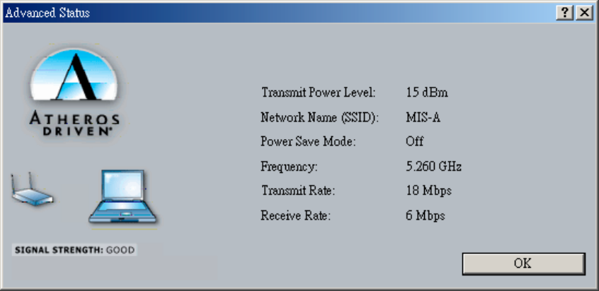
The Advanced button provides more detailed information regarding your wireless
connection.
•Transmit Power Level - Provides current setting of Radio output power
•Network Name (SSID) - The wireless network name (SSID) that the device is
currently connected with the network name.
•Power Save Mode - The type of Power Savings that is configured on the device
•Frequency - The current frequency that the Wireless device is connected or
scanning on.
•Transmit Rate - The transmit rate (Mbps) for the current connection for the wireless
driver.
•Receive Rate -The receive rate (Mbps) for the current connection for the driver.
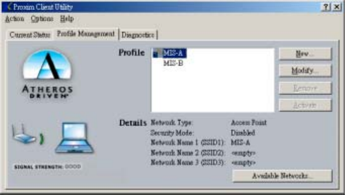
4 – 2 Profile Management
The Profile Management tab allows the user to configure several different user defined
profiles. Each profile can be configured to match the appropriate settings of a unique
wireless network.
The Profile box lists all the configured profiles. The Details dialog describes the basic
settings (SSID, Network Type, Security Mode) of the highlighted profile. The active
profile will be displayed with the wireless icon next to it. To make a profile active,
highlight the profile and click on the Activate button. By setting a Profile active, you
configure the wireless card to search for wireless networks that match up to those specific
profile wireless settings.
The Profile Management tab allows the user to configure several different user defined
profiles. Each profile can be configured to match the appropriate settings of a unique
wireless network.
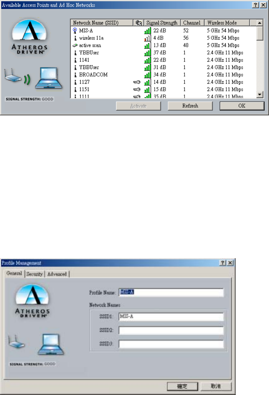
The Available networks button allows the user to view a list of all available wireless
network that are within range of the 802.11 a/b/g Mini-PCI. Each wireless network entry
displays the SSID, encryption settings, signal strength level, channel and wireless mode
information. You can create a new profile utilizing Available networks button by
highlighting the wireless network you want to create a profile for and clicking on the
Activate button.
4–3 Create or Modify a Profile
1. From the Profile Management tab Click on the New or Modify button
2. The Network Configuration Settings dialog box will appear
3. In the Profile Name box, type in a unique name that describes the wireless network
you are configuring the settings to connect to.
4. In the SSID boxes type in the SSID that matches up with the wireless network you
are trying to configuring the profile to connect with. There are three SSID
selections (SSID1, SSID2, SSID3) available; this feature allows you to configure a
single profile to match up to 3 different SSID’s.
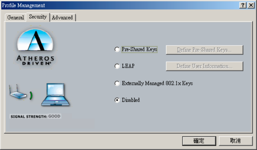
5. Select the Security Tab to manage the security settings associated with this profile
Select the appropriate security mode:
zPre-Shared Keys - This mode is commonly referred to as WEP encryption, and
allows for setting of all four WEP keys. The pre-shared key selection also allows
for setting of a unique key, which is used with higher forms of encryption such as
AES.
zLEAP - This is CCX compliant feature that allows for authentication with Cisco
access points. This mode should only be used if your Wireless LAN requires
LEAP authentication
zExternally Managed 802.1X Keys - This security mode allows for dynamic
switching
zof encryption keys using 802.1X authentication. This mode should only be used
if your
zWireless LAN requires 802.1X authentication.
zDisabled - Use this mode when there is no security authentication or encryption
is currently enabled on your Wireless LAN network.
6. Choose the security setting that is required on the wireless network. Once the
appropriate security mode is chosen the button next to the selection will enable you
to include any additional information required by that security mode.
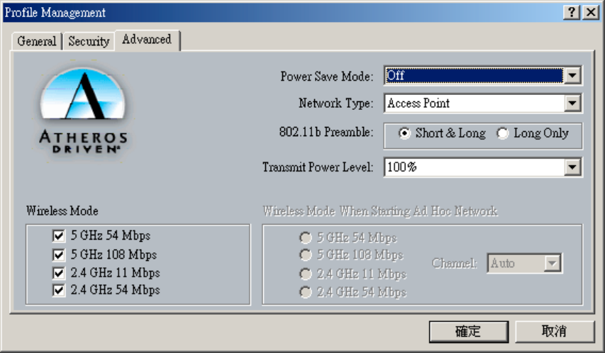
The advanced tab provide more complex wireless settings and these settings should
only be modified if there is a specific requirement on your wireless network.
zPower Save Mode - allows the user to minimize power utilized by the
802.11a/b/g Combo Card device. Note: Setting Power Save Mode to enabled
(Normal or Maximum) may cause the user to experience an extended
connection delay of up to one minute.
zNetwork Type - allows the user to configure the 802.11a/b/g Combo Card
device as either an Ad-hoc or Access Point type network
z802.11b Preamble - allows setting the preamble support to match up with the
specified wireless network.
zTransmit Power Level - allows the user to modify the power output of the
radio. Note: Setting this to any other value except 100% will decrease range
of your 802.11a/b/g Combo Card device.
zWireless Mode Setting - The wireless Mode settings allow the user to specify
which wireless frequency and data rate the wireless network is operating at. If
all selections are chosen, the 802.11a/b/g Combo Card device will
automatically search all frequencies and data rates for wireless networks that
match up to the profile settings.
zWireless Mode when starting Ad-Hoc setting - The "Wireless Mode when
starting ad-hoc setting" allows the user to determine the type of ad-hoc
network to be started. Note: This setting will only take effect if there are no
other ad-hoc networks with the same SSID currently operating within range.
If existing ad-hoc networks with the same SSID are currently operating, then
the 802.11a/b/g Combo Card device will connect using the frequency and data
rate provided by the exiting ad-hoc network.
4-4 Diagnostic Tab
The diagnostic TAB displays the current data statistics for both receive and transmit.
Additional statistics and driver information can be displayed using the appropriate labeled
buttons.
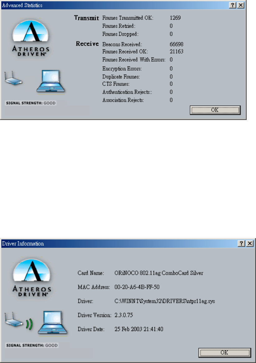
Advanced Statistics
The Advanced Statistics Information Tab contains more statistics information about the
network interface card. Access the Advanced Statistics Information from the Diagnostics
tab.
Driver Information
The Driver Information Tab contains general information about the network interface card
(the wireless network adapter) and the network driver interface specification (NDIS) driver.
Access the Driver Information from the Diagnostics tab.
The Driver Information tab displays the following information about your wireless Card.
zCard Name: The name of the wireless network adapter.
zMAC Address: The MAC address of the wireless network adapter.
zDriver: The driver name and path of the wireless network adapter driver.
zDriver Version: The version of the wireless network adapter driver.
zDriver Date: The creation date of the wireless network adapter driver.
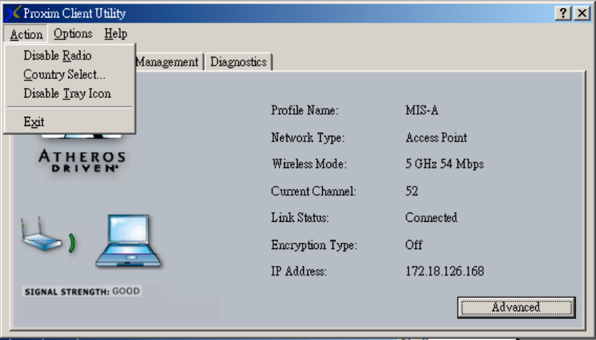
4-5 Action Menu
The Action menu allows for enabling and disabling both the wireless radio and/or system tray
icon.
Enable/Disable Radio
There may be situations when the user wants to disable the 802.11a/g Mini-PCIs radio, so that
the card cannot send or receive any wireless traffic. If a user is in an environment where there
are no wireless networks, the user may turn off the radio in order to minimize power
consumption of the 802.11a/b/g Mini-PCI.
In the ACTION menu of the ACU there is an Enable Radio/Disable Radio selection. The choice
provided in the menu will toggle the current state of the radio.
•
Enable Radio: The Radio is currently OFF (Disabled), and the “Enable Radio”
selection will turn ON the Radio of the wireless device.
•
Disable Radio: The Radio is currently ON (Enabled), and the “Disable Radio”
selection will turn OFF the Radio of the wireless device
The 802.11a/b/g Mini-PCI radio also may be disabled through an external button located on your
platform, please review your platform users guide for additional information about the wireless
enable/disable button
Country Select
Select the appropriate country code from the list provided to correspond with your
network settings.
Enable/Disable Tray Icon
In the ACTION menu of the ACU there is an Enable Tray Icon/Disable tray Icon selection. The
choice provided in the menu will toggle the current state of the System Tray Icon.
•
Enable Tray Icon: The Tray Icon is currently OFF (Disabled), and the “Enable Tray
Icon” selection will turn ON the ACU system Tray Icon.
•
Disable Tray Icon: The Tray Icon is currently ON (Enabled), and the “Disable Tray
Icon” selection will turn OFF the ACU system Tray Icon
Chapter 5 Wireless Configuration using Windows XP
5-1 Configuring Your Wireless Networking Settings
The Windows XP operating system has a built-in feature known as “Wireless Zero Config”
which has the capability to configure and control this Wireless LAN device. To configure
your device with this feature follow the steps below…
1. From the Start menu, select Control Panel.
2. Click Network and Internet Connections.
3. Click Network Connections.
4. Right-click the network connection associated with your W400-W500 Mini-PCI device, and
select Properties.
5. Click on the Wireless Networks tab.
6. Click on the link Setting Up Wireless Network Configuration.
When the Help and Support Center window appears, you can access information regarding wireless
Network configuration. To access configuration information of your adapter, follow the on-screen
instructions.
5-2 Advanced Wireless Settings
The 802.11a/b/g Mini-PCI has several advanced settings which may need to be
configured depending on your wireless network. It is recommended that these settings
remain unchanged unless there is a specific need that requires modifying these settings.
1. From the Start menu, select Control Panel.
2. Click Network and Internet Connections.
3. Click Network Connections.
4. Right-click the connection for your Compaq 802.11g Mini-PCI device, and select Properties.
4. From the General tab, click the Configure button.
5. Click on the Advanced TAB
6. Modify the wireless settings as required
5-3 Disabling the Radio
There may be situations when the user wants to disable the 802.11a/b/g Mini-PCIs radio, so
that the card cannot send or receive any wireless traffic. If a user is in an environment where
there are no wireless networks, the user may turn off the radio in order to minimize power
consumption of the 802.11a/b/g Mini-PCI. Follow the steps outlined in the Section 5-2 above
labeled “Advanced Wireless settings” and choose the Radio ON/OFF selction.
•Select OFF – To turn OFF radio of the W400-W500 Mini-PCI
•Select ON – To turn ON the radio of the W400-W500 Mini-PCI
The 802.11a/b/g Mini-PCI radio may also be disabled through an external button located on your
platform, please review your platform users guide for additional information about the wireless
enable/disable button
5-4 Help and Support Information
Configuration information and troubleshooting in Windows XP is available in
Microsoft’s Help and Support Center on Windows XP systems. Links to the appropriate Microsoft
Web sites are also available here.
To access this information:
1. From the Start menu, select Control Panel.
2. Click Network and Internet Connections.
3. Click Network Connections.
4. Right-click the connection for your W400-W500 Mini-PCI device, and select Properties.
5. From the General tab, click the Configure button.
6. From the General tab, click the Troubleshoot button.
When the Help and Support Center window appears, you can access information regarding the
Network adapter. To access configuration information of your adapter, follow the on-screen
Instructions. For the network adapter to function in a wireless LAN, you must change the settings at
Least once.
Appendix A - Glossary
ACU - Atheros Client Utility (ACU) is the utility that allows for configuration of the
W400-W500 Mini-PCI device
Access Point - An internetworking device that seamlessly connects wired and wireless networks
together.
Ad Hoc - A peer- to-peer wireless network without Access Point. A group of wireless clients
consistent an independent wireless LAN.
Backbone - The core infrastructure of a network, the portion of the network that transports
information from one central location to another central location. The information is then off-
loaded onto a local system.
BSS - Basic Service Set. An Access Point associated with several wireless stations.
ESS - Extended Service Set. More than one BSS can be configured as an Extended Service Set. An
ESS is basically a roaming domain.
ESSID –Extended Service Set Identifier. The length of the ESSID information is between 0 and 32
octets. A 0 length identifier indicates the broadcast SSID.
Ethernet - A popular local area data communications network, originally developed by Xerox
Corp., which accepts transmission from computers and terminals. Ethernet operates on 10/100
Mbps transmission rate over shielded coaxial cable or over shielded twisted pair telephone wire.
Infrastructure - An integrated wireless and wired LAN is called an infrastructure configuration.
Roaming - A function that allows one to travel with a mobile end system (wireless LAN mobile
station, for example) through the territory of a domain (an ESS, for example) while continuously
connecting to the infrastructure.
SSID – Service Set Identifier (SSID) is the network name used by the Wireless LAN . The length of
the SSID information is between 0 and 32 octets.
WEP –Wired Equivalent Privacy. The optional cryptographic confidentiality algorithm specified
by IEEE 802.11 used to provide data confidentiality that is subjectively equivalent to the
confidentiality of a wired local area network (LAN) medium that does not employ cryptographic
techniques to enhance privacy.

Appendix B - Security Tab (Profile Management)
The Security Tab allows you to configure the W400-W500 Mini-PCI device to match the
security settings of the Wireless LAN network.
Select the appropriate security mode…
•Pre-Shared Keys – This mode is commonly referred to as WEP encryption, and
allows for setting of all four WEP keys. The pre-shared key selection also allows for
setting of a unique key which is used with higher forms of encryption such as AES.
•LEAP – This is CCX compliant feature that allows for authentication with Cisco
access points. This mode should only be used if your Wireless LAN requires LEAP
authentication
•Externally Managed 802.1X Keys – This security mode allows for dynamic
switching of encryption keys using 802.1X authentication. This mode should only be
used if your Wireless LAN requires 802.1X authentication.
•Disabled – Use this mode when there is no security authentication or encryption is
currently enabled on your Wireless LAN network.
Pre-Shared Keys
Pre-Shared keys can be defined using the “Define Pre-Shared Keys” box
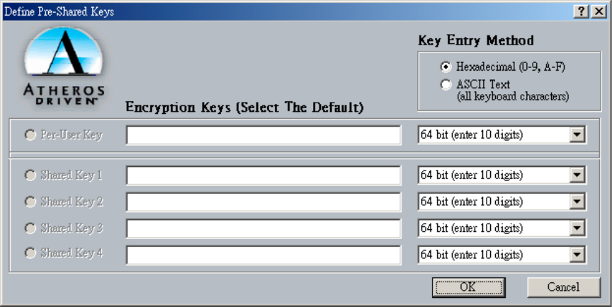
Key Entry Method - Determines the entry method for an encryption key:
zHexadecimal (0-9, A-F)
zASCII text (any keyboard characters, A-Z, 0-9).
PreUser Key - Defines the unique encryption key for network configuration security. The Pre
User key is used with many authentication mechanism and encryption
Shared Keys - Determines a set of shared encryption keys (First, Second, Third, Fourth) used
for wireless encryption and security. At least one Shared Key field must be populated to
enable security using a shared key. If more then one key is defined then Click on the radio
button to select a key as the default encryption key.
Key Length - The options for Key Length are
z64 bit encryption (10 digits)
z128 bit encryption (26 digits)
z152 bit encryption (32 digits)
The number of available characters allowed to be entered in the encryption key field will
automatically be determined by the Key length setting.
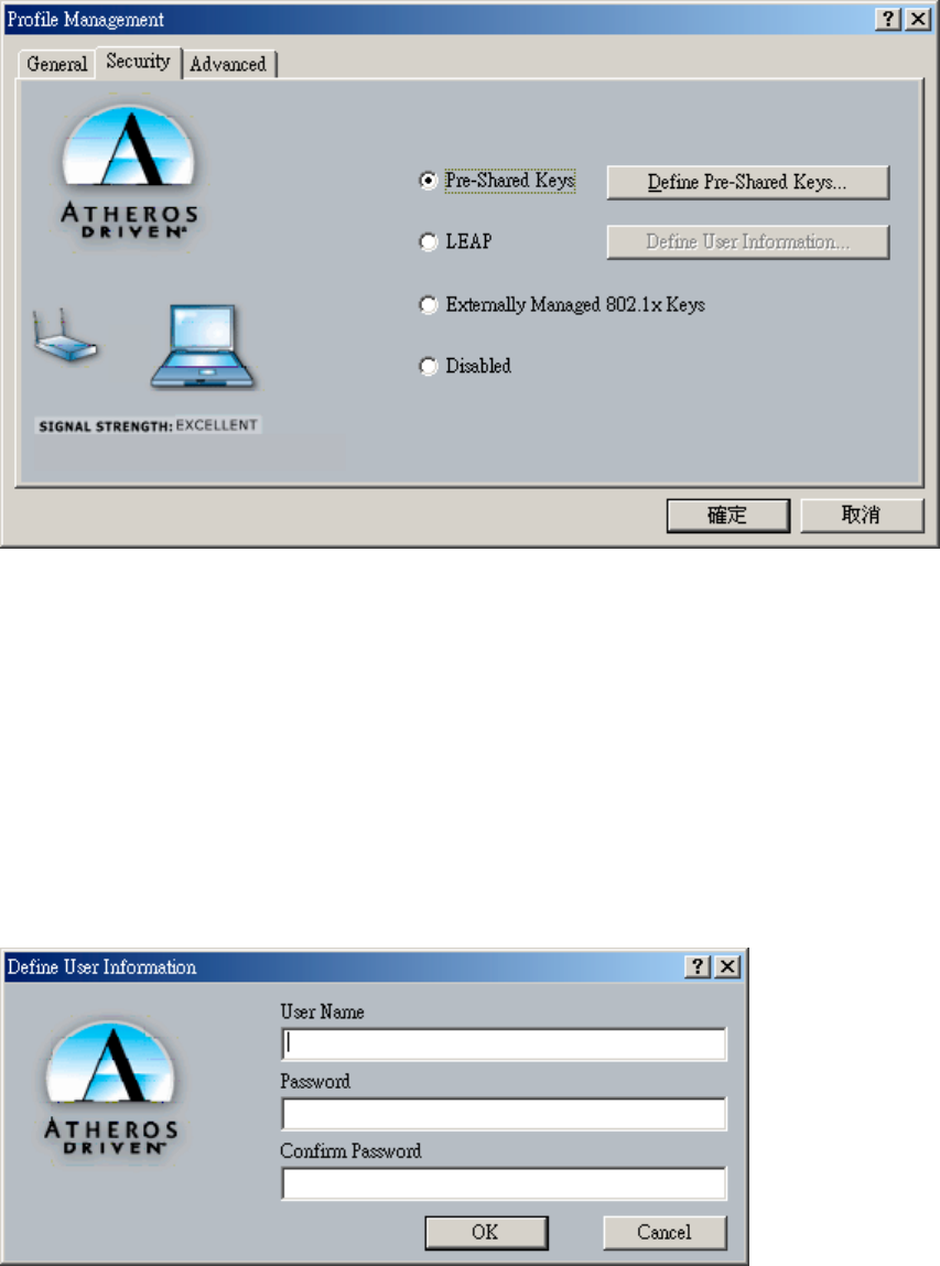
Setting LEAP authentication
LEAP authentication is a part of CCX compatibility and allows you to configure the Mini-PCI
device to match the work with a Wireless LAN that incorporates LEAP authentication. This
mode should only be used if your Wireless LAN requires LEAP authentication.
To configure the LEAP settings for a particular profile select LEAP in the security mode and
click on the Define LEAP settings button to configure the settings described below.
•Username - The username that is used to log in to the LEAP network
•Password – The password used to log in to the LEAP network. This password is
encrypted using the same encryption as the encryption keys.

Appendix C - Advanced TAB (Profile Management)
The advanced tab provide more complex wireless settings and these settings should only be
modified if there is a specific requirement on your wireless network.
a. Power Save Mode - allows the user to minimize power utilized by the
802.11a/b/g Mini-PCI Note: Setting Power Save Mode to enabled (Normal or
Maximum) may cause the user to experience an extended connection delay of up
to one minute.
b. Network Type - allows the user to configure the 802.11a/b/g Mini-PCI as either
a ad-hoc or infrastructure type network
c. 802.11b Preamble - allows setting the preamble support to match up with the
specified wireless network.
d. Transmit power Level - allows the user to modify the power output of the radio.
Setting. Note: Setting this to any other value except 100% will decrease range of
your 802.11a/b/g Mini-PCI.
Wireless Mode Setting
The wireless Mode settings allow the user to specify which wireless frequency and data rate the
wireless network is operating at. If all selections are chosen, the 802.11a/b/g Mini-PCI will
automatically search all frequencies and data rates for wireless networks that match up to the
profile settings.
Wireless Mode when starting Ad-Hoc setting
The “Wireless Mode when starting ad-hoc setting” allows the user to determine the type of
ad-hoc network to be started. Note: This setting will only take effect if there are no other ad-
hoc networks with the same SSID currently operating within range. If existing ad-hoc
networks with the same SSID are currently operating, then the 802.11a/b/g Mini-PCI will
connect using the frequency and data rate provided by the exiting ad-hoc network.

Federal Communication Commission Interference Statement
This equipment has been tested and found to comply with the limits for a Class B digital device,
pursuant to Part 15 of the FCC Rules. These limits are designed to provide reasonable
protection against harmful interference in a residential installation. This equipment generates,
uses and can radiate radio frequency energy and, if not installed and used in accordance with
the instructions, may cause harmful interference to radio communications. However, there is no
guarantee that interference will not occur in a particular installation. If this equipment does cause
harmful interference to radio or television reception, which can be determined by turning the
equipment off and on, the user is encouraged to try to correct the interference by one of the
following measures:
- Reorient or relocate the receiving antenna.
- Increase the separation between the equipment and receiver.
- Connect the equipment into an outlet on a circuit different from that to which the receiver is
connected.
- Consult the dealer or an experienced radio/TV technician for help.
FCC Caution: To assure continued compliance, any changes or modifications not expressly
approved by the party responsible for compliance could void the user's authority to operate this
equipment.
This device complies with Part 15 of the FCC Rules. Operation is subject to the following two
conditions: (1) This device may not cause harmful interference, and (2) this device must accept
any interference received, including interference that may cause undesired operation.
Statement Needed to be Shown on End Product
Since this module is installed inside the end product, the end product should be affixed a label on
visible area showing that this product contain a RF module, and also its FCC ID.
IMPORTANT NOTE:
FCC Radiation Exposure Statement:
This equipment complies with FCC radiation exposure limits set forth for an uncontrolled
environment. This equipment should be installed and operated with minimum distance 20cm
between the radiator & your body.
This transmitter must not be co-located or operating in conjunction with any other antenna or
transmitter.
The OEM integrator has to be aware not to provide information to the end user regarding how to
install or remove this RF module in the users manual of the end product which integrate this
module.
For operation within 5.15 ~ 5.25GHz frequency range, it is restricted to indoor environment, and the
a
ntenna of this device must be integral.

This device is intended only for OEM integrators under the following conditions:
1) The antenna must be installed such that 20 cm is maintained between the antenna and users, and
2) The transmitter module may not be co-located with any other transmitter or antenna.
As long as the 2 conditions above are met, further transmitter testing will not be required. However,
the OEM integrator is still responsible for testing their end-product for any additional compliance
requirements required with this module installed (for example, digital device emissions, PC peripheral
requirements, etc.).
IMPORTANT NOTE: In the event that these conditions can not be met (for example certain laptop
configurations or co-location with another transmitter), then the FCC authorization is no longer
considered valid and the FCC ID can not be used on the final product. In these circumstances, the
OEM integrator will be responsible for re-evaluating the end product (including the transmitter) and
Obtaining a separate FCC authorization.
End Product Labelling
This transmitter module is authorized only for use in devices where the antenna may be installed such
that 20 cm may be maintained between the antenna and users (for example access points, routers,
wireless ASDL modems, and similar equipment). The final end product must be labeled in a visible
area with the following: “ Contains TX FCC ID: HZB-C38WCW ”.
Manual Information That Must be Included
The users manual for end users must include the following information in a prominent location “
IMPORTANT NOTE: To comply with FCC RF exposure compliance requirements, the antenna used for
this transmitter must be installed to provide a separation distance of at least 20 cm from all persons and
must not be co-located or operating in conjunction with any other antenna or transmitter.”
I
f the end product integrating this module is going to be operated in 5.15 ~ 5.25GHz frequency range
,
t
he warning statement in the user manual of the end product should include the restriction of
o
perating this device in indoor could void the user's authority to operate the equipment.
Notice: "C38WCW" (802.11a/b/g MiniPCI Module) is limited for use in Alpha-1 access points. This
module can not be used in other system.
We will use driver to fix the domain code in EEPROM of the module and let channel is limilted from
CH1~CH11 when this product is imported to USA.
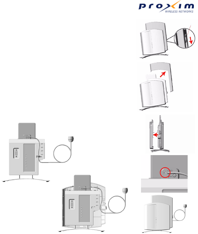
AP-600 Antenna Connector Cable
Note: For clarity, the power and Ethernet
cables are not shown.
1. Depress the tab to remove the cable cover.
2. Remove the cable cover.
3. Remove the front cover.
4. Attach the cable to the top connector of the AP-600.
5. Route the cable across front of the unit and secure it with
a tie-wrap (A) or route the cable inside the back cover (B)
as shown.
6. Replace the front cover and the cable cover.
© 2003 Proxim Corporation. All rights reserved. P/N 64902_? August 2003
5A
5B
1
2
3
4
6

Certified Solutions
WARNING: In order to use external antennas, your accesspoint must be equipped with an external antenna connector.
This antenna connection cable enables you to connect your ORiNOCO AP-600 access point to an external antenna. The
cable has on one side a an Proxim propietary connector, the other side has an industry-standard
N-connector/reverse N-connector. The user must use the correct type of antennas, cables and surge arrestor. Local radio
regulations or legislation may impose restrictions on the use of specific combinations. The user of this cable has to verify
that by using this cable, the legal requirements that are appropriate for the equipment and/or installation are complied with.
Examples of this are country specific type-approvals and/or maximum radiated output power. The antenna installer must
be a professional, aware of these regulations. At all times, it will be the responsibility of the end user to ensure that an
antenna installation complies with local radio regulations. For additional regulatory information, consult the regulatory flyer
delivered with your ORiNOCO access point. Proxim and its resellers or distributors are not liable for any damage or
violation of government regulations that may arise from the use of this cable.
FCC regulated countries
Note 1). Accepting countries: USA, Canada, Mexico, Brazil, Australia, Taiwan and unregulated countries.
Note 2). When using the 24dBi Parabolic Antenna, channels 1, 2, 10 and 11 cannot be used.
Note 3). For the products listed above, the 2.4GHz channels 13 and 14 are inaccessible.
Note 4). Radio models B11FNF, G11FNF and C38WCW are limited for use in AP-600 only.
Note 5). It is strictly prohibited to operate C38WCW outdoors in the frequency range of 5.15 to 5.25 GHz.
ETSI regulated countries
Note 1). Accepting countries: Europe (EU Counties including Norway and Switzerland), Singapore, Hong Kong.
Note 2). It is not allowed to connect any external antenna in: China. Proxim does not support this.
ORiNOCO access point antenna
connector cable surge arrester applicable antenna
extension cables Certified ORiNOCO
antennas
AP-600 11b (radio:B11FNF) applicable1,2,3) mandatory
for outdoor
applications
6 m (20ft) LMR-400
15m (50ft) LMR-400
22m (75ft) LMR-400
7dBi and 10dBi Omni
12dBi W-Angle / Window
14dBi Patch / Yagi
24dBi Parabolic Grid2)
AP-600 11g (radio G11FNF) not applicable - - not certified
AP-600 11abg
(radio:C38WCW) applicable1,3,4,5) not applicable not applicable dual band range extener
(model: AIN-WB-OD-B)
mandatory
for outdoor
applications
6 m (20ft) LMR-400
15m (50ft) LMR-400
22m (75ft) LMR-400
7dBi and 10dBi Omni
12dBi W-Angle / Window
14dBi Patch / Yagi
ORiNOCO access point antenna
connector cable surge arrester applicable antenna
extension cables Certified ORiNOCO
antennas
AP-600 11b (radio:B13ENE)
AP-600 11g (radio:G13ENE) applicable1) mandatory
for outdoor
applications
optional / any length 7dBi Omni
22m (75ft) LMR-400 10dBi Omni

Japan, South Korea
Note 1). It is not allowed to use channel 14 with directional antennas in: Japan
Note 2). It is not allowed to use the 7dBi and 10 dBi Omni antenna in: South Korea
Antenna table
ORiNOCO access point antenna
connector cable surge arrester applicable low-loss
antenna cables Certified ORiNOCO
antenna
Japan:
AP-600 11b (radio:B14GNJ)
AP-600 11g (radio:G13GNJ)
Korea:
AP-600 11b (radio: B13ENE)
AP-600 11g (radio: G11FNF)
applicable mandatory
for outdoor
applications
6 m (20ft) LMR-400 7dBi Omni2) (only for Japan)
22m (75ft) LMR-400 10dBi Omni2) (only forJapan)
optional / any length 12dBi W-angle1) / Window1)
optional / any length 14dBi Patch1) / Yagi1)
Antenna Product id Ordering Code Remarks
3dBi Omni IAN24-OD-3 not orderable Internal 2.4 GHz antenna for AP-600 11b
3dBi Omni IAN24-OD-3-S not orderable Internal 2.4 GHz antenna for AP-600 11b
provided with external RF connector
6dBi Omni IAN50-OD-6 not orderable Internal 5 GHz antenna for AP-600 11a
6dBi Omni IAN50-OD-6-S not orderable Internal 5 GHz antenna for AP-600 11a
provided with external RF connector
3dBi@2.4GHz;6dBi@5GHz IAN-WB-OD not orderable Internal 2.4 + 5 GHz dual band antenna
3dBi@2.4GHz;6dBi@5GHz IAN-WB-OD-S not orderable Internal 2.4 + 5 GHz dual band antenna
provided with external RF connector
Dual band range extender AIN-WB-OD External 2.4 + 5 GHz dual band antenna
5dBi Omni Directional AOU24-OD-55-B External 2.4 GHz antenna
7dBi Omni Directional AOU24-OD-77 External 2.4 GHz antenna
10dBi Omni Directional AOU24-OD-10 External 2.4 GHz antenna
12 dBi Wide Angle AOU24-WA-12-B External 2.4 GHz antenna
12 dBi Window AOU24-WI-12-B External 2.4 GHz antenna
14 dBi Patch AOU24-DI-14 External 2.4 GHz antenna
14 dBi Yagi AOU24-YA-1414 External 2.4 GHz antenna