Proxim Wireless L49U24U50 Wireless Access Point User Manual AP UG
Proxim Wireless Corporation Wireless Access Point AP UG
Contents
- 1. User manual
- 2. manual
User manual

226
AP-4000 Series User Guide
F
Regulatory Compliance/Professional Installation
NOTE: Please read this section before installing and using your product, and save these instructions.
Visit http://support.proxim.com for the latest regulatory compliance information.
This section contains important regulatory compliance and professional installation information for the following
products:
Product Model Numbers
ORiNOCO Tri-Mode Access Point AP-4000 AP-AG-AT-02
8670-AU
8670-AU2
8670-BR
8670-CN
8670-EU
8670-EU2
8670-HK
8670-JP
8670-JP2
8670-SG
8670-SK
8670-TW
8670-UK
8670-US
8670-US2
ORiNOCO Tri-Mode Access Point AP-4000M AP-AG-AT-02
8670M-AU
8670M-AU2
8670M-BR
8670M-CN
8670M-EU
8670M-EU2
8670M-HK
8670M-JP
8670M-JP2
8670M-SG
8670M-SK
8670M-TW
8670M-UK
8670M-US
8670M-US2
ORiNOCO Quad-Mode Access Point AP-4900M 8670M-PS-US

Regulatory Compliance/Professional Installation AP-4000 Series User Guide
227
Please see the following sections for more information:
•Safety Information (USA, Canada, & European Union)
•Federal Communications Commission (FCC) Compliance
•Professional Installation

Regulatory Compliance/Professional Installation AP-4000 Series User Guide
Safety Information (USA, Canada, & European Union)
228
Safety Information (USA, Canada, & European Union)
This product has been evaluated to, and complies with, the Safety requirements of UL60950:2000, and IEC60950:1999;
the Standards for the Safety of Information Technology Equipment. When using this device, basic safety precautions
should always be followed to reduce the risk of fire, electric shock and injury to persons, including the following:
• Operate and install this product as described in this manual. This device must be installed and used in strict
accordance with the manufacturer's instructions.
• This product is suitable for installation in air handling spaces (plenum).
• Use only the AC/DC power supply adapter provided. For replacement, contact your local supplier or distributor.
• To avoid the risk of electric shock from lightning, do not use this product during an electrical storm.
• Installation of this product must conform to local regulations and codes.
• When using this product with an external antenna, see the installation documentation provided with the antenna
system.
• No user serviceable parts; all repairs and service must be handled by a qualified service center.

Regulatory Compliance/Professional Installation AP-4000 Series User Guide
Federal Communications Commission (FCC) Compliance
229
Federal Communications Commission (FCC) Compliance
This device operates at 2.4 GHz, 5.15 - 5.35 GHz, and 5.75 - 5.85 in compliance with Part 15 of the FCC Rules. In
addition, the 8670M-PS-US model also operates at 4.9 GHz in compliance with Part 90 of the FCC Rules. Operation is
subject to the following two conditions: 1) this device may not cause harmful interference, and 2) this device must accept
any interference received, including interference that may cause undesired operation.
To comply with the FCC radio frequency exposure requirements, the following antenna installation and device operating
configurations must be satisfied:
• The 8670M-US2 model must be used indoors only and must be installed to provide a separation distance of at least
20 cm (8 inches) from all persons.
• Product models using external antennas require professional installation. The antennas used for professional
installation must be fixed-mounted on indoor/outdoor permanent structures with a separation distance of at least
100 cm from all persons.
• Antennas must not be co-located and must not operate in conjunction with any other antenna or transmitter.
See Professional Installation for antenna installation instructions, and Hardware Installation for cabling and mounting
instructions.
Modifications
Changes or modifications to this device that are not expressly approved by the manufacturer of the product could void the
user’s authority to operate the equipment.
Warnings
This equipment has been tested and found to comply with the limits for a Class B digital device, pursuant to Part 15 of the
FCC Rules. These limits are designed to provide reasonable protection again harmful interference in a residential
installation. This equipment generates, uses, and can radiate radio frequency energy, and, if not installed and used in
accordance with the instructions, may cause harmful interference to radio communications. However, there is no
guarantee that interference will not occur in a particular installation. If this equipment does cause harmful interference to
radio or television reception, which can be determined by turning the equipment off and on, the user is encouraged to try
and correct the interference by one or more of the following measures:
• Reorient or relocate the receiving antenna
• Increase the separation between the equipment and the receiver
• Connect the equipment to an outlet on a circuit different from that to which the receiver is connected
• Consult the dealer or an experienced radio/TV technician for help
Regulatory Compliance/Professional Installation AP-4000 Series User Guide
Professional Installation
230
Professional Installation
All products using external antennas must be professionally installed, and the transmit power of the system must be
adjusted by the professional installers to ensure that the system EIRP is in compliance with the limit specified by the
regulatory authority of the country of application.
See the following sections for more information:
•Installing External Antennas
•Adjusting Tx Output Power
•Antenna Types and Maximum Gain
NOTE: See Hardware Installation for cabling and mounting instructions.
Installing External Antennas
Only a professional installer can install external antennas on the AP-4000/4000M/4900M. For information on the AP’s
antenna functionality, see Antennas.
Follow the mounting instructions included with your external antenna, and then connect the antenna cable to the AP, as
follows:
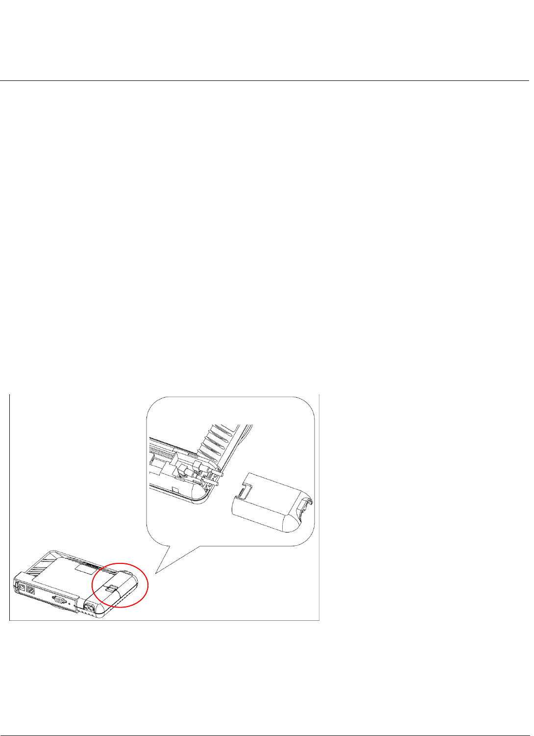
1. Press down near the center of the compartment covering and slide open the external antenna access compartments.
The compartment closer to the LED panel contains the connectors for the 802.11b/g radio, and the other compartment
contains the connectors for the 802.11a radio.
NOTE: AP-4000 models 8670-US2 and 8670-AU do not provide external antenna connectors for 5GHz (802.11a)
operation.
Figure F-1 Opening the Antenna Compartment
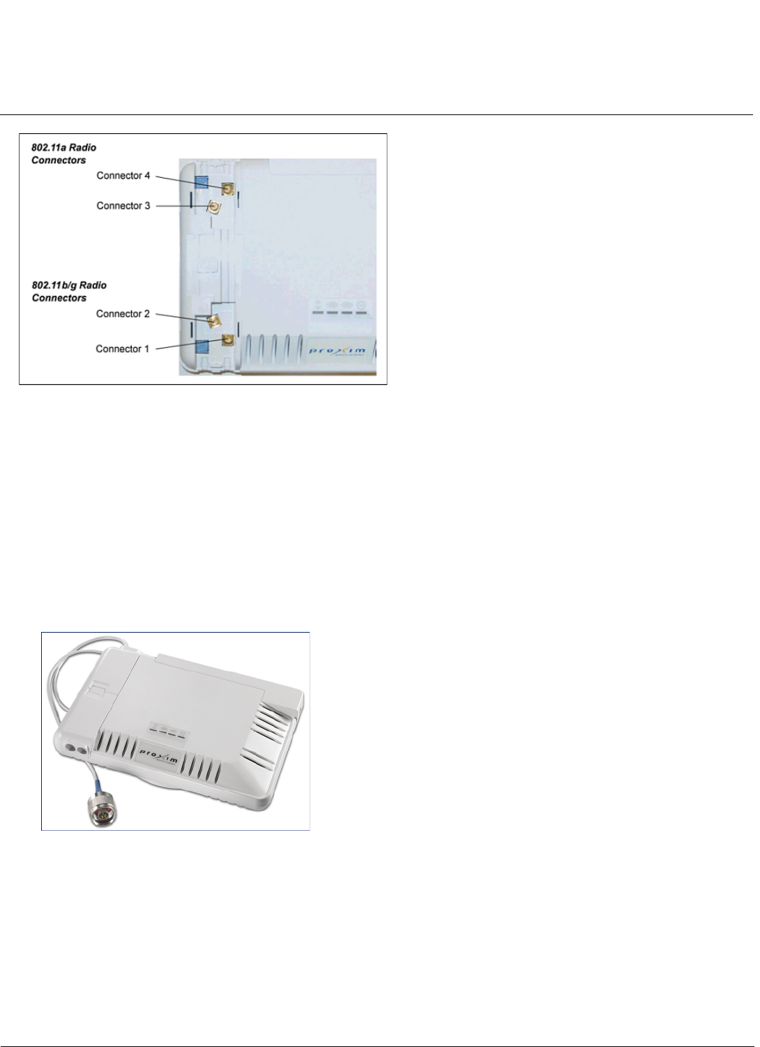
2. There are four antenna connectors in the AP-4000/4000M/4900M, labeled 1 through 4. Connectors 1 and 2 are for the
802.11b/g radio, and connectors 3 and 4 and for the 802.11a radio.Connect the antenna cable to connector 1 or 4 (the
connector closer to the LED panel in the compartment), depending on the radio.
NOTE: When the AP-4900M is configured to operate in the 4.9 GHz Public Safety operational mode, antenna
diversity is disabled, and antenna 3 is statically configured for use.
Regulatory Compliance/Professional Installation AP-4000 Series User Guide
Professional Installation
231
Figure F-2 AP-4000/4000M/4900M Antenna Connectors
3. If installing a second external antenna on a radio (not recommended), connect the antenna cable to connector 2
(802.11b/g radio) or connector 3 (802.11a radio).
4. Close the external antenna access compartments.
5. If desired, manually select which antenna(s) to use through the Command Line Interface. See Configure Antenna
Diversity.
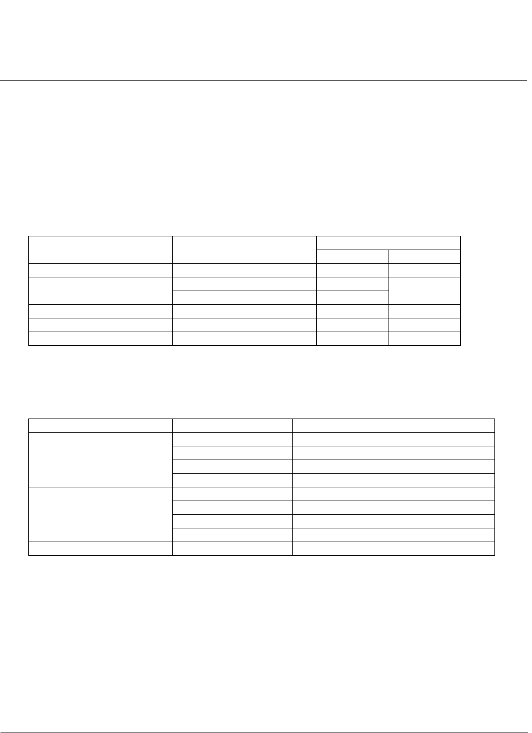
Attaching Antenna(s) to the AP-4900M for 4.9 GHz Operation
To attach an external antenna to the AP-4900M, attach the selected antenna to the pigtail attachment connected to the
AP’s antenna connector 3 (see Figure F-3).
For a list of recommended antennas, see http://www.proxim.com/products/wifi/accessories.
Figure F-3 AP-4900M External Antenna Connection
Regulatory Compliance/Professional Installation AP-4000 Series User Guide
Professional Installation
232
Adjusting Tx Output Power
Use the following formula in combination with the table of EIRP limits in US and EU countries to calculate system transmit
power (based on ERIP limits) of these countries:
Tx Power (dBm) = EIRP Limit (dBm) + FL (dB) – G (dB)
where:
Tx Power = Output power measured at the antenna input
EIRP Limit = EIRP limits specified below
FL = Feeder loss including loss of connectors
G = Antenna Gain
Antenna Types and Maximum Gain
For devices using external antennas, professional installers should select only the antenna types listed in the following
table, with gain not exceeding the listed maximum gain for each type.
Frequency (GHz) Bandwidth (MHz) EIRP Limit (dBm)
USA EU
2.4 - 2.4835 — 36 20
4.9 10 26 NA
20 29
5.15 - 5.25 — 23 23
5.25 - 5.35 — 30 20
5.725 - 5.850 — 36 14
Frequency Band Antenna Type Maximum Gain
2.4 GHz Omni 10
Panel 14
Yagi 14
Parabolic 24
5 GHz Omni 13
Panel 28.2
Sector 17
Parabolic 33.4
4.9 GHZ No restriction No restriction beyond EIRP compliance.