Proxim Wireless MP163650 Wireless Networking Device User Manual MP16 BOOK
Proxim Wireless Corporation Wireless Networking Device MP16 BOOK
Users Manual

Tsunami MP.16 3650 System
User Guide
Software Version 1.0.0

Tsunami MP.16 3650 System User Guide
2
Copyright
© 2008 Proxim Wireless Corporation. All rights reserved. Covered by one or more of the following U.S. patents: 5,231,634; 5,875,179;
6,006,090; 5,809,060; 6,075,812; 5,077,753. This user’s guide and the software described in it are copyrighted with all rights reserved. No part
of this publication may be reproduced, transmitted, transcribed, stored in a retrieval system, or translated into any language in any form by any
means without the written permission of Proxim Wireless Corporation.
Trademarks
Proxim is a registered trademark, and Tsunami and the Proxim logo are trademarks, of Proxim Wireless Corporation. All other trademarks
mentioned herein are the property of their respective owners.
Tsunami MP.16 3650 System User Guide
Software v. 1.0.0
P/N 76239, Feb 2009

Tsunami MP.16 3650 System User Guide
3
Contents
1 Introduction . . . . . . . . . . . . . . . . . . . . . . . . . . . . . . . . . . . . . . . . . . . . . . . . . . . . . . . . . . . . . . . . . . 8
Products Covered in this User Guide . . . . . . . . . . . . . . . . . . . . . . . . . . . . . . . . . . . . . . . . . . . . . . . . . . . . . . 8
Document Conventions . . . . . . . . . . . . . . . . . . . . . . . . . . . . . . . . . . . . . . . . . . . . . . . . . . . . . . . . . . . . . . . . . 9
Notes, Warnings, Cautions. . . . . . . . . . . . . . . . . . . . . . . . . . . . . . . . . . . . . . . . . . . . . . . . . . . . . . . . . . . . . . . . . . . . 9
Acronym List. . . . . . . . . . . . . . . . . . . . . . . . . . . . . . . . . . . . . . . . . . . . . . . . . . . . . . . . . . . . . . . . . . . . . . . . . . . . . . . 9
Product Features. . . . . . . . . . . . . . . . . . . . . . . . . . . . . . . . . . . . . . . . . . . . . . . . . . . . . . . . . . . . . . . . . . . . . 11
MP.16 System Overview . . . . . . . . . . . . . . . . . . . . . . . . . . . . . . . . . . . . . . . . . . . . . . . . . . . . . . . . . . . . . . . 13
System Setup . . . . . . . . . . . . . . . . . . . . . . . . . . . . . . . . . . . . . . . . . . . . . . . . . . . . . . . . . . . . . . . . . . . . . . . . . . . . . 13
Subscriber Station Initialization, Authentication, and Registration . . . . . . . . . . . . . . . . . . . . . . . . . . . . . . . . . . . . . 13
Wireless Communication and Service Classes . . . . . . . . . . . . . . . . . . . . . . . . . . . . . . . . . . . . . . . . . . . . . . . . . . . 14
System Monitoring . . . . . . . . . . . . . . . . . . . . . . . . . . . . . . . . . . . . . . . . . . . . . . . . . . . . . . . . . . . . . . . . . . . . . . . . . 14
MP.16 System Management Overview . . . . . . . . . . . . . . . . . . . . . . . . . . . . . . . . . . . . . . . . . . . . . . . . . . . . 15
Web Interface . . . . . . . . . . . . . . . . . . . . . . . . . . . . . . . . . . . . . . . . . . . . . . . . . . . . . . . . . . . . . . . . . . . . . . . . . . . . . 15
Command Line Interface . . . . . . . . . . . . . . . . . . . . . . . . . . . . . . . . . . . . . . . . . . . . . . . . . . . . . . . . . . . . . . . . . . . . 15
SNMP Management . . . . . . . . . . . . . . . . . . . . . . . . . . . . . . . . . . . . . . . . . . . . . . . . . . . . . . . . . . . . . . . . . . . . . . . . 15
2 Installation and Initialization . . . . . . . . . . . . . . . . . . . . . . . . . . . . . . . . . . . . . . . . . . . . . . . . . . . 17
Hardware Description . . . . . . . . . . . . . . . . . . . . . . . . . . . . . . . . . . . . . . . . . . . . . . . . . . . . . . . . . . . . . . . . . 18
Base Station Radio . . . . . . . . . . . . . . . . . . . . . . . . . . . . . . . . . . . . . . . . . . . . . . . . . . . . . . . . . . . . . . . . . . . . . . . . . 18
Subscriber Station Radio . . . . . . . . . . . . . . . . . . . . . . . . . . . . . . . . . . . . . . . . . . . . . . . . . . . . . . . . . . . . . . . . . . . . 19
Base Station/Subscriber Station LEDs . . . . . . . . . . . . . . . . . . . . . . . . . . . . . . . . . . . . . . . . . . . . . . . . . . . . . . . . . . 19
Power Adaptor . . . . . . . . . . . . . . . . . . . . . . . . . . . . . . . . . . . . . . . . . . . . . . . . . . . . . . . . . . . . . . . . . . . . . . . . . . . . 19
Antennas . . . . . . . . . . . . . . . . . . . . . . . . . . . . . . . . . . . . . . . . . . . . . . . . . . . . . . . . . . . . . . . . . . . . . . . . . . . . . . . . 20
Serial Connection . . . . . . . . . . . . . . . . . . . . . . . . . . . . . . . . . . . . . . . . . . . . . . . . . . . . . . . . . . . . . . . . . . . . . . . . . . 20
System Requirements . . . . . . . . . . . . . . . . . . . . . . . . . . . . . . . . . . . . . . . . . . . . . . . . . . . . . . . . . . . . . . . . . 22
Product Package . . . . . . . . . . . . . . . . . . . . . . . . . . . . . . . . . . . . . . . . . . . . . . . . . . . . . . . . . . . . . . . . . . . . . 23
Hardware Installation. . . . . . . . . . . . . . . . . . . . . . . . . . . . . . . . . . . . . . . . . . . . . . . . . . . . . . . . . . . . . . . . . . 25
Step 1: Choose a Location . . . . . . . . . . . . . . . . . . . . . . . . . . . . . . . . . . . . . . . . . . . . . . . . . . . . . . . . . . . . . . . . . . . 27
Step 2: Unpack Shipping Box . . . . . . . . . . . . . . . . . . . . . . . . . . . . . . . . . . . . . . . . . . . . . . . . . . . . . . . . . . . . . . . . . 27
Step 3: Assemble the Cable . . . . . . . . . . . . . . . . . . . . . . . . . . . . . . . . . . . . . . . . . . . . . . . . . . . . . . . . . . . . . . . . . . 28
Step 4: Determine Proper Mounting Orientation. . . . . . . . . . . . . . . . . . . . . . . . . . . . . . . . . . . . . . . . . . . . . . . . . . . 29
Step 5: Assemble Mounting Hardware . . . . . . . . . . . . . . . . . . . . . . . . . . . . . . . . . . . . . . . . . . . . . . . . . . . . . . . . . . 30
Step 6: Mount the Unit . . . . . . . . . . . . . . . . . . . . . . . . . . . . . . . . . . . . . . . . . . . . . . . . . . . . . . . . . . . . . . . . . . . . . . 31
Step 7: Plug in the Cables . . . . . . . . . . . . . . . . . . . . . . . . . . . . . . . . . . . . . . . . . . . . . . . . . . . . . . . . . . . . . . . . . . . 32
Step 8: Power on the Unit. . . . . . . . . . . . . . . . . . . . . . . . . . . . . . . . . . . . . . . . . . . . . . . . . . . . . . . . . . . . . . . . . . . . 33
Step 9: View LEDs . . . . . . . . . . . . . . . . . . . . . . . . . . . . . . . . . . . . . . . . . . . . . . . . . . . . . . . . . . . . . . . . . . . . . . . . . 33
Step 10: Align the Antenna . . . . . . . . . . . . . . . . . . . . . . . . . . . . . . . . . . . . . . . . . . . . . . . . . . . . . . . . . . . . . . . . . . . 34
Step 11: Tighten the Cables . . . . . . . . . . . . . . . . . . . . . . . . . . . . . . . . . . . . . . . . . . . . . . . . . . . . . . . . . . . . . . . . . . 34
Step 12: Weatherproof the Connectors . . . . . . . . . . . . . . . . . . . . . . . . . . . . . . . . . . . . . . . . . . . . . . . . . . . . . . . . . 35
Step 13: Install Documentation and Software. . . . . . . . . . . . . . . . . . . . . . . . . . . . . . . . . . . . . . . . . . . . . . . . . . . . . 36

Tsunami MP.16 3650 System User Guide
4
Using the Web Interface . . . . . . . . . . . . . . . . . . . . . . . . . . . . . . . . . . . . . . . . . . . . . . . . . . . . . . . . . . . . . . . 37
Logging In . . . . . . . . . . . . . . . . . . . . . . . . . . . . . . . . . . . . . . . . . . . . . . . . . . . . . . . . . . . . . . . . . . . . . . . . . . . . . . . 37
Web Interface Navigation. . . . . . . . . . . . . . . . . . . . . . . . . . . . . . . . . . . . . . . . . . . . . . . . . . . . . . . . . . . . . . . . . . . . 38
Installing Latest Software . . . . . . . . . . . . . . . . . . . . . . . . . . . . . . . . . . . . . . . . . . . . . . . . . . . . . . . . . . . . . . 39
Download Software . . . . . . . . . . . . . . . . . . . . . . . . . . . . . . . . . . . . . . . . . . . . . . . . . . . . . . . . . . . . . . . . . . . . . . . . 39
Install Software from your TFTP Server using the Web Interface . . . . . . . . . . . . . . . . . . . . . . . . . . . . . . . . . . . . . 39
Install Software from your TFTP Server using the CLI. . . . . . . . . . . . . . . . . . . . . . . . . . . . . . . . . . . . . . . . . . . . . . 39
First Configuration. . . . . . . . . . . . . . . . . . . . . . . . . . . . . . . . . . . . . . . . . . . . . . . . . . . . . . . . . . . . . . . . . . . . 41
3 Base Station Configuration . . . . . . . . . . . . . . . . . . . . . . . . . . . . . . . . . . . . . . . . . . . . . . . . . . . . 42
Introduction . . . . . . . . . . . . . . . . . . . . . . . . . . . . . . . . . . . . . . . . . . . . . . . . . . . . . . . . . . . . . . . . . . . . . . . . . 42
System Configuration . . . . . . . . . . . . . . . . . . . . . . . . . . . . . . . . . . . . . . . . . . . . . . . . . . . . . . . . . . . . . . . . . 44
MAC Configuration . . . . . . . . . . . . . . . . . . . . . . . . . . . . . . . . . . . . . . . . . . . . . . . . . . . . . . . . . . . . . . . . . . . 45
Basic MAC Configuration . . . . . . . . . . . . . . . . . . . . . . . . . . . . . . . . . . . . . . . . . . . . . . . . . . . . . . . . . . . . . . . . . . . . 45
Advanced MAC Configuration . . . . . . . . . . . . . . . . . . . . . . . . . . . . . . . . . . . . . . . . . . . . . . . . . . . . . . . . . . . . . . . . 46
Radio Configuration . . . . . . . . . . . . . . . . . . . . . . . . . . . . . . . . . . . . . . . . . . . . . . . . . . . . . . . . . . . . . . . . . . 47
Radio Downlink Burst Profile Configuration . . . . . . . . . . . . . . . . . . . . . . . . . . . . . . . . . . . . . . . . . . . . . . . . 48
Radio Uplink Burst Profile Configuration. . . . . . . . . . . . . . . . . . . . . . . . . . . . . . . . . . . . . . . . . . . . . . . . . . . 49
Networking Configuration . . . . . . . . . . . . . . . . . . . . . . . . . . . . . . . . . . . . . . . . . . . . . . . . . . . . . . . . . . . . . . 50
Basic Networking . . . . . . . . . . . . . . . . . . . . . . . . . . . . . . . . . . . . . . . . . . . . . . . . . . . . . . . . . . . . . . . . . . . . . . . . . . 50
VLANs . . . . . . . . . . . . . . . . . . . . . . . . . . . . . . . . . . . . . . . . . . . . . . . . . . . . . . . . . . . . . . . . . . . . . . . . . . . . . . . . . . 51
Bridging . . . . . . . . . . . . . . . . . . . . . . . . . . . . . . . . . . . . . . . . . . . . . . . . . . . . . . . . . . . . . . . . . . . . . . . . . . . . . . . . . 55
RADIUS Servers . . . . . . . . . . . . . . . . . . . . . . . . . . . . . . . . . . . . . . . . . . . . . . . . . . . . . . . . . . . . . . . . . . . . . . . . . . 57
Syslog . . . . . . . . . . . . . . . . . . . . . . . . . . . . . . . . . . . . . . . . . . . . . . . . . . . . . . . . . . . . . . . . . . . . . . . . . . . . . . . . . . 58
Trap Hosts . . . . . . . . . . . . . . . . . . . . . . . . . . . . . . . . . . . . . . . . . . . . . . . . . . . . . . . . . . . . . . . . . . . . . . . . . . . . . . . 61
Static Routes . . . . . . . . . . . . . . . . . . . . . . . . . . . . . . . . . . . . . . . . . . . . . . . . . . . . . . . . . . . . . . . . . . . . . . . . . . . . . 63
Global Positioning System (GPS) . . . . . . . . . . . . . . . . . . . . . . . . . . . . . . . . . . . . . . . . . . . . . . . . . . . . . . . . 65
GPS Synchronization . . . . . . . . . . . . . . . . . . . . . . . . . . . . . . . . . . . . . . . . . . . . . . . . . . . . . . . . . . . . . . . . . . . . . . . 65
Cable Assembly for GPS Unit . . . . . . . . . . . . . . . . . . . . . . . . . . . . . . . . . . . . . . . . . . . . . . . . . . . . . . . . . . . . . . . . 68
Secondary Management. . . . . . . . . . . . . . . . . . . . . . . . . . . . . . . . . . . . . . . . . . . . . . . . . . . . . . . . . . . . . . . 70
TFTP Table. . . . . . . . . . . . . . . . . . . . . . . . . . . . . . . . . . . . . . . . . . . . . . . . . . . . . . . . . . . . . . . . . . . . . . . . . . . . . . . 70
DHCP Server . . . . . . . . . . . . . . . . . . . . . . . . . . . . . . . . . . . . . . . . . . . . . . . . . . . . . . . . . . . . . . . . . . . . . . . . . . . . . 72
Subscriber Station Authentication . . . . . . . . . . . . . . . . . . . . . . . . . . . . . . . . . . . . . . . . . . . . . . . . . . . . . . . . 73
Subscriber Station List . . . . . . . . . . . . . . . . . . . . . . . . . . . . . . . . . . . . . . . . . . . . . . . . . . . . . . . . . . . . . . . . 74
Subscriber Station List Configuration . . . . . . . . . . . . . . . . . . . . . . . . . . . . . . . . . . . . . . . . . . . . . . . . . . . . . . . . . . . 75
Service Class Creation . . . . . . . . . . . . . . . . . . . . . . . . . . . . . . . . . . . . . . . . . . . . . . . . . . . . . . . . . . . . . . . . 82
Introduction . . . . . . . . . . . . . . . . . . . . . . . . . . . . . . . . . . . . . . . . . . . . . . . . . . . . . . . . . . . . . . . . . . . . . . . . . . . . . . 82
Subscriber Station Classes: Overview . . . . . . . . . . . . . . . . . . . . . . . . . . . . . . . . . . . . . . . . . . . . . . . . . . . . . . . . . . 82
Service Class Creation. . . . . . . . . . . . . . . . . . . . . . . . . . . . . . . . . . . . . . . . . . . . . . . . . . . . . . . . . . . . . . . . . . . . . . 85
Logging Configuration. . . . . . . . . . . . . . . . . . . . . . . . . . . . . . . . . . . . . . . . . . . . . . . . . . . . . . . . . . . . . . . . . 99

Tsunami MP.16 3650 System User Guide
5
Management Interface Configuration . . . . . . . . . . . . . . . . . . . . . . . . . . . . . . . . . . . . . . . . . . . . . . . . . . . . 100
4 Subscriber Station Configuration . . . . . . . . . . . . . . . . . . . . . . . . . . . . . . . . . . . . . . . . . . . . . . 101
System Configuration . . . . . . . . . . . . . . . . . . . . . . . . . . . . . . . . . . . . . . . . . . . . . . . . . . . . . . . . . . . . . . . . 102
Radio Configuration . . . . . . . . . . . . . . . . . . . . . . . . . . . . . . . . . . . . . . . . . . . . . . . . . . . . . . . . . . . . . . . . . 103
Network Configuration. . . . . . . . . . . . . . . . . . . . . . . . . . . . . . . . . . . . . . . . . . . . . . . . . . . . . . . . . . . . . . . . 104
Syslog Configuration . . . . . . . . . . . . . . . . . . . . . . . . . . . . . . . . . . . . . . . . . . . . . . . . . . . . . . . . . . . . . . . . . 105
Logging Configuration. . . . . . . . . . . . . . . . . . . . . . . . . . . . . . . . . . . . . . . . . . . . . . . . . . . . . . . . . . . . . . . . 106
5 Commands on BS/SS. . . . . . . . . . . . . . . . . . . . . . . . . . . . . . . . . . . . . . . . . . . . . . . . . . . . . . . . 107
Update to BS/SS. . . . . . . . . . . . . . . . . . . . . . . . . . . . . . . . . . . . . . . . . . . . . . . . . . . . . . . . . . . . . . . . . . . . 108
Update via TFTP . . . . . . . . . . . . . . . . . . . . . . . . . . . . . . . . . . . . . . . . . . . . . . . . . . . . . . . . . . . . . . . . . . . . . . . . . 108
Save Config to Server (BS Only) . . . . . . . . . . . . . . . . . . . . . . . . . . . . . . . . . . . . . . . . . . . . . . . . . . . . . . . 109
Save via TFTP . . . . . . . . . . . . . . . . . . . . . . . . . . . . . . . . . . . . . . . . . . . . . . . . . . . . . . . . . . . . . . . . . . . . . . . . . . . 109
Reboot . . . . . . . . . . . . . . . . . . . . . . . . . . . . . . . . . . . . . . . . . . . . . . . . . . . . . . . . . . . . . . . . . . . . . . . . . . . 110
Reset. . . . . . . . . . . . . . . . . . . . . . . . . . . . . . . . . . . . . . . . . . . . . . . . . . . . . . . . . . . . . . . . . . . . . . . . . . . . . 111
Passwords. . . . . . . . . . . . . . . . . . . . . . . . . . . . . . . . . . . . . . . . . . . . . . . . . . . . . . . . . . . . . . . . . . . . . . . . . 112
6 Log Messages on the BS/SS . . . . . . . . . . . . . . . . . . . . . . . . . . . . . . . . . . . . . . . . . . . . . . . . . . 113
Logging Configuration. . . . . . . . . . . . . . . . . . . . . . . . . . . . . . . . . . . . . . . . . . . . . . . . . . . . . . . . . . . . . . . . 113
Log Messages. . . . . . . . . . . . . . . . . . . . . . . . . . . . . . . . . . . . . . . . . . . . . . . . . . . . . . . . . . . . . . . . . . . . . . 115
Common Log Messages . . . . . . . . . . . . . . . . . . . . . . . . . . . . . . . . . . . . . . . . . . . . . . . . . . . . . . . . . . . . . . . . . . . .115
Base Station Log Messages. . . . . . . . . . . . . . . . . . . . . . . . . . . . . . . . . . . . . . . . . . . . . . . . . . . . . . . . . . . . . . . . . .115
Subscriber Station Log Messages . . . . . . . . . . . . . . . . . . . . . . . . . . . . . . . . . . . . . . . . . . . . . . . . . . . . . . . . . . . . .115
7 Monitoring the BS and SS . . . . . . . . . . . . . . . . . . . . . . . . . . . . . . . . . . . . . . . . . . . . . . . . . . . . 116
Base Station Monitoring . . . . . . . . . . . . . . . . . . . . . . . . . . . . . . . . . . . . . . . . . . . . . . . . . . . . . . . . . . . . . . 117
BS Ethernet Statistics. . . . . . . . . . . . . . . . . . . . . . . . . . . . . . . . . . . . . . . . . . . . . . . . . . . . . . . . . . . . . . . . . . . . . . .117
BS MAC Statistics . . . . . . . . . . . . . . . . . . . . . . . . . . . . . . . . . . . . . . . . . . . . . . . . . . . . . . . . . . . . . . . . . . . . . . . . .117
Service Flow Statistics . . . . . . . . . . . . . . . . . . . . . . . . . . . . . . . . . . . . . . . . . . . . . . . . . . . . . . . . . . . . . . . . . . . . . .118
Registered SS Statistics. . . . . . . . . . . . . . . . . . . . . . . . . . . . . . . . . . . . . . . . . . . . . . . . . . . . . . . . . . . . . . . . . . . . .119
System Inventory . . . . . . . . . . . . . . . . . . . . . . . . . . . . . . . . . . . . . . . . . . . . . . . . . . . . . . . . . . . . . . . . . . . . . . . . . 120
GPS Status. . . . . . . . . . . . . . . . . . . . . . . . . . . . . . . . . . . . . . . . . . . . . . . . . . . . . . . . . . . . . . . . . . . . . . . . . . . . . . 120
Subscriber Station Monitoring . . . . . . . . . . . . . . . . . . . . . . . . . . . . . . . . . . . . . . . . . . . . . . . . . . . . . . . . . . 121
SS Ethernet Statistics. . . . . . . . . . . . . . . . . . . . . . . . . . . . . . . . . . . . . . . . . . . . . . . . . . . . . . . . . . . . . . . . . . . . . . 121
SS MAC Statistics . . . . . . . . . . . . . . . . . . . . . . . . . . . . . . . . . . . . . . . . . . . . . . . . . . . . . . . . . . . . . . . . . . . . . . . . 121
SS Service Flow Statistics . . . . . . . . . . . . . . . . . . . . . . . . . . . . . . . . . . . . . . . . . . . . . . . . . . . . . . . . . . . . . . . . . . 122
A Command Line Interface . . . . . . . . . . . . . . . . . . . . . . . . . . . . . . . . . . . . . . . . . . . . . . . . . . . . . 123
CLI Overview. . . . . . . . . . . . . . . . . . . . . . . . . . . . . . . . . . . . . . . . . . . . . . . . . . . . . . . . . . . . . . . . . . . . . . . 124
Document Conventions . . . . . . . . . . . . . . . . . . . . . . . . . . . . . . . . . . . . . . . . . . . . . . . . . . . . . . . . . . . . . . . . . . . . 124
Basic Functionality . . . . . . . . . . . . . . . . . . . . . . . . . . . . . . . . . . . . . . . . . . . . . . . . . . . . . . . . . . . . . . . . . . . . . . . . 124

Tsunami MP.16 3650 System User Guide
6
CLI Rules . . . . . . . . . . . . . . . . . . . . . . . . . . . . . . . . . . . . . . . . . . . . . . . . . . . . . . . . . . . . . . . . . . . . . . . . . . . . . . . 125
Commands. . . . . . . . . . . . . . . . . . . . . . . . . . . . . . . . . . . . . . . . . . . . . . . . . . . . . . . . . . . . . . . . . . . . . . . . . . . . . . 126
Configuration from the Base Station . . . . . . . . . . . . . . . . . . . . . . . . . . . . . . . . . . . . . . . . . . . . . . . . . . . . . 132
System Parameters . . . . . . . . . . . . . . . . . . . . . . . . . . . . . . . . . . . . . . . . . . . . . . . . . . . . . . . . . . . . . . . . . . . . . . . 132
Base Station Parameters . . . . . . . . . . . . . . . . . . . . . . . . . . . . . . . . . . . . . . . . . . . . . . . . . . . . . . . . . . . . . . . . . . . 133
MAC Parameters . . . . . . . . . . . . . . . . . . . . . . . . . . . . . . . . . . . . . . . . . . . . . . . . . . . . . . . . . . . . . . . . . . . . . . . . . 136
Radio Parameters . . . . . . . . . . . . . . . . . . . . . . . . . . . . . . . . . . . . . . . . . . . . . . . . . . . . . . . . . . . . . . . . . . . . . . . . 136
VLAN ID List. . . . . . . . . . . . . . . . . . . . . . . . . . . . . . . . . . . . . . . . . . . . . . . . . . . . . . . . . . . . . . . . . . . . . . . . . . . . . 139
Subscriber Station List . . . . . . . . . . . . . . . . . . . . . . . . . . . . . . . . . . . . . . . . . . . . . . . . . . . . . . . . . . . . . . . . . . . . . 140
Service Class Creation. . . . . . . . . . . . . . . . . . . . . . . . . . . . . . . . . . . . . . . . . . . . . . . . . . . . . . . . . . . . . . . . . . . . . 143
Logging Configuration . . . . . . . . . . . . . . . . . . . . . . . . . . . . . . . . . . . . . . . . . . . . . . . . . . . . . . . . . . . . . . . . . . . . . 153
Trap Host Parameters . . . . . . . . . . . . . . . . . . . . . . . . . . . . . . . . . . . . . . . . . . . . . . . . . . . . . . . . . . . . . . . . . . . . . 154
Management Interface Parameters . . . . . . . . . . . . . . . . . . . . . . . . . . . . . . . . . . . . . . . . . . . . . . . . . . . . . . . . . . . 154
Configuration from the Subscriber Station . . . . . . . . . . . . . . . . . . . . . . . . . . . . . . . . . . . . . . . . . . . . . . . . 156
Subscriber Station Device Configuration . . . . . . . . . . . . . . . . . . . . . . . . . . . . . . . . . . . . . . . . . . . . . . . . . . . . . . . 156
Radio Configuration . . . . . . . . . . . . . . . . . . . . . . . . . . . . . . . . . . . . . . . . . . . . . . . . . . . . . . . . . . . . . . . . . . . . . . . 156
Logging Configuration . . . . . . . . . . . . . . . . . . . . . . . . . . . . . . . . . . . . . . . . . . . . . . . . . . . . . . . . . . . . . . . . . . . . . 157
Monitoring the BS and SS. . . . . . . . . . . . . . . . . . . . . . . . . . . . . . . . . . . . . . . . . . . . . . . . . . . . . . . . . . . . . 159
Software Version . . . . . . . . . . . . . . . . . . . . . . . . . . . . . . . . . . . . . . . . . . . . . . . . . . . . . . . . . . . . . . . . . . . . . . . . . 159
Network Status (SS only) . . . . . . . . . . . . . . . . . . . . . . . . . . . . . . . . . . . . . . . . . . . . . . . . . . . . . . . . . . . . . . . . . . . 159
Log Messages . . . . . . . . . . . . . . . . . . . . . . . . . . . . . . . . . . . . . . . . . . . . . . . . . . . . . . . . . . . . . . . . . . . . . . . . . . . 159
Base Station Statistics . . . . . . . . . . . . . . . . . . . . . . . . . . . . . . . . . . . . . . . . . . . . . . . . . . . . . . . . . . . . . . . . . . . . . 161
Subscriber Station Statistics. . . . . . . . . . . . . . . . . . . . . . . . . . . . . . . . . . . . . . . . . . . . . . . . . . . . . . . . . . . . . . . . . 163
B Technical Specifications . . . . . . . . . . . . . . . . . . . . . . . . . . . . . . . . . . . . . . . . . . . . . . . . . . . . . 165
Part Numbers . . . . . . . . . . . . . . . . . . . . . . . . . . . . . . . . . . . . . . . . . . . . . . . . . . . . . . . . . . . . . . . . . . . . . . 165
Base Station . . . . . . . . . . . . . . . . . . . . . . . . . . . . . . . . . . . . . . . . . . . . . . . . . . . . . . . . . . . . . . . . . . . . . . . . . . . . . 165
Subscriber Station . . . . . . . . . . . . . . . . . . . . . . . . . . . . . . . . . . . . . . . . . . . . . . . . . . . . . . . . . . . . . . . . . . . . . . . . 165
Base Station Antennas. . . . . . . . . . . . . . . . . . . . . . . . . . . . . . . . . . . . . . . . . . . . . . . . . . . . . . . . . . . . . . . . . . . . . 165
Subscriber Station Antennas . . . . . . . . . . . . . . . . . . . . . . . . . . . . . . . . . . . . . . . . . . . . . . . . . . . . . . . . . . . . . . . . 165
Power Injector . . . . . . . . . . . . . . . . . . . . . . . . . . . . . . . . . . . . . . . . . . . . . . . . . . . . . . . . . . . . . . . . . . . . . . . . . . . 165
Accessories/Spare Kits . . . . . . . . . . . . . . . . . . . . . . . . . . . . . . . . . . . . . . . . . . . . . . . . . . . . . . . . . . . . . . . . . . . . 166
Product Specifications. . . . . . . . . . . . . . . . . . . . . . . . . . . . . . . . . . . . . . . . . . . . . . . . . . . . . . . . . . . . . . . . 167
Features . . . . . . . . . . . . . . . . . . . . . . . . . . . . . . . . . . . . . . . . . . . . . . . . . . . . . . . . . . . . . . . . . . . . . . . . . . . . . . . . 167
Radio Performance . . . . . . . . . . . . . . . . . . . . . . . . . . . . . . . . . . . . . . . . . . . . . . . . . . . . . . . . . . . . . . . . . . 168
Hardware Specifications . . . . . . . . . . . . . . . . . . . . . . . . . . . . . . . . . . . . . . . . . . . . . . . . . . . . . . . . . . . . . . 169
Environmental Specifications . . . . . . . . . . . . . . . . . . . . . . . . . . . . . . . . . . . . . . . . . . . . . . . . . . . . . . . . . . . . . . . . 169
Size and Weight Specifications . . . . . . . . . . . . . . . . . . . . . . . . . . . . . . . . . . . . . . . . . . . . . . . . . . . . . . . . . . . . . . 169
Integrated Antenna (SS only). . . . . . . . . . . . . . . . . . . . . . . . . . . . . . . . . . . . . . . . . . . . . . . . . . . . . . . . . . . . . . . . 169
Antenna Port . . . . . . . . . . . . . . . . . . . . . . . . . . . . . . . . . . . . . . . . . . . . . . . . . . . . . . . . . . . . . . . . . . . . . . . . . . . . 170
Data Communication Port . . . . . . . . . . . . . . . . . . . . . . . . . . . . . . . . . . . . . . . . . . . . . . . . . . . . . . . . . . . . . . . . . . 170
Serial Configuration Port . . . . . . . . . . . . . . . . . . . . . . . . . . . . . . . . . . . . . . . . . . . . . . . . . . . . . . . . . . . . . . . . . . . 170

Tsunami MP.16 3650 System User Guide
7
C Technical Services and Support . . . . . . . . . . . . . . . . . . . . . . . . . . . . . . . . . . . . . . . . . . . . . . . 171
Obtaining Technical Services and Support . . . . . . . . . . . . . . . . . . . . . . . . . . . . . . . . . . . . . . . . . . . . . . . . 171
Support Options . . . . . . . . . . . . . . . . . . . . . . . . . . . . . . . . . . . . . . . . . . . . . . . . . . . . . . . . . . . . . . . . . . . . 172
Proxim eService Web Site Support . . . . . . . . . . . . . . . . . . . . . . . . . . . . . . . . . . . . . . . . . . . . . . . . . . . . . . . . . . . 172
Telephone Support . . . . . . . . . . . . . . . . . . . . . . . . . . . . . . . . . . . . . . . . . . . . . . . . . . . . . . . . . . . . . . . . . . . . . . . . 172
ServPak Support . . . . . . . . . . . . . . . . . . . . . . . . . . . . . . . . . . . . . . . . . . . . . . . . . . . . . . . . . . . . . . . . . . . . . . . . . 172
D Statement of Warranty . . . . . . . . . . . . . . . . . . . . . . . . . . . . . . . . . . . . . . . . . . . . . . . . . . . . . . . 173
Warranty Coverage . . . . . . . . . . . . . . . . . . . . . . . . . . . . . . . . . . . . . . . . . . . . . . . . . . . . . . . . . . . . . . . . . . 173
Repair or Replacement . . . . . . . . . . . . . . . . . . . . . . . . . . . . . . . . . . . . . . . . . . . . . . . . . . . . . . . . . . . . . . . 173
Limitations of Warranty. . . . . . . . . . . . . . . . . . . . . . . . . . . . . . . . . . . . . . . . . . . . . . . . . . . . . . . . . . . . . . . . . . . . . 173
Support Procedures . . . . . . . . . . . . . . . . . . . . . . . . . . . . . . . . . . . . . . . . . . . . . . . . . . . . . . . . . . . . . . . . . . . . . . . 173
Other Information . . . . . . . . . . . . . . . . . . . . . . . . . . . . . . . . . . . . . . . . . . . . . . . . . . . . . . . . . . . . . . . . . . . 174
Search Knowledgebase . . . . . . . . . . . . . . . . . . . . . . . . . . . . . . . . . . . . . . . . . . . . . . . . . . . . . . . . . . . . . . . . . . . . 174
Ask a Question or Open an Issue . . . . . . . . . . . . . . . . . . . . . . . . . . . . . . . . . . . . . . . . . . . . . . . . . . . . . . . . . . . . 174
Other Adapter Cards . . . . . . . . . . . . . . . . . . . . . . . . . . . . . . . . . . . . . . . . . . . . . . . . . . . . . . . . . . . . . . . . . . . . . . 174

8
Tsunami MP.16 3650 System User Guide
1
Introduction
Tsunami MP.16 systems consist of one or more Subscriber Stations (SS) that communicate with a Base Station (BS) to
provide high-performance wireless network connections. There are no DSL, cable, or leased-line contracts to negotiate.
Easy installation and operation allow network planners to quickly deploy up to 26 Mbps capacity between locations,
making it the ideal solution for:
• Establishing high-speed connections between Internet Service Providers and their customers
• Organizations requiring high-capacity WAN connectivity between multiple buildings or campuses
• Organizations or service providers seeking network redundancy for mission-critical wired connections
See the following sections for more information:
•Products Covered in this User Guide
•Document Conventions
–Notes, Warnings, Cautions
–Acronym List
•Product Features
•MP.16 System Overview
–System Setup
–Subscriber Station Initialization, Authentication, and Registration
–Wireless Communication and Service Classes
–System Monitoring
•MP.16 System Management Overview
–Web Interface
–Command Line Interface
–SNMP Management
Products Covered in this User Guide
This guide details functionality of the Tsunami MP.16 3650 System, consisting of the following:
Product Description
Tsunami MP.16 3650 Base Station Tsunami MP.16 3650 Base Station with external type-N antenna connector
Tsunami MP.16 3650 Subscriber
Station
Tsunami MP.16 3650 Subscriber Station with external type-N antenna connector
Tsunami MP.16 3650i Subscriber
Station
Tsunami MP.16 3650 Subscriber Station with integrated antenna

Introduction Tsunami MP.16 3650 System User Guide
Document Conventions
9
Document Conventions
Notes, Warnings, Cautions
The following special notations are used:
NOTE: A note contains important information that helps you make better use of the AP or your computer.
CAUTION: A Caution indicates potential damage to hardware or loss of data.
WARNING: A Warning indicates imminent danger to hardware or loss of data.
Acronym List
This document contains the following acronyms:
Acronym Definition
AK Authorization Key
ARQ Automatic Retransmission Request
AWG American Wire Gauge
BE Best Effort
BPSK Bi-Phase Shift Keying
BS Base Station
CAT5 Category 5
CID Connection ID
CINR Carrier to Interference Noise Ratio
CIR CIR Committed Information Rate; equivalent to "Minimum Reserved Traffic Rate" defined in
IEEE 802.16-2004 specification
CLI Command Line Interface
CRC Cyclic Redundancy Check
DCD Downlink Channel Descriptor
DL Downlink
FEC Forward Error Correction
GPS Global Positioning System
GUI Graphical User Interface
HCS Header Check Sequence
HTTP Hyper Text Transfer Protocol
ICMP Internet Control Message Protocol
IEEE Institute of Electrical and Electronics Engineers
IP Internet Protocol
IP TOS Internet Protocol Type of Service
LOS Line of Sight
MAC Media Access Control
MIR MIR Maximum Information Rate; equivalent to "Maximum Sustained Traffic Rate" defined in
IEEE 802.16-2004 specification.

Introduction Tsunami MP.16 3650 System User Guide
Document Conventions
10
NLOS Non Line of Sight
nrtPS Non-Real-Time Polling Services
OFDM Orthogonal Frequency Division Modulation
PDU Protocol Data Unit
PIR Packet Identification Rule
PoE Power over Ethernet
PPPoE Point to Point Protocol over Ethernet
QAM Quadrature Amplitude Modulation
QoS Quality of Service
QPSK Quadrature Phase Shift Keying
RADIUS Remote Authentication Dial-In User Service
RSNR Received Signal to Noise Ratio
RSSI Receive Signal Strength Indicator
rtPS Real-Time Polling Services
Rx Receive
SDU Service Data Units
SF Service Flow
SF Class Service Flow Class
SFID Service Flow ID
SLA Service Level Agreement
SNR Signal to Noise Ratio
SS Subscriber Station
SS Class Subscriber Station Class
TDD Time Division Duplex
TEK Traffic Encryption Key
TFTP Trivial File Transfer Protocol.
Tx Transmit
UCD Uplink Channel Descriptor
UGS Unsolicited Grant Service
UL Uplink
VLAN Virtual Local Area Network
VoIP Voice over IP
WAN Wide Area Network
Acronym Definition

Introduction Tsunami MP.16 3650 System User Guide
Product Features
11
Product Features
• Based on 802.16-2004 standard
• WiMAX Forum certified
• Licensed 3.65 - 3.675 GHz bands for worldwide operation
• Support for both 3.5 MHz and 7 MHz channel bandwidths
• Time Division Duplex operation
• Modulation modes: BS operation in any combination of the following modulation parameters: BPSK-1/2, QPSK-1/2,
QPSK-3/4, 16QAM-1/2, 16QAM-3/4, 64QAM-2/3, and 64QAM-3/4
• Cyclic prefix: Tb/32, Tb/16, Tb/8, and Tb/4
• FEC: concatenated, Reed-Solomon Convolutional Coding (RS-CC) only
• Frame duration (BS/SS): 5, 10, and 20 ms
• Up to approximately 10 Mbps in 3.5 MHz bandwidth
• 20 km LOS range with standard antennas
• All outdoor units with integrated antenna for simple installation
• Bridge and VLAN networking modes
• Local and remote network management through SNMP, HTTP (Web), or Command Line Interface
• Maximum coverage with OFDM for NLOS coverage
• Fast and reliable installation of Subscriber Station equipment at the end user’s site to minimize the installation cost
• Extensive performance monitoring and fault diagnostics from the Base Station to minimize “truck rolls” to the
end-user’s premises
• Low latency for VoIP services, and QoS to manage VoIP connections
• Bandwidth management to multiple service level agreements (SLAs)
• Capability to operate co-located Base Stations in a multi-sectored deployment
• Centralized provisioning and management of Subscriber Stations through Base Station
• Support for VLAN tagging and filtering (IEEE 802.1q)
• Uplink/downlink boundary configuration (BS)
• Adaptive modulation
• Two access control levels with password (Admin/User)
• Creation and maintenance of Subscriber Station service profiles (BS)
• Up to 256 Service Flow Classes (BS)
• Up to 512 Packet Identification Rules (BS)
• Up to 64 Subscriber Station classes (BS)
• Subscriber Station configuration and service provisioning (BS)
• Scheduling (UGS and BE) (BS)
• Ethernet packet lengths from 64 to 1600 bytes
• PPPoE transparent mode
• Database for up to 512 configurable Subscriber Stations (BS)
• RADIUS authentication (BS)
• MIR, drop ingress packets in excess of "maximum sustained traffic rate" per connection
• CIR, schedule non-BE traffic to maintain to a "minimum reserved traffic rate" per connection
• Antenna alignment tool
• Performance monitoring via CLI and Web-GUI
• Configuration import/export utility

Introduction Tsunami MP.16 3650 System User Guide
Product Features
12
• Statistics
• Ethernet connection LED indicators
• GPS LED Indicator (BS)
• SS management via Ethernet
• Power-on self test
• Continuous built-in self test
• Over-the-air and Ethernet software image upgrades via Web and CLI
• Revert to default configuration
• Software reset

Introduction Tsunami MP.16 3650 System User Guide
MP.16 System Overview
13
MP.16 System Overview
In the MP.16 system, a Base Station (BS) communicates and exchanges traffic with one or more Subscriber Stations
(SS). System implementation is streamlined, requiring initial setup on the Base Station of Base-Station-specific,
system-wide, and select Subscriber Station parameters, but requiring only minimal configuration on individual Subscriber
Stations themselves. This centralized configuration procedure allows for more efficient deployment of MP.16 systems.
The processes involved in the MP.16 system setup and functionality are described in the following sections:
•System Setup
•Subscriber Station Initialization, Authentication, and Registration
•Wireless Communication and Service Classes
•System Monitoring
System Setup
The administrator configures local BS and system-level options by using one of the BS’s management interfaces (HTTP,
CLI, or SNMP). Configuration from the BS includes the following:
•System: Configure local BS information, such as the system name, location, up time, and the contact person’s email
and phone number.
•MAC: Configure basic and advanced MAC parameters, including frame duration; downlink percentage; frame
synchronization mode; DCD, UCD, and initial ranging intervals; and TEK lifetime.
•Radio: Select the BS’s operating channel and configure downlink/uplink burst profiles.
•Networking: Configure the BS’s Ethernet address/mask, transmission speed, static routes, and VLANs, and external
(RADIUS) servers.
•Subscriber Station Authentication: Set the Net Entry mode (authorization level for SSs entering the network), and
choose a default Subscriber Station Class that will be assigned to all SSs entering the network without a pre-assigned
class.
•Subscriber Station List: Add Subscriber Stations to the Base Station’s list of registered SSs, or view the list of
registered SSs. Assign SS Classes to individual Subscriber Stations; override SS Class parameters on a per-SS
basis.
•Service Class Creation: Create new Packet Identification Rules (PIRs), Service Flows (SFs), and Subscriber Station
Classes (SS Classes), or view and modify existing PIRs, SFs, and SS classes.
•Log: Set the parameters for the logging functions of the BS.
BS configuration parameters are discussed in their entirety in Base Station Configuration.
Subscriber Station Initialization, Authentication, and Registration
When a Subscriber Station is initialized, it uses the configured frequency channels to search for a Base Station. If it finds
one, it synchronizes with the BS to determine initial timing, frequency, and power settings.
Once these settings are established, the SS attempts to register with the network. To do so, the SS sends the BS an
Authentication Information message followed by an Authentication Request message. The BS verifies that the SS is
authorized to join the network and sends an authorization response containing an Authorization Key (AK) encrypted with
the SS’s public key. This AK is used to secure the transmission of traffic encryption keys (TEKs), which secure further
transmissions between the SS and BS. Periodically, the SS is required to reauthenticate and refresh its key information.
The SS then sends the BS information about the SS’s capabilities and operational parameters. The BS begins initiating
Service Flows (see Wireless Communication and Service Classes). Once a Service Flow is active, a connection is
established. The BS sets up uplink and downlink connections to carry traffic between the SS and BS.
Much of the SS’s configuration is set by the BS; that is, the administrator configures SS parameters on the BS, and the
BS provisions this configuration information to the SS when it registers with the BS. However, an administrator can

Introduction Tsunami MP.16 3650 System User Guide
MP.16 System Overview
14
configure Subscriber Station parameters locally on the SS by using one of the SS’s management interfaces (HTTP, CLI,
or SNMP). Configuration from the SS includes the following:
•SS: Configure local SS information, such as the system name, location, up time, and the contact person’s email and
phone number.
•Radio: Select the SS’s operating channel, channel bandwidth, and optionally configure a connection with a specific
BS.
•Networking: Configure the SS’s Ethernet address/mask and default gateway.
•Log: Set the parameters for the logging functions of the SS.
SS configuration parameters are discussed in their entirety in Subscriber Station Configuration.
Wireless Communication and Service Classes
Traffic is exchanged between the BS and SS through uplink connections (SS to BS) and downlink connections (BS to
SS). The MP.16 system supports Time Division Duplex (TDD) operation. In TDD operation, wireless transmissions are
divided into fixed-duration frames, with uplink and downlink subframes making up each frame.
In order to allow the administrator to efficiently define connections and their associated traffic types and QoS parameters,
the BS uses defined classes of service, called Subscriber Station Classes (SS Classes).
SS Classes, configured on the BS and provisioned to SSs in the network, determine how different types of traffic are
handled. As a packet is transmitted between the BS and SS, it is compared to a defined set of Packet Identification
Rules. Each rule contains classifiers against which the packet is matched; depending on which classifiers the packet
matches, it is directed to a particular uplink or downlink Service Flow. The Service Flow determines the QoS treatment for
each packet. Each SS Class contains at least one uplink and one downlink Service Flow (but as many as 16), each with
associated QoS settings. Up to 64 SS Classes can be created.
By using multiple SS Classes that include different SFs, a service provider can offer tiers of service to customers. A
“premium” plan, for instance, may consist of SS Classes offering SFs with improved QoS over a “standard” or “basic”
plan.
The MP.16 system comes supplied with pre-defined SS Classes, Service Flows, and PIRs. In addition, you can
customize the predefined SS Classes, Service Flows, and PIRs or create new ones that uniquely serve the needs of your
network environment.
Upon entering the network, an SS uses either the default SS class configured on the BS (under the Subscriber Station
Authentication tab) or a pre-assigned SS class (assigned by the BS under the Subscriber Station List tab or by a
configured RADIUS server).
See Service Class Creation for information on defining custom SS classes.
System Monitoring
Administrators and authorized users can monitor the following system statistics.
• Log messages
• Interface statistics
•MAC statistics
• Service Flow statistics
• SS Statistics (BS only)
See Log Messages on the BS/SS.

Introduction Tsunami MP.16 3650 System User Guide
MP.16 System Management Overview
15
MP.16 System Management Overview
The MP.16 system offers two levels of management access:
•Administrators can display or change configuration settings, and can display configuration settings, logs, and
statistics.
•Users can display configuration settings, logs, and statistics.
The following management interfaces are available:
•Web Interface
•Command Line Interface
•SNMP Management
Web Interface
The Web interface (HTTP) provides easy access to configuration settings and network statistics from any computer on
the network.
You can access the Web interface over your network, over the Internet, or with a crossover Ethernet cable connected
directly to your computer’s Ethernet port. See Using the Web Interface for instructions and the following chapters for
configuration and monitoring information:
•Base Station Configuration
•Subscriber Station Configuration
•Commands on BS/SS
•Log Messages on the BS/SS
•Monitoring the BS and SS
Command Line Interface
The Command Line Interface (CLI) is a text-based configuration utility that supports a set of keyboard commands and
parameters to configure and manage the MP.16 system. An administrator enters command statements, composed of CLI
commands and their associated parameters. Statements may be issued from the keyboard for real time control, or from
scripts that automate configuration.
The CLI can be accessed through a terminal emulator over a serial connection or via Telnet. See Command Line
Interface for more information on the CLI and for a list of CLI commands and parameters.
SNMP Management
In addition to the Web interface and the CLI, you also can manage and configure your unit using the Simple Network
Management Protocol (SNMP). Note that this requires an SNMP manager program (sometimes called MIB browser) or a
Network Manager program using SNMP, such as HP OpenView or Castle Rock’s SNMPc. The units support several
Management Information Base (MIB) files that describe the parameters that can be viewed and configured using SNMP:
• ProximTmp16.mib
• WMAN-IF-MIB.mib
MIB files are provided on the CD included with your unit. You must compile one or more of these MIB files into your
SNMP program’s database before you can manage your unit using SNMP.
These MIBs define the read and read/write objects you can view or configure using SNMP. These objects correspond to
most of the settings and statistics that are available with the other management interfaces. The MIB can be opened with
any text editor, such as Microsoft Word, Notepad, and WordPad.
NOTE: When you update the software in the unit, you must also update the MIBs to the same release. Because the
parameters in the MIB may have changed, you may not have full control over the features in the new release.

Introduction Tsunami MP.16 3650 System User Guide
MP.16 System Management Overview
16
See the documentation that came with your SNMP manager for instructions about how to compile MIBs.
IMPORTANT!
The remainder of the User Guide discusses installing your MP.16 system and managing it using the Web and
CLI interfaces.

17
Tsunami MP.16 3650 System User Guide
2
Installation and Initialization
•Hardware Description
–Base Station Radio
–Subscriber Station Radio
–Base Station/Subscriber Station LEDs
–Power Adaptor
–Antennas
–Serial Connection
•System Requirements
•Product Package
•Hardware Installation
–Step 1: Choose a Location
–Step 2: Unpack Shipping Box
–Step 3: Assemble the Cable
–Step 4: Determine Proper Mounting Orientation
–Step 5: Assemble Mounting Hardware
–Step 6: Mount the Unit
–Step 7: Plug in the Cables
–Step 8: Power on the Unit
–Step 9: View LEDs
–Step 10: Align the Antenna
–Step 11: Tighten the Cables
–Step 12: Weatherproof the Connectors
–Step 13: Install Documentation and Software
•Using the Web Interface
–Logging In
–Web Interface Navigation
•Installing Latest Software
•First Configuration

Installation and Initialization Tsunami MP.16 3650 System User Guide
Hardware Description
18
Hardware Description
The BS and SS equipment consists of a radio, power adaptor, and external antenna connectors (on some SS models).
See Product Package for a full list of included components.
The BS radio provides a wireless link between an Ethernet connection and SSs registered to the BS. It is installed
outdoors in close proximity to its antenna so that the RF cable connection to the antenna has minimal loss. The power
adaptor powers the BS over the PoE CAT5 cable. It also provides an Ethernet connection with the same PoE CAT5
cable, and the power adaptor’s second RJ45 connector connects the 100Base-T data signals to the backhaul network.
The BS comes with a Type-N connector to attach external antennas. A single omni-directional antenna or multiple sector
antennas (in combination with additional BSs) may be used to provide 360 degrees of coverage.
The SS radio provides a wireless non-line-of-site connection with the BS. A CAT5 cable connects the SS to the user’s
switch/router through the power adaptor to provide DC power to the radio and 100/10Base-T Ethernet service between
the radio and a switch/router. This data port can be connected to either a single Ethernet host or to an Ethernet switch so
that the SS can address multiple Ethernet hosts. The SS comes with an integrated panel antenna or a Type-N antenna
connector to enable the use of external antennas. External antennas may be used to provide greater range.
See the following:
•Base Station Radio
•Subscriber Station Radio
•Base Station/Subscriber Station LEDs
•Power Adaptor
•Antennas
•Serial Connection
Base Station Radio
The BS radio operates in one of 744 possible frequency channels set by the user in the licensed 3.65 - 3.675 GHz bands,
and time duplexes between transmitting downlink bursts to SSs and receiving uplink bursts from SSs.
The major functions of the BS radio include:
•Signal Radiation/Reception: An external antenna receives downlink and radiates uplink RF signals.
•Upconversion/Downconversion: Received RF signals are amplified and downconverted to baseband for
demodulation; modulated uplink signals from baseband to RF are upconverted and amplified to a controlled power
level.
•Modulation/Demodulation: Downlink MAC protocol data units (PDUs) are Forward Error Correction (FEC) encoded
and modulate the baseband downlink. Uplink bursts received from SSs are demodulated and FEC decoded into MAC
PDUs. The demodulation function also includes carrier-frequency, symbol-timing synchronization, and channel
equalization.
•Wireless MAC Functions: Control and traffic data from the Ethernet services are formatted into MAC PDUs and
assembled into downlink bursts. Uplink bursts received from SSs are parsed into MAC control messages and traffic
SDUs destined for the Ethernet service. The MAC also controls frame synchronization, SS network entry, SS ranging
and power control, bandwidth requests, QoS scheduling, encryption, and key management.
•Network Services: Services to connect a 10/100Base-T Ethernet interface to the wireless network include the
following capabilities: bridging, VLAN awareness, ICMP, and PPPoE.
•BS Management: Configuration and dynamic control of the BS are provided via a command line interface (CLI), an
HTTP GUI, and SNMP. Performance and status data can be displayed to enable a local or remote operator to
determine the operational status, usage, and link performance of the BS and its active SSs.
Installation and Initialization Tsunami MP.16 3650 System User Guide
Hardware Description
19
Subscriber Station Radio
The SS radio operates in one of 744 possible frequency channels set by the user in the licensed 3.65 - 3.675 GHz bands,
and time duplexes between receiving downlink bursts from the BS and transmitting uplink bursts to the BS.
The major functions of the SS radio include:
•Signal Radiation/Reception: An integrated or external antenna receives downlink and radiates uplink RF signals.
•Upconversion/Downconversion: Received downlink RF signals are amplified and downconverted to baseband for
demodulation; modulated uplink signals from baseband to RF are upconverted and amplified to a controlled power
level.
•Modulation/Demodulation: Received baseband signals are demodulated and FEC decoded into MAC protocol data
units (PDUs). Uplink PDUs are FEC encoded and modulate the baseband uplink. The demodulation function also
includes carrier-frequency, symbol-timing synchronization, and channel equalization.
•Wireless MAC Functions: Control and traffic messages destined for Ethernet hosts and TDM interfaces connected
to the SS are parsed from downlink MAC PDUs. Uplink PDUs are constructed to transport control and traffic data from
Ethernet hosts and TDM interfaces. The MAC also controls uplink synchronization, power control, network entry,
bandwidth requests, QoS scheduling, encryption, and key management.
•Network Services: Services to connect a 10/100Base-T Ethernet interface to the wireless network include the
following capabilities: bridging, VLAN awareness, ICMP, and PPPoE.
•SS Management: Configuration and dynamic control of the SS are provided via the BS, a command-line interface
(CLI), an HTTP GUI, and SNMP. Performance and status data can be displayed to enable a local or remote operator
to determine the operational status, usage, and link performance of the SS. Status and performance information is
also sent to the BS as requested.
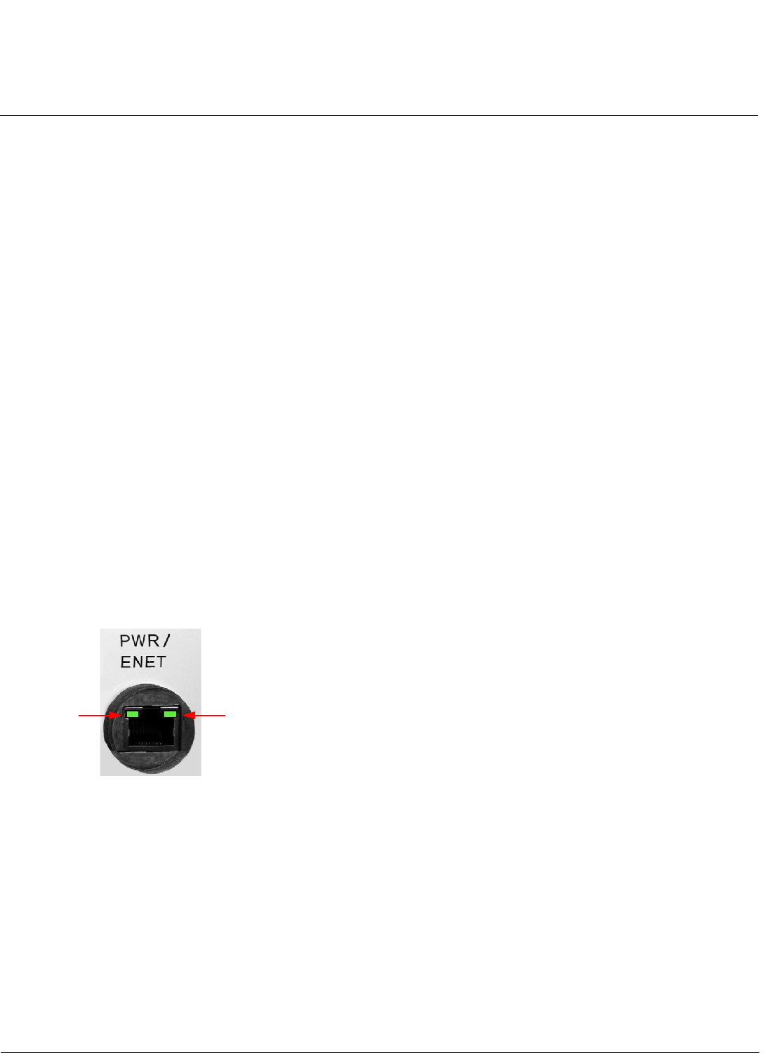
Base Station/Subscriber Station LEDs
Two LED indicators are available on the Ethernet port of the BS and SS. These LEDs display the activity of the Ethernet
and RF links. If a water-tight cap is installed with the unit, you will need to unscrew it to view the LEDs.
Figure 2-1 BS/SS LED Indicators
Power Adaptor
The power adaptor provides Power-over-Ethernet (PoE), supplying electricity and wired connectivity to the unit over a
single 24 AWG CAT5 (diameter .114 to .250 inches/2.9 to 6.4 mm). The unit is not 802.3af-compatible. Always use the
supplied power injector to ensure that the unit is powered properly. Note that the Active Ethernet module provides +48
VDC over a standard CAT5 Ethernet cable.
Depressing the power adaptor’s Reload button for five seconds during power-up remotely resets BS/SS parameters
affecting communication between the BS and SS to their factory default settings: IP address, subnet mask, user name,
password, Ethernet speed/duplex, and VLAN mode.
RF
LED
Ethernet
LED
Installation and Initialization Tsunami MP.16 3650 System User Guide
Hardware Description
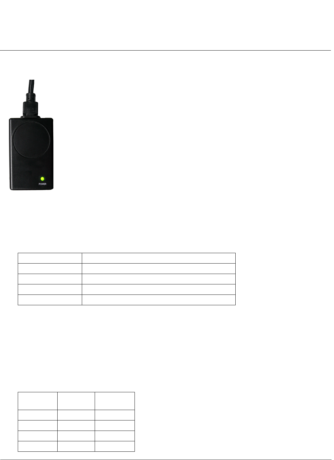
20
Power Adaptor LED
An LED is provided on top of the power adaptor, as shown in the following figure.
Figure 2-2 Power Adaptor LEDs
When the LED is green, the power is on.
Antennas
Some Tsunami MP.16 3650 units have integrated antennas, while others have external antenna connectors (Type-N) and
no integrated antennas. External connector specifications are as follows:
For more information on external antennas, see the Tsunami MP.16 3650 System Antenna Installation Guide and the
Tsunami MP.16 System Recommended Antennas guide.
Serial Connection
The serial connection is used for issuing CLI commands using a terminal emulator. The serial connection is made with an
RJ45 to DB9 connector (also referred to as a “dongle”). During Hardware Installation, plug the RJ45 end of the dongle
into the GPS/SYNC port of the radio and connect the serial end to your PC.
The serial dongle also includes an in-line stereo jack to aid in antenna alignment (upcoming feature).
Connections are as follows:
Characteristic Limit
Connector type Type-N, female
Impedance 50 Ohms over the operating frequency band
Antenna Return Loss -10 dB maximum
DC Resistance DC resistance to ground less than 1 Ohm
In-Line
Stereo Jack
DB9
Connector
RJ45
Plug
NC NC 1
NC 5 2
NC 5 3
NC 2 4

Installation and Initialization Tsunami MP.16 3650 System User Guide
Hardware Description
21
NC 3 5
156
2, 3 NC 6
NC NC 8
In-Line
Stereo Jack
DB9
Connector
RJ45
Plug

Installation and Initialization Tsunami MP.16 3650 System User Guide
System Requirements
22
System Requirements
• A 10Base-T Ethernet or 100Base-TX Fast Ethernet switch or hub or cross-over Ethernet cable
• A computer that is connected to the same IP network and has one of the following Web browsers installed:
– Microsoft® Internet Explorer 6
– Mozilla Firefox® 1.5
Installation and Initialization Tsunami MP.16 3650 System User Guide
Product Package
23
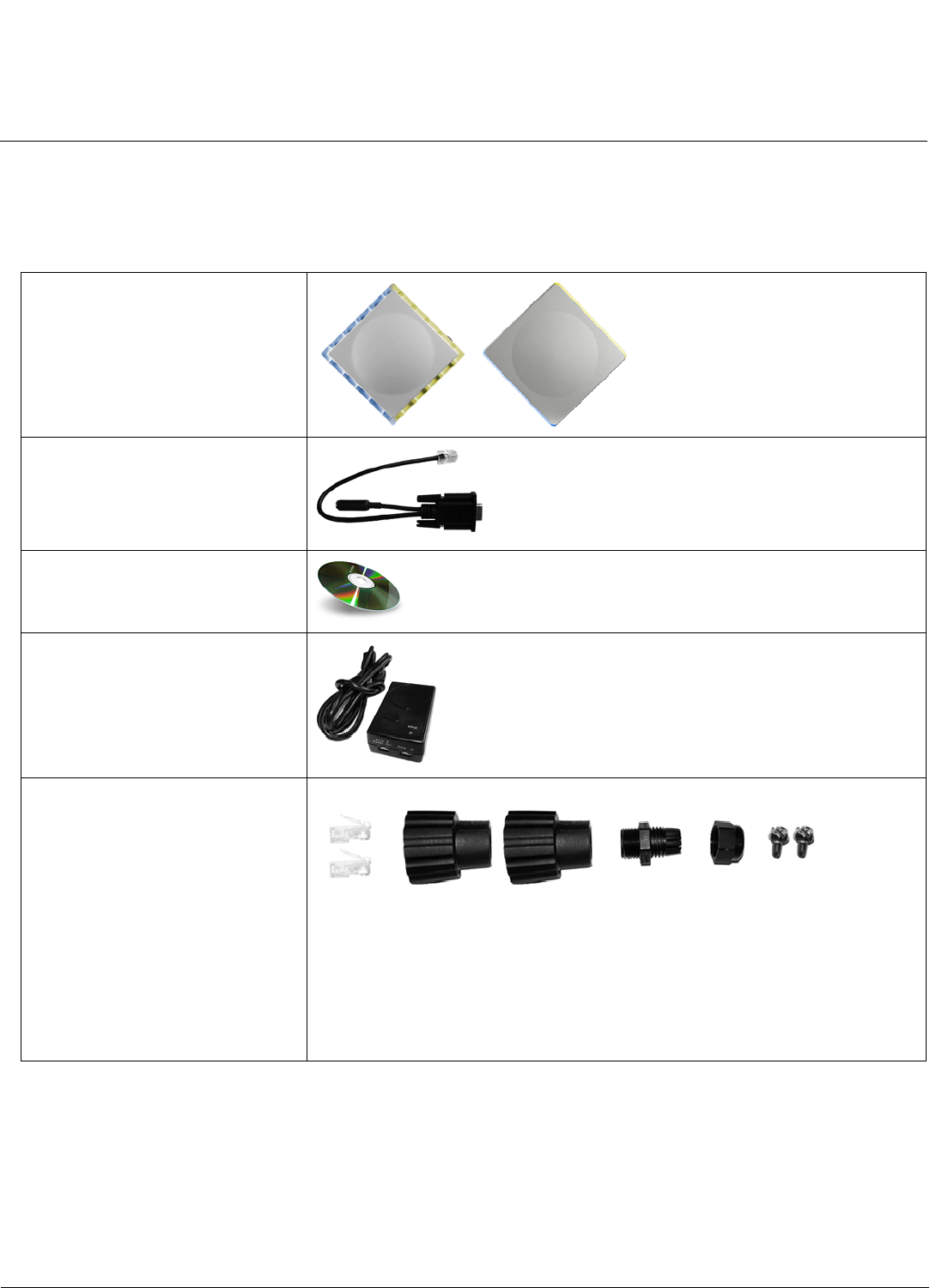
Product Package
Each Tsunami MP.16 shipment includes the items in the following table. Verify that you have received all parts of the
shipment.
NOTE: Cables are not supplied with the unit.
One of the following:
• BS / SS with external antenna
connector
• SS with Integrated Antenna
RJ45 to DB9 serial connector
(supplied with BS only) (1 ea.)
Installation CD (1 ea.)
Power Adaptor and Cord (1 ea.)
Cable Termination Kit Kit includes the following:
a. RJ45 connector
b. Sealing cap
c. Sealing nut
d. Lock nut
e. Grounding screws
ab cde
Installation and Initialization Tsunami MP.16 3650 System User Guide
Product Package
24
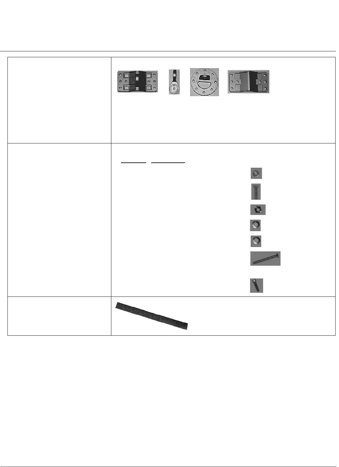
Mounting Kit Kit includes the following:
a. Mounting clamp for wall/pole
b. Extension arm
c. Mounting plate to enclosure
d. Mounting clamp for pole mounting
Mounting Hardware The following mounting hardware, included with the mounting kit:
Rubber Tape Strip
abc d
Quantity Description
6 ea. Plain washer #5/16
2 ea. Hex Cap Screw NC 5/16-18 x 35
2 ea. Nut NC 5/16-18
4 ea. Helical Spring Lock Washer #1/4
4 ea. Helical Spring Lock Washer #1/16
2 ea. Hex Cap Screw NC 5/16-18 x 80
4 ea. 68764, Screw, Machine, Pan,
Philips, 1/4"-20, 5/8"L
Installation and Initialization Tsunami MP.16 3650 System User Guide
Hardware Installation
25
Hardware Installation
This section describes the steps required to install and mount the unit, and to align the antenna. The installation
procedure does not include the mounting and connection of antennas. See the documentation the accompanies the
antenna and the Tsunami MP.16 3650 System Antenna Installation Guide for this information.
NOTE: Be sure to read the Release Notes file on the product CD as it contains software version and driver information
that may not have been available when this document was produced.
NOTE: Equipment is to be used with, and powered by, the power injector provided or by a power injector that meets
these requirements:
•UL-Listed/ITE (NWGQ)
•Limited Power Source Output per UL/IEC 60950
•CE-marked
•Approved for Power-over-Ethernet
•Rated output, 48 Vdc/0.67 A
•Pinout follows 802.3af standard for mid-span devices
See the following sections for installation instructions:
•Step 1: Choose a Location
•Step 2: Unpack Shipping Box
•Step 3: Assemble the Cable
•Step 4: Determine Proper Mounting Orientation
•Step 5: Assemble Mounting Hardware
•Step 6: Mount the Unit
•Step 7: Plug in the Cables
•Step 8: Power on the Unit
•Step 9: View LEDs
•Step 10: Align the Antenna
•Step 11: Tighten the Cables
IMPORTANT:
Before installing and using this product, see Safety and Regulatory Compliance Information on the
product CD.
IMPORTANT:
All units must be installed by a suitably trained professional installation technician or by a qualified
installation service.
WARNING:
To ensure proper grounding, use the hole at the bottom point on the back of each unit and the provided
grounding screws to attach a ground wire of at least 10 AWG stranded to each unit. Use proper wire
grounding techniques in accordance with local electric codes.


Installation and Initialization Tsunami MP.16 3650 System User Guide
Hardware Installation
27
Step 1: Choose a Location
To make optimal use of the unit, you must find a suitable location for the hardware. The range of the radio unit largely
depends upon the position of the antenna. Proxim recommends you do a site survey, observing the following
requirements, before mounting the hardware.
• The location must allow easy disconnection of power to the radio if necessary.
• Air must be able to flow freely around the hardware.
• The radio unit must be kept away from vibration and excessive heat.
• The installation must conform to local regulations at all times.
The units are designed to directly mount to a pole or wall. Using the supplied brackets and hardware, you can mount
them to a 1.25 inch to 4.5-inch pole (outside diameter). Using just one of the pole mounting brackets, you can mount the
units to a wall or other flat surface.
CAUTION: Proxim recommends the use of a lightning arrestor at the building ingress point. You can purchase the
Proxim Lightning Protector; see the documentation that comes with the Lightning Protector for more
information and installation instructions.
Step 2: Unpack Shipping Box
1. Unpack the unit and accessories from the shipping box.
2. Note the Ethernet and MAC addresses of the unit, as well as the serial number. The addresses may be used when
configuring the unit. The serial number is required to obtain support from Proxim. Keep this information in a safe
place.
Installation and Initialization Tsunami MP.16 3650 System User Guide
Hardware Installation
28
Step 3: Assemble the Cable
You will be attaching an outdoor-rated 24 AWG CAT5 cable (diameter .114 to .250 inches/2.9 to 6.4 mm) (not provided) to
the Power-over-Ethernet port on the back of the unit and waterproofing the assembly later in the installation procedure.
First, you must construct the cable and assemble the waterproofing cable covers as described in the following steps.
Proxim greatly simplifies this assembly process by offering pre-assembled CAT5 cable kits in 25m, 50m, and 75m lengths
(part numbers 69819, 69820, and 69821, respectively).
1. Slide the sealing nut (A) over the bare end of the CAT5 cable.
2. Slide the lock nut (B) over the bare end of the CAT5 cable.
3. Slide the sealing cap (C) over the bare end of the CAT5 cable. Make sure the red rubber gasket is inside the cap.
4. Apply two wraps of 0.5” wide Teflon tape (not supplied with unit) around the threads of the lock nut (B) that will go
inside the sealing cap.
5. Thread the lock nut (B) onto the sealing cap (C), and hand tighten.
6. Terminate the RJ45 connectors (D) to both ends of the CAT5 cable; test for proper wiring (cable should be a
straight-through cable).
NOTE:
•The cable must feed through all parts of the weatherproof cap before the RJ45 is crimped on the outdoor
Ethernet cable.
•The cable between the power injector and the unit must be a straight-through Ethernet cable (without
crossover).
•Due to variance in CAT5 cable diameter, termination techniques of the installer, and the application of proper
tightness of the connectors, it is strongly recommended that all cable connectors are secured by external
weatherproofing. This process will be described in Step 12: Weatherproof the Connectors.
BAC
Apply Teflon
tape here
D
Installation and Initialization Tsunami MP.16 3650 System User Guide
Hardware Installation
29
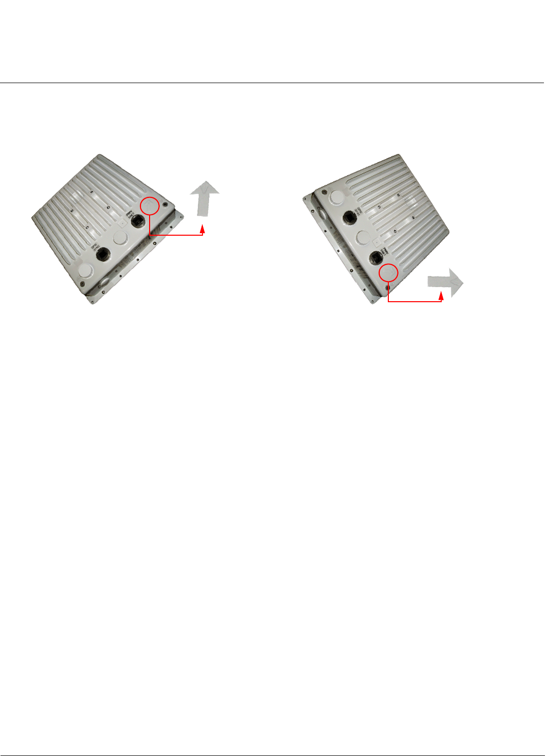
Step 4: Determine Proper Mounting Orientation
1. Locate the arrow on the back of the unit and determine your desired mounting orientation. For vertical polarization
using the integrated antenna, the arrow should be pointing up (perpendicular to the ground). For horizontal
polarization using the integral antenna, the arrow should be horizontal (parallel to the ground).
Vertical Polarization Horizontal Polarization

Installation and Initialization Tsunami MP.16 3650 System User Guide
Hardware Installation
30
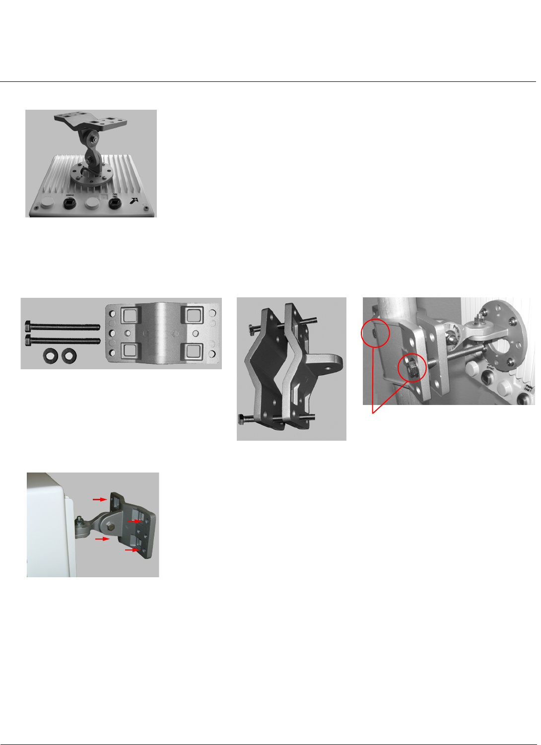
Step 5: Assemble Mounting Hardware
1. Attach the mounting plate (A) using the provided screws and washers (Torque 9 N.m/75 in-lbs), such that the unit’s
antenna will be vertically or horizontally polarized when mounted.
2. Attach the extension arm (B) to mounting piece (A) with the screw, nut, and washers provided, as shown below. The
extension arm gives the unit more possible tilt, letting you adjust for azimuth or elevation over a larger angle.
3. Attach the mounting bracket (C) to extension arm (B) with the screw, nut, and washers provided.
4. Tighten assembly (Torque 15 N.m/130 in-lbs).
A
Torque 9 N.m/75 in-lbs
B
A
B
C
Torque 15 N.m/130 in-lbs
Installation and Initialization Tsunami MP.16 3650 System User Guide
Hardware Installation
31
The following figure shows the full assembly attached to the unit:
Step 6: Mount the Unit
1. To pole-mount, insert the provided screws through bracket F. Fasten around the pole to bracket E and secure (Torque
11 N.m/100 in-lbs).
2. To wall-mount the unit, mount bracket E to the wall using 4 screws (not provided), as shown:
F
E
F
Torque 11 N.m/100 in-lbs
2 screws
Installation and Initialization Tsunami MP.16 3650 System User Guide
Hardware Installation
32
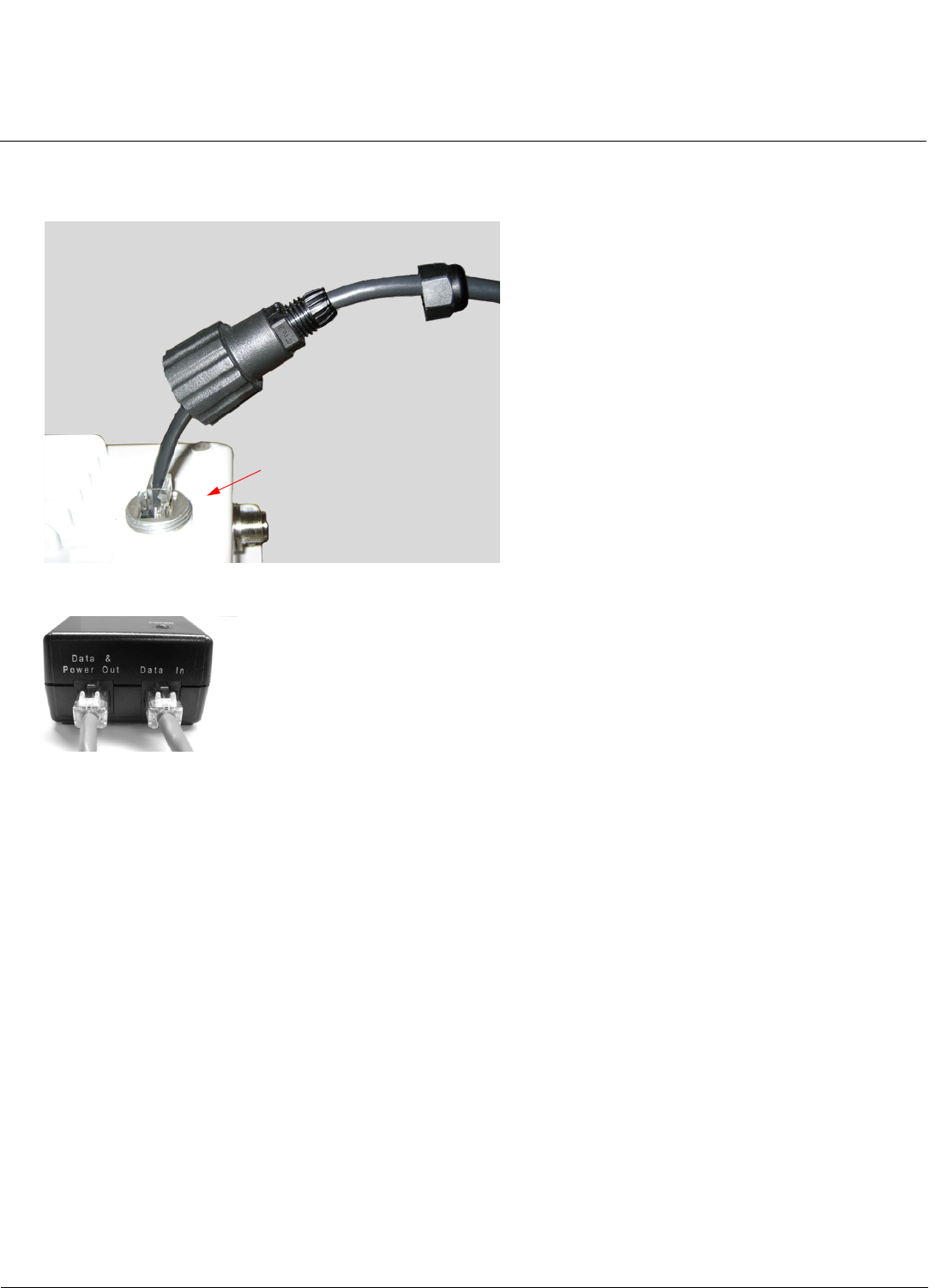
Step 7: Plug in the Cables
1. Plug one end of the CAT5 cable (A) into the RJ45 jack of the unit (B).
2. Connect the free end of the CAT5 cable to the “Data and Power Out” port on the power injector.
3. To connect the unit through a hub or a switch to a PC, connect a straight-through Ethernet cable between the
network interface card in the PC and the hub, and between the hub and the RJ45 “Data In” port on the PoE adapter.
To connect the unit directly to a PC, connect a cross-over Ethernet cable between the network interface card in the
PC and the RJ45 “Data In” port on the power injector.
A
B
Installation and Initialization Tsunami MP.16 3650 System User Guide
Hardware Installation
33
Step 8: Power on the Unit
Once you have connected the power injector to the Ethernet cabling and plugged the power injector cord into an AC
outlet, the unit is powered on. There is no ON/OFF switch on the unit. To remove power, unplug the AC cord from the AC
outlet or disconnect the RJ45 connector from the “Data and Power Out” port on the power injector.
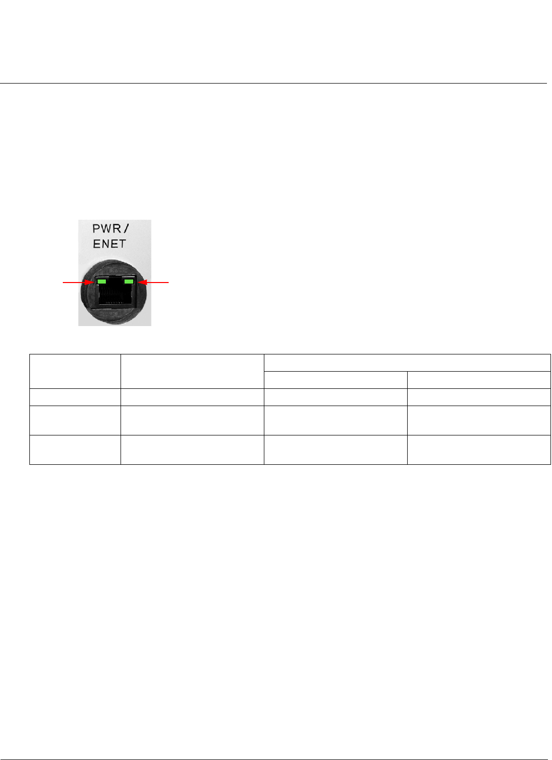
Step 9: View LEDs
When the unit is powered on, it performs startup diagnostics. When startup is complete, the LEDs show the unit’s
operational state. The LEDs are present at the unit’s Ethernet connector.
LEDs exhibit the following behavior:
LED State Ethernet LED RF (Wireless) LED
Base Station Subscriber Station
Off No Ethernet link. Radio is off. Radio is off.
On (solid green) Ethernet link is connected. Radio is active (transmitting
downlink and receiving uplink).
Downlink synchronized.
Flashing Packets are being received on
Ethernet.
Unit is in standby. Increasing on-off speed
indicates an increasing RSNR.
RF
LED
Ethernet
LED
Installation and Initialization Tsunami MP.16 3650 System User Guide
Hardware Installation
34
Step 10: Align the Antenna
Antenna alignment is the process of physically aligning the antenna of the radio receiver and transmitter to have the best
possible link established between them. The antenna alignment process is usually performed during installation and after
major repairs.
If you are installing external antennas, consult the documentation that accompanies the antenna for installation
instructions. Note that you must weatherproof the antenna connectors as described in Step 12: Weatherproof the
Connectors.
To ensure correct antenna alignment:
1. Perform a link budget calculation.
2. Compare the calculation to the SNR value on the SS by logging into the SS Web interface and clicking Monitor >
Statistics > MAC Statistics.
3. If needed, physically adjust the antenna, and refresh the Monitor > Statistics > MAC Statistics page to take a new
reading.
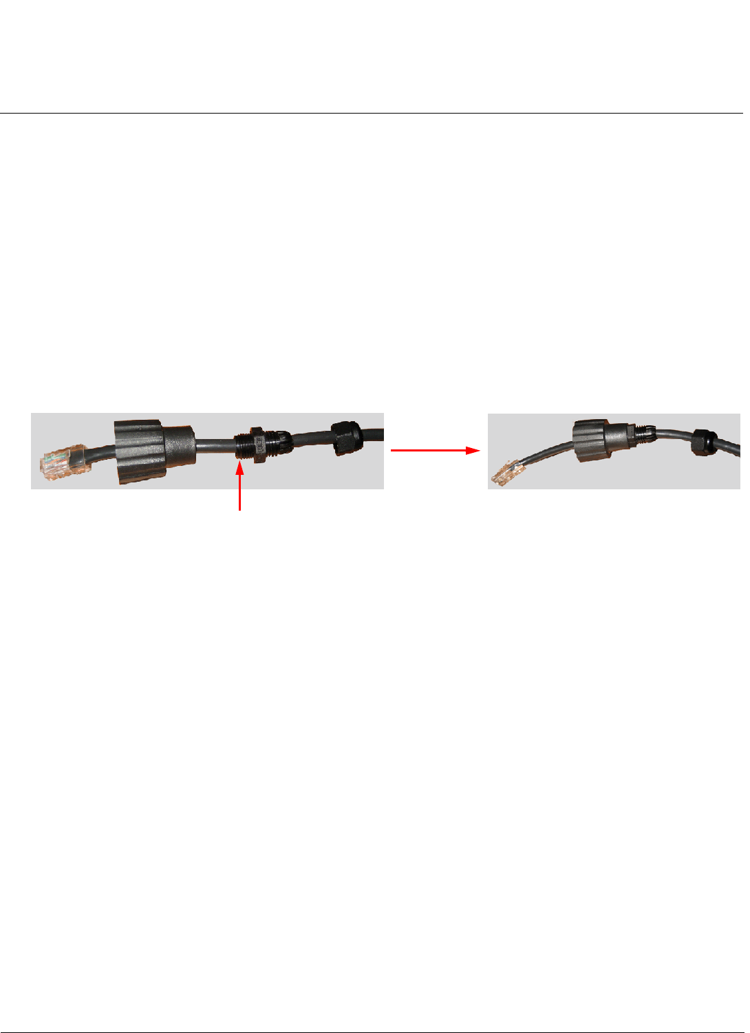
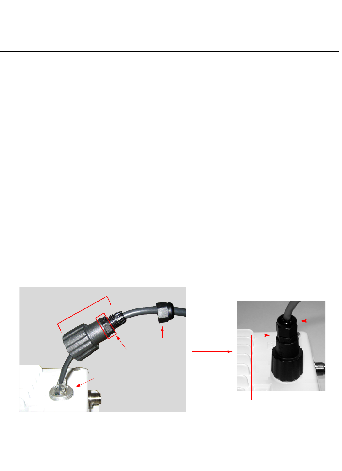
Step 11: Tighten the Cables
1. Apply two wraps of Teflon tape around the threads of the unit’s RJ45 jack (A) in a clockwise direction.
2. Make sure that the red rubber gasket is still seated in the sealing cap of the sealing cap/lock nut assembly (B);
3. Slide the sealing cap/lock nut assembly (B) over the RJ45 jack (A) and thread onto enclosure. Hand tighten first, then
use a pipe wrench or similar tool to tighten one more quarter turn.
CAUTION: Do not over-tighten!
4. Tighten the lock nut (C) (Torque 4 N.m/35 in-lbs).
5. Thread the sealing nut (D) onto the sealing cap/lock nut assembly (B) and tighten (Torque 3 N.m/25 in-lbs).
CAUTION: The lock nut (C) on the sealing cap/lock nut assembly (B) must be fully tightened over the RJ45 connector
before the sealing nut (D) is fully tightened. Otherwise, the Ethernet cable may twist and damage.
D
B
A (Apply Teflon
C
Torque 3 N.m/25 in-lbs
Torque 4 N.m/35 in-lbs
tape here)
Installation and Initialization Tsunami MP.16 3650 System User Guide
Hardware Installation
35
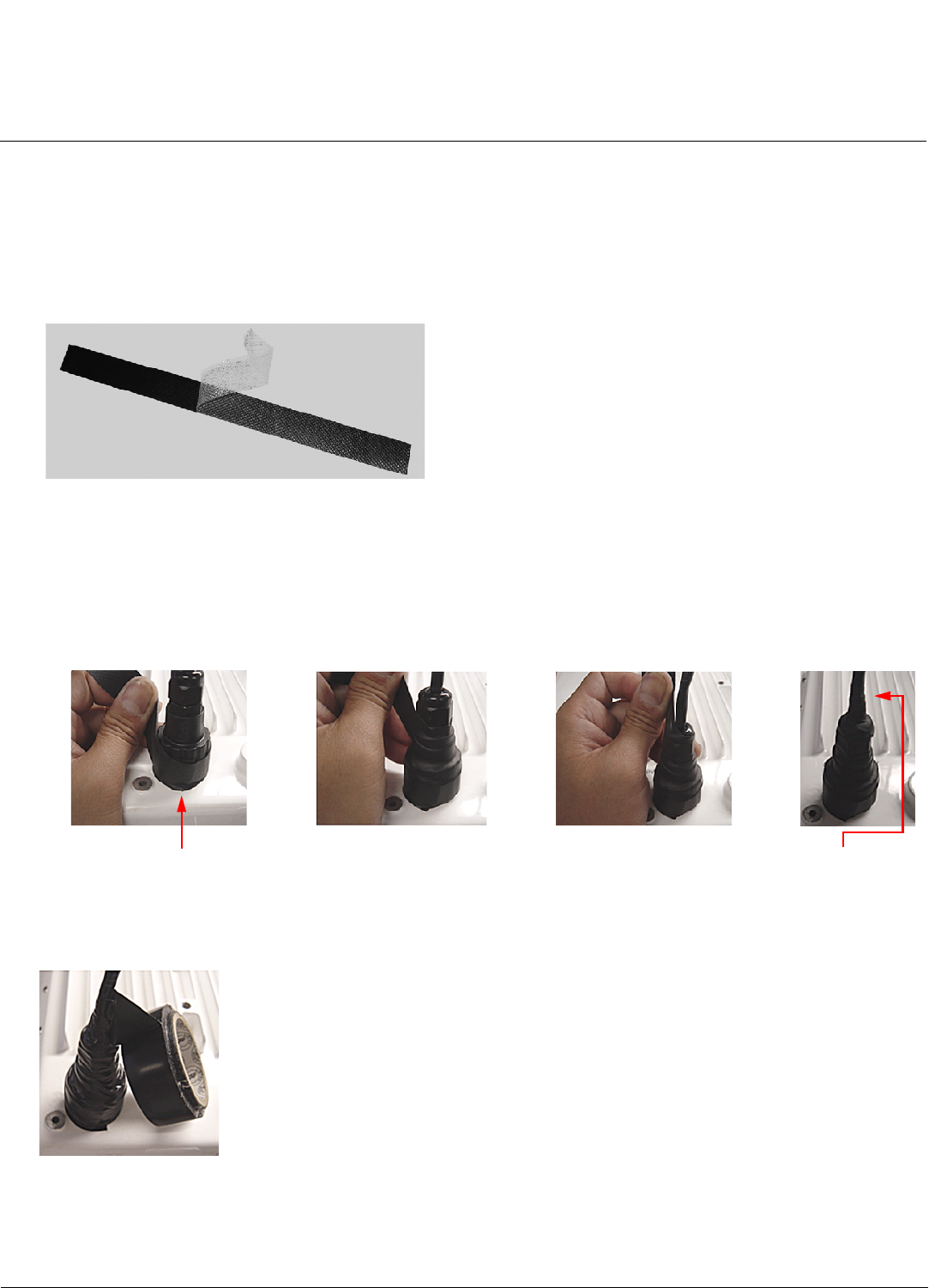
Step 12: Weatherproof the Connectors
After you have fully assembled and tightened the cable, use the provided self-fusing, rubber-based tape strip and
electrical tape (not provided; Proxim recommends Scotch™ Super 33+ Vinyl Electrical Tape) to seal the connection, as
follows.
1. Remove the film liner from the rubber-based tape strip, and stretch the tape until it is approximately half of its original
width. This activates the self-fusing action of the tape, which will set up over time to create a single, waterproof mass.
2. Stretch and wrap the tape around the connector tightly, starting below the connector cap and against the unit and
wrapping in a clockwise direction. Wrap the tape once around the base of the connector cap (A). Continue to wrap the
tape spirally around the connector in a clockwise direction, maintaining a 50% width overlap (B). Continue wrapping
the tape spirally upward (C) until the tape extends onto the cable and you have used the entire length of tape. Seal the
tape tightly against the connector and the cable (D).
NOTE: Be sure to wrap the tape in a clockwise direction; wrapping the tape in a counterclockwise direction may
loosen up the connector.
3. In the same manner as described in Step 2 above, apply a layer of black electrical tape (not provided) over the
rubber-based tape for further protection. Make sure the electrical tape also extends beyond the rubber-based tape to
seal it.
4. Repeat the weatherproofing procedure for other connectors as appropriate.
ABCD
Start below connector cap Continue onto cable

Installation and Initialization Tsunami MP.16 3650 System User Guide
Hardware Installation
36
Step 13: Install Documentation and Software
To install the documentation and software on a computer or network:
1. Place the installation CD in a CD-ROM drive. The installer normally starts automatically. (If the installation program
does not start automatically, double click setup.exe on the installation CD.)
2. The following documentation and software products are installed:
• Available from Start > All Programs > Tsunami > MP.16 3650:
– Documentation (in Docs subdirectory):
• User Guide
• Quick Installation Guide
• Safety and Regulatory Guide
• Recommended Antenna Guide
• Antenna Installation Guide
– MP.16 3650 Online Help
NOTE: All of these items are also available from C:\Program Files\Tsunami\MP.16 3650.
• Available from C:\Program Files\Tsunami\MP.16 3650:
– Documentation (in Docs folder): See list above
– Help files (in Help folder; click on index.htm to access)
– MIB files (in MIBs folder)
– TFTP Server (in Extras folder)
Installation and Initialization Tsunami MP.16 3650 System User Guide
Using the Web Interface
37
Using the Web Interface
Logging In
You may use your web browser to monitor and configure the radio unit. To configure and monitor the unit using the
command line interface, see Command Line Interface.
1. Open a Web browser on a network computer.
2. Enter the unit’s IP address in the browser’s Address field and press Enter or Go.
•The default IP address of the BS is 192.168.10.1.
•The default IP address of the SS is 192.168.10.2.
NOTE: The unit must be on the same subnet as your network computer. The default subnet for the BS is
255.255.254.0; the default for the SS is 255.255.255.0.
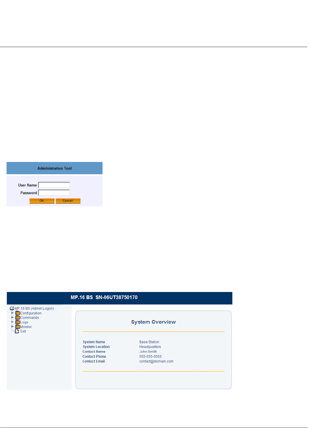
The login page is displayed.
Figure 2-3 Enter Network Password
3. Log in as follows:
• To log in as an administrator, enter “admin” in the User Name field. Enter the password in the Password field.
For new units, the default administrator password is public.
• To log in as a user, enter “user” in the User Name field. Enter the password in the Password field. For new units,
the default password is public.
NOTE: To change passwords via the web interface, see Passwords in the Commands on BS/SS chapter. To change
passwords through the CLI, see Passwd Command in the Command Line Interface chapter.
Upon successful login, the System Overview page is displayed, containing read-only information about your BS or SS.
Figure 2-4 System Overview Page (Base Station)
You can configure many of the parameters displayed on this page from the System Configuration page. To return to
this page at any time, click MP.16 BS (Admin Logon) or MP.16 SS (Admin Logon) on the menu.
Installation and Initialization Tsunami MP.16 3650 System User Guide
Using the Web Interface
38
4. Click on any of the menu items on the left side of the screen to begin configuring the unit.
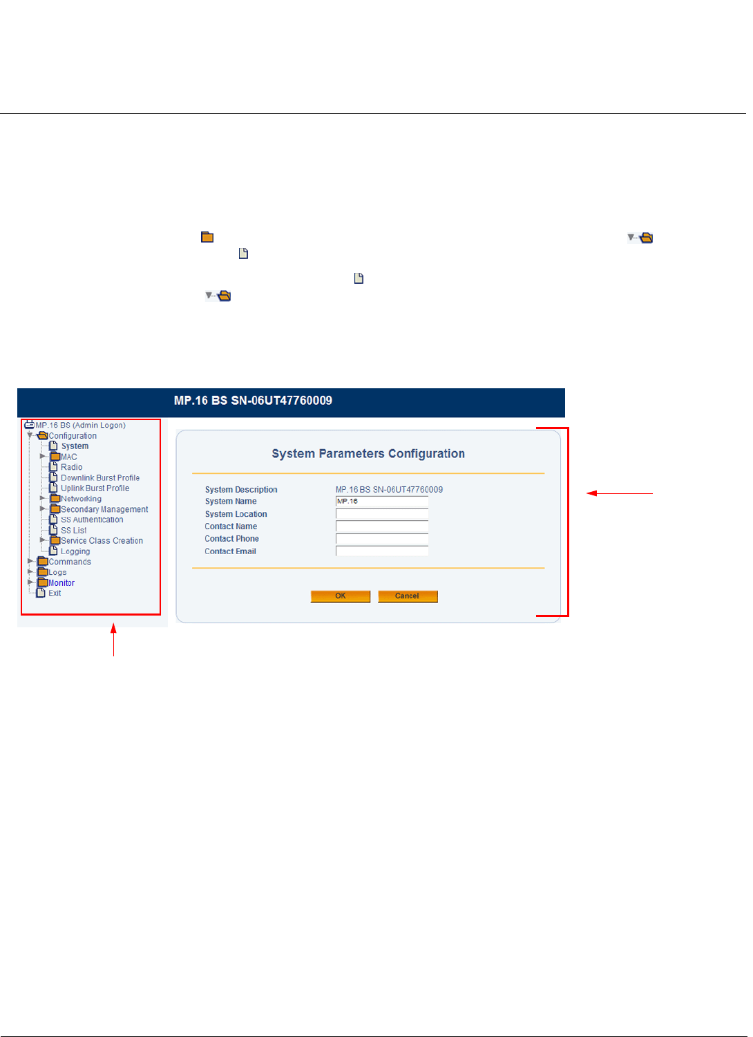
Web Interface Navigation
The Web interface screen contains two sections (see Figure 2-5):
• Menu: Use the collapsible menu on the left of your screen to navigate through the web interface. For headings
(marked with a folder icon: ) click on the arrow to the left of the heading to expand its contents ( ). Configuration
pages (marked with a page icon: ) are used for configuring the unit.
NOTE: You must click on an item with a page icon ( ) to display configuration parameters; if you click on an
expanded heading ( ), the screen will not update.
• Configuration parameters: View and change the unit’s settings in the “work area.” Enter required or desired values in
available fields, or use drop down menus to make selections. When you have configured a page, you must click the
OK button to save your changes. If you do not click the OK button, the configuration parameters you specified will not
be set.
Figure 2-5 Web Interface Screen (Base Station)
Configuration/Monitoring
parameters
Menu
Installation and Initialization Tsunami MP.16 3650 System User Guide
Installing Latest Software
39
Installing Latest Software
Proxim periodically releases updated software for the Tsunami MP.16 3650 system on its support Web site,
http://support.proxim.com. Proxim recommends that you check the Web site for the latest updates after you have
installed and initialized the unit.
Download Software
1. Contact Technical Services and Support to obtain the newest software.
2. Store the downloaded software in your TFTP server’s directory.
3. Install the software via TFTP using the Web interface or the Command Line Interface, as described below.
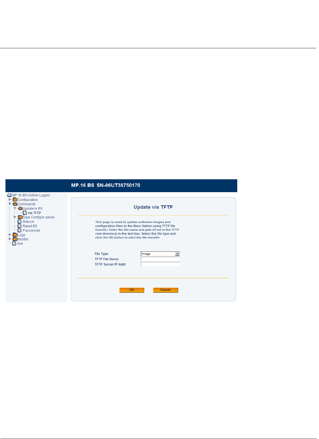
Install Software from your TFTP Server using the Web Interface
1. Log in to the BS or SS
2. Click Commands > Update to BS or Update to SS > via TFTP
The Update Via TFTP page is displayed, as shown below.
Figure 2-6 Update via TFTP Screen
3. From the File Type drop-down menu, select Image.
4. Enter the name of the downloaded software file (including the file extension) in the TFTP File Name field. This file
must be in the TFTP server’s local root directory.
5. Enter the IP address of your TFTP server in the TFTP Server IP Addr field.
6. Click OK.
The download will begin, and image will be downloaded to the unit
7. Click Configuration > Commands > Reboot.
8. Click Reboot.
Install Software from your TFTP Server using the CLI
1. Open the CLI interface to the BS or SS via Telnet or a serial connection.
2. Enter your username and password when prompted.

Installation and Initialization Tsunami MP.16 3650 System User Guide
Installing Latest Software
40
3. Enter the following command: download <TFTP Server Address> <File Name> image
(e.g.: download 172.168.12.50 newimage.bin image)
The download will begin, and the image will be downloaded to the unit.
4. When the download is complete, type reboot and press Enter.

Installation and Initialization Tsunami MP.16 3650 System User Guide
First Configuration
41
First Configuration
The MP.16 system operates with little required setup. However, the administrator must initially configure certain
parameters to allow the BS and SS to communicate and (if desired) to secure the network.
The following parameters must be set in order for the units to communicate:
•Center frequency: On the BS and SS Web interfaces, click Configuration > Radio to set the desired frequency.
See the following:
–Radio Configuration in the Base Station Configuration chapter
–Radio Configuration in the Subscriber Station Configuration chapter.
The following parameters must be set to ensure that the network is secure:
•IP address:
– On the BS Web interface, click Configuration > Networking > Basic to set the IP address. See Networking
Configuration in the Base Station Configuration chapter.
– On the SS Web interface, click Configuration > Network to set the IP address. See Networking Configuration in
the Subscriber Station Configuration chapter.
•Passwords: On the BS Web interface, click Commands > Passwords to set HTTP and CLI passwords. See
Passwords in the Commands on BS/SS chapter.
•Net Entry mode: On the BS Web interface, click Configuration > SS Authentication to set the Net Entry Mode. See
Subscriber Station Authentication in the Base Station Configuration chapter.
More information and advanced configuration options can be found as follows:
• For information and advanced Web-based configuration on the BS, including the use of Service Classes, see Base
Station Configuration.
• For information and advanced Web-based configuration options on the SS, see Subscriber Station Configuration.
• For information on configuration via the CLI, see Command Line Interface.

42
Tsunami MP.16 3650 System User Guide
3
Base Station Configuration
Introduction
In the Tsunami MP.16 multipoint system all radios within a sector can be centrally configured from the Base Station.
Besides BS and SS configuration, the Base Station Configuration menu includes the authentication and registration of
SSs, the assignment of pre-defined SS Classes to those SSs, the creation of new SS Classes, and other service
defining parameters.
After logging in to the BS, you can access the following configuration pages:
•System Configuration
•MAC Configuration
–Basic MAC Configuration
–Advanced MAC Configuration
•Radio Configuration
•Radio Downlink Burst Profile Configuration
•Radio Uplink Burst Profile Configuration
•Networking Configuration
–Basic Networking
–VLANs
•VLAN Modes: Introduction
•VLAN ID List
•Configuring the BS for Transparent VLAN Mode
•Configuring the BS for Trunk VLAN Mode
–Bridging
– RADIUS Servers
– Syslog
•Overview
•Syslog Configuration
•Syslog Host Table
– Trap Hosts
– Static Routes
•Global Positioning System (GPS)
– TFTP Table
–DHCP Server
•Subscriber Station Authentication
•Subscriber Station List
–Subscriber Station List Configuration
•Service Class Creation
–Introduction
–Subscriber Station Classes: Overview
–Service Class Creation
•PIR Creation

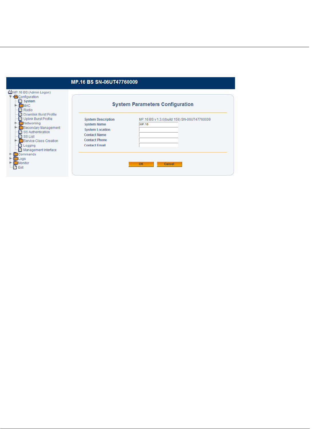
Base Station Configuration Tsunami MP.16 3650 System User Guide
System Configuration
44
System Configuration
The System Configuration page allows you to set and view BS-specific identification, location, and contact information.
Figure 3-1 System Configuration Parameters
The following parameters can be configured or viewed from the System Configuration page:
•System Description: A read-only description of the Base Station, including software version and build information.
•System Name: The name assigned to BS. Enter a value between 1 and 255 alphanumeric characters.
•System Location: The location where the BS is installed. Enter a value between 1 and 255 alphanumeric characters.
•Contact Name: The name of the person responsible for the BS. Enter a value between 1 and 255 alphanumeric
characters.
•Contact Email: The email address of the person responsible for the BS. Enter a value between 1 and 255
alphanumeric characters.
•Contact Phone: The telephone number of the person responsible for the BS. Enter a value between 1 and 255
alphanumeric characters.
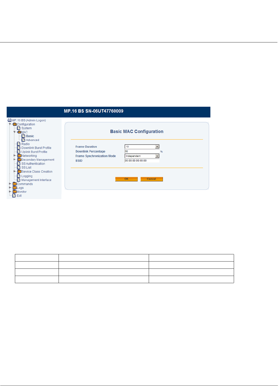
Base Station Configuration Tsunami MP.16 3650 System User Guide
MAC Configuration
45
MAC Configuration
The MAC controls access to the wireless media. MAC configuration allows administrators to tune their 802.16 MAC
implementation based on the needs of their network environment. The following sections provide more information:
•Basic MAC Configuration
•Advanced MAC Configuration
Basic MAC Configuration
Figure 3-2 Basic MAC Screen
The following basic MAC parameters may be set or viewed:
•Frame Duration: The maximum frame length. Set the frame length to 5, 10, or 20 ms.
•Downlink Percentage: This parameter sets the downlink/uplink boundary of the TDD frame by setting the percentage
of bandwidth allocated to the downlink. Set the downlink percentage to a value between 10%-90% depending on the
frame duration (see the following table). The remainder will be allocated to the uplink.
•Frame Synchronization Mode: Set this parameter to Independent.
•BSID: A 48-bit value, defaulting to 1. Set this to a unique value for each BS, where the upper 24 bits equal the
Operator ID. Contact the IEEE Registration Authority to for an Operator ID. If one can not be obtained, use a 24-bit
random number until one can be obtained.
Frame Duration Minimum Downlink Percentage Maximum Downlink Percentage
5 ms 40% 50%
10 ms 40% 70%
20 ms 40% 70%
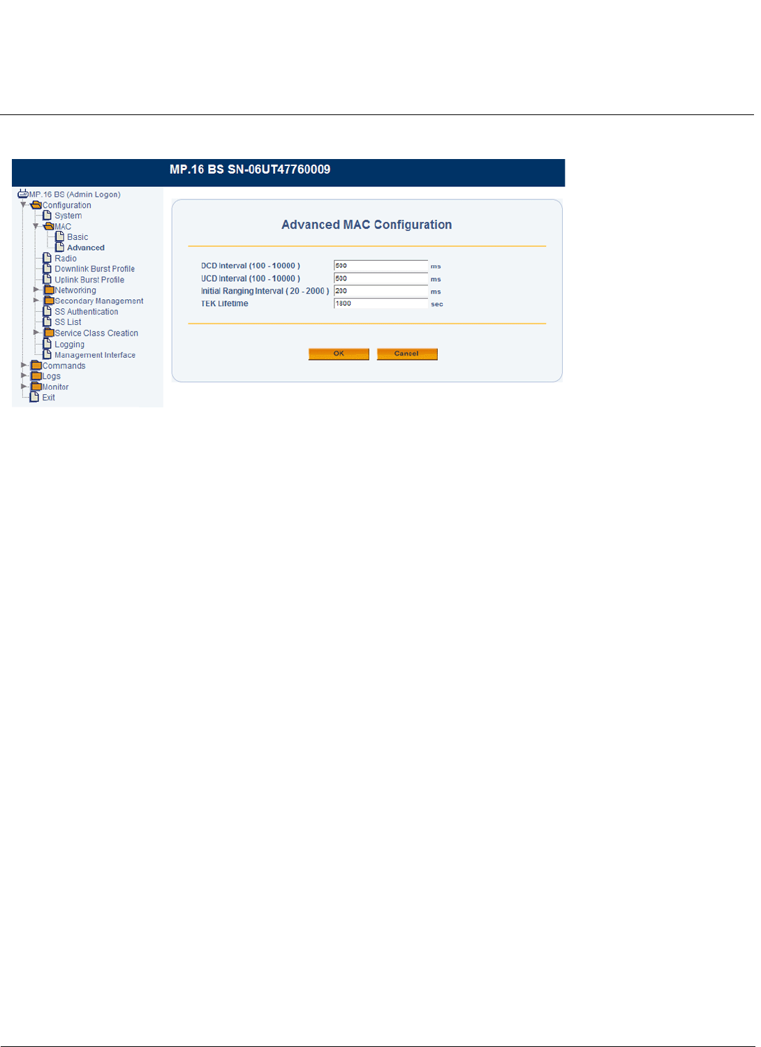
Base Station Configuration Tsunami MP.16 3650 System User Guide
MAC Configuration
46
Advanced MAC Configuration
Figure 3-3 Advanced MAC Screen
The following advanced MAC parameters may be set or viewed:
NOTE: These parameters should be modified only by experienced users. Please refer to the IEEE 802.16-2004
standard.
•DCD Interval: Time between the transmissions of Downlink Channel Descriptor (DCD) messages. Setting this value
high saves bandwidth, but it may take longer for an SS to enter the network. Enter a value between 100 - 10000
milliseconds.
•UCD Interval: Time between the transmissions of Uplink Channel Descriptor (UCD) messages. Setting this value high
saves bandwidth, but it may take longer for an SS to enter the network. Enter a value between 100 - 10000
milliseconds.
•Initial Ranging Interval: Time between initial ranging requests. Setting this value high saves bandwidth, but it may
take longer to enter the network. Enter a value between 20-2000 milliseconds.
•TEK Lifetime: The length of time that a Traffic Encryption Key is valid. Minimum value is 30 minutes; maximum is 7
days. The default is 30 minutes.
•GPS Sync: Enables or disables synchronization of transmission and reception periods with co-located base stations.
The GPS accessory must be attached to the BS in order for synchronization to operate.
CAUTION: When GPS Sync is enabled, all BSs in an area must use the same frame duration and uplink/downlink
modulation.
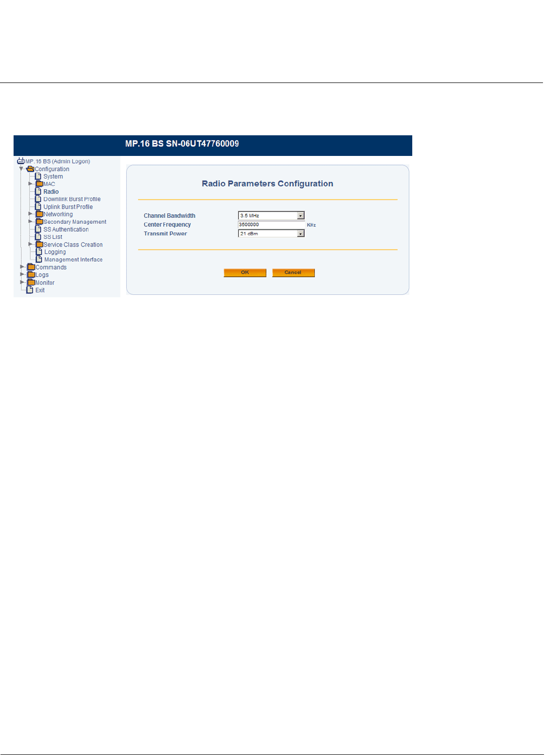
Base Station Configuration Tsunami MP.16 3650 System User Guide
Radio Configuration
47
Radio Configuration
The BS radio controls the channel bandwidth and frequency, as well as the transmit power.
Figure 3-4 Radio Configuration Parameters
The following parameters may be set or viewed:
•Channel Bandwidth: Set to 3.5 MHz or 7 MHz.
•Center Frequency: Set the desired center frequency.
•Transmit Power: Set the downlink transmit power to a value between 5 - 21 dBm. The default is 21 dBm.

Base Station Configuration Tsunami MP.16 3650 System User Guide
Radio Downlink Burst Profile Configuration
48
Radio Downlink Burst Profile Configuration
From the Radio Downlink Burst Profile page, you can enable or disable modulation rates.
Figure 3-5 Radio Downlink Burst Profile Configuration Parameters
Enable or disable any of the following rates:
• BPSK-1/2
• QPSK-1/2
• QPSK-3/4
• 16-QAM-1/2
• 16-QAM-3/4
• 64-QAM-2/3
• 64-QAM-3/4
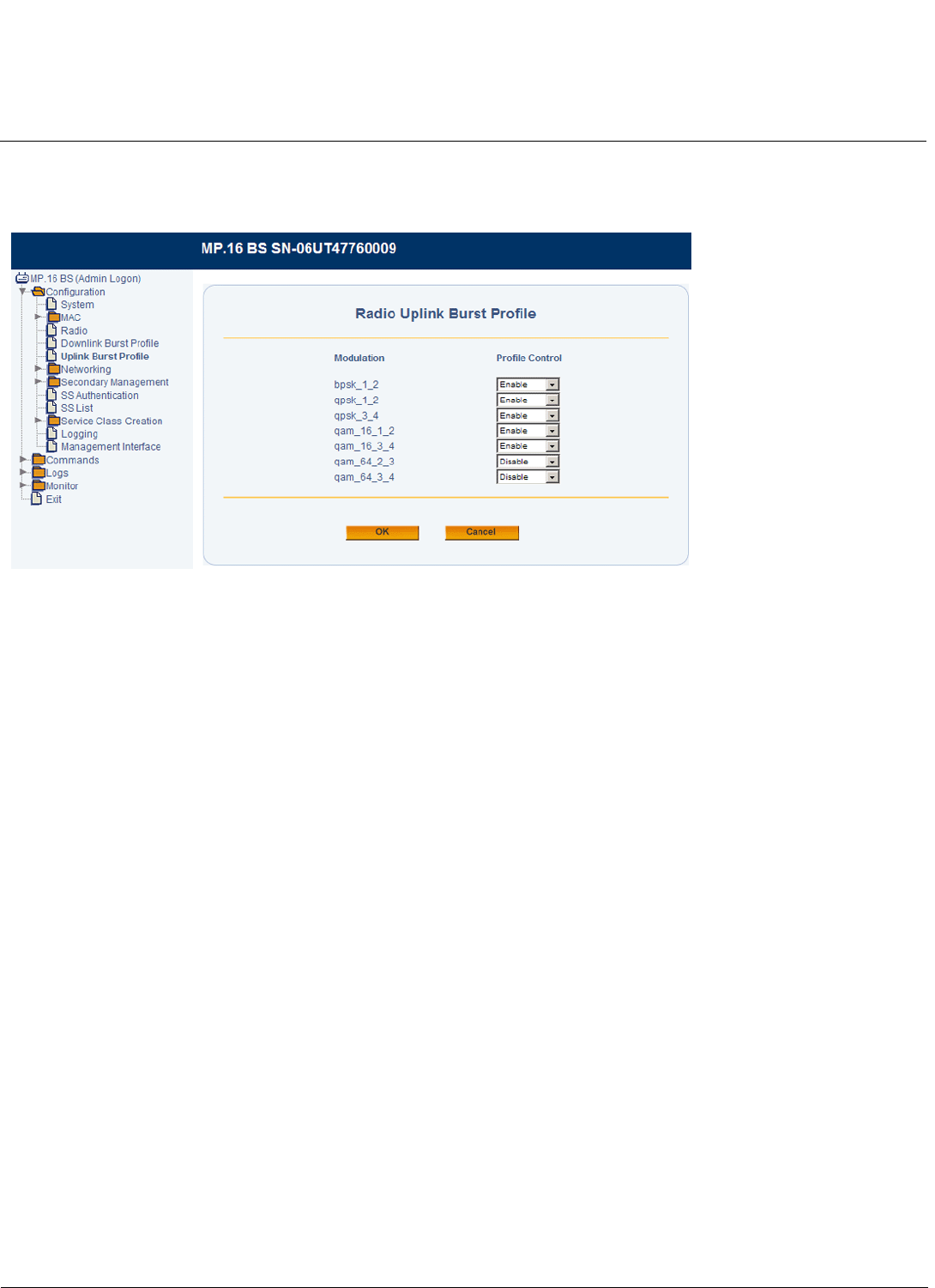
Base Station Configuration Tsunami MP.16 3650 System User Guide
Radio Uplink Burst Profile Configuration
49
Radio Uplink Burst Profile Configuration
From the Radio Uplink Burst Profile page, you can enable or disable modulation rates.
Figure 3-6 Uplink Burst Profile Configuration Parameters
Enable or disable any of the following rates:
• BPSK-1/2
• QPSK-1/2
• QPSK-3/4
• 16-QAM-1/2
• 16-QAM-3/4
• 64-QAM-2/3
• 64-QAM-3/4
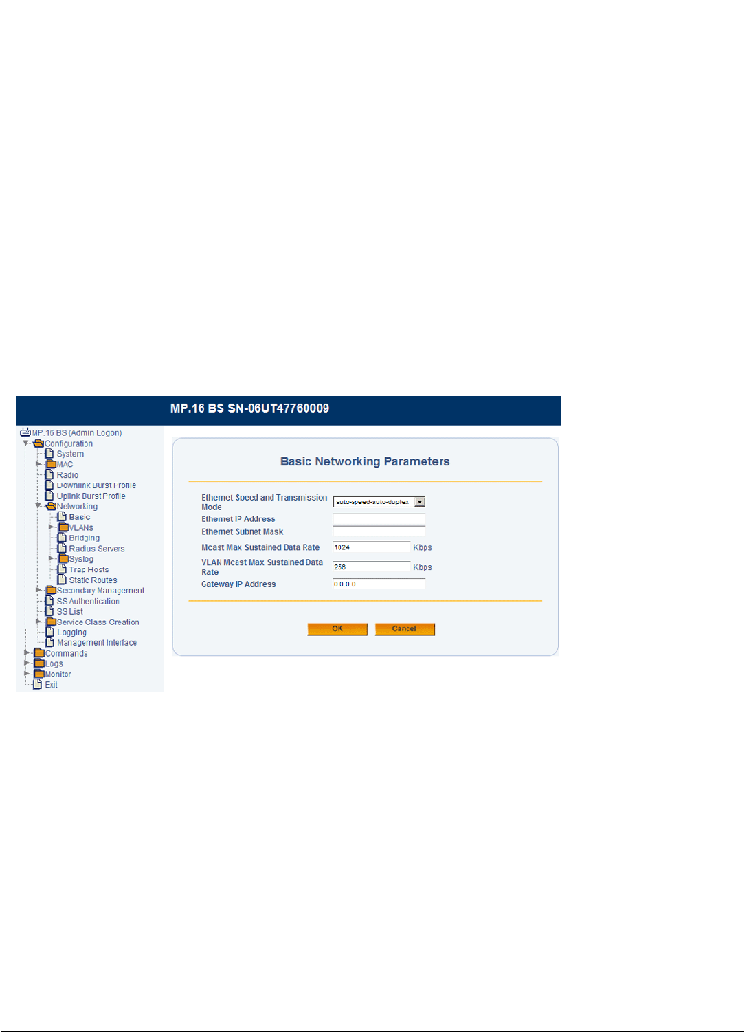
Base Station Configuration Tsunami MP.16 3650 System User Guide
Networking Configuration
50
Networking Configuration
Network configuration includes the following:
•Basic Networking
•VLANs
•Bridging
•RADIUS Servers
•Syslog
•Trap Hosts
•Static Routes
Basic Networking
Basic networking configuration involves setting the parameters of the BS’s Ethernet interface.
Figure 3-7 Basic Networking Parameters
The following parameters may be set or viewed:
•Ethernet Speed and Transmission Mode: This parameter is set to auto-speed-auto-duplex. It is not configurable.
•Ethernet IP Address: Set the static IP address of the BS. The default IP address of the BS is 192.168.10.1.
•Ethernet Subnet Mask: Set the subnet mask to which the unit is connected. The default mask is 255.255.255.0.
•Mcast Max Sustained Data Rate: Set the maximum sustained data rate on multicast packets. This parameter can be
set to unlimited, or to a value between 8 - 8192 Kbps (in multiples of 8 Kbps).
•VLAN Mcast Max Sustained Data Rate: Set the maximum sustained data rate on multicast packets sent across a
VLAN. This parameter can be set to unlimited, or to a value between 8 - 1024 Kbps (in multiples of 8 Kbps).
•Gateway IP Address: Enter the IP address of a gateway on the network.

Base Station Configuration Tsunami MP.16 3650 System User Guide
Networking Configuration
51
VLANs
Virtual Local Area Networks (VLANs) are logical groupings of network resources behind one or more BS and SS.
Groupings are based on VLAN IDs. If a data packet is tagged with a VLAN ID, it is called a VLAN-tagged packet. If there
is no VLAN ID, the packet is called an untagged packet. All VLAN IDs must be stored in the VLAN ID List. Up to 256
individual VLAN IDs may be stored in this list.
See VLAN Modes: Introduction for detailed information on MP.16 operation in each of these modes.
See VLAN ID List for VLAN ID List configuration instructions.
See Bridging for VLAN Mode configuration instructions.
VLAN Modes: Introduction
Depending on the VLAN capabilities of sub-networks and devices behind the BS and SS, you can configure the BS and
SS for various VLAN modes.
The BS can be configured to operate in one of three VLAN modes:
• Transparent
•Trunk
•Mixed
Depending on the BS mode selected, the SS can be configured to operate in one of four VLAN modes:
• Transparent: Available when the BS is in Transparent mode.
• Trunk: Available when the BS is in Trunk mode.
• Access: Available when the BS is in either Transparent or Trunk mode.
• Mixed: Available when the BS is in Trunk mode.
See the following sections for more information on the functionality of each mode.
BS in Transparent Mode
When the BS is in Transparent mode, the SS may be in either Transparent or Access mode.
When both the BS and SS are in Transparent mode VLAN-tagged or untagged packets are accepted and forwarded by
the BS and SS, unless they are discarded due to PIR restrictions (see Networking Parameters in the Service Class
Creation section). The BS and SS will process both tagged and untagged packets from both the wireless and Ethernet
interfaces.
When the BS is in Transparent mode and the SS is in Access mode, the SS processes only untagged packets from the
Ethernet interface, discarding any tagged packets it receives. Upon receiving an untagged packet, the SS tags it with an
assigned VLAN ID and priority provisioned by the BS. When the SS receives tagged packets from the wireless interface,
it removes the VLAN tag and sends only untagged packets to the Ethernet interface.
Figure 3-8 illustrates the exchange of packets when the BS is in Transparent mode and registered SSs are in either
Transparent or Access mode. Ta b l e 3 - 1 provides a detailed summary of BS and SS functionality when the BS is in
Transparent mode.
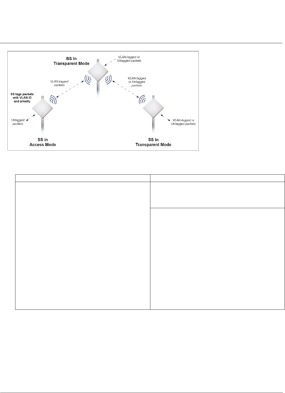
Base Station Configuration Tsunami MP.16 3650 System User Guide
Networking Configuration
52
Figure 3-8 BS in Transparent Mode
Table 3-1 BS in VLAN Transparent Mode—Summary
BS in Trunk Mode
When the BS is in Trunk mode, the SS may be in either Trunk, Access, or Mixed mode.
When both the BS and SS are in Trunk mode, packets are forwarded only if they are tagged with one of the allowed
VLAN IDs configured on the BS or provisioned to the SS. Any untagged frames, and any frames with a tag that is not
found in the VLAN ID List, are discarded.
When the BS is in Trunk mode and the SS is in Access mode, the SS processes only untagged packets from the Ethernet
interface, discarding any tagged packets it receives. Upon receiving an untagged packet, the SS tags it with an assigned
VLAN ID and priority provisioned by the BS. When the SS receives tagged packets from the wireless interface, it removes
the VLAN tag and sends only untagged packets to the Ethernet interface.
BS in Transparent VLAN Mode SS in Transparent or Access VLAN Mode
• BS forwards both tagged and untagged frames
• BS allows any untagged management frames to
access the device
Transparent Mode:
• SS forwards both tagged and untagged frames
• SS allows any untagged management frames to
access the device
Access Mode:
• SS discards any tagged framed received from the
Ethernet interface
• SS tags any untagged frames received from the
Ethernet interface with the configured VLAN ID and
priority and forwards them to the BS
• SS untags all frames received from the BS that are
tagged with the VLAN ID and forwards them to the
Ethernet Interface or to the internal IP address.
• SS discards any frames received from the BS with a
tag other than the VLAN ID
• SS tags any management frames that it generates with
the configured VLAN ID and priority when sending
them on the wireless interface
• SS sends all management frames as untagged when
sending them on the Ethernet interface
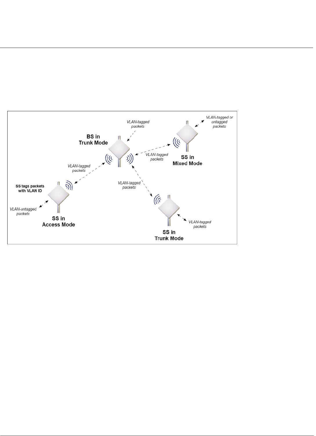
Base Station Configuration Tsunami MP.16 3650 System User Guide
Networking Configuration
53
When the BS is in Trunk mode and the SS is in Mixed Mode, the SS processes tagged and untagged packets. Upon
receiving an untagged packet, the SS tags it with an assigned VLAN Access ID and priority provisioned by the BS. Upon
receiving a tagged packet, the SS forwards it only if its tag matches the configured VLAN Access ID or one of the VLAN
IDs configured in the VLAN ID Trunk list.
Figure 3-9 illustrates the exchange of packets when the BS is in Trunk mode and registered SSs are in either Trunk,
Access, or Mixed mode. Ta b l e 3 - 2 provides a detailed summary of BS and SS functionality when the BS is in Trunk
mode.
Figure 3-9 BS in Trunk Mode

Base Station Configuration Tsunami MP.16 3650 System User Guide
Networking Configuration
54
Table 3-2 BS in VLAN Trunk Mode—Summary
BS in Trunk VLAN Mode SS in Trunk or Access VLAN Mode
• BS discards all untagged frames received from the
Ethernet interface or from any of the associated SSs.
• BS forwards frames received from the Ethernet
interface or from any associated SS that are tagged
with the configured VLAN IDs
• The BS tags all management frames that it generates
with the configured Management VLAN ID and priority
• The BS allows only management frames tagged with
the configured Management VLAN ID to access it.
Trunk Mode:
• SS discards all untagged frames received from the
Ethernet interface or from the BS.
• SS forward only frames received from the Ethernet
Interface or from the wireless interface that are tagged
with the configured VLAN IDs; it discards all other
tagged frames.
• SS tags any management frames that it generates with
the configured Management VLAN ID and priority
• SS allows only management frames tagged with the
configured Management VLAN ID to access it
Access Mode:
• SS discards any tagged framed received from the
Ethernet interface
• SS tags any untagged frames received from the
Ethernet interface with the configured VLAN ID and
priority and forwards them to the BS
• SS untags all frames received from the BS that are
tagged with the VLAN ID and forwards them to the
Ethernet Interface or to the internal IP address.
• SS discards any frames received from the BS with a
tag other than the VLAN ID
• SS tags any management frames that it generates with
the configured VLAN ID and priority when sending
them on the wireless interface
• SS sends all management frames as untagged when
sending them on the Ethernet interface
Mixed Mode:
• SS tags any untagged frames received from the
Ethernet interface with the configured VLAN Access ID
and priority and forwards them to the BS
• When it receives a tagged from the Ethernet or
Wireless interface, the SS forwards only frames that
are tagged with the VLAN IDs configured in the Trunk
list; it discards all other tagged frames.
• SS untags all frames received from the BS that are
tagged with the VLAN Access ID and forwards them to
the Ethernet Interface or to the internal IP address.
• SS tags any management frames that it generates with
the configured VLAN Access ID and priority when
sending them on the wireless interface
• SS sends all management frames as untagged when
sending them on the Ethernet interface
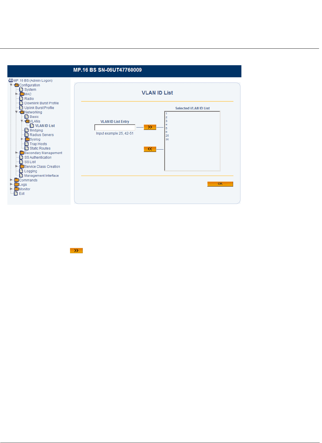
Base Station Configuration Tsunami MP.16 3650 System User Guide
Networking Configuration
55
VLAN ID List
Figure 3-10 VLAN ID List Configuration
To configure the VLAN ID List:
1. Enter a number or range of numbers between 1 and 4095 in the VLAN ID List Entry field. Up to 256 entries may be
added to the VLAN ID List.
2. Click the right arrow . To remove a VLAN ID from the list, select it and click the left arrow.
Bridging
From the Bridging Parameters page, you can set the VLAN mode and associated bridging parameters for the BS. See
the following sections:
•Configuring the BS for Transparent VLAN Mode
•Configuring the BS for Trunk VLAN Mode
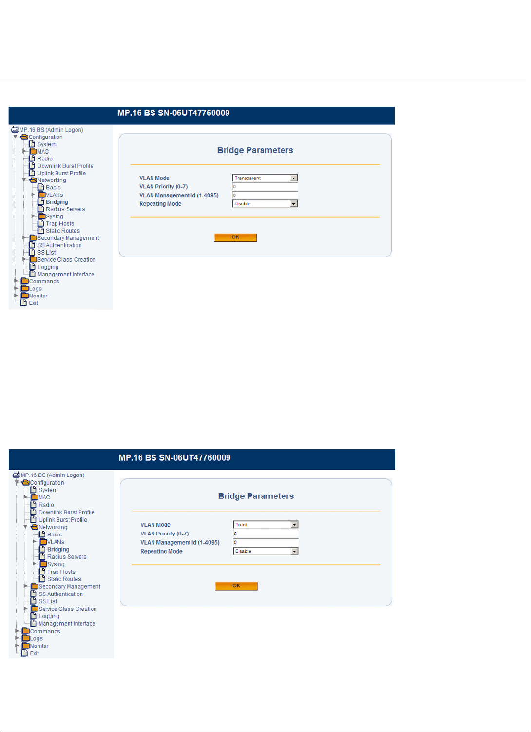
Base Station Configuration Tsunami MP.16 3650 System User Guide
Networking Configuration
56
Configuring the BS for Transparent VLAN Mode
Figure 3-11 Bridge Parameters (Transparent Mode)
1. Set the VLAN Mode to Transparent.
NOTE: The VLAN Priority and Management VLAN ID fields are not configurable when VLAN Mode is set to
Transparent.
2. Set Repeating Mode to Enable or Disable. When enabled, the BS allows traffic to be bridged between SSs.
Configuring the BS for Trunk VLAN Mode
1. Set the VLAN Mode to Trunk.
Figure 3-12 Bridge Parameters (Trunk Mode)
NOTE: If you have not added VLAN IDs to the VLAN ID List, an error message will be displayed. For information on
configuring the VLAN ID List, see VLAN ID List.
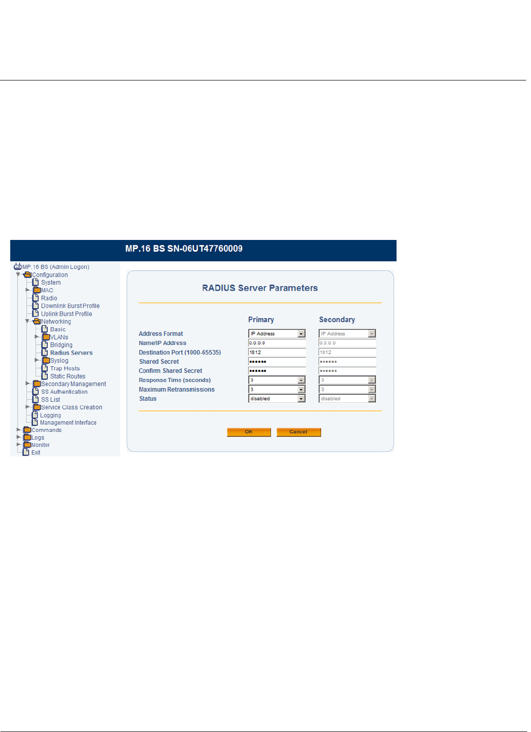
Base Station Configuration Tsunami MP.16 3650 System User Guide
Networking Configuration
57
2. Set the VLAN Priority: Priority to be given to the VLAN Management ID; select a number between 0 and 7.
3. Select a VLAN Management ID. This is one VLAN ID from the VLAN ID List that serves as the Management ID. Only
VLAN packets tagged with this ID will have management access to the BS.
CAUTION: VLAN Management ID must be set when the VLAN mode is set to Trunk.
4. Set Repeating Mode to Enable or Disable. When enabled, the BS allows traffic to be bridged between SSs.
RADIUS Servers
In large networks with multiple units, you can maintain a list of MAC addresses in a centralized location using a RADIUS
authentication server that grants or denies access. If you use RADIUS authentication, you must specify a primary
RADIUS server and associated parameters. The secondary server is not configurable at this time.
Figure 3-13 RADIUS Server Parameters
The following parameters may be viewed or configured:
•Address Format: The format for the RADIUS server address is IP Address.
•Name/IP Address: Enter the IP address of the RADIUS server.
•Destination Port: Enter the port number which the BS and the server will use to communicate. The range is
1000-65536; by default, RADIUS servers communicate on port 1812.
•Shared Secret: Enter the password (between 1 and 255 character) shared by the RADIUS server and the BS. The
same password must also be configured on the RADIUS server. The default password is public.
•Response Time: Enter the maximum time, in seconds, that the BS should wait for the RADIUS server to respond to a
request. The range is 1-10 seconds; the default is 3 seconds.
•Maximum Retransmissions: Enter the maximum number of times an authentication request may be transmitted.
The range is 0 to 4, the default is 3.
•Status: Select Enable from the drop-down box to enable the RADIUS server, or select Disable to disable the
RADIUS server.

Base Station Configuration Tsunami MP.16 3650 System User Guide
Networking Configuration
58
Syslog
Overview
When Secondary Management is enabled on the SS, the MP.16 supports Syslog functionality. Up to two Syslog servers
can be configured, each offering the following alert levels:
Each Syslog message includes a time-stamp, the severity level, and a brief description of the event. Supported Syslog
messages are as follows:
Syslog Configuration
From the Syslog Configuration page, you can enable or disable Syslog server functionality.
Alert Type Severity Level
Emergency 0
Alert 1
Critical 2
Error 3
Warning 4
Notice 5
Informational 6
Debug 7
Description Severity Additional Information
TFTP upload request failed Alert (1)
TFTP upload request successful Warning (4)
TFTP download request failed Alert (1)
TFTP download request successful Warning (4)
System manually rebooted Alert (1)
System cold/warm start Alert (1) BS Only
Event log reset Warning (4)
Interface up Alert (1) Includes interface number
Interface down Alert (1) Includes interface number
SS link lost Alert (1) BS Only
SS modulation dropped to BPSK ½ Critical (2)
SS RSSI dropped below low threshold Critical (2)
SS RSSI increased above high threshold Critical (2)
GPS not present Alert (1) BS Only
GPS lock lost Alert (1) BS Only
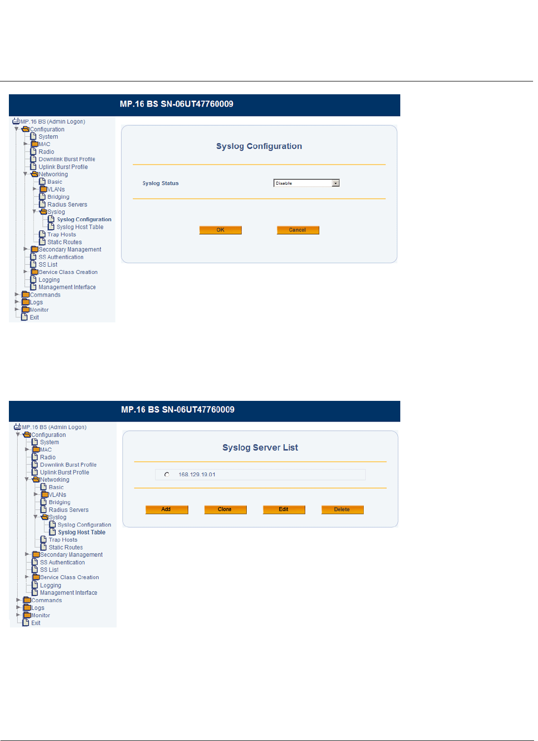
Base Station Configuration Tsunami MP.16 3650 System User Guide
Networking Configuration
59
Figure 3-14 Syslog Configuration
Syslog Host Table
Use the Syslog Host Table page to add and configure the Syslog host(s).
Figure 3-15 Syslog Host Table (Syslog Server List)
1. Do one of the following:
• Click Add to add a new Syslog server to the list. You may add up to two servers.
• Click the radio button next to one of the Syslog server’s IP addresses and click Clone to make a copy of the
Syslog server entry.
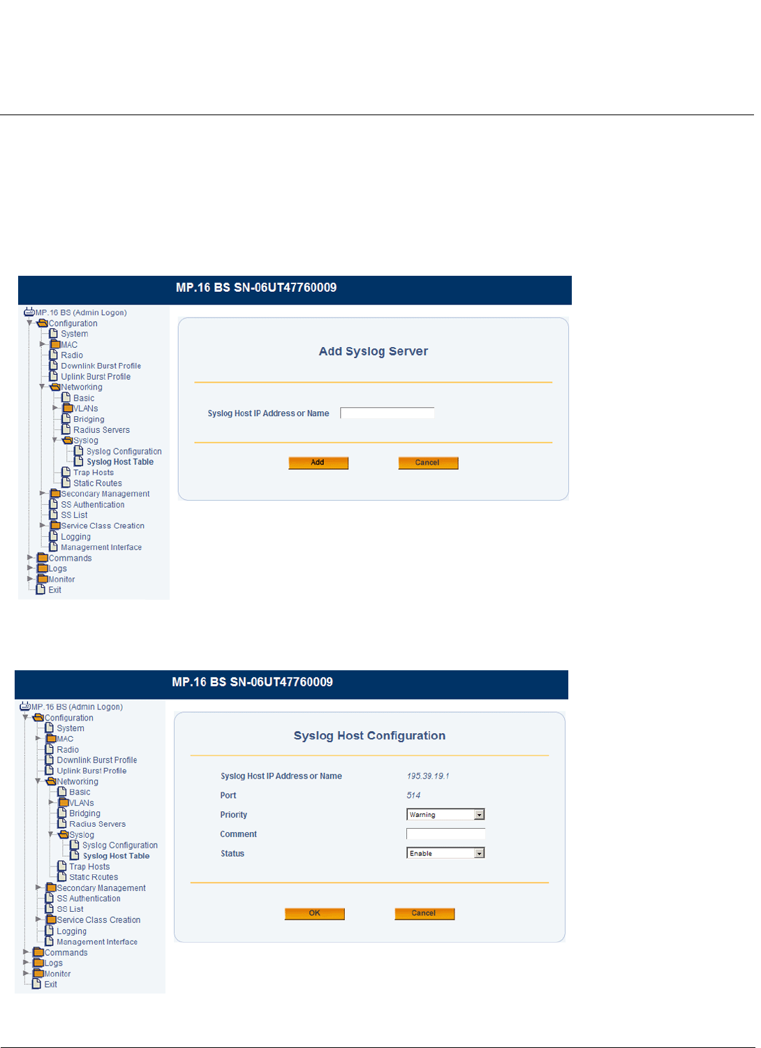
Base Station Configuration Tsunami MP.16 3650 System User Guide
Networking Configuration
60
• Click the radio button next to one of the Syslog server’s IP addresses and click Edit to edit an existing Syslog
server entry.
• Click the radio button next to one of the Syslog server’s IP addresses and click Delete to delete that Syslog server
from the list.
2. If you are adding or cloning a Syslog server entry, specify the IP address of the new server and click Add. If you are
editing an Syslog server entry, you will not be prompted to specify an IP address.
NOTE: When adding a server, you must enter an IP address. Do not enter a name.
Figure 3-16 Adding a Syslog Host
The Syslog Host Configuration page will be displayed.
Figure 3-17 Syslog Host Configuration
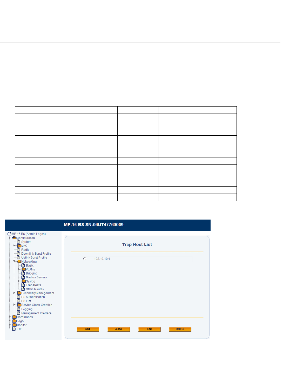
Base Station Configuration Tsunami MP.16 3650 System User Guide
Networking Configuration
61
3. Select the Priority. This selection sets the lowest level alert to be sent to the Syslog server.
4. Enter a Comment. This field is optional.
5. Enable or disable this Syslog server using the Status drop-down menu.
6. Click OK.
Trap Hosts
Traps are sent to the configured list of Trap Hosts. The following traps are supported:
From the Trap Hosts page, you can configure the Trap Hosts.
Figure 3-18 Trap Host List
1. Do one of the following:
• Click Add to add a new Trap host to the list. You may add up to two servers.
• Click the radio button next to one of the Trap host’s IP addresses and click Clone to make a copy of the Trap host
entry.
Description Severity Additional Information
TFTP request failed 1
TFTP request successful 4
System manually rebooted 1
System cold/warm start 1 BS only
Event log reset 4
Interface up 1 Includes interface number
Interface down 1 Includes interface number
SS link lost 1 BS only
SS modulation dropped to BPSK ½ 2 BS only
Service Flow creation 4
GPS not present Alert (1) BS Only
GPS lock lost Alert (1) BS Only
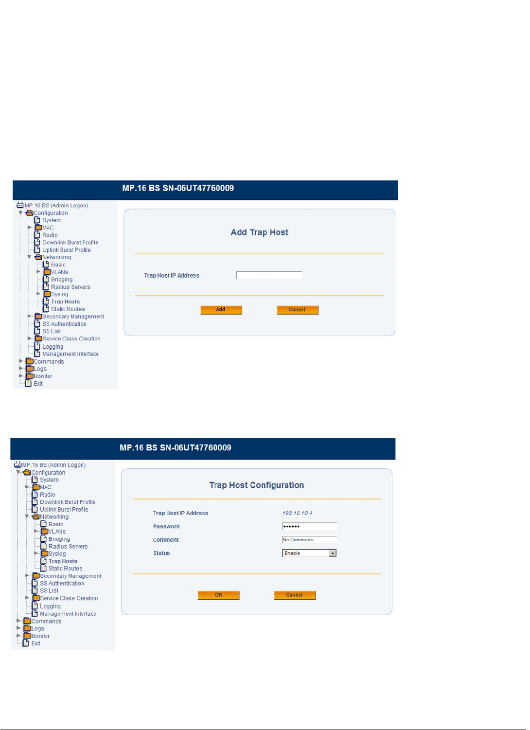
Base Station Configuration Tsunami MP.16 3650 System User Guide
Networking Configuration
62
• Click the radio button next to one of the Trap host’s IP addresses and click Edit to edit an existing Trap host entry.
• Click the radio button next to one of the Trap host’s IP addresses and click Delete to delete that Trap host from the
list.
2. If you are adding or cloning a Trap host entry, specify the IP address of the new host and click Add. If you are editing
an Trap host entry, you will not be prompted to specify an IP address.
NOTE: When adding a host, you must enter an IP address. Do not enter a name.
Figure 3-19 Adding a Trap Host
The Trap Host Configuration page will be displayed.
Figure 3-20 Subscriber Station Configuration
3. Set the Password for the Trap host.
4. Enter a Comment. This field is optional.
5. Enable or disable this Trap host using the Status drop-down menu.
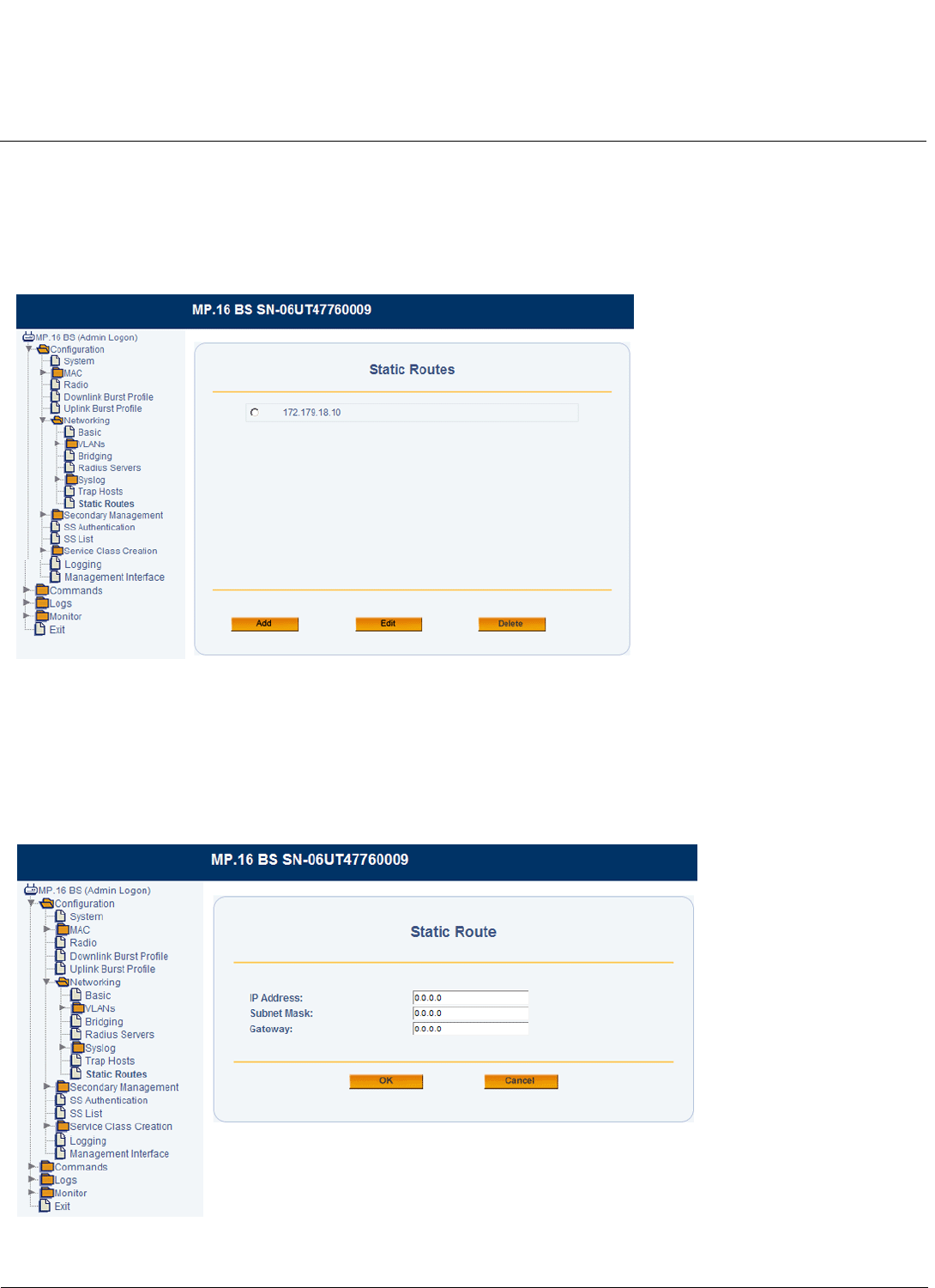
Base Station Configuration Tsunami MP.16 3650 System User Guide
Networking Configuration
63
6. Click OK.
Static Routes
From the Static Routes page, you can configure up to 16 fixed routes from the BS’s Ethernet address to other points on
the network. Each static route consists of destination network, subnet mask, and a gateway address.
Figure 3-21 Static Routes List
1. Do one of the following:
• Click Add to add a Static Route to the list.
• Click the radio button next to one of the routes and click Edit to edit an existing Static Route.
• Click the radio button next to one of the routes and click Delete to delete that route.
If you are adding or editing a Static Route, the Static Route page will be displayed.
Figure 3-22 Static Route Configuration

Base Station Configuration Tsunami MP.16 3650 System User Guide
Networking Configuration
64
2. Enter the following information:
•IP Address: The destination IP address.
•Subnet Mask: Subnet mask of the destination.
•Gateway Address: Default gateway address of the destination.
3. Click OK.

Base Station Configuration Tsunami MP.16 3650 System User Guide
Global Positioning System (GPS)
65
Global Positioning System (GPS)
The Base Station can be configured (via advanced MAC configuration) to enable GPS. In this mode, the BS will require a
functioning GPS recevier to be connected to its GPS/SYNC port. Once the BS attains synchronization with the one pps
signal of the GPS recevier, it will detect any timing delta between the GPS one PPS signal ad its internal start of transmit
frame time. Accordingly, the BS start of transit frame will be adjusted to match the one pps signal of the GPS recevier.
Whenever GPS is enabled and there is synchronization between its one pps signal and the BS, the BS will mute its radio
transmission until such synchronization is attained.
GPS Synchronization
CAUTION: DO NOT enable GPS Synchronization on a Base Station unless you are concurrently connecting a GPS unit
to the Base Station. With GPS enabled, if a GPS unit is not connected to the Base Station, or if the GPS unit
loses satellite reception, the Base Station’s transmittor will shut down until GPS satellite reception is
restored.
GPS Synchronization is enabled on the Tsunami MP.16-3650 Base Station via the Advanced MAC Configuration screen.
After selecting “Enable” from the GPS ENable/Disable menu, click the “OK” button. To complete the process, the Base
Station must be rebooted.
GPS Unit Installation
Position the GPS unit in a location where the antenna plate is parallel to the Earth/horizon. The GPS’domed antenna
should be exposed to as much of the sky possible (clear line-of-sight) so that the GPS unit can always acquire at least
four GPS satellites to extract timing signals for the Base Station transmission synchronization.
Insert the band clamp through the slots in the GPS unit mounting bracket and around the mounting pole. Tighten the
clamp around the mounting pole and then tighten the screw in the clamp to secure the GPS unit mounting bracket to the
mounting pole.
Attach the GPS unit mounting bracket using the #10-32x3/8 SEm screws (the screws with attached washers).
Connecting the GPS Unit to the Base Station
Remove the weather-protection cap from the Base Station’s GPS/SYNC connection enclosure to expose the RJ45 jack.
Plug the GPS unit’s connection cable (RJ45 plug) into the RJ45 jack of the Base Station.
NOTE: When power is applied to the Base Station, the GPS unit automatically be powered as well.
Secure the GPS connection cable assembly as follows:
1. Apply two wraps of Teflon tape around the threads of the Base Station’s GPS/SYNC RJ45 jack enclosure in a
clockwise direction.
2. Make sure that the rubber gasket is properly seated in the sealing cap of the sealing cap/lock nut assembly.
3. Slide the sealing cap/lock nut assembly over the RJ45 jack and thread onto the enclosure. Hand-tighten first, then
use an adjustable wrench or similar tool to tighten one more quarter turn.
4. Tighten the lock nut (Torque 4 N.m/35in-Ibs).
5. Thread the sealing nut onto the sealing cap/lock nut assembly must be fully tightened over the RJ45 connector
before the sealing nut is fully tightened. If not fully tightened first, the GPS unit connection cable may twist and be
damaged.
CAUTION: The lock nut on the sealing cap/lock nut assembly must be fully tightened over the RJ45 connector before
the sealing nut is fully tightened. If not fully tightened first, the GPS unit connection cable may twist and be
damaged.
Waterproof of the GPS connector assembly in the same manner as for the Power/Ethernet connector assembly.
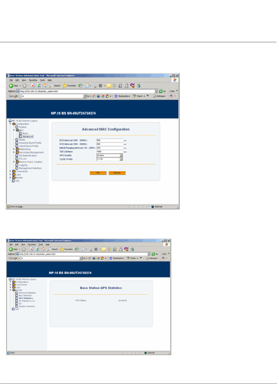
Base Station Configuration Tsunami MP.16 3650 System User Guide
Global Positioning System (GPS)
66
Verifying Base Station GPS Synchronization
Via the Base Station’s web interface, GPS synchronization status can be obversedvia the Base Station GPS Statistics
monitor page.
Figure 3-23 Advenced MAC Configuration
When GPS is disabled on the Base Station, the Base Station will show “disabled”:
Figure 3-24 BSU GPS “disabled” mode
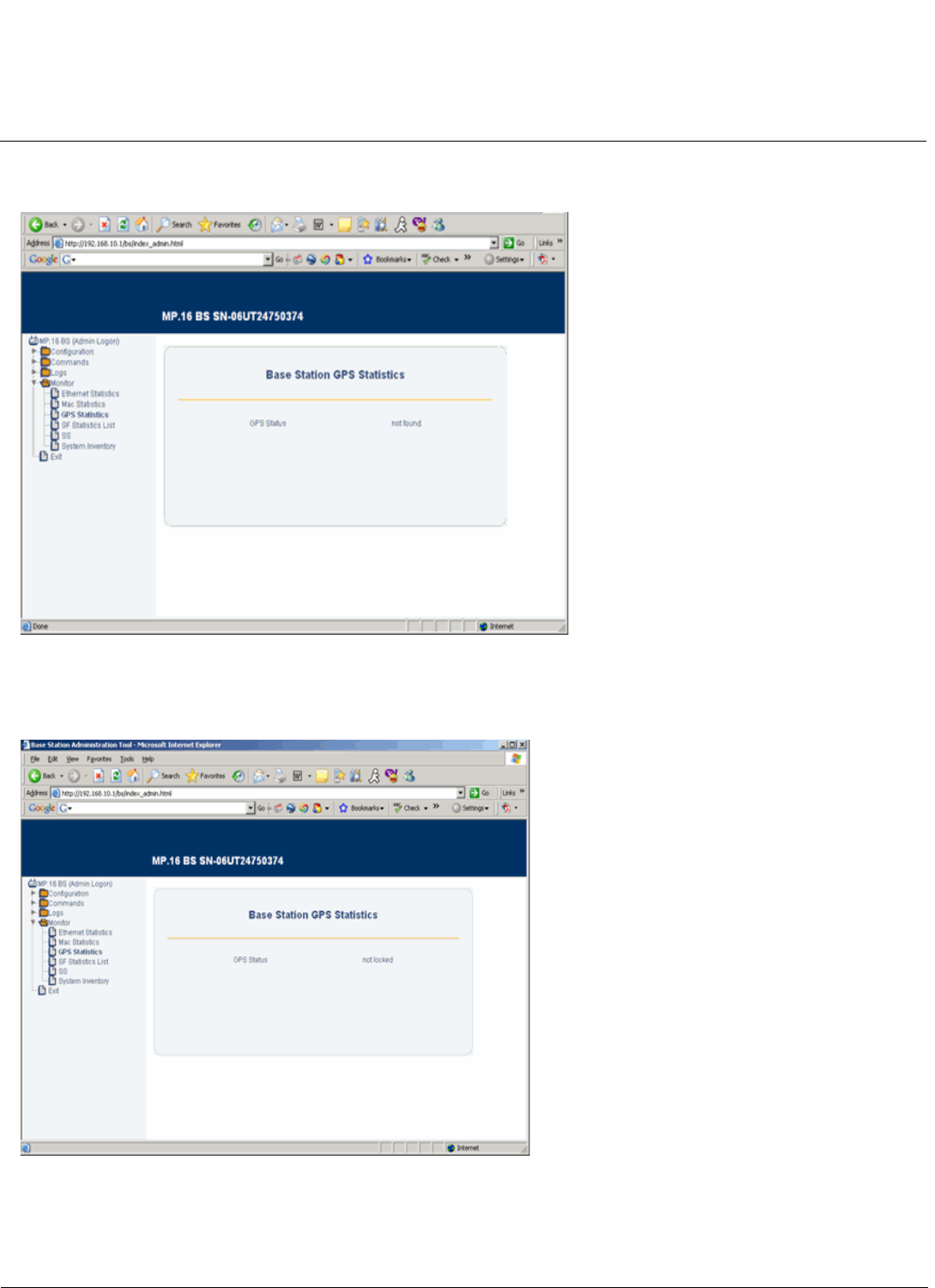
Base Station Configuration Tsunami MP.16 3650 System User Guide
Global Positioning System (GPS)
67
When GPS is enabled on the Base Station, and the GPS recevier is either not connected or is still searching for satellites,
the Base Station will show “not found’:
Figure 3-25 BSU GPS “not found” mode
When the GPS has acquired the satellite signals, but the Base Station has not yet synchronized its internal timing, the
Base Station will show “not locked”:
Figure 3-26 BSU GPS “not locked” mode
When the GPS receiver has processed the GPS timing signal and the Base Station is properly synchronized, the base
Station will show “locked”:
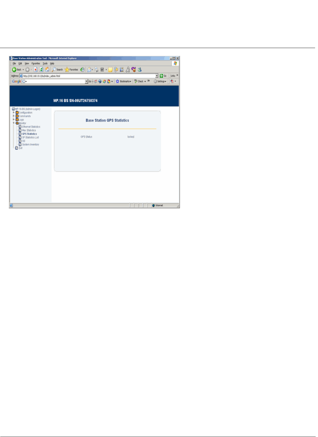
Base Station Configuration Tsunami MP.16 3650 System User Guide
Global Positioning System (GPS)
68
Figure 3-27 BSU GPS “Locked” mode
Cable Assembly for GPS Unit
NOTE: This document provides the pinout and cable assembly for the GPS receiver only for reference purposes. The
GPS kit can be ordered from Proxim and is provided with the assembly/components, as stated in this document.
Secondary Management
Secondary Management allows a Subscriber Station to acquire a set of network settings including IP address and, if
necessary, to download a new configuration file.
When secondary management is enabled on the SS, the SS sends a DHCP request to BS, which is functioning as a
DHCP server. The SS then configures itself based on the DHCP response received. The DCHP response includes:
• The IP address to be used by the SS
• The subnet mask to be used by the SS
• The IP address of the TFTP server that will be used to download a new software image file, if necessary
• The name of the SS software image file to be read from the TFTP server, if necessary
• A list of addresses of one or more routers to be used for forwarding SS-originated IP traffic. The SS uses the first
router in this list as the Default Gateway for all its own IP traffic. It adds others (if present) to the IP Route Table.
• A list of Syslog servers to which logging information may be sent
• A list of time servers from which the current time may be obtained
• The time offset of the SS from UTC. This is used by the SS to calculate the local time for use in time-stamping error
logs.
After the SS has successfully received a valid DHCP response from the BS, the TFTP client allows the Subscriber Station
to download a specified software image file from a specified TFTP Server location. The TFTP Server IP address and the
File Name are retrieved from the DHCP Response.
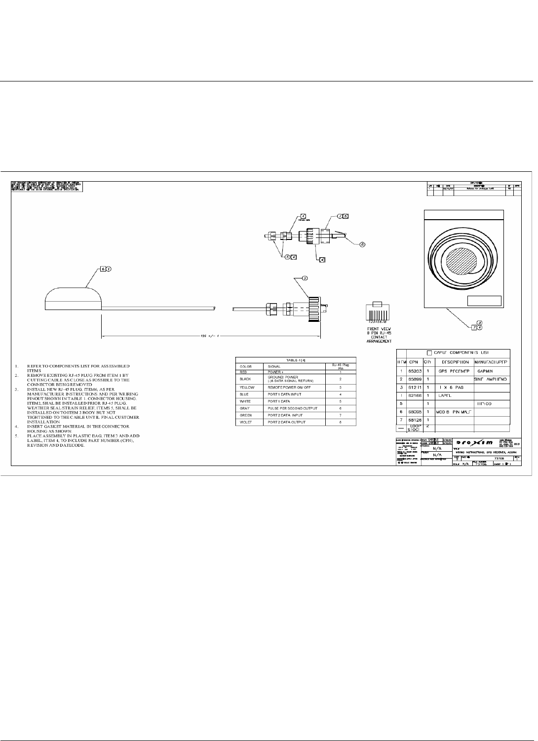
Base Station Configuration Tsunami MP.16 3650 System User Guide
Global Positioning System (GPS)
69
Secondary management is enabled/disabled on the SS (see Network Configuration in the Subscriber Station
Configuration chapter).
TFTP and DHCP settings are configured on the BS. See the following sections:
•TFTP Table
•DHCP Server
TFTP Table
Use the TFTP Table page to configure the parameters used to provide a software image file to the SS (when necessary)
when secondary management is enabled. Entries in the TFTP Secondary Management List Table are based on SS
hardware versions in your network.
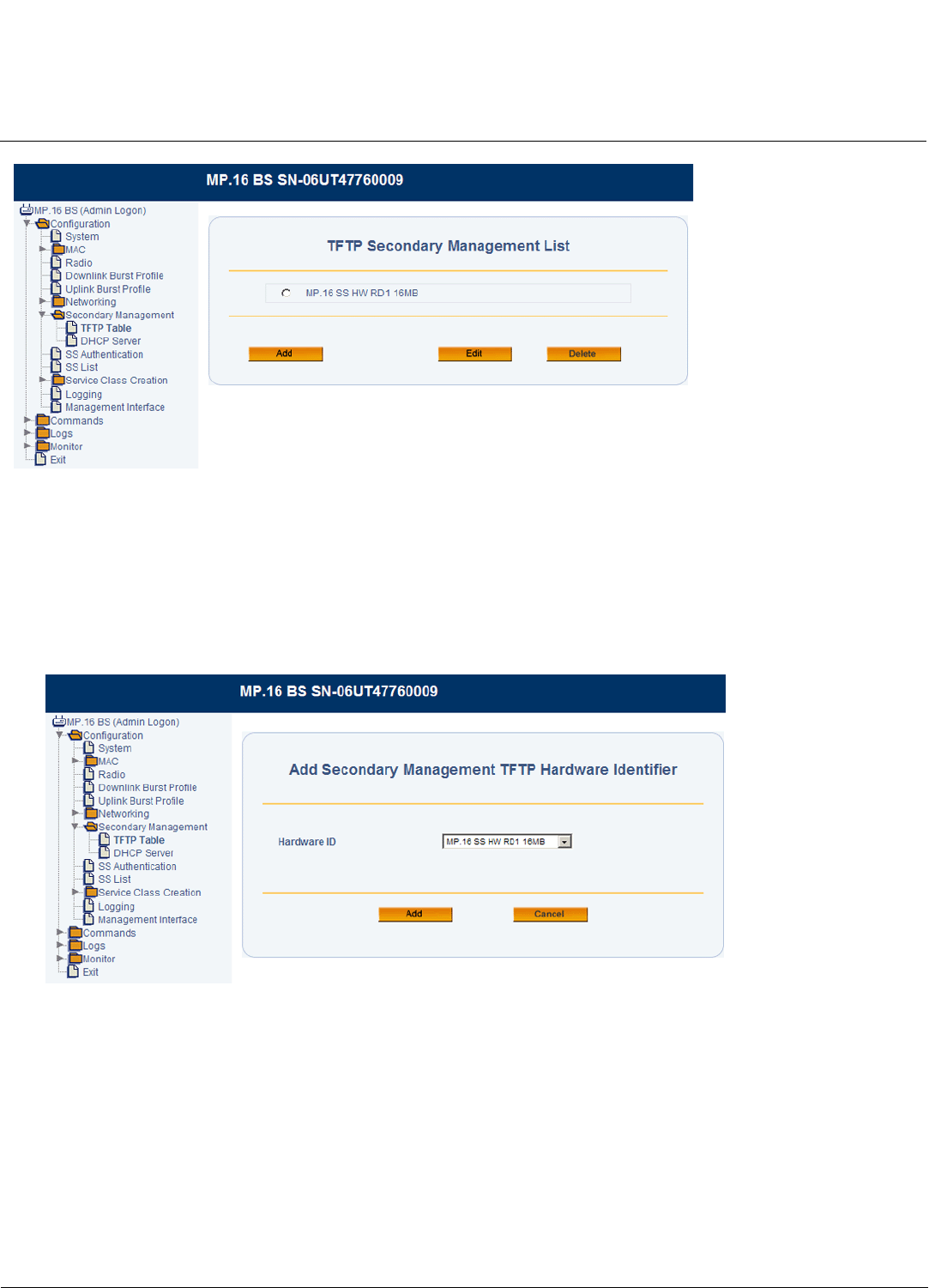
Base Station Configuration Tsunami MP.16 3650 System User Guide
Global Positioning System (GPS)
70
Figure 3-28 TFTP Table
1. Do one of the following
• To add TFTP settings for a new hardware version, click Add.
• To edit TFTP settings for an existing hardware version, select the radio button next to the version you wish to
modify, and click Edit.
2. If you are adding a hardware version, you will be prompted to select the hardware version from a drop-down menu.
Then click Add. If you are editing an existing hardware version, you will not need to select a version.
Figure 3-29 Adding Hardware Identifier
The Secondary Management TFTP Configuration page will be displayed.
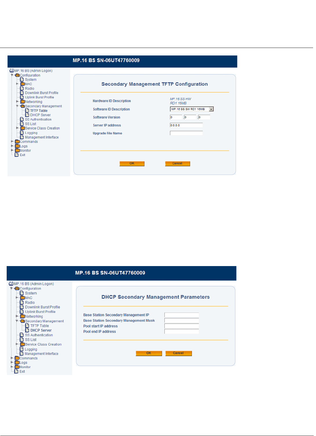
Base Station Configuration Tsunami MP.16 3650 System User Guide
Global Positioning System (GPS)
71
Figure 3-30 Secondary Management TFTP Configuration
3. Enter the Software Version number of the image to be used with the selected hardware.
4. Enter the IP address of the TFTP Server from which the specified software image is available for download.
5. Enter the Upgrade File Name of the software image to be downloaded.
6. Click OK.
DHCP Server
Use the DHCP Server page to configure and enable the BS to function as a DHCP server when secondary management
is enabled on the SS.
Figure 3-31
1. Enter the following information:
•Base Station Secondary Management IP: The IP address of the BS to be used when functioning as a DHCP
server.
•Base Station Secondary Management Mask: The mask of the BS to be used when functioning as a DHCP
server.

Base Station Configuration Tsunami MP.16 3650 System User Guide
Global Positioning System (GPS)
72
•Pool Start IP Address: The first IP address in the DHCP pool.
•Pool End IP Address: The last IP address in the DHCP pool.
2. Click OK.
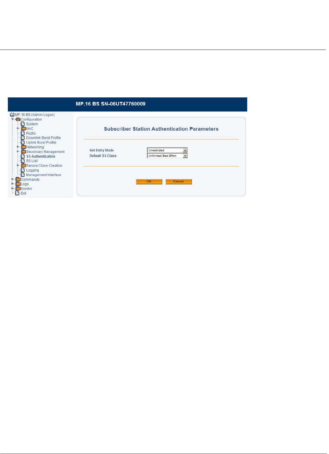
Base Station Configuration Tsunami MP.16 3650 System User Guide
Subscriber Station Authentication
73
Subscriber Station Authentication
Subscriber Station Authentication Parameters determine the authentication method for SSs entering the BS’s network,
and specify a default Subscriber Station class used for any SS entering the network without an otherwise predefined
class.
Figure 3-32 Subscriber Station Authentication Parameters
The following parameters can be configured or viewed from the Subscriber Station Authentication page:
•Net Entry Mode: Select one of the following:
– Unrestricted: All Subscriber Stations may enter the network. This is the default selection.
NOTE: Unrestricted access is intended to simplify initialization and configuration, but as it is not secure, it is not
recommended for a secure deployment.
– Internally Authorized: Only Subscriber Stations listed in the Base Station’s list of authorized SSs can enter the
network. See Subscriber Station List.
– Externally Authorized: Only Subscriber Stations listed in the configured RADIUS server’s list of authorized SSs
can enter the network. When changing to external authorization from any other authorization type, SSs currently
in the SS List must be manually deleted.
•Default SS Class: When the Net Entry mode is set to “Unrestricted,” select the default SS class assigned to all SSs
entering the network without a preassigned SS class. The default is “Unlimited Best Effort.” See Subscriber Station
List for information on assigning non-default SS Classes from a list of pre-defined SS classes and Service Class
Creation for information on creating new classes.
NOTE: When the Net Entry mode is set to “Internally Authorized,” the SS Class is assigned when the SS is added to
the Subscriber Station List. When the Net Entry mode is set to “Externally Authorized,” the SS class is
assigned by the configured RADIUS server.
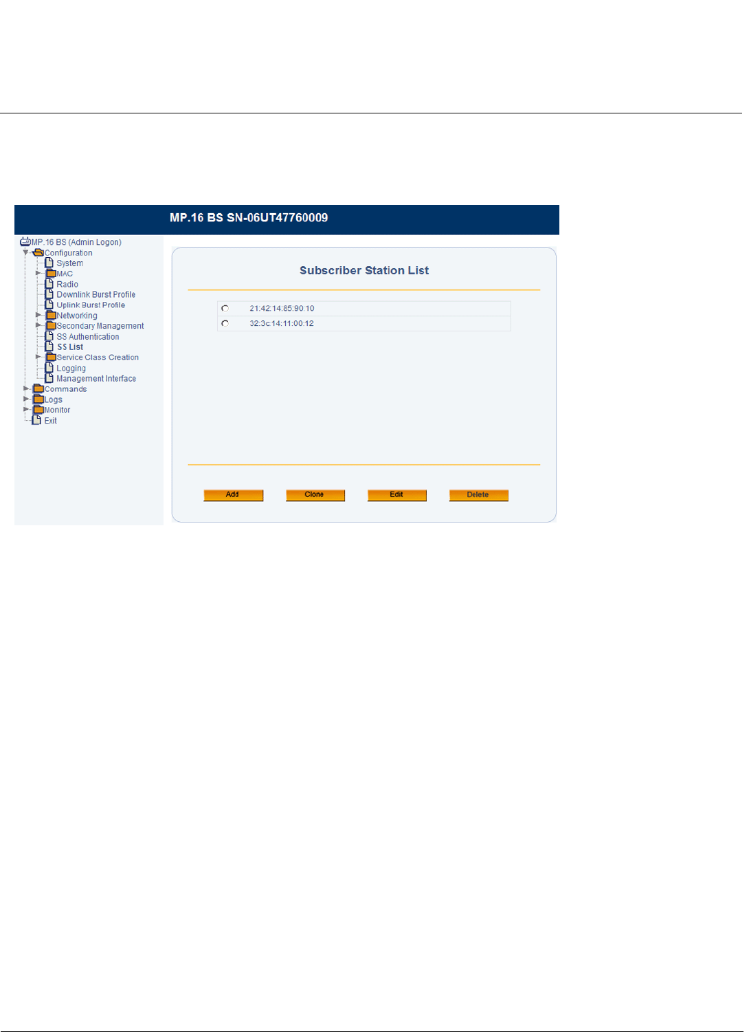
Base Station Configuration Tsunami MP.16 3650 System User Guide
Subscriber Station List
74
Subscriber Station List
From the Subscriber Station List page, you can add SSs to your network, associate them with an SS Class, and
configure select SS-specific parameters.
Figure 3-33 Subscriber Station List
All SSs in the Subscriber Station List are authorized to join the network. Depending on the Net Entry mode of the Base
Station, this list is populated as follows:
• Unrestricted mode: SSs are automatically added to the Subscriber Station List upon registering with the network. The
default SS Class configured on the Subscriber Station Authentication page is initially assigned to SSs.
• Internal authorization mode: Each SS must be manually added to the Subscriber Station List. An SS class is assigned
manually during this process.
CAUTION: In internal authorization mode, only SSs in the Subscriber Station List are authorized to join the network.
• External authorization mode: SSs are added to the Subscriber Station List automatically by the configured RADIUS
server. The RADIUS server assigns an SS class.
CAUTION: When changing to external authorization from any other authorization type, SSs currently in the SS List
must be manually deleted.
The administrator may optionally configure parameters of individual SSs on the list, including assigning an SS class,
overriding particular elements of an assigned SS Class, and resetting overridden parameters to their default states.
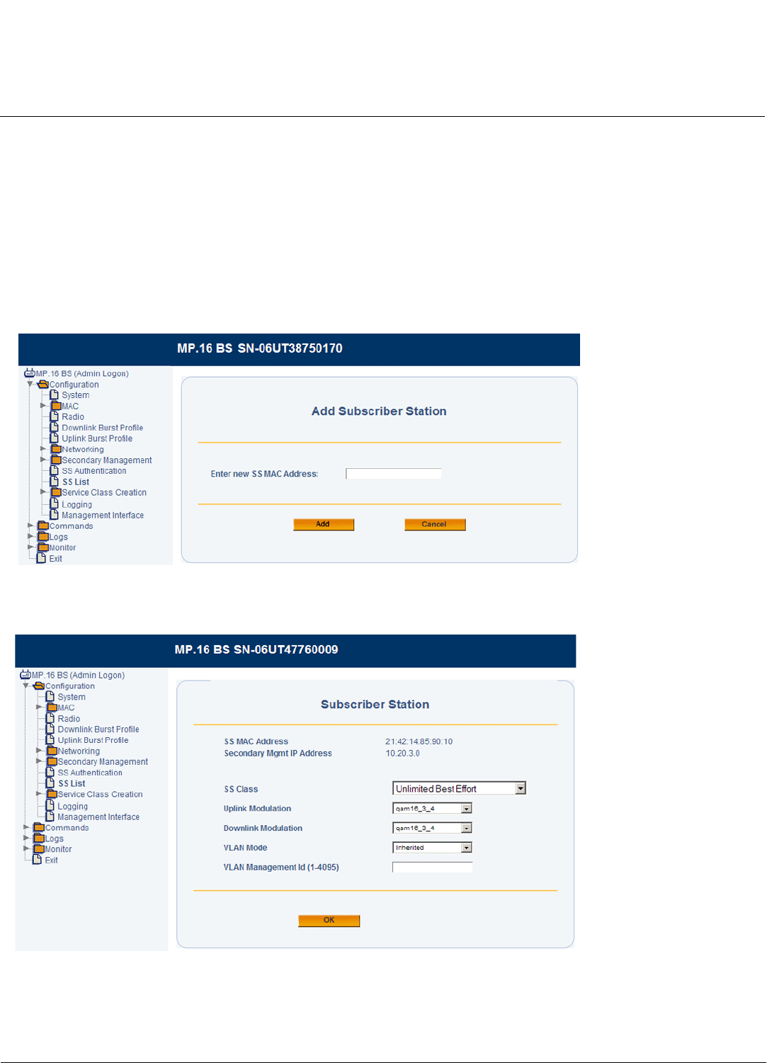
Base Station Configuration Tsunami MP.16 3650 System User Guide
Subscriber Station List
75
Subscriber Station List Configuration
NOTE: You must reboot the SS for any configuration changes to take effect.
1. Do one of the following:
• Click Add to add an authorized SS to the list.
• Click the radio button next to one of the SS MAC addresses and click Clone to make a copy of SS entry.
• Click the radio button next to one of the SS MAC addresses and click Edit to edit an existing SS entry.
• Click the radio button next to one of the SS MAC addresses and click Delete to delete that SS from the list.
2. If you are adding or cloning an SS entry, specify the MAC address of the new SS and click Add. If you are editing an
SS entry, you will not be prompted to specify a MAC address.
Figure 3-34 Adding a Subscriber Station
The Subscriber Station page will be displayed.
Figure 3-35 Subscriber Station Configuration
3. Select an SS Class. The drop-down menu displays the currently assigned SS Class. Use the drop-down menu to
select a different SS Class. If a desired class of service is not contained in this list, you may create it (see Service
Class Creation) and then return to the Subscriber Station List page to assign it to one or more SSs.

Base Station Configuration Tsunami MP.16 3650 System User Guide
Subscriber Station List
76
4. Specify an Uplink Modulation for the SS. When adaptive is selected, the SS will continually monitor and adjust to
select the best modulation for the link conditions.
5. Specify an Downlink Modulation for the SS. When adaptive is selected, the SS will continually monitor and adjust to
select the best modulation for the link conditions.
6. Set the VLAN parameters of the SS:
• To use the VLAN parameters associated with the assigned SS Class, select Inherited from the VLAN Mode
drop-down menu, and click OK. The VLAN Management ID configured with the SS Class will be used; this field is
not configurable here.
• To override the VLAN parameters associated with the assigned SS Class, select Transparent, Access, Trunk, or
Mixed from the drop-down menu. and configure parameters as described in the following sections:
– To set the VLAN mode to Transparent, see Configuring an Individual SS for Transparent Mode (Override)
– To set the VLAN mode to Access, see Configuring an Individual SS for Access Mode (Override)
– To set the VLAN mode to Trunk, see Configuring an Individual SS for Trunk Mode (Override)
– To set the VLAN mode to Mixed, see Configuring an Individual SS for Trunk Mode (Override)
–
NOTE: To reset an override to the value specified by the SS Class, set VLAN Mode to Inherited.
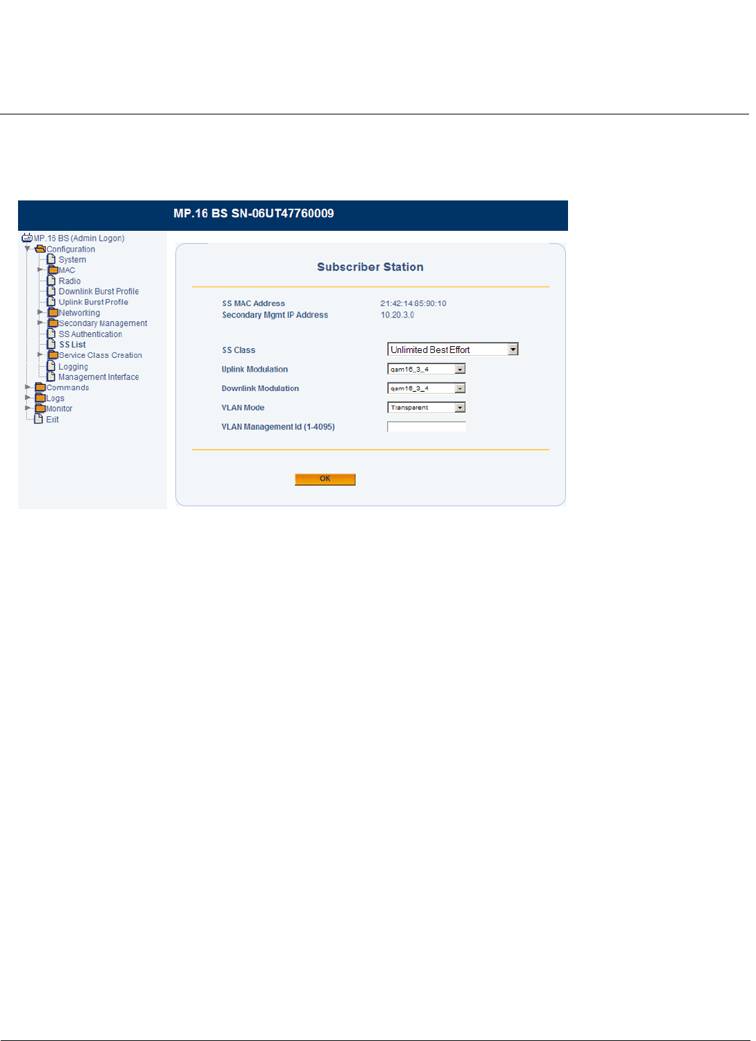
Base Station Configuration Tsunami MP.16 3650 System User Guide
Subscriber Station List
77
Configuring an Individual SS for Transparent Mode (Override)
If the BS’s VLAN mode is set to Transparent, the SS’s VLAN mode may be set to Transparent. With the SS’s VLAN mode
set to Transparent, the following screen will be displayed:
Figure 3-36 SS VLAN Configuration Override (Transparent Mode)
In Transparent mode, all tagged and untagged packets can access the device. There is therefore no need to specify a
VLAN Management ID; this field is not configurable.
Once the VLAN Mode is set, click OK.
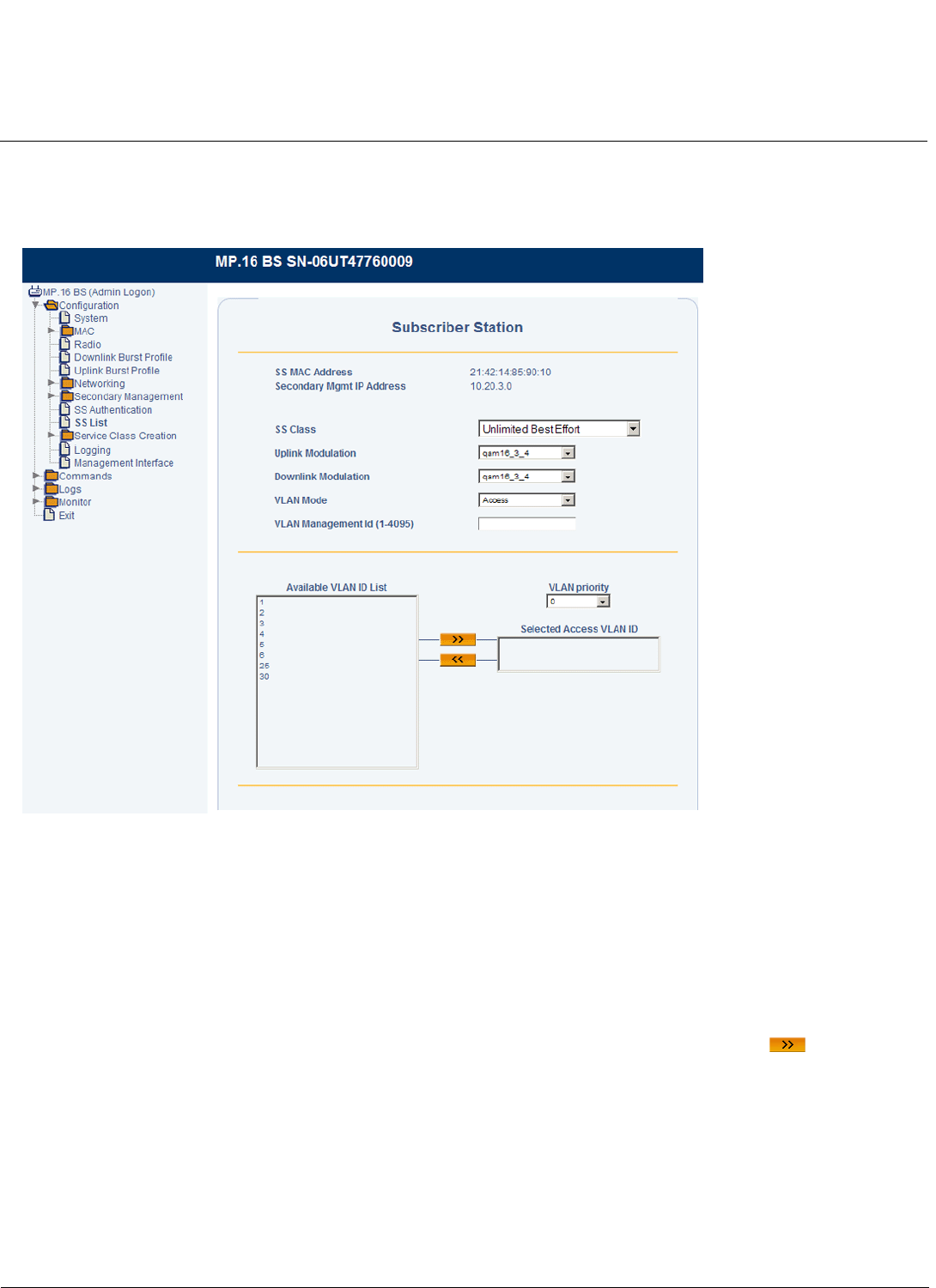
Base Station Configuration Tsunami MP.16 3650 System User Guide
Subscriber Station List
78
Configuring an Individual SS for Access Mode (Override)
If the BS’s VLAN mode is set to Transparent or Trunk, the SS’s VLAN mode may be set to Access. With the SS’s VLAN
mode set to Access, the following screen will be displayed:
Figure 3-37 SS VLAN Configuration Override (Access Mode)
In Access mode, only one VLAN ID may be specified as having access to the SS. This VLAN ID has management
access.
NOTE: When you move the VLAN ID to the Selected Access VLAN ID list, the VLAN Management ID field will be
automatically populated with this ID.
Set the following parameters and then click Save & Finish:
•Selected VLAN Access ID: Select one VLAN ID from the Available VLAN ID List to serve as the Management ID.
Only VLAN packets tagged with this ID will have access to and be able to manage the SS. To designate a VLAN ID as
the Management ID, select the VLAN ID from Available VLAN ID List, and click the right arrow . To designate a
different VLAN ID as the Management ID, remove the current VLAN ID by clicking the left arrow, and select a different
VLAN ID from the list.
•VLAN Priority: Priority to be given to the Selected Access VLAN ID; select a number between 0 and 7.
For information on configuring the Available VLAN ID List, see VLAN ID List.
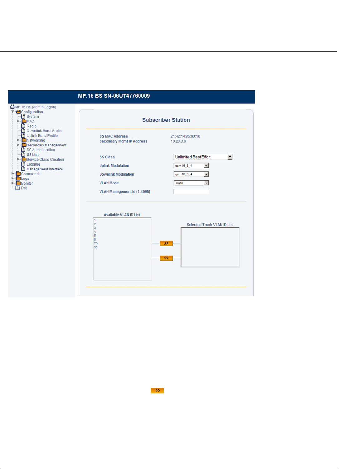
Base Station Configuration Tsunami MP.16 3650 System User Guide
Subscriber Station List
79
Configuring an Individual SS for Trunk Mode (Override)
If the BS’s VLAN mode is set to Trunk, the SS’s VLAN mode may be set to Trunk. With the SS’s VLAN mode set to Trunk,
the following screen will be displayed:
Figure 3-38 SS VLAN Configuration Override (Trunk Mode)
In Trunk mode, up to 16 VLAN IDs may be specified as having access to the SS. Additionally, one of these VLAN IDs
must be designated as the VLAN Management ID for the VLAN.
NOTE: The total number of VLANs and Service Flows must not exceed 20.
Set the following parameters and click OK:
•VLAN Management ID: Select one VLAN ID from the Selected Trunk VLAN ID List to serve as the Management ID.
Only VLAN packets tagged with this ID will have management access to the SS. If the VLAN ID entered in this field is
not contained in the Selected Trunk VLAN ID List, an error message will be displayed when you click OK.
•Selected VLAN ID List: You may add up to 16 VLAN IDs to this list. To add a VLAN ID, select the VLAN ID from
Available VLAN ID List, and click the right arrow . To remove a VLAN ID from the list, select the ID and click the
left arrow.
NOTE: After clicking OK, the selected Management ID will be automatically moved to the top of the Selected Trunk
VLAN ID List.
For information on configuring the Available VLAN ID List, see VLAN ID List.
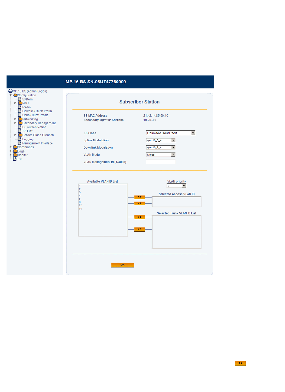
Base Station Configuration Tsunami MP.16 3650 System User Guide
Subscriber Station List
80
Configuring an Individual SS for Mixed Mode (Override)
If the BS’s VLAN mode is set to Trunk, the SS’s VLAN mode may be set to Mixed. With the SS’s VLAN mode set to
Trunk, the following screen will be displayed:
Figure 3-39 SS VLAN Configuration Override (Mixed Mode)
In Mixed mode, one VLAN Access ID and up to 16 VLAN Trunk IDs may be specified as having access to the SS. The
VLAN Access ID has management access.
NOTE: When you move a VLAN ID to the Selected Access VLAN ID list, the VLAN Management ID field will be
automatically populated with this ID.
NOTE: The total number of VLANs and Service Flows must not exceed 20. When using Mixed mode, this number
includes the Access VLAN ID as well as the Trunk VLAN IDs.
Set the following parameters and click OK:
•Selected Access VLAN ID: Select one VLAN ID from the Available VLAN ID List to serve as the Access VLAN ID.
Only VLAN packets tagged with this ID will have access to and be able to manage the SS. To designate a VLAN ID as
the Access VLAN ID, select the VLAN ID from Available VLAN ID List, and click the right arrow . To designate a
different VLAN ID as the Management ID, remove the current VLAN ID by clicking the left arrow, and select a different
VLAN ID from the list.

Base Station Configuration Tsunami MP.16 3650 System User Guide
Subscriber Station List
81
•VLAN Priority: Priority to be given to the Selected Access VLAN ID; select a number between 0 and 7.
•Selected Trunk VLAN ID List: You may add up to 16 VLAN IDs to this list. To add a VLAN ID, select the VLAN ID
from Available VLAN ID List, and click the right arrow . To remove a VLAN ID from the list, select the ID and click
the left arrow.
For information on configuring the Available VLAN ID List, see VLAN ID List.
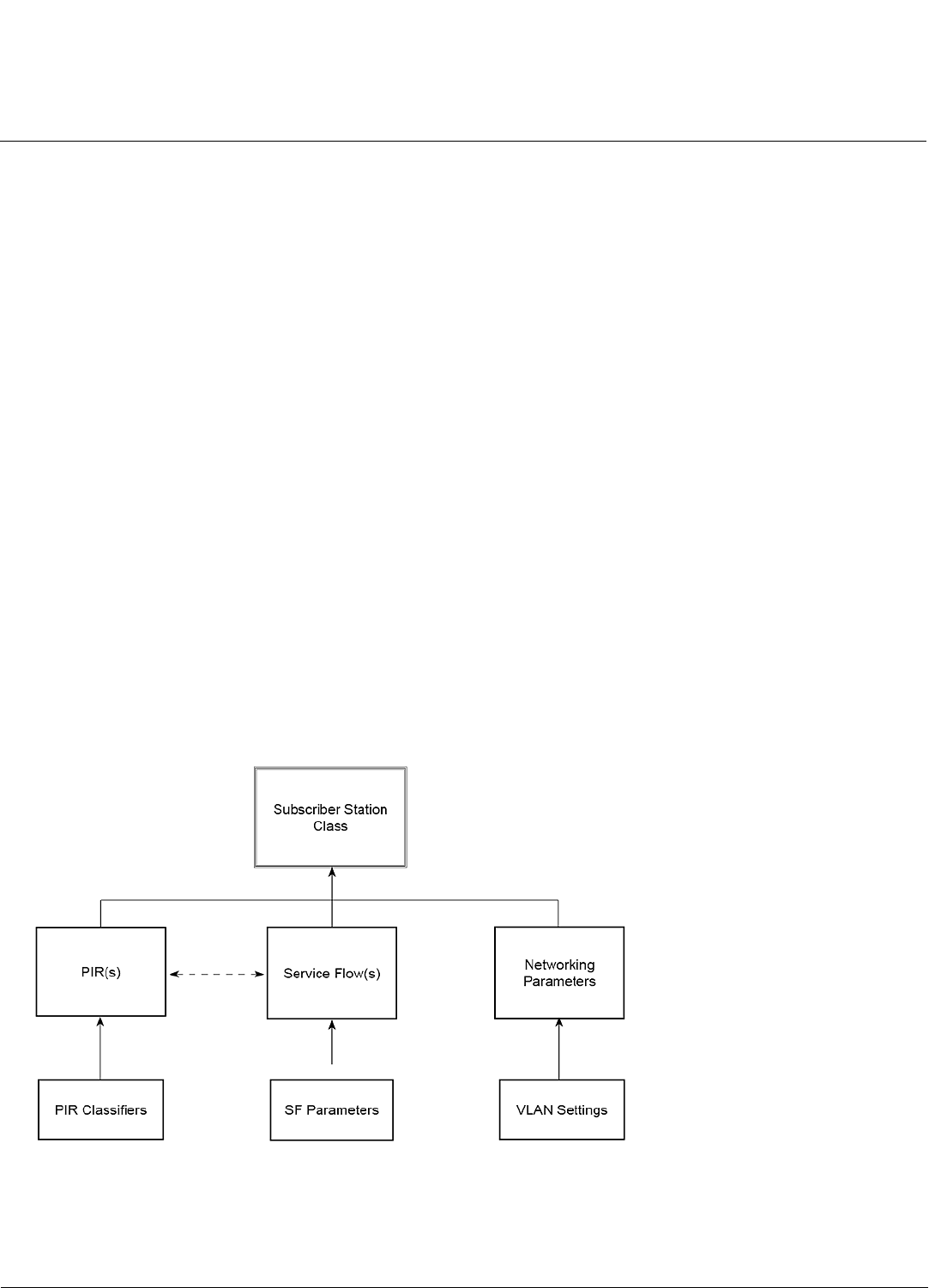
Base Station Configuration Tsunami MP.16 3650 System User Guide
Service Class Creation
82
Service Class Creation
Introduction
When a Subscriber Station enters the network, its MAC address must be added to the network and associated with an SS
class. Upon entering the network, an SS uses either the default SS class configured on the BS (under the Subscriber
Station Authentication tab) or a pre-assigned SS class (assigned by the BS under the Subscriber Station List tab or by the
configured RADIUS server).
The MP.16 system comes with several predefined SS classes; however, the system also allows you to edit these classes
or define custom classes to fit your particular system’s needs. The following sections provide more information on SS
classes and custom SS class creation.
•Subscriber Station Classes: Overview
•Service Class Creation
•PIR Creation
•Service Flow Creation
•Subscriber Station Class Creation
For instructions on assigning a pre-defined class to an SS, see Subscriber Station Authentication (to select a default SS
class for all SSs entering the network when the Net Entry mode is set to “Unrestricted”) and Subscriber Station List (to
assign SS classes to individual SSs when the Net Entry mode is set to “Internally Authorized”).
NOTE: When the Net Entry mode is set to “Externally Authorized,” the SS class is assigned by the configured RADIUS
server.
Subscriber Station Classes: Overview
Figure 3-40 depicts the process of defining custom Subscriber Station classes.
Figure 3-40 Defining SS Classes
The fundamental building blocks of an SS class are:
•PIRs, which determine which packets are mapped to which service flows.

Base Station Configuration Tsunami MP.16 3650 System User Guide
Service Class Creation
83
•Service Flows, including their direction and QoS traffic scheduling mechanism(s)
•Networking Parameters, including VLAN properties.
Packet Identification Rules
PIRs are rules that are matched against fields of incoming packets for the purpose of mapping the packet onto the
appropriate service flow. A PIR includes one or more of eleven different classifier fields, which, if included, are matched
against the incoming packet. If a PIR includes multiple classifiers, every included field must match the incoming packet
for the rule to match. The only parts of the packet that are inspected are those corresponding to classifiers included in the
PIR.
PIRs are extremely flexible and can be used In many different ways. Some examples include:
• Using the ToS field in a classification rule to identify a certain class of differentiated IP traffic. This then could be used
to map from the layer 3 QoS to the underlying 802.16 service flow providing the necessary QoS guarantees.
• Using the destination IP address field to identify uplink traffic destined to a particular server address, such as a VoIP
gateway. This could be used to identify VoIP traffic and map it to the appropriate service flow.
A priority is used when assigning a PIR to a Service Flow during SS Class configuration (as described in Step 2:
Associate PIRs with Service Flows later in this guide). This priority is used to filter traffic, with higher priority PIRs being
serviced first. PIR priority is not used per Service Flow on the BS, so unique PIR priority values across all SS Classes are
required to ensure proper traffic prioritization.
Service Flows
As PIRs determine which traffic gets directed to which Service Flow, the Service Flows, in turn, determine the traffic’s
QoS treatment.
The SF direction specifies whether the service flow is to be used by uplink (to the BS) or downlink (from the BS) traffic.
•An uplink service flow is intended for traffic flowing from an SS to the BS.
•A downlink service flow is intended for traffic flowing from a BS to an SS.
SF Quality of Service (QoS)
The SF’s QoS traffic scheduling settings define the method by which bandwidth is allocated for packets sent over that
service flow.
Quality of Service (QoS) for networks is an industry-wide set of standards and technologies for ensuring high-quality
performance for critical applications. By using QoS mechanisms, network administrators can use existing resources
efficiently and ensure the required level of service without reactively expanding or over-provisioning their networks.
Traditionally, the concept of quality in networks meant that all network traffic was treated equally. The result was that all
network traffic received the network’s best effort, with no guarantees for reliability, delay, variation in delay, or other
performance characteristics. With best-effort delivery service, however, a single bandwidth-intensive application can
result in poor or unacceptable performance for all applications. The QoS concept of quality is one in which the
requirements of some applications and users are more critical than others, which means that some traffic needs
preferential treatment.
The goal of QoS is to provide preferential delivery service for the applications that need it by ensuring sufficient
bandwidth, controlling latency and jitter, and reducing data loss, while also making sure that providing priority for one or
more flows does not make other flows fail.
QoS lets you provide better service to certain flows of traffic. This is done by either raising the priority of a flow or limiting
the priority of another flow. You can raise the priority of a flow by queuing and servicing queues in different ways:
• Raise priority by dropping lower-priority flows before higher-priority flows.
• Police and shape priority to a flow by limiting the throughput of other flows.

Base Station Configuration Tsunami MP.16 3650 System User Guide
Service Class Creation
84
• Limit large flows to show a preference for small flows.
The Tsunami MP.16 system lets complex networks control and predictably service a variety of networks applications and
traffic types. Almost any network can take advantage of QoS for optimum efficiency, whether it is a small corporate
network, an Internet Service Provider, or an enterprise network.
QoS Traffic Scheduling Mechanisms
The MP.16 system supports four types of QoS traffic scheduling mechanisms:
•Unsolicited Grant Services (UGS): UGS is designed to support constant bit rate services like T1/E1 and VoIP
without silence suppression. In the MP.16 system, UGS QoS parameters include maximum sustained data rate,
maximum latency, and tolerable jitter.
•Real-Time Polling Services (rtPS): rtPS is designed to support real-time services that generate variable size data
packets on a periodic basis, such as MPEG video or VoIP with silence suppression. In the MP.16 system, rtPS QoS
parameters include maximum sustained data rate, minimum reserved traffic rate, and maximum latency.
•Non-Real-Time Polling Services (nrtPS): nrtPS is designed to support non-real-time services that require variable
size data grant burst types on a regular basis. In the MP.16 system, nrtPS QoS parameters include maximum
sustained data rate, minimum reserved traffic rate, and traffic priority.
•Best Effort Services: BE services are typically provided by the Internet today for Web surfing. In the MP.16 system,
BE QoS parameters include maximum sustained data rate and traffic priority.
Networking Parameters
SS class networking parameters include VLAN settings. These settings are dependent on the VLAN mode of the Base
Station. See VLANs in the Networking Configuration section for a description of VLAN functionality.
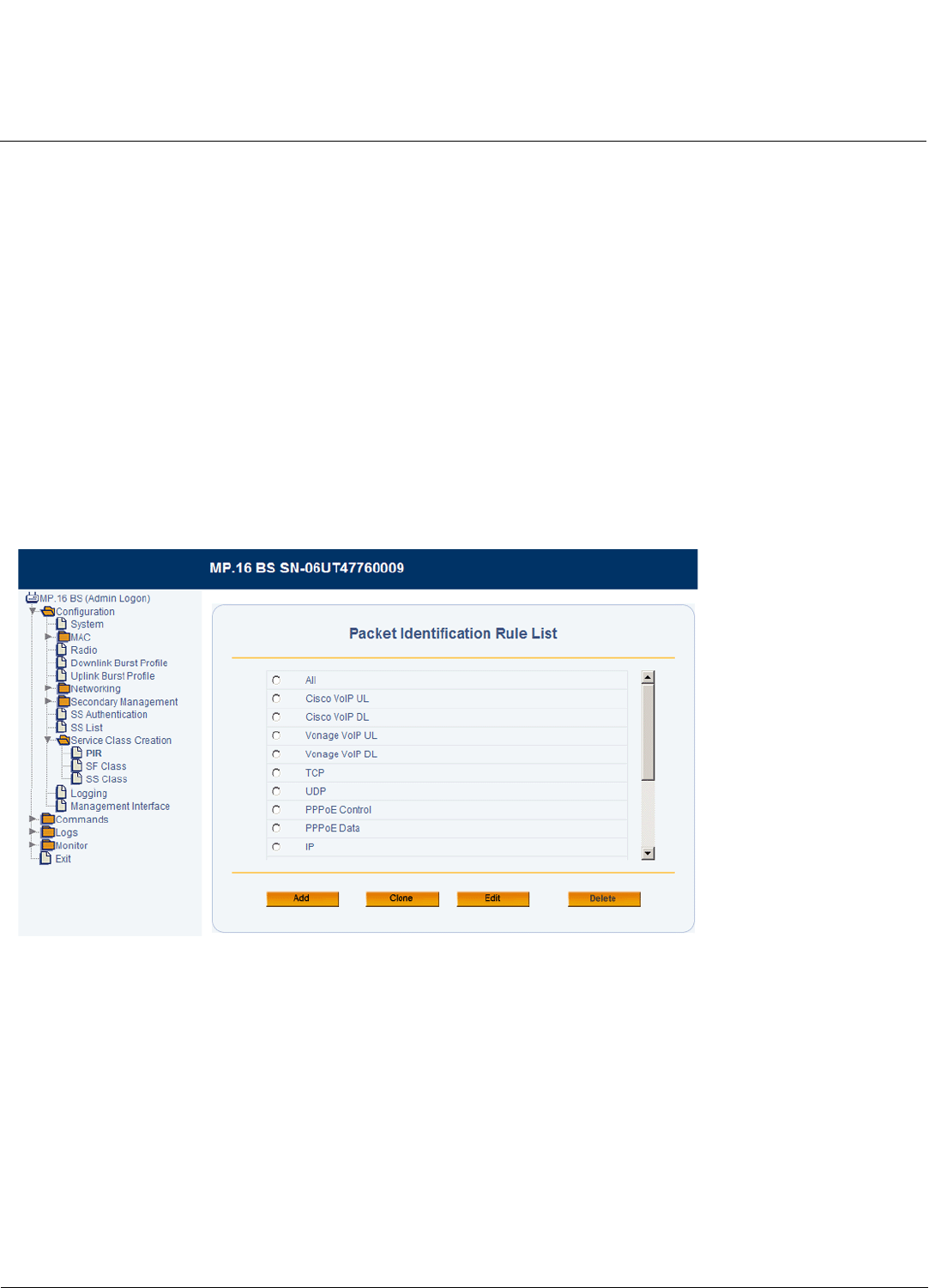
Base Station Configuration Tsunami MP.16 3650 System User Guide
Service Class Creation
85
Service Class Creation
NOTE: You must reboot the SS for any configuration changes to take effect.
The steps for creating SS classes are as follows:
•PIR Creation
•Service Flow Creation
•Subscriber Station Class Creation
–Step 1: Select Service Flows
–Step 2: Associate PIRs with Service Flows
–Step 3: Networking Parameters
PIR Creation
From the Packet Identification Rule List page, you can create, delete, and edit up to 512 PIRs that identify specific traffic
types, including those that are predefined for you (see Pre-Defined PIRs).
1. Click Service Class Creation > PIRs
Figure 3-41 Packet Identification Rule List
2. Do one of the following:
• Click Add to create a new PIR.
• Click the radio button next to one of the PIRs and click Clone to make a copy of that PIR.
• Click the radio button next to one of the PIRs and click Edit to edit an existing PIR.
• Click the radio button next to one of the PIRs and click Delete to delete that PIR from the list.
3. If you are adding or cloning a PIR, specify a unique PIR Name between 1 and 32 characters, and click Add.
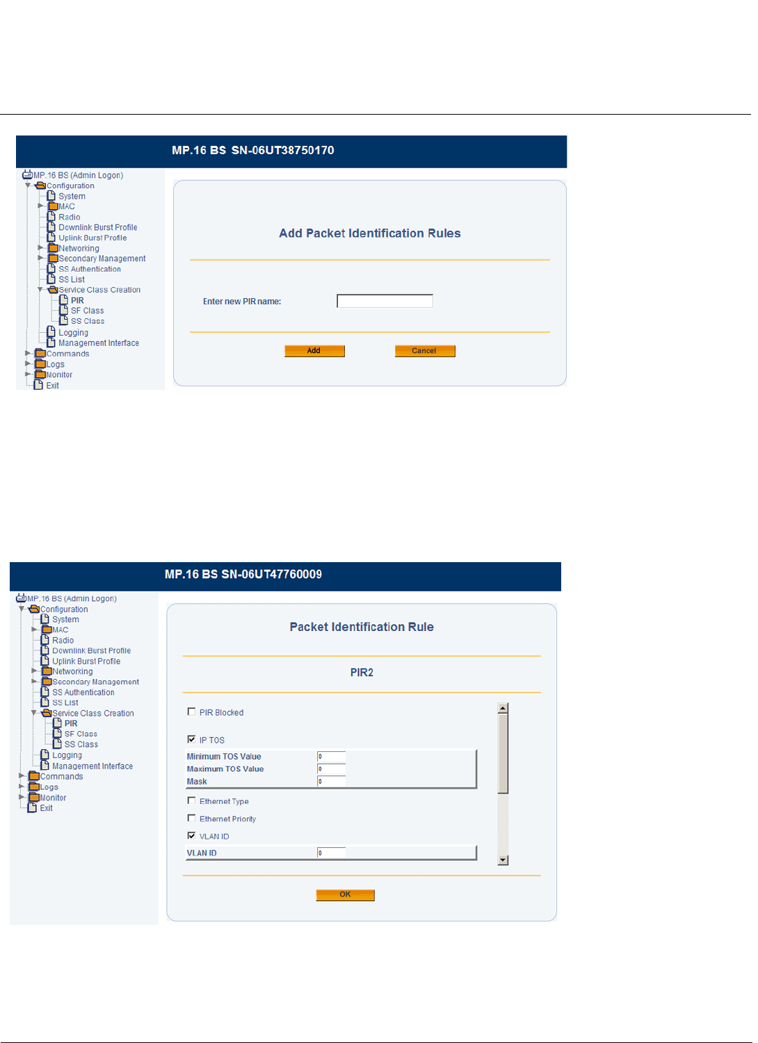
Base Station Configuration Tsunami MP.16 3650 System User Guide
Service Class Creation
86
Figure 3-42 Add Packet Identification Rules Screen
The Configuration screen for the PIR will be displayed.
4. Place a check mark in the box next a classifier name to configure it and add it to the PIR. Uncheck the box to remove
the classifier from the PIR. In the following figure, the IP TOS and VLAN ID classifiers are selected and expanded for
configuration.
NOTE: If you are editing or cloning a PIR, some classifiers will already be expanded and configured; you may modify
these classifiers as needed or uncheck the box to remove them from the PIR.
Figure 3-43 PIR Classifier List
5. If packets matching the classifiers configured below are to be blocked, select the PIR Blocked box. If this box is not
checked, packets matching the classifiers configured below will be allowed.
6. Configure the desired classifiers as follows.

Base Station Configuration Tsunami MP.16 3650 System User Guide
Service Class Creation
87
•IP TOS: To identify a packet by IP Type of Service, specify a minimum TOS value, maximum TOS value, and
mask. The minimum and maximum values must be numeric values between 0 and 255, with the minimum being
equal to or less than the maximum. The mask is a value between 0 and 255.
•Ethernet Type: To identify a packet by Ethernet Type, classify either DIX- or SNAP-encapsulated frames, or
frames with an SAP less than or greater than 0xAA. For DIX- or SNAP-encapsulated frames, specify a 16-bit
Ethernet type. For frames with an SAP less than or greater than 0xAA, specify an 8-bit Ethernet type.
•Ethernet Priority: Specify the minimum and maximum priority in the 802.1Q priority. The range is 0-7.
•VLAN ID: To identify a packet by VLAN ID, specify a VLAN ID.
•Source IP Address: To identify a packet by IP source address, specify a list of 1 to 16 address/mask
combinations.
•Dest IP Address To classify by IP destination address, specify a list of 1 to 16 address/mask combinations.
•Source IP Port Low: To identify a packet by source port range, specify a list of 1 to 16 port ranges. For each
range, the low value must be less than or equal to the high value. Ranges cannot overlap.
NOTE: This field can be defined only if TCP or UDP are included in the IP Protocol list (see IP Protocol List
above).
•Destination IP Port Low: To identify a packet by destination port range, specify a list of 1-16 port ranges. For
each range, values can range between 1-65535, and the low value must be less than or equal to the high value.
Ranges cannot overlap.
NOTE: This field can be defined only if TCP or UDP are included in the IP Protocol list.
•IP Protocol: To identify a packet by IP protocol, specify a list of up to 16 values.
•Source MAC Address: To identify a packet by source MAC address, specify a list of 1 to 16 MAC addresses and
masks. Masks default to FF:FF:FF:FF:FF:FF.
•Destination MAC Address: To identify a packet by destination MAC address, specify a list of 1 to 16 MAC
addresses and masks. Masks default to FF:FF:FF:FF:FF:FF.
7. Click OK.
Pre-Defined PIRs
The MP.16 system comes with several pre-defined PIRs that can be used as is, edited, or used as templates for the
creation of new PIRs. These pre-defined PIRs can be deleted by the administrator; if they are deleted, they are restored
if the system is reset to factory defaults.
The following table describes the pre-defined PIRs:
Table 3-3 Pre-Defined PIRs
PIR Name Classification Fields
All No classification fields; all traffic matches
Cisco VoIP UL Protocol Source Port Range (16,000-33,000)
IP Protocol List (17)
Vonage VoIP UL Protocol Source Port Range (5060-5061, 10000-20000)
IP Protocol List (17)
Cisco VoIP DL Protocol Source Port Range (16,000-33,000)
IP Protocol List (17)
Vonage VoIP DL Protocol Source Port Range (5060-5061, 10000-20000)
IP Protocol List (17)
TCP IP Protocol List (6)
UDP IP Protocol List (17)
PPPoE Control Ethertype (type 1, 0x8863)
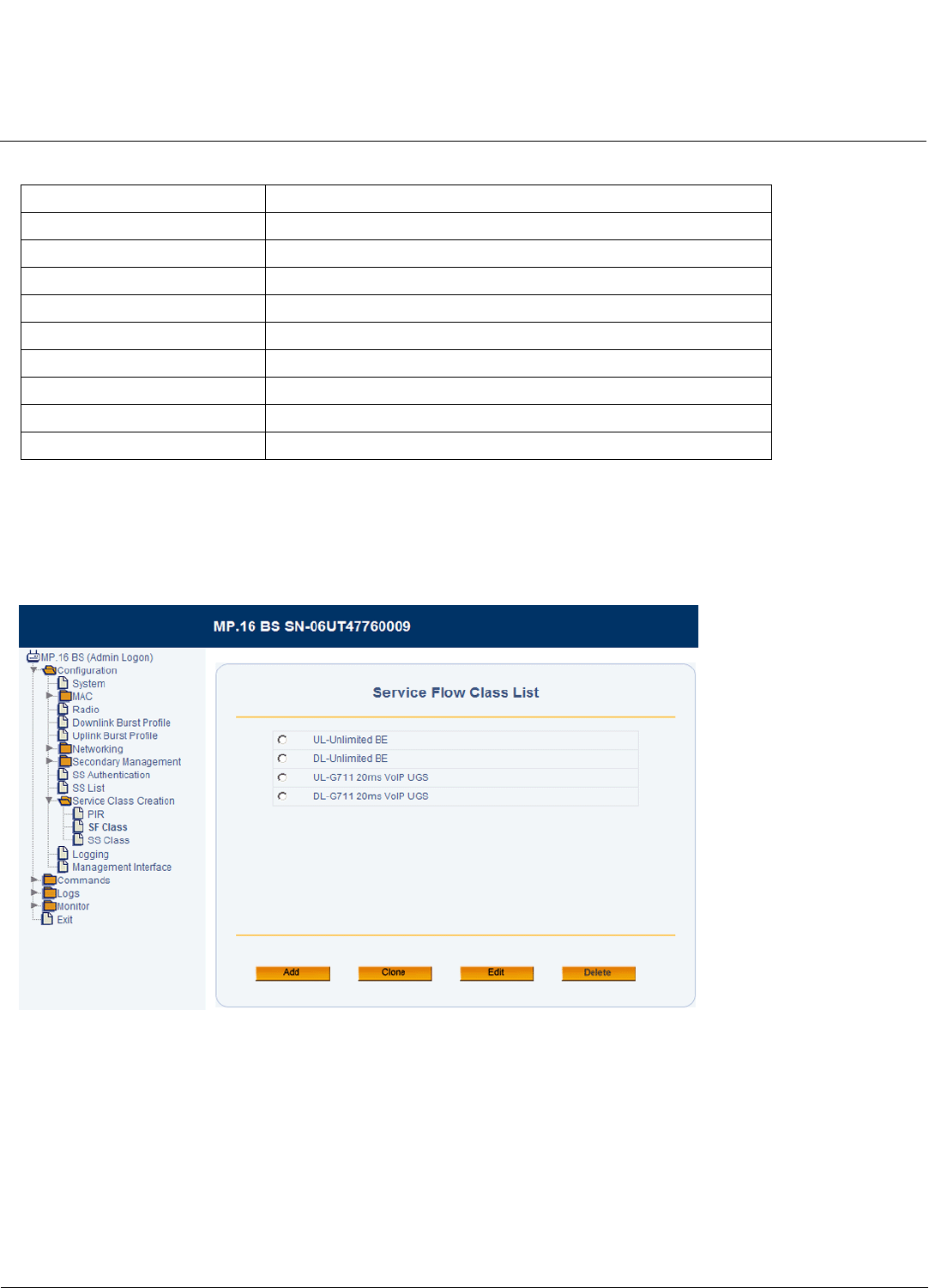
Base Station Configuration Tsunami MP.16 3650 System User Guide
Service Class Creation
88
Service Flow Creation
You can create, delete, and edit up to 256 service flow classes, including those that are predefined for you (see
Pre-Defined Service Flow Classes).
1. Click Service Class Creation > SF Class
Figure 3-44 Service Flow Class List
2. Do one of the following:
• Click Add to create a new SF Class.
• Click the radio button next to one of the SF Classes and click Clone to make a copy of that SF Class.
• Click the radio button next to one of the SF Classes and click Edit an existing SF Class.
• Click the radio button next to one of the SF Classes and click Delete to delete that SF Class from the list.
3. If you are adding or cloning an SF Class, specify a unique name between 1 and 32 characters, and click Add.
PPPoE Data Ethertype (type 1, 0x8864)
IP Ethertype (type 1, 0x800)
ARP Ethertype (type 1, 0x806)
Expedited Forwarding IP TOS/DSCP (low=0x2D, high=0x2D, mask = 0x3F)
Streaming Video (IP/TV) IP TOS/DSCP (low=0x0D, high=0x0D, mask = 0x3F)
802.1p BE Ethernet Priority (low=0, high=0)
802.1p Voice Ethernet Priority (low=6, high=6)
802.1p Video Ethernet Priority (low=5, high=5)
L2 Broadcast/Multicast Ethernet Destination (dest = 0x80000000, mask = 0x80000000)
Table 3-3 Pre-Defined PIRs
PIR Name Classification Fields
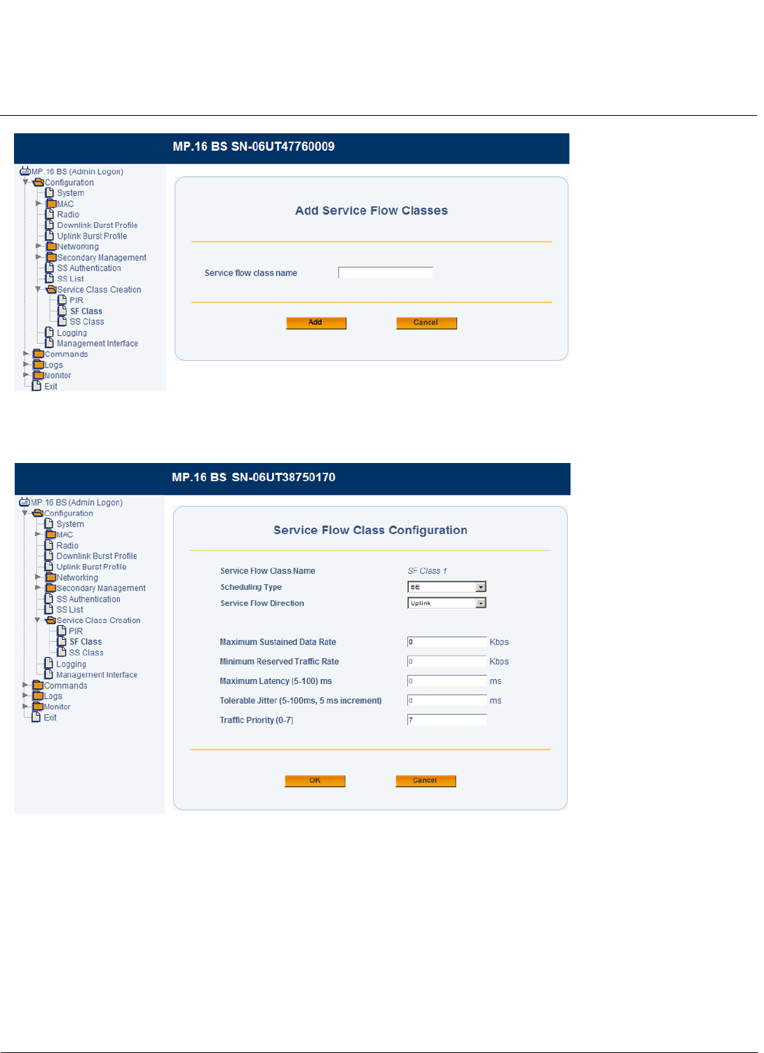
Base Station Configuration Tsunami MP.16 3650 System User Guide
Service Class Creation
89
Figure 3-45 Add Service Flow Classes Screen
The Service Flow Class Configuration page will be displayed.
Figure 3-46 Service Flow Class Configuration Page
4. Configure the Service Flow Class parameters:
•Scheduling Type: The traffic scheduling mechanism used by the uplink or downlink. Select one of the following:
–Best-Effort Service (BE): This mechanism is defined by the following QoS parameters: maximum sustained
data rate and traffic priority. See below.
–Non Real-Time Polling Service (nrtPS): This mechanism is defined by the following QoS parameters: maximum
sustained data rate, minimum reserved traffic rate, and traffic priority. See below.
–Real-Time Polling Services (rtPS): This mechanism is defined by the following QoS parameters: maximum
sustained data rate, minimum reserved traffic rate, and maximum latency. See below.

Base Station Configuration Tsunami MP.16 3650 System User Guide
Service Class Creation
90
–Unsolicited Grant Service (UGS): This mechanism is defined by the following QoS parameters: maximum
sustained data rate, maximum latency, and tolerable jitter. See below.
•Service Flow Direction: Select Uplink or Downlink.
•QoS Parameters
–Maximum Sustained Data Rate: The peak information rate of the service flow. All traffic classified onto a
service flow in excess of this rate is dropped. Set this parameter to unlimited, or to any value between 8 kbps
and 8192 kbps. The default value is unlimited. Set to 0 for unlimited.
–Minimum Reserved Traffic Rate: The minimum reserved traffic rate for the service flow. Set this parameter to
any value between 8 kbps and 8192 kbps. The default value is 0 (unlimited).
–Maximum Latency: The maximum latency between the reception of a packet by the BS or SS on its network
interface and the forwarding of the packet to the RF interface. Set this parameter to any value between 5 ms
and 100 ms, in increments of 5 ms.
–Tolerable Jitter: The maximum delay variation for the connection. Set this parameter to any value between 5
ms and 100 ms, in increments of 5 ms.
–Traffic Priority: The priority assigned to the service flow. Set this parameter to any value between 0 and 7,
where 7 is the highest priority.
5. Click OK.
Pre-Defined Service Flow Classes
The MP.16 system comes with several pre-defined service flow classes that can be used as is, edited, or used as
templates for the creation of new SF classes. These pre-defined classes can be deleted by the administrator; if they are
deleted, they are restored if the system is reset to factory defaults.
The following table describes the pre-defined service flow classes.
Subscriber Station Class Creation
You can create, delete, and edit up to 64 SS classes, including those that are predefined (see Pre-Defined Subscriber
Station Classes). To do so, you will use the SFs and PIRs created the previous sections.
1. Click Service Class Creation > SS Class
Table 3-4 Pre-Defined Service Flow Classes
Service Flow Class Name Scheduling Type Direction Max.
Sustained
Data Rate
Min.
Reserved
Traffic Rate
Max.
Latency
Tolerable
Jitter
Traffic
Priority
UL-Unlimited BE Best Effort Uplink Unlimited 0 — — —
DL-Unlimited BE Best Effort Downlink Unlimited 0 — — —
UL-G711 20ms VoIP UGS Unlimited Grant
Service
Uplink 100 kbps — 20 ms 0 —
DL-G711 20ms VoIP UGS Unlimited Grant
Service
Downlink 100 kbps — 20 ms 0 —
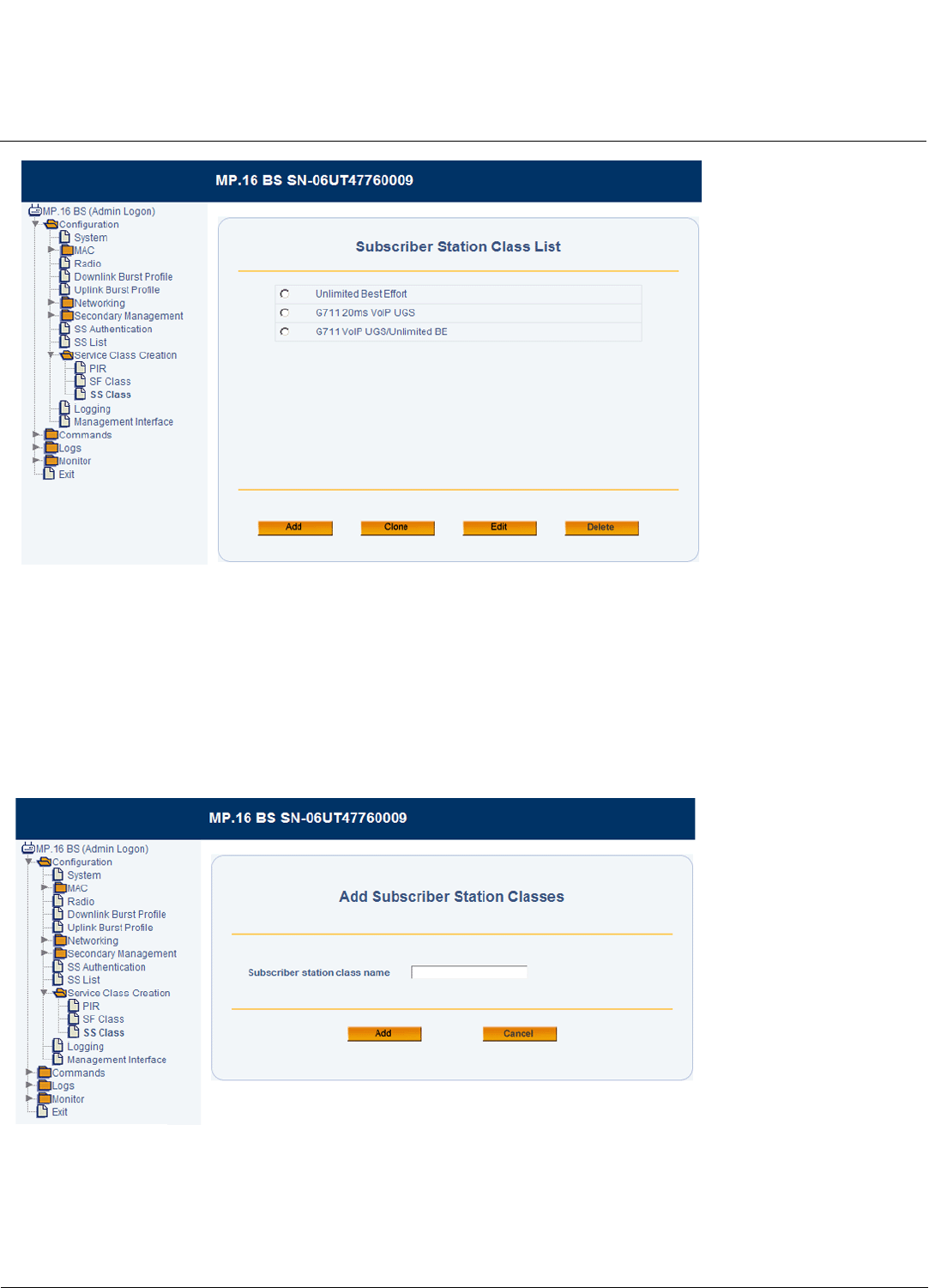
Base Station Configuration Tsunami MP.16 3650 System User Guide
Service Class Creation
91
Figure 3-47 Subscriber Station Class List
2. Do one of the following:
• Click Add to create a new SS Class.
• Click the radio button next to one of the SS Classes and click Clone to make a copy of that SS Class.
• Click the radio button next to one of the SS Classes and click Edit an existing SS Class.
• Click the radio button next to one of the SS Classes and click Delete to delete that SS Class from the list.
3. If you are adding or cloning an SS Class, specify a unique name between 1 and 32 characters, and click Add. If you
are editing an SS class, select the radio button next to the name of the Class you wish to edit, and click Edit.
Figure 3-48 Add Subscriber Station Classes Screen
The Subscriber Station Class wizard will start, and the first of three configuration steps will be displayed. In this step,
you will select Service Flows to add to the SS Class.
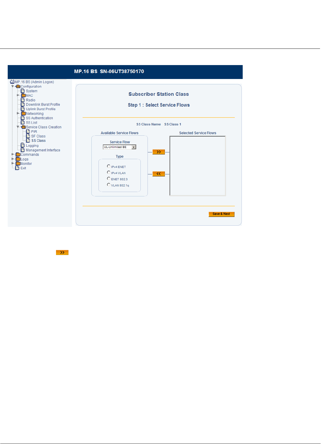
Base Station Configuration Tsunami MP.16 3650 System User Guide
Service Class Creation
92
Step 1: Select Service Flows
Figure 3-49 SS Class Creation Step 1: Select Service Flows
4. Under the Available Service Flows heading, select a Service Flow and Type that are to be used for this class, and click
the right arrow . To remove a service flow, select it and click the left arrow. At least one uplink and one downlink
service flow must be defined. Select a Service Flow Type, based on the following:
• IPv4 ENET: Use this type when associated PIRs use at least one IP classifier and no VLAN classifiers. Ethernet
classifiers are optional.
• IPv4 VLAN: Use this type when associated PIRs use at least one IP classifier and one VLAN classifier.
• ENET 802.3: Use this type when associated PIRs use only Ethernet classifiers.
• VLAN 802.1Q: Use this type when associated PIRs use only VLAN classifiers.
5. Click Save & Next.
The Step 2: Associate PIRs with Service Flow page will be displayed. This page contains a section for each Service
Flow you added in Step 1.
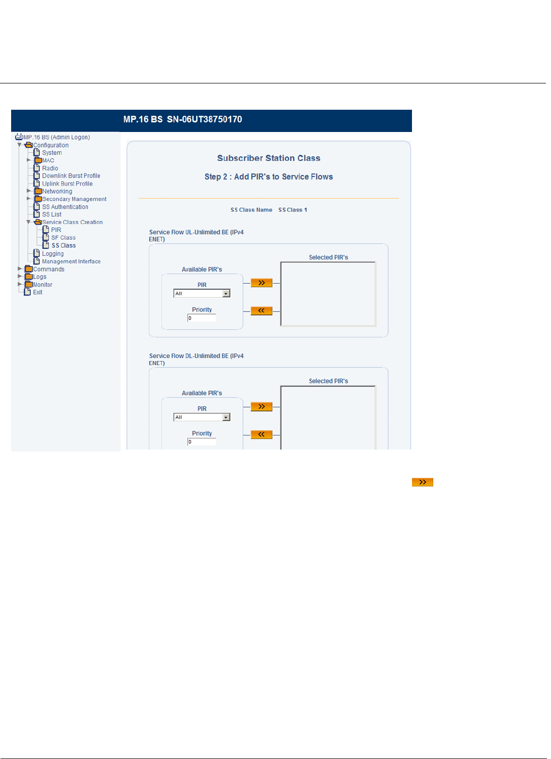
Base Station Configuration Tsunami MP.16 3650 System User Guide
Service Class Creation
93
Step 2: Associate PIRs with Service Flows
Figure 3-50 SS Class Creation Step 2: Add PIRs to Service Flows
1. For each Service Flow, select a PIR, assign it a Priority level, and click the right arrow . To remove a PIR, select
it and click the left arrow. You can add up to 32 PIRs to each Service Flow.
2. Click Save & Next.
The Step 3: Networking Parameters page will be displayed. On this page, you will configure the VLAN settings for
the SS Class.
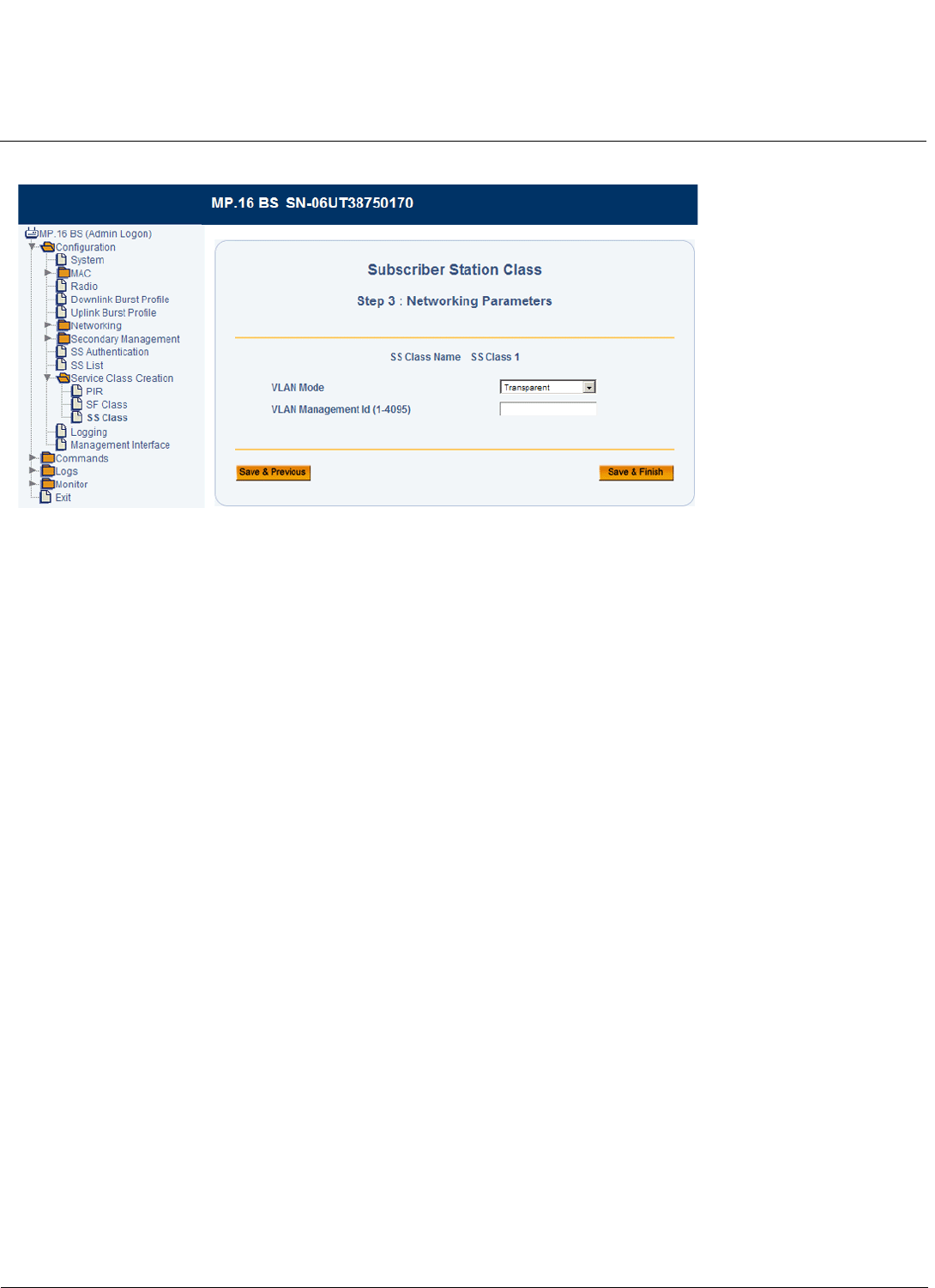
Base Station Configuration Tsunami MP.16 3650 System User Guide
Service Class Creation
94
Step 3: Networking Parameters
Figure 3-51 SS Class Creation Step 3: Networking Parameters (Transparent Mode)
1. Select the VLAN Mode depending on Base Station’s VLAN mode:
• If the BS is configured for VLAN Trunk mode, the SS class can be configured for Trunk, Access, or Mixed mode.
• If the BS is configured for VLAN Transparent mode, the SS class can be configured for either Transparent or
Access mode.
2. If the VLAN mode is set to Transparent, click Save & Finish.
NOTE: The VLAN Management ID parameter has no effect when VLAN Mode is set to Transparent. This field is not
configurable.
3. If the VLAN mode is set to Access, Trunk, or Mixed, see Configuring an SS Class for Access Mode or Configuring
an SS Class for Trunk Mode.
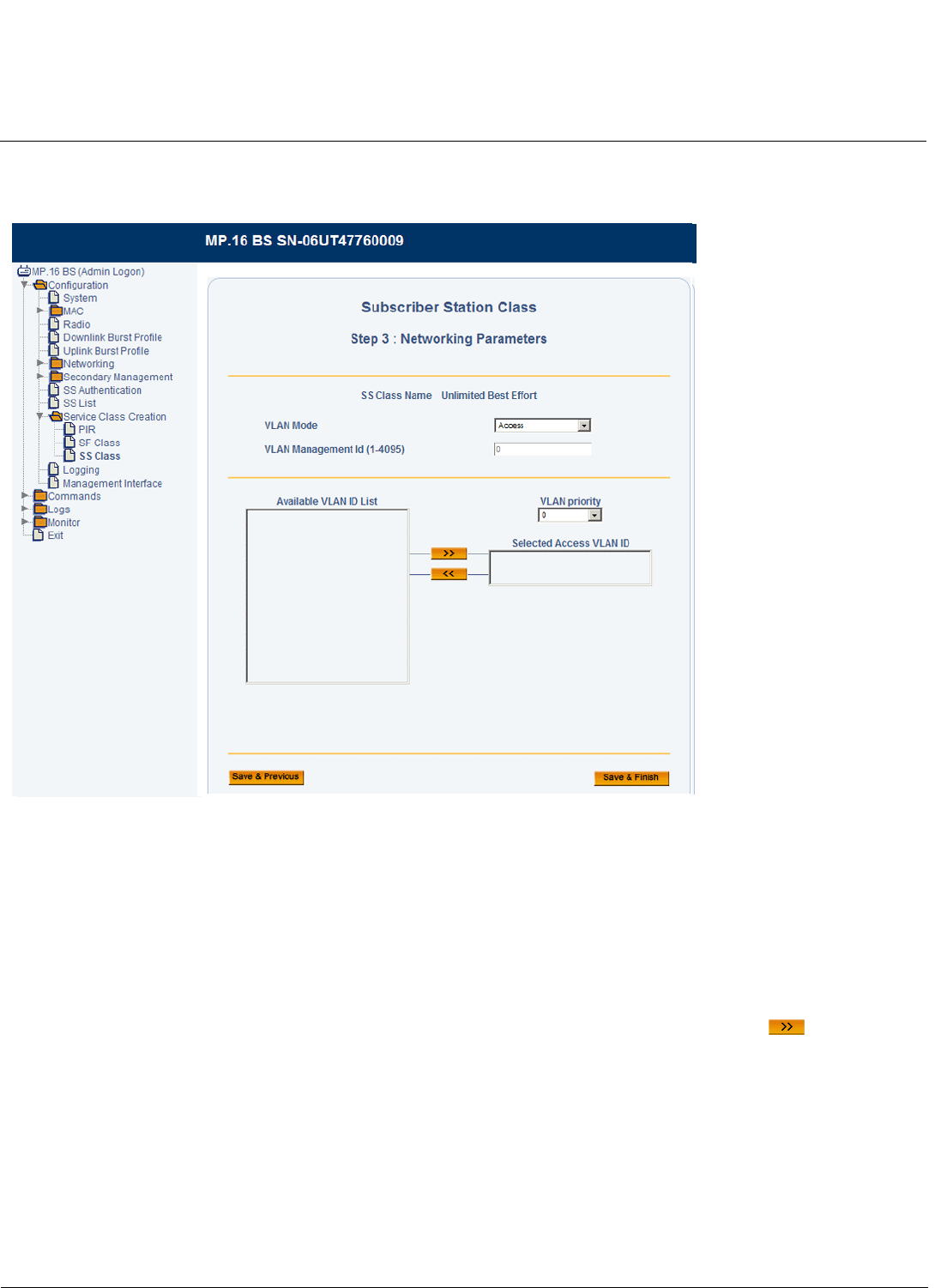
Base Station Configuration Tsunami MP.16 3650 System User Guide
Service Class Creation
95
Configuring an SS Class for Access Mode
With the VLAN mode set to Access, the following screen will be displayed:
Figure 3-52 SS Class Creation Step 3: Networking Parameters (Access Mode)
In Access mode, only one VLAN ID may be specified as having access to the SS. This VLAN ID has management
access.
NOTE: When you move the VLAN ID to the Selected Access VLAN ID list, the VLAN Management ID field will be
automatically populated with this ID.
Set the following parameters and then click Save & Finish:
•Selected VLAN Access ID: Select one VLAN ID from the Available VLAN ID List to serve as the Management ID.
Only VLAN packets tagged with this ID will have access to and be able to manage the SS. To designate a VLAN ID as
the Management ID, select the VLAN ID from Available VLAN ID List, and click the right arrow . To designate a
different VLAN ID as the Management ID, remove the current VLAN ID by clicking the left arrow, and select a different
VLAN ID from the list.
•VLAN Priority: Priority to be given to the Selected Access VLAN ID; select a number between 0 and 7.
For information on configuring the Available VLAN ID List, see VLAN ID List.
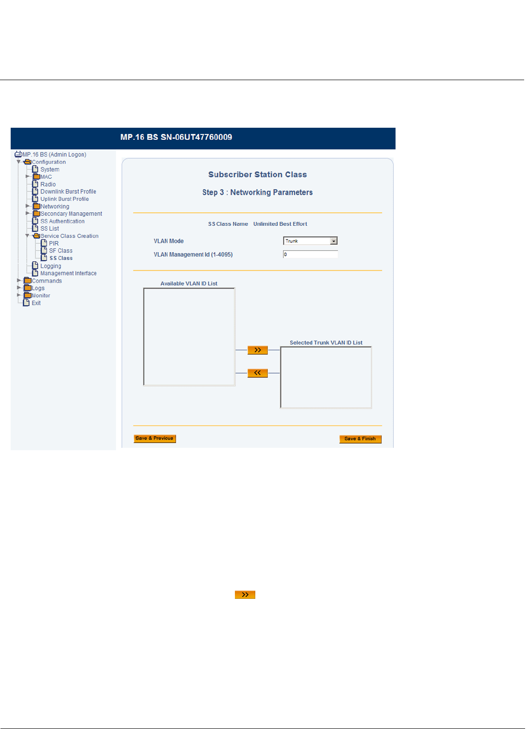
Base Station Configuration Tsunami MP.16 3650 System User Guide
Service Class Creation
96
Configuring an SS Class for Trunk Mode
With the VLAN mode set to Trunk, the following screen will be displayed:
Figure 3-53 SS Class Creation Step 3: Networking Parameters (Trunk Mode)
In Trunk mode, up to 16 VLAN IDs may be specified as having access to the SS. Additionally, one of these VLAN IDs
must be designated as the VLAN Management ID for the VLAN.
NOTE: The total number of VLANs and Service Flows must not exceed 20.
Set the following parameters and click OK:
•VLAN Management ID: Select one VLAN ID from the Selected Trunk VLAN ID List to serve as the Management ID.
Only VLAN packets tagged with this ID will have management access to the SS. If the VLAN ID entered in this field is
not contained in the Selected Trunk VLAN ID List, an error message will be displayed when you click OK.
•Selected VLAN ID List: You may add up to 16 VLAN IDs to this list. To add a VLAN ID, select the VLAN ID from
Available VLAN ID List, and click the right arrow . To remove a VLAN ID from the list, select the ID and click the
left arrow.
NOTE: After clicking OK, the selected Management ID will be automatically moved to the top of the Selected Trunk
VLAN ID List.
For information on configuring the Available VLAN ID List, see VLAN ID List.
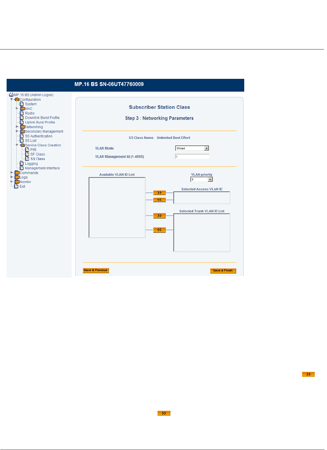
Base Station Configuration Tsunami MP.16 3650 System User Guide
Service Class Creation
97
Configuring an SS Class for Mixed Mode
With the VLAN mode set to Mixed, the following screen will be displayed:
Figure 3-54 SS Class Creation Step 3: Networking Parameters (Mixed Mode)
In Mixed mode, one VLAN Access ID and up to 16 VLAN Trunk IDs may be specified as having access to the SS. The
VLAN Access ID has management access.
NOTE: When you move a VLAN ID to the Selected Access VLAN ID list, the VLAN Management ID field will be
automatically populated with this ID.
NOTE: The total number of VLANs and Service Flows must not exceed 20. When using Mixed mode, this number
includes the Access VLAN ID as well as the Trunk VLAN IDs.
Set the following parameters and click OK:
•Selected Access VLAN ID: Select one VLAN ID from the Available VLAN ID List to serve as the Selected Access
VLAN ID. Only VLAN packets tagged with this ID will have access to and be able to manage the SS. To designate a
VLAN ID as the Access VLAN ID, select the VLAN ID from Available VLAN ID List, and click the right arrow . To
designate a different VLAN ID as the Management ID, remove the current VLAN ID by clicking the left arrow, and
select a different VLAN ID from the list.
•VLAN Priority: Priority to be given to the Selected Access VLAN ID; select a number between 0 and 7.
•Selected Trunk VLAN ID List: You may add up to 16 VLAN IDs to this list. To add a VLAN ID, select the VLAN ID
from Available VLAN ID List, and click the right arrow . To remove a VLAN ID from the list, select the ID and click
the left arrow.
For information on configuring the Available VLAN ID List, see VLAN ID List.

Base Station Configuration Tsunami MP.16 3650 System User Guide
Service Class Creation
98
Pre-Defined Subscriber Station Classes
The MP.16 system comes with several pre-defined SS classes that can be used as is, edited, or used as templates for
the creation of new SF classes. These pre-defined classes can be deleted by the administrator; if they are deleted, they
are restored if the system is reset to factory defaults.
The following table describes the pre-defined SS classes.
NOTE: Pre-defined SS Classes have a VLAN mode of “Transparent.”
Table 3-5 Pre-Defined SS Classes
SS Class Name Uplink Downlink
SF Class Name(s) PIR(s) Priority SF Class Name(s) PIR(s) Priority
Unlimited Best Effort UL-Unlimited BE All 0 DL-Unlimited BE All 0
G711 VoIP UGS UL-G711 20ms UGS All 0 DL-G711 20ms UGS All 0
G711 VoIP UGS/Unlimited
BE
UL-Unlimited BE
UL-G711 20ms UGS
All
Vonage VoIP UL
Cisco VoIP UL
0
1
1
UL-Unlimited BE
DL-G711 20ms UGS
All
Vonage VoIP DL
Cisco VoIP DL
0
1
1
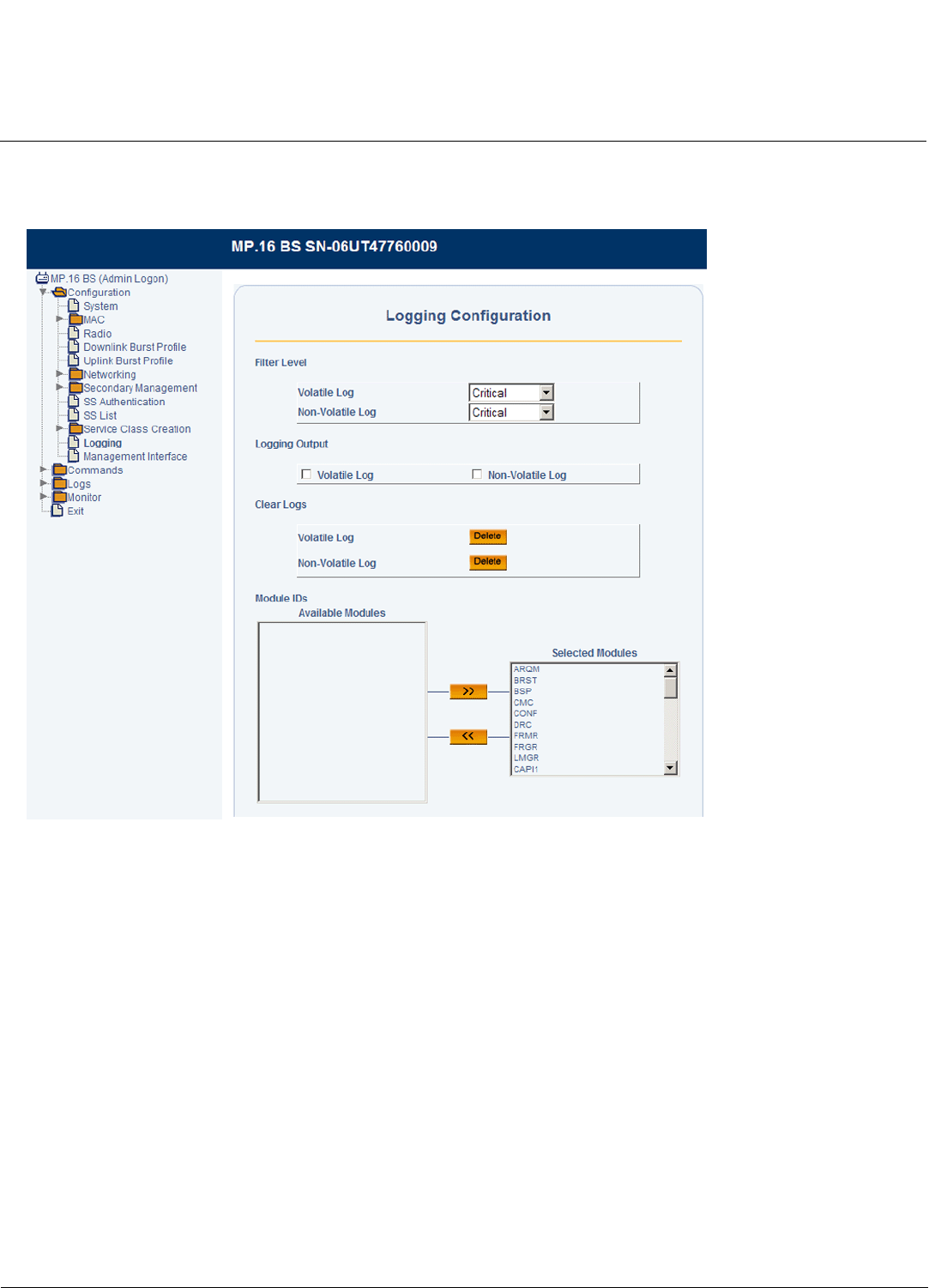
Base Station Configuration Tsunami MP.16 3650 System User Guide
Logging Configuration
99
Logging Configuration
From the Logging Configuration page, you can set the parameters for the logging functions of the BS.
Figure 3-55 Logging Configuration
The following logging parameters can be configured or viewed:
•Filter Level: For both the volatile (stored in RAM) and non-volatile (stored in Flash), select the minimum logging level.
•Logging Output: Select the desired output locations:
–Select Volatile Log to save the log to the RAM. Note that information stored to the RAM may be lost in the event
of a power cycle.
–Select Non-Volatile Log to save the log to the flash.
•Clear Logs: Press Delete to clear the contents of the specified log.
•Module IDs: Select the modules for which logging should be enabled.
Once logging is configured, logs can be viewed on the Logs page.
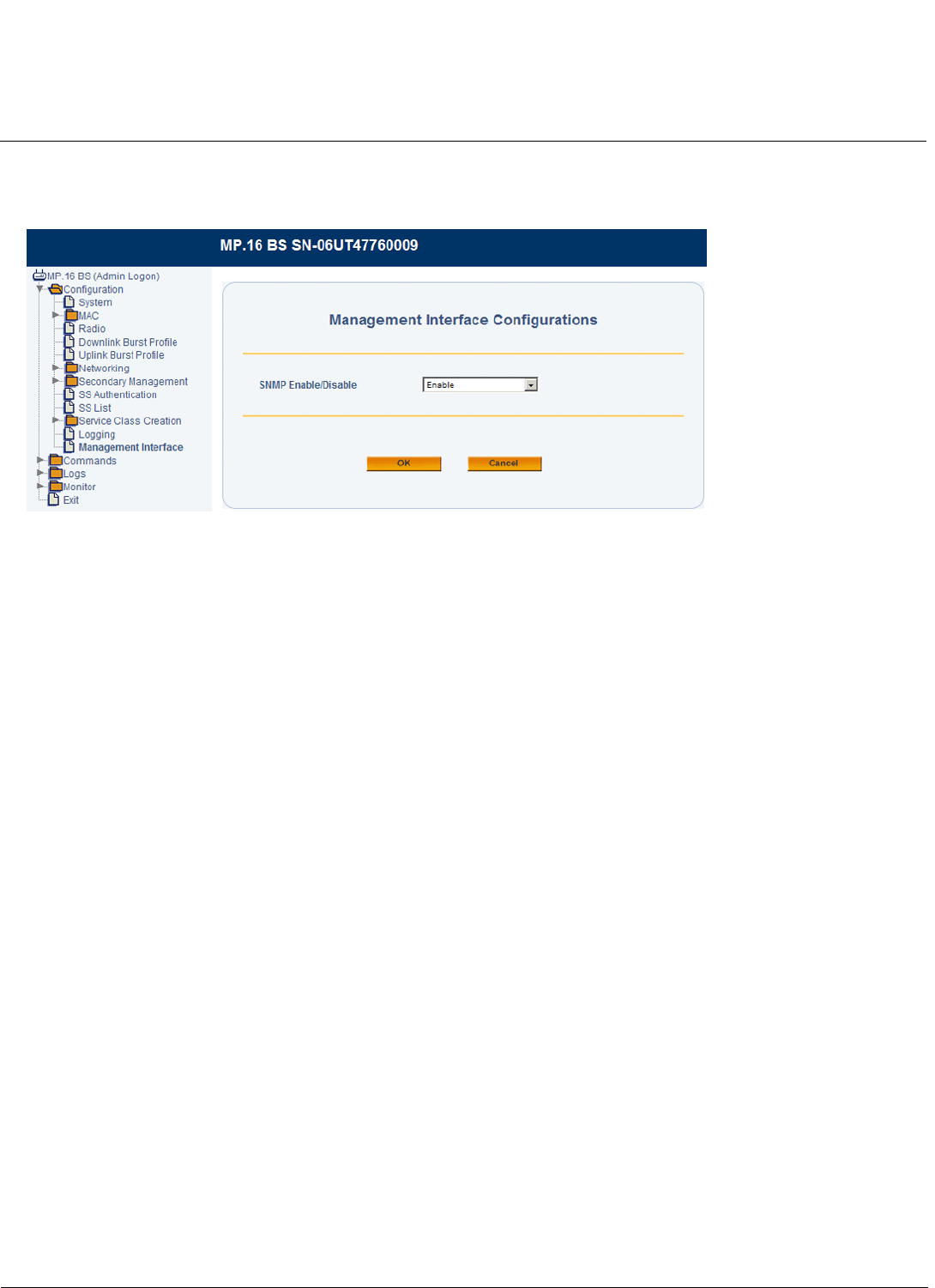
Base Station Configuration Tsunami MP.16 3650 System User Guide
Management Interface Configuration
100
Management Interface Configuration
From the Management Interface page, you can enable or disable SNMP management.
Figure 3-56 Management Interface Configuration

101
Tsunami MP.16 3650 System User Guide
4
Subscriber Station Configuration
To configure local SS parameters via the web, log in to the SS’s web interface.
For information on configuring the SS via the CLI, see Configuration from the Subscriber Station in the Command Line
Interface chapter.
After logging in to the SS, you can access the following configuration pages:
•System Configuration
•Radio Configuration
•Network Configuration
•Syslog Configuration
•Logging Configuration
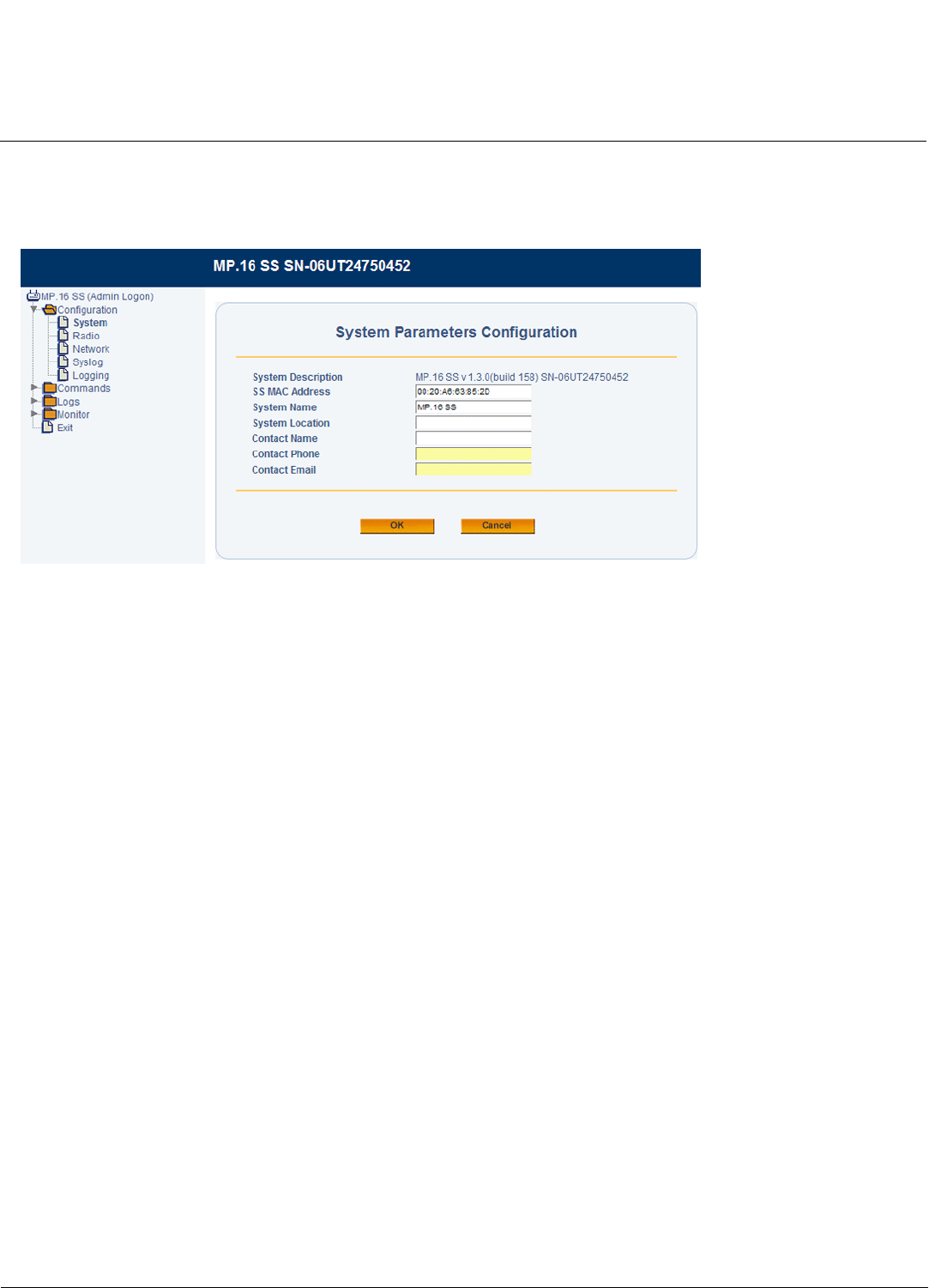
Subscriber Station Configuration Tsunami MP.16 3650 System User Guide
System Configuration
102
System Configuration
To access the System Configuration page, click Configuration > System. The System Configuration page allows you to
set and view SS-specific MAC address, name, location, and contact information.
Figure 4-1 SS System Configuration Parameters
The following parameters can be configured or viewed from the System Configuration page:
•System Description: A read-only description of the Subscriber Station, including software version and build
information.
•SS MAC Address: The MAC address of the SS.
•System Name: The name assigned to SS. Enter a value between 1 and 255 alphanumeric characters.
•System Location: The location where the SS is installed. Enter a value between 1 and 255 alphanumeric characters.
•Contact Name: The name of the person responsible for the SS. Enter a value between 1 and 255 alphanumeric
characters.
•Contact Phone: The telephone number of the person responsible for the SS. Enter a value between 1 and 255
alphanumeric characters.
•Contact Email: The email address of the person responsible for the SS. Enter a value between 1 and 255
alphanumeric characters.
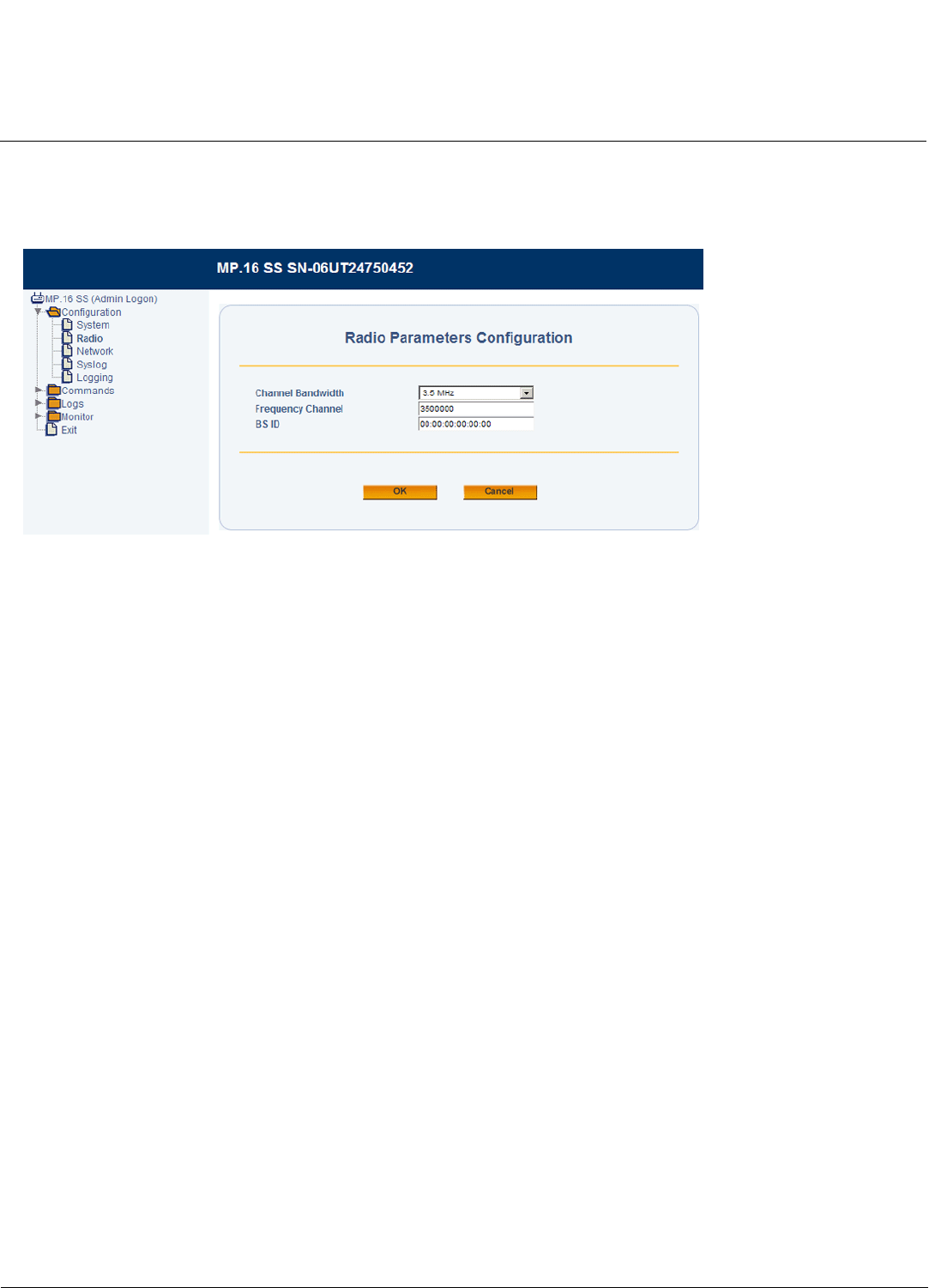
Subscriber Station Configuration Tsunami MP.16 3650 System User Guide
Radio Configuration
103
Radio Configuration
From the SS Radio configuration page, you can control the channel bandwidth and frequency, and specify a BS
connection.
Figure 4-2 SS Radio Parameters Configuration
The following parameters may be set or viewed:
•Channel Bandwidth: Select a channel bandwidth of 3.5 MHz or 7 MHz.
•Frequency Channel: Set the desired center frequency.
•BS ID: Set the specific ID of the Base Station with which the SS communicates, or set this parameter to “Any” to
connect to any available Base Station (the default).
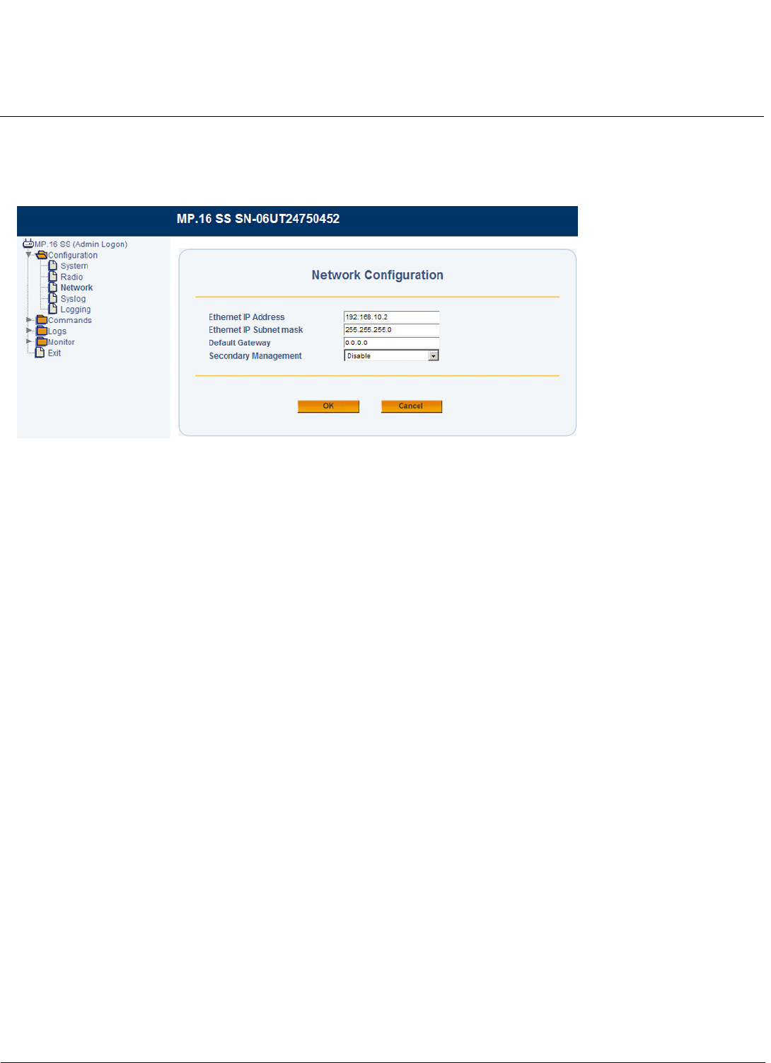
Subscriber Station Configuration Tsunami MP.16 3650 System User Guide
Network Configuration
104
Network Configuration
From the SS Network configuration page, you can set the Ethernet IP address and mask, specify the default gateway,
and enable/disable secondary management functionality.
Figure 4-3 SS Network Configuration
The following parameters may be set or viewed:
•Ethernet IP Address: Enter an IP address and subnet for the unit’s Ethernet port. The default IP address of the SS is
192.168.10.2.
•Ethernet IP Subnet Mask: Select a subnet mask for the unit’s Ethernet port. The default mask is 255.255.255.0
•Default Gateway: Enter an IP address to serve as the default IP gateway.
• Secondary Management: Use the drop-down menu to enable or disable secondary management support. See Global
Positioning System (GPS) in the Base Station Configuration chapter for more information.
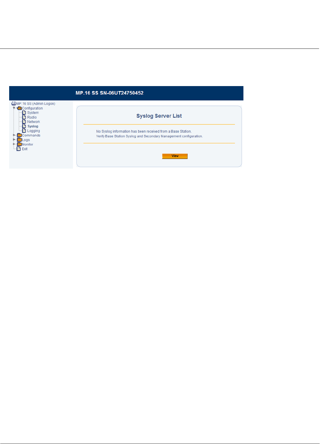
Subscriber Station Configuration Tsunami MP.16 3650 System User Guide
Syslog Configuration
105
Syslog Configuration
When Secondary Management is enabled, the Syslog Server List displays the IP addresses of the Syslog servers
configured on the BS.
Figure 4-4 Syslog Server List
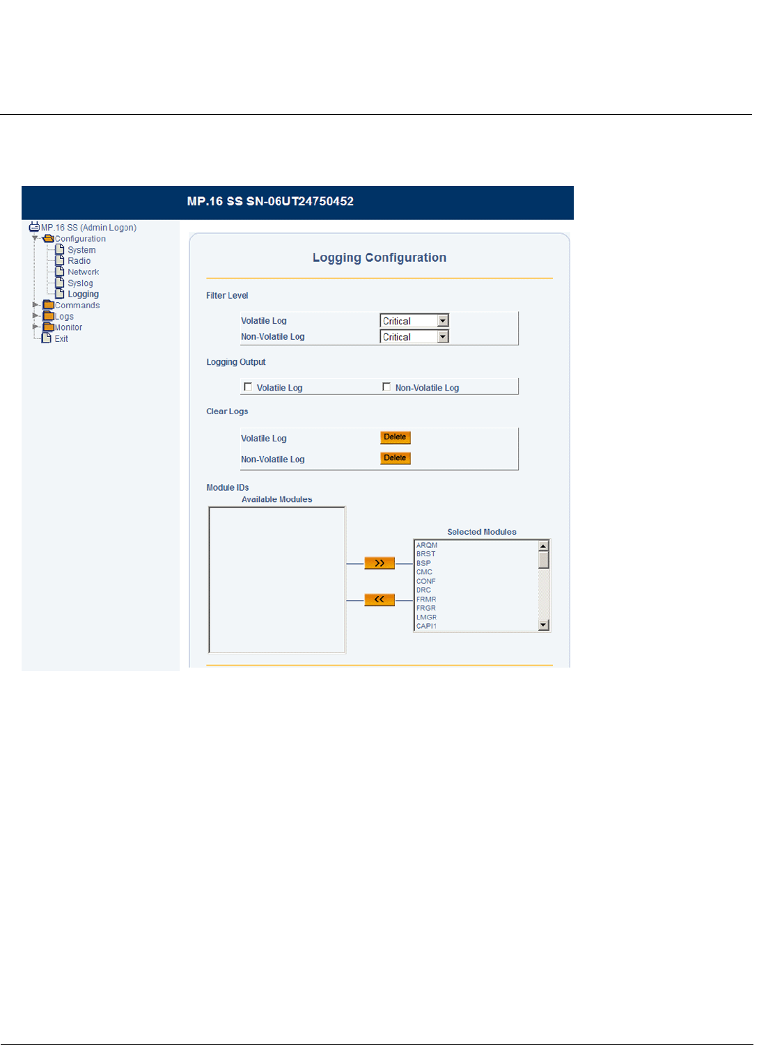
Subscriber Station Configuration Tsunami MP.16 3650 System User Guide
Logging Configuration
106
Logging Configuration
From the Logging Configuration page, you can set the parameters for the logging functions of the SS.
Figure 4-5 Logging Configuration

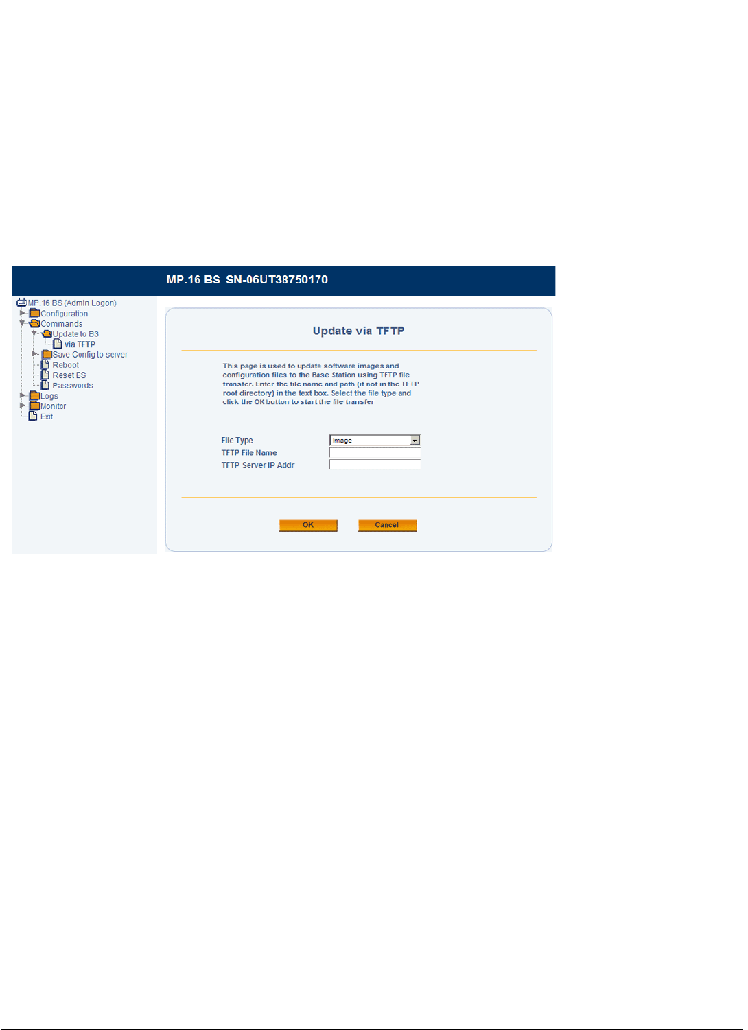
Commands on BS/SS Tsunami MP.16 3650 System User Guide
Update to BS/SS
108
Update to BS/SS
Update via TFTP
Use the Update page to update software images and configuration files to the unit. A TFTP server must be running and
configured to point to the directory containing the file.
If you do not have a TFTP server installed on your system, install the TFTP server from the Installation CD.
Figure 5-1 Update via TFTP Screen
The Update page contains the following parameters:
•File Type: Select the proper file type. Choices include:
–Config: configuration information, such as System Name, Contact Name, and so on.
–Image: BS/SS Image (executable program).
•File Name: Enter the name of the file to be downloaded (including the file extension). This file must be in the TFTP
server’s local root directory.
•TFTP Server IP Address: Enter the TFTP server IP Address. This is the IP address that will be used to point the unit
to the Image file.
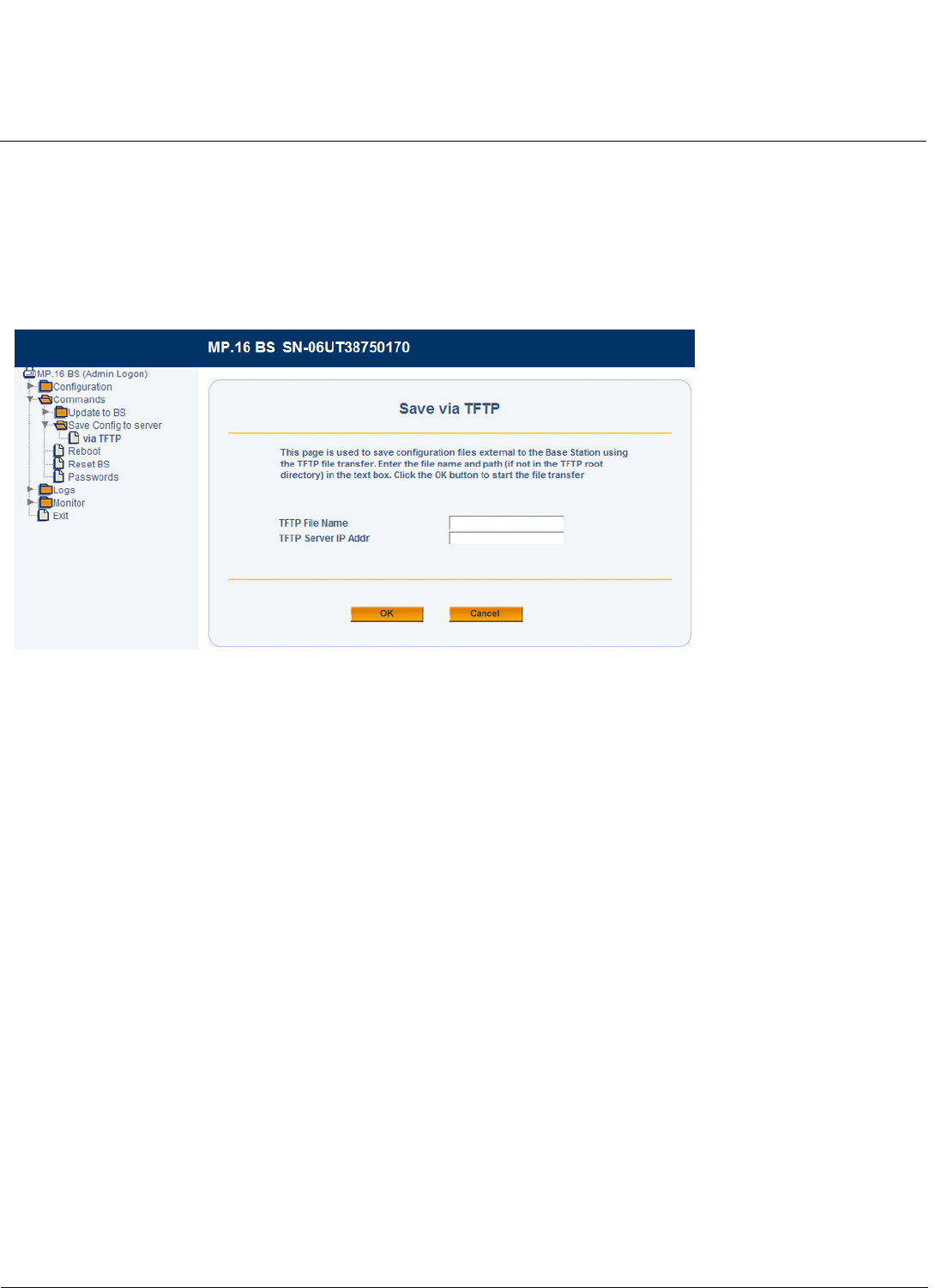
Commands on BS/SS Tsunami MP.16 3650 System User Guide
Save Config to Server (BS Only)
109
Save Config to Server (BS Only)
Save via TFTP
On the BS, use the Save via TFTP page to save configuration to a location external to the unit. A TFTP server must be
running and configured to point to the directory containing the file.
If you do not have a TFTP server installed on your system, install the TFTP server from the Installation CD.
Figure 5-2 Save via TFTP Screen
The Update page contains the following parameters:
•File Name: Enter the name of the file to be saved (including the file extension).
•TFTP Server IP Address: Enter the IP Address of the TFTP server where the file is to be placed.
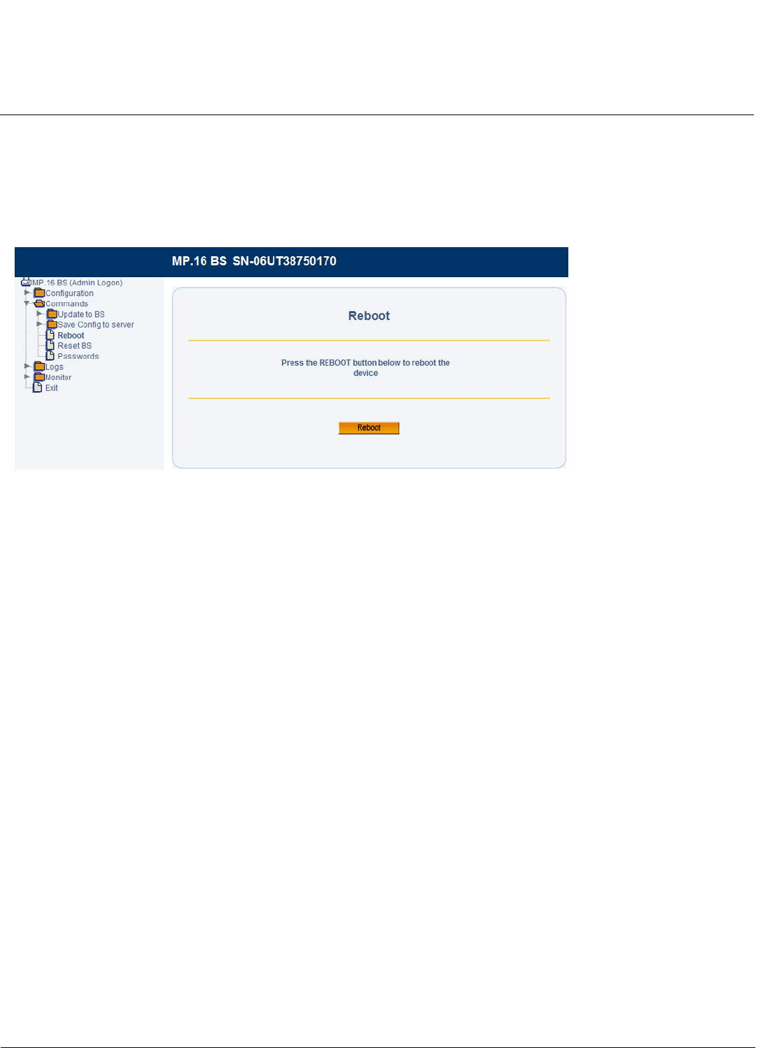
Commands on BS/SS Tsunami MP.16 3650 System User Guide
Reboot
110
Reboot
Use the Reboot tab to save configuration changes (if any) and reset the unit. Note that Reset, described below, discards
configuration changes.
CAUTION: Rebooting the unit will cause all users who are currently connected to lose their connection to the network
until the unit has completed the restart process and resumed operation.
Figure 5-3 Reboot Screen
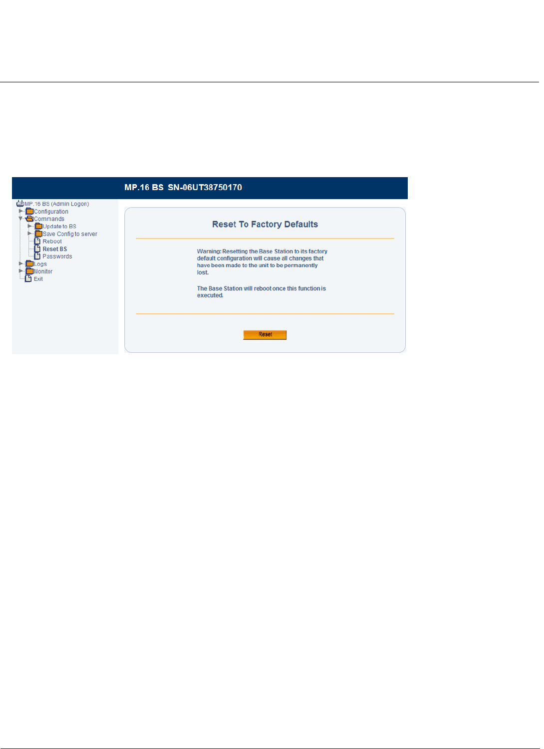
Commands on BS/SS Tsunami MP.16 3650 System User Guide
Reset
111
Reset
Use the Reset tab to restore the unit to factory default conditions. Since this will reset the current IP address, a new IP
address must be assigned. The unit will reboot automatically after this command has been issued.
CAUTION: Resetting the unit to its factory default configuration will permanently overwrite all configuration changes to
date.
Figure 5-4 Reset to Factory Defaults Screen
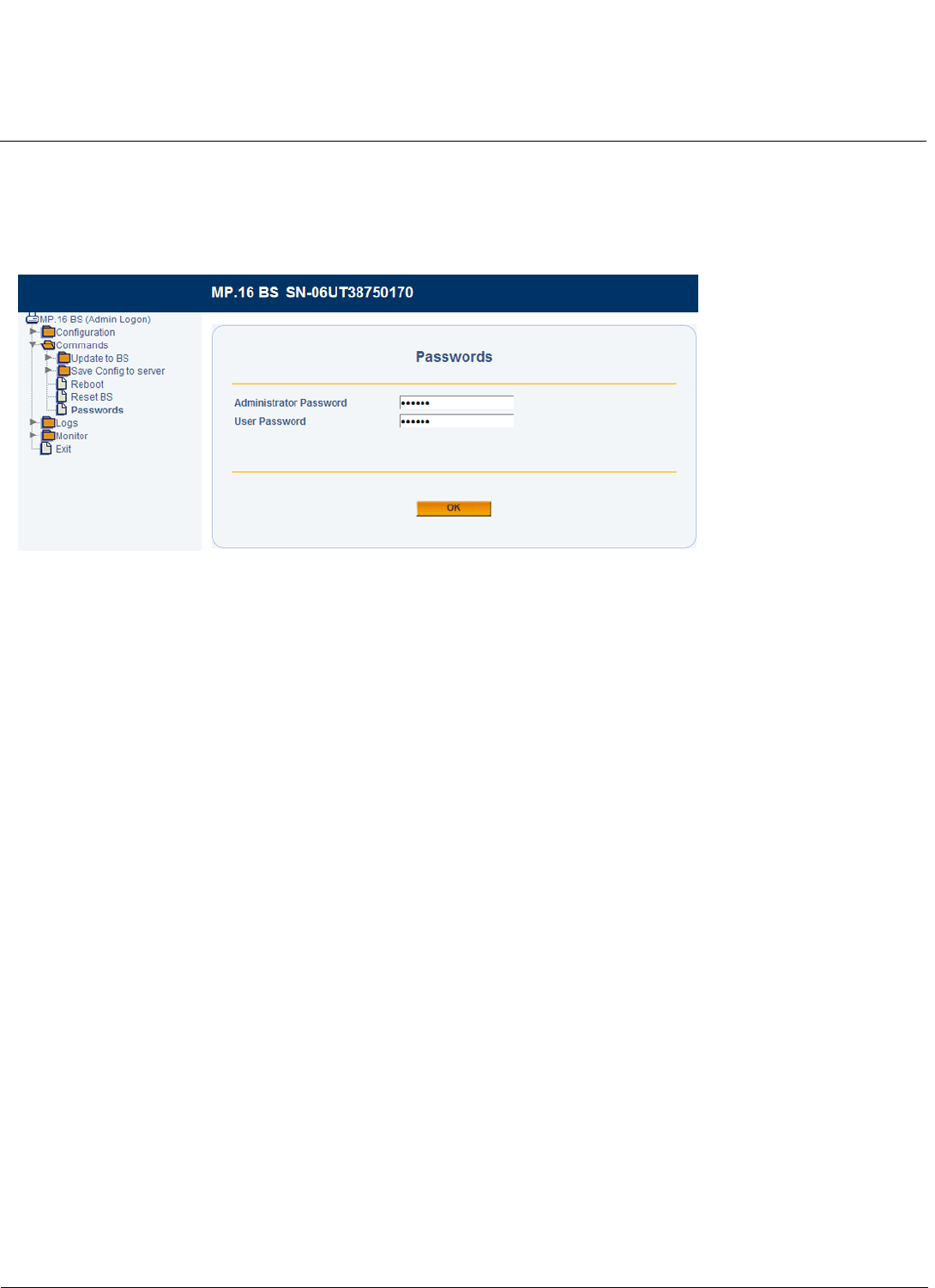
Commands on BS/SS Tsunami MP.16 3650 System User Guide
Passwords
112
Passwords
Use the Passwords page to change the management passwords for the BS/SS. If you are logged on as an
administrator, you can change the administrator-level password or the user-level password. If you are logged on as a
user, you can change only the user-level password.
Figure 5-5 Passwords Screen
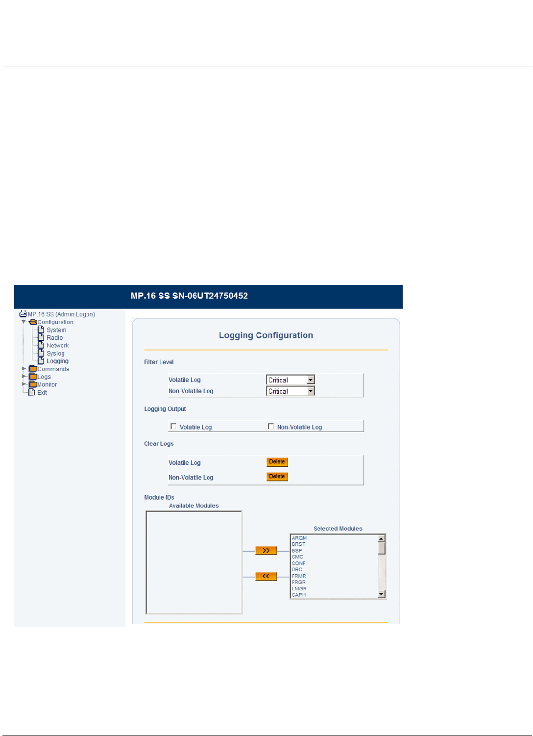
113
Tsunami MP.16 3650 System User Guide
6
Log Messages on the BS/SS
See the following sections:
•Logging Configuration
•Log Messages
Logging Configuration
On the BS, logging is configured on the Configure > Logging. See Logging Configuration in the Base Station
Configuration chapter.
On the SS, logging is configured from the Logs > Configuration page (shown here).
Figure 6-1 Logging Configuration (Subscriber Station)
The following logging parameters can be configured or viewed:
•Filter Level: For both the volatile (temporary) and non-volatile (permanent), select the minimum logging level.
•Logging Output: Select the desired output locations:

Log Messages on the BS/SS Tsunami MP.16 3650 System User Guide
Logging Configuration
114
–Select Volatile Log to save the log to the RAM. Note that information stored to the RAM may be lost in the event
of a power cycle.
–Select Non-Volatile Log to save the log to the flash.
•Clear Logs: Press Delete to clear the contents of the specified log.
•Module IDs: Select the modules for which logging should be enabled.
Once logging is configured, logs can be viewed by clicking on Monitor > Logs tab in the web interface. See Log
Messages on the BS/SS for more information.
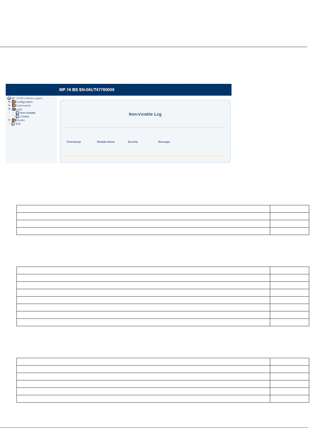
Log Messages on the BS/SS Tsunami MP.16 3650 System User Guide
Log Messages
115
Log Messages
Log messages for both the Base Station and Subscriber Stations can be monitored by the administrator. You can view log
messages for either the non-volatile or the volatile memory.
Figure 6-2 Non-Volatile Message Log Page
Common Log Messages
The following log messages are supported on both the Subscriber Station and the Base Station:
Base Station Log Messages
The following log messages are supported in the Base Station:
Subscriber Station Log Messages
The following log messages are supported at the Subscriber Station:
Log Message Severity
Invalid HTTP Login Warning
Invalid SNMP Community Warning
Invalid CLI Login Warning
Log Message Severity
Subscriber station xx:xx:xx:xx:xx:xx successfully entered the network Informational
Subscriber station xx:xx:xx:xx:xx:xx authorization failure Warning
Subscriber station xx:xx:xx:xx:xx:xx exited the network Informational
Subscriber station xx:xx:xx:xx:xx:xx adapted uplink/downlink from y to z. (e.g., y,z = BPSK-1/2) Informational
No response from Radius Server Alert
Service Flow xxxx successfully activated Informational
Subscriber station xx:xx:xx:xx:xx:xx power adjusted by # dB Informational
Log Message Severity
Subscriber station adjusted power by # dB Informational
Service Flow xxxx successfully activated Informational
Subscriber station lost link to BSID xx:xx:xx:xx:xx:xx Alert
Subscriber station successfully connected to BSID xx:xx:xx:xx:xx:xx Informational
Subscriber station requesting downlink adaptation from y to z Informational

116
Tsunami MP.16 3650 System User Guide
7
Monitoring the BS and SS
Statistics for both the Base Station and Subscriber Stations can be monitored by the administrator.
•Base Station Monitoring
–BS Ethernet Statistics
–BS MAC Statistics
–Service Flow Statistics
–Registered SS Statistics
–System Inventory
–GPS Status
•Subscriber Station Monitoring
–SS Ethernet Statistics
–SS MAC Statistics
–SS Service Flow Statistics
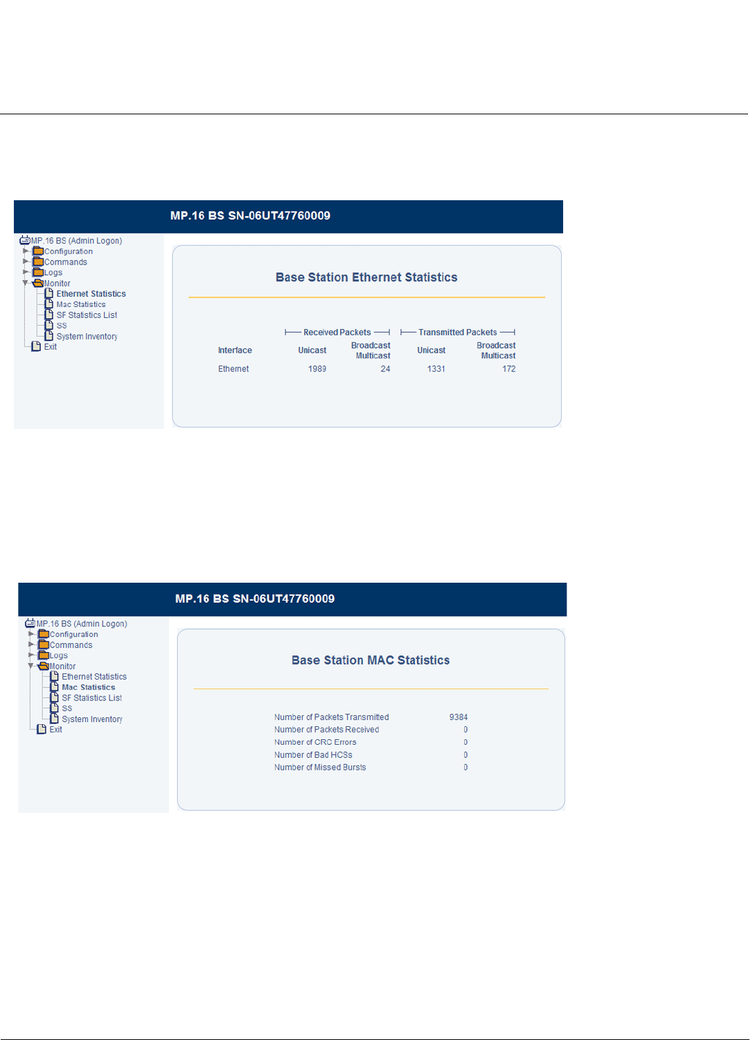
Monitoring the BS and SS Tsunami MP.16 3650 System User Guide
Base Station Monitoring
117
Base Station Monitoring
BS Ethernet Statistics
Figure 7-1 BS Ethernet Statistics
The BS displays the following interface statistics:
• Unicast and multicast packets received
• Unicast and multicast packets transmitted
BS MAC Statistics
Figure 7-2 BS MAC Statistics
The BS displays the following MAC statistics:
• Packets transmitted
• Packets received
• Number of CRC errors
• Number of bad HCSs
• Number of missed bursts
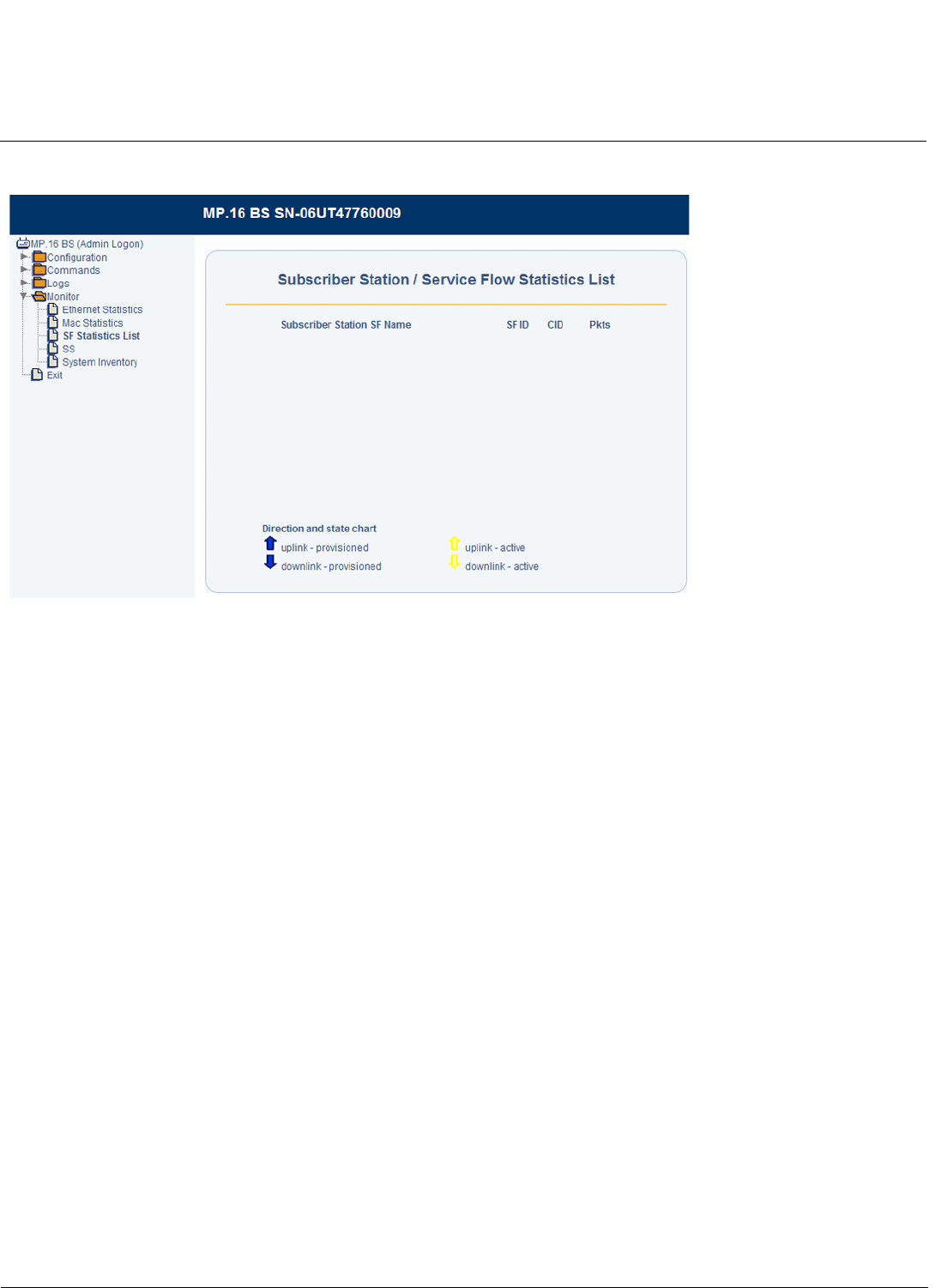
Monitoring the BS and SS Tsunami MP.16 3650 System User Guide
Base Station Monitoring
118
Service Flow Statistics
Figure 7-3 Service Flow Statistics
This screen provides information on each Service Flow that has been provisioned (whether active or inactive) to SSs.
Arrows indicate whether the SF is uplink or downlink. The following statistics are displayed for each SF:
•Direction and State: The colored arrows on the page indicate the direction and state of each SF.
•Subscriber Station: The MAC address of the SS using the Service Flow.
•SF Name: The name of the Service Flow.
•SFID: The Service Flow’s ID number
•CID: The connection ID (if connected)
•Pkts: The number of packets sent or received (active flows only).
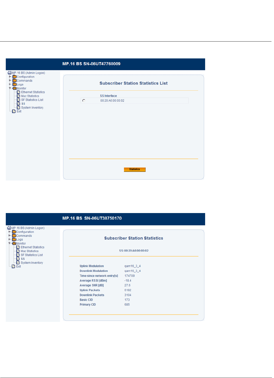
Monitoring the BS and SS Tsunami MP.16 3650 System User Guide
Base Station Monitoring
119
Registered SS Statistics
Figure 7-4 SS Statistics Screen
This screen provides information on each SS currently registered with the BS. Select the required SS and click the
Statistics button. The following page is displayed:
Figure 7-5 SS Statistics Detail Screen
This page contains information about the following:
• Uplink modulation
• Downlink modulation
• Elapsed time since network entry
• Average RSSI
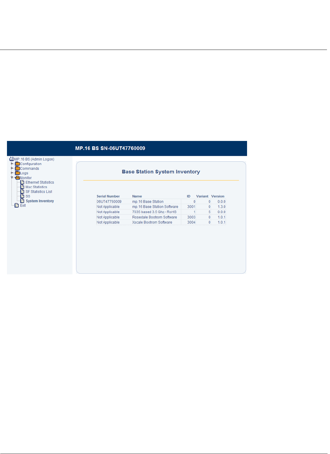
Monitoring the BS and SS Tsunami MP.16 3650 System User Guide
Base Station Monitoring
120
• Average SNR
• Uplink packets
• Downlink packets
• Basic CID
• Primary CID
System Inventory
The System Inventory page provides information on the components of the system, including hardware, software, and
radio components.
Figure 7-6 System Inventory Screen
GPS Status
The GPS Status page displays information related to GPS functionality.
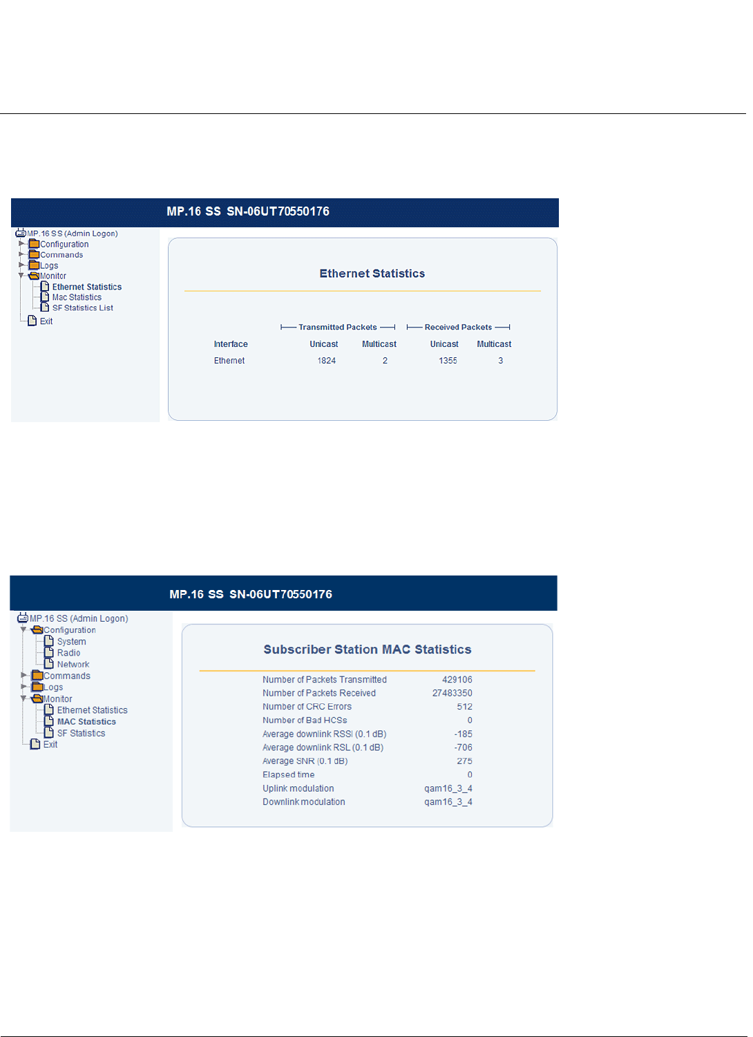
Monitoring the BS and SS Tsunami MP.16 3650 System User Guide
Subscriber Station Monitoring
121
Subscriber Station Monitoring
SS Ethernet Statistics
Figure 7-7 SS Ethernet Statistics
The SS displays the following statistics on a per-interface basis.
• Unicast and multicast packets transmitted
• Unicast and multicast packets received
SS MAC Statistics
Figure 7-8 SS MAC Statistics
The following statistics can be displayed for the SS MAC:
• Packets transmitted
• Packets received
• CRC errors
• Bad HCSs
• Downlink RSL
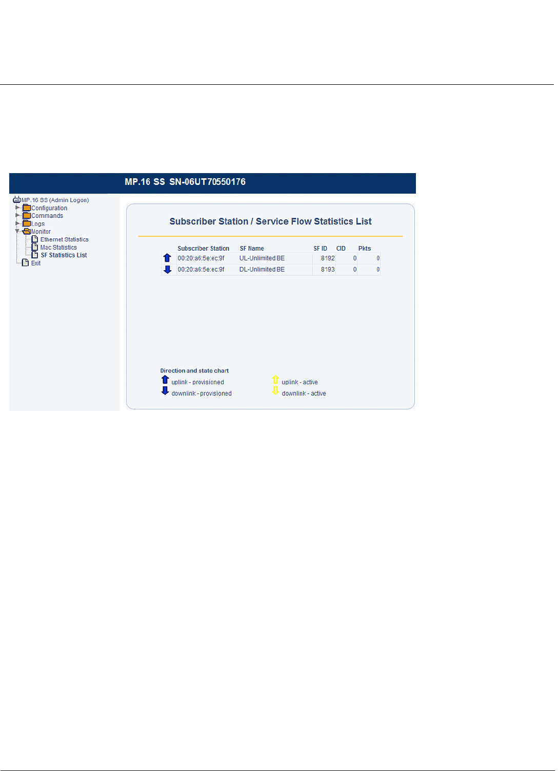
Monitoring the BS and SS Tsunami MP.16 3650 System User Guide
Subscriber Station Monitoring
122
• Average SNR
• Current uplink and downlink modulations
• Elapsed time since network entry
SS Service Flow Statistics
Figure 7-9 SS Service Flow Statistics
This screen provides information on each Service Flow that has been provisioned (whether active or inactive) to the SS.
Arrows indicate whether the SF is uplink or downlink. The following statistics are displayed for each SF:
•Direction and State: The colored arrows on the page indicate the direction and state of each SF.
•Subscriber Station: The MAC address of the SS using the Service Flow.
•Service Flow Name: The name of the SF.
•SFID: The Service Flow’s ID number
•CID: The connection ID (if connected)
•Pkts: The number of packets sent or received (active flows only).

165
Tsunami MP.16 3650 System User Guide
B
Technical Specifications
Please see the following sections:
•Part Numbers
•Product Specifications
•Hardware Specifications
Part Numbers
Base Station
Subscriber Station
Base Station Antennas
Subscriber Station Antennas
Power Injector
Accessories/Spare Kits
Part Number Description
3650-B00-WLD0 Tsunami MP.16 3650 Base Station with external type-N antenna connector
Part Number Description
3650-S00-WLD0 Tsunami MP.16 3650 Subscriber Station with external type-N antenna connector
3650-S00-WLD1 Tsunami MP.16 3650 Subscriber Station with integrated antenna
Part Number Description
3336-A00-360 8 dBi Omni-Directional Antenna
3338-A00-060 60° Sector Antenna
3338-A00-90 90° Sector Antenna
3338-A00-120 120° Sector Antenna
Part Number Description
3437-A00-001 18 dBi Panel Antenna
Part Number Description
69823 Spare MP.16 32 Watt Power Injector Kit
Part Number Description
5054-SURGE Surge Arrestor for 5 GHz, Standard-N Female to Female
70251 PoE (Power over Ethernet) Surge Arrestor

Technical Specifications Tsunami MP.16 3650 System User Guide
Product Specifications: Features
166
Product Specifications
Features
Feature Description
WiMAX Compliance 3.300 GHz to 3.500 GHz
Duplexing Mode TDD
Channel Bandwidth 3.5 MHz to 7 MHz
Maximum MAC Addresses
per Sector and CPE
8192/8192
Maximum Service Flows
Per Sector and CPE
Base Station supports up to 256 Service Flow Classes, 512 Packet Identification
Rules, and 64 Subscriber Station Classes. 16 Service Flows are supported in each
Subscriber Station Class.
Maximum VLANs Per
Sector and CPE
256 VLAN IDs per sector supported.
16 VLAN IDs supported per CPE.
Center Channel Frequency
Resolution
1 KHz channel raster
NLOS and Interference
Mitigation Features
OFDM 256 FFT, adaptive modulation, FEC
Modulation OFDM modulation, 256 FFT points: BPSK, QPSK, 16QAM, 64QAM
Frame Duration 5, 10, 20 ms
FEC Convolutional coding: 1/2, 2/3, 3/4

Technical Specifications Tsunami MP.16 3650 System User Guide
Radio Performance: Features
167
Radio Performance
Channel
Bandwidth
Modulation/FEC Rx Sensitivity
(10-6)
Minimum C/I Spectral
Efficiency
Burst Data Rate,
Mbps Tg/Tb = 1/16
3.5 MHz BPSK - 1/2 -95 dBm 4.5 dB 0.5 bps/Hz 1.4 Mbps
QPSK - 1/2 -92 dBm 6.6 dB 1 bps/Hz 2.8 Mbps
QPSK - 3/4 -90 dBm 8.9 dB 1.5 bps/Hz 4.2 Mbps
16QAM - 1/2 -87 dBm 11.9 dB 2 bps/Hz 5.6 Mbps
16QAM- 3/4 -84 dBm 15.2 dB 3 bps/Hz 8.5 Mbps
64QAM- 2/3 -80 dBm 19.3 dB 4 bps/Hz 11.3 Mbps
64QAM- 3/4 -78 dBm 21.3 dB 4.5 bps/Hz 12.7 Mbps
7 MHz BPSK - 1/2 -92 dBm 4.5 dB 0.5 bps/Hz 1.4 Mbps
QPSK - 1/2 -89 dBm 6.6 dB 1 bps/Hz 2.8 Mbps
QPSK - 3/4 -87 dBm 8.9 dB 1.5 bps/Hz 4.2 Mbps
16QAM - 1/2 -84 dBm 11.9 dB 2 bps/Hz 5.6 Mbps
16QAM- 3/4 -81 dBm 15.2 dB 3 bps/Hz 8.5 Mbps
64QAM- 2/3 -77 dBm 19.3 dB 4 bps/Hz 11.3 Mbps
64QAM- 3/4 -75 dBm 21.3 dB 4.5 bps/Hz 12.7 Mbps
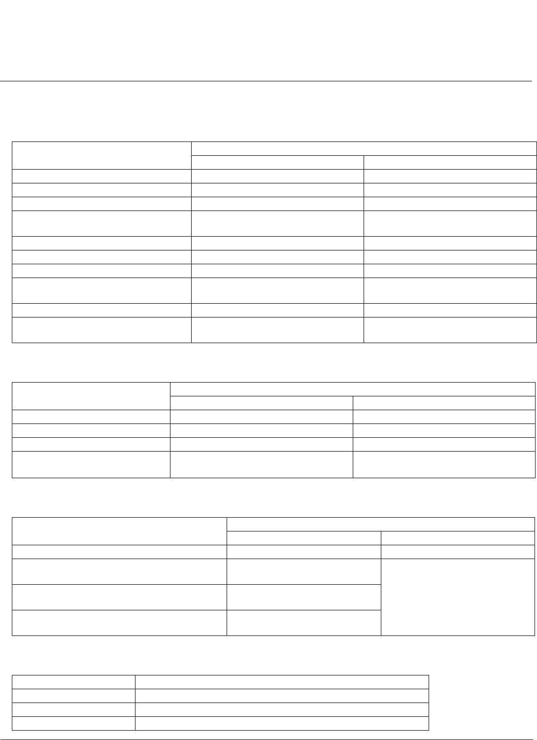
Technical Specifications Tsunami MP.16 3650 System User Guide
Hardware Specifications: Environmental Specifications
168
Hardware Specifications
Environmental Specifications
Power Specifications
Size and Weight Specifications
Integrated Antenna (SS only)
Feature Specification
Outdoor Radio Unit (BS/SS) Indoor Power Injector
Operating Temperature -40° to +60° C 0° to +40° C
Storage Temperature -55° to +85° C -20° to +85° C
Operating Altitude Up to 15,000 ft. Up to 15,000 ft.
Water Tightness IPx5 protection in accordance with IEC
60529 and UL50
IPx5 protection in accordance with IEC
60529 and UL50
Storage and Transit Altitude Up to 40,000 ft. Up to 40,000 ft.
Wind Up to 115 mph NA
Humidity Up to 100% Up to 95%, non-condensing
Dust IPx6 protection in accordance with IEC
60529
NA
Salt Immune NA
Transit and Vibration Per MIL-STD-810, methods 514.5 and
516
NA
Feature Specification
Outdoor Radio Unit (BS/SS) Indoor Power Injector
Input Voltage Range 42 to 60 VDC 90 to 260 VAC, 47 to 63 Hz
Output Voltage and Current NA 48 VDC up to 0.67 AMPs
Input Connector RJ45 3-conductor male
Power Consumption (Typical) BS: Less than 12 Watts
SS: Less than 10 Watts
Up to 32 Watts total power output
Feature Specification
Outdoor Radio Unit (BS/SS) Indoor Power Injector
Weight 5.3 lbs 2.7 lbs
Dimensions (Packaged) 14.57 x 13.70 x 8.19 in
(370 x 348 x 208 mm)
5.12 x 3.62 x 2.64 in
(130 x 92 x 67 mm)
Dimensions (Unpackaged: Model 3650 SS/BS) 10.5 x 10.5 x 3.25 in
(267 x 267 x 83 mm)
Dimensions (Unpackaged: Model 3650i SS) 12.6 x 12.6 x 3.5 in
(320 x 320 x 89 mm)
Feature Specification
Gain 18 dBi
Polarization Horizontal or vertical
Horizontal Beamwidth 18°

Technical Specifications Tsunami MP.16 3650 System User Guide
Hardware Specifications: Antenna Port
169
Antenna Port
Data Communication Port
Serial Configuration Port
Vertical Beamwidth 17°
Azimuth/Elevation Meets EN 302 085 TS2
Cross Polarization Meets EN 302 085 TS2
Return Loss 14 dB
Feature Specification
Connector N-Female, 50 Ohms
Return Loss, BS -15 dB, maximum
Return Loss, Antenna -10 dB, maximum
Feature Specification
Standard 10/100 Base-TX Ethernet, manual/auto negotiate, half/full duplex
Connector RJ45
Compliance 802.3, 802.3u, IPv4
Max Packet Size Up to 1600 bytes
Feature Specification
Connector RJ45
Feature Specification

123
Tsunami MP.16 3650 System User Guide
A
Command Line Interface
This chapter contains information on the following topics:
•CLI Overview
–Document Conventions
–Basic Functionality
–CLI Rules
–Commands
•Configuration from the Base Station
–System Parameters
–Base Station Parameters
–MAC Parameters
–Radio Parameters
–VLAN ID List
–Subscriber Station List
–Service Class Creation
–Subscriber Station Classes
–Service Flows
–Packet Identification Rules
–Logging Configuration
–Trap Host Parameters
–Management Interface Parameters
•Configuration from the Subscriber Station
–Subscriber Station Device Configuration
–Radio Configuration
–Logging Configuration
•Monitoring the BS and SS
–Software Version
–Network Status (SS only)
–Log Messages
–Base Station Statistics
–Subscriber Station Statistics

Command Line Interface Tsunami MP.16 3650 System User Guide
CLI Overview: Document Conventions
124
CLI Overview
Document Conventions
The following text conventions are used in this chapter:
• Computer prompts are shown as constant width type. For example: MP16>
NOTE: The root prompt is represented globally as “MP16.” Depending on your system’s name, your system may use
a different root prompt.
• Information that you input as shown is displayed in bold constant width type. For example:
MP16> set ipaddr 10.0.0.12
Basic Functionality
Navigation and Special Keys
The CLI supports the use of special key combinations and arrow keys for navigation. The supported special keys are
defined below:
Command History
You can access previously-executed commands in the history buffer. Commands in the history buffer can be accessed by
using the following special keys:
• Ctrl-P (previous line in history buffer)
• Ctrl-N (next line in history buffer)
• Up arrow (previous line in history buffer)
• Down arrow (next line in history buffer)
Command Line Completion
When you press the tab key while typing a command or argument at the prompt, the command or argument name will be
completed as the one that most closely matches what has been typed. Command or argument completion will only be
Key Combination Description
Backspace Delete previous character
Delete Delete next character
Ctrl–A Move cursor to beginning of line
Ctrl–E Move cursor to end of line
Ctrl–F Move cursor forward one character
Ctrl–B Move cursor back one character
Ctrl–D Delete the character the cursor is on
Ctrl–U Delete all text to the left of the cursor
Ctrl-K Delete to end of line
Ctrl-W Delete previous word
Ctrl-T Transpose previous character
Ctrl–P Go to the previous line in the history buffer (see Command History)
Ctrl–N Go to the next line in the history buffer (see Command History)
Tab Complete the command line (see Command Line Completion)
? List available commands (see Command Line Listing)

Command Line Interface Tsunami MP.16 3650 System User Guide
CLI Overview: CLI Rules
125
possible if there is no ambiguity, and if there is a match to what has been typed. If more than one command or argument
matches what has been typed, a list of possible matches will be displayed.
Command Line Listing
This command can be used in a number of ways to display available commands and parameters. The following table lists
each operation and provides a basic example.
CLI Rules
Parameter Groupings
For ease of configuring MP.16 products, the parameters have been logically grouped. Parameter tables for each group
contain the following information for each object:
• Name: Parameter, group, or table name
• Type: Data type
• Value: Value range and default value, if any
• Access: Access type
– R = Read Only (can only be viewed)
– RW = Read-Write (can be set or viewed)
– W = Write Only (for passwords and security-sensitive objects)
• Parameter: Parameter name as used in the CLI
Entering Values
Although the data type of a parameter may be “Integer”, in order for the CLI to interpret values correctly, enter the
provided alphanumeric value whenever possible.
Entering Strings
String objects are supported by MP.16 devices; a string delimiter is required for the strings to be interpreted correctly by
the command line parser. In this implementation, the single quote (‘) or double quote (“) character is to be used at the
beginning and at the end of any string that contains spaces. For example:
Rebooting
Some parameter values change only when the unit is rebooted. In these cases, the CLI warns you that a reboot is
required for the change to take effect.
Operation Basic Example
Display the Command List MP16>?
Display commands that start with specified letters MP16>c?
Display next possible parameters or commands MP16>configure ?
MP16>configure s?
set sysname ‘MP 16’ Quotes required
set sysname “MP 16” Quotes required
set sysname MP16 No quotes required

Command Line Interface Tsunami MP.16 3650 System User Guide
CLI Overview: Commands
126
Conventions
PIR Class, SF Class and SS Class Names
All the names are case-sensitive. When you create names with a combination of uppercase and lowercase characters,
you must use the same combination when configuring or deleting the PIR Class, SF Class, and SS Classes.
Interface Addressing
The following conventions are to be used during configuration for addressing the interfaces. These conventions apply to
both the SS and the BS.
• rf0: Wireless interface
• enet0: Ethernet interface
MAC Address Format
When specifying the MAC address in a command, the format can be one of the following:
• xx-xx-xx-xx-xx-xx
• xx:xx:xx:xx:xx:xx
Commands
Commands affect the unit’s behavior and allow you to configure parameters and tables. After entering commands (and
parameters/arguments, if any) press the Enter key to execute the Command Line.
The commands listed below are described in more detail in the following subsections:
•Add Command: Adds PIRs, SF Classes, Subscriber Stations, SS Classes, and VLAN IDs
•Configure Command: Allows configuration access to a group of parameters, packet identification rule, or service flow
•Delete Command: Deletes PIRs, SF Classes, Subscriber Stations, SS Classes, and VLAN IDs
•Download Command: Transfers files from the TFTP server to the unit
•Exit Command: Disconnects and closes the current CLI session
•Passwd Command: Changes the password used to access the CLI
•Reboot Command: Signals the unit to reboot after a specified number of seconds
•Reset Command: Resets the unit to factory default
•Set Command: Changes parameter values. This command is only available from the configure prompt; it not available
from the root prompt. (See Configure Command.)
•Show Command: Views parameter and statistical values
•Upload Command: Transfers files from the unit to the TFTP server
Add Command
Use the add command from the root prompt on the BS to add PIRs, Service Flows, Subscriber Station Classes,
authorized SSs, Syslog Servers, TFTP configuration information, Trap Hosts, and VLAN ID List entries.
Valid syntax for the add command is as follows:
Command Results
add pir <PIR name> Adds a Packet Identification Rules
add sfclass <SF Class name> Adds a Service Flow Class
add ssclass <SS Class name> Adds a Subscriber Station Class
add ss <SS MAC address> Adds an authorized Subscriber Station
add sysloghost <IP Address> Adds a Syslog Server to the Syslog Server List

Command Line Interface Tsunami MP.16 3650 System User Guide
CLI Overview: Commands
127
View the results of the add command from the root prompt as follows:
NOTE: Also see Service Class Creation for information on lists of pre-defined PIRs, SS Classes, and Service Flows.
Once PIRs, SF Classes, SS Classes, SSs, Syslog Hosts, TFTP hardware IDs, and Trap Hosts are added, use the
Configure Command to set and show parameters specific to each. As the VLAN table has no configurable parameters, it
is not executable with the configure command.
Configure Command
Use the configure command from the root prompt to access configuration parameters related to a particular group. For
example, executing configure with system allows the user to configure system parameters. The root prompt changes
based on the configure command, as follows:
MP16> configure system
MP16(system)>
To exit the configure prompt and return to the root prompt, use the exit command or press CTRL-Z.
Valid syntax for the configure command is as follows:
add tftpconf <Hardware ID> Adds a Secondary Management TFTP parameters for a specific
hardware ID
add traphost <IP Address> Adds a Trap Host to the Trap Host list
add vlantbl <VLAN ID> Adds a VLAN ID to the VLAN ID List
add vlanid <value> Adds a VLAN ID to an SS or SS Class configuration when VLAN mode
is set to Trunk. This command is only available from the SS or SS
Class configure prompts; it not available from the root prompt. See
Configure Command.
Command Results
show pir Displays a list of all Packet Identification Rules
show pir <PIR name> Displays all configured parameters for a particular PIR
show sfclass Displays a list of all Service Flow Classes
show sfclass <SF Class name> Displays all configured parameters for a particular Service Flow Class
show ssclass Displays a list of all SS Classes
show ssclass <SS Class name> Displays all configured parameters for a particular SS Class
show ss Displays a list of all authorized Subscriber Stations
show ss <SS MAC address> Displays all configured parameters for a particular authorized
Subscriber Station
show sysloghost Displays a list of all Syslog Servers
show sysloghost <IP Address> Displays all configured parameters of a particular Syslog Server
show tftpconf Displays a list of all configured hardware IDs
show tftpconf <Hardware ID> Displays all configured parameters of a particular configured hardware
ID
show traphost Displays a list of all configured Trap Hosts
show traphost <IP Address> Displays all configured parameters of a particular Trap Host
show vlantbl Displays a list of all VLAN IDs in the VLAN ID List.
show vlantbl <VLAN ID> Displays all configured parameters for a particular VLAN ID
Command Result
configure bs Access local Base Station parameters (Base Station only).
Command Results

Command Line Interface Tsunami MP.16 3650 System User Guide
CLI Overview: Commands
128
Delete Command
Use the delete command to delete configured PIRs, SF Classes, SS Classes, authorized SSs, and VLAN IDs.
Valid syntax for the delete command is as follows:
Download Command
The download command has different effects on the BS and the SS:
• On the SS: the download command is used to download an image from a specified TFTP server.
• On the BS, the download command is used to download an image file or a configuration file from a specified TFTP
server.
To transfer a file from the TFTP server to the unit:
download <TFTP Server IP Address> <path or filename> <file type>
where:
• <TFTP IP Address> is the IP address of the configured TFTP server
• <path or filename> is the filename or path and filename of file to be downloaded
configure log Access logging parameters (Base Station only).
configure mac Access Base Station MAC parameters (Base Station only).
configure pir <PIR name> Access Packet Identification Rule parameters (Base Station only).
configure radio Access Base Station radio parameters (Base Station only).
configure sfclass <Service
Flow Class Name>
Access Service Flow parameters (Base Station only).
configure ss <MAC Address> On the BS, access parameters for an authorized Subscriber Station.
On the SS, configure local SS parameters.
configure ssclass
<Subscriber Station Class
Name>
Access Subscriber Station class parameters (Base Station only).
configure syslog Enable or disable Syslog functionality (Base Station only).
configure sysloghost <IP
Address)
Configure the parameters of the specified Syslog server (Base Station only).
configure system Access configuration parameters related to the MP.16 system (Base Station
only).
configure tftpconf
<hardware ID>
Configure the Secondary Management TFTP parameters of the specified
hardware ID (Base Station only).
configure traphost <IP
Address>
Configure the parameters of the specified Trap host (Base Station only).
Command Results
delete pir <PIR name> Deletes a Packet Identification Rules (PIR)
delete sfclass <SF Class name> Deletes a Service Flow Class
delete ss <SS MAC address> Deletes an authorized Subscriber Station
delete ssclass <SS Class name> Deletes a Subscriber Station Class
delete sysloghost <IP Address) Configure the parameters of the specified Syslog server.
delete tftpconf <hardware ID> Delete a configured hardware ID for Secondary Management.
delete vlantbl <VLAN ID> Deletes a VLAN ID from the VLAN ID List
Command Result

Command Line Interface Tsunami MP.16 3650 System User Guide
CLI Overview: Commands
129
NOTE: If the file is located in the TFTP root directory, you do not need to enter a path. However, if the file is located in
a sub-level of the TFTP directory, enter the entire path, beginning with a back slash (\) and containing both the
path and the file name.
• <file type> is one of the following:
–config: configuration file
–image: compressed or FPGA image file
Examples:
>download 135.85.199.10 software_image001.bin image
>download 135.85.199.10 \config\software_image.bin config
Passwd Command
Use the passwd command to change the password used to access the CLI. Administrators can reset the password for
themselves or for users.
NOTE: If you are logged on as an administrator, you can change your own password or user-level passwords. If you are
logged on as a user, you can change only your own password.
To change the password, enter the following command:
MP16>passwd <old password> <new password> <new password>
For an administrator to change the user’s password, enter the following command:
MP16>passwd user <old password> <new password> <new password>
Enter the new password twice to ensure no mistake was made when specifying the new password. If you forget the CLI
password, there is no way to retrieve it from the unit and the CLI cannot be accessed. In this case, the unit must be reset
to factory defaults. The default password for the CLI is public.
The passwd command is available from the root prompt.
Reboot Command
Use the reboot command from the root prompt to signal the unit to reboot immediately.
MP16>reboot
Reset Command
Use the reset command from the root prompt to reset the unit to factory defaults or to reset statistics and logs.
Valid syntax for the reset command is as follows:
Set Command
Use the set command to change parameters in groups or tables. This command is only available from the configure
prompt; it not available from the root prompt. (See Configure Command.)
To set parameters, first access the configure prompt for the group to which the parameter belongs:
MP16>configure <group name>
Command Results
reset defaultcfg Resets the unit to factory default configuration.
reset stnstatreset Resets the station statistics.
reset log Resets the log.

Command Line Interface Tsunami MP.16 3650 System User Guide
CLI Overview: Commands
130
Then enter the set command from the configure prompt:
MP16 (group name)>set <parameter 1> <value 1> . . . <parameter N> <value N>
For example, to set the system name:
MP16>configure bs
MP16(bs)> set sysname MP16 location office
In the above example, the system name and location parameters are being modified.
NOTE: You may also set parameters in a single step by entering the configure and set commands in one command
line from the root prompt, as follows:
configure bs set sysname MP16 location office
Show Command
Use the show command from the root or the configure prompt to display the values of parameters or table entries, and to
view statistics and diagnostic tools.
The valid syntax for the show command is as follows:
For information on statistics and diagnostics viewable with the show command, see Monitoring the BS and SS.
Command Result Availability
show ? Displays a list of showable groups and
statistics.
BS and SS (root prompt and
configure prompt)
show Displays all configured parameters in a
group
BS and SS (configure prompt
only)
show <statistics, group, or
table name>
Displays all configured parameters in a
group or table, or shows statistics.
BS and SS (root prompt and
configure prompt)
show pir Displays a list of all PIRs. BS (root prompt)
show pir <PIR name> Displays configured parameters for a
particular PIR.
BS (root prompt)
show ssclass Displays a list of all SS Classes. BS (root prompt)
show ssclass <SS Class name> Displays configured parameters for a
particular SS Class.
BS (root prompt)
show sfclass Displays a list of all SF Classes. BS (root prompt)
show sfclass <SF Class name> Displays configured parameters for a
particular SF Class.
BS (root prompt)
show sysloghost Displays a list of all Syslog Servers BS and SS (root prompt)
show sysloghost <IP Address> Displays all configured parameters of a
particular Syslog Server
BS (root prompt)
show sysinvmgmt Displays hardware and software
components of the BS or SS
BS and SS (root prompt)
show tftpconf Displays a list of all configured hardware IDs BS (root prompt)
show tftpconf <Hardware ID> Displays all configured parameters of a
particular configured hardware ID
BS (root prompt)
show traphost Displays a list of all configured Trap Hosts BS (root prompt)
show traphost <IP Address> Displays all configured parameters of a
particular Trap Host
BS (root prompt)

Command Line Interface Tsunami MP.16 3650 System User Guide
CLI Overview: Commands
131
Upload Command
Use the upload command from the root prompt to transfer the configuration file from the Base Station to the TFTP
server.
To upload a configuration file from the BS to the TFTP server, use the following syntax:
MP16>upload <TFTP server address> <path or filename>
NOTE: If the file is located in the TFTP root directory, you do not need to enter a path. However, if the file is located in
a sub-level of the TFTP directory, enter the entire path, beginning with a back slash (\) and containing both the
path and the file name.
For example:
MP16>upload 135.85.199.10 config.bin
MP16>upload 135.85.199.10 \config\config.bin
Exit Command
Use the exit command as follows:
• From the root prompt: disconnect and close the CLI.
• From the configure prompt: return to the root prompt.
NOTE: Pressing CTRL-Z will also exit from a configuration prompt and return to the root-level prompt.

Command Line Interface Tsunami MP.16 3650 System User Guide
Configuration from the Base Station: System Parameters
132
Configuration from the Base Station
Log into the Base Station and use the add, delete, set, and show commands to set or view parameters associated with
the following groups/tables:
•System Parameters: Configure parameters affecting the MP.16 system as a whole. Parameters include Broadcast
Bandwidth Control and Default Gateway.
•Base Station Parameters: Configure Device, Base Station ID, Net Entry Mode, IP Addresses and Masks, Ethernet
Interface parameters, Bridging parameters, and VLAN Mode/Management ID parameters.
•MAC Parameters: Configure MAC parameters
•Radio Parameters: Configure Radio, Uplink Burst Profile, and Downlink Burst Profile parameters
•VLAN ID List
•Subscriber Station List
•Service Class Creation
–Subscriber Station Classes
–Service Flows
–Packet Identification Rules
•Logging Configuration
•Trap Host Parameters
•Management Interface Parameters
System Parameters
The parameters that affect the system as a whole are grouped under System. To configure the parameters under the
System group, you must get into the System configuration prompt, which is done by entering the following command:
MP16>configure system
The prompt will change to:
MP16(system)>
From the system configuration prompt, you can show or set parameters from the following groups:
•Broadcast Bandwidth Control
•Default Gateway
Broadcast Bandwidth Control
Default Gateway
Name Type Values Access Parameter
Broadcast Bandwidth
Control
Broadcast
Bandwidth
Control
TBD RW bcastbwctrl
Name Type Values Access Parameter
Gateway IP Address IP Address User defined RW dfltgateway

Command Line Interface Tsunami MP.16 3650 System User Guide
Configuration from the Base Station: Base Station Parameters
133
Base Station Parameters
Parameters that affect the Base Station only are grouped under Base Station. To configure the parameters under the
Base Station group, you must get into the Base Station configuration prompt, which is done by entering the following
command:
MP16>configure bs
The prompt will change to:
MP16(bs)>
From the bs configuration prompt, you can show or set parameters in the following categories:
•Base Station Device Parameters
•SS Authentication
•Networking
•VLAN Mode/Management ID
•Static IP Routes
Base Station Device Parameters
* These values will reset to default upon unit reboot.
SS Authentication
Networking
Name Type Values Access Parameter
Base Station ID MAC Address 48 bits
(default = 00:00:00:00:01)
RW bsid
Name Display String 1 – 255 alphanumeric characters RW sysname
Location Display String 1 – 255 alphanumeric characters RW location
Contact Name Display String 1 – 255 alphanumeric characters RW contact
Contact Email Display String 1 – 255 alphanumeric characters RW emailid
Contact Phone No. Display String 1 – 255 alphanumeric characters RW phone
Current Date and Time* Display String YYYY:MM:DD:HH:MM R/W* datetime*
Up Time Time Ticks 0 – 65535 R sysuptime
Name Type Values Access Parameter
Net Entry Mode Integer unrestricted (default)
int
ext
RW accessmode
Default SS Class Display String Any defined SS Class RW dfltss
Name Type Values Access Parameter
IP Address/Mask IP Address Valid IP address RW ipaddr
Maximum Multicast
Downlink
Integer Unlimited
8 - 8192 Kbps (in multiples of 8
kbps)
RW maxmcastdl
Maximum VLAN
Multicast Downlink
Integer Unlimited
8 - 8192 Kbps (in multiples of 8
kbps)
RW maxvlanmcastdl

Command Line Interface Tsunami MP.16 3650 System User Guide
Configuration from the Base Station: Base Station Parameters
134
To set the IP Address and Mask:
MP16>configure bs
MP16(bs)>set ipaddr <interface> <ipaddress> <mask>
where <interface> is either Ethernet (enet0) or Wireless (rf1).
To set the maximum multicast downlink or maximum VLAN multicast downlink:
MP16>configure bs
MP16(bs)>set maxmcastdl <value> or set maxvlanmcastdl <value>
To set the Ethernet speed:
MP16>configure bs
MP16(bs)>set speed enet0 <value>
VLAN Mode/Management ID
*When setting the BS to Trunk mode, you must also configure the Management VLAN ID that will be used to manage the BS. The Manage-
ment VLAN ID must be one of the VLAN IDs configured in the VLAN ID List. When you set the BS to Trunk mode, your CLI session will be
terminated (stop responding). Reconnect to the CLI through a VLAN switch continue BS configuration.
To set the VLAN mode to Transparent:
MP16>configure bs
MP16(bs)>set vlanmode transparent
To set the VLAN mode to Trunk:
MP16>configure bs
MP16(bs)>set vlanmode trunk mgmtvlan <VLAN ID> mgmtpriority <0-7>
Static IP Routes
NOTE: Static Routes are configured using the add command.
To add a static IP route:
MP16>configure bs
MP16(bs)>add iproute <network> <mask> <gateway>
Ethernet Speed Integer 10fullduplex
10halfduplex
100fullduplex
100halfduplex
Auto
RW speed
Repeating Mode Integer enable
disable (default)
RW repeating
Name Type Values Access Parameter
VLAN Mode* Integer transparent
trunk
RW vlanmode
Management VLAN ID* Integer 1 - 4095 RW mgmtvlan
Management Priority Integer 0-7 RW mgmtpriority
Name Type Values Access Parameter
Static IP Route — — — iproute
Name Type Values Access Parameter

Command Line Interface Tsunami MP.16 3650 System User Guide
Configuration from the Base Station: Base Station Parameters
135
where:
•<network> is the IP address of the destination network
•<mask> is the subnet mask of the destination network
•<gateway> is the IP address of the destination gateway
RADIUS Configuration
The following parameters may be viewed or configured:
To configure the RADIUS client on the BS, the IP address, shared secret, and status are required. All other parameters
are optional:
MP16>configure bs
MP16(bs)>set radius ipaddr <IP address> ssecret <password> status <enable/disable>
Name Type Values Access Parameter
Radius Group — R radius
RADIUS Server IP
Address
IP Address IP Address of RADIUS Server RW ipaddr
RADIUS Server
Destination Port Number
Integer 1000-65536 RW port
RADIUS Server Shared
Secret
Display String 1 - 64 characters RW ssecret
RADIUS Server
Response Time
Integer 1 - 10 (seconds) RW responsetm
Maximum
retransmissions to the
Server
Integer 0 - 4 RW maxretx
RADIUS Server Status Integer enable
disable
RW status

Command Line Interface Tsunami MP.16 3650 System User Guide
Configuration from the Base Station: MAC Parameters
136
MAC Parameters
The parameters that affect the BS MAC are grouped under mac. To configure the parameters under the MAC group, you
must get into the MAC configuration prompt by entering the following command:
MP16>configure mac
The prompt will change to:
MP16(mac)>
From the mac configuration prompt, you can show or set the following parameters:
*Time between transmission of DCD messages.
† Time between transmission of UCD messages.
‡ Time between Initial Ranging regions assigned by the BS.
**This parameter sets the downlink/uplink boundary of the TDD frame by setting the percentage of bandwidth allocated to the downlink. Set
the downlink percentage to a value between 10%-90% depending on the frame duration (see the following table). The remainder will be
allocated to the uplink.
Radio Parameters
The parameters that affect the BS radio are grouped under radio. To configure the parameters under the radio group,
you must get into the radio configuration prompt by entering the following command:
MP16>configure radio
Name Type Values Access Parameter
Frame Duration Integer 5
10 (default)
20
RW framedurcode
DCD Interval* Integer 100 - 10000 milliseconds
Default: 500
RW dcdinterval
UCD Interval† Integer 100 - 10000 milliseconds
Default: 500
RW ucdinterval
Initial Ranging Interval‡ Integer 20 - 2000 milliseconds
Default: 200
RW initrnginterval
AK Lifetime Integer 1800 - 604800 seconds
Default: 43200 seconds
RW aklifetime
TEK Lifetime Integer 1800 - 604800 seconds
Default: 43200 seconds
RW teklifetime
Frame Synchronization
Mode
Integer independent RW framesyncmode
Downlink Percentage** Integer 10% - 90% in steps of 1%
Default: 50%
RW dnlinkpercent
Cyclic Prefix Integer32 1/32
1/16
1/8
1/4
R cycprefix
GPS Sync Integer enable
disable
RW GPSSyncEnable
Frame Duration Minimum Downlink Percentage Maximum Downlink Percentage
5 ms 40% 50%
10 ms 20% 70%
20 ms 20% 70%

Command Line Interface Tsunami MP.16 3650 System User Guide
Configuration from the Base Station: Radio Parameters
137
The prompt will change to:
MP16(radio)>
From the radio configuration prompt, you can show or set parameters in the following categories:
•Radio Parameters
•Downlink Burst Profile Table
•Uplink Burst Profile Table
Radio Parameters
Downlink Burst Profile Table
You can enable/disable each modulation type in the Downlink Burst Profile Table.
*The modulation type is the index to this table. See example.
To enable/disable an entry in the Downlink Burst Profile Table:
MP16>set dnlinkburstprofile feccodetype <modulation type> status <enable/disable>
Uplink Burst Profile Table
You can enable/disable each modulation type in the Uplink Burst Profile Table.
Name Type Values Access Parameter
Channel Bandwidth Integer 3.5
7
RW chbandwidth
Center Frequency Integer 3650000 - 3675000
(in steps of 250)
Default: 36850365000
RW centerfreq
Transmit Power Integer 5 - 21 dBm (in steps of 1 dBm)
Default: 21 dBm
RW txpower
Downlink Burst Profile
Table
—See Downlink Burst Profile
Table
—See Downlink Burst
Profile Table
Uplink Modulation — See Uplink Burst Profile Table —See Uplink Burst
Profile Table
Name Type Values Access Parameter
Downlink Burst Profile
Table
Integer — R dnlinkburstprofile
Modulation Type* Integer bpsk_1_2
qpsk_1_2
qpsk_3_4
qam16_1_2
qam16_3_4
qam64_2_3
qam64_3_4
R feccodetype
Status Integer enable (default)
disable
RW status
Name Type Values Access Parameter
Uplink Burst Profile
Table
Integer — R uplinkburstprofile

Command Line Interface Tsunami MP.16 3650 System User Guide
Configuration from the Base Station: Radio Parameters
138
*The modulation type is the index to this table. See example.
To enable/disable an entry in the Uplink Burst Profile Table:
MP16>set uplinkburstprofile feccodetype <modulation type> status <enable/disable>
Modulation Type* Integer bpsk_1_2
qpsk_1_2
qpsk_3_4
qam16_1_2
qam16_3_4
qam64_2_3
qam64_3_4
R feccodetype
Status Integer enable (default)
disable
RW status
Name Type Values Access Parameter

Command Line Interface Tsunami MP.16 3650 System User Guide
Configuration from the Base Station: VLAN ID List
139
VLAN ID List
All VLAN IDs to be used by the BS and associated SSs must be stored in the VLAN ID List. Up to 256 individual VLAN
IDs may be stored in this list.
NOTE: See VLANs in the Base Station Configuration chapter for an overview of VLAN functionality in the MP.16 system.
Use the add and delete commands from the root prompt to add entries to or remove entries from the VLAN ID List
table:
MP16>add vlantbl <VLAN ID>
where <vlanid> is the ID of the VLAN you wish to add.
To view all VLAN IDs in the table:
MP16>show vlantbl
To delete entries in the vlan table,
MP16>delete vlantbl <vlanid> (deletes a particular VLAN)
MP16>delete vlantbl all (deletes all vlans)
Name Type Values Access Parameter
VLAN ID List Table N/A R vlantbl
VLAN ID Integer 1 – 4095 RW vlanid

Command Line Interface Tsunami MP.16 3650 System User Guide
Configuration from the Base Station: Subscriber Station List
140
Subscriber Station List
All SSs in the Subscriber Station List are authorized to join the network. Depending on the Net Entry mode of the Base
Station, this list is populated as follows:
• Unrestricted mode: SSs are automatically added to the Subscriber Station List upon registering with the network. The
default SS Class configured during SS Authentication is initially assigned to SSs.
• Internal authorization mode: Each SS must be manually added to the Subscriber Station List. An SS class is assigned
manually during this process.
CAUTION: In internal authorization mode, only SSs in the Subscriber Station List are authorized to join the network.
• External authorization mode: SSs are added to the Subscriber Station List automatically by the configured RADIUS
server. The RADIUS server assigns an SS class.
CAUTION: When changing to external authorization from any other authorization type, SSs currently in the SS List
must be manually deleted.
The administrator may optionally configure parameters of individual SSs on the list, including assigning an SS class,
overriding particular elements of an assigned SS Class, and resetting overridden parameters to their default states.
To view the entries in the SS List, enter the following command at the root prompt:
MP16>show ss
To add an SS MAC address to the SS List, use the add command as follows, at the root prompt:
MP16>add ss <SS MAC address>
To assign an SS Class, enter the following:
MP16>configure ss <SS MAC address>
MP16(SS MAC Address)>set ssclass <SS Class Name>
Additionally, you can configure parameters specific to the particular Subscriber Station from the ss configuration prompt.
These values will override the values of the associated SS Class.
For example, assume Subscriber Station 1 (SS1) is set to use SS Class 1 (SSCLASS1), and that SSCLASS1 has a
VLAN mode of “Trunk.” If you want SS1 to use SSCLASS1, but to use a VLAN mode of “Access,” you could override the
VLAN mode of the class by configuring the VLAN mode for SS1 only in the SS table.
If you do not configure any parameters specific to the SS, the SS Class parameters will be applied.
You may also reset the overrides to the original Class parameters.
To view all configurable parameters for the SS, enter the following command at the SS prompt:
MP16(SS MAC Address)>set ?
To view all configured parameters for the SS, enter the following command at the SS prompt:
MP16(SS MAC Address)>show
The following parameters can be configured for the SS:
Name Type Values Access Parameter
MAC Address MAC Address — R macaddr
SS Class DisplayString Alphanumeric RW ssclass

Command Line Interface Tsunami MP.16 3650 System User Guide
Configuration from the Base Station: Subscriber Station List
141
* Use “inherited” to use the VLAN parameters associated with the assigned SS Class.
Transparent Mode
To set the VLAN mode for the SS to Transparent:
MP16(SS MAC Address)>set vlanmode transparent
Access Mode
To configure the SS for Access mode, set the mode the Access, specify an allowed VLAN ID, and set the management
priority. The VLAN ID will also be the management ID.
MP16(SS MAC Address)>set vlanmode access vlanid <1 -4095> priority <0 - 7>
MP16(SS MAC Address)>add vlanid <1 - 4095>
Uplink Modulation Type Integer adaptive
bpsk_1_2
qpsk_1_2
qpsk_3_4
qam16_1_2
qam16_3_4
qam64_2_3
qam64_3_4
RW upmodtype
Downlink Modulation
Type
Integer adaptive
bpsk_1_2
qpsk_1_2
qpsk_3_4
qam16_1_2
qam16_3_4
qam64_2_3
qam64_3_4
RW downmodtype
VLAN Mode Integer transparent (default)
access
trunk
mixed
inherited*
RW vlanmode
VLAN ID (used in Access
Mode or Trunk mode)
(see Access Mode and
Trunk Mode)
Integer 1 – 4095 RW vlanid
Management Priority
(used in Access mode)
(see Access Mode)
Integer 0 – 7 RW priority
Access ID (used in
Mixed mode) (See Mixed
Mode)
Integer 1 – 4095 RW accessid
Access Priority ((used in
Mixed mode) (See
Mixed Mode)
Integer 0 – 7 RW accesspriority
Trunk ID (used in Mixed
mode) (See Mixed
Mode)
Integer 1 – 4095 RW trunkid
Name Type Values Access Parameter

Command Line Interface Tsunami MP.16 3650 System User Guide
Configuration from the Base Station: Subscriber Station List
142
Trunk Mode
To configure the SS for Trunk mode, set the mode the Trunk and specify a VLAN management ID. Then use the add and
delete commands to configure a group of allowed VLAN IDs. This group may contain up to 16 VLAN IDs.
MP16(SS MAC Address)>set vlanmode trunk vlanid <Management VLAN ID>
MP16(SS MAC Address)>add vlanid <1 - 4095>
.
.
.
MP16(SS MAC Address)>add vlanid <1 - 4095>
Mixed Mode
To configure the SS for Mixed mode, set the mode the Mixed and specify a VLAN Access ID and a VLAN Trunk ID to be
used for management, as well as an Access priority. Then use the add and delete commands to configure a group of
allowed VLAN IDs. This group may contain up to 16 VLAN IDs.
MP16(SS MAC Address)>set vlanmode mixed accessid <Management VLAN ID> trunkid
<Management VLAN ID> access priority <0-7>
MP16(SS MAC Address)>add vlanid <1 - 4095>
.
.
.
MP16(SS MAC Address)>add vlanid <1 - 4095>

Command Line Interface Tsunami MP.16 3650 System User Guide
Configuration from the Base Station: Service Class Creation
143
Service Class Creation
Service classes, also called Subscriber Station Classes (SS Classes), are comprised of uplink and downlink Service
Flows, each of which has specific QoS settings. Traffic is directed to Service Flows through the application of Packet
Identification Rules. See Wireless Communication and Service Classes for a brief overview of SS Classes and Service
Class Creation for a more detailed discussion of SS Class creation.
The MP.16 system comes supplied with pre-defined SS Classes, Service Flows, and PIRs. In addition, you can
customize the predefined SS Classes, Service Flows, and PIRs, or create new ones that uniquely serve the needs of
your network environment.
While SS Classes use Service Flows and PIRs to direct traffic, each of these can be configured independently. That is, if
you want to create a new SS Class that uses a new PIR or Service Flow, you must first define the new PIR or Service
Flow, and then define the new SS Class that uses them. Alternatively, you may create a new SS Class that uses
pre-defined PIRs and Service Flows, or you create a new PIR or Service flow to be used with a pre-defined SS class.
Each element of the class is defined separately from the others.
See the following sections for instructions:
•Subscriber Station Classes: Create and configure new Subscriber Station classes; edit pre-defined SS Classes.
•Service Flows: Create and configure new service flows; edit pre-defined Service Flows.
•Packet Identification Rules: Create and configure new PIRs; edit pre-defined PIRs.
Subscriber Station Classes
You may create, modify, and delete up to 64 SS Classes, including those that are pre-defined. If the Base Station is reset
to factory defaults, the original values of the parameters for the pre-defined Subscriber Station classes are restored.
To create an new SS Class, enter the following command at the root prompt:
MP16 >add ssclass <name of SS class>
To view a list of all SS classes, enter the following from the root prompt:
MP16>show ssclass
To view the configuration of an SS Class, enter the following from the root prompt:
MP16>show ssclass <SS Class Name>
To delete an SS Class, enter the following from the root prompt:
MP16>delete ssclass <SS Class Name>
To configure the parameters of a particular Subscriber Station class, you must access the ssclass configuration prompt.
Enter the following at the root prompt:
MP16>configure ssclass <name of SS class>
The prompt will change to:
MP16(SS Class name)>
To view the configuration of the current SS Class, enter the following from the ssclass configuration prompt:
MP16>show
From the ssclass configuration prompt, you can add, set, and show parameters as described in the following sections:
•Adding Service Flows to an SS Class
•Associating PIRs with Added Service Flows
•Configuring SS Class VLAN Parameters
See SS Class Creation Example for a step-by-step configuration example.

Command Line Interface Tsunami MP.16 3650 System User Guide
Configuration from the Base Station: Service Class Creation
144
Subscriber Station Class Parameters
Adding Service Flows to an SS Class
You can add up to 16 Service Flows to the Subscriber Station Class.
To add a service flow for a Subscriber Station class:
MP16(SS Class name)>add sfclass <service flow class name> <type>
where <type> is one of the following:
•IPv4 ENET: Use this type when associated PIRs use at least one IP classifier and no VLAN classifiers. Ethernet
classifiers are optional.
•IPv4 VLAN: Use this type when associated PIRs use at least one IP classifier and one VLAN classifier.
•ENET 802.3: Use this type when associated PIRs use only Ethernet classifiers.
•VLAN 802.1Q: Use this type when associated PIRs use only VLAN classifiers.
NOTE: If the Service Flow has not yet been defined, or if the Service Flow is already added to the SS class, an error
message will be displayed.
Associating PIRs with Added Service Flows
For each service flow, you can associate up to 16 PIRs.
To add a PIR to a Service Flow within the context of a particular Subscriber Station class:
MP16(SS Class name)>add pir <SF Class name> <PIR name> <priority>
where <priority> is a value between 1 and 255.
NOTE: If the PIR has not yet been defined, or if the Service Flow already has the maximum number of PIRs added to it,
an error message will be displayed.
Name Type Values Access Parameter
VLAN Mode Integer transparent (default)
access
trunk
mixed
RW vlanmode
VLAN ID (used in Access
Mode or Trunk mode)
(see Access Mode and
Trunk Mode)
Integer 1 – 4095 RW vlanid
Management Priority
(used in Access mode)
(see Access Mode)
Integer 0 – 7 RW priority
Access ID (used in
Mixed mode) (See Mixed
Mode)
Integer 1 – 4095 RW accessid
Access Priority ((used in
Mixed mode) (See
Mixed Mode)
Integer 0 – 7 RW accesspriority
Trunk ID (used in Mixed
mode) (See Mixed
Mode)
Integer 1 – 4095 RW trunkid

Command Line Interface Tsunami MP.16 3650 System User Guide
Configuration from the Base Station: Service Class Creation
145
Configuring SS Class VLAN Parameters
For each SS Class, you can set the VLAN mode and, depending the mode, associated VLAN parameters. See the
following:
•Configuring the SS Class for Transparent Mode
•Configuring the SS Class for Access Mode
•Configuring the SS Class for Trunk Mode
•Configuring the SS Class for Mixed Mode
Configuring the SS Class for Transparent Mode
If the BS VLAN mode is set to Transparent, you can set the VLAN mode of the SS Class to either Transparent or Access.
To set the VLAN mode to Transparent, enter the following:
MP16(SS Class name)>set vlanmode transparent
With the VLAN mode set to Transparent, no further VLAN parameters need to be set.
Configuring the SS Class for Access Mode
If the BS VLAN mode is set to Transparent, you can set the VLAN mode of the SS Class to either Transparent (see
above) or Access. If you set the VLAN mode to Access, an allowed VLAN ID, and set the management priority. The
VLAN ID will also be the management ID. The VLAN ID must be taken from the VLAN ID List.
MP16(SS Class Name)> set vlanmode access vlanid <value> priority <value>
Configuring the SS Class for Trunk Mode
If the BS VLAN mode is set to Trunk, you can set the VLAN mode of the SS Class to either Access (see above), Trunk
(described here) or Mixed (see below). When setting the VLAN mode to Trunk, you must also specify a VLAN ID that will
have management access. This VLAN ID must be one of the VLAN IDs configured in the VLAN ID List.
MP16(SSCLASS1)>set vlanmode trunk vlanid <value>
With the VLAN mode to Trunk, you may add up to 16 entries to the list of allowed VLAN IDs. The allowed VLAN IDs must
be from the VLAN ID List.
MP16(SSCLASS1)>add vlanid <value>
.
.
.
MP16(SSCLASS1)>add vlanid <value>
Configuring the SS Class for Mixed Mode
If the BS VLAN mode is set to Trunk, you can set the VLAN mode of the SS Class to either Access (see above), Trunk
(see above) or Mixed (described here). When setting the VLAN mode to Access, you must also specify a VLAN Access
ID and a VLAN Trunk ID to be used for management, as well as an Access priority. These VLAN IDs must be from the list
of VLAN IDs configured in the VLAN ID List.
MP16(SS MAC Address)>set vlanmode mixed accessid <Management VLAN ID> trunkid
<Management VLAN ID> access priority <0-7>
With the VLAN mode to Mixed, you may add up to 16 entries to the list of allowed VLAN IDs. The allowed VLAN IDs must
be from the VLAN ID List.
MP16(SSCLASS1)>add vlanid <value>
.
.
.

Command Line Interface Tsunami MP.16 3650 System User Guide
Configuration from the Base Station: Service Class Creation
146
MP16(SSCLASS1)>add vlanid <value>
SS Class Creation Example
The following example assumes that you are creating a new SS Class using pre-defined Service Flows and PIRs.
Step 1: Add New SS Class
In this step, you are creating a new SS Class, called SSCLASS1, and entering the configuration prompt for that new
Class.
MP16>add ssclass SSCLASS1
MP16>configure SSCLASS1
MP16(SSCLASS1)>
From the configure prompt for the new SS Class, you can add Service Flows to the class.
Step 2: Add Service Flows
In this step, you are two uplink and two downlink Service Flows with associated Service Flow types.
MP16(SSCLASS1)>add sfclass UL-SFCLASS1 ipv4_enet
MP16(SSCLASS1)>add sfclass UL-SFCLASS2 vlan_802_1q
MP16(SSCLASS1)>add sfclass DL-SFCLASS1 ipv4_enet
MP16(SSCLASS1)>add sfclass DL-SFCLASS2 vlan_802_1q
NOTE: If the Service Flow has not yet been defined, or if the Service Flow is already added to the SS class, an error
message will be displayed.
NOTE: To see a list of available SFs, return to the root prompt by pressing CTRL-Z, and enter show sfclass.
Step 3: Associate PIRs with Service Flows
In this step, you must associate PIRs with the added Service Flows.
MP16(SSCLASS1)>add pir UL-SFCLASS1 PIR1 1
Above, you added PIR1 to UL-SFCLASS1 with a priority of 1. Now you will add more PIRs to Service Flows.
MP16(SSCLASS1)>add pir UL-SFCLASS1 PIR3 2
MP16(SSCLASS1)>add pir UL-SFCLASS1 PIR7 5
MP16(SSCLASS1)>add pir UL-SFCLASS2 PIR16 9
MP16(SSCLASS1)>add pir DL-SFCLASS1 PIR6 3
MP16(SSCLASS1)>add pir DL-SFCLASS1 PIR4 1
NOTE: If the PIR has not yet been defined, or if the Service Flow already has the maximum number of PIRs added to it,
an error message will be displayed.
NOTE: To see a list of available PIRs, return to the root prompt by pressing CTRL-Z, and enter show pir.
You have now added PIRs to Service Flows as follows:
• UL-SFCLASS1 has three PIRs associated with it: PIR1, PIR3, and PIR7
• UL-SFCLASS2 has one PIR, PIR16, associated with it.
• DL-SFCLASS1 has one PIR, PIR6, associated with it.
• DL-SFCLASS2 has one PIR, PIR4, associated with it
Step 4: Configure SS Class VLAN Parameters
Option A: Configuring SS Class for Transparent Mode
If the BS VLAN mode is set to Transparent, you can set the VLAN mode of the SS Class to Transparent if you do not
want to restrict access to the network.

Command Line Interface Tsunami MP.16 3650 System User Guide
Configuration from the Base Station: Service Class Creation
147
MP16(SSCLASS1)>set vlanmode transparent
No further parameters need to be set.
Option B: Configuring SS Class for Access Mode
If the BS VLAN mode is set to Transparent, you can set the VLAN mode of the SS Class to Access to restrict access to
the network. When you select Access, you must also select a VLAN ID with management access and set the
management priority. The Management VLAN ID must be taken from the VLAN ID List configured from the root prompt or
from the Configuration > Networking > VLAN ID List page in the Web interface.
MP16(SSCLASS1)>set vlanmode access vlanid 25 priority 1
Above, you selected VLAN ID 25 as the Management VLAN ID for the SS Class, and you set the Management Priority to
1.
Option C: Configuring SS Class for Trunk Mode
If the BS VLAN mode is set to Trunk, you can set the VLAN mode of the SS Class Trunk to allow access by multiple
VLANs. When you select Trunk, you must also select a VLAN ID for management access.
MP16(SSCLASS1)>set vlanmode trunk vlanid 1
With the VLAN mode to Trunk, you can add up to 16 entries to the list of allowed VLAN IDs. The VLAN IDs must be taken
from the VLAN ID List configured from the root prompt or from the Configuration > Networking > VLAN ID List page in
the Web UI.
MP16(SSCLASS1)>add vlanid 15
MP16(SSCLASS1)>add vlanid 25
MP16(SSCLASS1)>add vlanid 100
Above, you selected VLAN ID 1 as the Management VLAN ID, and added VLAN IDs 15, 25, and 100 to the list of allowed
VLAN IDs.
Option D: Configuring SS Class for Mixed Mode
If the BS VLAN mode is set to Trunk, you can set the VLAN mode of the SS Class to Mixed to allow both tagged and
untagged frames to access the network. When you select Mixed mode, you must also specify a VLAN Access ID and a
VLAN Trunk ID to be used for management, as well as an Access priority.
MP16(SSCLASS1)>set vlanmode access accessid 1 access priority 7 trunkid 12
With the VLAN mode to Mixed, you can add up to 16 entries to the list of allowed VLAN IDs. The VLAN IDs must be taken
from the VLAN ID List configured from the root prompt or from the Configuration > Networking > VLAN ID List page in
the Web UI.
MP16(SSCLASS1)>add vlanid 15
MP16(SSCLASS1)>add vlanid 25
MP16(SSCLASS1)>add vlanid 100
Above, you selected VLAN ID 1 as the Access Management VLAN ID and VLAN ID 12 as the Trunk Management VLAN
ID. You then added VLAN IDs 15, 25, and 100 to the list of allowed VLAN IDs.
Step 5: View SS Class Configuration
In this step, you will review the SS Class configuration you just completed:
MP16(SSCLASS1)>show

Command Line Interface Tsunami MP.16 3650 System User Guide
Configuration from the Base Station: Service Class Creation
148
Service Flows
You can create, modify, and delete up to 256 Service Flow classes, including those that are pre-defined on the Base
Station. If the Base Station is reset to factory defaults, the original values of the parameters for the pre-defined service
flow classes are restored.
To create an new SF Class, enter the following command at the root prompt:
MP16 >add sfclass <SF Class name>
To view a list of all SF Classes, enter the following from the root prompt:
MP16>show sfclass
To view the configuration of an SF Class, enter the following from the root prompt:
MP16>show sfclass <SF Class name>
To delete an SF, enter the following from the root prompt:
MP16>delete sfclass <SF Class name>
To configure the parameters of a particular SF Class, you must access the sfclass configuration prompt. Enter the
following at the root prompt:
MP16>configure sfclass <SF Class name>
The prompt will change to:
MP16(SF Class name)>
To view the configuration of the current SF Class, enter the following from the sfclass configuration prompt:
MP16>show
From the sfclass prompt, you can show or set parameters described below.
Service Flow Class Parameters
QoS Scheduling Types
Four QoS scheduling types are available. After selecting a scheduling type, set the associated parameters, as follows:
•UGS: The following QoS parameters are configurable (see table above):
– Maximum sustained information rate
Name Type Values Access Parameter
Service Flow Class ID Integer NA R sfclassid
Scheduling Type (see
QoS Scheduling Types)
DisplayString32 ugs
rtps
nrtps (default)
be
RW schedtype
Service Flow Direction Integer uplink
downlink
RW direction
Maximum Sustained
Data Rate
Integer 8 – 8192 kbps (in steps of 8
kbps)
RW maxsusdatrt
Minimum Reserved
Traffic Rate
Integer 8 – 8192 kbps in steps of 8 kbps
(default = 0)
RW minresdatrt
Maximum Latency Integer 5 – 100 ms (in steps of 5 ms) RW maxslat
Tolerable Jitter Integer 5 – 100 ms (in steps of 5 ms) RW toljtr
Traffic Priority Integer 0 – 7 RW trafpriority

Command Line Interface Tsunami MP.16 3650 System User Guide
Configuration from the Base Station: Service Class Creation
149
– Maximum latency
– Tolerable jitter
•rtPS: The following QoS parameters are configurable (see table above):
– Maximum sustained information rate
– Minimum reserved traffic rate
– Maximum latency
•nrtPS: The following QoS parameters are configurable (see table above):
– Maximum sustained information rate (MIR)
– Minimum reserved traffic rate
– Traffic priority
•BE: The following QoS parameters are configurable (see table above):
– Maximum sustained information rate (MIR)
– Traffic priority
Packet Identification Rules
You can create, modify, and delete up to 512 Packet Identification Rules (PIRs), including those that are pre-defined on
the Base Station. If the Base Station is reset to factory defaults, the original values of the parameters for the pre-defined
PIRs are restored.
To create an new PIR, enter the following command at the root prompt:
MP16 >add pir <PIR name>
To view a list of all PIRs, enter the following from the root prompt:
MP16>show pir
To view the configuration of a PIR, enter the following from the root prompt:
MP16>show pir <PIR name>
To delete a PIR, enter the following from the root prompt:
MP16>delete PIR <PIR name>
To configure the parameters of a particular PIR, you must access the pir configuration prompt. Enter the following at the
root prompt:
MP16>configure pir <PIR name>
The prompt will change to:
MP16(PIR name)>
To view the configuration of the current PIR, enter the following from the pir configuration prompt:
MP16>show
From the pir prompt, use the add command to configure parameters as described in the following sections.
PIR Parameters
NOTE: PIR parameters are configured using the add command.
Name Type Values Access Parameter
Blocked Integer enable
disable (default)
See Blocked (blocked)
RW blocked

Command Line Interface Tsunami MP.16 3650 System User Guide
Configuration from the Base Station: Service Class Creation
150
Blocked (blocked)
When the blocked parameter is enabled, packets matching the classifiers configured below are blocked. When disabled,
packets matching the classifiers configured below are allowed. Use the following syntax:
MP16(PIR Name)>add blocked <enable/disable>
IP Type of Service (iptos)
The IP Type of Service parameters are under the group iptos. To add IP Type of Service entries, use the following
syntax:
MP16(PIR Name)>add iptos <iptos low value> <iptos high value> <iptos mask value>
where all values are between 0 and 255.
Execute a show command to view the value of the IPTOS parameters:
MP16(PIR Name)>show iptos
To delete iptos entries:
MP16(PIR Name)>delete iptos
IP Protocol List (ipproto)
The IP Protocol list is grouped under ipproto. Up to 16 entries can be added to this list. To add entries:
MP16(PIR Name)>add ipproto <value>
where <value> is a number between 1 – 255.
IP Type of Service Integer See IP Type of Service
(iptos)
RW iptos
IP Protocol List Table See IP Protocol List
(ipproto)
RW ipproto
IP Source & Mask List Table See IP Source Address
and Mask List (scrcipaddr)
RW srcipaddr
Ethernet Source MAC and
Mask
Table See Ethernet Source MAC
Address and Mask
(srcmacaddr)
RW srcmacaddr
Protocol Source Port Range Table See Protocol Source Port
Range (srcport)
RW srcport
IP Destination & Mask List Table See IP Destination
Address and Mask List
(destippaddr)
RW destipaddr
Ethernet Destination MAC and
Mask
Table See Ethernet Destination
MAC Address and Mask
(destmacaddr)
RW destmacaddr
Protocol Destination Port
Range
Table See Protocol Destination
Port Range (destport)
RW destport
Ethernet Type/Value Table See Ethernet Type/Value
(ethertype)
RW ethertype
Ethernet Priority Integer See Ethernet Priority
(ethernetpriority)
RW ethernetpriority
VLAN ID Integer See VLAN ID (vlanid) RW vlanid
Name Type Values Access Parameter

Command Line Interface Tsunami MP.16 3650 System User Guide
Configuration from the Base Station: Service Class Creation
151
Execute a show command to view the entries in the IP Protocol List:
MP16(PIR Name)>show ipproto
To delete a single IP Protocol List entry:
MP16(PIR Name)>delete ipproto <index>
To delete all entries:
MP16(PIR Name)>delete ipproto all
IP Source Address and Mask List (scrcipaddr)
The IP source address and mask parameters are under the group srcipaddr. Up to 16 entries can be added to this list.
To add entries, use the following syntax:
MP16(PIR Name)>add scripaddr <source IP address> <mask>
Execute a show command to view the entries in the IP Source Address and Mask List, with index numbers:
MP16(PIR Name)>show srcipaddr
To delete an entry in the table:
MP16(PIR Name)>delete srcipaddr <index>
To delete all entries in the table
Ethernet Source MAC Address and Mask (srcmacaddr)
The Ethernet source MAC address and mask parameters are under the group srcmacaddr. To add an entry:
MP16(PIR Name)>add srcmacaddr <Ethernet destination MAC address> <mask>
Execute a show command to view Ethernet Source MAC and Mask parameters, with index numbers:
MP16(PIR Name)>show srcmacaddr
To delete an entry in the table:
MP16(PIR Name)>delete srcmacaddr <index>
To delete all entries in the table
MP16(PIR Name)>delete srcmacaddr all
Protocol Source Port Range (srcport)
This range may only be configured if TCP and/or UDP are included in the IP Protocol list. The IP protocol source port
start and end parameters are under the group srcport. Up to 16 entries can be added to this list. To add entries, use the
following syntax:
MP16(PIR Name)>add srcport <start port value> <end port value>
where:
<start port value> is the low-end inclusive range of TCP/UDP source port numbers to which a packet is compared and
<end port value> is the high-end inclusive range of TCP/UDP source port numbers to which a packet is compared. The
range is between 0 – 65535.
Execute a show command to view the entries in the Protocol Source Port range, with index numbers:
MP16(PIR Name)>show srcport
To delete an entry in the table:
MP16(PIR Name)>delete srcport <index>

Command Line Interface Tsunami MP.16 3650 System User Guide
Configuration from the Base Station: Service Class Creation
152
To delete all entries in the table:
MP16(PIR Name)>delete srcport all
MP16(PIR Name)>delete srcipaddr all
IP Destination Address and Mask List (destippaddr)
The IP source address and mask parameters are under the group destipaddr. Up to 16 entries can be added to this list.
To add entries, use the following syntax:
MP16(PIR Name)>add destipaddr <destination IP address> <mask>
Execute a show command to view the entries in the IP Destination Address and Mask List, with index numbers:
MP16(PIR Name)>show destipaddr
To delete an entry in the table:
MP16(PIR Name)>delete destipaddr <index>
To delete all entries in the table
MP16(PIR Name)>delete destipaddr all
Ethernet Destination MAC Address and Mask (destmacaddr)
The Ethernet source MAC address and mask parameters are under the group srcmacaddr. To add an entry:
MP16(PIR name)> add destmacaddr <Ethernet source MAC address> <mask>
Execute a show command to view Ethernet Destination MAC and Mask parameters, with index numbers:
MP16(PIR Name)>show destmacaddr
To delete an entry in the table:
MP16(PIR Name)>delete destmacaddr <index>
To delete all entries in the table
MP16(PIR Name)>delete destmacaddr all
Protocol Destination Port Range (destport)
This range may only be configured if TCP and/or UDP are included in the IP Protocol list. The IP protocol source port
start and end parameters are under the group destport. Administrators can add up to 16 entries in this list. To add an
entry, use the following syntax:
MP16(PIR Name)>add destport <start port value> <end port value>
where <start port value> is the low-end inclusive range of TCP/UDP source port numbers to which a packet is compared,
and <end port value> is the high-end inclusive range of TCP/UDP source port numbers to which a packet is compared.
The range is between 0 – 65535.
Execute a show command to view the entries in the Protocol Destination Port range, with index numbers:
MP16(PIR Name)>show destport
To delete an entry in the table:
MP16(PIR Name)>delete destport <index>
To delete all entries in the table
MP16(PIR Name)>delete destport all

Command Line Interface Tsunami MP.16 3650 System User Guide
Configuration from the Base Station: Logging Configuration
153
Ethernet Type/Value (ethertype)
The Ethernet Type parameter designates the Ethernet type on which the filtering is to be done. To add an Ethernet type
entry:
MP16(PIR Name)>add ethertype <value> <Ethernet Protocol Type>
where <value> is dix_snap or dsap, and <Ethernet Protocol Type> is a 16-bit value if dix_snap is selected, and an 8-bit
value if dsap is selected. Ethernet protocol type can be one of the following:
• 0200 (Xerox PUP)
• 6001 (DEZ MOP)
• 8005 (HP Probe)
• 809B (AppleTalk)
Execute a show command to view Ethernet type:
MP16(PIR Name)>show ethertype
To delete the Ethernet type:
MP16(PIR Name)>delete ethertype
Ethernet Priority (ethernetpriority)
The Ethernet priority parameters are under the group ethernetpriority. To add an entry:
MP16(PIR Name)>add ethernetpriority <Ethernet priority low> <Ethernet priority high>
where <ethernet priority low> and <ethernet priority high> are values in the range 0 - 7.
Execute a show command to view Ethernet priority:
MP16(PIR Name)>show ethernetpriority
To delete the Ethernet priority:
MP16(PIR Name)>delete ethernetpriority
VLAN ID (vlanid)
The VLAN ID designates the VLAN on which the filtering is to be done. To add a VLAN ID:
MP16(PIR Name)>add vlanid <value>
where <value> is a number between 0 – 4095 (0 = unused).
To delete the VLAN ID:
MP16(PIR Name)>delete vlandid
Logging Configuration
To configure logging related parameters, enter the following command at the root prompt:
MP16>configure log
The prompt will change to:
MP16(log)>
From the log configuration prompt, you can set or show the following logging configuration parameters:

Command Line Interface Tsunami MP.16 3650 System User Guide
Configuration from the Base Station: Trap Host Parameters
154
Trap Host Parameters
To configure the Trap Host parameters, you must first add a Trap Host. Enter the following command from the root
prompt:
MP16>add traphost <IP Address>
To configure the added Trap Host, enter the following command from the root prompt:
MP16>configure traphost <IP Address>
The prompt will change to:
MP16(trap host IP Address)>
Management Interface Parameters
To configure the management interface parameters, enter the following command from the root prompt:
MP16> configure mgmtinterface
The prompt will change to:
MP16(configure-mgmtinterface)>
Name Type Values Parameter
Volatile Log Status Integer enable
disable
vlogstatus
Non-Volatile Log Status Integer enable
disable
nvlogstatus
Volatile Log Filter Level Integer none
emergency
alert
critical
error
warning
notice
informational
debug
all
vloglevel
Non-Volatile Log Filter Level Integer none
emergency
alert
critical
error
warning
notice
informational
debug
all
nvloglevel
Name Type Values Access Parameter
IP Address IP Address User defined RW —
Password DisplayString User defined W password
Status Integer enable
disable (default)
RW status
Comment DisplayString User defined RW comment

Command Line Interface Tsunami MP.16 3650 System User Guide
Configuration from the Base Station: Management Interface Parameters
155
Name Type Values Access Parameter
SNMP Enable/Disable Integer enable (default)
disable
RW snmp

Command Line Interface Tsunami MP.16 3650 System User Guide
Configuration from the Subscriber Station: Subscriber Station Device Configuration
156
Configuration from the Subscriber Station
Log into the Subscriber Station and use the configure, delete, set, and show commands to set or view local SS
parameters. See the following sections:
•Subscriber Station Device Configuration
•Radio Configuration
•Logging Configuration
Subscriber Station Device Configuration
To configure the individual SS parameters, enter the following command from the root prompt:
MP16>configure ss
The prompt will change to:
MP16(ss)>
From the ss prompt, you can show or set parameters in the following groups:
•Device Parameters
•IP Addresses/Masks
Device Parameters
IP Addresses/Masks
To set the IP Address and Mask:
MP16(ss)>set ipaddr <interface> <ipaddress> <mask>
where <interface> is Ethernet (enet0).
To set the Default Gateway:
MP16(ss)>set dfltgw <ipaddress>
Radio Configuration
To configure the radio parameters for an SS, enter the following command from the root prompt:
Name Type Values Access Parameter
Name DisplayString 1 – 255 alphanumeric
characters
RW sysname
Location DisplayString 1 – 255 alphanumeric
characters
RW location
Contact Name DisplayString 1 – 255 Alphanumeric
characters
RW contact
Contact Email DisplayString 1 – 255 alphanumeric
characters
RW emailid
Contact Phone Number DisplayString 1 – 255 alphanumeric
characters
RW phone
Name Type Values Access Parameter
IP Address IP Address Valid IP address RW ipaddr
Default Gateway IP Address — RW dfltgw

Command Line Interface Tsunami MP.16 3650 System User Guide
Configuration from the Subscriber Station: Logging Configuration
157
MP16>configure radio
The prompt will change to:
MP16(radio)>
From the radio prompt, you can show or set the following parameters:
Logging Configuration
To configure logging related parameters, enter the following command at the root prompt:
MP16>configure log
The prompt will change to:
MP16(log)>
From the log configuration prompt, you can set or show the following logging configuration parameters:
To view all logs of a specified level for a particular module:
MP16(log)>show logmodid <value>
To view all logs for a particular module:
Name Type Values Access Parameter
Base Station ID MacAddress Valid MAC address RW bsid
Center Frequency Integer 3650000 - 3675000
(in steps of 250)
Default: 3685000
RW centerfreq
Channel Bandwidth Integer 3.5
7
auto (default)
RW chbandwidth
Name Type Values Parameter
Logging Filter Level Integer none
emergency
alert
critical
error
warning
notice
informational
debug
loglevel
Logging Filter – Module IDs DisplayString dhcp
tftp
mac
bridge
snmp
netentry
pa
logmodid
Logging Output Interfacebitmask 00000000 (0x00): No logging
00000001 (0x01): RAM
00000010 (0x02): NVRAM
00000111 (0x04): Logging in RAM,
NVRAM
logop

Command Line Interface Tsunami MP.16 3650 System User Guide
Configuration from the Subscriber Station: Logging Configuration
158
MP16(log)>show logmodid <value>
To view a list of logs:
MP16(log)>show

Command Line Interface Tsunami MP.16 3650 System User Guide
Monitoring the BS and SS: Software Version
159
Monitoring the BS and SS
•Software Version
•Network Status (SS only)
•Software Version
•Base Station Statistics
•Subscriber Station Statistics
Software Version
You can view the version number of the application image and the firmware version number on both the BS and the SS.
Log into the BS or SS and enter the following command:
MP16>show version
Network Status (SS only)
You can view the network status of the SS. Log into the BS or SS and enter the following command:
MP16>show status
Log Messages
A message log is available on both the BS and SS.
Common Log Messages
The following log messages shall be supported on both the Subscriber Station and the Base Station:
Base Station Log Messages
The following log messages shall be supported in the Base Station:
Subscriber Station Log Messages
The following log messages shall be supported at the Subscriber Station:
Log Message Severity
Invalid HTTP Login Warning
Invalid SNMP Community Warning
Invalid CLI Login Warning
Log Message Severity
Subscriber station xx:xx:xx:xx:xx:xx successfully entered the network Informational
Subscriber station xx:xx:xx:xx:xx:xx authorization failure Warning
Subscriber station xx:xx:xx:xx:xx:xx exited the network Informational
Subscriber station xx:xx:xx:xx:xx:xx adapted uplink/downlink from y to z. (e.g., y,z = BPSK-1/2) Informational
No response from Radius Server Alert
Service Flow xxxx successfully activated Informational
Subscriber station xx:xx:xx:xx:xx:xx power adjusted by # dB Informational
Log Message Severity
Subscriber station adjusted power by # dB Informational

Command Line Interface Tsunami MP.16 3650 System User Guide
Monitoring the BS and SS: Log Messages
160
Service Flow xxxx successfully activated Informational
Subscriber station lost link to BSID xx:xx:xx:xx:xx:xx Alert
Subscriber station successfully connected to BSID xx:xx:xx:xx:xx:xx Informational
Subscriber station requesting downlink adaptation from y to z Informational

Command Line Interface Tsunami MP.16 3650 System User Guide
Monitoring the BS and SS: Base Station Statistics
161
Base Station Statistics
BS MAC Statistics
To view BS MAC statistics, enter the following command:
MP16>show macstats
The following statistics will be displayed:
• Number of packets transmitted
• Number of packets received
• Number of CRC errors
• Number of bad HCSs
• Current temperature
BS Ethernet Statistics
To view BS Ethernet statistics, enter the following command:
MP16>show pkstats
The following statistics will be displayed:
• Number of unicast packets transmitted
• Number of unicast packets received
• Number of multicast packets transmitted
• Number of multicast packets received
• Number of broadcast packets transmitted
• Number of broadcast packets received
BS GPS Statistics
To view BS GPS statistics, enter the following command:
MP16>show gpsstats
This command will display the GPS Sync status
Per-SS Statistics
To view statistics for registered Subscriber Stations, enter the following command:
MP16>show stnlist (displays information for each SS)
MP16>show stnlist <SS MAC Address> (displays information for a particular SS)
The following information will be displayed:
• Basic CID
• Primary CID
• Uplink modulation
• Downlink modulation
• Uplink PER
• TX power
• Elapsed time since network entry

Command Line Interface Tsunami MP.16 3650 System User Guide
Monitoring the BS and SS: Base Station Statistics
162
• Maximum RSL
• Maximum RX Gain
• Uplink packets
• Downlink packets
Per-Service Flow Statistics
To view Service Flow statistics, enter the following command:
MP16>show sfstats (displays information for all Service Flows)
MP16>show sfstats <Service Flow ID> (displays information for a particular Service Flow)
The following information will be displayed:
• Service Flow ID
• Service Flow Class name
• State (provisioned, admitted, or active)
• Direction
• Packets sent (only when showing statistics for a particular SF)
• CID (if connected)
GPS Statistics
To view GPS statistics, enter the following command:
MP16>show gpsstats

Command Line Interface Tsunami MP.16 3650 System User Guide
Monitoring the BS and SS: Subscriber Station Statistics
163
Subscriber Station Statistics
Log in to the Subscriber Station to view SS Statistics.
SS Bridge Statistics
To view SS bridge statistics, enter the following command:
MP16>show bridgestat
The following statistics will be displayed:
• Bridge port
• Number of frames received
• Number of frames sent
• Number of frames discarded
SS MAC Statistics
To view SS MAC statistics, enter the following command:
MP16>show macstats
The following statistics will be displayed:
• Total packets sent
• Total packets received
• Total HCS errors
• Total CRC errors
• Current temperature
• Average RSSI
• Average RSL
• Average SNR
• Current uplink modulation
• Current downlink modulation
• Elapsed time since entry
SS Ethernet Statistics
To view SS Ethernet statistics, enter the following command:
MP16>show pkstats
The following statistics will be displayed:
• Number of unicast packets transmitted
• Number of unicast packets received
• Number of multicast packets transmitted
• Number of multicast packets received
Per-Service Flow Statistics
To view Service Flow statistics, enter the following command:

Command Line Interface Tsunami MP.16 3650 System User Guide
Monitoring the BS and SS: Subscriber Station Statistics
164
MP16>show sfstats (displays statistics for all Service Flows)
MP16>show sfstats <Service Flow ID> (displays statistics for a particular Service Flow)
The following information will be displayed:
• Service Flow ID
• Service Flow Class name
• State (active, provisioned, admitted)
• Direction
• Packets sent (only when showing statistics for a particular SF)
• CID (if connected)
Service Flow Statistics
To view Service Flow information, enter the following command:
MP16>show sf (displays configuration information all Service Flows)
MP16>show sf <Service Flow Name> (displays configuration information for a particular Service Flow)

171
Tsunami MP.16 3650 System User Guide
C
Technical Services and Support
See the following sections:
•Obtaining Technical Services and Support
•Support Options
–Proxim eService Web Site Support
–Telephone Support
–ServPak Support
Obtaining Technical Services and Support
If you are having trouble utilizing your Proxim product, please review this manual and the additional documentation
provided with your product.
If you require additional support and would like to use Proxim’s free Technical Service to help resolve your issue, please
be ready to provide the following information before you contact Proxim’s Technical Services:
•Product information:
– Part number of suspected faulty unit
– Serial number of suspected faulty unit
•Trouble/error information:
– Trouble/symptom being experienced
– Activities completed to confirm fault
– Network information (what kind of network are you using?)
– Circumstances that preceded or led up to the error
– Message or alarms viewed
– Steps taken to reproduce the problem
•Servpak information (if a Servpak customer):
– Servpak account number
•Registration information:
– If the product is not registered, date when you purchased the product
– If the product is not registered, location where you purchased the product
NOTE: If you would like to register your product now, visit the Proxim eService Web Site at http://support.proxim.com
and click on New Product Registration.

Technical Services and Support Tsunami MP.16 3650 System User Guide
Support Options: Proxim eService Web Site Support
172
Support Options
Proxim eService Web Site Support
The Proxim eService Web site is available 7x24 at http://support.proxim.com.
On the Proxim eService Web Site, you can access the following services:
•New Product Registration: Register your product for free support.
•Open a Ticket or RMA: Open a ticket or RMA and receive an immediate reply.
•Search Knowledgebase: Locate white papers, software upgrades, and technical information.
•ServPak (Service Packages): Receive Advanced Replacement, Extended Warranty, 7x24x365 Technical Support,
Priority Queuing, and On-Site Support.
•Your Stuff: Track status of your tickets or RMAs and receive product update notifications.
•Provide Feedback: Submit suggestions or other types of feedback.
•Customer Survey: Submit an On-Line Customer Survey response.
•Repair Tune-Up: Have your existing Proxim equipment inspected, tested, and upgraded to current S/W and H/W
revisions, and extend your warranty for another year.
Telephone Support
Contact technical support via telephone as follows:
• US and Canada: 408-383-7700, 866-674-6626 (Toll Free)
Hours of Operation: 8.00AM-6.00PM, Pacific Time, Monday-Friday
• APAC Countries: +91 40 23115490
Hours of Operation: 9.00AM-6.00PM, IST (UTC/GMT +5.30 Hrs.), Monday-Friday
• International: 408-383-7700
Hours of Operation: 8.00AM-6.00PM, Pacific Time, Monday-Friday
ServPak Support
Proxim understands that service and support requirements vary from customer to customer. It is our mission to offer
service and support options that go above-and-beyond normal warranties to allow you the flexibility to provide the quality
of service that your networks demand.
In recognition of these varying requirements we have developed a support program called ServPak. ServPak is a
program of Enhanced Service Options that can be purchased individually or in combinations to meet your needs.
•Advanced Replacement: This service offers customers an advance replacement of refurbished or new hardware.
(Available in the U.S., Canada, and select countries. Please inquire with your authorized Proxim distributor for
availability in your country.)
•Extended Warranty: This service provides unlimited repair of your Proxim hardware for the life of the service
contract.
•7x24 Technical Support: This service provides unlimited, direct access to Proxim’s world-class technical support 24
hours a day, 7 days a week, 365 days a year.
•Priority Queuing: This service allows your product issue to be routed to the next available Customer Service
Engineer.
To purchase ServPak support services, please contact your authorized Proxim distributor. To receive more information
or for questions on any of the available ServPak support options, please call Proxim Support at 408-383-7700 or send an
email to servpak@proxim.com.

173
Tsunami MP.16 3650 System User Guide
D
Statement of Warranty
Warranty Coverage
Proxim Wireless Corporation warrants that its Products are manufactured solely from new parts, conform substantially to
specifications, and will be free of defects in material and workmanship for a Warranty Period of 1 year from the date of
purchase.
Repair or Replacement
In the event a Product fails to perform in accordance with its specification during the Warranty Period, Proxim offers
return-to-factory repair or replacement, with a thirty (30) business-day turnaround from the date of receipt of the
defective Product at a Proxim Wireless Corporation Repair Center. When Proxim Wireless Corporation has reasonably
determined that a returned Product is defective and is still under Warranty, Proxim Wireless Corporation shall, at its
option, either: (a) repair the defective Product; (b) replace the defective Product with a refurbished Product that is
equivalent to the original; or (c) where repair or replacement cannot be accomplished, refund the price paid for the
defective Product. The Warranty Period for repaired or replacement Products shall be ninety (90) days or the remainder
of the original Warranty Period, whichever is longer. This constitutes Buyer’s sole and exclusive remedy and Proxim
Wireless Corporation’s sole and exclusive liability under this Warranty.
Limitations of Warranty
The express warranties set forth in this Agreement will not apply to defects in a Product caused; (i) through no fault of
Proxim Wireless Corporation during shipment to or from Buyer, (ii) by the use of software other than that provided with or
installed in the Product, (iii) by the use or operation of the Product in an application or environment other than that
intended or recommended by Proxim Wireless Corporation, (iv) by modifications, alterations, or repairs made to the
Product by any party other than Proxim Wireless Corporation or Proxim Wireless Corporation’s authorized repair
partners, (v) by the Product being subjected to unusual physical or electrical stress, or (vii) by failure of Buyer to comply
with any of the return procedures specified in this Statement of Warranty.
Support Procedures
Buyer should return defective LAN Products1 within the first 30 days to the merchant from which the Products were
purchased. Buyer can contact a Proxim Wireless Corporation Customer Service Center either by telephone or via web.
Calls for support for Products that are near the end of their warranty period should be made not longer than seven (7)
days after expiration of warranty. Repair of Products that are out of warranty will be subject to a repair fee. Contact
information is shown below. Additional support information can be found at Proxim’s web site at
http://support.proxim.com.
• US and Canada: 408-383-7700, 866-674-6626 (Toll Free)
Hours of Operation: 8.00AM-6.00PM, Pacific Time, Monday-Friday
• APAC Countries: +91 40 23115490
Hours of Operation: 9.00AM-6.00PM, IST (UTC/GMT +5.30 Hrs.), Monday-Friday
• International: 408-383-7700
Hours of Operation: 8.00AM-6.00PM, Pacific Time, Monday-Friday
When contacting the Customer Service for support, Buyer should be prepared to provide the Product description and
serial number and a description of the problem. The serial number should be on the product.
In the event the Customer Service Center determines that the problem can be corrected with a software update, Buyer
might be instructed to download the update from Proxim Wireless Corporation’s web site or, if that’s not possible, the
update will be sent to Buyer. In the event the Customer Service Center instructs Buyer to return the Product to Proxim

Statement of Warranty Tsunami MP.16 3650 System User Guide
Other Information: Search Knowledgebase
174
Wireless Corporation for repair or replacement, the Customer Service Center will provide Buyer a Return Material
Authorization (“RMA”) number and shipping instructions. Buyer must return the defective product to Proxim Wireless
Corporation, properly packaged to prevent damage, shipping prepaid, with the RMA number prominently displayed on
the outside of the container.
Calls to the Customer Service Center for reasons other than Product failure will not be accepted unless Buyer has
purchased a Proxim Wireless Corporation Service Contract or the call is made within the first thirty (30) days of the
Product’s invoice date. A per-call fee will be charged for service beyond the 30-day free support time. Contact Proxim
Support for detailed pricing.
If Proxim Wireless Corporation reasonably determines that a returned Product is not defective or is not covered
by the terms of this Warranty, Buyer shall be charged a service charge and return shipping charges.
Other Information
Search Knowledgebase
Proxim Wireless Corporation stores all resolved problems in a solution database at the following URL:
http://support.proxim.com.
Ask a Question or Open an Issue
Submit a question or open an issue to Proxim Wireless Corporation technical support staff at the following URL:
http://support.proxim.com.
Other Adapter Cards
Proxim Wireless Corporation does not support internal mini-PCI devices that are built into laptop computers, even if
identified as "ORiNOCO" devices. Customers having such devices should contact the laptop vendor's technical support
for assistance.
For support for a PCMCIA card carrying a brand name other than Proxim, ORiNOCO, Lucent, Wavelan, or Skyline,
Customer should contact the brand vendor's technical support for assistance.