Proxim Wireless MP163650S Wireless Networking Device User Manual MP16 QIG CD v2
Proxim Wireless Corporation Wireless Networking Device MP16 QIG CD v2
Contents
- 1. User Manual
- 2. Installation Guide
Installation Guide
Tsunami MP.16 3650 System
Quick Installation Guide
PN 76404 1 Copyrights © 2009 Proxim Wireless 2 3
What is in the Kit
• SS with integrated antenna or BS/SS with external antenna connector (1 ea)
• Power Injector and Cord (1 ea)
• RJ45 to DB9 Serial Connector (1 ea)
• Mounting Hardware Kit (1 ea)
• Cable Termination Kit (1 ea)
• CD with User and Quick Installation Guide (1 ea)
Additional Items Required
• Wrenches, Screwdrivers, and tools as needed for mounting the unit.
• Grounding kits for the coax cable as it enters the shelter, if desired
1 Prepare for Installation
Refer to the Installation and Management Guide to aid in choosing a proper installation location.
Unpack the box and ensure all of the components are in the kit. Note down the serial number as it
may be required for support.
2 Assemble the Cable
You will be attaching an outdoor-rated 24 AWG CAT5 cable (diameter .114 to .250 inches/2.9 to
6.4 mm) (not provided) to the Power-over-Ethernet port on the back of the unit and
weatherproofing the assembly later in the installation procedure. First, you must construct the
cable and assemble the weatherproofing cable covers as described in the following steps. Proxim
greatly simplifies this assembly process by offering pre-assembled CAT5 cable kits in 25m, 50m,
and 75m lengths (part numbers 69819, 69820, and 69821, respectively).
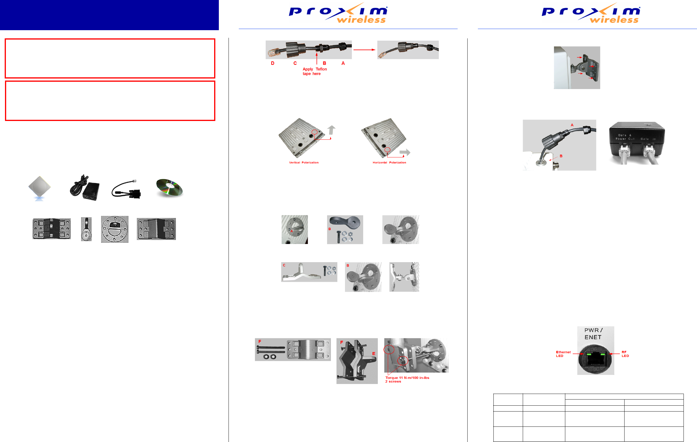
1. Slide the sealing nut (A) over the bare end of the CAT5 cable.
2. Slide the lock nut (B) over the bare end of the CAT5 cable.
3. lide the sealing cap (C) over the bare end of the CAT5 cable. Make sure the red rubber gasket
is inside the cap.
4. Apply two wraps of 0.5” wide Teflon tape around 4 the threads of the lock nut (B) that will go
inside the sealing cap.
5. Thread the lock nut (B) onto the sealing cap (C), and hand tighten.
6. Terminate the RJ45 connectors (D) to both ends of the CAT5 cable; test for proper wiring using
a straight-through cable.
3 Determine Proper Mounting Orientation
Locate the arrow on the back of the unit and determine your desired mounting orientation. For
vertical polarization using the integrated antenna, the arrow should be pointing up (perpendicular
to the ground). For horizontal polarization using the integrated antenna, the arrow should be
horizontal (parallel to the ground).
4 Assemble Mounting Hardware
1. Attach the mounting plate (A) using the provided screws and washers (Torque 9 N·m/75 in-
lbs), such that the unit’s antenna will be vertically or horizontally polarized when mounted.
2. Attach the extension arm (B) to mounting plate (A) with the screw, nut, and washers provided,
as shown below. The extension arm gives the unit more possible tilt, letting you adjust for
azimuth or elevation over a larger angle.
3. Attach the mounting bracket (C) to extension arm (B) with the screw, nut, and washers
provided.
4. Finally tighten the assembly (Torque 15 N·m/130 in-lbs).
5 Mount the Unit
1. To pole-mount, insert screws through bracket F and fasten around the pole to bracket E and
secure (Torque 11 N.m/100 in-lbs). Longer bolts (not supplied) are required for mounting the
units to a pole with a diameter larger than 3 inches.
2.
To wall-mount the unit, mount bracket E to a wall using 4 screws (not provided), as shown
:
6 Plug in the Cables
1. Plug one end of the CAT5 cable (A) into the RJ45 jack of the unit (B).
2. Connect the free end of the CAT5 cable to the “Data and Power Out” port 2. on the power
injector.
3. To connect the unit through a hub or a switch to a PC, connect a straight-3. through Ethernet
cable between the network interface card in the PC and the hub, and between the hub and the
RJ45 “Data In” port on the PoE adapter.
To connect the unit directly to a PC, connect a cross-over Ethernet cable between the network
interface card in the PC and the RJ45 “Data In” port on the power injector.
7 Power on the Unit
The power adaptor provides Power-over-Ethernet (PoE), supplying electricity and wired
connectivity to the unit over a single 24 AWG CAT5 (diameter .114 to .250 inches/2.9 to 6.4 mm).
The unit is not 802.3af-compatible. Note that the Active Ethernet module provides +48 VDC over a
standard CAT5 Ethernet cable.
Once you have connected the power injector to the Ethernet cabling and plugged the power
injector cord into an AC outlet, the unit is powered on. There is no ON/OFF switch on the unit. To
remove power, unplug the AC cord from the AC outlet or disconnect the RJ45 connector from the
“Data and Power Out” port on the power injector.
Depressing the power adaptor’s Reload button for five seconds during power-up remotely resets
BS/SS parameters affecting communication between the BS and SS to their factory default
settings: IP address, subnet mask, user name, password, Ethernet speed/duplex, and VLAN
mode.
8View LED
Two LED indicators are available on the Ethernet port of the unit. These LEDs display the activity
of the Ethernet and RF links.
3650
IMPORTANT
This device must be installed by a trained professional, value added
reseller or systems integrator who is familiar with RF planning issues
and the regulatory limits.
CAUTION!
Heed all the WARNINGS. Follow all the instructions. Do not defeat the
safety purpose of the grounding. Only use attachments/accessories
specified by the manufacturer.
BS/SS Power Adaptor Installer CD
Mounting Clamp
for Wall/Pole
Extension
Arm
Mounting
Plate
Mounting Clamp
for Pole
Serial Cable
LED State Ethernet LED RF (Wireless) LED
Base Station Subscriber Station
Off No Ethernet link Radio is off Radio is off
On Ethernet link is
connected
Radio is active
(transmitting downlink
and receiving uplink)
Downlink synchronized.
Flashing Packets are
being received
on Ethernet.
Unit is in standby Increasing on-off speed
indicates increasing
RSNR.
4 5 6
9 Align the Antenna
Antenna alignment is the process of physically aligning the antenna of the radio receiver and
transmitter to have the best possible link established between them. The antenna alignment
process is usually performed during installation and after major repairs.
If you are installing external antennas, consult the documentation that accompanies the antenna
for installation instructions. Note that you must weatherproof the antenna connectors as described
in Weatherproof the Connectors.
To ensure correct antenna alignment:
1. Perform a link budget calculation to obtain an expected signal level. A link budget calculator is
available at http://support.proxim.com
2. Compare the calculation to the SNR value on the SS by logging into the SS Web interface and
clicking
Monitor > Statistics > MAC Statistics
.
3. If needed, physically adjust the antenna, and refresh the.
Monitor > Statistics > MAC
Statistics
page to take a new SNR reading.
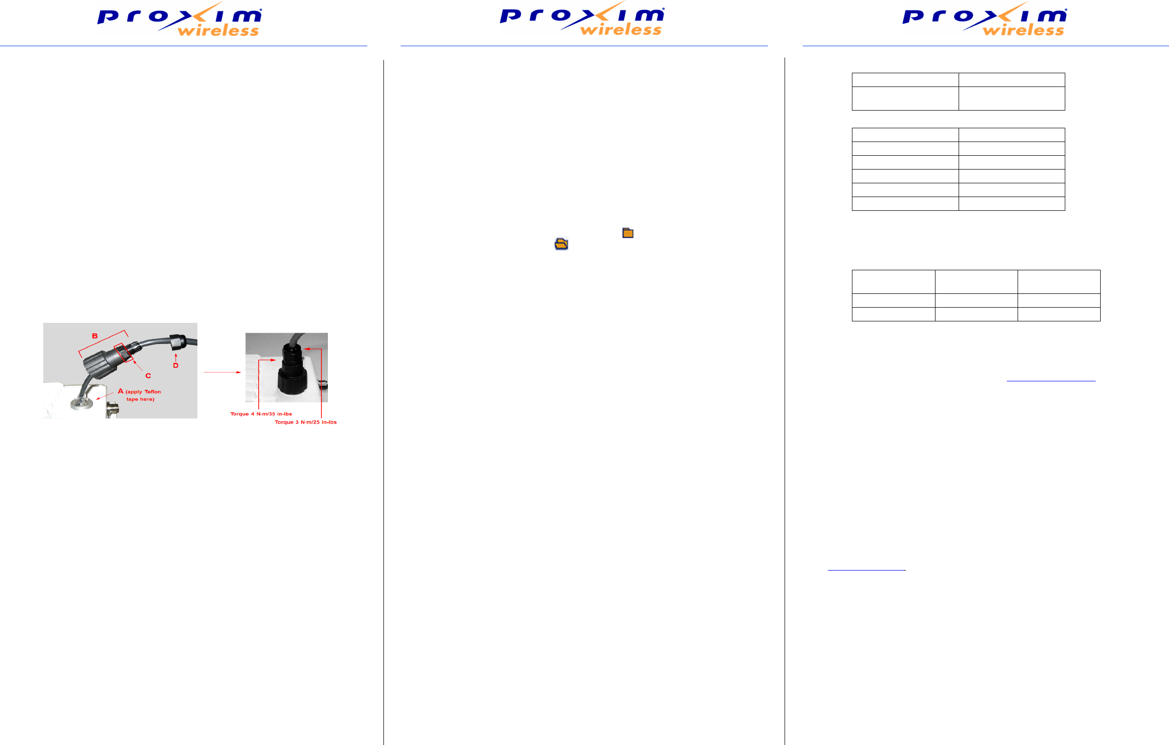
10 Tighten the Cable
1. Apply two wraps of Teflon tape around the threads of the unit’s RJ45 jack (A) in a clockwise
direction.
2. Make sure that the red rubber gasket is still seated in the sealing cap of the sealing cap/lock nut
assembly (B).
3. Slide the sealing cap/lock nut assembly (B) over the RJ45 jack (A) and thread onto enclosure.
Hand tighten first, then use a pipe wrench or similar tool to tighten one more quarter turn.
4. Tighten the lock nut (C) (Torque 4 N.m/35 in-lbs).
5. Thread the sealing nut (D) onto the sealing cap/lock nut assembly (B) and tighten (Torque 3
N.m/25 in-lbs).
11 Weatherproof the Connectors
1. Remove the film liner from the rubber-based tape strip.
2. Stretch and wrap the tape around the connector tightly, starting below the connector cap and
against the unit and wrapping in a clockwise direction. Wrap the tape once around the base of
the connector cap.
3. Seal the tape tightly against the connector and the cable.
4. Apply a layer of black electrical tape (not provided) over the rubber-based tape for further
protection. Make sure the electrical tape also extends beyond the rubber-based tape to seal it.
12 Install the Documentation and Software
To install the documentation and software on a computer or network, insert the CD into the CD-
ROM drive. The installer starts automatically. If it does not, double click on the setup.exe on the
installation CD.
The following documentation and software products are installed.
Click Start > All Programs > Tsunami > MP.16 3650
• Documentation (in –Docs subdirectory):
— Installation and Management Guide
— Quick Installation Guide
— Safety and Regulatory Guide
— Recommended Antenna Guide
— Antenna Installation Guide
— MP.16 3650 Online Help
All of these items are also available from C:\Program Files\Tsunami\MP.16 3650.
• Available from C:\Program Files\Tsunami\MP.16 3650:
— Documentation (in Docs folder): See list above
— Help files (in Help folder; click on index.htm to access)
— TFTP Server (in Extras folder)
Unit Initialization
1. Open a Web browser on a network computer.
2. Enter the unit’s IP address in the browser’s Address field and press
Enter
or
Go
.
The default IP address of the BS is https:\192.168.10.1.
The default IP address of the SS is https:\192.168.10.2.
3. To log in as an administrator, enter
admin
in the User Name field. Enter the password in the
Password field. For new units, the default administrator password is
public
.
4. To log in as a user, enter user in the
User
Name field. Enter the password in the Password field.
For new units, the default password is
public
.
Proxim strongly recommends that you change these passwords to more secure ones. Refer to the
the Tsunami MP.16 3650 System User Guide for instructions.
5. Click on any of the menu items on the left side of the screen to begin configuring the unit.
Web Interface Navigation
1. Menu: Use the collapsible menu on the left of your screen to navigate through the web
interface. For headings (marked with a folder icon: ) click on the arrow to the left of the
heading to expand its contents ( ). Configuration pages (marked with a page icon:) are
used for configuring the unit.
2.
Configuration parameters:
View and change the unit’s settings in the “work area.” Enter
required or desired values in available fields, or use drop down menus to make selections.
When you have configured a page, you must click the
OK
button to save your changes. If you
do not click the
OK
button, the configuration parameters you specified will not be set.
First Configuration
The MP.16 system operates with little required setup. However, the administrator must initially
configure certain parameters to allow the BS and SS to communicate and (if desired) to secure the
network.
The following parameters must be set in order for the units to communicate:
•Center frequency: On the BS and SS Web interfaces, click Configuration >Radio to set the
desired frequency.
The following parameters must be set to ensure that the network is secure:
• IP address:
— On the BS Web interface, click Configuration > Networking > Basic to set the IP
address.
— On the SS Web interface, click Configuration > Network to set the IP address.
•Passwords: On the BS Web interface, click Commands > Passwords to set HTTPS and
CLI passwords.
•Net Entry mode: On the BS Web interface, click Configuration > SS Authentication to set
the Net Entry mode and default SS Class.
More information on these parameters as well as more advanced configuration options can be
found in following chapters in the Tsunami MP.16 3650 System User Guide:
• “Base Station Configuration” contains information and advanced Web-based configuration
options for the BS, including the use of Service Classes.
• “Subscriber Station Configuration” contains information and advanced Web-based
configuration options for the SS.
• “Command Line Interface” contains information on configuring the BS/SS via the CLI.
Information for Professional Installers
Adjusting Tx Output Power
Use the following formula in combination with the table of EIRP limits to calculate system transmit
power (based on EIRP limits):
Tx Power Allowed (dBm) = EIRP Limit (dBm) + CL (dB) - G (dB)
Where:
Certification Summary
Technical Support
Proxim eService Web Site Support
The Proxim eService Web site is available 7x24 at: http://support.proxim.com
Telephone Support
Contact technical support via telephone as follows:
•US and Canada: 408-383-7700, 866-674-6626 (Toll Free)
Hours of Operation: 8.00AM-6.00PM, Pacific Time, Monday-Friday
•APAC Countries: +91 40 23115490
Hours of Operation: 9.00AM-6.00PM, IST (UTC/GMT +5.30 Hrs.), Monday-Friday
•International: 408-383-7700
Hours of Operation: 8.00AM-6.00PM, Pacific Time, Monday-Friday
ServPak Support
ServPak is a program of Enhanced Service Options that can be purchased individually or in
combinations to meet your needs.
• Advanced Replacement
• Extended Warranty
• 7x24 Technical Support
• Priority Queuing
To learn more, please call Proxim Support at 408-383-7700 or send an email to
servpak@proxim.com. To purchase ServPak support services, please contact your authorized
Proxim distributor.
Tx Power = Output power measured at the antenna input
EIRP Limit = EIRP limits specified below
CL = Coax cable loss including loss of connectors
G = Antenna Gain
Frequency (GHz) EIRP Limit (dBm)
3.650 - 3.675 38 @ 7 MHz channels
35 @ 3.5 MHz channels
Antenna Type Maximum Gain (dBi)
Dipole 8
60 degree sector 17
90 degree sector 14
120 degree sector 17
Flat Panel 18
Country Type Certification/
Reference Number
USA Base Station HZB-MP163650
USA Subscriber Station HZB-MP163650S
1561 Buckeye Drive
Milpitas, California 95035
Phone: (408) 383-7600
Fax: (408) 383-7680
www.proxim.com