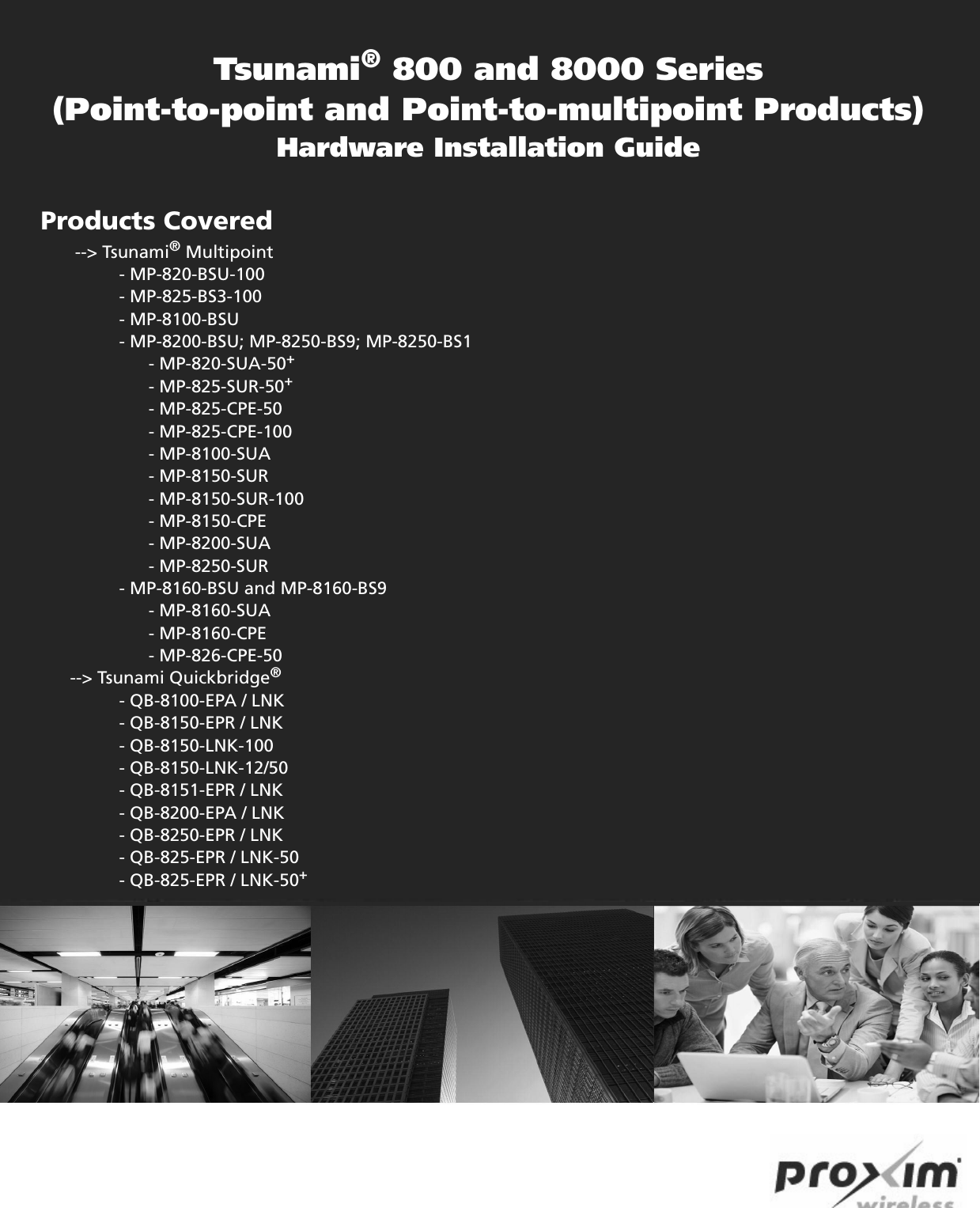
Proxim Wireless PROXMB82 802.11A/B/G/N MPCI MODULE User Manual Hardware Installation Guide
Proxim Wireless Corporation 802.11A/B/G/N MPCI MODULE Hardware Installation Guide
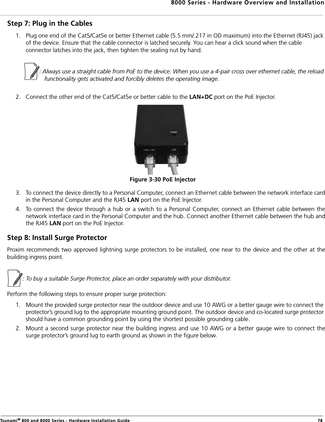
Contents
- 1. User Manual
- 2. users manual-1
- 3. users manual-2
- 4. Software guide1
- 5. software guide2
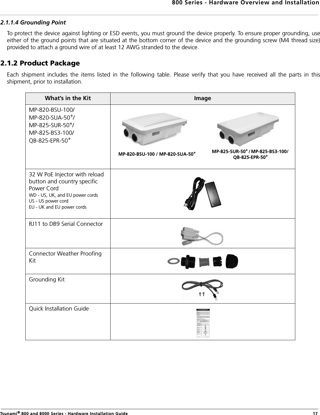
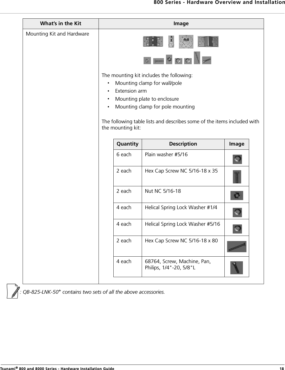
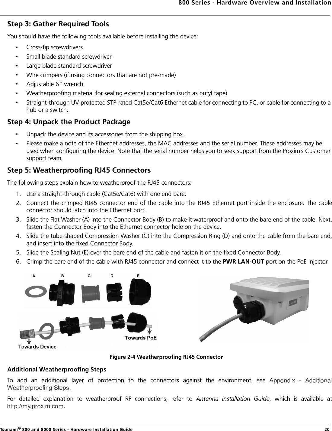
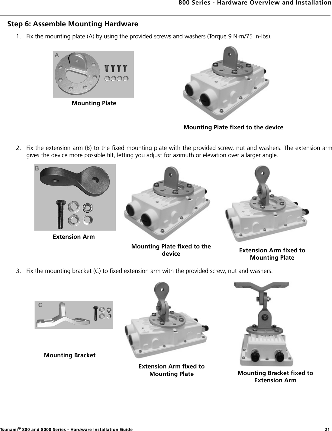
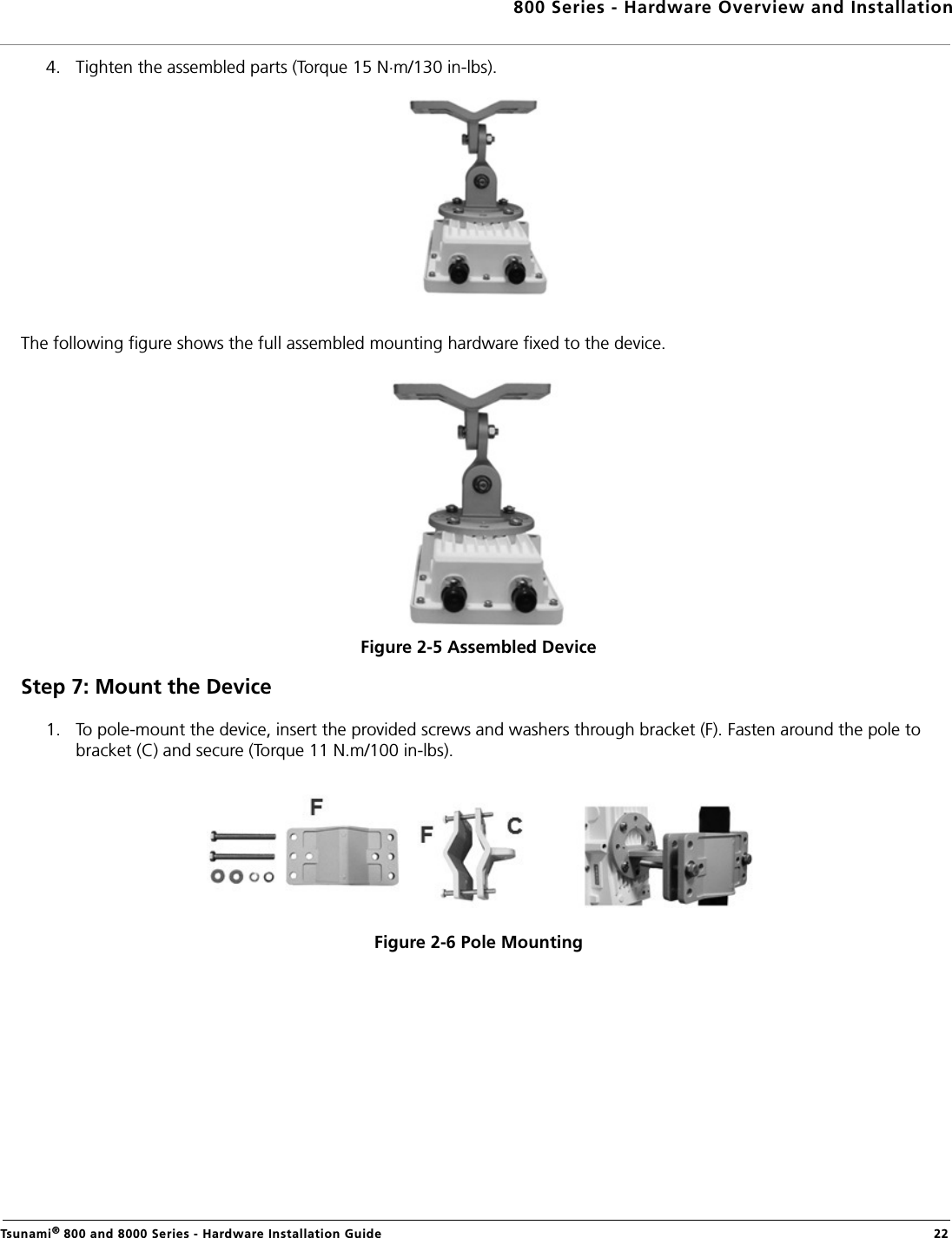
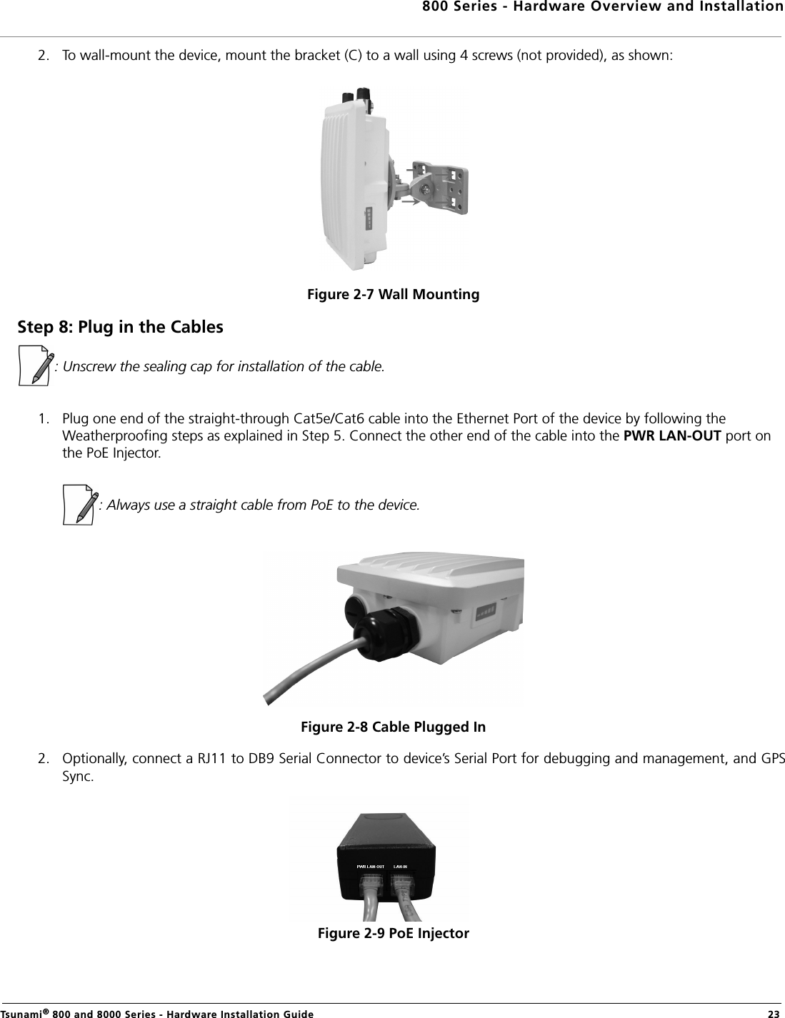
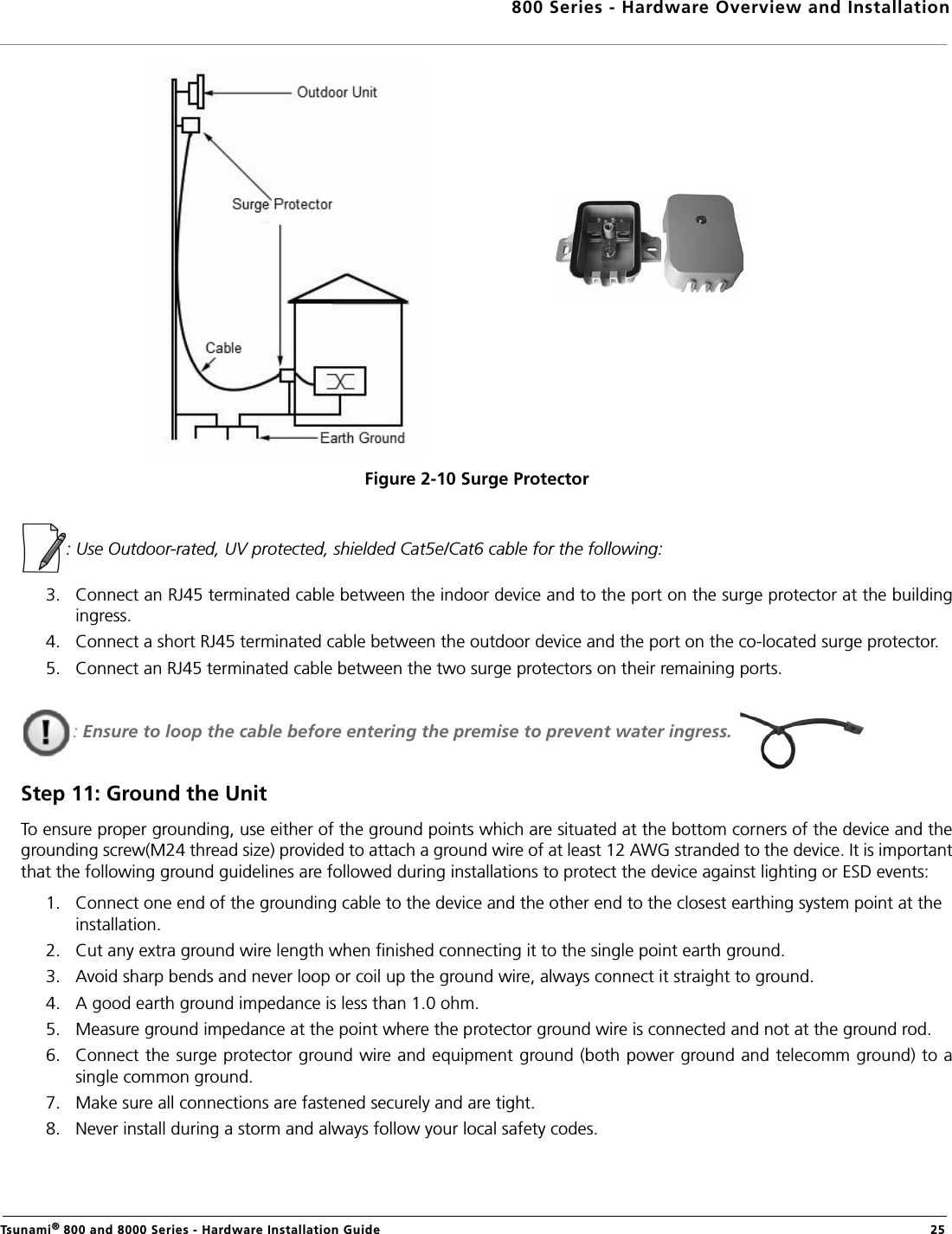
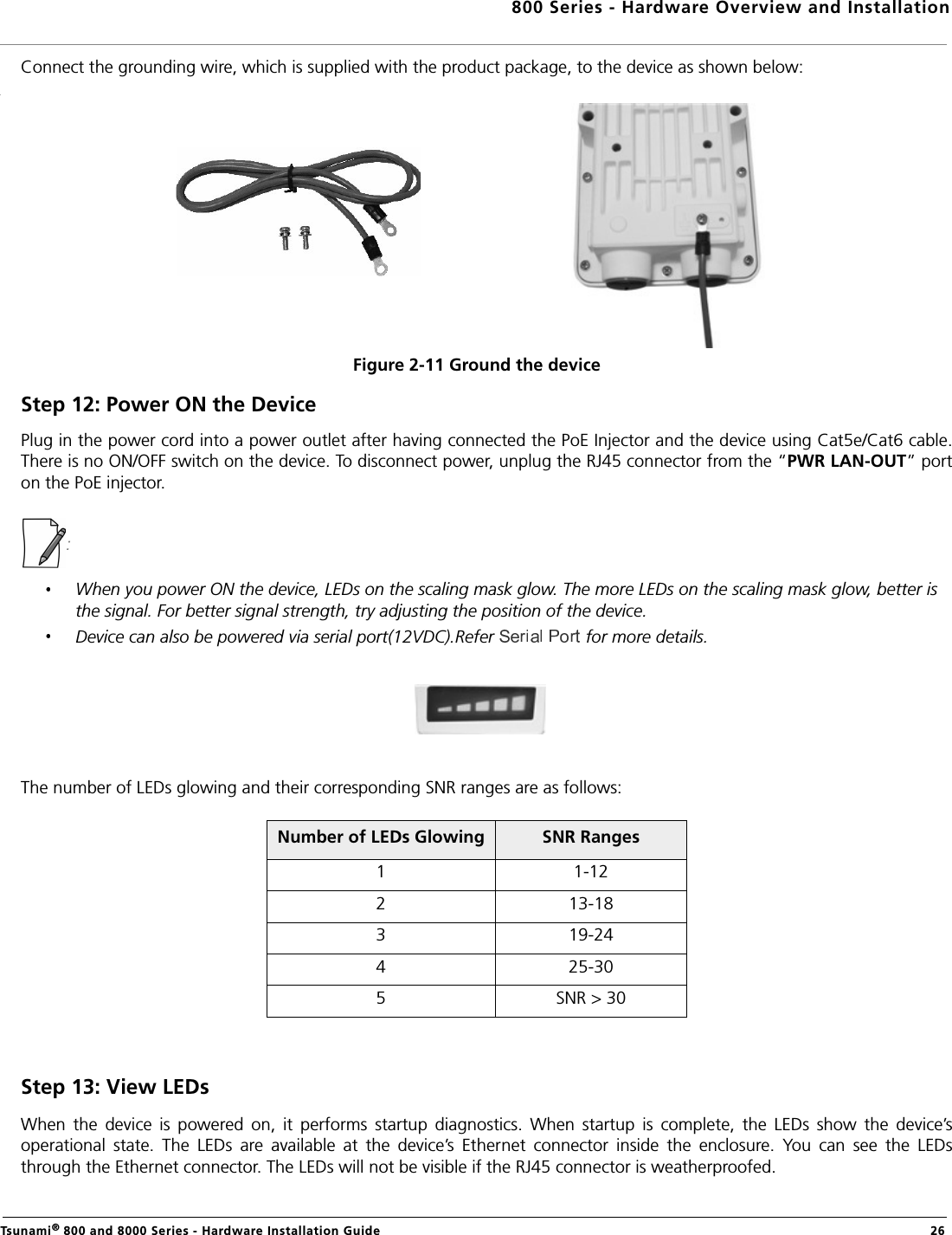
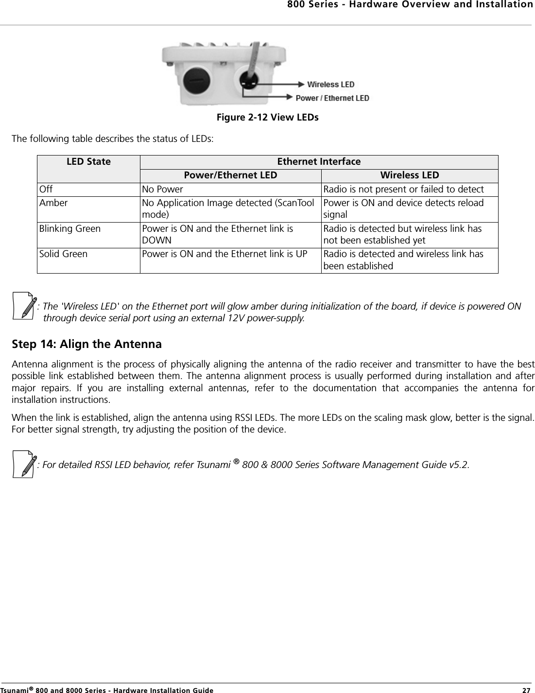
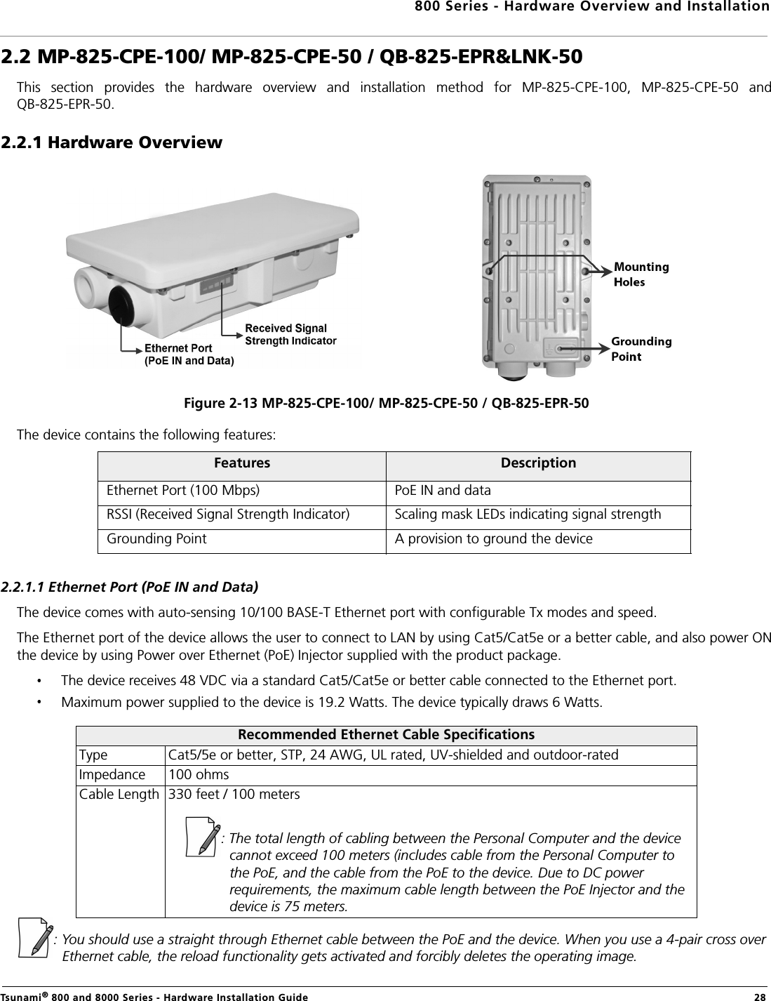
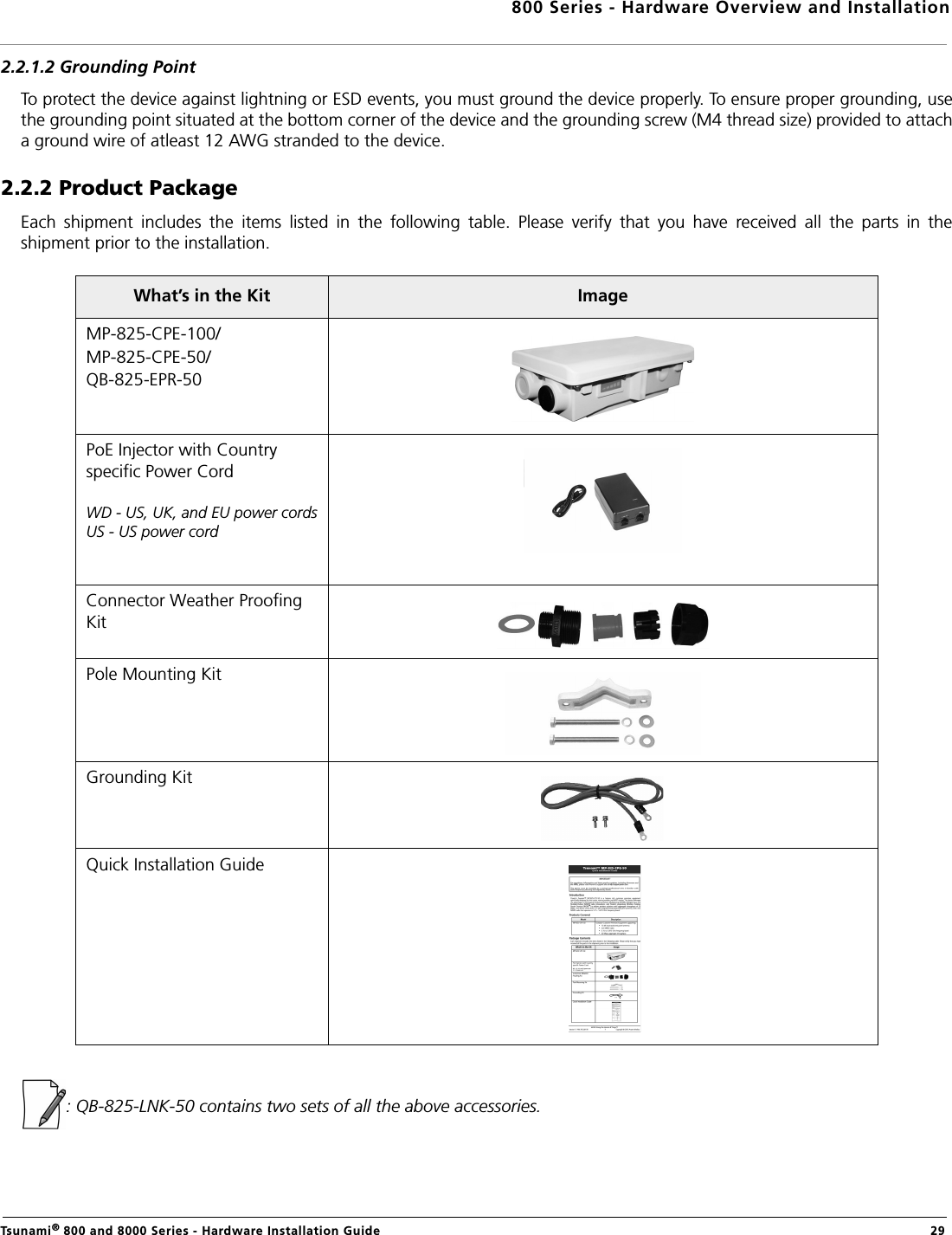
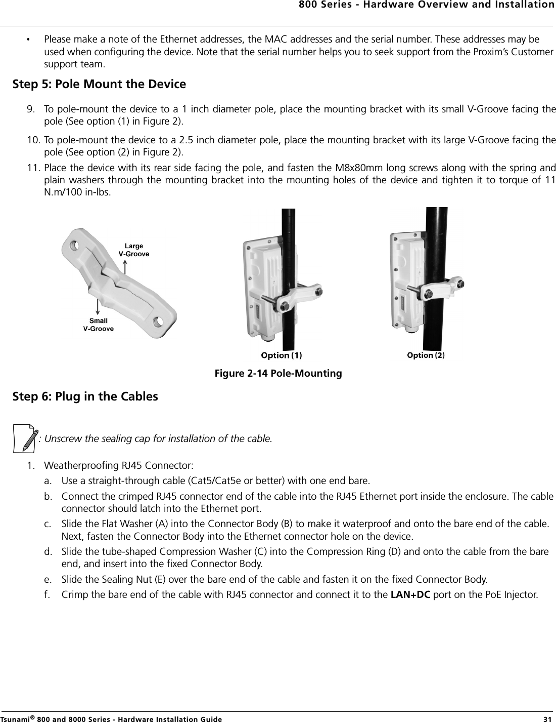
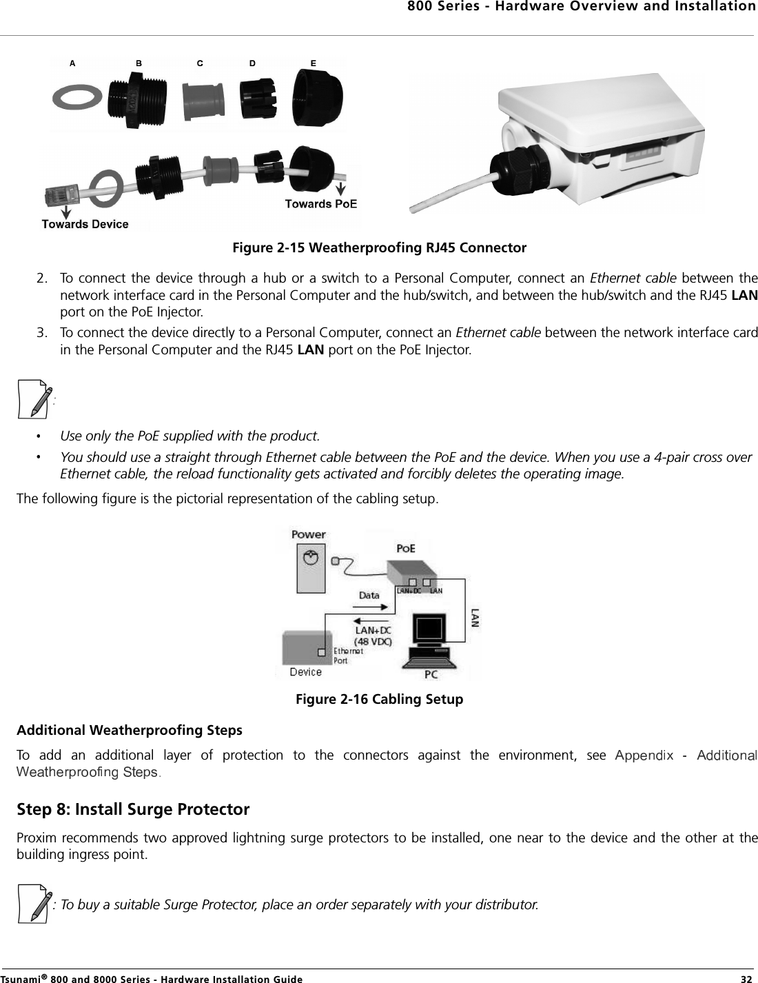
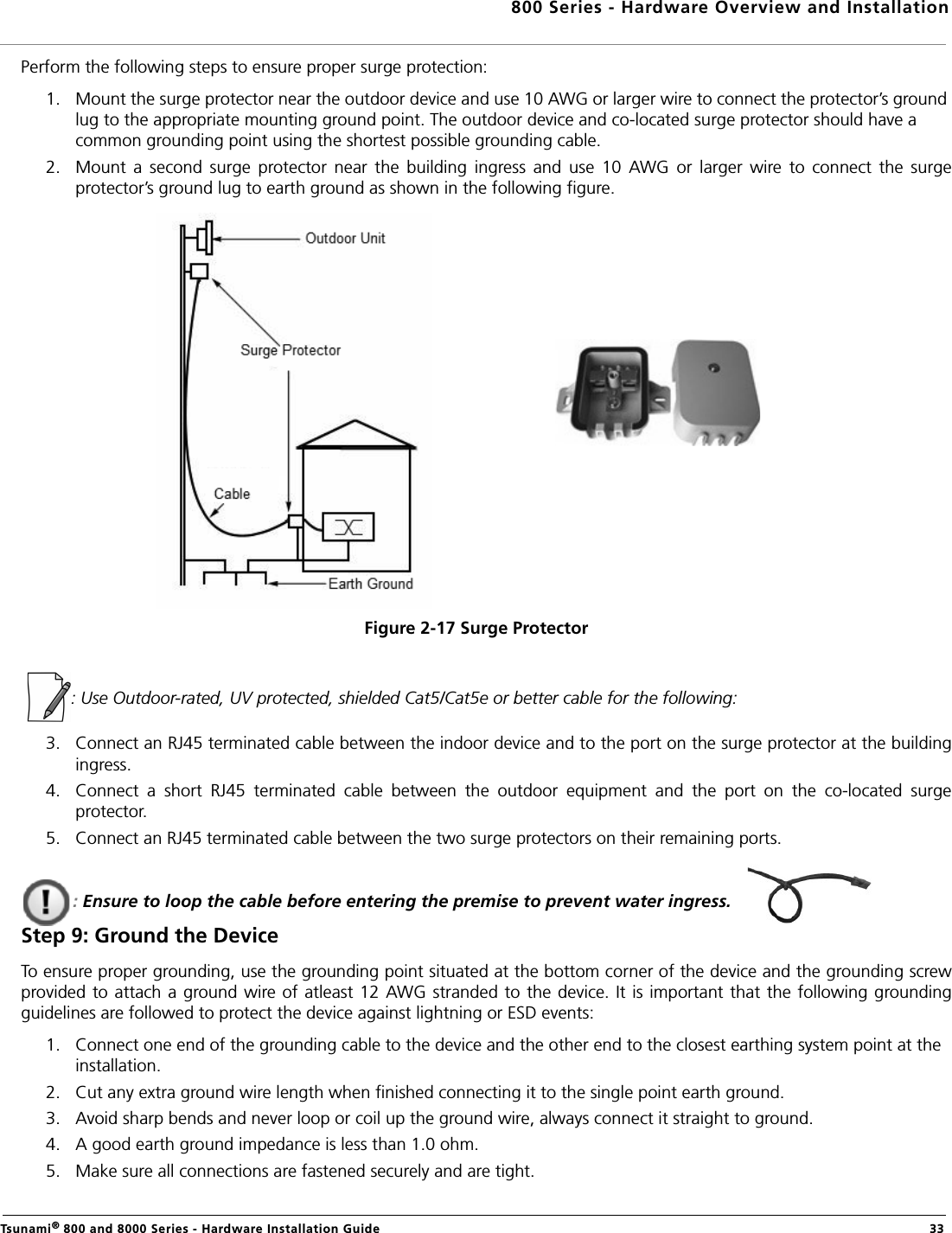
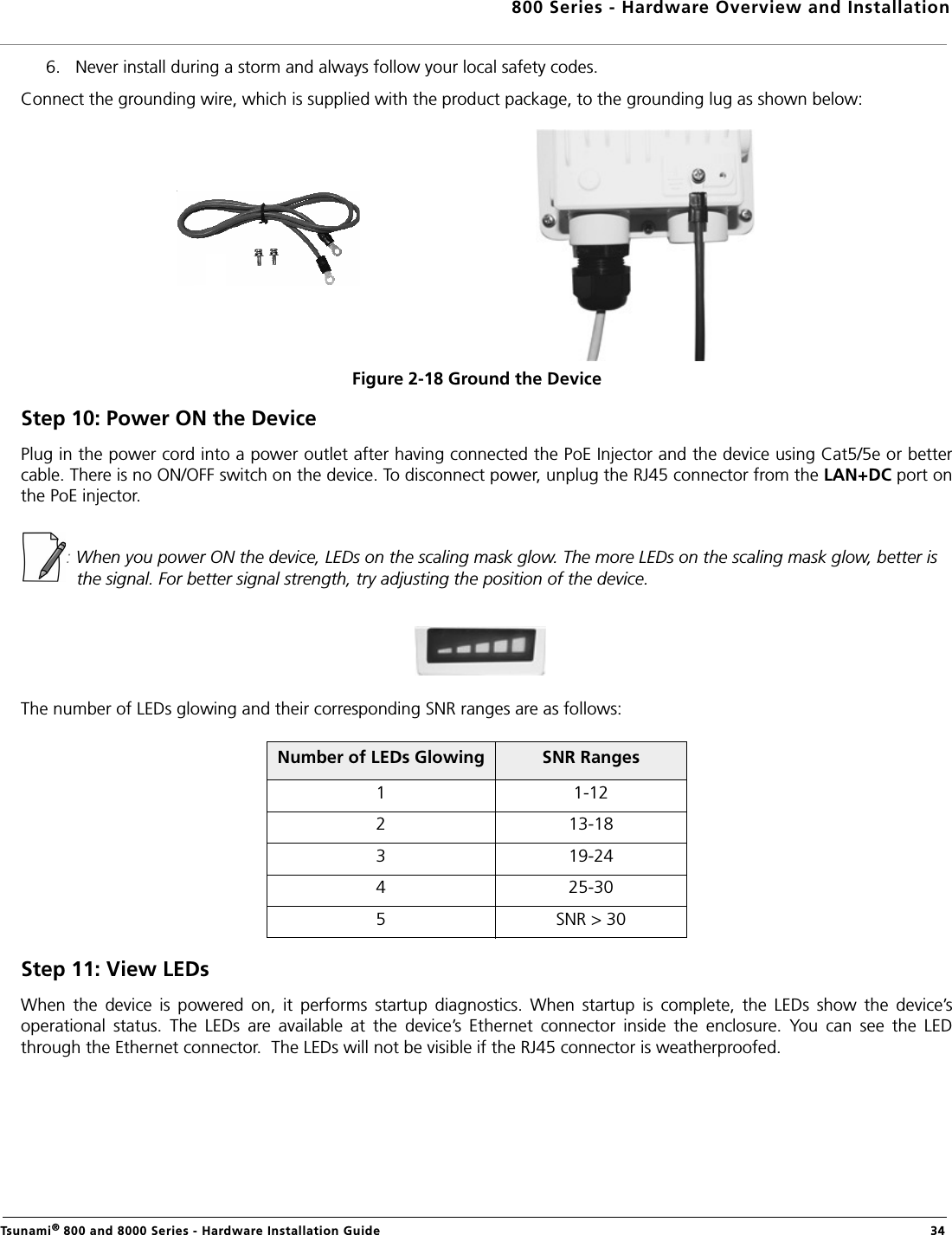
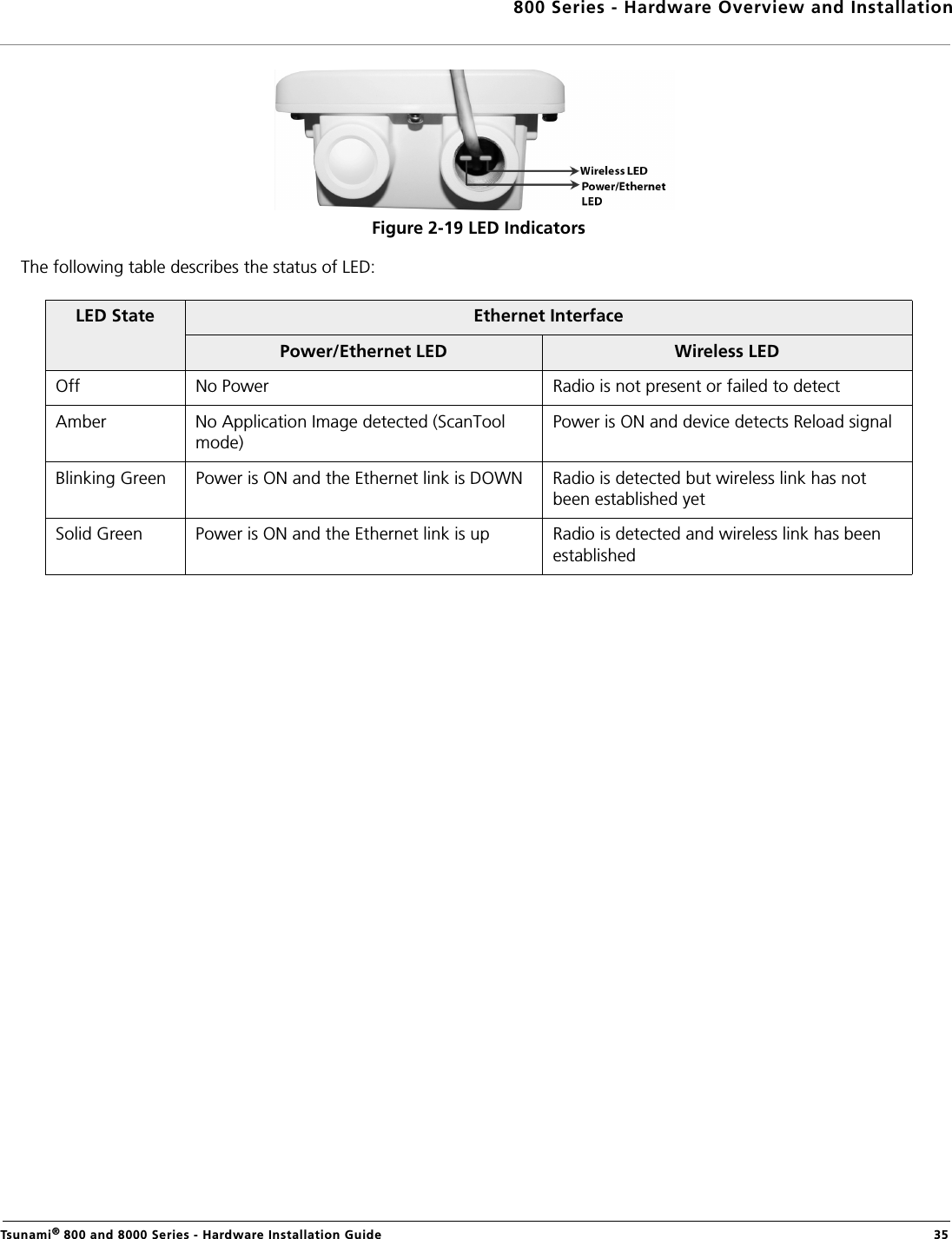
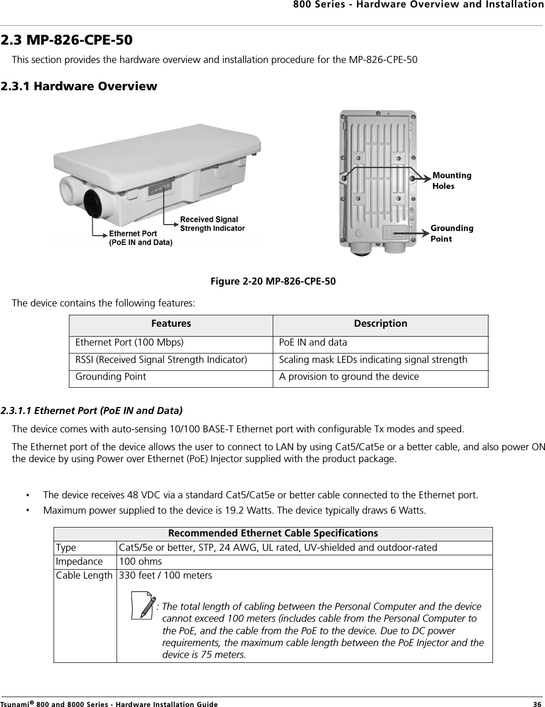
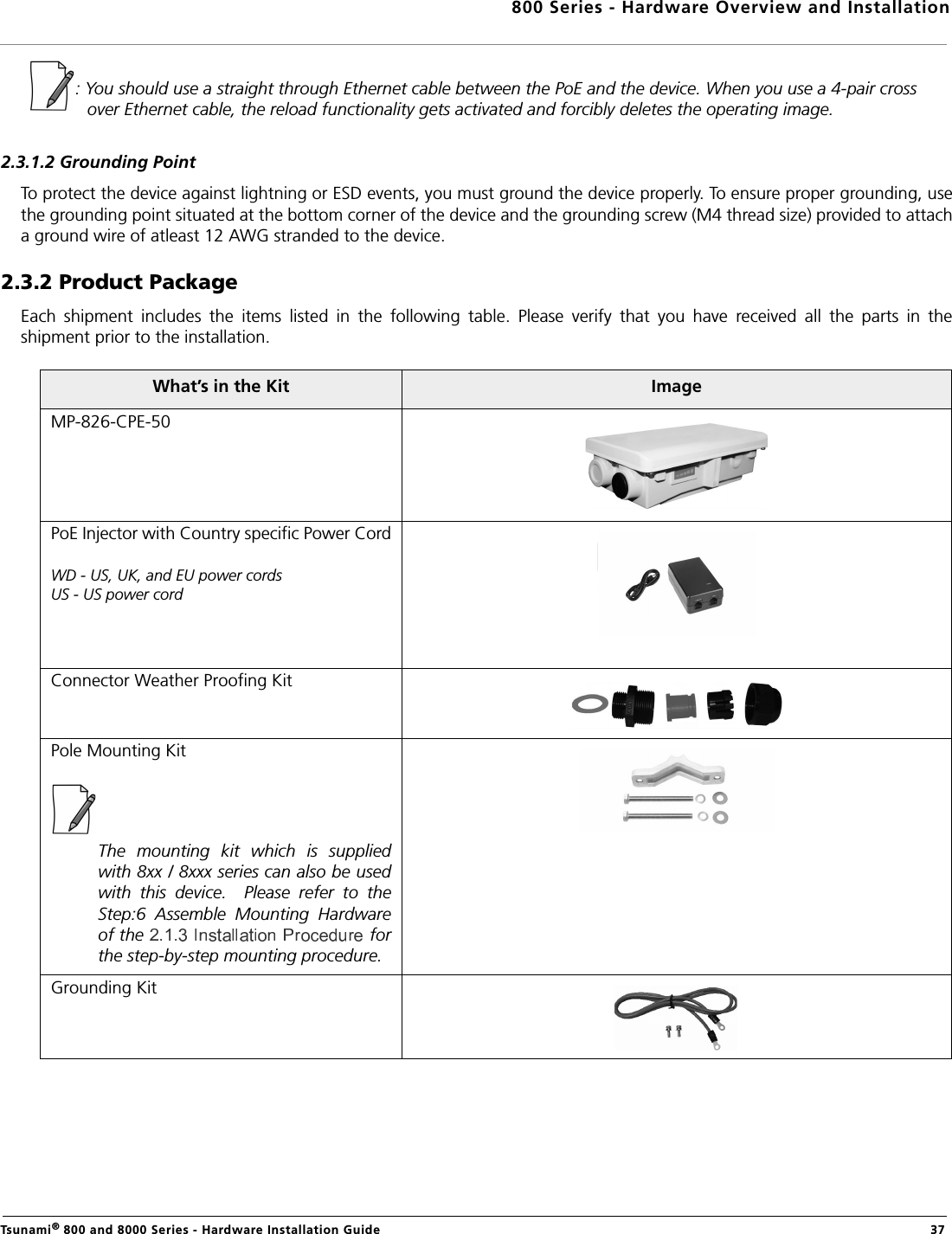
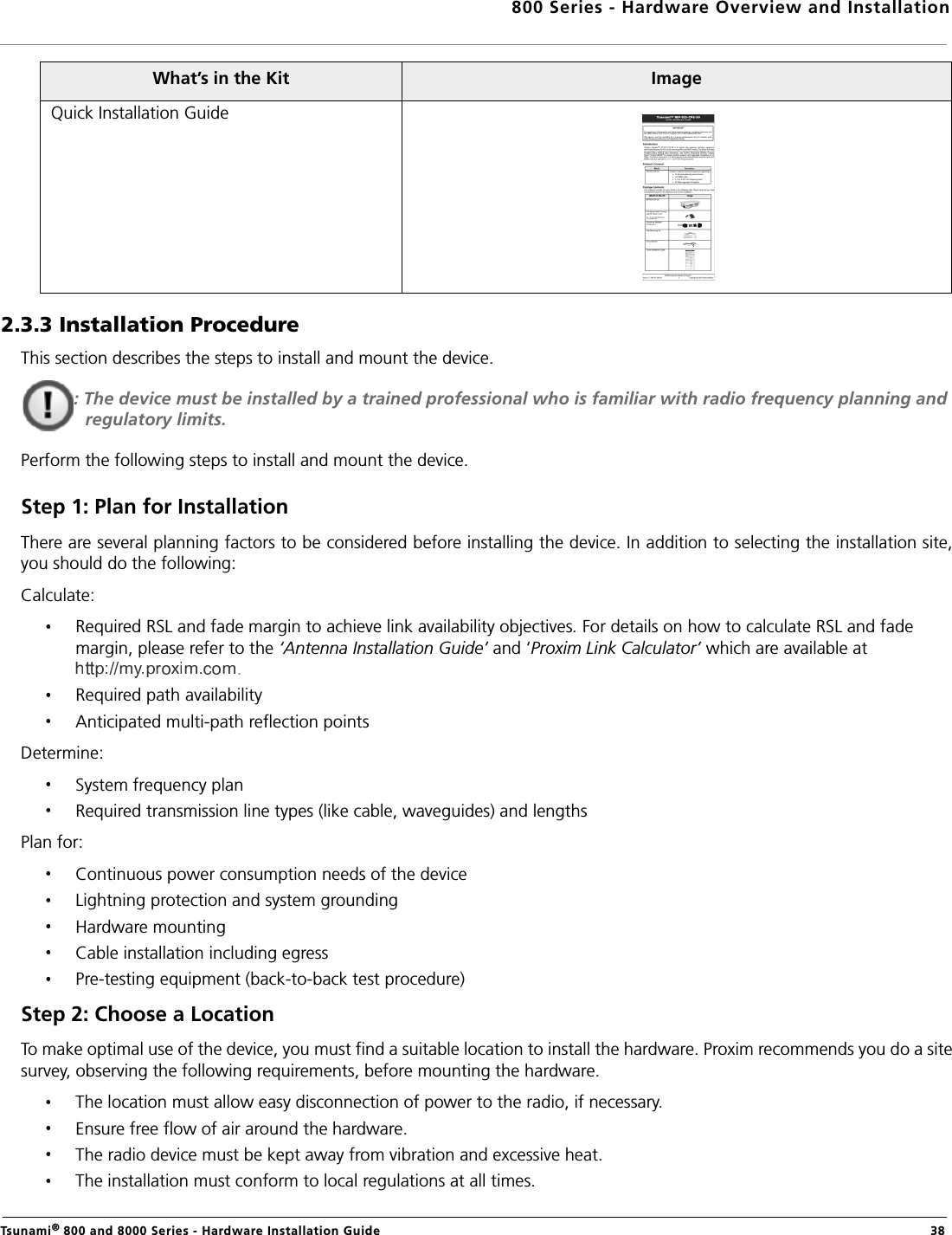
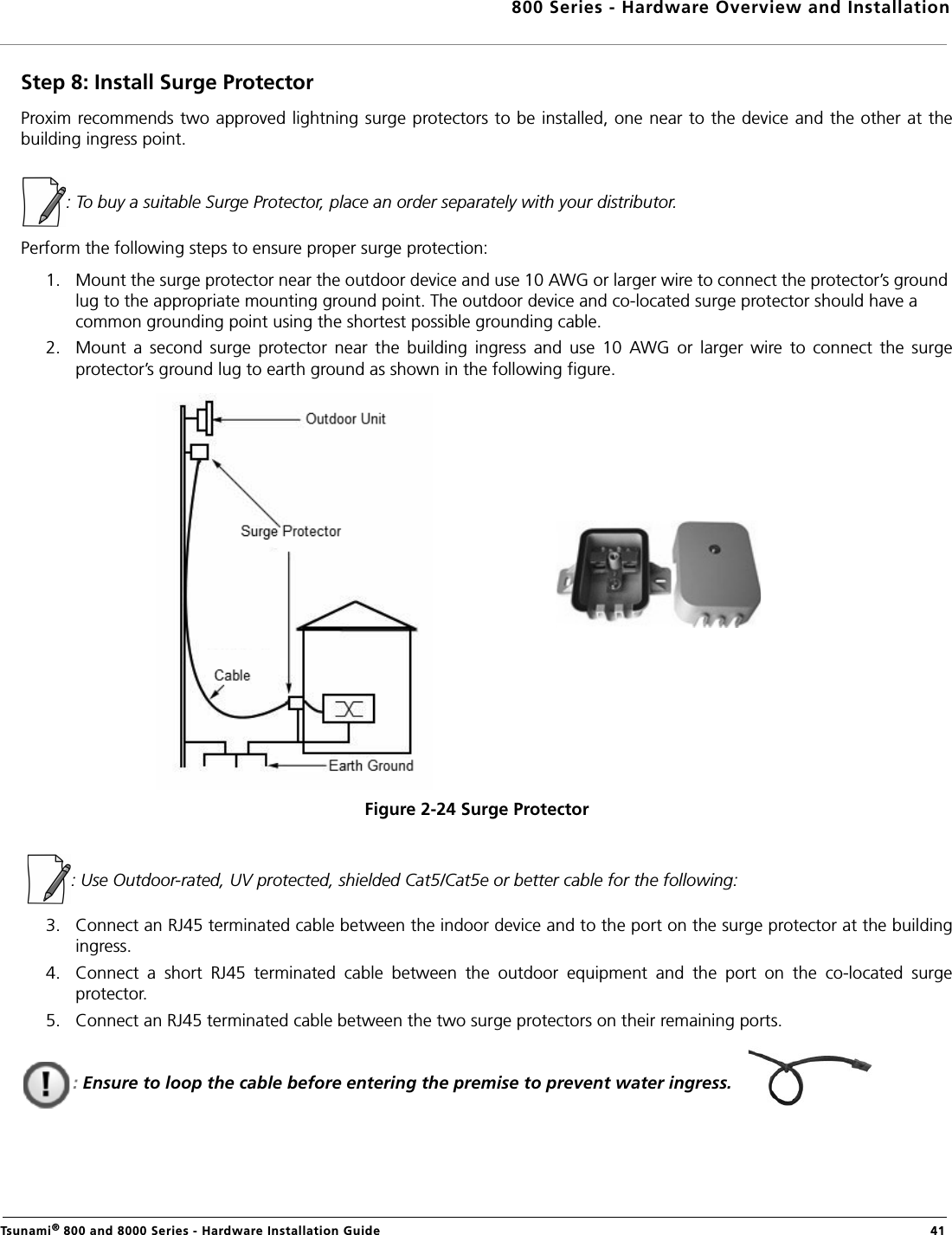
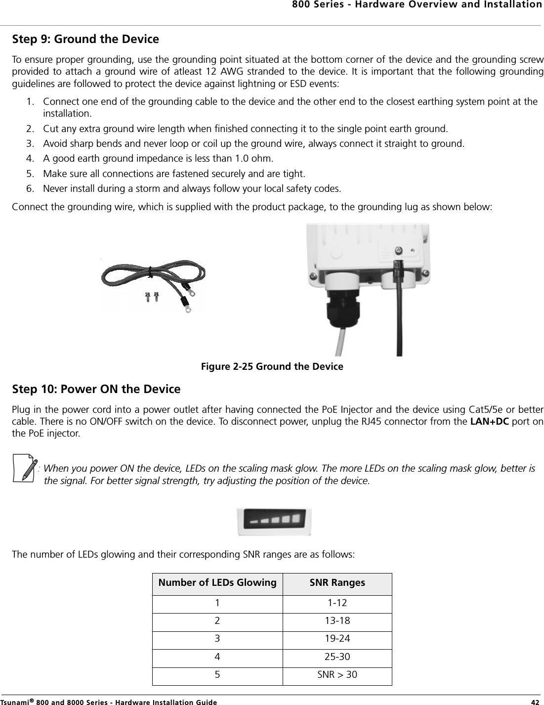
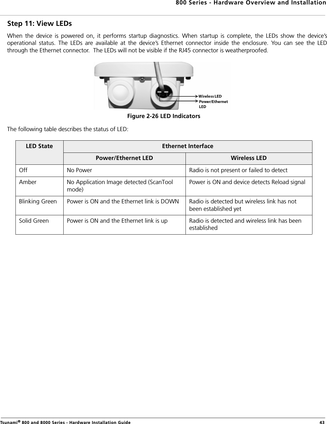
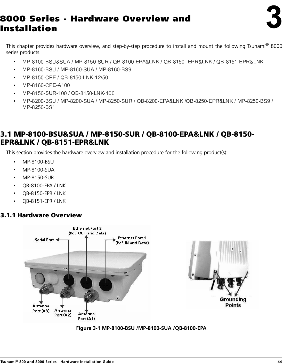
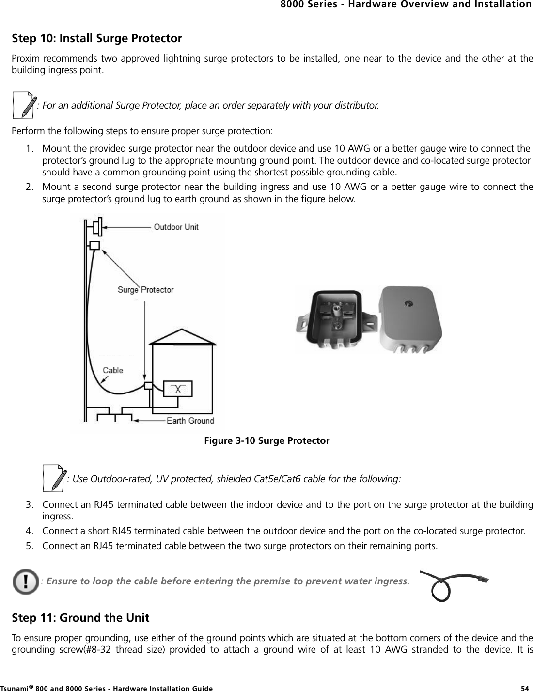
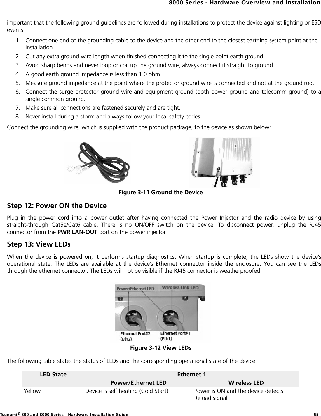
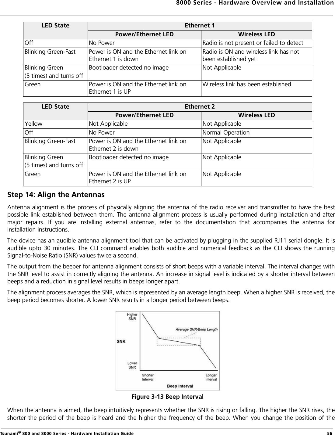
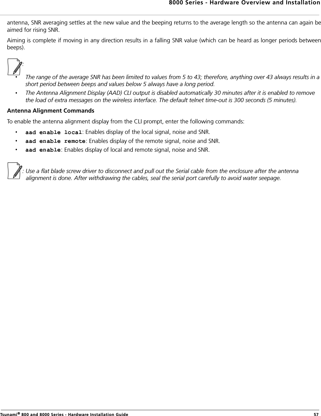
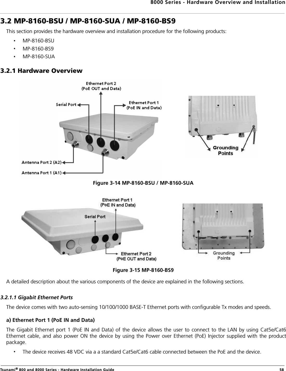
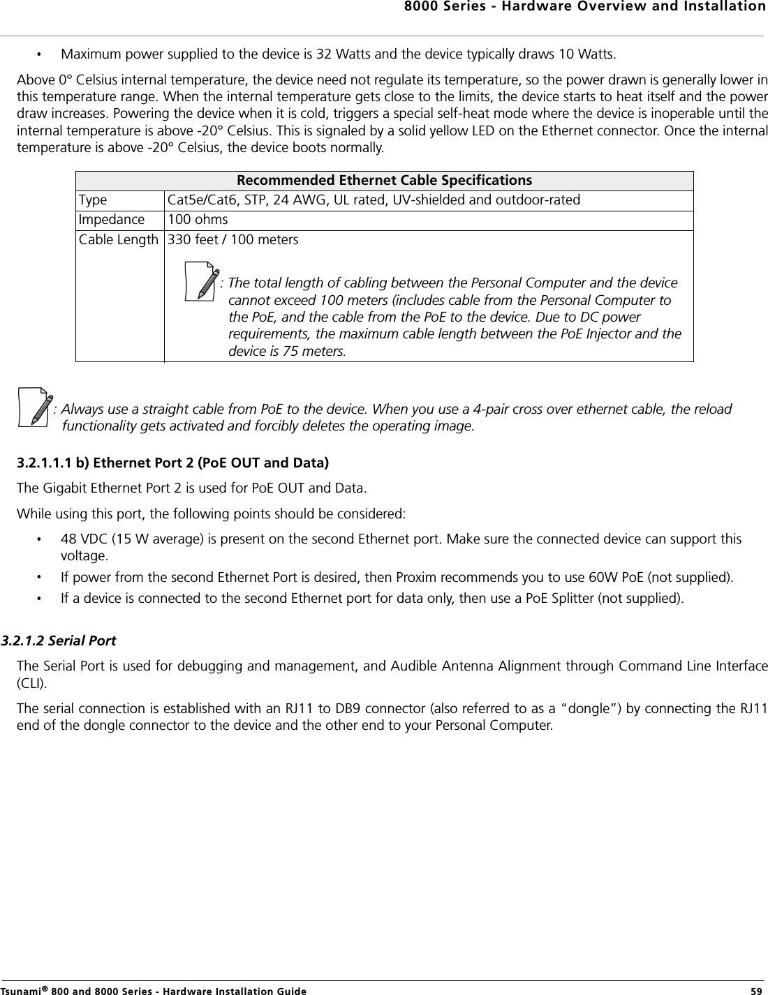
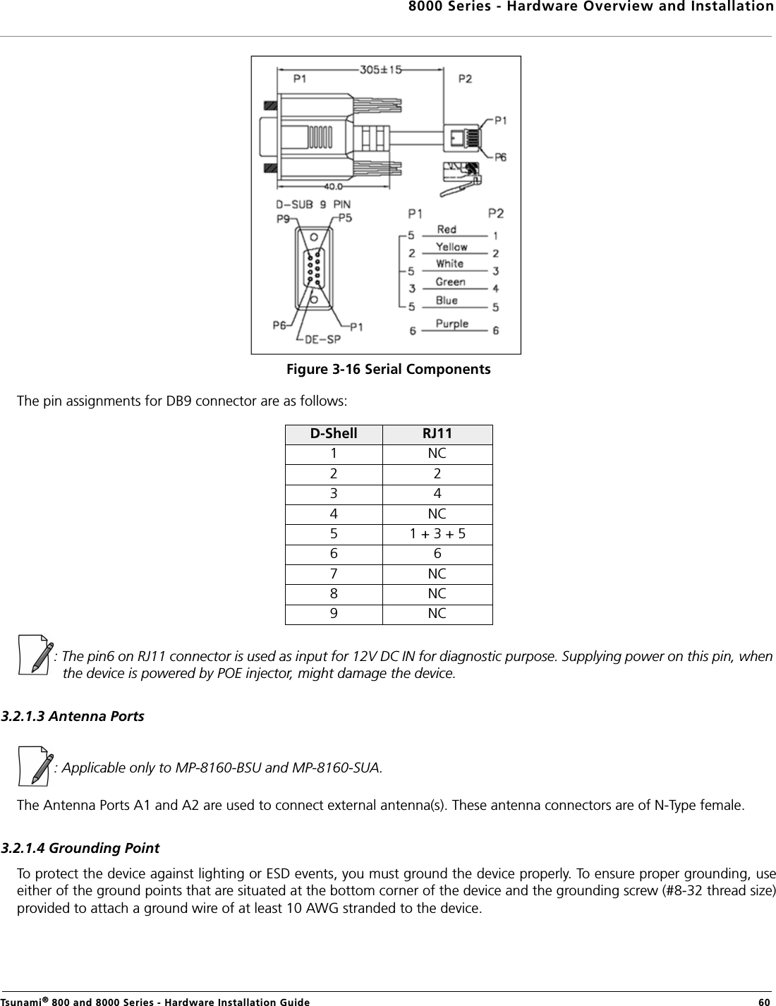
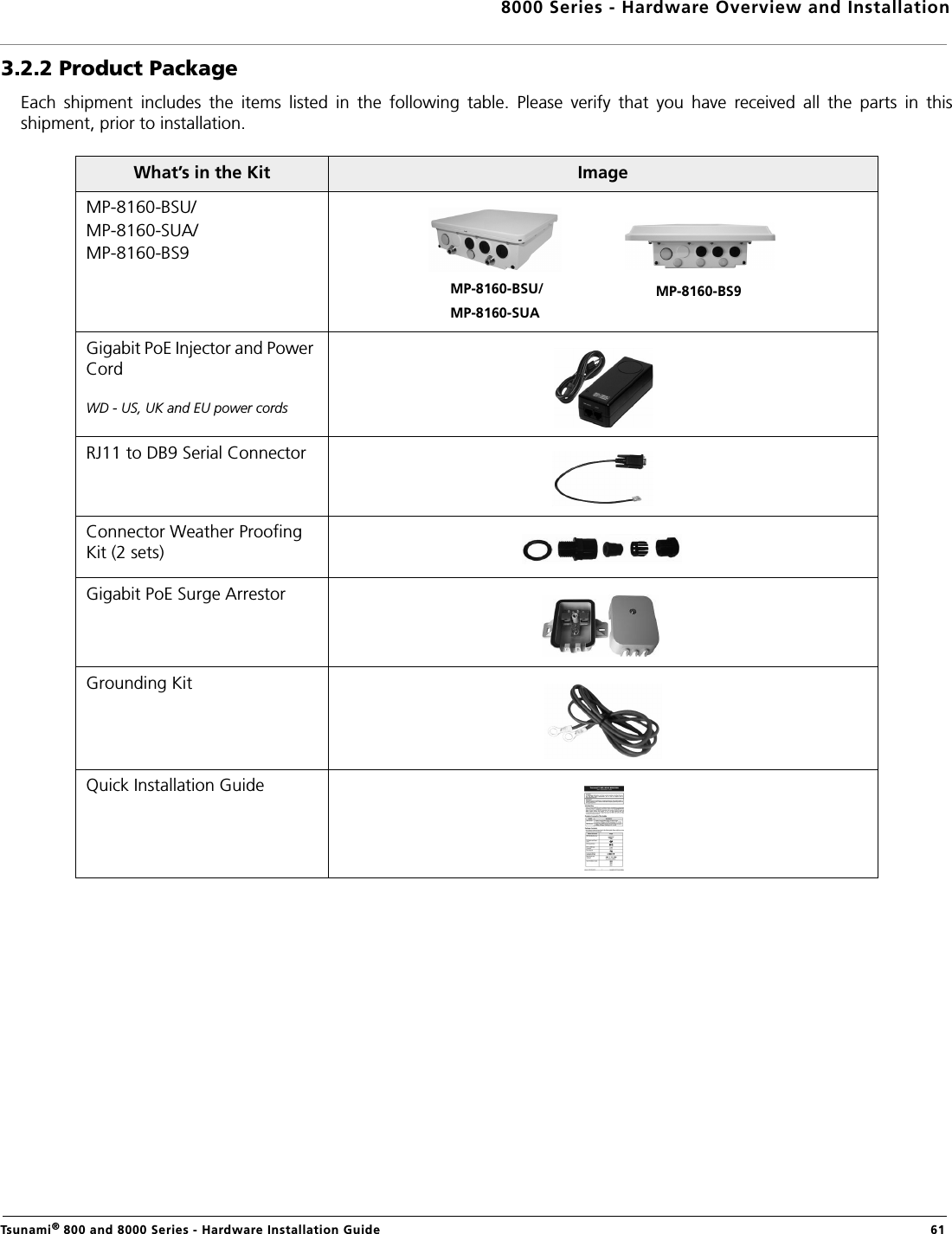
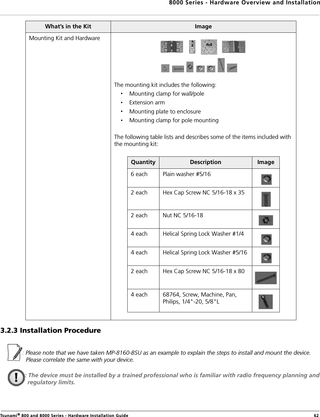
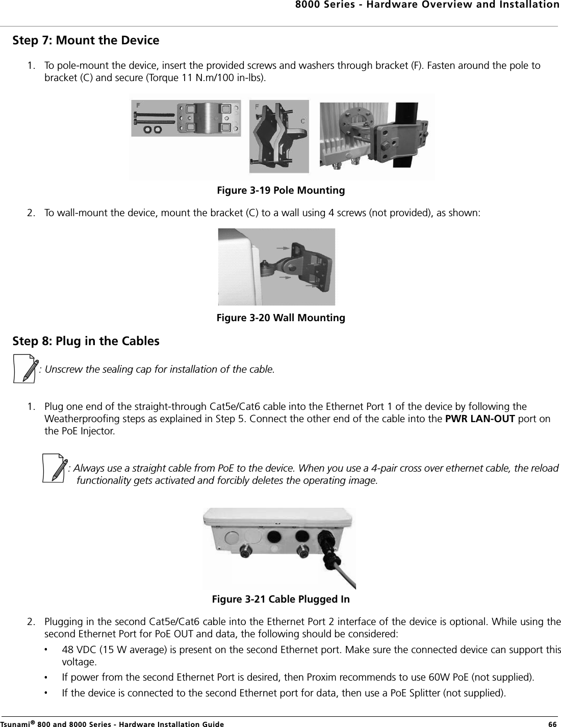
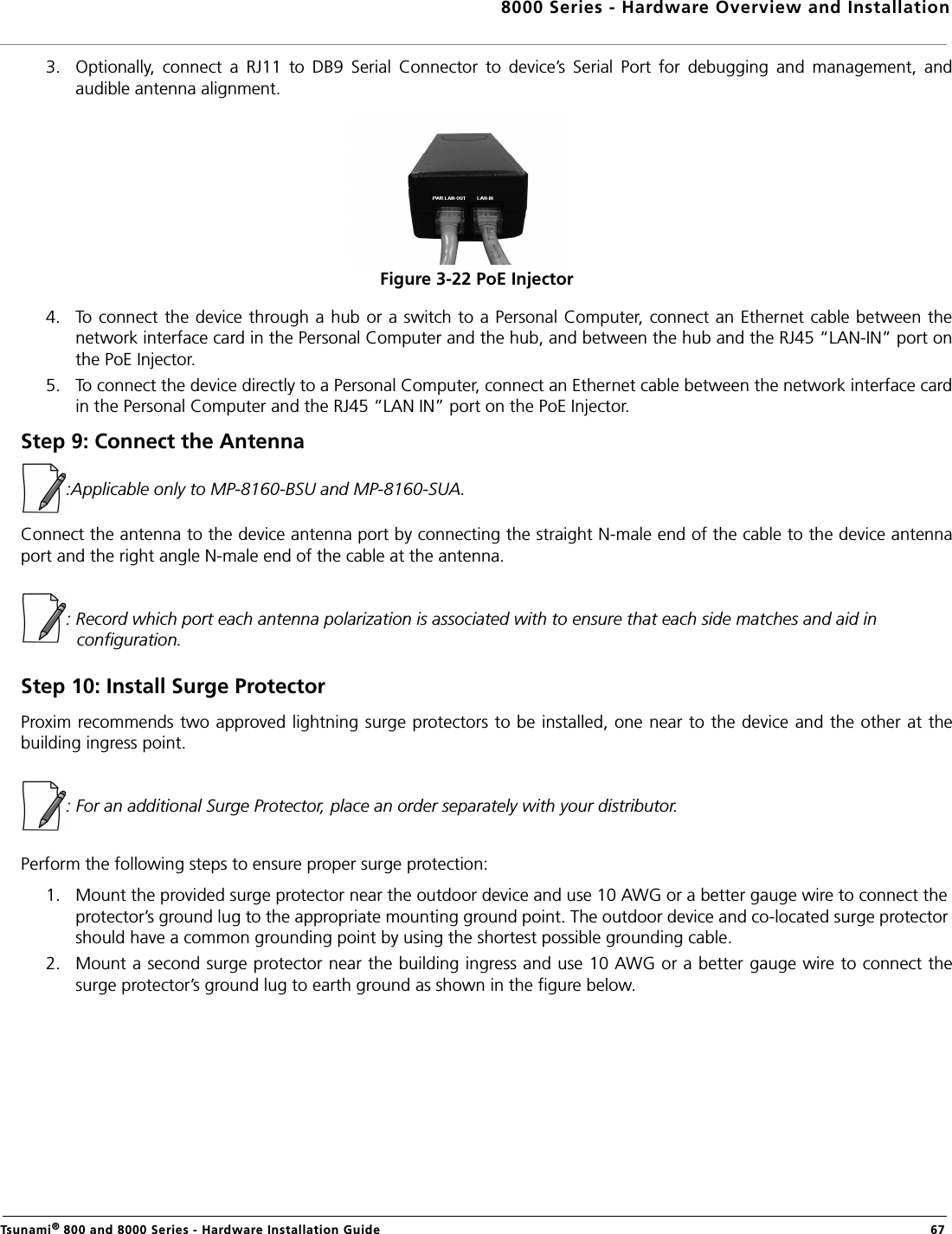
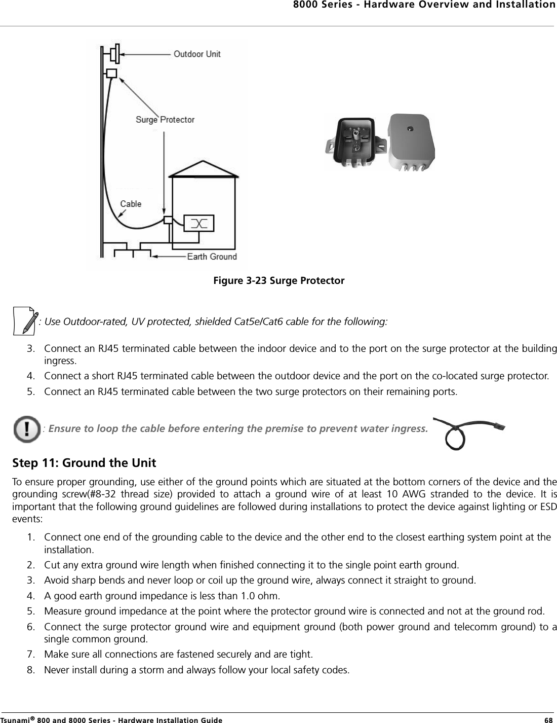
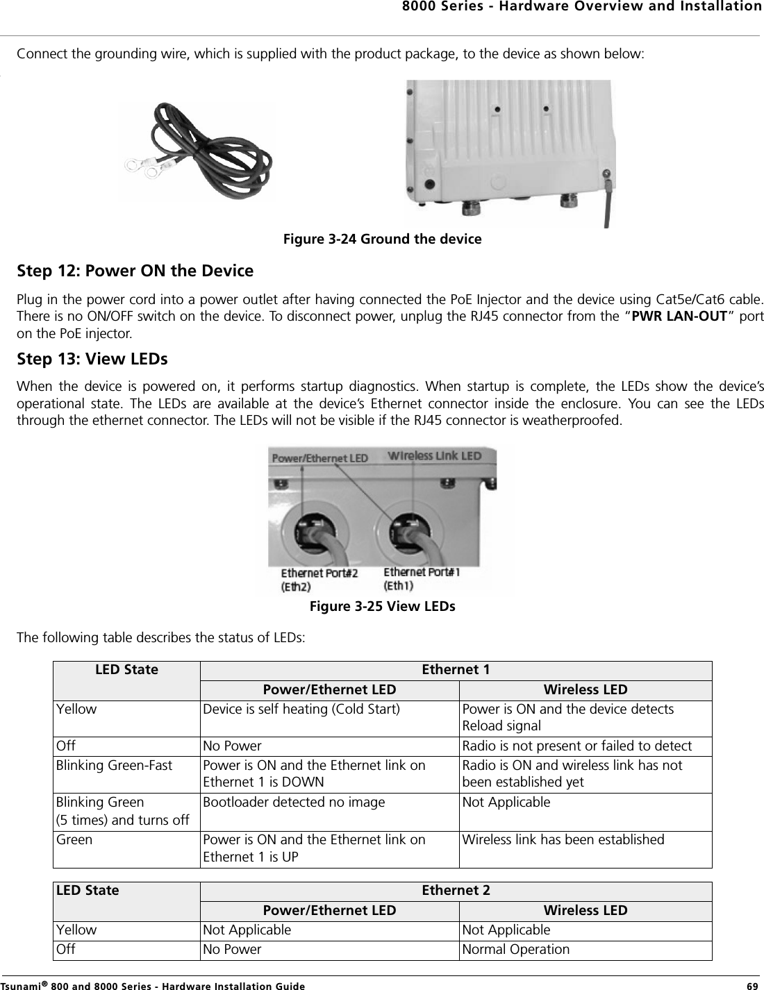
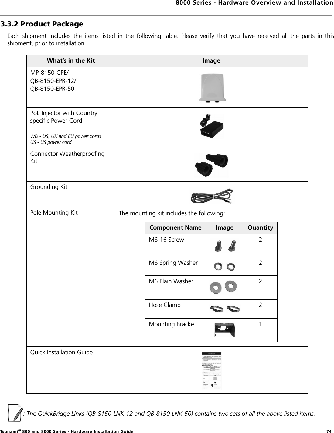
users manual-1