Proxim Wireless PROXMB92 miniPCI High Power MIMO IEEE 802.11 a/b/g/n RFModule User Manual QB 8100 100 5 Mbps Models User Guide
Proxim Wireless Corporation miniPCI High Power MIMO IEEE 802.11 a/b/g/n RFModule QB 8100 100 5 Mbps Models User Guide
Contents
- 1. Users Manual
- 2. user manual
- 3. Module user manual
- 4. System user manual
System user manual

Tsunami QB-8100 Series (100 Mbps / 5 Mbps Models)
Installation and Management Guide

Tsunami QB-8100 Series(100 Mbps/5 Mbps Models) Installation and Management Guide
2
Copyright
© 2010 Proxim Wireless Corporation, Milpitas, CA. All rights reserved. Covered by one or more of the following U.S. patents: 5,231,634;
5,875,179; 6,006,090; 5,809,060; 6,075,812; 5,077,753. This manual and the software described herein are copyrighted with all rights reserved.
No part of this publication may be reproduced, transmitted, transcribed, stored in a retrieval system, or translated into any language in any form by
any means without the written permission of Proxim Wireless Corporation.
Trademarks
Tsunami, Proxim, and the Proxim logo are trademarks of Proxim Wireless Corporation. All other trademarks mentioned herein are the property of
their respective owners.
Disclaimer
Proxim reserves the right to revise this publication and to make changes in content from time to time without obligation on the part of Proxim to
provide notification of such revision or change. Proxim may make improvements or changes in the product(s) described in this manual at any time.
When using this device, basic safety precautions should always be followed to reduce the risk of fire, electric shock and injury to persons.
GPL License Note
Tsunami QB-8100 includes software code developed by third parties, including software code subject to the GNU General Public License ("GPL") or
GNU Lesser General Public License ("LGPL"). Please see the GPL and LGPL Web sites to view the terms of each license.
To access the GPL Code and LGPL Code used in Tsunami QB-8100, visit the proxim website to get a copy of the source. The GPL Code and LGPL
Code used in this device are distributed WITHOUT ANY WARRANTY and are subject to the copyrights of one or more authors. For details, see the
GPL Code and LGPL Code of this device and the terms of the GPL and LGPL.
Tsunami QuickBridge 8100 Series (100 Mbps/5 Mbps Models) Installation and Management Guide
Version 1.0
P/N 765-00038, May 2010
IMPORTANT!
Proxim recommends you to visit the Proxim Support site at http://support.proxim.com for Regulatory
Information and latest product updates.

Tsunami QB-8100 Series(100 Mbps/5 Mbps Models) Installation and Management Guide
3
Preface. . . . . . . . . . . . . . . . . . . . . . . . . . . . . . . . . . . . . . . . . . . . . . . . . . . . . . . . . . . . . . . . . . . . . . 8
1 Overview . . . . . . . . . . . . . . . . . . . . . . . . . . . . . . . . . . . . . . . . . . . . . . . . . . . . . . . . . . . . . . . . . . . 10
Introduction . . . . . . . . . . . . . . . . . . . . . . . . . . . . . . . . . . . . . . . . . . . . . . . . . . . . . . . . . . . . . . . . . . . . . . . . 11
Wireless Network Topology (Point-to-Point Link) . . . . . . . . . . . . . . . . . . . . . . . . . . . . . . . . . . . . . . . . . . . . 12
Multiple-Input-Multiple-Output (MIMO) . . . . . . . . . . . . . . . . . . . . . . . . . . . . . . . . . . . . . . . . . . . . . . . . . . . . 12
Management and Monitoring Capabilities . . . . . . . . . . . . . . . . . . . . . . . . . . . . . . . . . . . . . . . . . . . . . . . . . 14
Web Interface. . . . . . . . . . . . . . . . . . . . . . . . . . . . . . . . . . . . . . . . . . . . . . . . . . . . . . . . . . . . . . . . . . . . . . . . . . . . . 14
Command Line Interface . . . . . . . . . . . . . . . . . . . . . . . . . . . . . . . . . . . . . . . . . . . . . . . . . . . . . . . . . . . . . . . . . . . . 14
SNMP Management. . . . . . . . . . . . . . . . . . . . . . . . . . . . . . . . . . . . . . . . . . . . . . . . . . . . . . . . . . . . . . . . . . . . . . . . 14
2 Installation and Initialization . . . . . . . . . . . . . . . . . . . . . . . . . . . . . . . . . . . . . . . . . . . . . . . . . . . 16
Hardware Overview . . . . . . . . . . . . . . . . . . . . . . . . . . . . . . . . . . . . . . . . . . . . . . . . . . . . . . . . . . . . . . . . . . 17
Power-over-Ethernet . . . . . . . . . . . . . . . . . . . . . . . . . . . . . . . . . . . . . . . . . . . . . . . . . . . . . . . . . . . . . . . . . . . . . . . 17
Serial Connection. . . . . . . . . . . . . . . . . . . . . . . . . . . . . . . . . . . . . . . . . . . . . . . . . . . . . . . . . . . . . . . . . . . . . . . . . . 18
Product Package . . . . . . . . . . . . . . . . . . . . . . . . . . . . . . . . . . . . . . . . . . . . . . . . . . . . . . . . . . . . . . . . . . . . 18
Installation Procedure . . . . . . . . . . . . . . . . . . . . . . . . . . . . . . . . . . . . . . . . . . . . . . . . . . . . . . . . . . . . . . . . 20
Initialization . . . . . . . . . . . . . . . . . . . . . . . . . . . . . . . . . . . . . . . . . . . . . . . . . . . . . . . . . . . . . . . . . . . . . . . . 26
ScanTool . . . . . . . . . . . . . . . . . . . . . . . . . . . . . . . . . . . . . . . . . . . . . . . . . . . . . . . . . . . . . . . . . . . . . . . . . . . . . . . . 26
Setting the IP Address with ScanTool . . . . . . . . . . . . . . . . . . . . . . . . . . . . . . . . . . . . . . . . . . . . . . . . . . . . . . . . . . 26
Modifying the IP Address . . . . . . . . . . . . . . . . . . . . . . . . . . . . . . . . . . . . . . . . . . . . . . . . . . . . . . . . . . . . . . . . . . . . 27
Logging in to the Web Interface . . . . . . . . . . . . . . . . . . . . . . . . . . . . . . . . . . . . . . . . . . . . . . . . . . . . . . . . . 28
System Summary. . . . . . . . . . . . . . . . . . . . . . . . . . . . . . . . . . . . . . . . . . . . . . . . . . . . . . . . . . . . . . . . . . . . . . . . . . 29
COMMIT Button . . . . . . . . . . . . . . . . . . . . . . . . . . . . . . . . . . . . . . . . . . . . . . . . . . . . . . . . . . . . . . . . . . . . . . . . . . . 29
REBOOT Button. . . . . . . . . . . . . . . . . . . . . . . . . . . . . . . . . . . . . . . . . . . . . . . . . . . . . . . . . . . . . . . . . . . . . . . . . . . 30
Factory Default Configuration . . . . . . . . . . . . . . . . . . . . . . . . . . . . . . . . . . . . . . . . . . . . . . . . . . . . . . . . . . 32
3 Basic Configuration . . . . . . . . . . . . . . . . . . . . . . . . . . . . . . . . . . . . . . . . . . . . . . . . . . . . . . . . . . 33
Country and Related Settings . . . . . . . . . . . . . . . . . . . . . . . . . . . . . . . . . . . . . . . . . . . . . . . . . . . . . . . . . . 34
Dynamic Frequency Selection (DFS) . . . . . . . . . . . . . . . . . . . . . . . . . . . . . . . . . . . . . . . . . . . . . . . . . . . . . 34
Transmit Power Control . . . . . . . . . . . . . . . . . . . . . . . . . . . . . . . . . . . . . . . . . . . . . . . . . . . . . . . . . . . . . . . 35
Pairing the End Points or setting up a QB Link . . . . . . . . . . . . . . . . . . . . . . . . . . . . . . . . . . . . . . . . . . . . . 35
Virtual Local Area Networks (VLANs) . . . . . . . . . . . . . . . . . . . . . . . . . . . . . . . . . . . . . . . . . . . . . . . . . . . . 36
Quality of Service (QoS) . . . . . . . . . . . . . . . . . . . . . . . . . . . . . . . . . . . . . . . . . . . . . . . . . . . . . . . . . . . . . . 36
Basic Configuration Information . . . . . . . . . . . . . . . . . . . . . . . . . . . . . . . . . . . . . . . . . . . . . . . . . . . . . . . . . 37
4 Advanced Configuration . . . . . . . . . . . . . . . . . . . . . . . . . . . . . . . . . . . . . . . . . . . . . . . . . . . . . . 40
System Configuration . . . . . . . . . . . . . . . . . . . . . . . . . . . . . . . . . . . . . . . . . . . . . . . . . . . . . . . . . . . . . . . . . 41
Network Configuration . . . . . . . . . . . . . . . . . . . . . . . . . . . . . . . . . . . . . . . . . . . . . . . . . . . . . . . . . . . . . . . . 42
Configuring IP in Bridge or Router Mode . . . . . . . . . . . . . . . . . . . . . . . . . . . . . . . . . . . . . . . . . . . . . . . . . . . . . . . . 42
Ethernet Properties Configuration . . . . . . . . . . . . . . . . . . . . . . . . . . . . . . . . . . . . . . . . . . . . . . . . . . . . . . . 45

Tsunami QB-8100 Series(100 Mbps/5 Mbps Models) Installation and Management Guide
4
Wireless Configuration . . . . . . . . . . . . . . . . . . . . . . . . . . . . . . . . . . . . . . . . . . . . . . . . . . . . . . . . . . . . . . . . 46
Configuring WORP Properties in End Point A Mode . . . . . . . . . . . . . . . . . . . . . . . . . . . . . . . . . . . . . . . . . . . . . . . 46
Configuring WORP Properties in End Point B Mode . . . . . . . . . . . . . . . . . . . . . . . . . . . . . . . . . . . . . . . . . . . . . . . 51
Wireless Interface Properties . . . . . . . . . . . . . . . . . . . . . . . . . . . . . . . . . . . . . . . . . . . . . . . . . . . . . . . . . . . . . . . . . 51
Blacklist Information . . . . . . . . . . . . . . . . . . . . . . . . . . . . . . . . . . . . . . . . . . . . . . . . . . . . . . . . . . . . . . . . . . . . . . . . 56
Sensitivity Threshold Values . . . . . . . . . . . . . . . . . . . . . . . . . . . . . . . . . . . . . . . . . . . . . . . . . . . . . . . . . . . . . . . . . 56
MIMO Properties . . . . . . . . . . . . . . . . . . . . . . . . . . . . . . . . . . . . . . . . . . . . . . . . . . . . . . . . . . . . . . . . . . . . . . . . . . 56
DFS . . . . . . . . . . . . . . . . . . . . . . . . . . . . . . . . . . . . . . . . . . . . . . . . . . . . . . . . . . . . . . . . . . . . . . . . . . . . . . . . . . . . 58
DDRS . . . . . . . . . . . . . . . . . . . . . . . . . . . . . . . . . . . . . . . . . . . . . . . . . . . . . . . . . . . . . . . . . . . . . . . . . . . . . . . . . . . 61
Security Configuration . . . . . . . . . . . . . . . . . . . . . . . . . . . . . . . . . . . . . . . . . . . . . . . . . . . . . . . . . . . . . . . . 65
Setting Up Wireless Security . . . . . . . . . . . . . . . . . . . . . . . . . . . . . . . . . . . . . . . . . . . . . . . . . . . . . . . . . . . . . . . . . 65
Configuring the Radius Server Profile (End Point A Only) . . . . . . . . . . . . . . . . . . . . . . . . . . . . . . . . . . . . . . . . . . . 68
Configuring the MAC ACL (End Point A Only) . . . . . . . . . . . . . . . . . . . . . . . . . . . . . . . . . . . . . . . . . . . . . . . . . . . . 69
Quality of Service (QoS) Configuration . . . . . . . . . . . . . . . . . . . . . . . . . . . . . . . . . . . . . . . . . . . . . . . . . . . 71
QoS Concepts and Definitions . . . . . . . . . . . . . . . . . . . . . . . . . . . . . . . . . . . . . . . . . . . . . . . . . . . . . . . . . . . . . . . . 71
QoS Configuration . . . . . . . . . . . . . . . . . . . . . . . . . . . . . . . . . . . . . . . . . . . . . . . . . . . . . . . . . . . . . . . . . . . . . . . . . 75
QoS Configuration for a Management Station . . . . . . . . . . . . . . . . . . . . . . . . . . . . . . . . . . . . . . . . . . . . . . . . . . . 93
VLAN Configuration (Bridge Mode only) . . . . . . . . . . . . . . . . . . . . . . . . . . . . . . . . . . . . . . . . . . . . . . . . . . 97
Establishing a VLAN Connection . . . . . . . . . . . . . . . . . . . . . . . . . . . . . . . . . . . . . . . . . . . . . . . . . . . . . . . . . . . . . . 97
VLAN Modes . . . . . . . . . . . . . . . . . . . . . . . . . . . . . . . . . . . . . . . . . . . . . . . . . . . . . . . . . . . . . . . . . . . . . . . . . . . . . 98
Filtering Configuration (Bridge Only) . . . . . . . . . . . . . . . . . . . . . . . . . . . . . . . . . . . . . . . . . . . . . . . . . . . . 101
Ethernet Protocol Filter . . . . . . . . . . . . . . . . . . . . . . . . . . . . . . . . . . . . . . . . . . . . . . . . . . . . . . . . . . . . . . . . . . . . 102
Static MAC Address Filter . . . . . . . . . . . . . . . . . . . . . . . . . . . . . . . . . . . . . . . . . . . . . . . . . . . . . . . . . . . . . . . . . . 105
Advanced Filter . . . . . . . . . . . . . . . . . . . . . . . . . . . . . . . . . . . . . . . . . . . . . . . . . . . . . . . . . . . . . . . . . . . . . . . . . . 108
TCP/UDP Port Filter. . . . . . . . . . . . . . . . . . . . . . . . . . . . . . . . . . . . . . . . . . . . . . . . . . . . . . . . . . . . . . . . . . . . . . . .110
Storm Threshold Filter . . . . . . . . . . . . . . . . . . . . . . . . . . . . . . . . . . . . . . . . . . . . . . . . . . . . . . . . . . . . . . . . . . . . . .112
WORP Intra Cell Blocking (End Point A Only, Bridge Mode only) . . . . . . . . . . . . . . . . . . . . . . . . . . . . . . . . . . . . .113
DHCP Configuration . . . . . . . . . . . . . . . . . . . . . . . . . . . . . . . . . . . . . . . . . . . . . . . . . . . . . . . . . . . . . . . . . 114
DHCP server . . . . . . . . . . . . . . . . . . . . . . . . . . . . . . . . . . . . . . . . . . . . . . . . . . . . . . . . . . . . . . . . . . . . . . . . . . . . .114
DHCP Relay (Routing Mode only) . . . . . . . . . . . . . . . . . . . . . . . . . . . . . . . . . . . . . . . . . . . . . . . . . . . . . . . . . . . . .117
IGMP Snooping (Bridge Mode only) . . . . . . . . . . . . . . . . . . . . . . . . . . . . . . . . . . . . . . . . . . . . . . . . . . . . 119
IGMP Snooping Configuration . . . . . . . . . . . . . . . . . . . . . . . . . . . . . . . . . . . . . . . . . . . . . . . . . . . . . . . . . . . . . . . 120
Routing Features Configuration . . . . . . . . . . . . . . . . . . . . . . . . . . . . . . . . . . . . . . . . . . . . . . . . . . . . . . . . 121
Static Route Table (Routing Mode Only) . . . . . . . . . . . . . . . . . . . . . . . . . . . . . . . . . . . . . . . . . . . . . . . . . . . . . . . 121
NAT (End Point B, Routing Mode Only) . . . . . . . . . . . . . . . . . . . . . . . . . . . . . . . . . . . . . . . . . . . . . . . . . . . . . . . . 122
RIP (Routing Mode Only). . . . . . . . . . . . . . . . . . . . . . . . . . . . . . . . . . . . . . . . . . . . . . . . . . . . . . . . . . . . . . . . . . . 125
5 System Management . . . . . . . . . . . . . . . . . . . . . . . . . . . . . . . . . . . . . . . . . . . . . . . . . . . . . . . . 127
System . . . . . . . . . . . . . . . . . . . . . . . . . . . . . . . . . . . . . . . . . . . . . . . . . . . . . . . . . . . . . . . . . . . . . . . . . . . 128
System Information . . . . . . . . . . . . . . . . . . . . . . . . . . . . . . . . . . . . . . . . . . . . . . . . . . . . . . . . . . . . . . . . . . . . . . . 128
Identifying the Components (Inventory Management) . . . . . . . . . . . . . . . . . . . . . . . . . . . . . . . . . . . . . . . . . . . . . 129
Viewing Licensed Features . . . . . . . . . . . . . . . . . . . . . . . . . . . . . . . . . . . . . . . . . . . . . . . . . . . . . . . . . . . . . . . . . 129

Tsunami QB-8100 Series(100 Mbps/5 Mbps Models) Installation and Management Guide
5
File Management . . . . . . . . . . . . . . . . . . . . . . . . . . . . . . . . . . . . . . . . . . . . . . . . . . . . . . . . . . . . . . . . . . . 131
Upgrade Firmware via HTTP . . . . . . . . . . . . . . . . . . . . . . . . . . . . . . . . . . . . . . . . . . . . . . . . . . . . . . . . . . . . . . . . 131
Upgrade Configuration via HTTP . . . . . . . . . . . . . . . . . . . . . . . . . . . . . . . . . . . . . . . . . . . . . . . . . . . . . . . . . . . . . 131
Upgrade Firmware via TFTP . . . . . . . . . . . . . . . . . . . . . . . . . . . . . . . . . . . . . . . . . . . . . . . . . . . . . . . . . . . . . . . . 132
Upgrade Configuration via TFTP . . . . . . . . . . . . . . . . . . . . . . . . . . . . . . . . . . . . . . . . . . . . . . . . . . . . . . . . . . . . . 133
Retrieve From Device . . . . . . . . . . . . . . . . . . . . . . . . . . . . . . . . . . . . . . . . . . . . . . . . . . . . . . . . . . . . . . . . . . . . . 134
Services: Configuring the Passwords . . . . . . . . . . . . . . . . . . . . . . . . . . . . . . . . . . . . . . . . . . . . . . . . . . . 136
HTTP/HTTPS . . . . . . . . . . . . . . . . . . . . . . . . . . . . . . . . . . . . . . . . . . . . . . . . . . . . . . . . . . . . . . . . . . . . . . . . . . . . 136
Telnet/SSH . . . . . . . . . . . . . . . . . . . . . . . . . . . . . . . . . . . . . . . . . . . . . . . . . . . . . . . . . . . . . . . . . . . . . . . . . . . . . . 137
SNMP. . . . . . . . . . . . . . . . . . . . . . . . . . . . . . . . . . . . . . . . . . . . . . . . . . . . . . . . . . . . . . . . . . . . . . . . . . . . . . . . . . 139
System Log Host Table . . . . . . . . . . . . . . . . . . . . . . . . . . . . . . . . . . . . . . . . . . . . . . . . . . . . . . . . . . . . . . . . . . . . 142
SNTP . . . . . . . . . . . . . . . . . . . . . . . . . . . . . . . . . . . . . . . . . . . . . . . . . . . . . . . . . . . . . . . . . . . . . . . . . . . . 144
Access Control . . . . . . . . . . . . . . . . . . . . . . . . . . . . . . . . . . . . . . . . . . . . . . . . . . . . . . . . . . . . . . . . . . . . . 145
Reset to Factory . . . . . . . . . . . . . . . . . . . . . . . . . . . . . . . . . . . . . . . . . . . . . . . . . . . . . . . . . . . . . . . . . . . . 146
6 Monitoring the System. . . . . . . . . . . . . . . . . . . . . . . . . . . . . . . . . . . . . . . . . . . . . . . . . . . . . . . 147
Interface Statistics . . . . . . . . . . . . . . . . . . . . . . . . . . . . . . . . . . . . . . . . . . . . . . . . . . . . . . . . . . . . . . . . . . 148
Ethernet Statistics . . . . . . . . . . . . . . . . . . . . . . . . . . . . . . . . . . . . . . . . . . . . . . . . . . . . . . . . . . . . . . . . . . . . . . . . 148
Wireless Statistics . . . . . . . . . . . . . . . . . . . . . . . . . . . . . . . . . . . . . . . . . . . . . . . . . . . . . . . . . . . . . . . . . . . . . . . . 149
WORP Statistics . . . . . . . . . . . . . . . . . . . . . . . . . . . . . . . . . . . . . . . . . . . . . . . . . . . . . . . . . . . . . . . . . . . . 152
General Statistics . . . . . . . . . . . . . . . . . . . . . . . . . . . . . . . . . . . . . . . . . . . . . . . . . . . . . . . . . . . . . . . . . . . . . . . . . 152
End Point B Link Statistics (End Point A only) . . . . . . . . . . . . . . . . . . . . . . . . . . . . . . . . . . . . . . . . . . . . . . . . . . . 154
End Point A Link Statistics (End Point B Only). . . . . . . . . . . . . . . . . . . . . . . . . . . . . . . . . . . . . . . . . . . . . . . . . . . 156
QoS Statistics (End Point A Only) . . . . . . . . . . . . . . . . . . . . . . . . . . . . . . . . . . . . . . . . . . . . . . . . . . . . . . . . . . . . 156
Bridge . . . . . . . . . . . . . . . . . . . . . . . . . . . . . . . . . . . . . . . . . . . . . . . . . . . . . . . . . . . . . . . . . . . . . . . . . . . . 158
Bridge Statistics . . . . . . . . . . . . . . . . . . . . . . . . . . . . . . . . . . . . . . . . . . . . . . . . . . . . . . . . . . . . . . . . . . . . . . . . . . 158
Learn Table . . . . . . . . . . . . . . . . . . . . . . . . . . . . . . . . . . . . . . . . . . . . . . . . . . . . . . . . . . . . . . . . . . . . . . . . . . . . . 159
Network Layer . . . . . . . . . . . . . . . . . . . . . . . . . . . . . . . . . . . . . . . . . . . . . . . . . . . . . . . . . . . . . . . . . . . . . 161
Routing Table . . . . . . . . . . . . . . . . . . . . . . . . . . . . . . . . . . . . . . . . . . . . . . . . . . . . . . . . . . . . . . . . . . . . . . . . . . . . 161
IP ARP . . . . . . . . . . . . . . . . . . . . . . . . . . . . . . . . . . . . . . . . . . . . . . . . . . . . . . . . . . . . . . . . . . . . . . . . . . . . . . . . . 161
ICMP Statistics . . . . . . . . . . . . . . . . . . . . . . . . . . . . . . . . . . . . . . . . . . . . . . . . . . . . . . . . . . . . . . . . . . . . . . . . . . . 162
RIP Database. . . . . . . . . . . . . . . . . . . . . . . . . . . . . . . . . . . . . . . . . . . . . . . . . . . . . . . . . . . . . . . . . . . . . . . . . . . . 163
Radius (End Point A only) . . . . . . . . . . . . . . . . . . . . . . . . . . . . . . . . . . . . . . . . . . . . . . . . . . . . . . . . . . . . 165
Radius Authentication Statistics . . . . . . . . . . . . . . . . . . . . . . . . . . . . . . . . . . . . . . . . . . . . . . . . . . . . . . . . . . . . . . 165
IGMP (Bridge Mode only) . . . . . . . . . . . . . . . . . . . . . . . . . . . . . . . . . . . . . . . . . . . . . . . . . . . . . . . . . . . . . 167
Ethernet/Wireless Multicast List: . . . . . . . . . . . . . . . . . . . . . . . . . . . . . . . . . . . . . . . . . . . . . . . . . . . . . . . . . . . . . 167
Router Port List . . . . . . . . . . . . . . . . . . . . . . . . . . . . . . . . . . . . . . . . . . . . . . . . . . . . . . . . . . . . . . . . . . . . . . . . . . 167
DHCP . . . . . . . . . . . . . . . . . . . . . . . . . . . . . . . . . . . . . . . . . . . . . . . . . . . . . . . . . . . . . . . . . . . . . . . . . . . . 168
Logs . . . . . . . . . . . . . . . . . . . . . . . . . . . . . . . . . . . . . . . . . . . . . . . . . . . . . . . . . . . . . . . . . . . . . . . . . . . . . 169
Event Log . . . . . . . . . . . . . . . . . . . . . . . . . . . . . . . . . . . . . . . . . . . . . . . . . . . . . . . . . . . . . . . . . . . . . . . . . . . . . . . 169
Syslog . . . . . . . . . . . . . . . . . . . . . . . . . . . . . . . . . . . . . . . . . . . . . . . . . . . . . . . . . . . . . . . . . . . . . . . . . . . . . . . . . 170

Tsunami QB-8100 Series(100 Mbps/5 Mbps Models) Installation and Management Guide
6
Tools . . . . . . . . . . . . . . . . . . . . . . . . . . . . . . . . . . . . . . . . . . . . . . . . . . . . . . . . . . . . . . . . . . . . . . . . . . . . . 171
Link Test . . . . . . . . . . . . . . . . . . . . . . . . . . . . . . . . . . . . . . . . . . . . . . . . . . . . . . . . . . . . . . . . . . . . . . . . . . . . . . . . 171
Wireless Site Survey (End Point B Only) . . . . . . . . . . . . . . . . . . . . . . . . . . . . . . . . . . . . . . . . . . . . . . . . . . . . . . . 172
7 Procedures . . . . . . . . . . . . . . . . . . . . . . . . . . . . . . . . . . . . . . . . . . . . . . . . . . . . . . . . . . . . . . . . 174
TFTP Server Setup . . . . . . . . . . . . . . . . . . . . . . . . . . . . . . . . . . . . . . . . . . . . . . . . . . . . . . . . . . . . . . . . . 175
Web Interface Firmware Download . . . . . . . . . . . . . . . . . . . . . . . . . . . . . . . . . . . . . . . . . . . . . . . . . . . . . 175
Through TFTP . . . . . . . . . . . . . . . . . . . . . . . . . . . . . . . . . . . . . . . . . . . . . . . . . . . . . . . . . . . . . . . . . . . . . . . . . . . 175
Through HTTP . . . . . . . . . . . . . . . . . . . . . . . . . . . . . . . . . . . . . . . . . . . . . . . . . . . . . . . . . . . . . . . . . . . . . . . . . . . 175
Configuration Backup . . . . . . . . . . . . . . . . . . . . . . . . . . . . . . . . . . . . . . . . . . . . . . . . . . . . . . . . . . . . . . . . 176
Through TFTP . . . . . . . . . . . . . . . . . . . . . . . . . . . . . . . . . . . . . . . . . . . . . . . . . . . . . . . . . . . . . . . . . . . . . . . . . . . 176
Through HTTP . . . . . . . . . . . . . . . . . . . . . . . . . . . . . . . . . . . . . . . . . . . . . . . . . . . . . . . . . . . . . . . . . . . . . . . . . . . 176
Configuration Restore . . . . . . . . . . . . . . . . . . . . . . . . . . . . . . . . . . . . . . . . . . . . . . . . . . . . . . . . . . . . . . . 176
Through TFTP . . . . . . . . . . . . . . . . . . . . . . . . . . . . . . . . . . . . . . . . . . . . . . . . . . . . . . . . . . . . . . . . . . . . . . . . . . . 176
Through HTTP . . . . . . . . . . . . . . . . . . . . . . . . . . . . . . . . . . . . . . . . . . . . . . . . . . . . . . . . . . . . . . . . . . . . . . . . . . . 176
Text Based Configuration (TBC) File Management . . . . . . . . . . . . . . . . . . . . . . . . . . . . . . . . . . . . . . . . . 177
Text Based Configuration File . . . . . . . . . . . . . . . . . . . . . . . . . . . . . . . . . . . . . . . . . . . . . . . . . . . . . . . . . . . . . . . 177
Generating TBC File . . . . . . . . . . . . . . . . . . . . . . . . . . . . . . . . . . . . . . . . . . . . . . . . . . . . . . . . . . . . . . . . . . . . . . 177
Retrieving TBC File . . . . . . . . . . . . . . . . . . . . . . . . . . . . . . . . . . . . . . . . . . . . . . . . . . . . . . . . . . . . . . . . . . . . . . . 177
Editing the TBC File . . . . . . . . . . . . . . . . . . . . . . . . . . . . . . . . . . . . . . . . . . . . . . . . . . . . . . . . . . . . . . . . . . . . . . . 180
Updating the device with TBC File. . . . . . . . . . . . . . . . . . . . . . . . . . . . . . . . . . . . . . . . . . . . . . . . . . . . . . . . . . . . 180
Loading the TBC file. . . . . . . . . . . . . . . . . . . . . . . . . . . . . . . . . . . . . . . . . . . . . . . . . . . . . . . . . . . . . . . . . . . . . . . 182
Soft Reset to Factory Default . . . . . . . . . . . . . . . . . . . . . . . . . . . . . . . . . . . . . . . . . . . . . . . . . . . . . . . . . . 183
Hard Reset to Factory Default . . . . . . . . . . . . . . . . . . . . . . . . . . . . . . . . . . . . . . . . . . . . . . . . . . . . . . . . . 183
Forced Reload . . . . . . . . . . . . . . . . . . . . . . . . . . . . . . . . . . . . . . . . . . . . . . . . . . . . . . . . . . . . . . . . . . . . . 183
Upgrade a New Firmware Using ScanTool in Bootloader Mode . . . . . . . . . . . . . . . . . . . . . . . . . . . . . . . 184
Preparing to Download the Firmware. . . . . . . . . . . . . . . . . . . . . . . . . . . . . . . . . . . . . . . . . . . . . . . . . . . . . . . . . . 184
Download a New Firmware Using CLI from Bootloader . . . . . . . . . . . . . . . . . . . . . . . . . . . . . . . . . . . . . . 185
Preparing to Download the Firmware. . . . . . . . . . . . . . . . . . . . . . . . . . . . . . . . . . . . . . . . . . . . . . . . . . . . . . . . . . 185
8 Troubleshooting . . . . . . . . . . . . . . . . . . . . . . . . . . . . . . . . . . . . . . . . . . . . . . . . . . . . . . . . . . . . 187
PoE Injector . . . . . . . . . . . . . . . . . . . . . . . . . . . . . . . . . . . . . . . . . . . . . . . . . . . . . . . . . . . . . . . . . . . . . . . 188
The Unit Does Not Work . . . . . . . . . . . . . . . . . . . . . . . . . . . . . . . . . . . . . . . . . . . . . . . . . . . . . . . . . . . . . . . . . . . 188
There Is No Data Link . . . . . . . . . . . . . . . . . . . . . . . . . . . . . . . . . . . . . . . . . . . . . . . . . . . . . . . . . . . . . . . . . . . . . 188
Overload Indications . . . . . . . . . . . . . . . . . . . . . . . . . . . . . . . . . . . . . . . . . . . . . . . . . . . . . . . . . . . . . . . . . . . . . . 188
Connectivity Issues . . . . . . . . . . . . . . . . . . . . . . . . . . . . . . . . . . . . . . . . . . . . . . . . . . . . . . . . . . . . . . . . . 188
QB-8100 Does Not Boot . . . . . . . . . . . . . . . . . . . . . . . . . . . . . . . . . . . . . . . . . . . . . . . . . . . . . . . . . . . . . . . . . . . 188
Ethernet Link Does Not Work. . . . . . . . . . . . . . . . . . . . . . . . . . . . . . . . . . . . . . . . . . . . . . . . . . . . . . . . . . . . . . . . 188
Serial Link Does Not Work . . . . . . . . . . . . . . . . . . . . . . . . . . . . . . . . . . . . . . . . . . . . . . . . . . . . . . . . . . . . . . . . . . 189
Cannot Use the Web Interface. . . . . . . . . . . . . . . . . . . . . . . . . . . . . . . . . . . . . . . . . . . . . . . . . . . . . . . . . . . . . . . 189
Communication Issues . . . . . . . . . . . . . . . . . . . . . . . . . . . . . . . . . . . . . . . . . . . . . . . . . . . . . . . . . . . . . . . 190

Tsunami QB-8100 Series(100 Mbps/5 Mbps Models) Installation and Management Guide
7
Two Units Are Unable to Communicate Wirelessly . . . . . . . . . . . . . . . . . . . . . . . . . . . . . . . . . . . . . . . . . . . . . . . 190
Surge and Lightning preventive maintenance . . . . . . . . . . . . . . . . . . . . . . . . . . . . . . . . . . . . . . . . . . . . . . . . . . . 190
Setup and Configuration Issues . . . . . . . . . . . . . . . . . . . . . . . . . . . . . . . . . . . . . . . . . . . . . . . . . . . . . . . . 191
Lost Password . . . . . . . . . . . . . . . . . . . . . . . . . . . . . . . . . . . . . . . . . . . . . . . . . . . . . . . . . . . . . . . . . . . . . . . . . . . 191
The QB-8100 Responds Slowly . . . . . . . . . . . . . . . . . . . . . . . . . . . . . . . . . . . . . . . . . . . . . . . . . . . . . . . . . . . . . . 191
Device Has Incorrect IP Address . . . . . . . . . . . . . . . . . . . . . . . . . . . . . . . . . . . . . . . . . . . . . . . . . . . . . . . . . . . . . 191
HTTP Interface Does Not Work . . . . . . . . . . . . . . . . . . . . . . . . . . . . . . . . . . . . . . . . . . . . . . . . . . . . . . . . . . . . . . 191
Telnet CLI Does Not Work . . . . . . . . . . . . . . . . . . . . . . . . . . . . . . . . . . . . . . . . . . . . . . . . . . . . . . . . . . . . . . . . . . 192
TFTP Server Does Not Work . . . . . . . . . . . . . . . . . . . . . . . . . . . . . . . . . . . . . . . . . . . . . . . . . . . . . . . . . . . . . . . . 192
Setting IP Address using Serial Port . . . . . . . . . . . . . . . . . . . . . . . . . . . . . . . . . . . . . . . . . . . . . . . . . . . . . . . . . . 192
RADIUS Authentication Server . . . . . . . . . . . . . . . . . . . . . . . . . . . . . . . . . . . . . . . . . . . . . . . . . . . . . . . . . . . . . . 194
TFTP Server. . . . . . . . . . . . . . . . . . . . . . . . . . . . . . . . . . . . . . . . . . . . . . . . . . . . . . . . . . . . . . . . . . . . . . . . . . . . . 194
Recovery Procedures. . . . . . . . . . . . . . . . . . . . . . . . . . . . . . . . . . . . . . . . . . . . . . . . . . . . . . . . . . . . . . . . . . . . . . 194
Soft Reset to Factory Defaults . . . . . . . . . . . . . . . . . . . . . . . . . . . . . . . . . . . . . . . . . . . . . . . . . . . . . . . . . . . . . . . 194
Hard Reset to Factory Defaults . . . . . . . . . . . . . . . . . . . . . . . . . . . . . . . . . . . . . . . . . . . . . . . . . . . . . . . . . . . . . . 194
Forced Reload . . . . . . . . . . . . . . . . . . . . . . . . . . . . . . . . . . . . . . . . . . . . . . . . . . . . . . . . . . . . . . . . . . . . . . . . . . . 195
VLAN Operation Issues . . . . . . . . . . . . . . . . . . . . . . . . . . . . . . . . . . . . . . . . . . . . . . . . . . . . . . . . . . . . . . . . . . . . 195
Changes Do Not Take Effect . . . . . . . . . . . . . . . . . . . . . . . . . . . . . . . . . . . . . . . . . . . . . . . . . . . . . . . . . . . . . . . . 196
Link Problems . . . . . . . . . . . . . . . . . . . . . . . . . . . . . . . . . . . . . . . . . . . . . . . . . . . . . . . . . . . . . . . . . . . . . . . . . . . 196
General Check . . . . . . . . . . . . . . . . . . . . . . . . . . . . . . . . . . . . . . . . . . . . . . . . . . . . . . . . . . . . . . . . . . . . . . . . . . . 196
Statistics Check . . . . . . . . . . . . . . . . . . . . . . . . . . . . . . . . . . . . . . . . . . . . . . . . . . . . . . . . . . . . . . . . . . . . . . . . . . 196
Analyzing the Spectrum . . . . . . . . . . . . . . . . . . . . . . . . . . . . . . . . . . . . . . . . . . . . . . . . . . . . . . . . . . . . . . . . . . . . 197
A Frequency Domains and Channels. . . . . . . . . . . . . . . . . . . . . . . . . . . . . . . . . . . . . . . . . . . . . 199
B Boot Loader CLI and ScanTool . . . . . . . . . . . . . . . . . . . . . . . . . . . . . . . . . . . . . . . . . . . . . . . . 204
C Technical Specifications . . . . . . . . . . . . . . . . . . . . . . . . . . . . . . . . . . . . . . . . . . . . . . . . . . . . . 206
D Lightning Protection . . . . . . . . . . . . . . . . . . . . . . . . . . . . . . . . . . . . . . . . . . . . . . . . . . . . . . . . 217
E Statement of Warranty . . . . . . . . . . . . . . . . . . . . . . . . . . . . . . . . . . . . . . . . . . . . . . . . . . . . . . . 218
F Technical Services and Support . . . . . . . . . . . . . . . . . . . . . . . . . . . . . . . . . . . . . . . . . . . . . . . 220

Preface
Tsunami QB-8100 Series (100 Mbps/5 Mbps Models) Installation and Management Guide 8
Preface
About this Manual
Congratulations on your purchase of Tsunami QuickBridge 8100. This manual gives you a jump-start working knowledge
on the QuickBridge 8100 link that can help you build a wireless network backhaul application easily! It describes the
QB-8100 device installation and its functions, the technology used, and the recommended methods for configuring and
monitoring the device.
Audience
The intended audience for this manual are the Network Administrators who are installing and/or managing this device.
Prerequisites
The reader of this document should have working knowledge of Wireless Networks, Local Area Networking (LAN) concepts,
network access infrastructures, and client-server applications.
Related Documents
All other documents are included in CD ROM in both printed (PDF) and online (HTML) formats.
Product Covered in this Guide
Organization of this Manual
This manual documents installing and managing of Tsunami QB series. Before installing and using the unit, Proxim
recommends you to read the following chapters of this manual:
•Chapter 1 Overview: Provides an overview of Tsunami QB-8100 as well as wireless network topologies and
combinations that can be built with the unit.
•Chapter 2 Installation and Initialization: Provides detailed installation instructions and explains how to access the
device for configuration and maintenance.
•Chapter 3 Basic Configuration: Provides a high-level overview of system features, explains how to navigate the user
interface, and discusses the most common settings for managing the unit.
•Chapter 4 Advanced Configuration: Explains the Web Interface’s “Configure” options in a hierarchical manner, so
you can easily find details about each item.
•Chapter 5 System Management: Explains the Web Interface’s “Management” options in a hierarchical manner, so
you can easily find details about each item to effectively manage the device.
•Chapter 6 Monitoring the System: Explains the Web Interface’s “Monitor” options in a hierarchical manner, so you
can easily find details about each item.
•Chapter 7 Procedures: Provides details about the various procedures involved in the operation of the QB-8100 units
using the Web interface.
•Chapter 8 Troubleshooting: Provides instructions and solutions to solve the issues you may encounter while
installing and using the QB-8100 units.
Product Description
Tsunami QB-8150-LNK-100&5 -XX Two Tsunami QB 8150 Links, 100 & 5 Mbps, MIMO 2x2,
16 dBi Integrated antenna

Preface
Tsunami QB-8100 Series (100 Mbps/5 Mbps Models) Installation and Management Guide 9
The appendixes contain supplementary information, including frequency domain tables, channel frequency, and Technical
Support information.
If you are already familiar with this type of product, you can use the Quick Install Guide to install the unit.
Reference Manual
As a supplement to the Tsunami QB-8100 Series (100 Mbps/5 Mbps Models) Installation and Management Guide, the
Tsunami QB-8100 Series (100 Mbps/5 Mbps Models) Reference Manual provides the following information:
•Command Line Interface: Documents the text-based configuration utility’s keyboard commands and parameters.
•MIB Browser for SNMP Interface: Provides information and instructions on using the MIB Browser in Snmpv1-V2c
and Snmpv3.
•Event Log Error Messages: Documents the error messages that you may see in the Event Log.
•System Alarm Traps: Documents the alarm traps that you can set for alarm notification.
•Microsoft Windows IAS Radius Server Configuration: Provides information to assist you in setting up the IAS
Radius Server.
•Glossary: Describes terms used in the Tsunami QuickBridge 8100 documentation and in the wireless industry.

Tsunami QB-8100 Series (100 Mbps/5 Mbps Models) Installation and Management Guide 10
1
Overview
This chapter provides a description of the Tsunami QB-8100 Series (100 Mbps/5 Mbps Models), its functionalities, and
features.
It covers the following topics:
•Introduction
•Wireless Network Topology (Point-to-Point Link)
•Multiple-Input-Multiple-Output (MIMO)
•Management and Monitoring Capabilities

Overview
Tsunami QB-8100 Series (100 Mbps/5 Mbps Models) Installation and Management Guide 11
1.1 Introduction
The Tsunami QuickBridge 8100 is a wireless point-to-point device designed to provide wireless networking solutions for
enterprises and small business markets. Two pre-configured bridges enable users to easily, quickly, and economically install a
wireless extension between two locations, eliminating the need for costly leased line or cable alternatives.
The product’s primary components are a wireless device and a Power-over-Ethernet injector. The wireless device, which is
encased in an outdoor rated weatherproof container, has an integrated antenna or external antenna connectors and can be
mounted to the side of a building, on a pole, or on a tower structure.
Power and Ethernet connections must be supplied through a UV-protected CAT5 cable (not supplied) attached to a
Power-over-Ethernet (PoE) injector. The PoE injector should be located either in an outdoor rated weatherproof enclosure
located near the device or inside a building. The device can then be connected to a switch or hub on your network or directly
to a PC.
Some of the key features of the QuickBridge 8100 series include:
•High power 2x2 MIMO radio
•Highly optimized WORP (Wireless Outdoor Routing Protocol) for outdoor applications
•Asymmetric bandwidth management
•Management through a Web Interface, a Command Line Interface (CLI), or Simple Network Management Protocol
(SNMP)
•Software and configuration upgrade through HTTP/TFTP file transfer
•Outdoor placement for significantly improved range and ease of installation
•5 GHz 2x2 MIMO integrated antenna versions for flexible deployment
•VLAN Support
•QoS based on IEEE 802.16e
Overview
Tsunami QB-8100 Series (100 Mbps/5 Mbps Models) Installation and Management Guide 12
1.2 Wireless Network Topology (Point-to-Point Link)
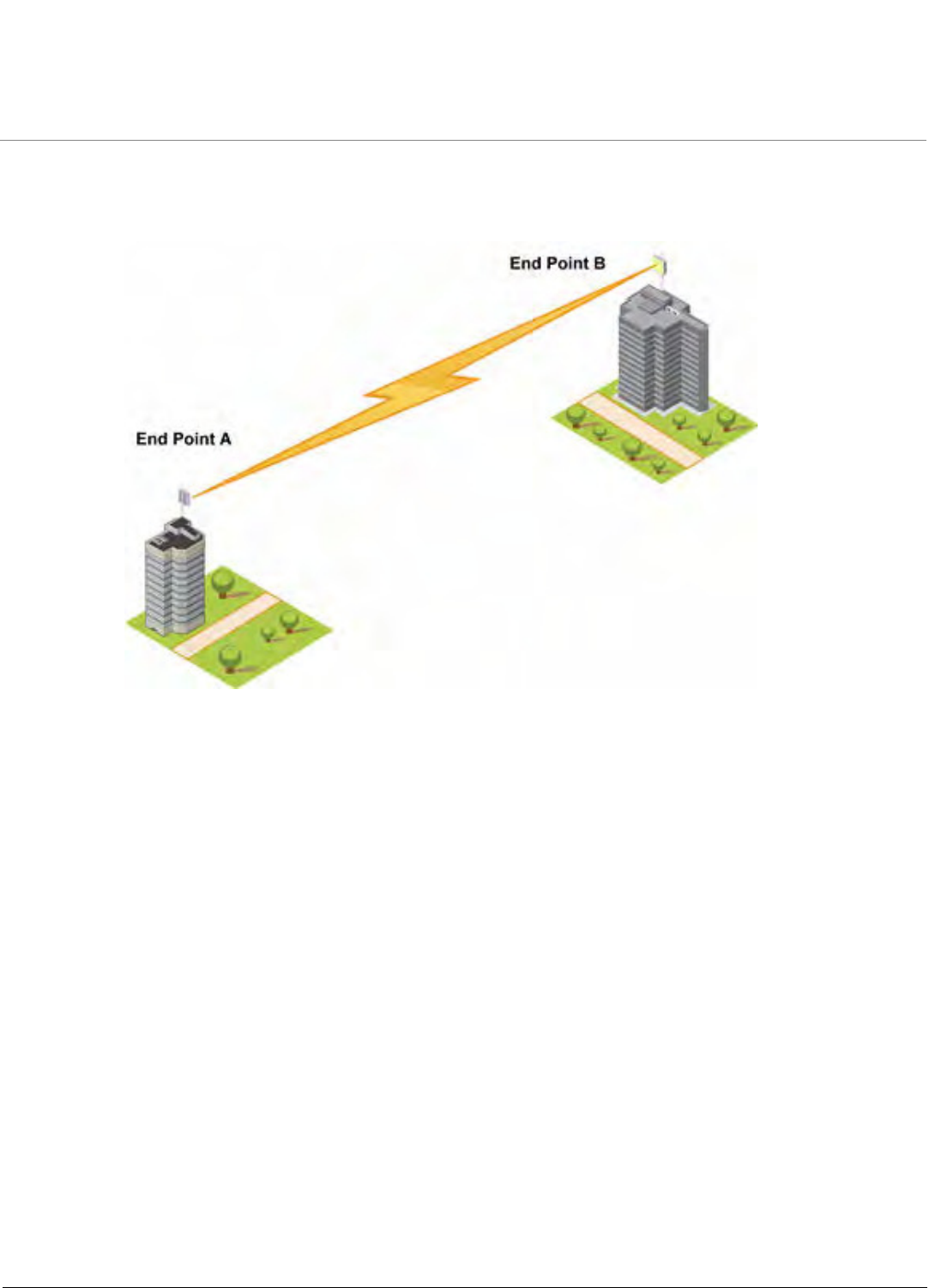
It is easy to set up a wireless point-to-point link as depicted in the following figure. Each device is set up as either an End Point
A or an End Point B.
Figure 1-1 Wireless Network Topology (Point-to-Point-Link)
With a point-to-point link, you can set up a connection between two locations as an alternative to:
•Leased lines in building-to-building connections
•Wired Ethernet backbones between wireless access points in difficult-to-wire environments.
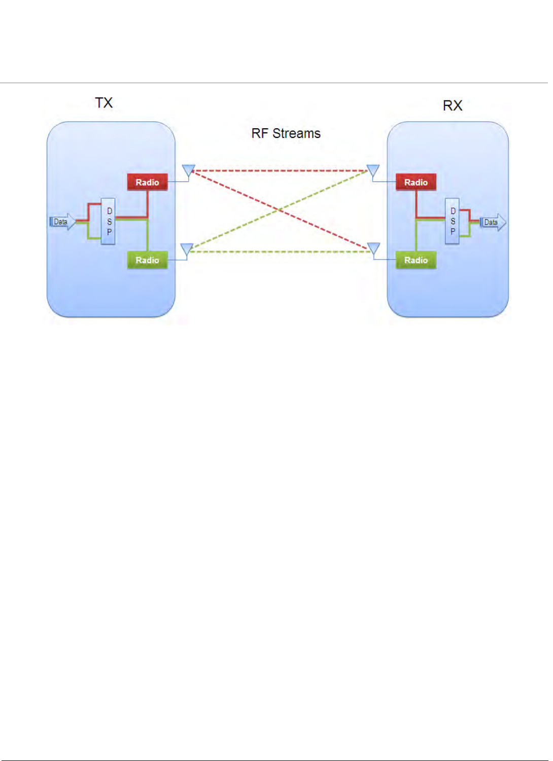
1.3 Multiple-Input-Multiple-Output (MIMO)
Multiple-Input-Multiple-Output (MIMO) is a smart antenna technology that offers tremendous performance gains for wireless
devices at relatively low cost. The underlying technology of the QB-8100 radios are based on a combination of MIMO and
OFDM. High performance OFDM-MIMO radio combination enhances robustness using multiple transmitters and receivers,
allowing the QB-8100 units to completely take advantage of this antenna technology. In real-world environments, signals
reflect from various objects to reach the receiving antenna, hence a signal follows different distances before being received.
This phenomenon is called multipath propagation and causes interference and fading in non-MIMO radios. On the receiver
side, having multiple receivers increases the amount of received power and also reduces multipath problems by combining
the received signals for each frequency component separately. Hence, MIMO significantly improves the overall gain.
Overview
Tsunami QB-8100 Series (100 Mbps/5 Mbps Models) Installation and Management Guide 13
Figure 1-2 2x2 MIMO

Overview
Tsunami QB-8100 Series (100 Mbps/5 Mbps Models) Installation and Management Guide 14
1.4 Management and Monitoring Capabilities
The network administrators can use the following management and monitoring interfaces to configure and manage the
Tsunami QB-8100 unit:
•Web Interface
•Command Line Interface
•SNMP Management
1.4.1 Web Interface
The Web interface (HTTP) provides easy access to configuration settings and network statistics from any computer on the
network. You can access the Web interface over your network, over the Internet, or with an Ethernet cable connected directly
to your computer’s Ethernet port. See Logging in to the Web Interface for more information.
1.4.2 Command Line Interface
The Command Line Interface (CLI) is a text-based configuration utility that supports a set of keyboard commands and
parameters to configure and manage the QB-8100 devices. You can enter command statements composed of CLI commands
and their associated parameters. You can enter commands from the keyboard for real-time control or from scripts that
automate configuration. See the Tsunami QB-8100 Reference Manual for more information about the Command Line
Interface.
1.4.3 SNMP Management
In addition to the Web interface and the CLI, you also can use Simple Network Management Protocol (SNMP) to manage and
configure the QB-8100 devices. Note that this requires an SNMP manager program (sometimes called MIB browser) or a
Network Manager program using SNMP. The devices support several Management Information Base (MIB) files that describe
the parameters that can be viewed and configured using SNMP:
1. PXM-SNMP.mib (Enterprise MIB)
2. RFC-1213.mib (MIB-II)
3. RFC-1215.mib (Trap MIB)
4. RFC-2790.mib (HOST-RESOURCES-MIB)
5. RFC-2571.mib (SNMP-FRAMEWORK-MIB)
6. RFC-3412.mib (SNMP-MPD-MIB)
7. RFC-3414.mib (SNMP-USER-BASED-SM-MIB)
The PXM MIB files are available on the Proxim Web site. You must compile one or more of these MIB files into your SNMP
program’s database before you manage your device using SNMP. See the documentation that came with your SNMP manager
for instructions about how to compile MIBs.
NOTE: When you update the software in the device, you must also update the MIBs to the same release. Because the
parameters in the MIB may have changed, you will not otherwise have full control over the features in the new
release.
The enterprise MIB (PXM-SNMP.mib) defines the Read and Read/Write objects you can view or configure using SNMP. These
objects correspond to most of the settings and statistics that are available with other management interfaces. See the
enterprise MIB for more information. The MIB can be opened with any text editor, such as Microsoft Word, Notepad, and
WordPad. See SNMP Parameters in the Services: Configuring the Passwords section.

Overview
Tsunami QB-8100 Series (100 Mbps/5 Mbps Models) Installation and Management Guide 15
IMPORTANT!
Using a serial connection, you can access the CLI of the device through a terminal emulation program,
such as HyperTerminal. (See “HyperTerminal Connection Properties” in the Tsunami QuickBridge 8100
Reference Manual.)
For all other modes of connection, you will need the IP address of the device to use the Web Interface,
SNMP, or the CLI via telnet.
CAUTION!
For Regulatory Information and latest product updates, including firmware and the MIBs, Proxim
recommends visiting the Proxim Support site at http://support.proxim.com.
IMPORTANT!
This user guide discusses installing the device and managing it using the Web interface only. For
information on managing the device via the CLI, see the Tsunami QuickBridge 8100 Reference Manual.

Tsunami QB-8100 Series (100 Mbps / 5 Mbps Models) Installation and Management Guide 16
2
Installation and Initialization
This chapter describes the steps required to install and mount the QuickBridge 8100 Series units. If you are already familiar
with this type of product, refer to the Tsunami QB-8100 Quick Installation Guide for streamlined installation procedures.
This chapter covers the following topics:
•Hardware Overview
•Product Package
•Installation Procedure
–Step 1: Plan for Installation
–Step 2: Choose a Location
–Step 3: Gather Required Tools
–Step 4: Unpack the Product Package
–Step 5: Assemble the Cable
–Step 6: Mount the Unit
–Step 7: Plug in the Cables
–Step 8: Ground the Unit
–Step 9: Power on the Unit
–Step 10: View LEDs
•Initialization
–ScanTool
–Setting the IP Address with ScanTool
•Logging in to the Web Interface
•Factory Default Configuration
Installation and Initialization
Tsunami QB-8100 Series (100 Mbps/5 Mbps Models) Installation and Management Guide 17
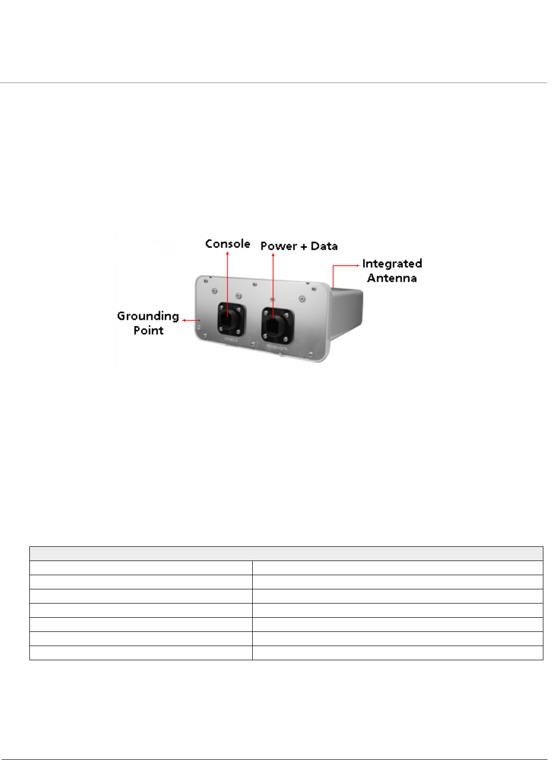
2.1 Hardware Overview
The Tsunami QB-8100 Series (100 Mbps/5 Mbps Models) is a full-featured outdoor QuickBridge Endpoint that contains a high
power radio unit in plastic enclosure with dual polarized, high gain performance, integrated antenna.
The unit is designed to be mounted to a pole of 1.25” - 3” diameter (not included) using the supplied pole mount bracket
accessories (P/N 909-00001). An optional universal wall mounting bracket is also available from Proxim (P/N 77537); this kit is
designed to mount directly to a flat surface such as a roof, wall, or under an eave.
The QB-8100 unit has an ethernet port with auto-sensing 10/100 BASE-T with configurable Tx Modes and Speeds. The unit is
powered through Power-over-Ethernet via a PoE injector, and is equipped with bi-color LEDs on the ethernet connector.
Figure 2-1 QB-8100 Hardware
2.1.1 Power-over-Ethernet
The QB-8100 unit is equipped with a Power-over-Ethernet (PoE) injector module which provides power through a PoE injector.
Using PoE injector, you can provide electricity and wired connectivity to the unit over a single Category5 cable.
•The PoE injector integrated module receives 48 VDC over a standard Cat5 Ethernet cable.
•Maximum power supplied to the QB-8100 unit is 19 Watts. The units typically draw less than 13.8 Watts.
•You must have a PoE injector connected to the network to use PoE. The injector is not a repeater and does not amplify
the Ethernet data signal.
•If connected to a PoE DC Injector and an AC power supply simultaneously, the radio draws power from PoE.
•The cable length between the PoE DC Injector and the radio should not exceed 100 meters (approximately 325 feet).
NOTE: The total length of cabling between the PC and the QuickBridge units cannot exceed 100 meters, which
includes both the cable from the PC to the power injector and the cable from the power injector to the QuickBridge
unit. Due to DC power requirements, the maximum cable length between the power injector and the QuickBridge
units is 75 meters.
Recommended Cable
Function Power (DC) and Ethernet connection
Type Cat5 UV-shielded and outdoor-rated
Impedance 100 ohms
Recommended cables STP, 24 AWG, UL rated
Maximum Distance 330 feet / 100 meters
Connector type, device end Shielded RJ45 female, weatherized using weatherproof connector
Connector type, power & Ethernet adapter end Shielded RJ45
Installation and Initialization
Tsunami QB-8100 Series (100 Mbps/5 Mbps Models) Installation and Management Guide 18
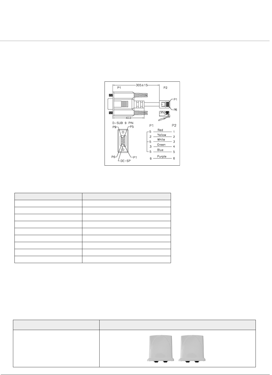
2.1.2 Serial Connection
The serial connection is made with an RJ11 to DB9 connector (also referred to as a “dongle”). Connect the RJ11 end to the
unit and connect the serial (DB9) end to your PC to align the antenna and to enter CLI commands.
See the following figure:
Figure 2-2 Serial Components
The connections are as follows:
2.2 Product Package
The product’s shipping boxes should be left intact and sheltered until arrival at the installation site. Carefully unpack the
QuickBridge 8100 Series (100 Mbps/5 Mbps Models) shipment and check for any shipping damage or missing parts.
Each shipment includes the items listed in the following table. Verify that you have received all parts of the shipment.
NOTE: Cables are not supplied with the unit.
D-Shell RJ11
1NC
22
34
4NC
5 1 + 3 + 5
66
7NC
8NC
9NC
What’s in the Kit Image
Units
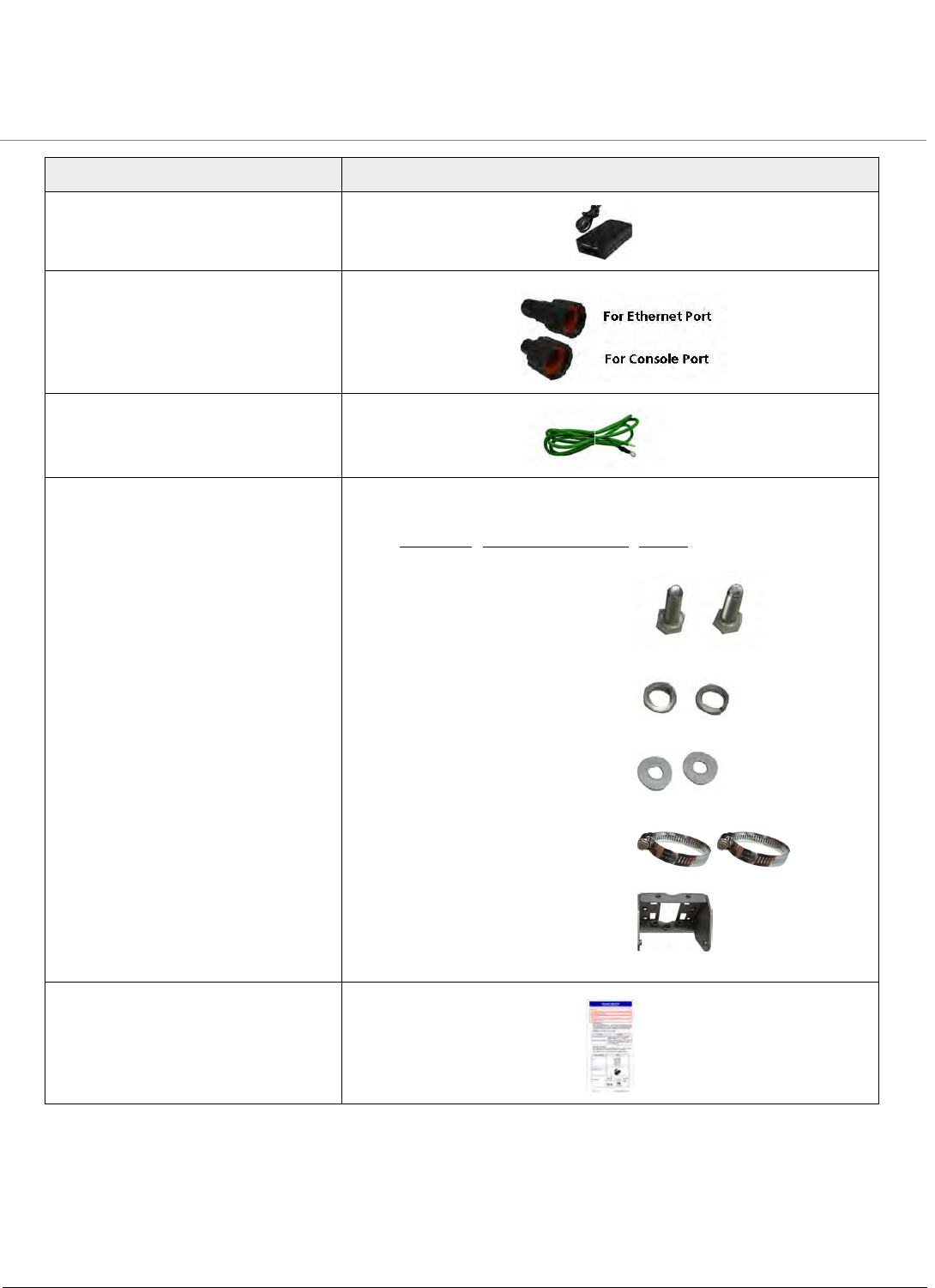
Installation and Initialization
Tsunami QB-8100 Series (100 Mbps/5 Mbps Models) Installation and Management Guide 19
Power Injector & Power Cord
Connector Weather Proofing
Kit
Grounding Kit
Pole Mounting Kit and Hardware The mounting kit includes the following:
Quick Installation Guide
What’s in the Kit Image
Quantity Component Name Image
2 ea. M6-16 Screw
2 ea. M6 Spring Washer
2 ea. M6 Plain Washer
2 ea. Hose Clamp
1 ea. Mounting Bracket

Installation and Initialization
Tsunami QB-8100 Series (100 Mbps/5 Mbps Models) Installation and Management Guide 20
2.3 Installation Procedure
This section describes the procedures to install and mount the QB-8100 unit. If you are already familiar with this type of
product, you can use the Quick Install Guide for streamlined installation procedures.
NOTE: Equipment is to be used with, and powered by, the power injector provided with the product package or by a
power injector that meets the following requirements:
–UL-Listed/ITE (NWGQ)
–Limited Power Source Output per UL/IEC 60950
–CE-marked
–Approved for Power-over-Ethernet
–Rated output, 48 VDC/0.40 A
See the following steps for installation instructions:
Step 1: Plan for Installation
There are several planning factors to be considered before installing the QuickBridge 8100 unit. In addition to selecting the
installation site, you should do the following:
Calculate:
•Required RSL and fade margin to achieve availability objectives
•Required path availability
•Anticipated Multi-Path Reflection Points
Determine:
•System Frequency Plan
•Required Transmission Line Types and Lengths
IMPORTANT
This device must be installed by a trained professional, value added reseller, or systems integrator who is
familiar with RF planning issues and the regulatory limits.
CAUTION!
Heed all the WARNINGS. Follow all the instructions. Do not defeat the safety purpose of the grounding.
Only use attachments/accessories specified by the manufacturer.
CAUTION!
There are no user-serviceable parts inside. All services must be performed by qualified personnel.
CAUTION!
For Regulatory Information and latest product updates, including firmware and the MIBs, Proxim
recommends visiting the Proxim Support site at http://support.proxim.com

Installation and Initialization
Tsunami QB-8100 Series (100 Mbps/5 Mbps Models) Installation and Management Guide 21
Plan for:
•Device’s continuous power consumption needs
•Lightning protection and system grounding
•Hardware mounting
•Cable installation including egress
•Pre-testing equipment (back-to-back test procedure)
Step 2: Choose a Location
To make optimal use of the device, you must find a suitable location to install the hardware. The range of the radio device
largely depends upon the position of the antenna. Proxim recommends you do a site survey, observing the following
requirements, before mounting the hardware.
•The location must allow easy disconnection of power to the radio if necessary.
•Ensure free flow of air around the hardware.
•The radio device must be kept away from vibration and excessive heat.
•The installation must conform to local regulations at all times.
Step 3: Gather Required Tools
You should have the following tools available before installing the QuickBridge 8100 units:
•Phillips (cross-tip) screwdrivers
•Large blade standard screwdriver
•Spanner 10
•Wire crimpers (if using connectors that are not pre-made)
•Weatherproofing material for sealing external connectors (such as butyl tape)
NOTE: The total length of cabling between the PC and the QuickBridge units cannot exceed 100 meters, which
includes both the cable from the PC to the power injector and the cable from the power injector to the QuickBridge
unit. Due to DC power requirements, the maximum cable length between the power injector and the QuickBridge
units is 75 meters.
Step 4: Unpack the Product Package
1. Unpack the device and accessories from the shipping box.
2. Note the Ethernet and MAC addresses of the unit as well as the serial number. These addresses may be used when
configuring the unit.
NOTE: The serial number is required to obtain support from Proxim. Keep this information in a safe place.
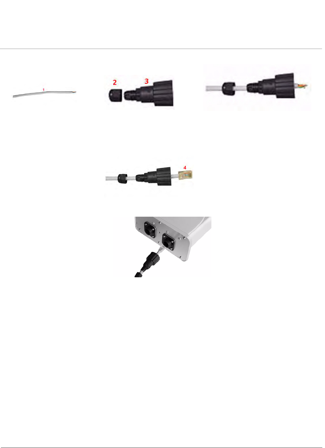
Step 5: Assemble the Cable
To assemble the ethernet cable and weather proof the RJ45 connector,
Installation and Initialization
Tsunami QB-8100 Series (100 Mbps/5 Mbps Models) Installation and Management Guide 22
1. Slide the lock nut (3) and sealing cap (2) over the bare end of a Cat5 ethernet cable (1) as shown in figure below:
2. Terminate the Cat5 ethernet cable and crimp it with a standard RJ-45 connector (4). Tighten the sealing cap and lock
the nut.
3. Insert the assembled ethernet cable into the POWER + DATA port of the QB-8100 unit.
Figure 2-3 Assembled Cable with the Unit
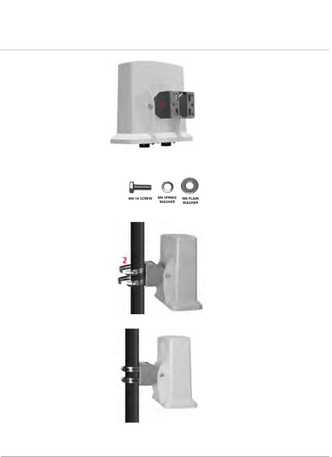
Step 6: Mount the Unit
QB-8100 Units must always be mounted with all access ports of the integrated antenna pointed straight down to achieve
horizontal and vertical polarization.
To pole mount the QB-8100 unit, perform the following steps:
1. Ensure that the pole intended for installation is securely attached to a solid base.
2. Attach the mounting bracket (1) to QB-8100 unit with the provided screws and washers as shown below:
Cat 5 cable with bare end Lock nut and sealing cap Lock nut and sealing cap with the Cat 5 cable
Installation and Initialization
Tsunami QB-8100 Series (100 Mbps/5 Mbps Models) Installation and Management Guide 23
NOTE: Slide the M6-16 screw through the M6 Spring washer first and then through M6 plain washer. Misplacement of
the washers may cause damage to the enclosure.
3. Slide the hose clamps (2) through the mounting bracket and place the hose clamps around the pole as shown below:
4. Insert the end of the hose clamps into the fastening clip and tighten the screw as shown below:
NOTE: Do not over tighten the screws at this stage, as the unit may need adjustment to obtain good signal strength.
An optional universal wall mounting kit bracket is also available from Proxim (P/N 77537); this kit is designed to mount the
unit directly to a flat surface such as a roof, wall, or under an eave.
Installation and Initialization
Tsunami QB-8100 Series (100 Mbps/5 Mbps Models) Installation and Management Guide 24
Step 7: Plug in the Cables
1. Plug one end of Cat5 Ethernet cable (5.5 mm/.217 in OD maximum; not supplied) into the Ethernet (RJ45) jack of the
Ethernet interface inside the unit enclosure. Ensure that the cable connector is latched securely. You can hear a click
sound when the cable connector latches into the jack, then tighten the sealing nut by hand.
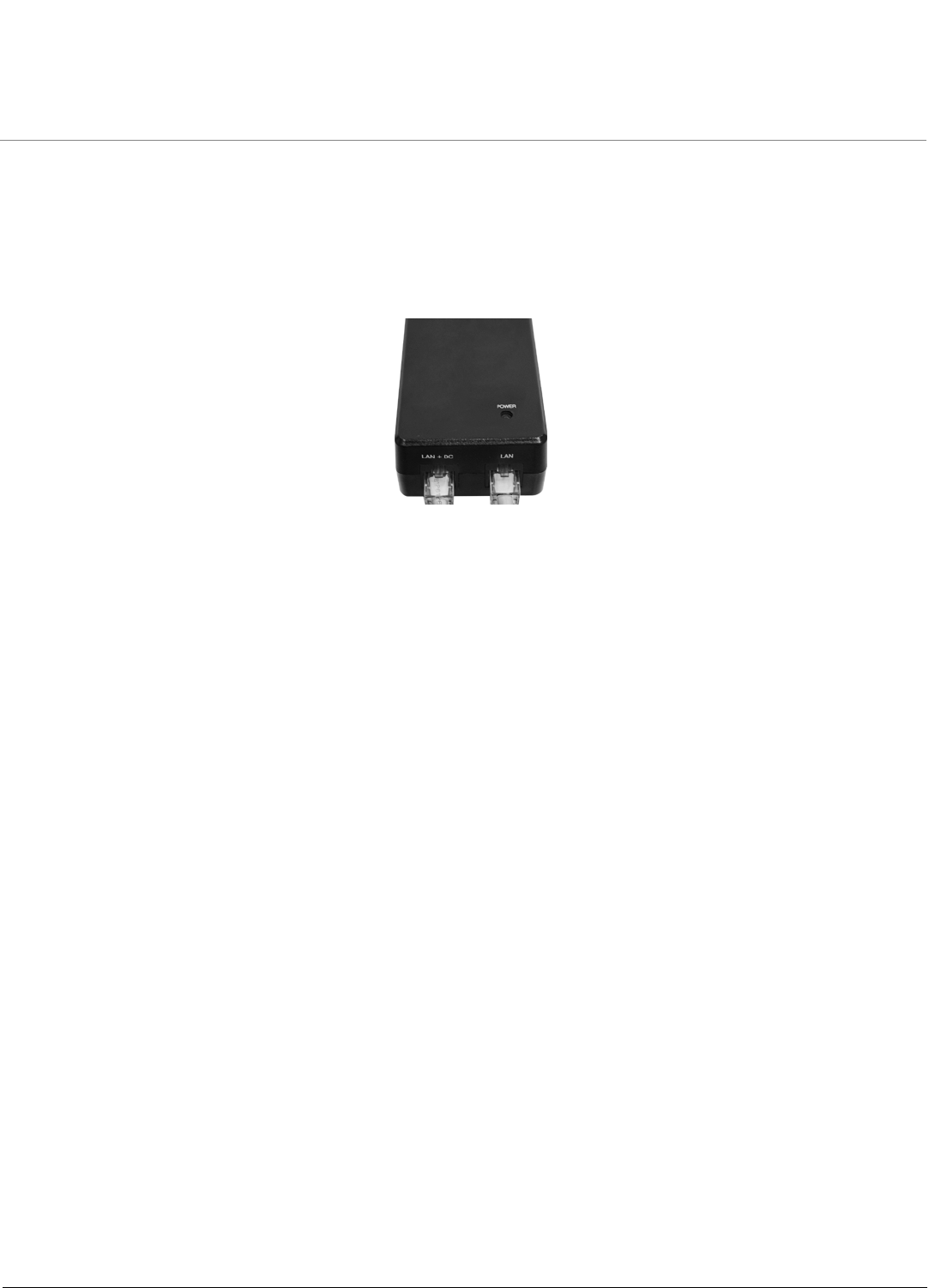
2. Connect the other end of the Cat5 cable to the “LAN+DC” port on the power injector.
NOTE: Proxim recommends to use the supplied PoE injector.
Figure 2-4 PoE Injector
WARNING: Connect network devices only into the “LAN” port of the Power injector. The “LAN+DC” port is
meant to power the QB-8100 unit.
3. To connect the QB-8100 unit directly to a PC, connect an Ethernet cable between the network interface card in the
PC and the RJ45 “LAN” port on the power injector.
4. To connect the QB-8100 unit through a hub or a switch to a PC, connect an Ethernet cable between the network
interface card in the PC and the hub. Connect another ethernet cable between the hub and the RJ45 “LAN” port on
the PoE injector.
NOTE: The unit auto-detects the cable type so straight or crossover ethernet cable can be used, provided the device at
the termination end has auto detection capability.
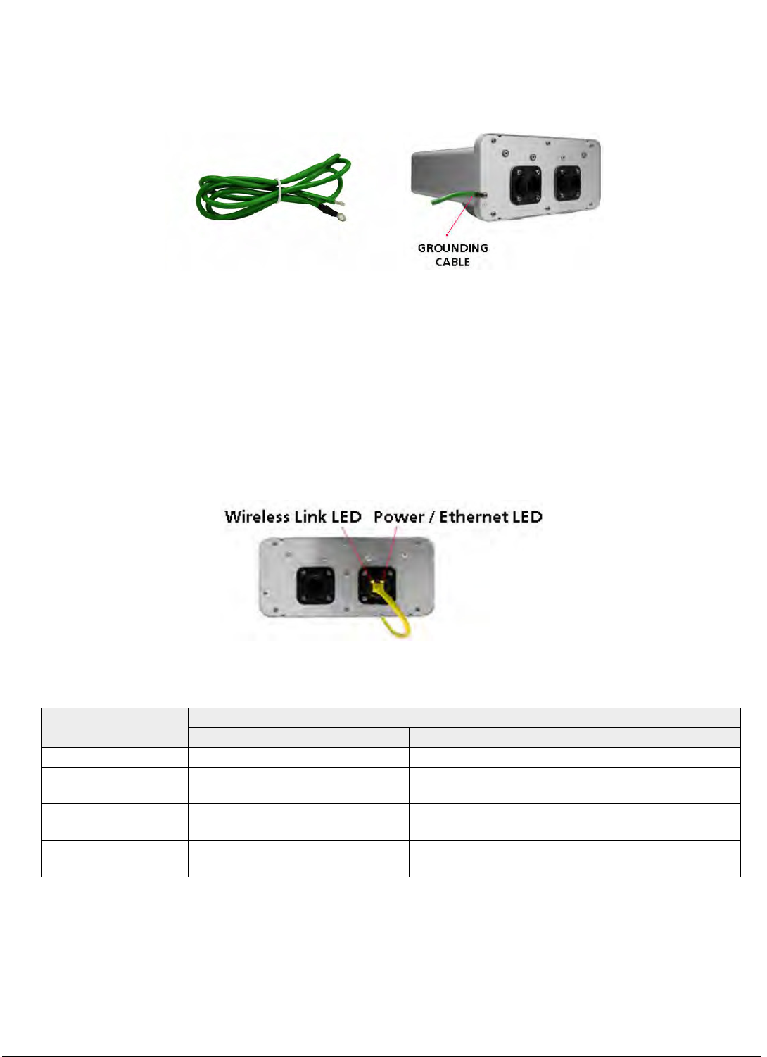
Step 8: Ground the Unit
To ensure proper grounding, use the ground point which is situated at the bottom corner of the unit and the grounding screw
(M3 thread size) provided to attach a ground wire of at least 12 AWG stranded to the unit. It is important that the following
ground guidelines are followed during installations:
1. Connect one end of the grounding cable to the QB 8100 unit as shown in the figure below and the other end to the
closest earthing system point at the installation.
2. Cut any extra ground wire length when finished connecting it to the single point earth ground.
3. Avoid sharp bends and never loop or coil up the ground wire, always connect it straight to ground.
4. A good earth ground impedance is less than 1.0 ohm.
5. Measure ground impedance at the point where the protector ground wire is connected and not at the ground rod.
6. Connect the protector ground wire and equipment ground (both power ground and telecomm ground) to a single
common ground.
7. Make sure all connections are fastened securely and are tight.
8. Never install during a storm and always follow your local safety codes.
Connect the grounding wire, which is supplied with the product package, to the grounding lug as shown below:
Installation and Initialization
Tsunami QB-8100 Series (100 Mbps/5 Mbps Models) Installation and Management Guide 25
.
Figure 2-5 Grounding the Unit
Step 9: Power on the Unit
Plug in the power cord into a power outlet after having connected the Power Injector and the Radio device using Cat5 cable.
There is no ON/OFF switch on the unit. To disconnect power, unplug the RJ45 connector from the “LAN+DC” port on the
power injector.
Step 10: View LEDs
When the device is powered on, it performs startup diagnostics. When startup is complete, the LEDs show the unit’s
operational state. The LEDs are available at the unit’s Ethernet connector inside the enclosure. You can see the LEDs through
the ethernet connector. The LEDs will not be visible when the weather sealing caps are installed.
Figure 2-6 View LEDs
The following table describes the status of LEDs and the corresponding operatinal state of the device:
NOTE: All the LEDs will blink during initialization.
LED State Ethernet Interface
Power/Ethernet LED Wireless LED
Off No Power Radio is not present or failed to detect
Amber No Application Image detected (In
Bootloader CLI/Scantool mode)
Power is on and unit detects Reload signal
Blinking Green Power is on and the Ethernet link is
down
Radio is detected but wireless link has not been
established yet
Solid Green Power is on and the Ethernet link is
up
Radio is detected and wireless link has been
established

Installation and Initialization
Tsunami QB-8100 Series (100 Mbps/5 Mbps Models) Installation and Management Guide 26
2.4 Initialization
Connecting to the device requires either:
•A direct connection with a serial RS-232 cable.
•A direct connection with an Ethernet cable or a network connection.
Connecting with the Ethernet cable allows you to use of the Web Interface and SNMP in addition to the CLI. Connecting with
a serial connection allows you to configure and manage the device with the CLI.
Using a serial connection, you can access the device through a terminal emulation program, such as HyperTerminal. (See
“HyperTerminal Connection Properties” in the Tsunami QB-8100 Reference Manual.)
For all other modes of connection, you will need the IP address of the device to use the Web Interface, SNMP, or the CLI.
Because each network is different, an IP address suitable for your network must be assigned to the unit. You must have this IP
address to configure and manage the device through its Web Interface, SNMP, or Telnet/CLI. The device can use either a static
or dynamic IP address. The device obtains its IP address automatically through DHCP (dynamic IP address); or else, you must
set the IP Address manually (static IP address).
2.4.1 ScanTool
ScanTool is a software utility that runs on Microsoft Windows machines and is included in the installation CD-ROM within the
device package. Using ScanTool, the IP address assigned to the device can be obtained and, if required, can be changed to the
IP address that is appropriate for the network. The tool automatically detects the devices installed in the network segment,
regardless of IP address, and enables the configuration of each device’s IP settings.
To access the HTTP interface and configure the device, the device must be assigned an IP address, which is valid on its
Ethernet network. By default, the device is configured with the IP address 169.254.128.132. In case of QB, by default, the
End Point A is configured as 169.254.128.132 and End Point B is configured as 169.254.128.131.
Using ScanTool, you can
•Launch the Web interface
•Scan devices which can respond to the Scantool
•Modify the assigned IP address
•Switch between the network adapters, if there are multiple network adapters in the system
NOTE: The user may need to disable Windows Farewell for ScanTool to function or to detect the radio.
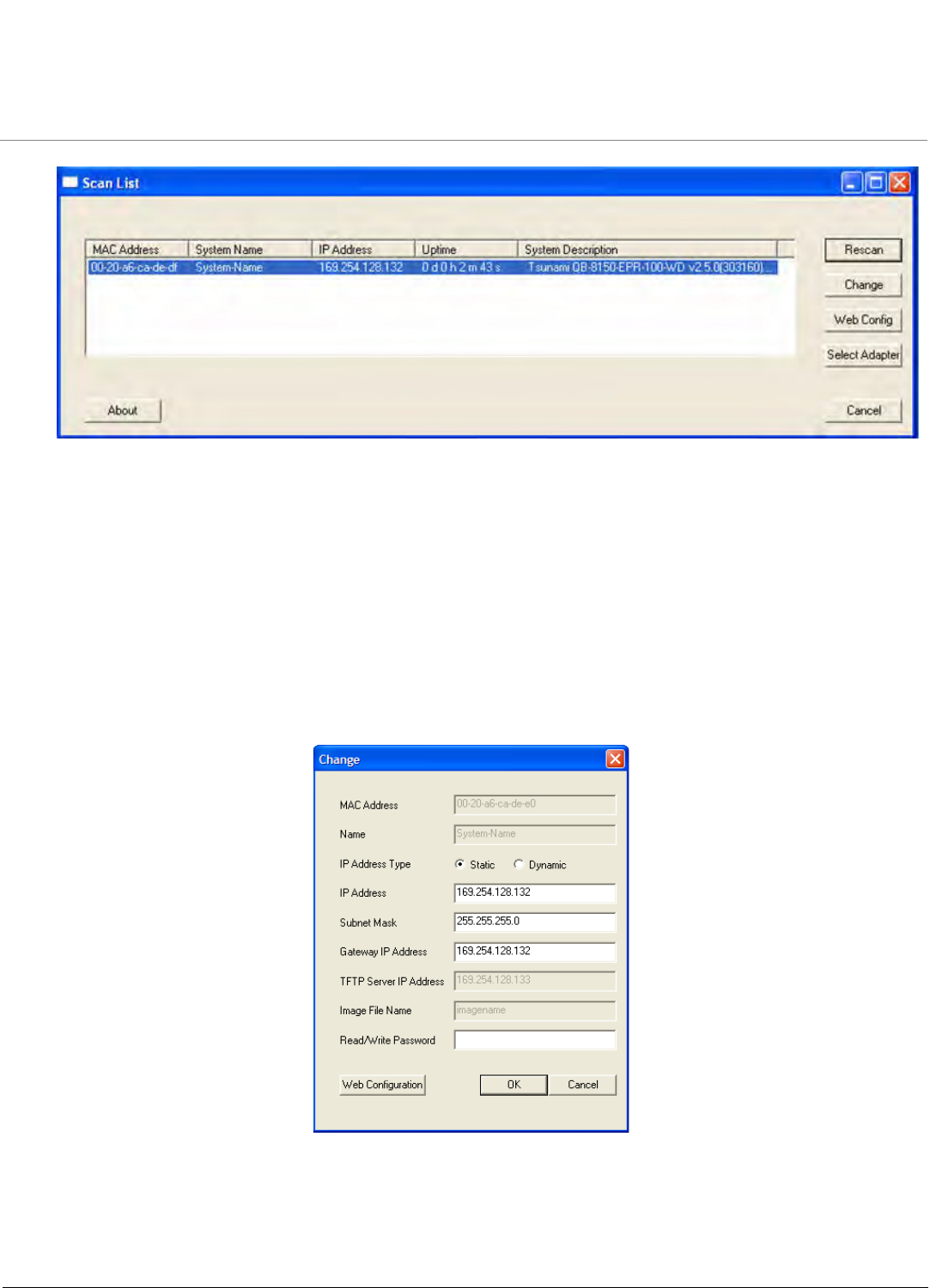
2.4.2 Setting the IP Address with ScanTool
To initialize the scan tool
1. Power up or reset the device.
2. Run ScanTool on a computer connected to the same LAN subnet as the device, or a computer directly connected to
the device with a cross-over Ethernet cable.
3. ScanTool scans the subnet and displays a list of detected devices in the Scan List.
Installation and Initialization
Tsunami QB-8100 Series (100 Mbps/5 Mbps Models) Installation and Management Guide 27
Figure 2-7 Scan List
NOTE: If your computer has more than one network adapter installed, it prompts you to select the adapter for the
ScanTool before the Scan List appears. If prompted, select the ethernet adapter and click OK. You can change your
adapter setting whenever necessary by clicking Select Adapter on the Scan List screen.
4. If your device details do not appear in the Scan List, click Rescan to update the display. Note that after rebooting the
device, it may take up to five minutes for the device details to appear in the Scan List. If the device details still do not
appear in the list, see Troubleshooting for suggestions.
2.4.3 Modifying the IP Address
Select the device details from the scan list and click Change. A Change screen appears as shown in the following figure. The
system automatically generates the MAC address, System Name, TFTP Server IP Address and Image File Name of the
unit. These details can be changed only through Web Interface.
Figure 2-8 Modifying the IP Address
Installation and Initialization
Tsunami QB-8100 Series (100 Mbps/5 Mbps Models) Installation and Management Guide 28
2.4.3.1 Assigning the IP Address Manually
1. Select the IP Address Type as Static and then enter the appropriate IP Address, Subnet Mask, and the Gateway IP
Address parameters.
2. Enter the SNMP Read/Write password in the Read/Write Password field. By default, it is public.
3. Click OK to save the details.
The device automatically reboots after clicking OK.
By clicking Rescan, verify whether the changes are applied or not. Then, click Web Configuration to open the web
interface.
2.4.3.2 Assigning the IP Address Dynamically
NOTE: Before setting the IP Address Type as Dynamic, ensure there is a DHCP server in the network.
1. Select the IP Address Type as Dynamic. The IP Address, Subnet Mask and the Gateway IP Address fields get
disabled.
2. Enter the SNMP Read/Write password in the Read/Write Password field. By default, it is public.
3. Click OK to save the details.
The device automatically reboots after clicking OK. By clicking Rescan, verify whether the changes are applied or not. Then,
click Web Configuration to open the web interface.
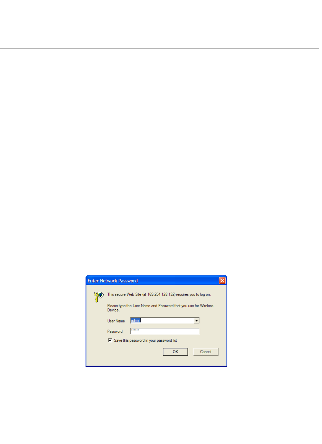
2.5 Logging in to the Web Interface
Once the device is connected to your computer, use a web browser to configure and monitor the device. Enter
http://169.254.128.132 (the device default IP address) in the address bar.
The user is prompted to enter the username and password to access the wireless device.
The default User Name is admin and Password is public.
Figure 2-9 Login Page
NOTES:
•Depending on the settings made during the device initialization, the IP address may be either a dynamic IP address
assigned by a network DHCP server or a static IP address which is manually configured. Refer to ScanTool for
information on how to determine the device’s IP address and manually configure a new IP address.
• If the connection is slow or unable to connect, use the Internet Explorer Tools option to ensure that you are not using
a proxy server for the connection.
Installation and Initialization
Tsunami QB-8100 Series (100 Mbps/5 Mbps Models) Installation and Management Guide 29
•If you are unable to log into the configuration pages by using default user name and password, please check with the
administrator or follow Forced Reload procedures.
•For security purposes, it is recommended to change Password from the default “public” immediately to restrict
unauthorized access to the device.
•If you enter wrong password consecutively for three times, the HTTP session will get disconnected.
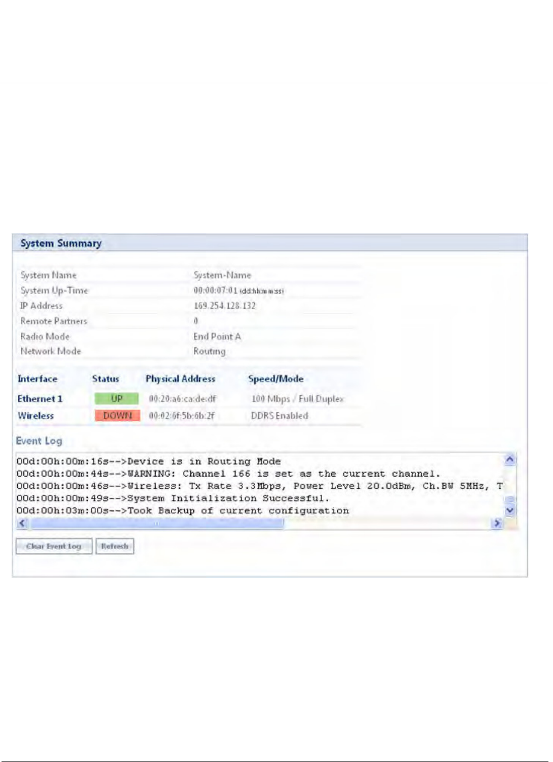
2.5.1 System Summary
Upon successful login, the system summary of the device is displayed on the screen. The system summary mainly displays the
general information and current state of the system, such as System Name, IP Address, Interface Status, and Event Log.
Figure 2-10 System Summary Page
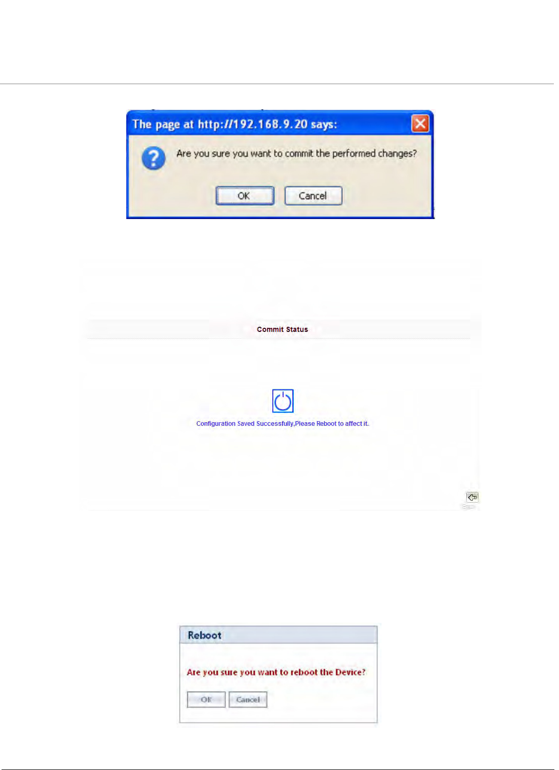
2.5.2 COMMIT Button
Commit button is used to apply the configuration changes into the unit. When changes are made to the configuration
parameters of the device, the changes will not take effect, until the COMMIT button is clicked. Some parameters may require
system reboot for the changes to take effect. On clicking COMMIT, the system evaluates all the configuration dependencies
and displays the configuration status.
Before applying commit, the system displays a confirmation message, as shown in the following figure:
Installation and Initialization
Tsunami QB-8100 Series (100 Mbps/5 Mbps Models) Installation and Management Guide 30
In some cases, upon successful COMMIT operation, a message “Please Reboot to take effect” appears as follows:
2.5.3 REBOOT Button
Reboot operation is required for any change in the key parameters to take effect. For example, settings such as configuring
the Radio Mode, IP Address, and Network Mode need reboot to take effect.
It is recommended that the device must be rebooted immediately after modifying a rebootable parameter. System displays a
confirmation window, wherein click OK.
Figure 2-11 Reboot

Installation and Initialization
Tsunami QB-8100 Series (100 Mbps/5 Mbps Models) Installation and Management Guide 31
NOTES:
•It is always mandatory to commit the changes before REBOOT, otherwise the changes will not take effect.
•The System Summary can be viewed by clicking HOME.
•The Event Log can be cleared by clicking Clear Event Log and can be refreshed by clicking Refresh.
An error message appears when a parameter is configured with inappropriate value. This error message prompts you to verify
your data or warns you to correct the pathway.

Installation and Initialization
Tsunami QB-8100 Series (100 Mbps/5 Mbps Models) Installation and Management Guide 32
2.6 Factory Default Configuration
Parameter Default
Network Mode Bridge
Routing Disabled
WORP Network Name MY_NETWORK
Password public
IP Address Assignment Type Static
IP Address 169.254.128.132
Subnet Mask 255.255.255.0
Registration Timeout 10
Network Secret public
SNMP Management Interface Enabled
Telnet Management Interface Enabled
HTTP Management Interface Enabled
MAC Authentication Disabled
Radius Authentication Disabled
Input Bandwidth Limit (in Kbps) As per license
Output Bandwidth Limit (in
Kbps)
As per license
QoS Unlimited BE
Filtering Disabled
DHCP Server Disabled
DHCP Relay Disabled
RIP Disabled
NAT Disabled

Tsunami QB-8100 Series (100 Mbps/5 Mbps Models) Installation and Management Guide 33
3
Basic Configuration
This chapter provides an overview of the basic configuration settings of Tsunami QB-8100 (100 Mbps/5 Mbps Models).
It covers the following topics:
•Country and Related Settings
•Dynamic Frequency Selection (DFS)
•Transmit Power Control
•Pairing the End Points or setting up a QB Link
•Virtual Local Area Networks (VLANs)
•Quality of Service (QoS)
•Basic Configuration Information

Basic Configuration
Tsunami QB-8100 Series (100 Mbps/5 Mbps Models) Installation and Management Guide 34
3.1 Country and Related Settings
The unit’s Advanced Configuration window provides a frequency domain field that automatically provides the allowed
bandwidth and frequencies for the selected country.
Units sold in the United States are pre-configured to scan and display only the outdoor frequencies permitted by the FCC. No
other country can be configured. Units sold outside of the United States support the selection of a country by the professional
installer using frequency domain.
NOTE: Non-US installers should not add an antenna system until the Country is selected, the device is rebooted, and
the proper power level is configured. The Transmit Power Control (TPC) feature can be used to reduce the power
when required.
The Dynamic Frequency Selection (DFS) feature is enabled automatically when you choose a country and band that require it.
Refer to Frequency Domains and Channels for information on which bands need DFS.
3.2 Dynamic Frequency Selection (DFS)
The Tsunami QB-8100 supports Dynamic Frequency Selection (DFS) for FCC, IC, and ETSI regulatory domains per FCC Part 15
Rules for U-NII devices, IC RSS-210, and ETSI EN 301-893 regulations, respectively. These rules and regulations require that the
devices operating in the 5 GHz band must use DFS to prevent interference with radar systems.
DFS is required for three purposes:
1. Radar avoidance both at startup and while operational. To meet these requirements, the End Point A scans
available frequencies at startup. If a DFS-enabled channel is busy or occupied with radar, the system will blacklist the
channel for a period of 30 minutes in accordance with FCC, IC, and ETSI regulations. Once fully operational on a
frequency, the End Point A actively monitors the occupied frequency. If interference is detected, the End Point A
blacklists the channel, logs a message and rescans to find a new frequency that is not busy and is free of radar
interference.
Radar detection is performed by both End Point A and End Point B. When an End Point B is set to a country/band in
which DFS is used, it passively scans all available channels upon startup looking for a End Point A that best matches its
connection criteria (such as End Point A Node System Name, Network Name, and Shared Secret). The End Point B
connects to the End Point A automatically on whatever frequency the End Point A has selected. Because of this
procedure, it is best to set up the End Point A and have it fully operational before installing the End Point B, although
this is not required. If an End Point A rescans because of radar interference, the End Point B loses its wireless link. The
End Point B waits for 30 seconds and if it finds that it could not receive the End Point A in this amount of time, it
rescans the available frequencies for an available End Point A.
2. Guarantee the efficient use of available frequencies by all devices in a certain area. To meet this requirement,
the End Point A scans each available frequency upon startup and selects a frequency based upon the least amount of
noise and interference detected. This lets multiple devices operate in the same area with limited interference.
3. Uniform Channel Spreading. To meet this requirement, the End Point A randomly selects operating channel from
the available channels with least interference. If the channel is occupied by radar, the device blacklists that channel
and scans other available channels for the one with least interference. This implements the Uniform Channel
Spreading requirement by automatically selecting the channel with least interference.
NOTE: If the Preferred Channel is configured, the device begins by scanning that channel. This allows the installer to
manually select a channel with least interference from a channel plan.
End Point A
Dynamic Frequency Selection (DFS) is enabled automatically based on the selected frequency domain. The device selects a
channel to operate as follows:

Basic Configuration
Tsunami QB-8100 Series (100 Mbps/5 Mbps Models) Installation and Management Guide 35
If ACS is disabled, during initialization, the device selects the Preferred Channel to be the operational channel. If ACS is
enabled, during initialization, the device scans all the channels in the configured frequency domain and selects the channel
with the best RSSI to be the operational channel.
Once the operating channel is selected, the device scans the channel for radar presence for a duration of Channel Wait Time.
If no radar is detected, the device starts operating in that channel. If radar is detected, the channel is blacklisted for 30
minutes and a different channel is selected. To select the next operational channel, the device scans all non-blacklisted
channels and selects the channel with best RSSI.
At any point of time, if Radar is detected on the current operating channel, the device blacklists that channel and scans all
non-blacklisted channels and selects the channel with best RSSI.
NOTE: Scanning is performed only on the frequencies allowed in the regulatory domain of the frequency/band
selected when it is required for radar detection and avoidance.
End Point B
When not connected to the End Point A, the End Point B scans continuously for all the channels in the configured Frequency
Domain for the presence of End Point A. If suitable End Point A is found in a channel, the End Point B tries to connect to it.
NOTE: Since the device may need to scan for radar on multiple channels, you must allow a sufficient amount of time
for the units to start up. This is considerably longer than when the device is not using DFS. This is expected behavior.
The Startup time is within four minutes if no radar is detected, but up to one minute is added for every selected channel that
results in radar interference.
For detailed information on DFS, refer to Frequency Domains and Channels.
3.3 Transmit Power Control
Transmit Power Control is a manual configuration selection to reduce the unit’s output power. The maximum output power
level for the operating frequency can be found in the event log of the unit’s embedded software.
By default, the device transmits at the maximum output power that the radio can sustain for data rate and frequency
selected. However, with Transmit Power Control (TPC), you can adjust the output power of the device to a lower level in order
to reduce interference to neighboring devices or to use a higher gain antenna without violating the maximum radiated
output power allowed for your country/band. Also, some countries that require DFS also require the transmit power to be set
to a 6 dB lower value than the maximum allowed EIRP when link quality permits, as part of the DFS requirements.
NOTES:
•When the system is set to transmit at the maximum power, professional installers must ensure that the maximum
EIRP limit is not exceeded. To achieve this, they may have to add attenuation between the device and the antenna
when a high gain antenna is used.
•You can see your unit’s current output power for the selected frequency in the event log. The event log shows the
selected power for all data rates, so you must look up the relevant data rate to determine the actual power level.
•This feature lets you only to decrease your the output power of the device; you cannot increase the output power of
your device beyond the maximum the radio allows for your frequency and data rate.
3.4 Pairing the End Points or setting up a QB Link
If a QB-8100 link product is purchased, the devices will come with a factory pre-configuration for forming a secure link out of
the box. If you want to form a link manually, the following parameters have to be configured with the same values on both
End Points for forming a link.

Basic Configuration
Tsunami QB-8100 Series (100 Mbps/5 Mbps Models) Installation and Management Guide 36
First configure one End Point as End Point A and the other End Point as End Point B. The list of parameters that must be
configured for linking of End Point A and End Point B are:
•Network Name
•Network Secret
•Encryption (when used)
•Frequency Channel (when available)
•Channel Bandwidth
•Data Rate
See the description of these parameters and how to configure them in Basic Configuration Information.
3.5 Virtual Local Area Networks (VLANs)
Virtual Local Area Networks (VLANs) are logical groupings of network hosts. Defined by software settings, other VLAN
members or resources appear (to connected hosts) to be on the same physical segment, no matter where they are attached
on the logical LAN or WAN segment. They simplify allowing traffic to flow between hosts and their frequently- used or
restricted resources according to the VLAN configuration.
QB-8100 End Points are fully VLAN-ready; however, by default, VLAN support is disabled. Before enabling VLAN support,
certain network settings should be configured and network resources such as VLAN-aware switches should be available,
based on the type of configuration.
For details on how to configure VLAN parameters, refer to VLAN Configuration (Bridge Mode only).
3.6 Quality of Service (QoS)
NOTE: Quality of Service is configured on the End Point A.
The Quality of Service (QoS) feature is based on the 802.16 standard and defines the classes, service flows, and packet
identification rules for specific types of traffic. The main priority of QoS is to guarantee a reliable and adequate transmission
quality for all types of traffic under conditions of high congestion and bandwidth over-subscription.
For a complete discussion on QoS, see Quality of Service (QoS) Configuration.
There are already several pre-defined QoS classes, SFCs and PIRs available that you may choose from which cover the most
common types of traffic. If you want to configure something else, you start building the hierarchy of a QoS class by defining
PIRs; you define the QoS class by associating those PIRs to relevant SFCs with priorities to each PIR within each SFC. Qos can
be applied on standard 802.3 ethernet frames as well as PPPoE encapsulated frames.
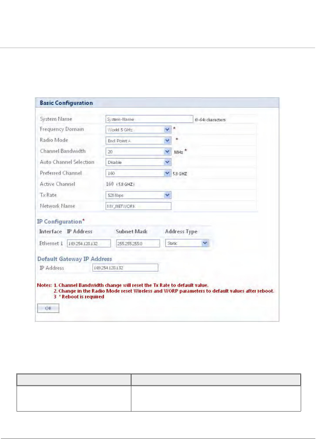
Basic Configuration
Tsunami QB-8100 Series (100 Mbps/5 Mbps Models) Installation and Management Guide 37
3.7 Basic Configuration Information
The BASIC CONFIGURATION Page in the Web-based Configuration Interface provides a one-place access to a minimum set of
configuration parameters to quickly set up a QuickBridge Point-to-Point link.
Figure 3-1: Basic Configuration
See the following table for Basic Configuration parameters and their descriptions:
Parameter Description
System Name This is the system name for easy identification of the End Point A
or End Point B. The System Name field is limited to a length of 64
characters.

Basic Configuration
Tsunami QB-8100 Series (100 Mbps/5 Mbps Models) Installation and Management Guide 38
Frequency Domain It specifies the country of operation, permitted frequency bands
and regulatory rules for that country/domain. Upon choosing a
frequency domain, the Dynamic Frequency Selection (DFS) and
Automatic Transmit Power Control (ATPC) features are enabled
automatically if the selected country and band has a regulatory
domain that requires it. The Frequency domain selection
pre-selects and displays only the allowed frequencies for the
selected country/domain.
NOTE: Units sold only in the United States are
pre-configured to scan and display the outdoor
frequencies permitted by the FCC. No other country
selections, channels, or frequencies can be configured.
Units sold outside of the United States support the
selection of a Country by the professional installer. If
you change the Frequency Domain, a reboot of the
unit is necessary for the upgrade to take place.
NOTE: On World units, if World 5 GHz is selected from
the Frequency Domain drop-down menu, any Channel
in the 5 GHz range are displayed for manual selection.
For a non US device, the default Frequency Domain selected is
World 5GHz. For more information on frequency domains, refer
to Frequency Domains and Channels.
Radio Mode It specifies the mode of operation of the Unit. The device
supports 2 types of modes, End Point A and End Point B,
synonymous to Master/Slave and Base/Satellite. For establishing a
link, configure one device as End Point A and other as
End Point B.
Channel Bandwidth It specifies the channel bandwidth. By default, it is set to 20 MHz.
40 MHz can be selected for higher throughputs depending on
the distance and signal quality. 5 and 10 MHz can be selected for
greater flexibility in spectrum selection.
Auto Channel Selection Enable or disable the auto channel selection for wireless interface.
If ACS is enabled on the End Point A, it scans all the channels and
selects the best channel at the start up. If ACS is enabled on the
End Point B, End Point B continuously scans all the channels till it
connects to an End Point A.
NOTE: ACS is enabled by default on End Point B.
Preferred Channel It displays a list of available channels in the specified frequency
domain. Configure this if you want to operate the device in a
specific channel.
NOTE: When DFS is active, the Device will automatically
pick a new channel when RADAR interference is
detected. Preferred channel is applicable only when
Automatic Channel Selection is disabled.
Parameter Description

Basic Configuration
Tsunami QB-8100 Series (100 Mbps/5 Mbps Models) Installation and Management Guide 39
Active Channel This will display the current active channel on which wireless
interface is operating. If you have enabled the auto channel
selection option or if the device moves to a different channel
because of radar detection, then this field displays the current
operating channel.
DDRS Status This parameter is displayed only when DDRS feature is enabled in
ADVANCED CONFIGURATION > Wireless > Interface 1 >
DDRS. For more details refer to DDRS.
Tx Rate This parameter represents the transmission data rate of the
device. Desired rate can be selected from the list of available Tx
rates.
NOTE: Configure the appropriate data rate based on
the signal level.
Network Name It is the name given to a network so that an End Point A and an
End Point B can mutually authenticate. End Point B can register to
End Point A, only if it has the same Network Name. The Network
Name can be 2 to 32 characters in length.
Ethernet IP Configuration
By default, the QuickBridge End Point is configured to operate in Bridge Mode. The parameters in this section
vary depending on the device’s operating mode, i.e., Bridge or Router. Because the QuickBridge is a
point-to-point system, Routing mode is not required for QuickBridge units. Configuring the unit in Routing
mode is not necessary.
IP Address Type • Select Static if you want to assign a static IP address to the
unit. Use this setting if you do not have a DHCP server or if you
want to manually configure the IP settings.
• Select Dynamic to have the device run in DHCP client mode,
which gets an IP address automatically from a DHCP server
over the network.
NOTE: The default Address Type is Static.
When the unit is in Bridge mode, only one IP address is required.
This IP address also can be changed with ScanTool (See Setting
the IP Address with ScanTool).
IP Address This parameter is configurable only if the IP Address Assignment
Type is set to Static. The default IP Address for End Point A is
169.254.128.132 and for End Point B is 169.254.128.131.
Subnet Mask The mask of the subnet to which the unit is connected (the
default subnet mask is 255.255.255.0). This parameter is
configurable only if the IP Address Assignment Type is set to
Static.
Gateway IP Address The IP address of the default gateway. This parameter is
configurable only if the IP Address Assignment Type is set to
Static. The default gateway IP Address is 169.254.128.132.
Parameter Description

Tsunami QB-8100 Series (100 Mbps/5 Mbps Models) Installation and Management Guide 40
4
Advanced Configuration
This chapter provides details about the Tsunami QB-8100 unit parameters and describes the procedures to configure them
using Web-based management interface. These parameters can also be configured using the other management interfaces
like SNMP and CLI.
The following topics are covered in this chapter:
•System Configuration
•Network Configuration
•Ethernet Properties Configuration
•Wireless Configuration
•Security Configuration
•Quality of Service (QoS) Configuration
•VLAN Configuration (Bridge Mode only)
•Filtering Configuration (Bridge Only)
•DHCP Configuration
•Routing Features Configuration
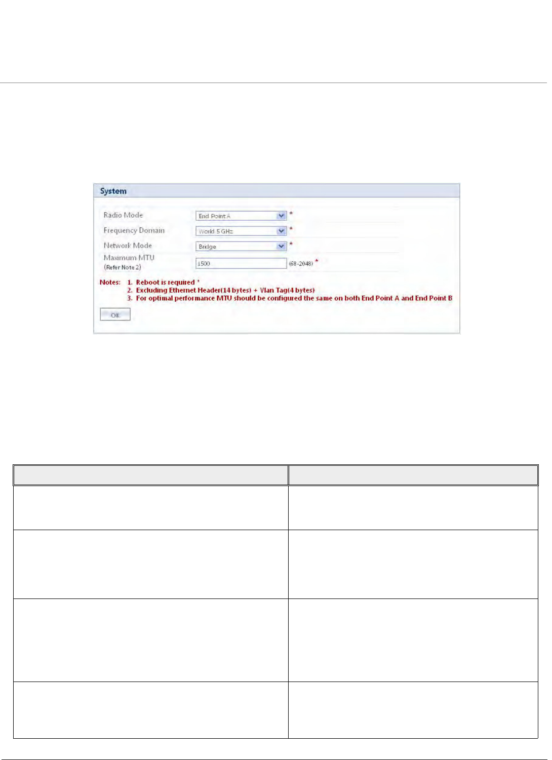
Advanced Configuration
Tsunami QB-8100 Series (100 Mbps/5 Mbps Models) Installation and Management Guide 41
4.1 System Configuration
The System screen allows you to configure the QB-8100 device as an End Point A or an End Point B, the frequency domain,
and the network mode as Bridge or Routing.
To configure the System
1. Click ADVANCED CONFIGURATION > System. The System screen is displayed as shown below:
Figure 4-1 System screen
2. From the Radio Mode drop-down menu, select either End Point A or End Point B.
3. From the Frequency Domain drop-down menu, select a frequency domain.
4. From the Network Mode drop-down menu, select either Bridge or Routing.
5. For the Maximum MTU field, enter the maximum MTU value.
6. Click OK.
The following table lists the System parameters and their descriptions:
Parameter Description
Radio Mode Radio mode specifies the mode of operation and
QB-8100 supports two types of modes, End Point A
and End Point B.
Frequency Domain A valid frequency domain must be set before the
device can be configured with any other parameters.
Selecting a frequency domain makes the device
compliant with the allowed frequency bands and
channels for that regulatory domain.
Network Mode The device can be configured in two network modes:
Bridge Mode and Routing Mode. The default network
mode is Bridge Mode.
Refer to Configuring IP in Bridge or Router Mode for
more information.
Active Network Mode This is a read-only parameter which shows current
operating network mode of the device. It is displayed
only when the newly configured Network mode differs
from the current Active Network mode.
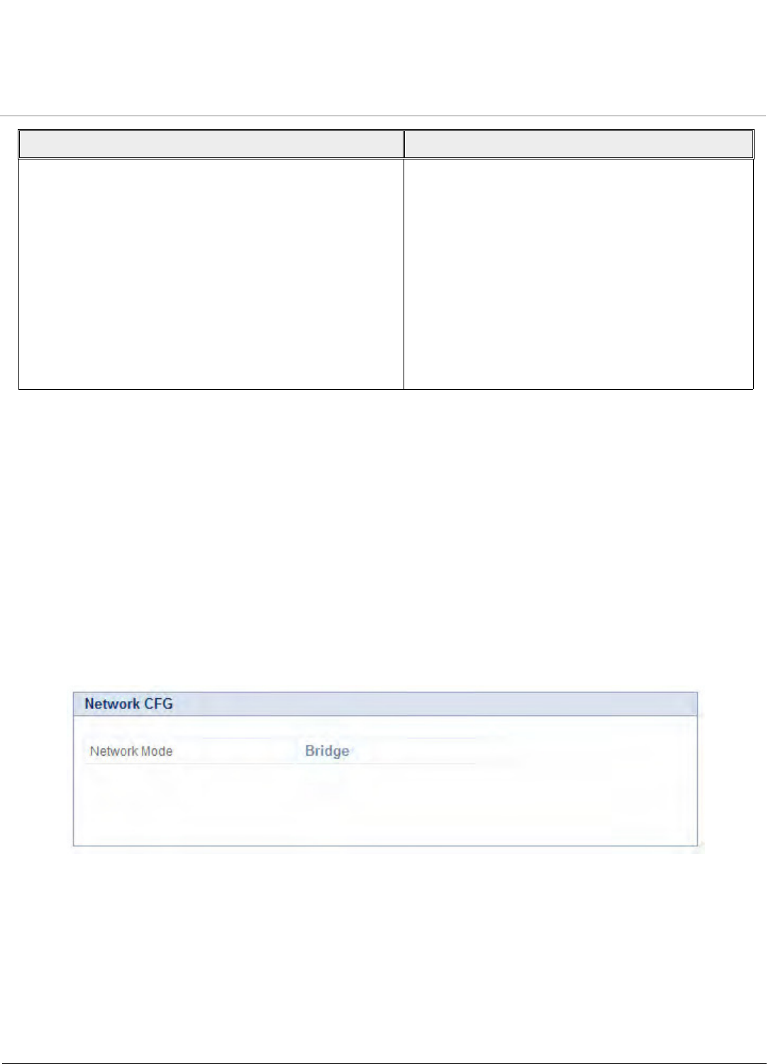
Advanced Configuration
Tsunami QB-8100 Series (100 Mbps/5 Mbps Models) Installation and Management Guide 42
NOTE: Click COMMIT and REBOOT after changing any system parameter.
4.2 Network Configuration
Based on the selected mode of operation, the IP settings vary. When the device is in Bridge mode, only a single IP address is
required; but for Routing mode, individual IP address are needed for each of the Ethernet and Wireless interfaces. In Bridge
mode, the IP address can be statically assigned or dynamically obtained through DHCP; whereas in Routing mode, only static
assignment is supported.
4.2.1 Configuring IP in Bridge or Router Mode
To view the network settings,
1. Click ADVANCED CONFIGURATION > Network.
If the device is configured in Bridge mode, the following screen appears:
Figure 4-2 IP Configuration in Bridge Mode
If the device is configured in Router mode, the following screen appears:
Maximum MTU This feature provides support for Ethernet frames with
more than 1,500 bytes of payload (MTU). It can be
configured with any value between 68 to 2048 bytes.
By default, its value is 1500.
NOTES:
• The “Max MTU” configured does not
include Ethernet Header (14 bytes) and
VLAN tag (4 bytes).
•For optimal performance, same value of
MTU should be configured on both End
Point A and End Point B.
Parameter Description
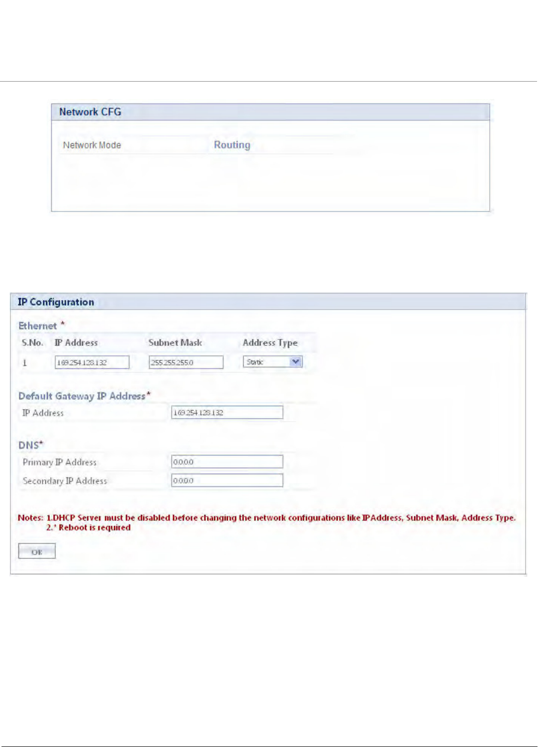
Advanced Configuration
Tsunami QB-8100 Series (100 Mbps/5 Mbps Models) Installation and Management Guide 43
Figure 4-3 IP configuration in Router mode
To configure the Network IP properties, click ADVANCED CONFIGURATION > Network > IP Configuration. The following
screen appears:
Figure 4-4 IP Configuration
1. Enter the appropriate parameters in the IP Configuration screen. See the following table that lists and describes the
parameters.
2. Click OK. The IP configuration takes effect only after Reboot.

Advanced Configuration
Tsunami QB-8100 Series (100 Mbps/5 Mbps Models) Installation and Management Guide 44
NOTE: Click COMMIT and then REBOOT for the changes to take effect.
Parameter Description
Ethernet
Address Type This field is applicable only if the Network mode on the System screen is
configured in Bridge mode. This parameter specifies whether the device network
parameters are to be configured through DHCP or to be assigned statically.
Select Dynamic to configure the device as a Dynamic Host Configuration Protocol
(DHCP) client. If Dynamic is selected, the device obtains the IP settings from a
network DHCP server automatically during the bootup. If you do not have a DHCP
server or if you want to manually configure the device’s IP settings, select Static
for the Address Type.
IP Address Enter the IP Address of the interface.
In Bridge Mode: When the Address Type is selected as Dynamic, this field
becomes read-only and displays the current IP address of the device.
If the device cannot obtain an address from a DHCP server, it displays the default
IP Address as 169.254.128.132 for End Point A and 169.254.128.131 for End
Point B.
In Routing Mode: For these interfaces, this field displays the default IP Addresses
as follows:
Ethernet interface: 169.254.128.132
Wireless interface: 169.254.130.132
Subnet Mask This parameter represents the subnet mask of the interface.
In Bridge Mode: When the Address Type is selected as Dynamic, this field
becomes read-only and displays the current subnet mask of the device.
If the device cannot obtain an address from a DHCP server, it displays the default
subnet mask as 255.255.255.0.
Default Gateway IP Address
Default Gateway IP
Address
This parameter represents the gateway IP Address of the device.
In Bridge Mode: When the Address Type is selected as Dynamic, this parameter
becomes read-only and displays the device’s current gateway IP Address that is
obtained through DHCP. If the device cannot obtain an address from a DHCP
server, the default gateway IP Address is 169.254.128.132. When Static IP
assignment is used, subnet of the default gateway should match with the subnet
of any one of the interfaces.
DNS
Primary DNS Specifies the IP Address of the Primary DNS Server.
Secondary DNS Specifies the IP Address of the Secondary DNS Server.
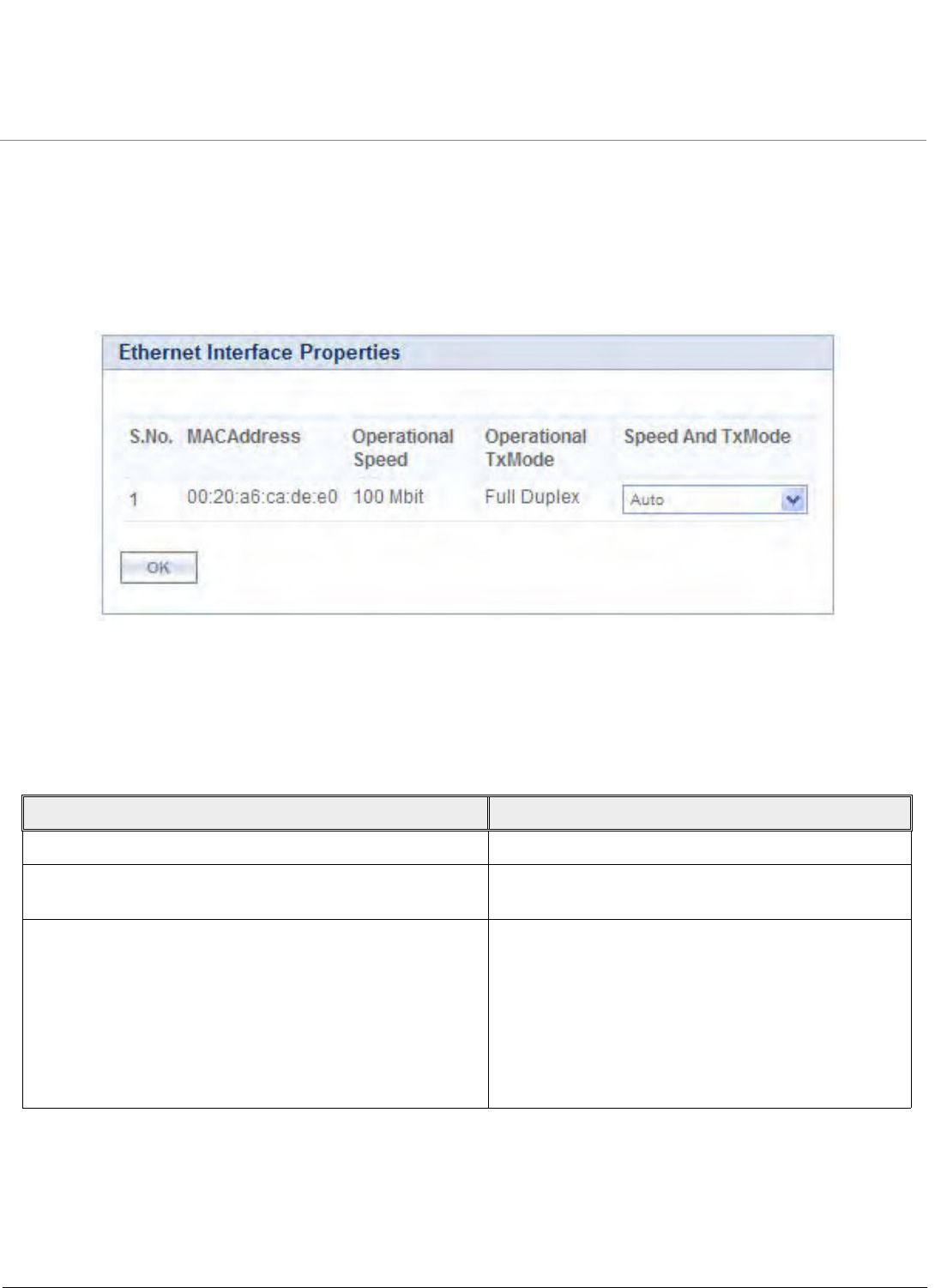
Advanced Configuration
Tsunami QB-8100 Series (100 Mbps/5 Mbps Models) Installation and Management Guide 45
4.3 Ethernet Properties Configuration
In the Ethernet Interface Properties screen, you can configure the Ethernet transmission properties. The recommended
settings are Auto for TxMode And Speed. The device supports a single ethernet interface Ethernet 1.
To configure the Ethernet Interface
1. Click ADVANCED CONFIGURATION > Ethernet. The Ethernet Interface Properties screen is displayed as shown
below.
Figure 4-5 Wireless Ethernet Properties
2. Enter the appropriate parameters in the Ethernet Interface Properties screen. See the following table that lists the
parameters and their descriptions.
3. Click OK and then click COMMIT.
Parameter Description
MAC Address Displays the MAC address of the Ethernet interface.
Operational Speed Displays the current operational speed of the Ethernet
interface. The speed can be 100 Mbps or 10Mbps.
Operational Tx Mode Displays the current operational transmit mode of the
Ethernet interface. There are 2 types of transmission
modes:
•Half Duplex: Allows one-way transmission at
a time. Only receive or transmit operations
can be performed at once.
•Full Duplex: Allows two-way transmissions
simultaneously.

Advanced Configuration
Tsunami QB-8100 Series (100 Mbps/5 Mbps Models) Installation and Management Guide 46
4.4 Wireless Configuration
The QB-8100 series of devices use a proprietary Wireless Outdoor Router Protocol (WORP). WORP offers services based on a
polling algorithm, specially designed for wireless outdoor networks. WORP is designed to minimize the number of packets
being sent over the air by incorporating several mechanisms, like super-packeting and piggy-back acknowledgment in order
to achieve maximum throughput possible in the outdoor conditions.
A WORP-based device provides two modes of operations for establishing a wireless link, End Point A and End Point B. Based
on the mode of operation at the interface, the respective parameters can be configured. The following sections describe the
configurations for End Point A and End Point B.
4.4.1 Configuring WORP Properties in End Point A Mode
To set the WORP properties
1. Click Advanced Configuration > Wireless > Interface1 > WORP. The WORP Configuration screen appears.
TxMode And Speed This parameter allows the user to select the speed and
mode based on the requirement for the corresponding
interface.
NOTE:
•Auto: Selects the best transmission mode
available when both sides are set to Auto.
•The recommended setting is Auto.
•In order to allow communication, the
transmitter and receiver should be
configured in same transmission modes.
•The maximum speed is measured as 100
megabits per second.
Parameter Description
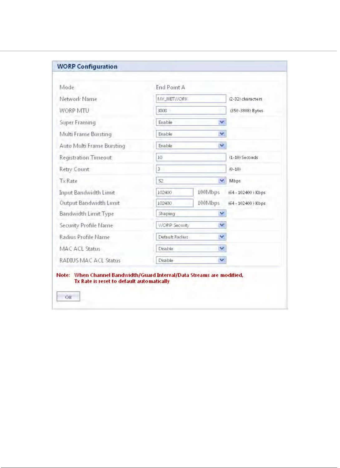
Advanced Configuration
Tsunami QB-8100 Series (100 Mbps/5 Mbps Models) Installation and Management Guide 47
Figure 4-6 Wireless Interface WORP
2. Enter the appropriate parameters in the WORP Configuration screen. See the following table for the descriptions of
the parameters.
3. Click OK.

Advanced Configuration
Tsunami QB-8100 Series (100 Mbps/5 Mbps Models) Installation and Management Guide 48
Parameter Description
Mode Specifies the radio mode in which the device is
configured.
Network Name It is the name given to a network so that an End
Point A and an End Point B can mutually
authenticate. End Point B can register to End Point A
only if it has the same Network Name. The Network
Name can be 1 to 32 characters in length.
WORP MTU WORP MTU (Maximum Transfer Unit) is the largest
size of the data payload in wireless frame that may
be transmitted. The MTU size can range from 350 to
3808 for High Throughput modes.
The default and maximum value of the WORP MTU
is 3808.
Super Framing Super Framing refers to the mechanism that enables
multiple Ethernet/802.3 frames to be packed in a
single WORP data frame. When the WORP MTU size
is configured larger than the Ethernet frame size,
then WORP constructs a super frame with size of
the WORP MTU configured and pack multiple
Ethernet frames. It results in reducing the number of
frames transmitted over wireless medium thereby
conserving wireless medium and increasing the
overall throughput.
Multi Frame Bursting To achieve higher throughput, WORP protocol
allows each side (End Point A or End Point B) to send
multiple data frames in sequence and treats it as a
single data frame. During Multi bursting sequence,
the receiver will not be allowed to interrupt the
sequence by sending any message. By default, this
feature is Enabled.
This parameter is configurable only on End Point A
and it turns this feature on (if enabled) or off (if
disabled) for both End Point A and End Point B.
When Multi Frame Bursting is enabled, the number
of frames transmitted for each polling cycle can be
configured as part of Quality of Service (QoS)
Configuration.

Advanced Configuration
Tsunami QB-8100 Series (100 Mbps/5 Mbps Models) Installation and Management Guide 49
Auto Multi Frame Bursting Select Enable or Disable from Auto Multi Frame
Bursting drop-down box. By default, Auto Multi
Frame Bursting is enabled.
NOTE: Auto Multi Frame Bursting is enabled
only if Multi Frame Bursting is
Enabled.
When Auto Multi Frame Bursting is disabled, the
number of packets per burst will be defined as in
the QoS Service Flow class used for communication.
When this feature is enabled, End Point A will
monitor which of the active QoS SF Classed has the
highest priority, and allow only that class to use
multi-frame bursting, all the rest SF Classes to use
only single frame per burst.
Registration Time-out It specifies the maximum duration for the
registration process to complete once End Point B
starts registering with End Point A. Default time is
10 seconds.
Retry Count This parameter specifies the maximum number of
times a data message is retransmitted, over the
wireless medium, if acknowledgement is not
received. By default, this parameter is set to 3.
DDRS Status This parameter is displayed only when DDRS feature
is enabled in ADVANCED CONFIGURATION >
Wireless > Interface 1 > DDRS. For more details
refer to DDRS.
Tx Rate This parameter represents the modulation rate at
which the packet will be transmitted from the
wireless device.
NOTE: The supported transmission rates
vary based on the Channel Bandwidth,
Guard Interval, and Number of Data
Streams parameters.
Input/Output Bandwidth Limit This parameter limits the data received on the
wireless interface and transmitted to the wireless
interface. Minimum of 64 Kbps to the maximum
value specified in the License File.
Parameter Description

Advanced Configuration
Tsunami QB-8100 Series (100 Mbps/5 Mbps Models) Installation and Management Guide 50
NOTE: Modifying any of End Point A parameters results in temporary loss of connectivity with the End Point B.
Bandwidth Limit Type This parameter specifies the action performed when
the traffic utilization exceeds the configured
input/output limits.
Policing: When the traffic utilization reaches the
configured limit, the excess traffic will be discarded.
Shaping: When the traffic utilization reaches the
configured limit, the excess traffic will be buffered
and sent at the rate specified in the Output
Bandwidth Limit.
Security Profile Name This parameter represents the security profile
currently used. The default Security Profile Name is
WORP Security. The Security Profile contains the
authentication and encryption methods used to
secure the connection between the End Point A and
End Point B. Refer to Security Configuration.
Radius Profile Name This parameter represents the radius profile
currently used. The radius profile contains the IP
address details of the RADIUS server. Refer to
Configuring the Radius Server Profile (End Point A
Only).
MAC ACL Status This parameter is used to enable or disable the MAC
Access Control List (ACL). When enabled, the End
Point A checks the ACL to allow or deny access to
the End Point B.
This option is available only in End Point A mode.
Radius MAC ACL Status This parameter is used to enable authentication
using RADIUS server. When enabled, the End Point
A contacts the RADIUS server for authenticating the
End Point B during the registration process. This
option is available only in End Point A mode.
Parameter Description

Advanced Configuration
Tsunami QB-8100 Series (100 Mbps/5 Mbps Models) Installation and Management Guide 51
4.4.2 Configuring WORP Properties in End Point B Mode
When the device is in End Point B mode, only End Point B-related configuration settings are displayed. Refer to Configuring
WORP Properties in End Point A Mode.
Refer to Configuring WORP Properties in End Point A Mode for description of rest of the parameters.
To apply the configured properties to the device, click COMMIT.
NOTE:
•Modifying the WORP parameters of either End Point A or End Point B may result in temporary loss of the link.
•When you modify WORP parameters and click COMMIT, it may result in brief interruption of service.
4.4.3 Wireless Interface Properties
In the Wireless Interface Properties screen, you can configure the properties of wireless interface.
To configure the wireless interface properties
1. Click ADVANCED CONFIGURATION > Wireless > Interface 1 > Properties. The Wireless Interface Properties screen
is displayed as shown below.
Parameter Description
Mode System Name given to the End Point A (Refer to Basic
Configuration Information). If the End Point A Name is
specified, it forces the End Point B to register to the
End Point A with the given Network Name and System
Name. If the End Point A Name is left blank, it allows
the End Point B to register to any End Point A with the
given Network Name.
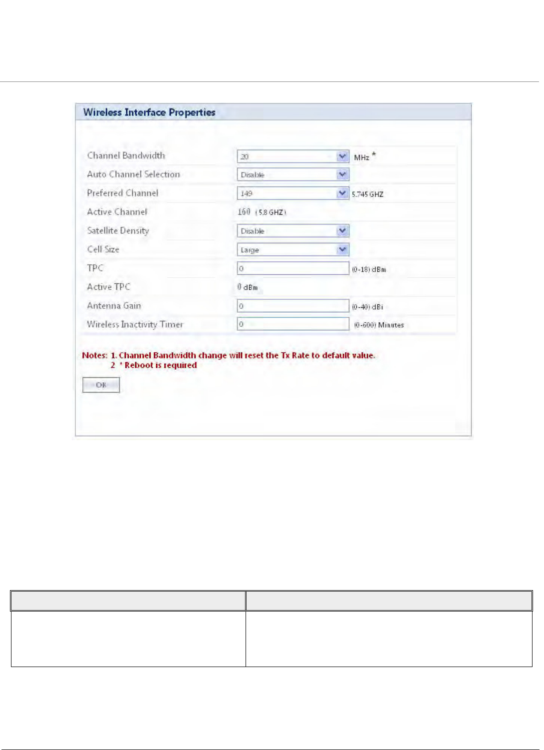
Advanced Configuration
Tsunami QB-8100 Series (100 Mbps/5 Mbps Models) Installation and Management Guide 52
Figure 4-7 Wireless interface properties
2. Enter the appropriate parameters. See the following table that lists the parameters and their descriptions.
3. Click OK.
NOTES:
•If World/Russia frequency domain is selected, establishing WORP link might take longer time because the End Point
B has to scan relatively more number of channels.
•When you modify wireless parameters and click COMMIT, it may result in brief interruption of service.
Parameter Descriptions
Channel Bandwidth This parameter specifies the channel bandwidth. By default, it is
set to 20 MHz. 40 MHz can be selected for higher throughputs
depending on the distance and signal quality. 5 and 10 MHz can
be selected for greater flexibility in spectrum selection.

Advanced Configuration
Tsunami QB-8100 Series (100 Mbps/5 Mbps Models) Installation and Management Guide 53
Auto Channel Selection (ACS) Enable or disable the Auto Channel Selection for wireless
interface. If ACS is enabled on the End Point A, it scans all the
channels and selects the best channel at the startup. If ACS is
enabled on the End Point B, End Point B continuously scans all
the channels till it connects to an End Point A.
By default, ACS is disabled on End Point A and enabled on End
Point B.
Preferred Channel Select a channel from the drop-down menu if you want to
operate the device in that specific channel.
NOTE: Preferred channel cannot be configured when
ACS is enabled. If DFS is active, the device will
automatically pick a new channel when radar
interference is detected.
Active Channel This displays the current operating channel on which wireless
interface is operating.
NOTE: Active Channel can be different from Preferred
Channel if radar interface is detected.
Parameter Descriptions

Advanced Configuration
Tsunami QB-8100 Series (100 Mbps/5 Mbps Models) Installation and Management Guide 54
Satellite Density Satellite Density setting helps achieve maximum bandwidth in a
wireless network. It influences the receive sensitivity of the radio
interface and improves operation in environments with high
noise level.
Reducing the sensitivity of the device enables unwanted “noise”
to be filtered out (it disappears under the threshold).
You can configure the Satellite Density to be Disable, Large,
Medium, Small, Mini, or Micro. By default, Satellite Density is
disabled. The Medium, Small, Mini, and Micro settings are
appropriate for high noise environments; whereas, Large is
appropriate for a low noise environment. A long distance link
may have difficulty maintaining a connection with a small
density setting because the wanted signal can disappear under
the threshold. Consider both noise level and distance between
the peers in a link when configuring this setting. The threshold
should be chosen higher than the noise level, but sufficiently
below the signal level. A safe value is 10dB below the present
signal strength.
If the Signal-to-Noise Ratio (SNR) is not sufficient, you may need
to set a lower data rate or use antennas with higher gain to
increase the margin between wanted and unwanted signals. In a
point-to-multipoint configuration, the End Point A should have a
density setting suitable for End Point B, especially the ones with
the lowest signal levels (longest links). Take care when
configuring a remote interface; check the available signal level
first, using Remote Link Test.
See Sensitivity Threshold Values for more information on
Sensitivity threshold values corresponding to various Satellite
Density values.
NOTE: When the remote interface is accidentally set to
small and communication is lost, it cannot be
reconfigured remotely and a local action is required
to bring the communication back. Therefore, the best
place to experiment with the level is at the device that
can be managed without going through the link. If
the link is lost, the setting can be adjusted to the
correct level to bring the link back.
Cell Size This parameter specifies the cell size for the TPC setting on the
wireless medium. By default, the cell size is configured to Large.
You can configure the cell size as Large, Medium or Small. The
TPC range is controlled by this parameter.
Parameter Descriptions

Advanced Configuration
Tsunami QB-8100 Series (100 Mbps/5 Mbps Models) Installation and Management Guide 55
TPC With Transmit Power Control (TPC), you can adjust the output
power of the device to a lower level. This is performed to reduce
interference with the neighboring devices. It can be helpful
when higher gain antenna is used without violating the
maximum radiated output power for a country or regulatory
domain. This value can be configured in 1 dB increments.
NOTES:
•This feature only lets you decrease the output
power; it does not let you increase the output power
beyond the maximum allowed defaults for the
selected frequency and country.
•The range of values depend on the Cell Size.
Active TPC If the feature Automatic Transmit Power Control (ATPC) is
enabled automatically, this field appears for United States 5 GHz
frequency domain only.
NOTE: This field is not displayed for United States 5.8
GHz frequency domain.
Antenna Gain The sensitivity of the radio card can be modified when detecting
radar signals in accordance with ETSI, FCC, and IC Dynamic
Frequency Selection (DFS) requirements. As the radar detection
threshold is fixed by ETSI, the FCC, and IC and a variety of
antennas with different gains may be attached to the device, you
must adjust this threshold to account for higher than expected
antenna gains. This can avoid false radar detection events which
can result in frequent change in the Frequency channels.
Configure the threshold for radar detection at the radio card to
compensate for increased external antenna gains. The Antenna
Gain value ranges from 0 to 40. The default value is 0.
NOTE: Modifying any of the wireless parameters results
in temporary loss of connectivity between the End
Point A and End Point B.
Wireless Inactivity Timer Resets the wireless interface if there is no change in the Tx and
Rx Packet Count in the specified interval of time. The default
value is set to 0 minutes (disabled) and can be configured
between 0 to 600 minutes.
Parameter Descriptions

Advanced Configuration
Tsunami QB-8100 Series (100 Mbps/5 Mbps Models) Installation and Management Guide 56
4.4.4 Blacklist Information
This section displays information regarding various blacklisted channels. It consists of the following parameters.
NOTE: Click COMMIT for the changes to take effect.
4.4.5 Sensitivity Threshold Values
Sensitivity threshold values corresponding to various Satellite Density values are given in the table below:
4.4.6 MIMO Properties
The MIMO Properties screen allows you to configure the Multiple-Input-Multiple-Output radio to achieve maximum
performance and high throughput.
To configure MIMO properties
1. Click ADVANCED CONFIGURATION > Wireless > Interface1 > MIMO Properties. The MIMO Properties screen
opens as shown below.
Parameter Description
Channel Number The channel number indicates the channel that is
blacklisted.
Reason The reason for which that particular channel is
blacklisted. The most common reason for blacklisting a
channel is the presence of a radar in that channel.
Time Elapsed The time elapsed since the channel was blacklisted.
When the channel is black listed due to the presence of
a radar, it will be de-blacklisted after 30min.
Satellite Density Receive Sensitivity Threshold Defer Threshold
Large -96 dbm -62 dbm
Medium -86 dbm -62 dbm
Small -78 dbm -52 dbm
Mini -70 dbm -42 dbm
Micro -62 dbm -36 dbm
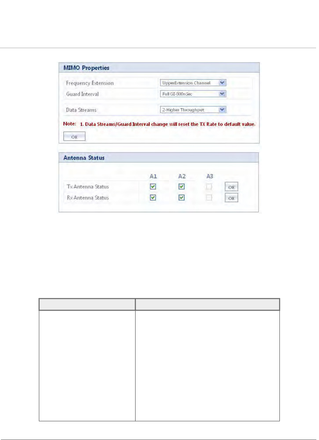
Advanced Configuration
Tsunami QB-8100 Series (100 Mbps/5 Mbps Models) Installation and Management Guide 57
Figure 4-8 MIMO Properties
2. Enter the appropriate parameters on the MIMO Properties screen. See the following table that lists the parameters and
their descriptions.
3. Click OK.
NOTE: When you modify MIMO parameters and click COMMIT, it may result in brief interruption of service.
Parameter Description
Frequency Extension Configuration of this parameter is valid only if the
channel bandwidth is 40 MHz. If Upper Extension
Channel is selected, the radio automatically uses the
current channel (20MHz) as well as next upper
adjacent channel (20 MHz) for data transmission. If
Lower extension channel is selected, the radio
automatically uses the current channel (20MHz) as well
as lower adjacent channel (20 MHz) for data
transmission.
For example, if channel 36 is selected in 40 + mode,
the radio uses 36 as well as next upper adjacent
channel 40 also for data transmission, similarly if
channel 40 is used in 40- mode, the radio uses 40 as
well as the next lower adjacent channel 36 for data
transmission.

Advanced Configuration
Tsunami QB-8100 Series (100 Mbps/5 Mbps Models) Installation and Management Guide 58
Modifying the Guard Interval, Data Streams, Tx Antenna Status and Rx Antenna Status will reset the Tx Rate to default.
4.4.7 DFS
Dynamic Frequency Selection is a mechanism to allow unlicensed devices to share spectrum with existing radar systems.
The operation of a system with DFS capability takes place in the following sequence:
1. The master device that can initiate communication selects a channel and monitors that channel for potential radar
signal for a minimum listening time (channel availability check time). No transmissions can occur during this period.
2. If the radar is detected, then the system has to go and select another channel and repeat the channel availability check
on the new channel (the original channel is added to a list of channels with radar).
3. Once the channel has been scanned for radar and found clean, the device starts using that channel.
4. While using the channel, the network’s master device continuously monitors for potential interference from a radar
source (this is referred to as in-service monitoring). If the radar is detected, then the network’s master device stops
transmitting in that channel. The channel is added to the list of channels with radar.
5. The master device then selects a new channel (channel that is not on the radar list).
6. A channel on the radar list can be purged once the Non Occupancy Period (NOP) has elapsed for that channel.
NOTE: For Europe 5.8 GHz channel, once End Point A / End Point B finds a clean channel (after 60 sec radar scan), it
does not need to perform any 60 seconds scan again for RADAR for next 24 hours. This is not applicable when device
is rebooted or that particular channel got blacklisted earlier.
4.4.7.1 DFS in End Point A Mode
Dynamic Frequency Selection (DFS) is enabled automatically based on the selected frequency domain. The device selects a
channel to operate as follows:
Guard Interval Possible values for Guard interval are 800 nSec and
400 nSec. 400 nSec is valid only for 40 MHz channel
bandwidth.
Data Streams MIMO radio uses multiple antennas for transmitting
and receiving the data. These data streams specify the
number of data streams over the air transmitted or
received in parallel.
•Data streams “1-Longer Range” uses a single
flow of the signals on the antennas.
•Data streams “2-Higher Throughput” uses
double flow of the signals on the antennas in
parallel.
Tx Antenna Status This parameter allows the user to specify the antenna
to be used for data transmission. Selecting the
respective antenna number checkbox specifies radio to
use that specific antenna for data transmission.
Rx Antennas Status This parameter allows the user to specify the antenna
to be used for data reception. Selecting the respective
antenna number checkbox specifies radio to use that
specific antenna for data reception.
Parameter Description
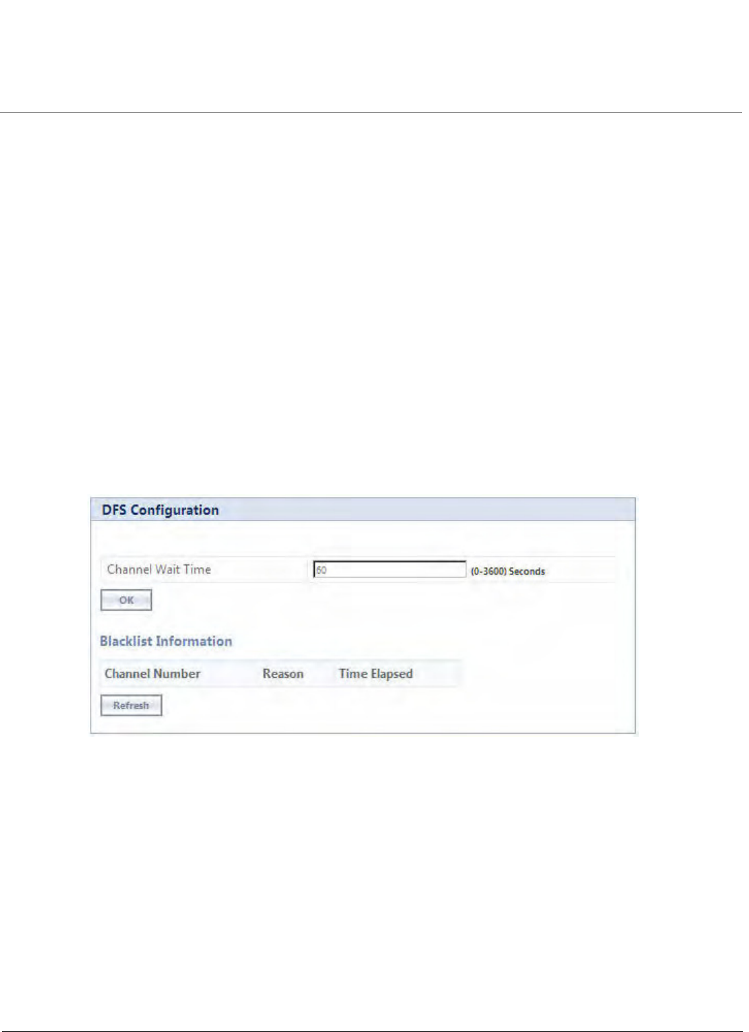
Advanced Configuration
Tsunami QB-8100 Series (100 Mbps/5 Mbps Models) Installation and Management Guide 59
If ACS is disabled, during initialization, the device selects the Preferred Channel to be the operational channel. If ACS is
enabled, during initialization, the device scans all the channels in the configured frequency domain and selects the channel
with the best RSSI to be the operational channel.
Once the operating channel is selected, the device scans the channel for radar presence for a duration of Channel Wait Time.
If no radar is detected, the device starts operating in that channel. If radar is detected, the channel is blacklisted for 30
minutes and a different channel is selected. To select the next operational channel, the device scans all non-blacklisted
channels and selects the channel with best RSSI.
At any point of time, if Radar is detected on the current operating channel, the device blacklists that channel and scans all
non-blacklisted channels and selects the channel with best RSSI.
NOTE: Scanning is performed only on the frequencies allowed in the regulatory domain of the frequency/band
selected when it is required for radar detection and avoidance.
DFS Configuration in End Point A Mode
To co n figure DFS in End Point A mode,
1. Click ADVANCED CONFIGURATION> Wireless > Interface 1 > DFS. The DFS Configuration screen appears as
shown below.
2. Select the appropriate parameters. See the DFS Configuration table that lists the parameters and their descriptions.
3. Click OK.
Figure 4-9 DFS Configuration in End Point A Mode
4.4.7.2 DFS in End Point B Mode
1. When not connected to the End Point A, the End Point B scans continuously for all the channels in the configured
Frequency Domain for the presence of End Point A. If suitable End Point A is found in a channel, the End Point B tries
to connect to it.
NOTE: Since the device may need to scan for radar on multiple channels, you must allow a sufficient amount of time
for the units to start up. This is considerably longer than when the device is not using DFS. This is expected behavior.
The Startup time is within four minutes if no radar is detected, but up to one minute is added for every selected
channel that results in radar interference.
2. After selecting the best channel from its End Point A -scan list, the End Point B scans for the radar during Channel
Wait Time in that channel. The default Channel Wait Time value is 60 seconds. It starts transmitting only when the
channel is found clean during this scan time.
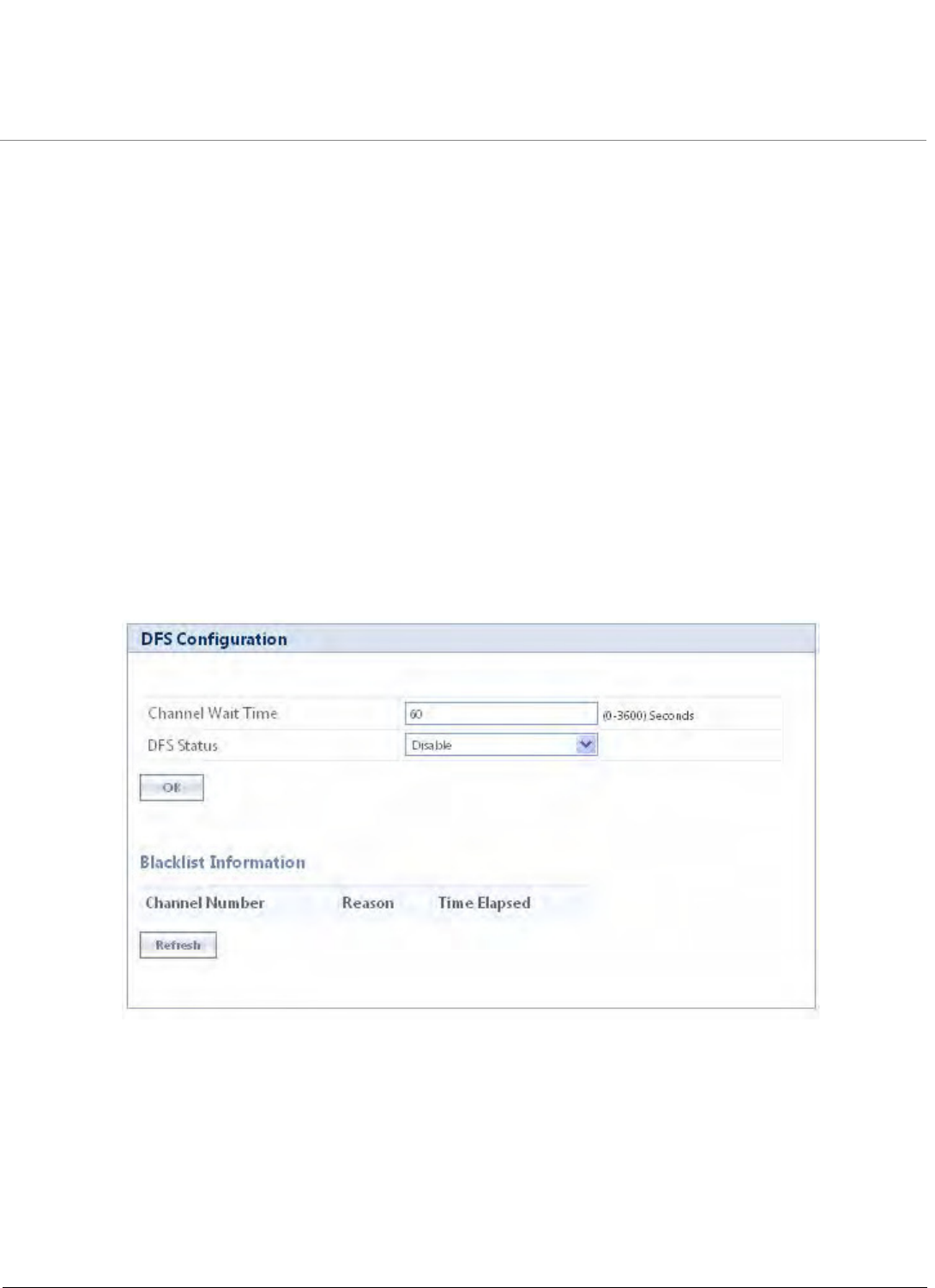
Advanced Configuration
Tsunami QB-8100 Series (100 Mbps/5 Mbps Models) Installation and Management Guide 60
3. During its operation, the End Point B scans for radar continuously and after detecting the radar, it sends a message to
the End Point A indicating radar detection on that current channel and blacklists that channel for Non Occupancy
Period (NOP). The default NOP is 30 minutes.
4. End Point B restarts scanning for the End Point A as mentioned above in Step 1.
5. End Point B never scans any blacklisted channels.
6. End Point B de-blacklists the blacklisted channel only after Non Occupancy Period.
For detailed information on DFS enabled countries, refer to Frequency Domains and Channels.
End Point A’s behavior on receiving RADAR event message from End Point B
As soon as End Point A receives RADAR event message from End Point B, End Point A de-registers that End Point B
immediately and blacklists that channel for NOP and triggers the channel switch in case of Point-To-Point link.
In case of Point-To-MultiPoint also, End Point A shall de-register the End Point B, if it receives RADAR event message from End
Point B.
DFS Configuration in End Point B Mode
To co n figure DFS in End Point B mode,
1. Click ADVANCED CONFIGURATION > Wireless > Interface 1 > DFS. The DFS Configuration screen appears as
shown below:
Figure 4-10 DFS Configuration in End Point B Mode
The DFS Configuration table holds the DFS parameter configurations.
2. Select the appropriate parameters.
3. Click OK.

Advanced Configuration
Tsunami QB-8100 Series (100 Mbps/5 Mbps Models) Installation and Management Guide 61
See the following DFS parameter configurations table that lists the parameters and their descriptions
4.4.7.3 Blacklist Information
This section displays information regarding various blacklisted channels. It consists of the following parameters.
NOTE: Click COMMIT for the changes to take effect.
4.4.8 DDRS
Dynamic Data Rate Selection (DDRS) feature allows the End Point A or End Point B to monitor the remote average
signal-to-noise ratio (SNR) and the number of retransmissions between the End Point A and End Point B or vice versa. End
Point A or End Point B adjusts the transmission data rate to an optimal value to provide the best possible throughput
according to the current communication conditions and link quality.
End Point A or End Point B runs the DDRS Algorithm separately based on their local DDRS Status configuration. When DDRS
Status is enabled on End Point A, End Point A monitors the remote SNR and number of retransmission for every registered
End Point B and it can adjust different transmission rate for different End Point Bs based on their link condition. When DDRS
Status is enabled on End Point B, End Point B monitors the remote SNR and number of retransmissions for End Point A and
can adjust the transmission rate according to the link condition.
Note that DDRS can be enabled or disabled both on End Point A and End Point B separately.
Parameter Description
Channel Wait Time End Point B after selecting the best channel from its
End Point A-scan list, scans for the RADAR for a period
of 60 seconds in that particular channel. This Channel
Wait Time ranges from 0 to 3600 sec. By default,
Channel Wait Time is set to 60 sec.
NOTE: End Point B starts transmitting only when
the channel is found clean during the
channel wait time (60 seconds scan) for
RADAR.
DFS Status (End Point B only) This parameter is displayed in End Point B only. Select
the DFS Status “Enable” or “Disable” from the
drop-down box provided. By default, DFS Status is
Disable.
Parameter Description
Channel Number The channel number indicates the channel that is
blacklisted.
Reason The reason for which that particular channel is
blacklisted. The most common reason for blacklisting a
channel is the presence of a local radar or remote radar
in that channel.
Time Elapsed The time elapsed since the channel was blacklisted.
When the channel is black listed due to the presence of
a radar, it will be de-blacklisted after 30min.
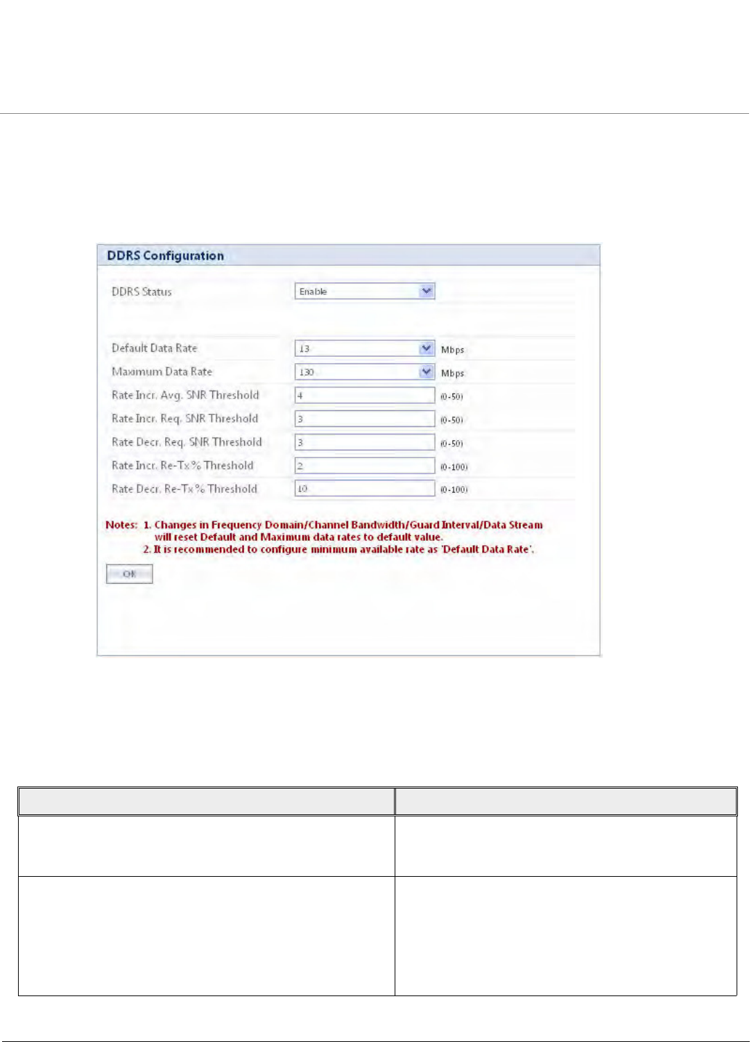
Advanced Configuration
Tsunami QB-8100 Series (100 Mbps/5 Mbps Models) Installation and Management Guide 62
4.4.8.1 DDRS Configuration
To co n figure DDRS,
1. Click ADVANCED CONFIGURATION > Wireless > Interface 1 > DDRS. The DDRS Configuration screen appears as
shown below:
Figure 4-11 DDRS Configuration
The DDRS Configuration table holds the DDRS parameter configurations.
2. Select the appropriate parameters. See the following table that lists the parameters and their descriptions.
3. Click OK.
Parameter Description
DDRS Status Select the DDRS Status Enable or Disable from the
drop-down box provided to activate or deactivate
DDRS feature. By default, DDRS Status is Disabled.
DDRS Default Data Rate This parameter specifies the lowest data rate that is
selected during DDRS Algorithm. By default, 13Mbps
is selected.
NOTE: Algorithm will select the transmission
rate between DDRS Default Data Rate
and DDRS Max Data Rate configuration.

Advanced Configuration
Tsunami QB-8100 Series (100 Mbps/5 Mbps Models) Installation and Management Guide 63
DDRS Max Data Rate This parameter specifies the maximum data rate that is
selected during DDRS Algorithm. By default, 130Mbps
is selected.
NOTE: Algorithm will select the transmission
rate between DDRS Default Data Rate
and DDRS Max Data Rate configuration.
Rate Incr. Avg. SNR Threshold This parameter specifies a threshold value, which is
added to the average remote SNR and this summation
is compared with the current remote SNR. If the
current remote SNR is greater than this summation,
then the same rate is maintained. If the current remote
SNR is smaller than or equal to this summation, then
new rate is selected. By default, 4dB is configured.
Rate Incr. Req. SNR Threshold This parameter specifies the threshold value, that is
added to the minimum required SNR threshold of next
higher data rate and this summation is compared with
average remote SNR. If the average remote SNR is
greater than or equal to the summation, then new
data rate is selected. By default, 3dB is configured.
NOTE: Refer to Table 4-1 and 4-2 for Minimum
Required SNR for different data rates.
These values are NOT user configurable.
Rate Decr. Req. SNR Threshold This parameter specifies the threshold value, that is
added to the minimum required SNR threshold of
current data rate and this summation is compared with
average remote SNR. If the average remote SNR is
lower than the summation, then next lower data rate is
selected. By default, 3dB is configured.
NOTE: Refer to Table 4-1 and 4-2 for Minimum
Required SNR for different data rates.
These values are NOT user configurable.
Rate Incr. Re-Tx% Threshold This parameter specifies the percentage of
re-transmission for last 128 transmissions. If the
re-transmission percentage for last 128 transmissions is
greater than Rate Incr. Re-Tx% Threshold value, then
the current transmission rate is maintained. By default
2% is configured.
Rate Decr. Re-Tx% Threshold This parameter specifies the percentage of
re-transmission for last 128 transmissions. If the
re-transmission percentage for last 128 transmission is
greater than Rate Decr. Re-Tx% Threshold value, then
the next lower transmission rate is selected. By default
10% is configured.
Parameter Description

Advanced Configuration
Tsunami QB-8100 Series (100 Mbps/5 Mbps Models) Installation and Management Guide 64
Table 4-1 Data Rates to Rate Index Mapping Table
Table 4-2 DDRS Minimum Required SNR Table
When DDRS Status is enabled, the DDRS Status field is displayed and WORP Tx Rate is disabled in BASIC
CONFIGURATION Screen. See Basic Configuration Information for more details. Also when enabled, the DDRS Status field
is displayed and WORP Tx Rate is also disabled in ADVANCED CONFIGURATION > Wireless > Interface 1 > WORP
screen. See Configuring WORP Properties in End Point A Mode for more information.
Rate
Index
Data Rates (Mbps)
5 MHz Channel
Bandwidth (for
Full GI-800ns)
10 MHz Channel
Bandwidth (for
Full GI-800ns)
20 MHz Channel
Bandwidth (for
Full GI-800ns)
40 MHz Channel Bandwidth
Longer
Range
Higher
Through
put
Longer
Range
Higher
Through
put
Longer
Range
Higher
Through
put
Short GI-400ns Full GI-800ns
Longer
Range
Higher
Through
put
Longer
Range
Higher
Though
put
1 1.6 3.3 3.3 6.5 6.5 13 15 30 13.5 27
2 3.3 6.5 6.5 13 13 26 30 60 27 54
3 4.9 9.7 9.7 19.5 19.5 39 45 90 40.5 81
4 6.5 13 13 26 26 52 60 120 54 108
5 9.7 19.5 19.5 39 39 78 90 180 81 162
61326265252104120240108216
7 14.6 29.3 29.3 58.5 58.5 117 135 270 121.5 243
8 16.2 32.5 32.5 65 65 130 150 300 135 270
Rate Index Legacy Mode Enabled
Minimum Required SNR (dB)
Single Stream Dual Stream
17 9
210 13
313 16
416 19
520 25
625 28
728 31
831 34
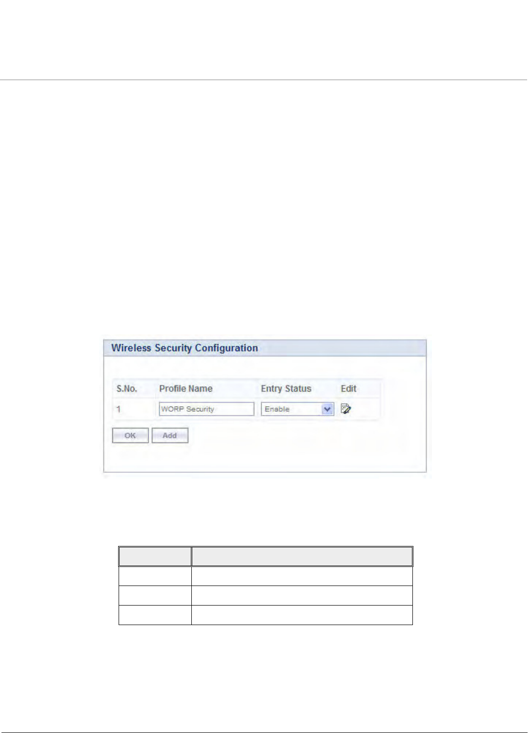
Advanced Configuration
Tsunami QB-8100 Series (100 Mbps/5 Mbps Models) Installation and Management Guide 65
4.5 Security Configuration
4.5.1 Setting Up Wireless Security
In Wireless Security page, you can configure security mechanisms used to secure the communication link between End Point
A and End Point B. By default, a security profile (WORP Security) is preconfigured with the default configuration for WORP
security. However, more profiles can be created as required. Even though multiple security profiles can be created, only one
security profile can be active at a time. The active security profile is configured as part of the WORP property Security Profile
Name. For a security profile to be active, it must be enabled. Refer to Configuring WORP Properties in End Point A Mode
for details.
NOTES:
•The active security profile parameters on the End Point A and End Point B should match for the connection to work
as desired.
• A maximum of eight security profiles can be created.
To configure the Wireless security properties
1. Click ADVANCED CONFIGURATION > Security > Wireless Security. The Wireless Security Configuration screen is
displayed as shown below.
Figure 4-12 Wireless Security Configuration
2. Select the appropriate parameters. See the following table that lists the parameters and their descriptions.
3. Click OK.
NOTES:
•By default, WORP Security is added to the wireless security configuration.
•Default authentication mode is WORP.
Field Description
Profile Name Specifies the security profile name.
Entry status Used to enable or disable the security profile.
Edit Click Edit to modify the Profile parameters.
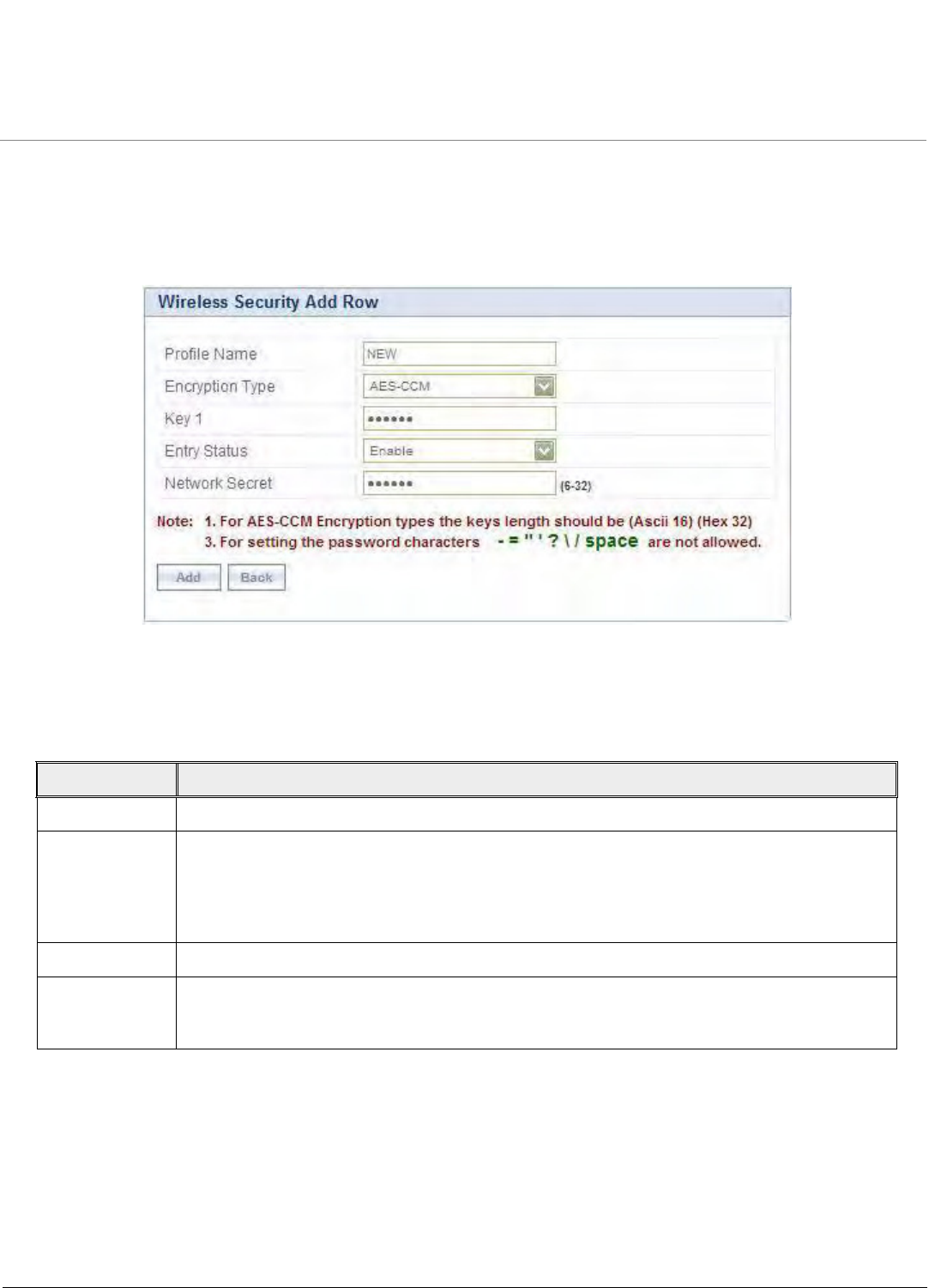
Advanced Configuration
Tsunami QB-8100 Series (100 Mbps/5 Mbps Models) Installation and Management Guide 66
4.5.1.1 Creating a New Security Profile
To create a new security profile
1. Click ADVANCED CONFIGURATION > Security > Wireless Security.
2. Click Add in the Wireless Security Configuration screen to create a new entry. The Wireless Security Add Row screen is
displayed as shown below.
Figure 4-13 Creating a New Security Profile
3. Enter the appropriate parameters in the Wireless Security Add Row screen. See the following table for information on
the parameters and their descriptions.
4. Click Add.
Field Description
Profile Name Enter the security profile name.
Encryption Type Select an option from None or AES-CCM for the Encryption Type.
1. None - If this option is selected, no encryption will be applied to the wireless link frames.
2. AES-CCM - This option represents CCM Protocol with AES Cipher restricted to 128 bits.
•Key 1 : Enter 16 ASCII Characters or 32 Hex Digits.
Entry status Select Enable/Disable to enable or disable the status of the security profile.
Network Secret Enter the WORP Protocol Secret Key used for authenticating the End Point B with End Point A.
NOTE: End Point A and End Point B must have same Network Secret.

Advanced Configuration
Tsunami QB-8100 Series (100 Mbps/5 Mbps Models) Installation and Management Guide 67
Sample Security Profile Configuration
End Point A End Point B
Profile Name NEW NEW
Encryption Type AES-CCM AES-CCM
Key 1 1234567890abcdef1234567890abcdef
(32 Hexadecimal digits)
or
publicpublic1234
(16 ASCII Characters)
1234567890abcdef1234567890abcdef
(32 Hexadecimal digits)
or
publicpublic1234
(16 ASCII Characters)
Network Secret public public
Entry status Enable Enable
NOTE:
•By using the preceding security configuration, Wireless link data follows these constraints:
–At End Point A, frames going out from End Point A are encrypted using Key 1 and
decrypted using Key 2.
–At End Point B, frames going out from End Point B are encrypted using Key 2 and
decrypted using Key 1.
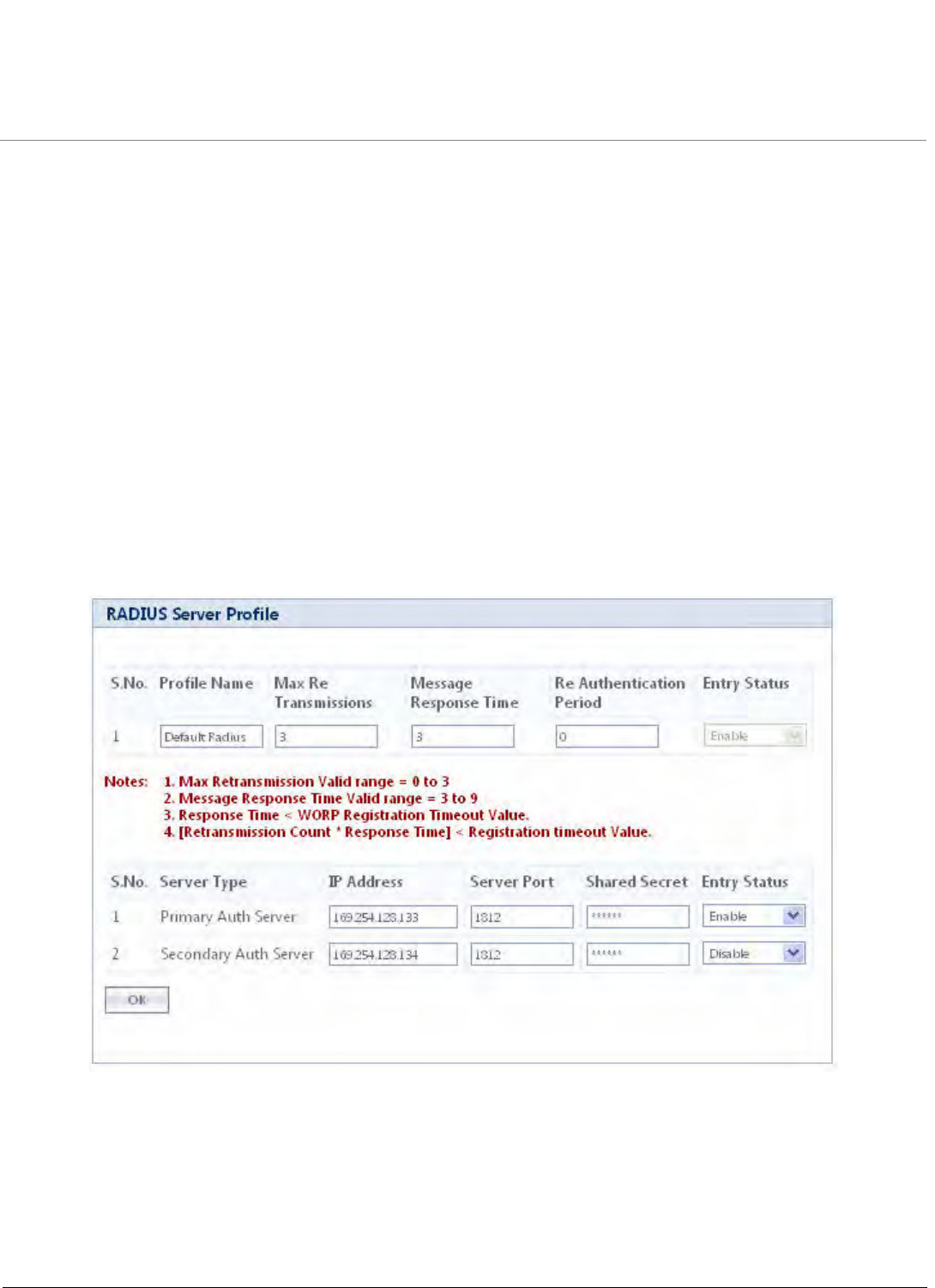
Advanced Configuration
Tsunami QB-8100 Series (100 Mbps/5 Mbps Models) Installation and Management Guide 68
4.5.1.2 Modifying a Security Profile
To edit the parameters of the existing security profiles
1. Click ADVANCED CONFIGURATION > Security > Wireless Security.
2. Click Edit. The Wireless Security Edit Row page appears.
3. Edit the parameters and click OK.
4. To apply the configured properties to the device, click COMMIT.
4.5.2 Configuring the Radius Server Profile (End Point A Only)
In large networks, you can maintain a list of MAC addresses on a centralized location using a RADIUS authentication server
that grants or denies access.
A RADIUS server profile consists of a Primary and a Secondary RADIUS server that can be assigned to act as MAC
Authentication servers. Configuration of Secondary Authentication Server is optional. The Radius server is referred to only
when it is enabled on the WORP Configuration page.
To configure the Radius Server profile
1. Click ADVANCED CONFIGURATION > Security > RADIUS. The Radius Server Profile screen is displayed as shown
below.
Figure 4-14 RADIUS Server Profile
2. Enter the appropriate parameters on the Radius Server Profile screen. See the following table that lists the parameters
and their descriptions.
3. Click OK.

Advanced Configuration
Tsunami QB-8100 Series (100 Mbps/5 Mbps Models) Installation and Management Guide 69
Following constraints apply for Radius Profile configuration:
1. Message Response Time should always be less than WORP Registration Timeout parameter value.
2. If Max Retransmissions is configured as Zero, retransmissions do not occur.
3. The value of Max Retransmissions multiplied by Message Response Time should be less than WORP
Registration Timeout value.
4. Max Retransmission Valid Range is 0 to 3.
5. Message Response Time Valid Range is 3 to 9.
NOTE: RADIUS authentication configuration is applicable only for End Point A.
4.5.3 Configuring the MAC ACL (End Point A Only)
You can control the access to the network using MAC Access Control List (ACL). MAC ACL is available only on End Point A.
MAC Authentication is supported on the wireless interface only (not supported for the devices on the Ethernet side) and only
End Point B wireless MAC addresses should be added to the list. The MAC ACL is referred to only when it is enabled on the
WORP Configuration page.
To configure the MAC ACL
1. Click ADVANCED CONFIGURATION > Security > MAC ACL. The MAC Access Control screen is displayed as shown
below.
Parameter Description
Profile Name Specifies the profile name.
Max Retransmissions Specifies the maximum retransmissions allowed.
Message Response Time Specifies the message response time.
Re Authentication Period Specifies the Re Authentication Period.
Entry status Displays the Radius profile as Enable.
Server Type This is a read only parameter and displays the server type. Two
Server Types are supported: Primary Auth Server and
Secondary Auth Server.
IP Address Enter the Server’s IP address.
Server Port Specifies the port number which is used by the unit and the Radius
server to communicate. By default, RADIUS Authentication
Server communicates on port 1812.
Shared Secret Specifies the password shared by the RADIUS server and the
QB-8100 device. The default password is public.
Entry Status Select Enable/Disable to enable or disable the RADIUS server
status.
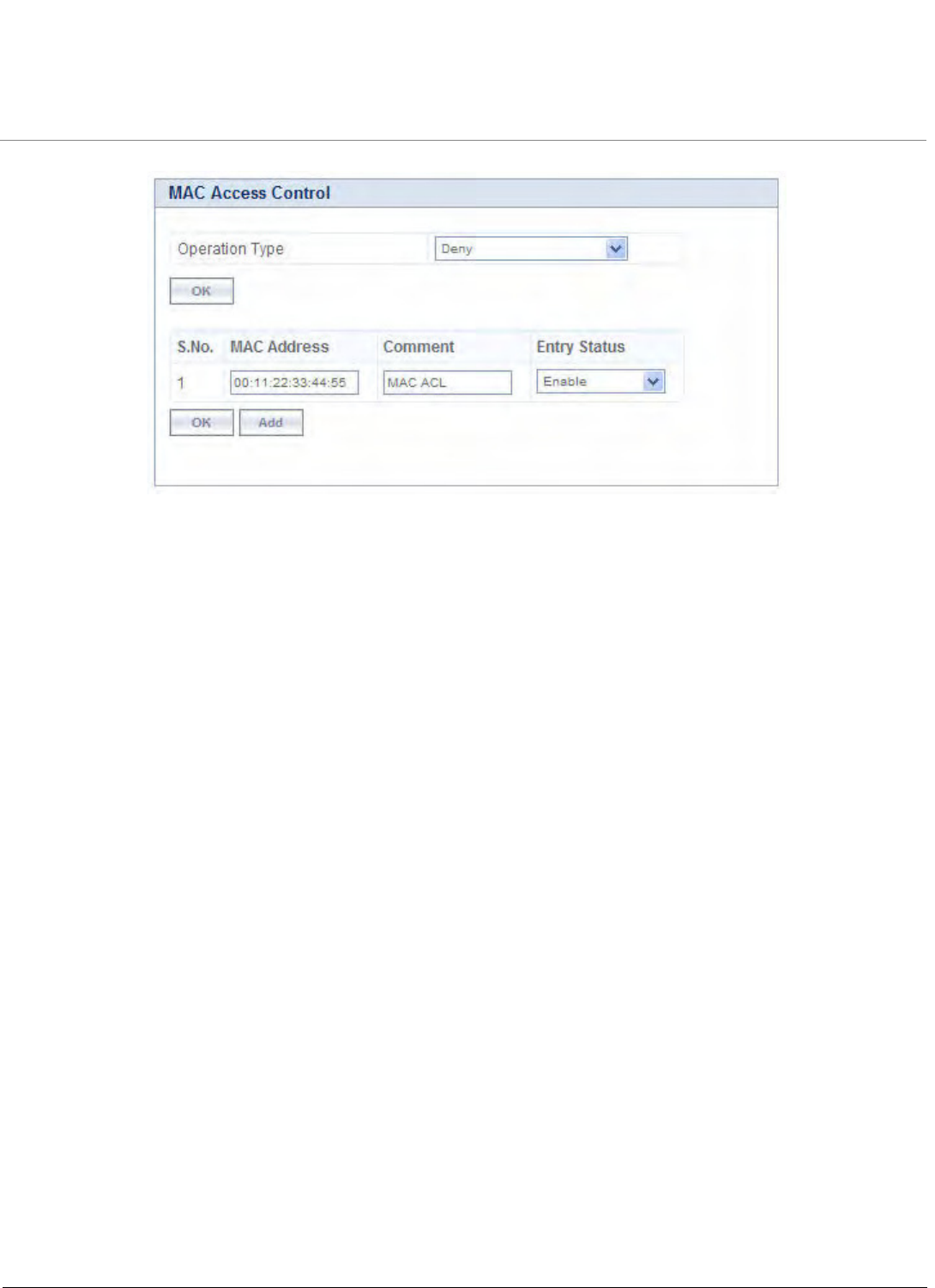
Advanced Configuration
Tsunami QB-8100 Series (100 Mbps/5 Mbps Models) Installation and Management Guide 70
Figure 4-15 MAC Access Control
2. Select the Operation Type as either Allow or Deny.
NOTE: Based on the Operation Type, the user can allow or deny the association of the MAC ACL profile to an End
Point B.
3. Click OK.
To add entries to MAC Access Control table
1. Click Add in the MAC Access Control screen. The MAC ACL Add Row page appears.
2. Enter the MAC Address and Comment, and then select Enable/Disable to enable or disable Entry Status of the
MAC Address.
3. Click Add.
NOTE:
• MAC Access Control authentication is available only for End Point A.
•The maximum number of MAC addresses that can be added to this table is 250.
•MAC ACL Status and Radius MAC ACL Status fields cannot be enabled simultaneously.

Advanced Configuration
Tsunami QB-8100 Series (100 Mbps/5 Mbps Models) Installation and Management Guide 71
4.6 Quality of Service (QoS) Configuration
The Quality of Service (QoS) feature is based on the 802.16 standard and defines the classes, service flows, and packet
identification rules for specific types of traffic.
4.6.1 QoS Concepts and Definitions
The software supports QoS provisioning from the End Point A only. You may define different classes of service on a End Point
A that can then be assigned to the End Point B that is associated, or that may get associated, with that End Point A.
You can create, edit, and delete classes of service that are specified by the following hierarchy of parameters:
•Packet Identification Rule (PIR) – up to 64 rules, including 18 predefined rules
•Service Flow class (SFC) – up to 32 SFCs, including 8 predefined SFCs; up to 8 PIRs may be associated per SFC
•Priority for each rule within each SF class – 0 to 255, with 0 being lowest priority
•QoS class – up to 8 QoS classes, including 5 predefined classes; up to 8 SFCs may be associated per QoS class
4.6.1.1 Packet Identification Rule (PIR)
A Packet Identification Rule is a combination of parameters that specifies what type of traffic is allowed or disallowed. You
can create up to 64 different PIRs, including 18 predefined PIRs. Also, you can create, edit, and delete PIRs that contain none,
one, or more of the following classification fields:
•Rule Name
•IP ToS (Layer 3 QoS identification)
•802.1p tag (layer 2 QoS identification)
•IP Protocol List containing up to 4 IP protocols
•VLAN ID
•PPPoE Encapsulation
•Ether Type (Ethernet Protocol identification)
•Up to 4 TCP/UDP Source port ranges
•Up to 4 TCP/UDP Destination port ranges
•Up to 4 pairs of Source IP address + Mask
•Up to 4 pairs of Destination IP address + Mask
•Up to 4 source MAC addresses + Mask
•Up to 4 destination MAC addresses + Mask
NOTE: IP Address, TCP/UDP Port, MAC Address need to be configured separately and associate those classification in
PIR details if required.
A good example is provided by the 18 predefined PIRs. Note that these rules help identify specific traffic types:
1. All – No classification fields, all traffic matches
2. L2 Multicast
a. Ethernet Destination (dest = 0x010000000000, mask = 0x010000000000)
3. L2 Broadcast
a. Ethernet Destination (dest = 0xffffffffffff, mask = 0xffffffffffff)
4. Cisco VoIP UL
a. TCP/UDP Source Port Range (16,000-33,000)
b. IP Protocol List (17 = UDP)
5. Vonage VoIP UL

Advanced Configuration
Tsunami QB-8100 Series (100 Mbps/5 Mbps Models) Installation and Management Guide 72
a. TCP/UDP Source Port Range (5060-5061, 10000-20000)
b. IP Protocol List (17 = UDP)
6. Cisco VoIP DL
a. TCP/UDP Destination Port Range (16,000-33,000)
b. IP Protocol List (17 = UDP)
7. Vonage VoIP DL
a. TCP/UDP Destination Port Range (5060-5061, 10000-20000)
b. IP Protocol List (17 = UDP)
8. TCP
a. IP Protocol List (6)
9. UDP
a. IP Protocol List (17)
10. PPPoE Control
a. Ether Type Rule (Ether Type = DIX-Snap, Ether Value = 0x8863)
11. PPPoE Data
a. Ether Type Rule (Ether Type = DIX-Snap, Ether Value = 0x8864)
12. IP
a. Ether Type Rule (Ether Type = DIX-Snap, Ether Value = 0x0800)
13. ARP
a. Ether Type Rule (Ether Type = DIX-Snap, Ether Value = 0x0806)
14. Expedited Forwarding
a. IP TOS/DSCP (ToS low=45(0x2D), ToS high=45(0x2D), ToS mask = 63(0x3F))
15. Streaming Video (IP/TV)
a. IP TOS/DSCP (ToS low=13(0x0D), ToS high=13(0x0D), ToS mask = 63(0x3F))
16. 802.1p BE
a. Ethernet Priority (low=0, high=0) (this is the equivalent of the User Priority value in the TCI (Tag Control
Information) field of a VLAN tag)
17. 802.1p Voice
a. Ethernet Priority (ToS low=6, ToS high=6) (this is the equivalent of the User Priority value in the TCI (Tag Control
Information) field of a VLAN tag)
18. 802.1p Video
a. Ethernet Priority (ToS low=5, ToS high=5) (this is the equivalent of the User Priority value in the TCI (Tag Control
Information) field of a VLAN tag)
NOTE: Two different VoIP rule names have been defined for each direction of traffic, Uplink (UL) and Downlink (DL),
(index numbers 4 to 7). This has been done to distinguish the proprietary nature of the Cisco VoIP implementation as
opposed to the more standard Session Initiation Protocol (SIP) signaling found, for example, in the Vonage-type VoIP
service.
4.6.1.2 Service Flow Class (SFC)
A Service Flow class defines a set of parameters that determines how a stream of application data that matches a certain
classification profile will be handled. You can create up to 32 different SFCs, including 8 predefined SFCs. Also, you can
create, edit, and delete SFCs that contain the following parameters and values:
•Service flow name
•Scheduling type – Best Effort (BE); Real-Time Polling Service (RTPS)

Advanced Configuration
Tsunami QB-8100 Series (100 Mbps/5 Mbps Models) Installation and Management Guide 73
•Service Flow Direction – Downlink (DL: traffic from End Point A to End Point B); Uplink (UL: traffic from End Point B to
End Point A)
•Maximum sustained data rate (or Maximum Information Rate, MIR) – specified in units of 1 Kbps from 8 Kbps up to
the maximum rate specified in the license.
•Minimum reserved traffic rate (or Committed Information Rate, CIR) – specified in units of 1 Kbps from 0 Kbps up to
the maximum rate specified in the license.
•Maximum Latency – specified in increments of 5 ms steps from a minimum of 5 ms up to a maximum of 100 ms
•Tolerable Jitter – specified in increments of 5 ms steps from a minimum of 0 ms up to the Maximum Latency (in ms)
•Traffic priority – zero (0) to seven (7), 0 being the lowest, 7 being the highest
•Maximum number of data messages in a burst – one (1) to sixteen (16), which affects the percentage of the maximum
throughput of the system
•Entry Status – Enable, Disable, and Delete
NOTE: Note that traffic priority refers to the prioritization of this specific Service Flow.
The device tries to deliver the packets within the specified latency and jitter requirements, relative to the moment of receiving
the packets in the unit. For delay-sensitive traffic, the jitter must be equal to or less than the latency. A packet is buffered until
an interval of time equal to the difference between Latency and Jitter (Latency – Jitter) has elapsed. The device will attempt to
deliver the packet within a time window starting at (Latency – Jitter) until the maximum Latency time is reached. If the SFC’s
scheduling type is real-time polling (RTPS), and the packet is not delivered by that time, it will be discarded. This can lead to
loss of packets without reaching the maximum throughput of the wireless link. For example, when the packets arrive in bursts
on the Ethernet interface and the wireless interface is momentarily maxed out, then the packets at the “end” of the burst
may be timed out before they can be sent.
Users can set up their own traffic characteristics (MIR, CIR, latency, jitter, etc.) per service flow class to meet their unique
requirements. A good example is provided by the 8 predefined SFCs:
1. UL-Unlimited BE
a. Scheduling Type = Best Effort
b. Service Flow Direction = Uplink
c. Entry Status = Enable
d. Maximum Sustained Data Rate = 102400 Mbps e. Traffic Priority = 0
2. DL-Unlimited BE (same as UL-Unlimited BE, except Service Flow Direction = Downlink)
3. DL-L2 Broadcast BE (same as UL-Unlimited BE, except Service Flow Direction = Downlink)
4. UL-G711 20 ms VoIP RTPS
a. Schedule type = RTPS (Real time Polling Service)
b. Service Flow Direction = Uplink
c. Entry Status = Enable
d. Maximum Sustained Data Rate = 88 Kbps
e. Minimum Reserved Traffic Rate = 88 Kbps
f. Maximum Latency = 20 milliseconds g. Traffic Priority = 1
5. DL-G711 20 ms VoIP rtPS (same as UL-G711 20ms VoIP rtPS, except Service Flow Direction = Downlink)
6. UL-G729 20 ms VoIP rtPS (same as UL-G711 20ms VoIP rtPS, except Maximum Sustained Data Rate and Maximum
Reserved Traffic Rate = 64 Kbps)
7. DL-G729 20 ms VoIP rtPS (same as UL-G729 20ms VoIP rtPS, except Service Flow Direction = Downlink)
8. DL-2Mbps Video
a. Schedule type = Real time Polling
b. Service Flow Direction = Downlink

Advanced Configuration
Tsunami QB-8100 Series (100 Mbps/5 Mbps Models) Installation and Management Guide 74
c. Initialization State = Active
d. Maximum Sustained Data Rate = 2 Mbps
e. Minimum Reserved Traffic Rate = 2 Mbps
f. Maximum Latency = 20 milliseconds
g. Traffic Priority = 1
Note that two different VoIP Service Flow classes for each direction of traffic have been defined (index numbers 4 to 7) which
follow the ITU-T standard nomenclatures: G.711 refers to a type of audio companding and encoding that produces a 64 Kbps
bitstream, suitable for all types of audio signals. G.729 is appropriate for voice and VoIP applications, but cannot transport
music or fax tones reliably. This type of companding and encoding produces a bitstream between 6.4 and 11.8 Kbps (typically
8 Kbps) according to the quality of voice transport that is desired.
4.6.1.3 QoS Class
A QoS class is defined by a set of parameters that includes the PIRs and SFCs that were previously configured. You can create
up to eight different QoS classes, including five predefined QoS classes. Up to eight SF classes can be associated to each QoS
class, and up to eight PIRs can be associated to each SF class. For example, a QoS class called “G711 VoIP” may include the
following SFCs: “UL-G711 20 ms VoIP rtPS” and “DL-G711 20 ms VoIP rtPS”.
In turn, the SFC named “UL-G711 20 ms VoIP rtPS” may include the following rules: “Cisco VoIP UL” and “Vonage VoIP UL”.
You can create, edit, and delete QoS classes that contain the following parameters:
•QoS class name
•Service Flow (SF) class name list per QoS class (up to eight SF classes can be associated to each QoS class)
•Packet Identification Rule (PIR) list per SF class (up to eight PIRs can be associated to each SF class)
•Priority per rule which defines the order of execution of PIRs during packet identification process. The PIR priority is a
number in the range 0-63, with priority 63 being executed first, and priority 0 being executed last. The PIR priority is
defined within a QoS class and can be different for the same PIR in some other QoS class. If all PIRs within one QoS
class have the same priority, the order of execution of PIR rules will be defined by the order of definition of SFCs, and
by the order of definition of PIRs in each SFC, within that QoS class.
A good example of this hierarchy is provided by the five predefined QoS classes:
1. Unlimited Best Effort
a. SF class: UL-Unlimited BE
– PIR: All; PIR Priority: 0
b. SF class: DL-Unlimited BE
– PIR: All; PIR Priority: 0
2. L2 Broadcast Best Effort
a. SF class: DL-L2 Broadcast BE
– PIR: L2 Broadcast; PIR Priority: 0
3. G711 VoIP
a. SF class: UL-G711 20 ms VoIP rtPS
– PIR: Vonage VoIP UL; PIR Priority: 1
– PIR: Cisco VoIP UL; PIR Priority: 1
b. SF class: DL-G711 20 ms VoIP rtPS
– PIR: Vonage VoIP DL; PIR Priority: 1
– PIR: Cisco VoIP DL; PIR Priority: 1
4. G729 VoIP
a. SF class: UL-G729 20 ms VoIP rtPS
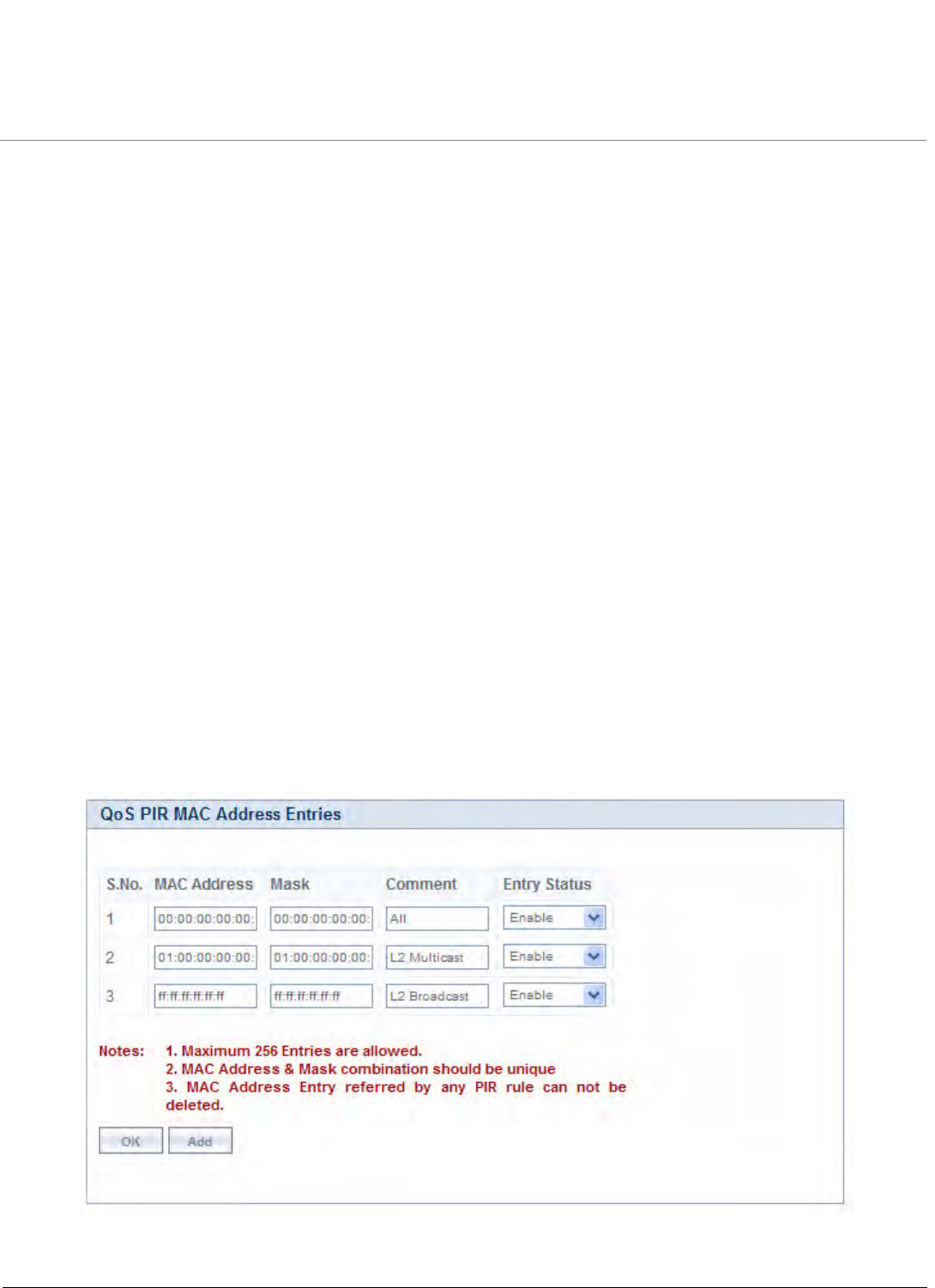
Advanced Configuration
Tsunami QB-8100 Series (100 Mbps/5 Mbps Models) Installation and Management Guide 75
– PIR: Vonage VoIP UL; PIR Priority: 1
– PIR: Cisco VoIP UL; PIR Priority: 1
b. SF class: DL-G729 20 ms VoIP rtPS
– PIR: Vonage VoIP DL; PIR Priority: 1
– PIR: Cisco VoIP DL; PIR Priority: 1
5. 2Mbps Video
a. SF class: DL-2Mbps Video
– PIR: Streaming Video (IP/TV); PIR Priority: 1
4.6.2 QoS Configuration
There are several pre-defined QoS classes, SFCs, and PIRs available that cover the most common types of traffic. If you want
to configure something else, build the hierarchy of a QoS class as follows:
1. Define PIR MAC Address, IP Address and TCP/UDP Port Entries.
2. Define PIRs and specify packet clarification rules, associate MAC Address/IP Address/TCP-UDP Port Entries if required.
3. Define SFCs
4. Define QoS Class by associating PIRs with relevant SFC.
5. Assign priorities to each PIR within each SFC.
For instructions on configuring a management station (a single station used for managing an entire network), see QoS
Configuration for a Management Station.
QoS PIR MAC Address Configuration
1. Click ADVANCED CONFIGURATION > QoS > PIR List > MAC Address Entries.
2. Three predefined MAC Address entries are displayed in this page. You can configure maximum 256 entries. MAC
Address and Mask combination should be unique. This MAC Address entry can be referred in the PIR Rule’s Source or
Destination MAC Address Classification. MAC Entry referred by any PIR rule cannot be deleted.
Figure 4-16 QoS PIR MAC Address Entries
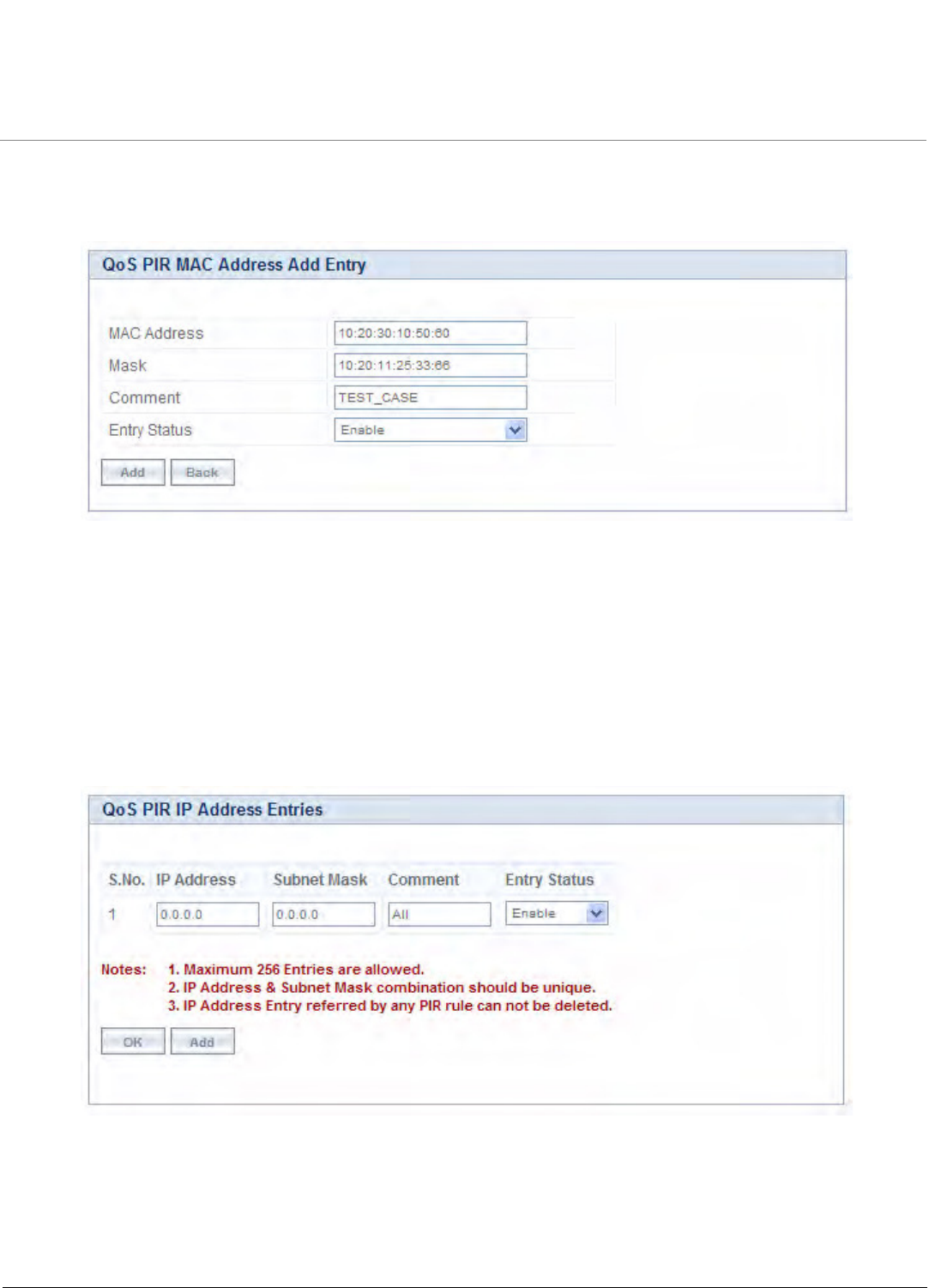
Advanced Configuration
Tsunami QB-8100 Series (100 Mbps/5 Mbps Models) Installation and Management Guide 76
3. Add a New PIR MAC Address Entry
a. Click Add to add a new entry. The following screen appears for configuring the MAC Entry Details.
Figure 4-17 QoS PIR MAC Address Add Entry
b. Provide the MAC Address, Mask, Comment, Entry Status details and click Add. Comment field can be used to
identify when this particular entry is referred in PIR Rule/QoS Class.
QoS PIR IP Address Configuration
1. Click ADVANCED CONFIGURATION > QoS > PIR List > IP Address Entries. A single predefined IP Address entry is
displayed. You can configure maximum 256 entries. IP Address, Subnet Mask combination should be unique. This IP
Address entry can be referred in the PIR Rule’s Source or Destination IP Address Classification. IP Address Entry referred
by any PIR rule cannot be deleted.
Figure 4-18 QoS PIR IP Address Entries
2. Add a New PIR IP Address Entry.
a. Click Add to add a new entry. The following screen appears for configuring the IP Address Entry Details.
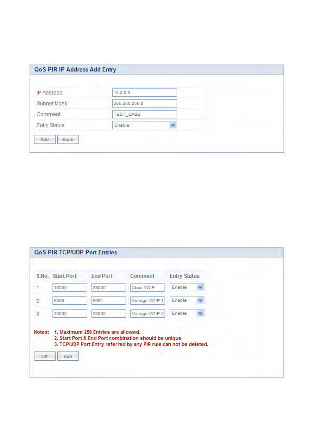
Advanced Configuration
Tsunami QB-8100 Series (100 Mbps/5 Mbps Models) Installation and Management Guide 77
Figure 4-19 QoS PIR IP Address Add Entry
b. Provide the IP Address, Subnet Mask, Comment, Entry Status details and click Add. Comment field can be used by
the user to identify when this particular entry is referred in PIR Rule/QoS Class.
QoS PIR TCP/UDP Port Configuration
1. Click ADVANCED CONFIGURATION > QoS > PIR List > TCP/UDP Port Entries. Three predefined TCP/UDP Port
Entries are displayed. You can configure maximum 256 entries. Start Port, End Port combination should be unique.
This TCP/UDP Port entry can be referred in the PIR Rule’s Source or Destination TCP/UDP Port Classification. TCP/UDP
Port Entry referred by any PIR rule can not be deleted.
Figure 4-20 QoS PIR TCP/UDP Port Entries
2. Add a New PIR TCP/UDP Port Entry.
a. Click Add to add a new entry. The following screen appears for configuring the IP Address entry details.
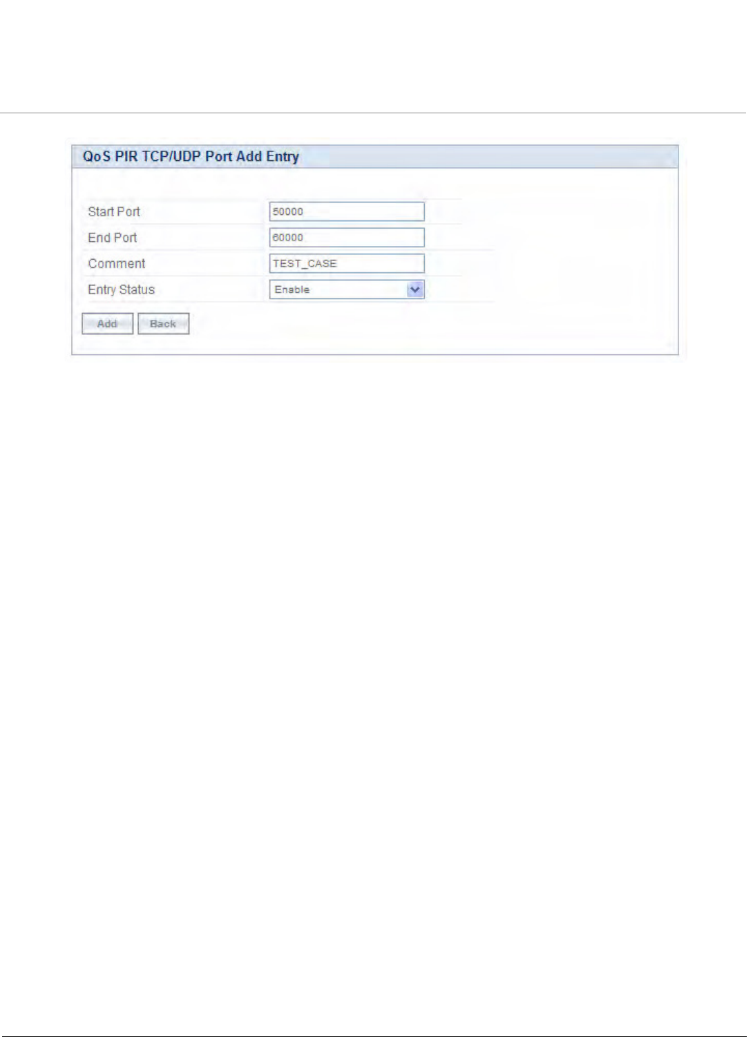
Advanced Configuration
Tsunami QB-8100 Series (100 Mbps/5 Mbps Models) Installation and Management Guide 78
Figure 4-21 QoS PIR TCP/UDP Port Add Entry
b. Provide the Start Port, End Port, Entry Status details and click Add. Comment field can be used to identify when
this particular entry is referred in PIR Rule/QoS Class.
4.6.2.1 QoS PIR Configuration
1. Click ADVANCED CONFIGURATION > QoS > PIR List. 18 predefined PIR Rules are displayed in this page. You can
configure maximum 64 entries. PIR Rule Name should be unique. This PIR Rule can be referred in the QoS Class’s
Service Flow Details. PIR rule referred by any QoS Class cannot be deleted.
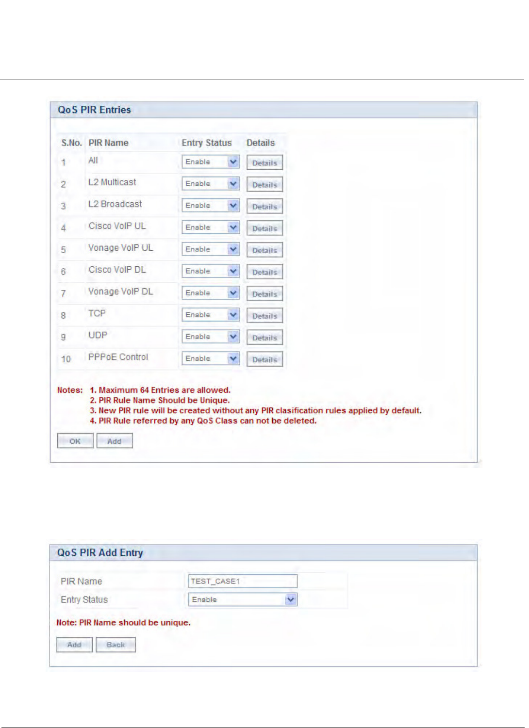
Advanced Configuration
Tsunami QB-8100 Series (100 Mbps/5 Mbps Models) Installation and Management Guide 79
Figure 4-22 QoS PIR Entries
2. Add a New PIR Rule.
a. Click Add to add a new entry. The following screen appears for configuring the New PIR Entry.
Figure 4-23 QoS PIR Add Entry
b. Provide the PIR Name, Entry Status details and click Add.
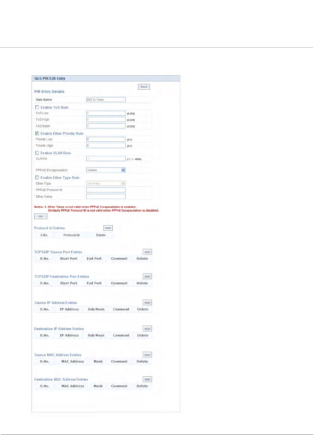
Advanced Configuration
Tsunami QB-8100 Series (100 Mbps/5 Mbps Models) Installation and Management Guide 80
PIR Rule Clarification Details
1. Click ADVANCED CONFIGURATION > QoS > PIR List and click Details for editing a particular PIR Rule.
Figure 4-24 QoS PIR Edit Entry

Advanced Configuration
Tsunami QB-8100 Series (100 Mbps/5 Mbps Models) Installation and Management Guide 81
Parameter Description
Rule Name This parameter specifies the Name of the Packet Identification Rule
(PIR) and can have a length of 1-32 characters.
ToS Rule This parameter is used to enable/disable TOS rule. Enter the values
for the following to specify the ToS-related configuration:
ToS Low
ToS High
ToS Mask
Ether Priority Rule This parameters is used to enable or disable 802.1p priority rule.
Enter the values for the following to specify 802.1p priority
configuration:
Priority Low
Priority High
VLAN Rule This parameters allows to enable or disable VLAN rule. Enter the
VLAN ID when the VLAN rule is enabled.
PPPoE Encapsulation This parameter is used to classify PPPoE traffic.
NOTE:
•Enabling/disabling PPPoE Configuration will
automatically disable Ether Type Rule. User can
configure it again by enabling Ether Type Rule.
•When PPPoE Encapsulation is enabled, incoming
packet will be checked again Ether value “0x8864” and
look for PPPoE Protocol Id value “0x0021”(IP Protocol)
by default. User can modify the PPPoE Protocol Id. All
other classification rules which are specified in the PIR
rule will work only if the PPPoE Protocol Id is “0021”.
•Ether Value is not valid when PPPoE Encapsulation is
enabled.
Ether Type Rule This parameters is used to enable/disable Ether Type rule. Enter the
values for the following to specify the Ether Type rule related
configuration:
Ether Type
PPPoE Protocol Id
Ether Value
NOTE:
•PPPoE Protocol Id is not valid if PPPoE Encapsulation is
disabled.
•Ether Value is not valid if PPPoE Encapsulation is
enabled.
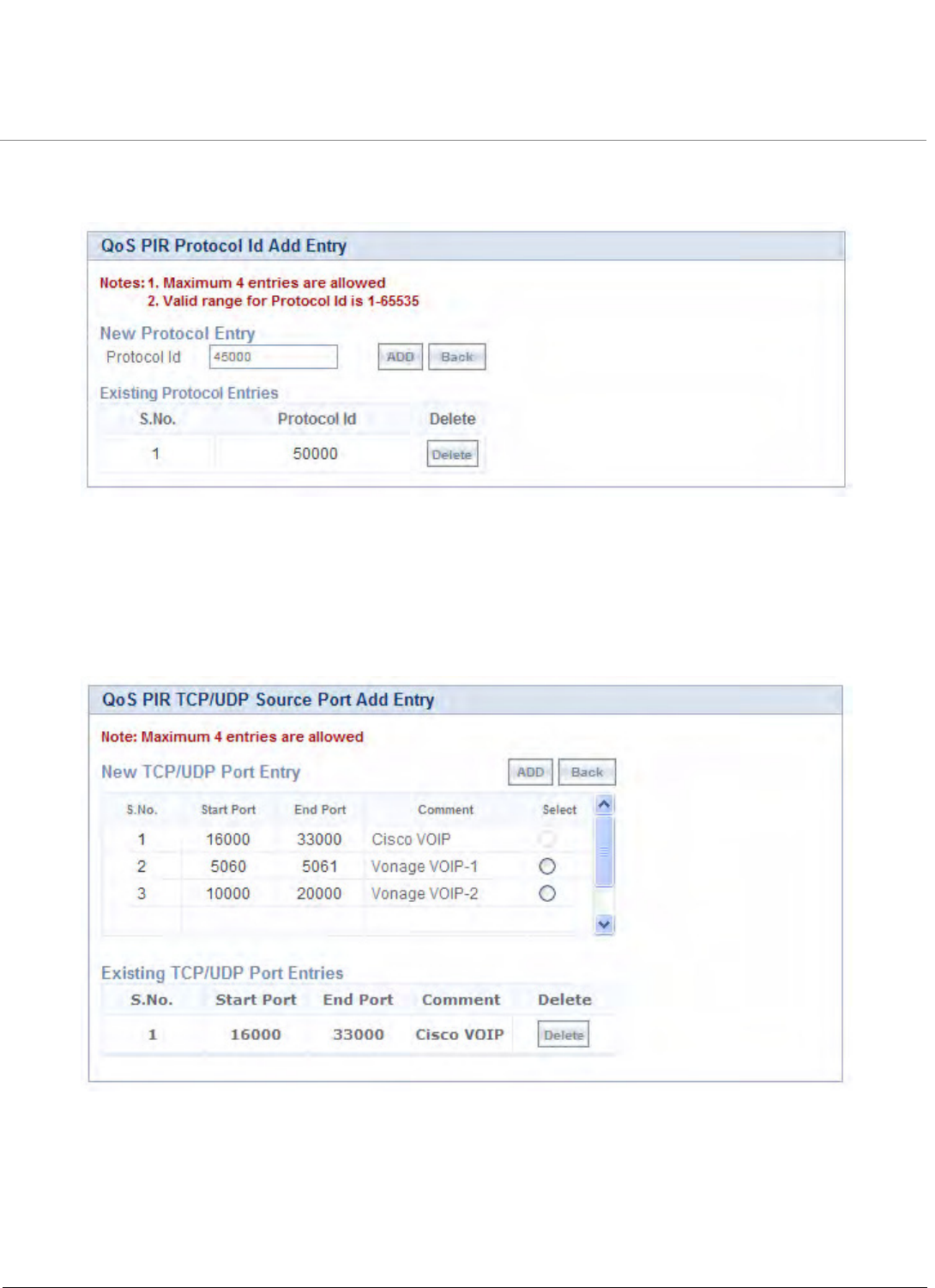
Advanced Configuration
Tsunami QB-8100 Series (100 Mbps/5 Mbps Models) Installation and Management Guide 82
Adding Protocol ID
a. Click Add to add a new Protocol entry. The following screen appears.
Figure 4-25 QoS PIR Protocol ID
b. Enter the details and click Add. For deleting an entry, click Delete for the corresponding entry in PIR Details
page.
Adding TCP/UDP Source Port Numbers
a. Click Add to add a new entry. The following screen appears.
Figure 4-26 QoS PIR TCP/UDP Source Port Add Entry
b. All the Entries present in the PIR TCP/UDP Port Entries are displayed in the TCP/UDP Port Entry Table. Select the
appropriate radio button and click Add. After adding the entry for this specific PIR, it is displayed in the Existing
TCP/UDP Port Entries table. For deleting an entry, click Delete for the corresponding entry in the PIR Details page.
Adding TCP/UDP Destination Port Numbers
a. Click Add to add a new entry. The following screen appears.
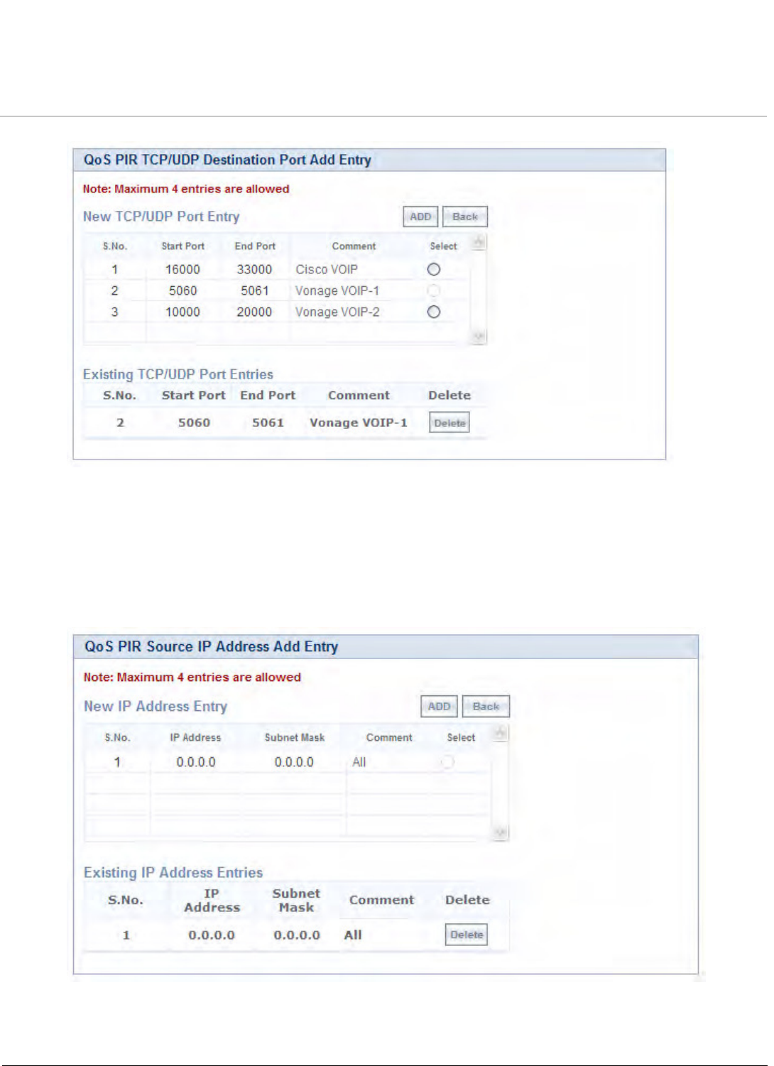
Advanced Configuration
Tsunami QB-8100 Series (100 Mbps/5 Mbps Models) Installation and Management Guide 83
Figure 4-27 QoS PIR TCP/UDP Destination Port Add Entry
b. All the entries present in the PIR TCP/UDP Port Entries are displayed in the TCP/UDP Port Entry Table. Select the
appropriate radio button and click Add. After adding the entry for this specific PIR, it is displayed in the Existing
TCP/UDP Port Entries table. For deleting an entry, click Delete for the corresponding entry in the PIR Details page.
Adding Source IP Address
a. Click Add to add a new entry. The following screen appears.
Figure 4-28 QoS PIR Source IP Address Add Entry
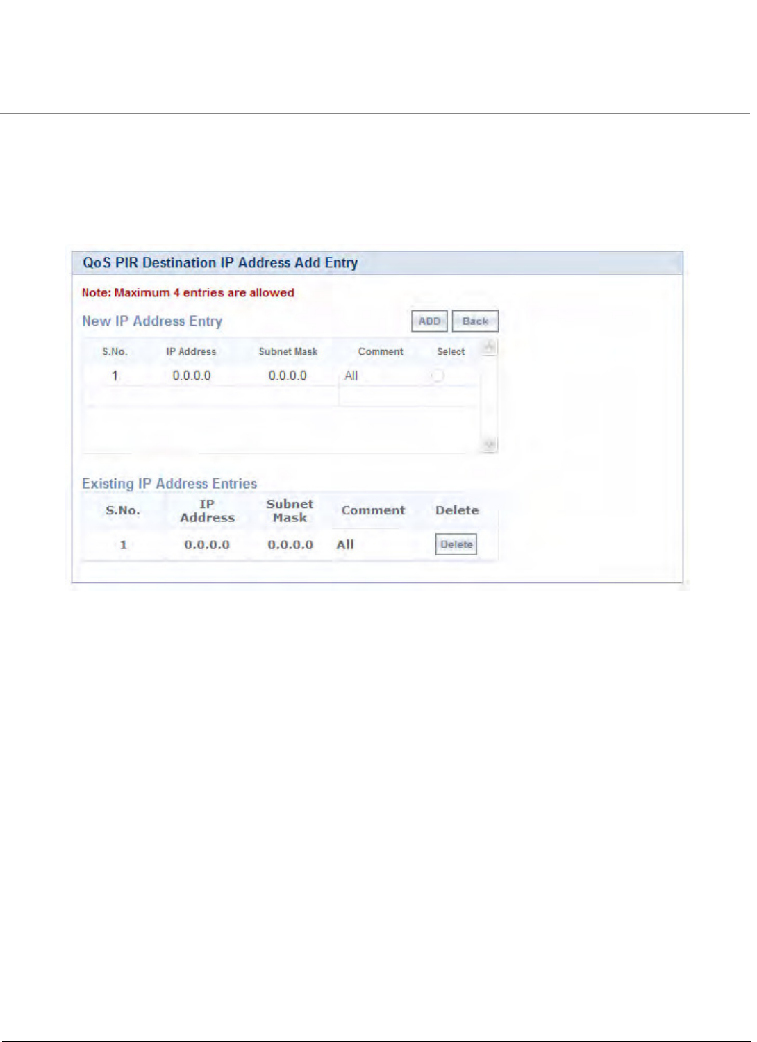
Advanced Configuration
Tsunami QB-8100 Series (100 Mbps/5 Mbps Models) Installation and Management Guide 84
b. All the entries present in the PIR IP Address Entries are displayed in the IP Address Entry Table. Select the
appropriate radio button and click Add. After adding the entry for this specific PIR, it is displayed in the Existing IP
Address Entries table. For deleting an entry, click Delete for the corresponding entry in the PIR Details page.
Adding Destination IP Address
a. Click Add to add a new entry. The following screen appears.
Figure 4-29 QoS PIR Destination IP Address Add Entry
b. All the entries present in the PIR IP Address Entries are displayed in the IP Address Entry Table. Select the
appropriate radio button and click Add. After adding the entry for this specific PIR, it is displayed in the Existing IP
Address Entries table. For deleting an entry, click Delete for the corresponding entry in the PIR Details page.
Adding Source MAC Address
a. Click Add to add a new entry. The following screen appears.
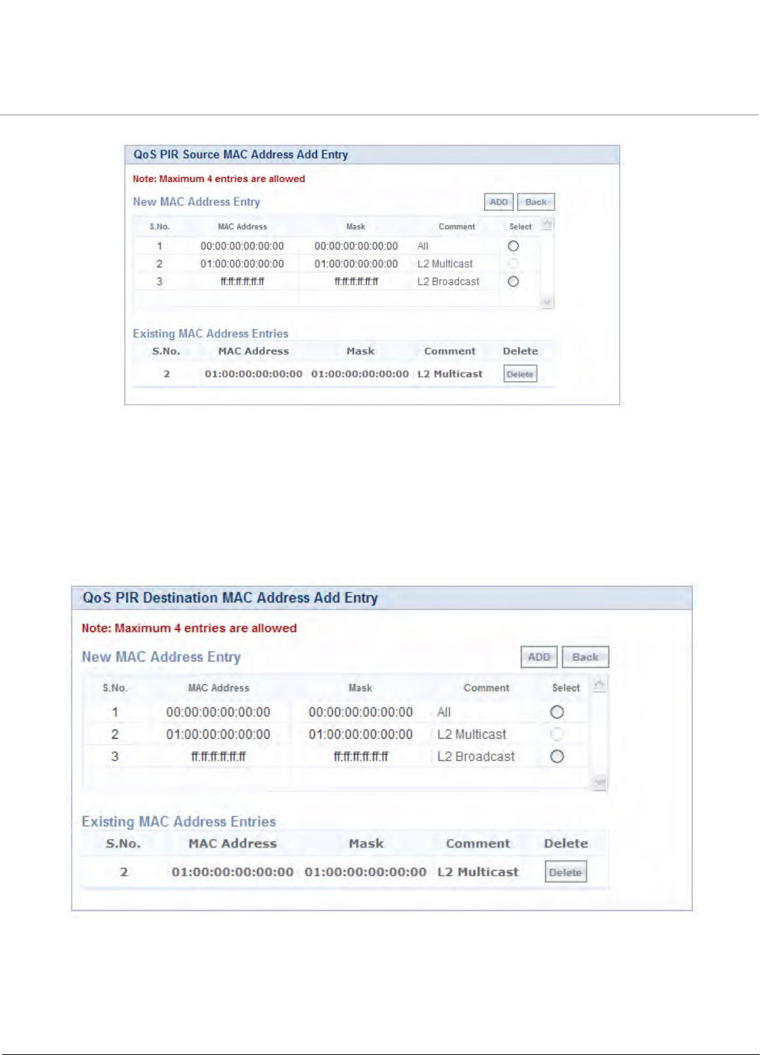
Advanced Configuration
Tsunami QB-8100 Series (100 Mbps/5 Mbps Models) Installation and Management Guide 85
Figure 4-30 QoS PIR Source MAC address Add Entry
b. All the entries present in the PIR MAC Address Entries are displayed in the MAC Address Entry Table. Select the
appropriate radio button and click Add. After adding the entry for this specific PIR, it is displayed in the Existing
MAC Address Entries table. For deleting an entry, click Delete for the corresponding entry in the PIR Details page.
Adding Destination MAC Address
a. Click Add to add a new entry. The following screen appears.
Figure 4-31 QoS PIR Destination MAC address Add Entry
b. All the entries present in the PIR MAC Address Entries are displayed in the MAC Address Entry Table. Select the
appropriate radio button and click Add. After adding the entry for this specific PIR, it is displayed in the Existing
MAC Address Entries table. For deleting an entry, click Delete for the corresponding entry in the PIR Details page.
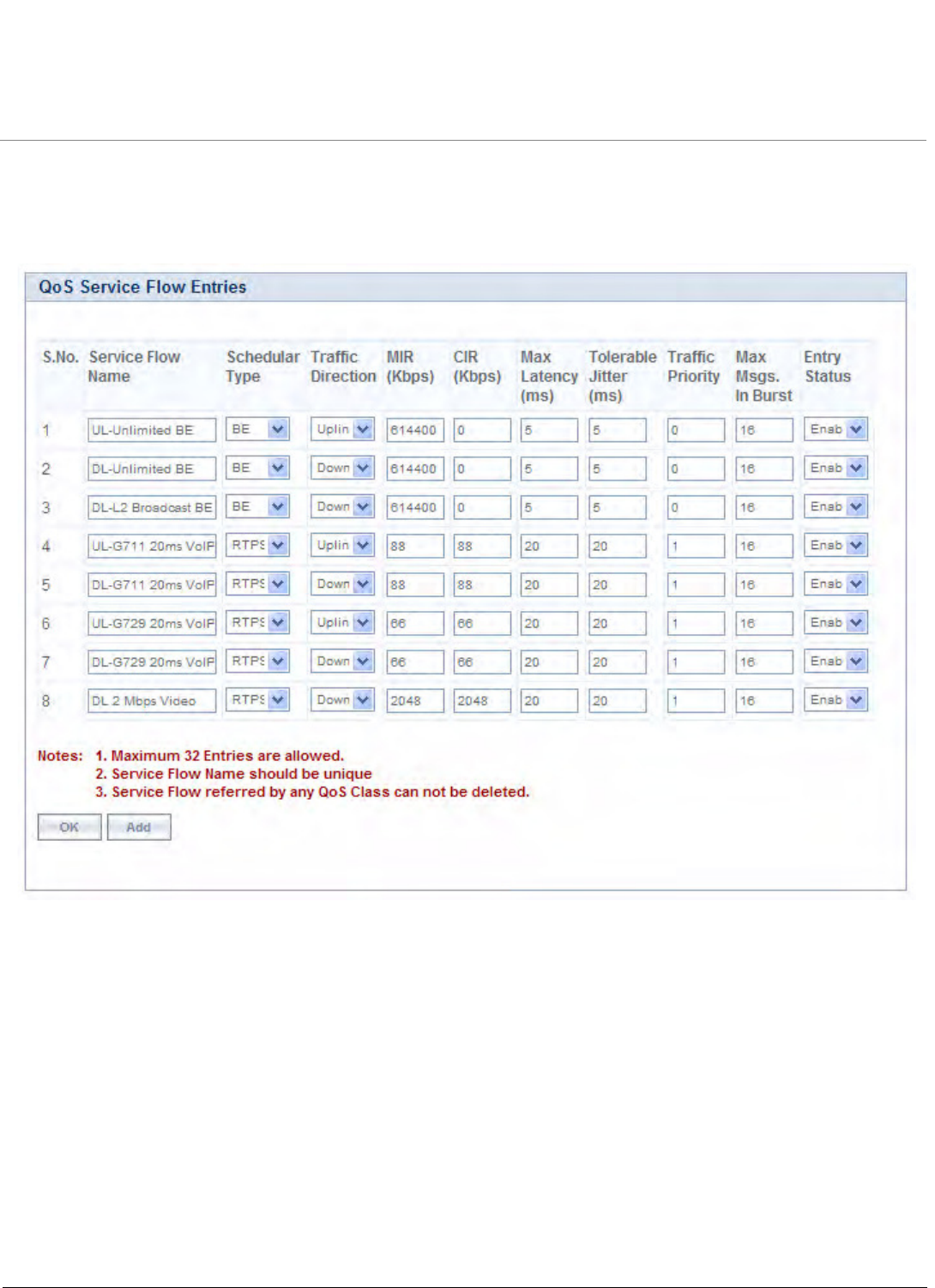
Advanced Configuration
Tsunami QB-8100 Series (100 Mbps/5 Mbps Models) Installation and Management Guide 86
4.6.2.2 QoS Service Flow Configuration (SFC)
1. Click ADVANCED CONFIGURATION > QoS > SFC List. Eight predefined SFCs are displayed in this page. This table
allows the user to configure maximum of 32 entries. Service Flow Name should be unique. This SFC can be referred in
the QoS Class’ Details. SFC referred by any QoS Class cannot be deleted.
Figure 4-32 QoS Service Flow Entries
Adding a New Service Flow (SFC):
a. Click Add to add new entry. The following screen appears for configuring the New PIR Entry.
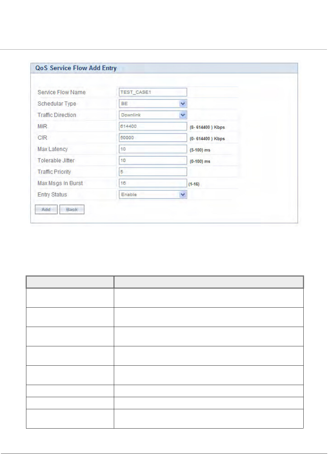
Advanced Configuration
Tsunami QB-8100 Series (100 Mbps/5 Mbps Models) Installation and Management Guide 87
Figure 4-33 QoS Service Flow Add Entry
2. Specify details for the Service Flow Name, Scheduler Type, Traffic Direction, MIR, CIR, Max Latency, Tolerable Jitter,
Traffic Priority, Max Messages in Burst and Entry Status.
3. Click Add.
Parameter Description
Service Flow Name Specifies the Name of the Service Flow. It can be of length 1-32
characters.
Scheduler Type Specifies the Scheduler methods to be used. Scheduler type supports
BE (Best Effort), RTPS (Real-Time Polling Service).
Traffic Direction Specifies the Direction (Downlink or Uplink) of the traffic in which the
configuration has to be matched.
MIR (Maximum Information
Rate)
Specifies the maximum bandwidth allowed for this Service Flow. This
value ranges from 88 to maximum value specified in the license file.
CIR (Committed Information
Rate)
Specifies the reserved bandwidth allowed for this Service Flow. This
value ranges from 0 to maximum value specified in the license file.
Max Latency Specifies the Latency value. This value ranges from 5 to 100 ms.
Tolerable Jitter Specifies the Jitter value. This value ranges from 0 to 100 ms.
Traffic Priority Specifies the priority of the Service flow when multiple Service flows
are assigned to single QoS Class. This value ranges from 0 to 7.
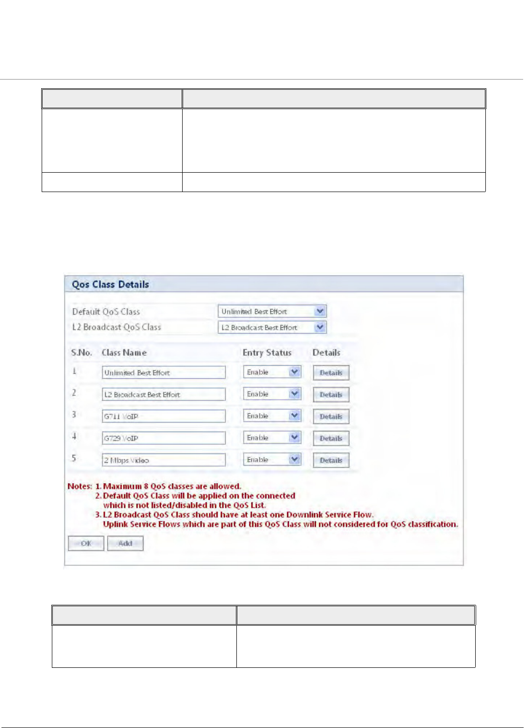
Advanced Configuration
Tsunami QB-8100 Series (100 Mbps/5 Mbps Models) Installation and Management Guide 88
4.6.2.3 QoS Class Configuration
1. Click ADVANCED CONFIGURATION > QoS > Class List. Five predefined QoS Classes are displayed in this page.
You can configure maximum 8 entries. QoS Class Name should be unique. This QoS Class can be referred in the
Default QoS Class or L2 Broadcast QoS Class. Any QoS Class referred cannot be deleted.
Figure 4-34 QoS Class Details
Max Messages in Burst Specifies the maximum number of messages that can be sent in a
burst. This value ranges from 1 to 16.
NOTE: Reducing the number of messages impacts the
throughput.
Entry Status Specifies the Service Flow status.
Parameter Description
Default QoS Class This parameter specifies the QoS Class profile that
needs to be associated with an End Point which is not
listed in the QoS End Point List but connected.
Parameter Description
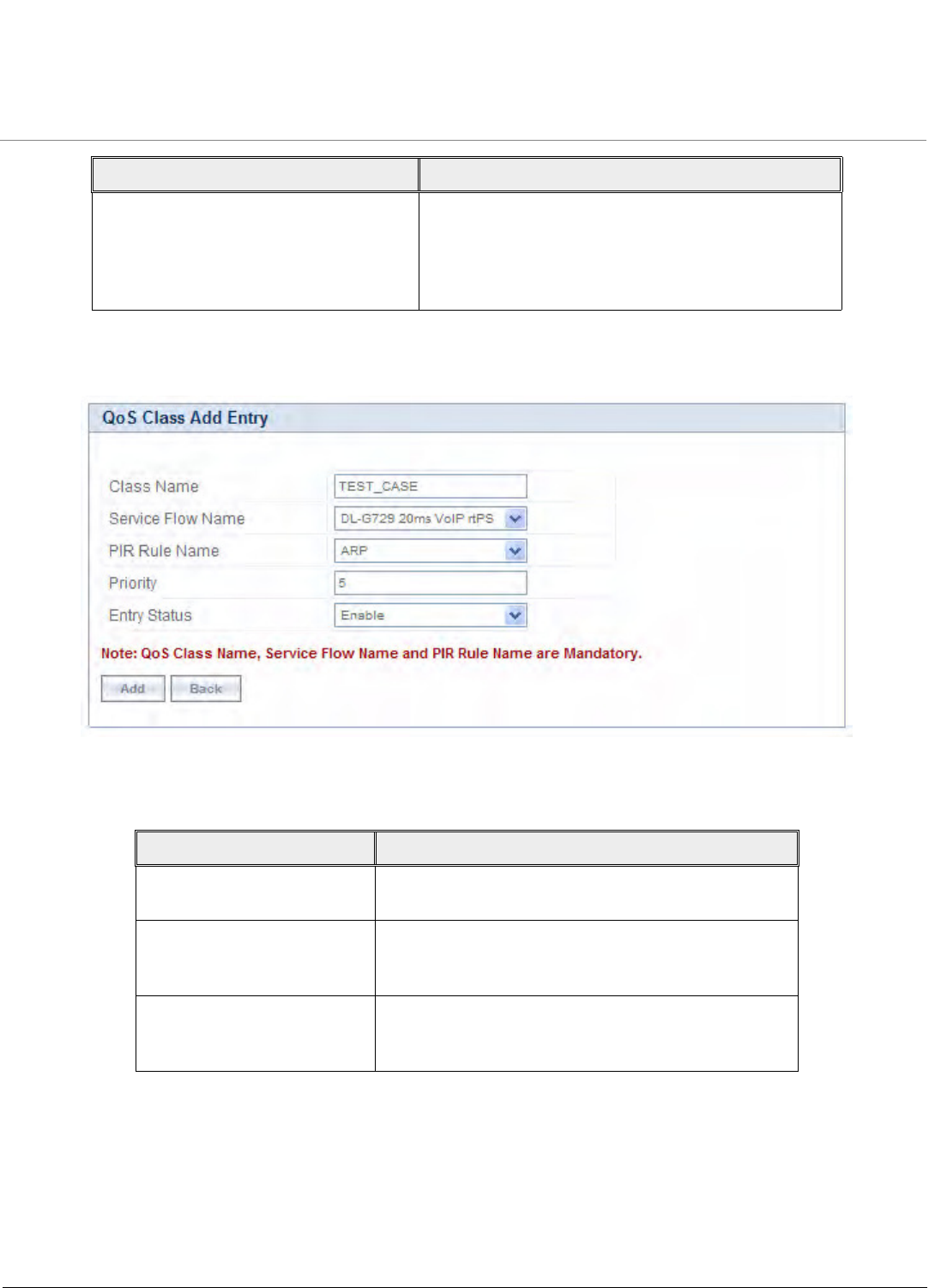
Advanced Configuration
Tsunami QB-8100 Series (100 Mbps/5 Mbps Models) Installation and Management Guide 89
4. Add a New QoS Class:
a. Click Add to add new entry. The following screen appears for configuring the New Class Entry.
Figure 4-35 QoS Class Add Entry
b. Specify the QoS Class Name, Service Flow Name PIR Rule Name Priority and Entry Status and click Add.
L2 Broadcast QoS Class This parameter specifies WORP to use this particular
class for worp broadcast facility.
L2 Broadcast QoS Class is valid only for Downlink
Direction. QoS Class assigned to this profile should
have at least one Downlink SFC.
Parameter Description
Class Name Specifies the Name of the QoS Class. This name length
can range from 1 to 32 characters.
Service Flow Name Specifies the Service Flow to be associated with the
QoS Class. Select one of the possible SFCs that have
been previously configured in the SFC List.
PIR Rule Name Specifies the PIR Rule need to be associated with this
Service Flow. Select one of the possible PIRs that have
been previously configured in the PIR List.
Parameter Description
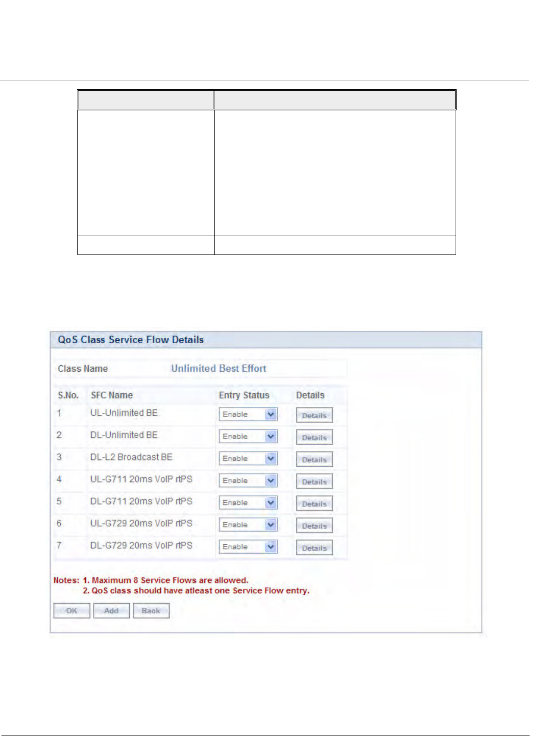
Advanced Configuration
Tsunami QB-8100 Series (100 Mbps/5 Mbps Models) Installation and Management Guide 90
Adding Service Flows in QoS Class
1. Click on the corresponding Details of the QoS Class for adding more Service Flows. Each QoS Class can have
maximum 8 Service Flows. At least there should be one service flow per QoS Class. The following screen is displayed
to configure the new SFC entry inside the QoS Class.
Figure 4-36 QoS Class Service Flow Details
2. Click Add. The following screen appears for association of the new SFC in this QoS Class.
Priority Specifies priority or order of execution of PIRs during
packet identification process. The PIR priority is a
number that can range from 0-63, with priority 63
being executed first, and priority 0 being executed last.
The PIR priority is defined within a QoS class, and can
be different for the same PIR in some other QoS class.
If all PIRs within one QoS class have the same priority,
the order of execution of PIR rules will be defined by
the order of definition of SFCs, and by the order of
definition of PIRs in each SFC, within that QoS class.
Entry Status Specifies the status of the QoS Class as enable/disable.
Parameter Description
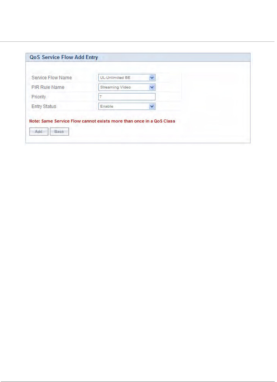
Advanced Configuration
Tsunami QB-8100 Series (100 Mbps/5 Mbps Models) Installation and Management Guide 91
Figure 4-37 QoS Class Service Flow Add Entry
3. Specify the Service Flow Name, PIR Rule Name, Priority and Entry Status and click Add to add a new entry.
Adding PIR in QoS Class
1. Click on the corresponding Details provided in the Service Flow of a particular QoS Class. Maximum 8 PIR rules can be
associated per SFC of an QoS Class. At least there should be one PIR per SFC of an QoS Class. The following screen
will be displayed to associate the new PIR entry inside an SFC of an QoS Class.
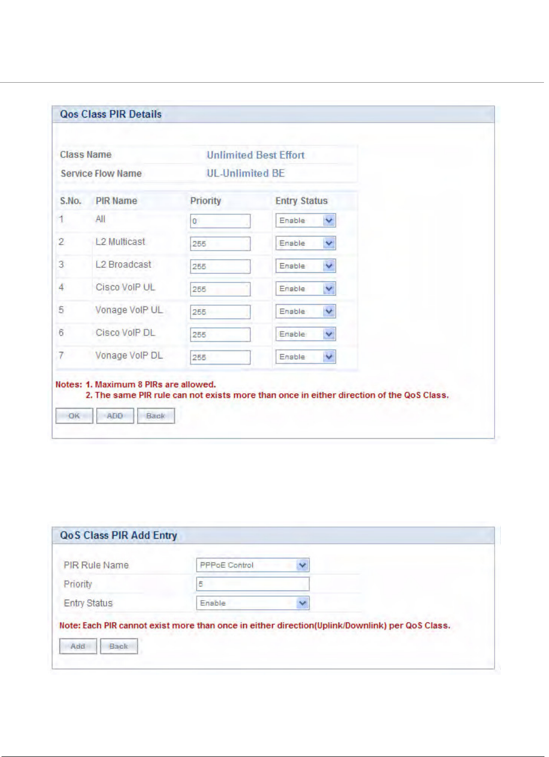
Advanced Configuration
Tsunami QB-8100 Series (100 Mbps/5 Mbps Models) Installation and Management Guide 92
Figure 4-38 QoS Class PIR Details
2. Click Add. The following screen appears for association of the new PIR rule in an SFC already associated in an QoS
Class.
Figure 4-39 QoS Class PIR Add Entry
3. Specify the PIR Rule Name, Priority and Entry Status and click Add to add a new entry.
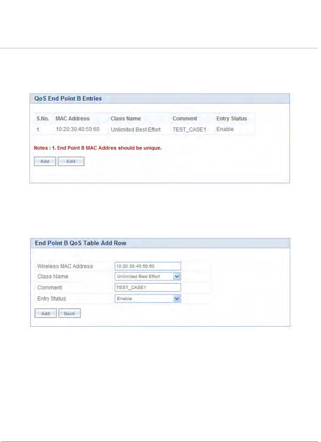
Advanced Configuration
Tsunami QB-8100 Series (100 Mbps/5 Mbps Models) Installation and Management Guide 93
4.6.2.4 QoS End Point Configuration
1. Click ADVANCED CONFIGURATION > QoS > End Point. By default, the table does not have any entry. User can
configure the Wireless MAC Address of the End Point B here and associate the QoS Class need to be used for that
particular End Point.
Figure 4-40 QoS End Point B Entries
If no End Point is configured but any End point is associated then this End Point gets the Default QoS Class
configuration.Adding a New End Point
1. Click Add to add a new entry. The following screen appears for configuring the New End Point Entry.
Figure 4-41 End Point B QoS Table add Row
2. Specify the Wireless Mac Address of the End Point, Class Name, Comment and Entry Status and click Add. Previously
defined Class Name is listed in the Class Name drop-down menu.
4.6.3 QoS Configuration for a Management Station
As stated previously, the QoS feature enables prioritization of traffic and allocation of the available bandwidth based on that
prioritization. The system is designed in such a way that higher priority traffic preempts lower priority traffic, keeping lower
priority traffic on hold until higher priority traffic finishes. This mechanism ensures that the available bandwidth is always
given first to the higher priority traffic; if all the bandwidth is not consumed, the remaining bandwidth is given to the lower
priority traffic.

Advanced Configuration
Tsunami QB-8100 Series (100 Mbps/5 Mbps Models) Installation and Management Guide 94
If QoS is not configured properly, the system can become difficult to access in heavily loaded networks. One of the side effects
of this misconfiguration is ping time-out, which is usually interpreted as a disconnection of the pinged node. However, with
the correct QoS configuration, every node in the network can be reached at any moment.
The following configuration instructions explain how to configure the system so that configuration parameters can always be
changed, and ping requests and responses get higher priority in order to show the actual connectivity of the pinged node.
The configuration suggested here assumes that the whole network is managed from a single work station, called the
management station. This station can be connected anywhere in the network, and can be recognized by either its IP address,
or by its MAC Ethernet address if the network uses DHCP.
In this configuration, any traffic coming from or going to the management station is treated as management traffic.
Therefore, the management station should be used only for configuration of the Quick Bridge nodes in the network and to
check connectivity of the nodes, but it should not be used for any throughput measurements.
CAUTION: While this QoS configuration is used, the TCP or UDP throughput should not be measured from the
management station.
Step 1: Add Packet Identification Rules
To recognize management traffic, the system needs to recognize ARP requests/responses and any traffic coming from or
going to the management station.
A. Confirm the Attributes of the Existing ARP PIR
The default QoS configuration contains the PIR called “ARP,” which recognizes ARP requests/responses by the protocol
number 0x0806 in the Ethernet Type field of the Ethernet packet. Confirm that the ARP PIR parameters are correct, as
follows:
1. Click ADVANCED CONFIGURATION > QoS > PIR list.
2. Click the Details button corresponding to the ARP PIR.
3. Confirm the following attributes:
•Rule Name: ARP
•Status: Enable
•Enable Ether Type Rule: Yes (checkbox is selected)
— Ether Type: DIX-Snap
— Ether Value: 08:06(hex)
B. Create New PIRs to Recognize Management Traffic
To recognize the traffic coming from or going to the management station, the system must contain two additional PIRs: one
with either the destination IP address or the destination MAC address equal to the management station’s IP or MAC address,
and another with either the source IP address or the source MAC address equal to the management station’s IP or MAC
address. The following examples explain PIR rules based on the IP Address of the Management Station.
1. Click ADVANCED CONFIGURATION > QoS > PIR list > IP Address Entries.
2. Click Add. The screen for adding the Management Station's IP Address appears. Enter proper IP Address, Subnet
mask as 255.255.255.255, Entry status as Enable and then click Add. This adds the Management Station’s IP details
in the IP Address Entries of the PIR List.
3. Click ADVANCED CONFIGURATION > QoS > PIR list.
4. Add PIR Rule for Source IP Address.
a. Click Add. The screen for adding the New PIR Rule appears. Enter the PIR Rule Name as “Management Station
SRC IP”, Entry status as Enable and click Add. This adds the new PIR rule in the PIR List. By default, no
classification rules are applied.
b. Click ADVANCED CONFIGURATION > QoS > PIR list. Click Details for “Management Station SRC IP” PIR rule.
This displays all the classification rule details for this particular rule.

Advanced Configuration
Tsunami QB-8100 Series (100 Mbps/5 Mbps Models) Installation and Management Guide 95
c. Click Add that corresponds to Source IP Address Entries. This displays a screen for referring the Management
Station’s IP Address. New Entry Table displays all the IP Address Entries of the PIR List. Select the option button
corresponding to the Management Station and then click Add. This adds the IP Address of the Management
Station to the Existing Entries. Click Back and the new entry appears in the Source IP Address Entries Table.
5. Add PIR Rule for Destination IP Address.
a. Click Add. This displays a screen for adding the New PIR Rule. Enter the PIR Rule Name as “Management Station
DST IP”, Entry status as Enable and then click Add. This adds the new PIR rule in the PIR List. By default, no
classification rules are applied.
b. Click ADVANCED CONFIGURATION > QoS > PIR list. Click Details corresponding to the “Management Station
DST IP” PIR rule. This displays the classification rule details for this particular rule.
c. Click Add corresponding to Destination IP Address Entries. This displays a screen for referring the Management
Station’s IP Address. New Entry Table displays all the Entries of the IP Address Entries of the PIR List. Select the
option button corresponding to the Management Station and click Add. This adds the IP Address of the
Management Station to the Existing Entries. Click Back and the new entry appears in the Destination IP Address
Entries Table.
Step 2: Add Service Flow Classes
To handle management traffic, the system needs two Service Flow Classes: one for uplink traffic and one for downlink traffic.
1. Configure the Downlink Service Flow.
a. Click ADVANCED CONFIGURATION > QoS > SFC list.
b. Click Add.
c. Enter the following parameters:
•Service Flow Name: DL-Management
•Scheduler Type: RtPS
•Traffic Direction: Downlink
•MIR: 1000
•CIR: 1000
•Max Latency: 20
•Tolerable Jitter: 10
•Priority: 7
•Max Messages in Burst: 16
•Entry Status: Enable
d. Click Add. The DL-Management Service Flow is added to the QoS SFC List.
2. Configure the Uplink Service Flow.
a. Click ADVANCED CONFIGURATION > QoS > SFC list.
b. Click Add.
c. Enter the following parameters:
•Service Flow Name: UL-Management
•Scheduler Type: RtPS
•Traffic Direction: Uplink
•MIR: 1000
•CIR: 1000
•Max Latency: 20
•Tolerable Jitter: 10
•Priority: 7

Advanced Configuration
Tsunami QB-8100 Series (100 Mbps/5 Mbps Models) Installation and Management Guide 96
•Max Messages in Burst: 16
•Entry Status: Enable
d. Click Add. The UL-Management SF is added to the QoS SFC List.
NOTE: The input and output bandwidth limits set on the End Point A or on the End Point B are used for limiting
aggregate bandwidth used by End Point B. These limits override any limit imposed by MIR in the SFC. Therefore,
these limits should be set to at least 1000 kbps (MIR values in UL-Management and DL-Management SFCs).
Step 3: Configure QoS Classes
Finally, the DL-Management SFC and UL-Management SFCs created in Step 2 must be added to each QoS Class used by the
Quick Bridge network. Additionally, within the QoS class, these SFC must have the three PIRs mentioned in Step 1 associated
with them.
1. Add SFCs to QoS Class.
a. Click ADVANCED CONFIGURATION > QoS > Class list.
b. Click Details corresponding to the first class (Unlimited Best Effort) you wish to modify.
c. Under the QoS Class Service Flow, click Add.
d. Configure the following parameters, and click Add. This adds the New SFC & PIR relation to the QoS Class.
•Service Flow Name: DL-Management
•PIR Rule Name: ARP
•PIR Priority: 63
•Entry Status: Enable.
e. Again click Add under the QoS Class Service Flow Details.
f. Configure the following parameters and click Add. This adds the New SFC & PIR relation to the QoS Class.
•Service Flow Name: UL-Management
•PIR Rule Name: ARP
•PIR Priority: 63
•Entry Status: Enable
2. Add PIRs to SFCs within the QoS Class.
a. Click ADVANCED CONFIGURATION > QoS > Class list.
b. Click Details corresponding to the first class (Unlimited Best Effort) you wish to modify.
c. Under the QoS Class Service Flow Details heading, click Details corresponding to the DL-Management Service
Flow.
d. Under the QoS Class PIR Details heading, click Add.
e. Add the Management Station DST IP PIR to this Service Flow by configuring the following parameters:
•PIR Rule Name: Management Station DST IP
•PIR Priority: 63
•Entry Status: Enable
f. Click Add. This PIR is added to the first Qos Class (Unlimited Best Effort) Service Flow’s (DL-Management) list.
g. Add the Management Station SRC IP PIR to this Service Flow by configuring the following parameters:
•PIR Rule Name: Management Station SRC IP
•PIR Priority: 63
•Entry Status: Enable
h. Return to the Class List screen and repeat steps 2 - 7 for the UL-Management Service Flow in this class.
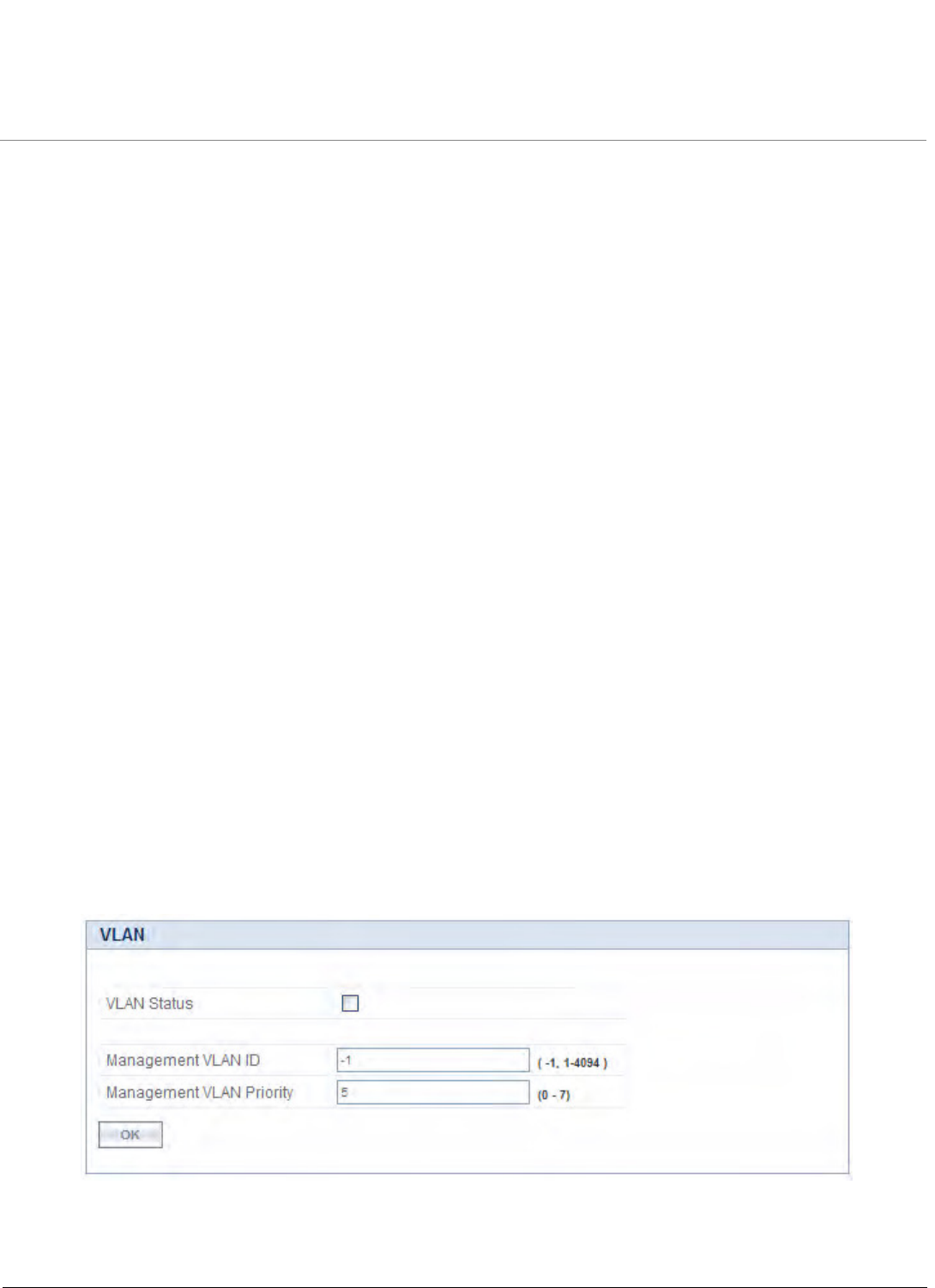
Advanced Configuration
Tsunami QB-8100 Series (100 Mbps/5 Mbps Models) Installation and Management Guide 97
4.7 VLAN Configuration (Bridge Mode only)
Virtual Local Area Networks (VLANs) are logical groupings of network hosts. Defined by software settings, other VLAN
members or resources appear (to connected hosts) to be on the same physical segment, no matter where they are attached
on the logical LAN or WAN segment. They simplify traffic flow between clients and their frequently-used or restricted
resources.
A device can communicate across a VLAN-capable switch that analyses VLAN tagged frames and directs traffic to the
appropriate units. The purpose of this network is to provide an easy way of modifying logical groups in the dynamic
environment. VLAN is supported only in Bridge mode.
VLANs are used to conveniently, efficiently, and easily manage your network in the following ways:
•Define groups
•Reduce broadcast and multicast traffic to unnecessary destinations
– Improve network performance and reduce latency
•Increase security
– Secure network restricts members to resources on their own VLAN
VLAN features can be managed via:
•The End Point’s Web interface
•The Command Line Interface (see “Command Line Interface” section in the Reference Manual)
•SNMP (Log on to Proxim support site http://support.proxim.com for MIBs)
NOTE: The VLAN parameters can be configured on selected Interface (Ethernet 1/Ethernet 2).
4.7.1 Establishing a VLAN Connection
For enabling the VLAN support, certain network settings should be configured and certain network resources, such as VLAN
aware switches should be available, depending upon the type of configuration.
VLAN support also provides the capability to specify a separate VLAN ID and priority for management frames (SNMP, ICMP,
Telnet, DHCP, and TFTP).
To configure VLAN,
Click ADVANCED CONFIGURATION > VLAN.
Figure 4-42 Configuring VLAN
VLAN parameters can be classified into two types: System-related VLAN parameters and Interface-related VLAN parameters.
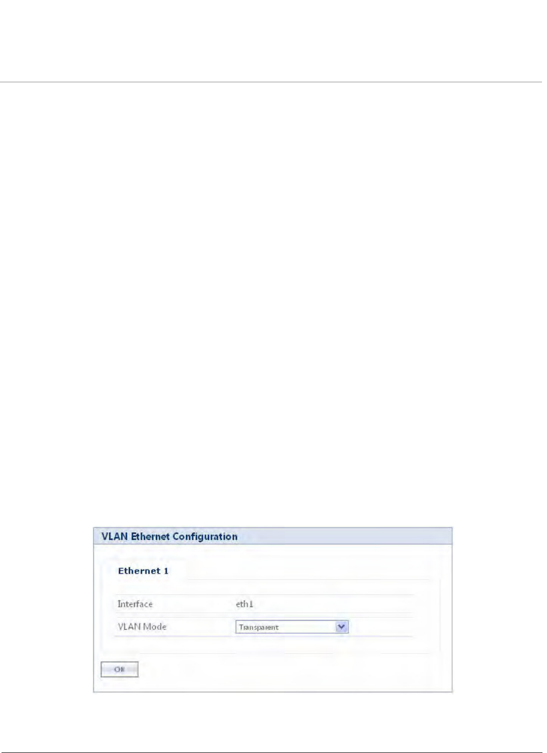
Advanced Configuration
Tsunami QB-8100 Series (100 Mbps/5 Mbps Models) Installation and Management Guide 98
1. System-related parameters: These parameters are applicable to the whole device. The following parameters are the
System-related VLAN parameters.
a. VLAN Status: Selecting the VLAN Status checkbox enables the VLAN Status on the device. To update all VLAN
related parameters, VLAN status should be enabled.
NOTE: By default, the VLAN status is disabled.
b. Management VLAN ID: This parameter is used to configure the Management VLAN ID. This option is available
when Management VLAN ID is configured. The management stations must tag the management frames sent to
the device with the management VLAN ID specified in the device. The device will tag all the management frames
from the device with the specified management VLAN and priority.
NOTES:
•If the Management VLAN ID is -1, only untagged frames can access the device.
•Before setting the Management VLAN ID from 1 to 4094, make sure that the management platform or host is a
member of the same VLAN; or else, your access to the device will be lost.
c. Management VLAN Priority: This parameter is used to set IEEE 802.1p priority for the frames. The priority value
ranges from 0 to 7. By default, it is set to 0 (zero).
2. Interface-related VLAN parameters: The device supports configuring VLAN modes for Ethernet interface. The
wireless interface is always in Transparent Mode.
4.7.2 VLAN Modes
4.7.2.1 Transparent Mode
Transparent Mode is available for the Ethernet and Wireless interfaces for both End Point A and End Point B. It is equivalent to
NO VLAN support and is the default mode. It is used to connect VLAN aware / unaware networks. An interface in
transparent mode forwards both tagged and untagged frames.
To configure the VLAN Transparent Mode
1. Click ADVANCED CONFIGURATION > VLAN > Ethernet. The VLAN Ethernet Configuration window appears as
shown below.
Figure 4-43 VLAN Operation in Transparent Mode
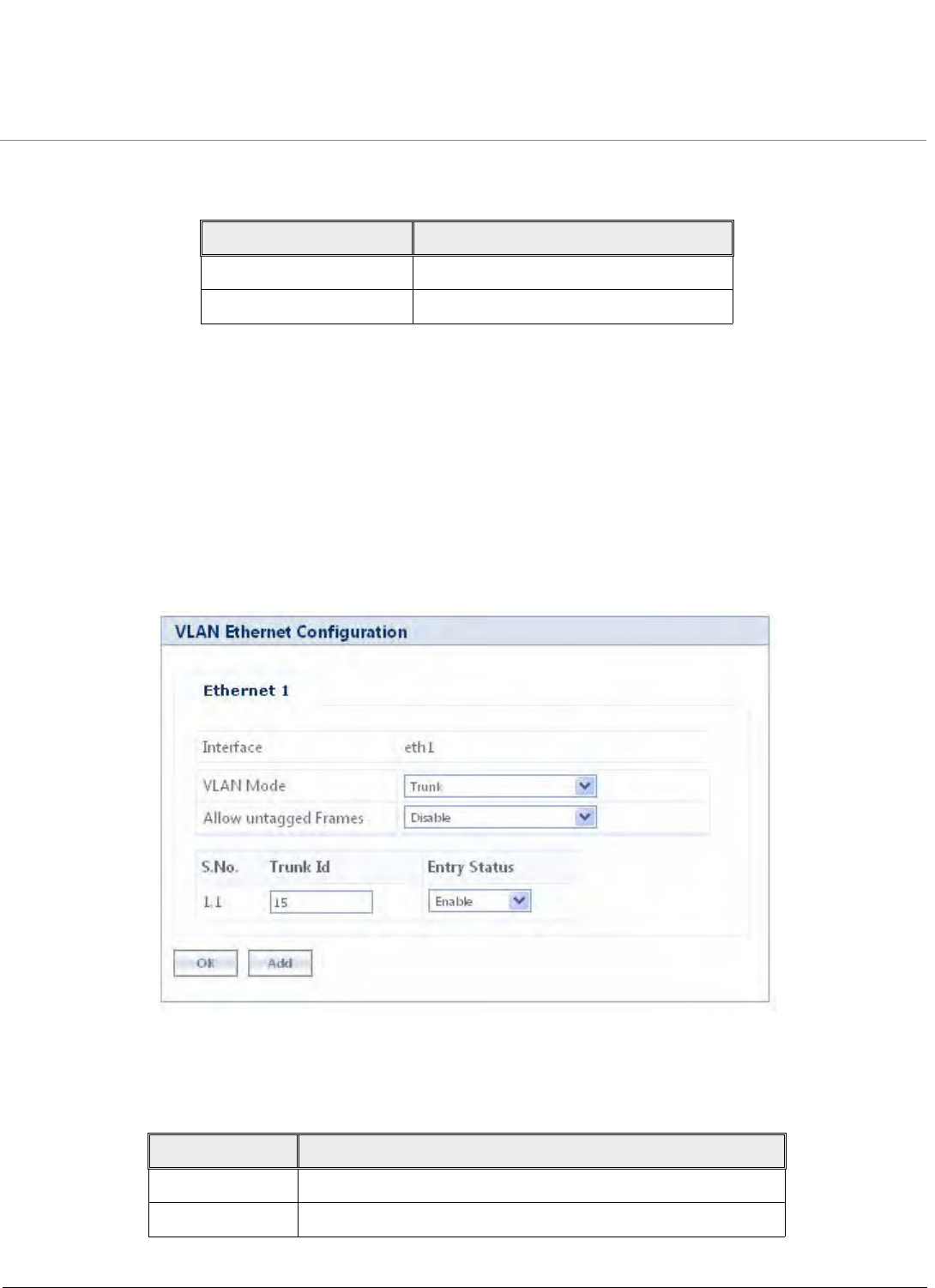
Advanced Configuration
Tsunami QB-8100 Series (100 Mbps/5 Mbps Models) Installation and Management Guide 99
2. Enter the parameters listed in the following table.
3. Click OK.
Click COMMIT for the changes to take effect. Once the transparent mode is set, both tagged and untagged frames are
received on the interface.
NOTE: Wireless Interface of the device will always be in transparent mode. There is no support provided to edit the
wireless interface VLAN parameters.
4.7.2.2 Trunk Mode
Trunk mode is configurable on both the ethernet interfaces of End Point A and End Point B. It is mainly used to connect VLAN
aware networks. When an interface is in Trunk mode, it forwards only those tagged frames whose VLAN ID matches with a
VLAN ID present in trunk table. All other frames will be dropped.
Figure 4-44 VLAN operation in Trunk Mode
To enable Trunk mode, click ADVANCED CONFIGURATION > VLAN > Ethernet and enter the settings as described in the
following table:
Parameters Description
Interface Displays the name of the interface.
VLAN Mode Select the VLAN mode as Transparent.
Parameter Description
Interface Displays the name of the interface.
VLAN Mode Select the VLAN Mode as Trunk.
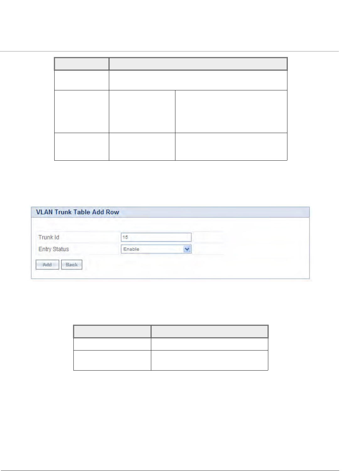
Advanced Configuration
Tsunami QB-8100 Series (100 Mbps/5 Mbps Models) Installation and Management Guide 100
Adding New Trunk Table Entries
To add new table entries
1. Click Add in the VLAN Ethernet Configuration screen. The VLAN Trunk Table Add Row page appears.
Figure 4-45 VLAN Trunk Table Add Row
2. Enter the parameters as described in the following table.
3. Click Add.
4. Click COMMIT for the changes to take effect.
NOTE: Up to 256 VLAN IDs can be configured on the Ethernet interfaces of End Point A and up to16 VLAN IDs can be
configured on the Ethernet interfaces of End Point B.
4.7.2.3 Access Mode
Access mode is available only on the Ethernet interface of End Point B. This mode is used to connect VLAN aware networks
with VLAN unaware networks. In access mode, Tagged frames with specified Access Vlan ID going out of the device through
the Ethernet interface are untagged and forwarded. The untagged frames coming into the device through the Ethernet
interface are tagged with specified Access Vlan ID and Access Vlan priority and forwarded.
Allow Untagged
Frames
Select Enable or Disable for this option.
Enable If this option is selected, an interface in
trunk mode forwards both tagged
frames whose VLAN ID matches with
one of the VLAN IDs of the trunk table
and untagged frames.
Disable If this option is selected, an interface in
trunk mode forwards only tagged
frames and drops untagged frames.
Field Description
Trunk Id Enter the value of the trunk VLAN Id.
Entry Status Enable or disable the status of the trunk
table entry.
Parameter Description
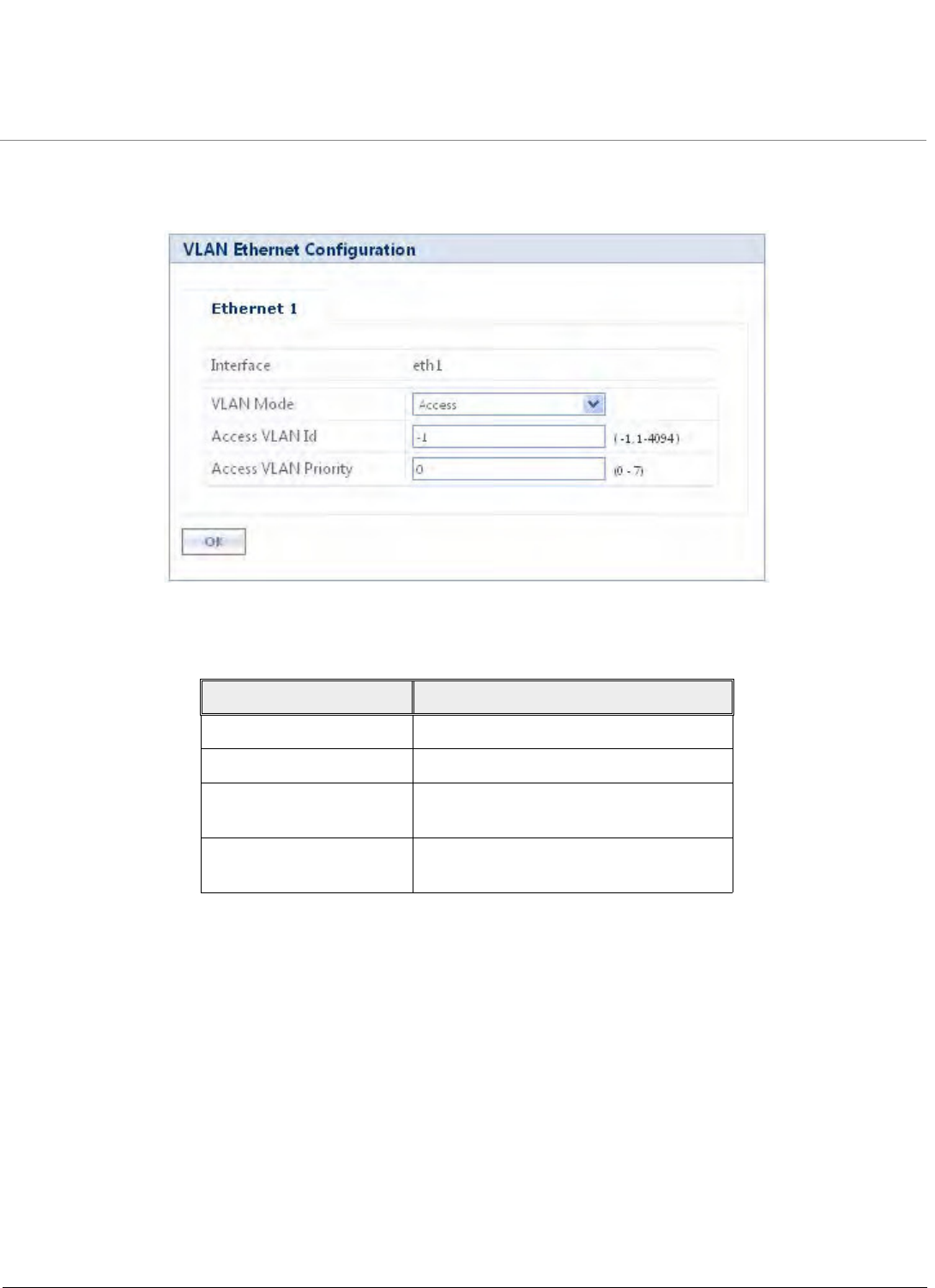
Advanced Configuration
Tsunami QB-8100 Series (100 Mbps/5 Mbps Models) Installation and Management Guide 101
To configure the Access Mode in the VLAN network
1. Click ADVANCED CONFIGURATION > VLAN > Ethernet. The VLAN Ethernet Configuration screen appears.
Figure 4-46 VLAN operation in Access Mode
2. Enter the parameters as described in the following table.
3. Click OK.
4. Click COMMIT for the changes to take effect.
4.8 Filtering Configuration (Bridge Only)
Filters are useful for preventing bridging of selected protocol traffic from one segment of a network to other segments (or
subnets). This feature can be used both to increase the amount of bandwidth available on the network and to increase
network security.
The Packet Filtering features help in controlling the amount of traffic exchanged between the wired and wireless networks.
Filtering features are available only in bridge mode operations. Using the filtering processes, you can restrict any unauthorized
packets from accessing the network.
Following are various filtering types supported by QB-8100:
•Ethernet Protocol Filter
•Static MAC Address Filter
Parameter Description
Interface Displays the name of the interface.
VLAN Mode Select the VLAN mode as Access.
Access VLAN Id The Access VLAN Id values range from 1
to 4094. The default value is -1.
Access VLAN Priority The Access VLAN priority values range
from 0 to 7. The default priority is 0.
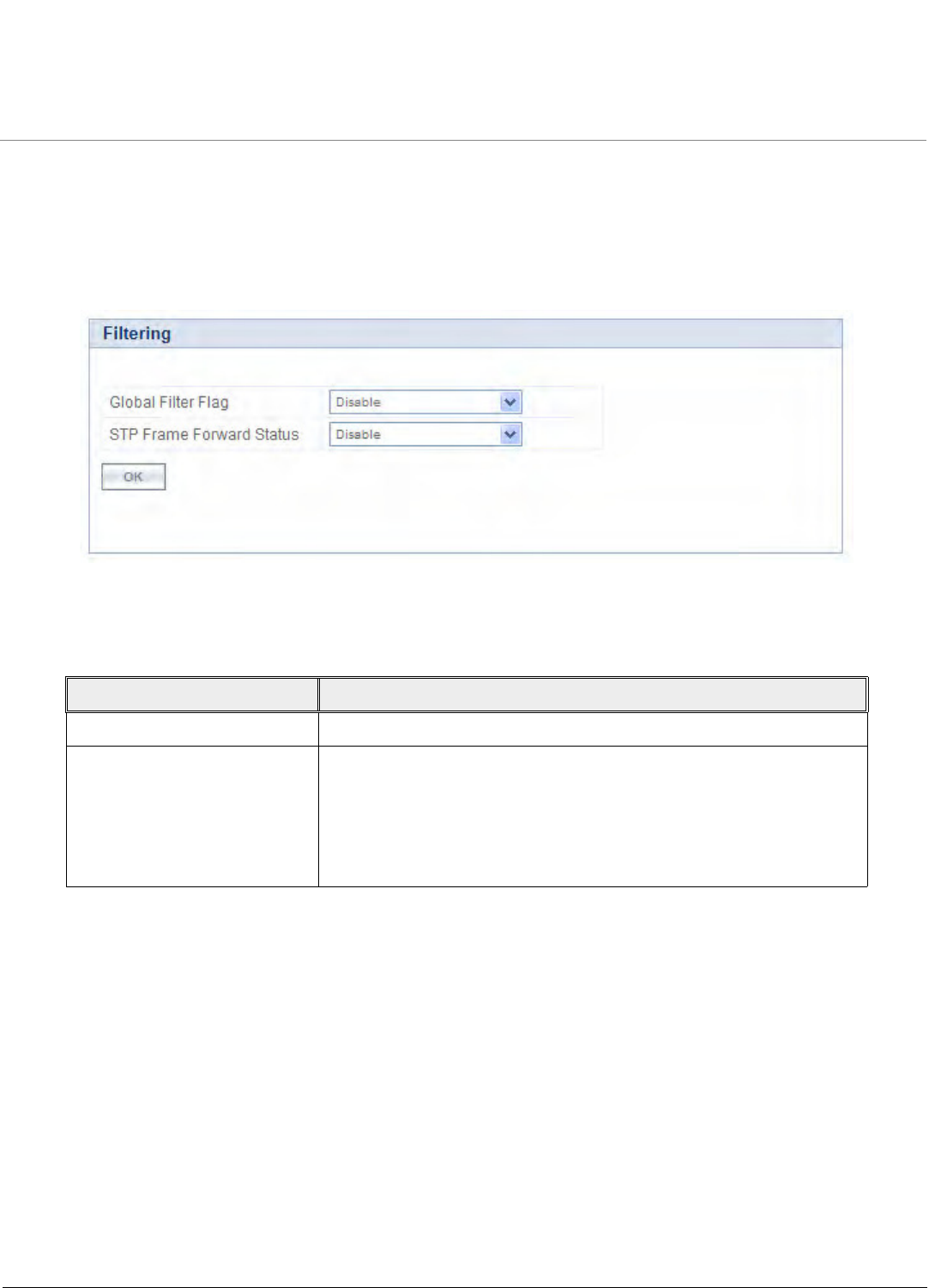
Advanced Configuration
Tsunami QB-8100 Series (100 Mbps/5 Mbps Models) Installation and Management Guide 102
•Advanced Filter
•TCP/UDP Port Filter
•Storm Threshold Filter
To configure the filtering mechanism
1. Click ADVANCED CONFIGURATION > Filtering. The Filtering screen appears.
Figure 4-47 Filtering
2. Enter the appropriate parameters in the Filtering screen. See the following table that lists all the parameters and their
descriptions.
3. Click OK.
NOTE:
• The filtering process is activated only when the Global Filter Flag is selected as Enable.
•Click COMMIT for the changes to take effect in the device.
4.8.1 Ethernet Protocol Filter
The Ethernet Protocol Filter blocks or forwards packets based on the Ethernet protocols supported on the device. The filtering
takes effect only when the Global Flag is enabled.
The packets are forwarded or dropped depending on their Entry status, Filter status and Filtering Type.
To co n figure Ethernet Protocol Filtering,
Parameter Description
Global Filter Flag This parameter is used to enable or disable complete filtering operations.
STP Frame Forward Status By accepting the STP frames, any loops that occurs within a network can
be avoided.
Enable: When this option is selected, the STP frames in the system are
bridged.
Disable: When this option is selected, the STP frames encountered in a
network are terminated at bridge.
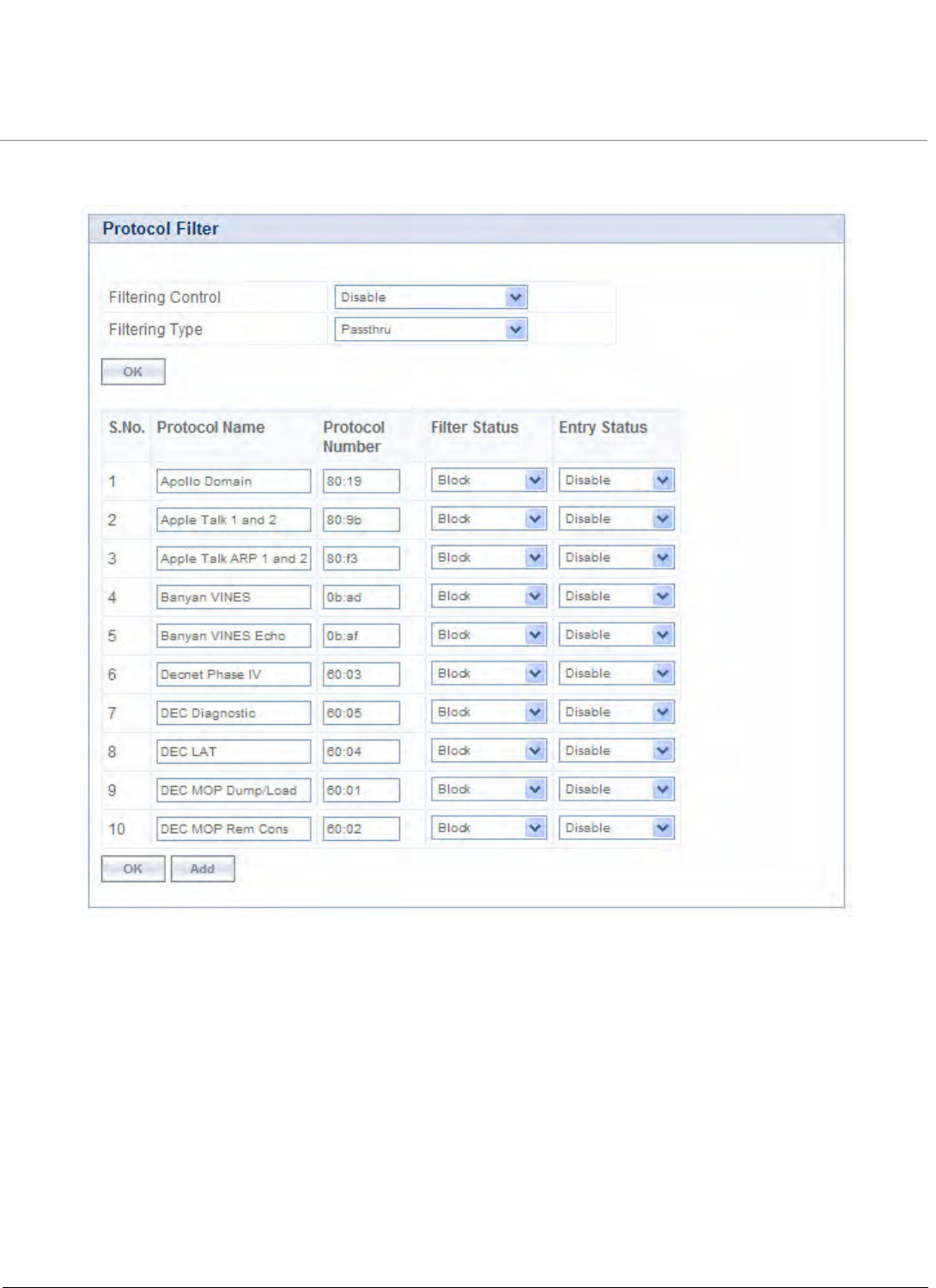
Advanced Configuration
Tsunami QB-8100 Series (100 Mbps/5 Mbps Models) Installation and Management Guide 103
1. Click ADVANCED CONFIGURATION > Filtering > Ethernet Protocol Filtering. The Protocol Filter screen is
displayed as shown below.
Figure 4-48 Protocol Filter

Advanced Configuration
Tsunami QB-8100 Series (100 Mbps/5 Mbps Models) Installation and Management Guide 104
2. Enter the appropriate parameters in the Protocol Filter screen. See the following table that lists the parameters and
their descriptions.
3. A few frequently used filters are listed in the Ethernet Protocol Filter Table.
4. For adding new entries to the Protocol filter Table:
a. Click Add to display the Protocol Filters Add Row page as shown in the following figure.
Parameter Description
Filtering Control This parameter is used to configure the interface on which filtering has
to be applied. By default, it is disabled. It can be configured as:
•Ethernet: Packets are examined on the receive path of the
Ethernet interface.
•Wireless: Packets are examined at the Wireless interface.
•All Interfaces: Packets are examined at both Ethernet and
wireless interfaces.
•Disable: The protocol filtering process is disabled.
Filtering Type The Filtering Type specifies the action to be taken on the packet
whose protocol/ether type is not registered in the protocol filter table
or whose Entry Status is in Disable state. By default, it is set to
Passthru.
Block: The protocols with entry status Disable or the protocols which
do not exist in the protocol filtering table are blocked.
Passthru: The protocols with entry status Disable or the protocols
which do not exist in the protocol filtering table are allowed through
the interface.
NOTE: Click COMMIT for the changes to take effect in the device.
Ethernet Protocol Filter Table
Protocol Name Specifies the name of the Ethernet Protocol.
Protocol Number Specifies the value of the Ethernet Protocol. The value is of 4 digit Hex
format.
Filter Status This parameter allows configuring the Filter Status as either Block or
Passthru. The default is Block. Selection of the Filter Status takes
effect only if the Entry Status is Enabled.
When this filter status is set to Passthru and entry status is Enable, all
packets whose protocol matches with the given protocol number are
forwarded on the selected interface.
When this filter status is set to Block and entry status is Enable, all
packets whose protocol matches with the given protocol number are
dropped on selected interface.
Entry Status Set the Entry Status as Enable/Disable/Delete.
NOTE: Click COMMIT for the changes to take effect in the device.
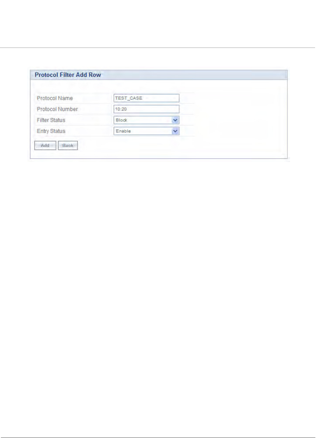
Advanced Configuration
Tsunami QB-8100 Series (100 Mbps/5 Mbps Models) Installation and Management Guide 105
b. Enter the details as described in the preceding table and click Add.
Figure 4-49 Protocol Filter Add Row
NOTE:
•By default, the system generates 19 entries. You can Enable or Disable the default entries, but the Delete option
is not applicable for all the default 19 entries.
•The added entry in the table can be enabled, disabled, or deleted based on user requirement.
•Max Entries supported in Ethernet Protocol Filter Table are 64.
4.8.2 Static MAC Address Filter
4.8.2.1 Overview
The Static MAC Address filter optimizes the performance of a wireless and wired network. When this feature is configured,
the device can block traffic between wired and wireless network based on MAC address.
The filter limits the data traffic between two specific devices (or between groups of devices based on MAC addresses and
masks) through the unit’s wireless interface. For example, a server on the network, which should not allow wireless clients to
communicate, can be set up with a static MAC filter to block traffic between these devices. The Static MAC Filter Table
performs bi-directional filtering.
Each MAC address or mask consists of 12 hexadecimal digits (0-9 and A-F) that correspond to a 48-bit identifier. Each
hexadecimal digit represents 4 bits (0 or 1).
Taken together, a MAC address/mask pair specifies an address or a range of MAC addresses that the device looks for when
examining packets. The device performs bitwise “AND” operation between the MAC address and the mask at the bit level. A
mask of 00:00:00:00:00:00 corresponds to all MAC addresses, and a mask of FF:FF:FF:FF:FF:FF applies only to the specified
MAC address.
For example, if the MAC address is 00:20:A6:12:54:C3 and the mask is FF:FF:FF:00:00:00, the device examines the source
and destination addresses of each packet looking for any MAC address starting with 00:20:A6. If the mask is FF:FF:FF:FF:FF:FF,
the device looks only for the specific MAC address (in this case, 00:20:A6:12:54:C3).
When creating a filter, the user can configure the Wired parameters only, the Wireless parameters only, or both sets of
parameters.
•To prevent all traffic from a specific wired MAC address from being forwarded to the wireless network, configure only
the Wired MAC address and Wired mask (leave the Wireless MAC and Wireless mask set to all zeros).
•To prevent all traffic from a specific wireless MAC address from being forwarded to the wired network, configure only
the Wireless MAC and Wireless mask (leave the Wired MAC address and Wired mask set to all zeros).

Advanced Configuration
Tsunami QB-8100 Series (100 Mbps/5 Mbps Models) Installation and Management Guide 106
•To block traffic between a specific wired MAC address and a specific wireless MAC address, configure all four
parameters.
4.8.2.2 Static MAC Filter Examples
Consider a network that contains a wired server and three wireless clients. The MAC addresses for each unit are as follows:
•Wired Server: 00:40:F4:1C:DB:6A
•Wireless Client 1: 00:02:2D:51:94:E4
•Wireless Client 2: 00:02:2D:51:32:12
•Wireless Client 3: 00:20:A6:12:4E:38
Prevent Two Specific Devices from Communicating
Configure the following settings to prevent the Wired Server and Wireless Client 1 from communicating:
•Wired MAC Address: 00:40:F4:1C:DB:6A
•Wired Mask: FF:FF:FF:FF:FF:FF
•Wireless MAC Address: 00:02:2D:51:94:E4
•Wireless Mask: FF:FF:FF:FF:FF:FF
Result: Traffic between the Wired Server and Wireless Client 1 is blocked. Wireless Clients 2 and 3 still can communicate with
the Wired Server.
Prevent Multiple Wireless Devices From Communicating With a Single Wired Device
Configure the following settings to prevent Wireless Clients 1 and 2 from communicating with the Wired Server:
•Wired MAC Address: 00:40:F4:1C:DB:6A
•Wired Mask: FF:FF:FF:FF:FF:FF
•Wireless MAC Address: 00:02:2D:51:94:E4
•Wireless Mask: FF:FF:FF:00:00:00
Result: When a logical “AND” is performed on the Wireless MAC Address and Wireless Mask, the result corresponds to any
MAC address beginning with the 00:20:2D prefix. Since Wireless Client 1 and Wireless Client 2 share the same prefix
(00:02:2D), traffic between the Wired Server and Wireless Clients 1 and 2 is blocked. Wireless Client 3 can still communicate
with the Wired Server since it has a different prefix (00:20:A6).
4.8.2.3 Prevent All Wireless Devices From Communicating With a Single Wired Device
Configure the following settings to prevent Wired Server from communicating with all three Wireless Clients:
•Wired MAC Address: 00:40:F4:1C:DB:6A
•Wired Mask: FF:FF:FF:FF:FF:FF
•Wireless MAC Address: 00:00:00:00:00:00
•Wireless Mask: 00:00:00:00:00:00
Result: The unit blocks all traffic between the Wired Server and all wireless clients.
4.8.2.4 Prevent a Wireless Device from Communicating with the Wired Network
Configure the following settings to prevent Wireless Client 3 from communicating with any device on the Ethernet:
•Wired MAC Address: 00:00:00:00:00:00
•Wired Mask: 00:00:00:00:00:00
•Wireless MAC Address: 00:20:A6:12:4E:38
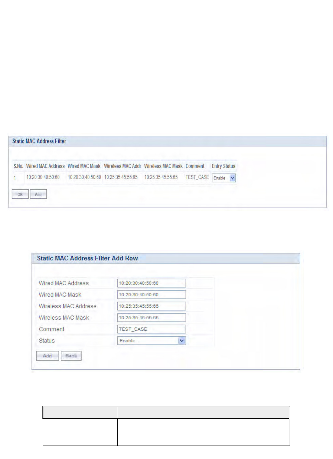
Advanced Configuration
Tsunami QB-8100 Series (100 Mbps/5 Mbps Models) Installation and Management Guide 107
•Wireless Mask: FF:FF:FF:FF:FF:FF
Result: The unit blocks all traffic between Wireless Client 3 and the Ethernet network.
4.8.2.5 Static MAC Address Filter Configuration
To configuring Static MAC Filter
1. Click ADVANCED CONFIGURATION > Filtering > Static Mac Address Filter. The Static MAC Address Filter
screen is displayed as shown below.
Figure 4-50 Static MAC Address Filter
2. Click Add. The Static MAC Address Filter Add Row screen appears.
Figure 4-51 Creating a new Static MAC Address Filter
3. Enter the parameters listed in the following table.
Parameter Description
Wired MAC Address Specifies the MAC address of the device on the wired network
that is restricted from communicating with a device in the
wireless network.

Advanced Configuration
Tsunami QB-8100 Series (100 Mbps/5 Mbps Models) Installation and Management Guide 108
NOTE: The Static MAC Address Filter table supports up to 200 entries.
4. Click Add to add a new entry to the Static MAC Address Filter table.
5. Click Commit so that the filter gets applied on the network.
NOTE:
•The Wired MAC address and the Wireless MAC address should be a unicast MAC address.
•MAC Address/Mask includes 12 hexadecimal digits (each hexadecimal equals to 4 bits containing 0 or 1) which are
equivalent to 48 bit identifier.
4.8.3 Advanced Filter
In Advanced Filtering, IP protocols which are frequently used or transmitted through the network are filtered.
To view the advanced filtering
1. Click ADVANCED CONFIGURATION > Filtering > Advanced Filtering. The Advanced Filtering screen is displayed
as shown below.
Wired MAC Mask Specifies the range of MAC address to which this filter is to be
applied.
Wireless MAC address Specifies the MAC address of the device on the wireless
network that is restricted from communicating with a device in
the wired network.
Wireless MAC Mask Specifies the range of MAC address to which this filter is to be
applied.
Comment Specifies the comment associated with Static MAC Filter table
entry.
Status Specifies the status of the newly created filter.
Parameter Description
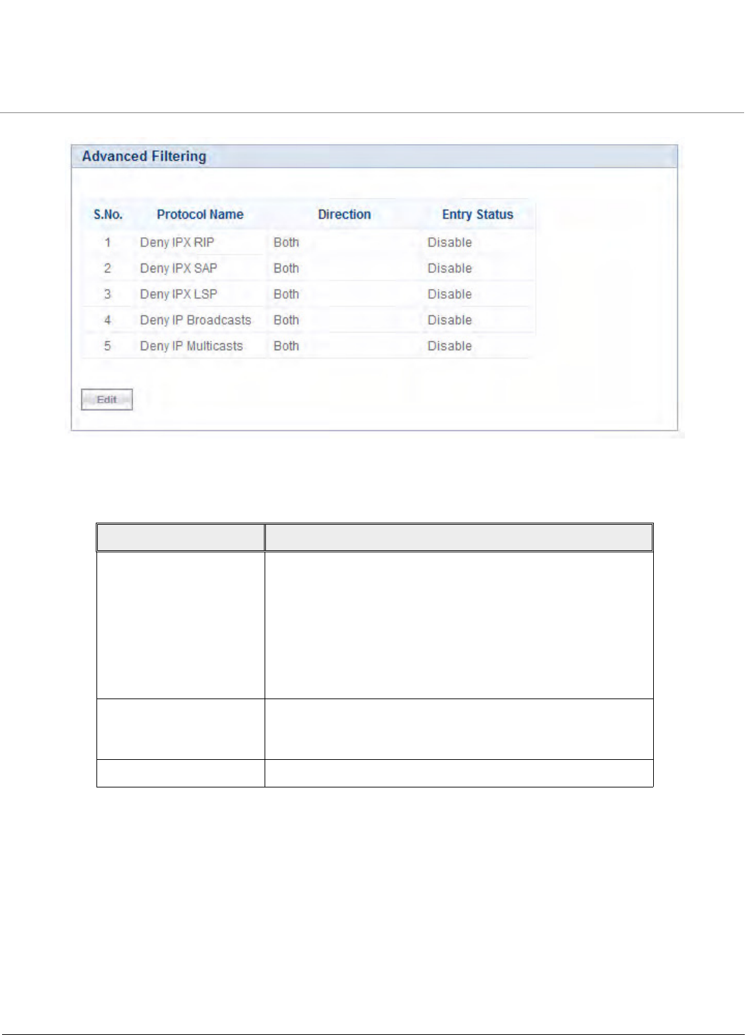
Advanced Configuration
Tsunami QB-8100 Series (100 Mbps/5 Mbps Models) Installation and Management Guide 109
Figure 4-52 Advanced Filtering
2. The following table describes the parameters present in the Advanced Filtering table.
NOTE:
•The Advanced Filtering table contains maximum 5 entries.
•New entries cannot be added and existing entries cannot be deleted from the Advanced Filtering table.
4.8.3.1 Editing Table Entries
1. Click Edit to modify the existing table details. The Advanced Filtering - Edit Entries page appears.
Parameter Description
Name This parameter specifies the protocol name. The following
filters are supported in Advanced Filtering:
•Deny IPX RIP
•Deny IPX SAP
•Deny IPX LSP
•Deny IP Broadcasts
•Deny IP Multicasts
Direction This parameter specifies the direction of an individual entry in
the Advanced Filter table. The direction can be Ethernet to
Wireless, Wireless to Ethernet, or both.
Entry Status This parameter specifies the status of the individual entry.
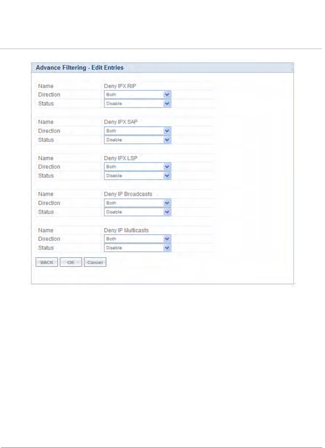
Advanced Configuration
Tsunami QB-8100 Series (100 Mbps/5 Mbps Models) Installation and Management Guide 110
Figure 4-53 Advance Filtering- Edit Entries
1. After making the desired modifications, click OK to update the table.
2. Click Back to navigate to the previous page. Click Cancel to retain the previous entries.
NOTE: Click COMMIT for the changes to take effect in the device.
4.8.4 TCP/UDP Port Filter
Port-based filtering controls the user access to network services by selectively blocking TCP/UDP protocols through the device.
A user can specify a Protocol Name, Port Number, Port Type (TCP, UDP, or TCP/UDP), and filtering interfaces (only Wireless,
only Ethernet or all Interfaces). These parameters can be used to block access to services, such as Telnet and FTP and the
traffic, such as NETBIOS and HTTP.
To configure the TCP/UDP Port filtering technique
1. Click ADVANCED CONFIGURATION > Filtering > TCP/UDP Port Filter. The TCP/UDP Port Filter screen is displayed
as shown below. Create a new protocol by clicking Add or make use of the existing protocols.
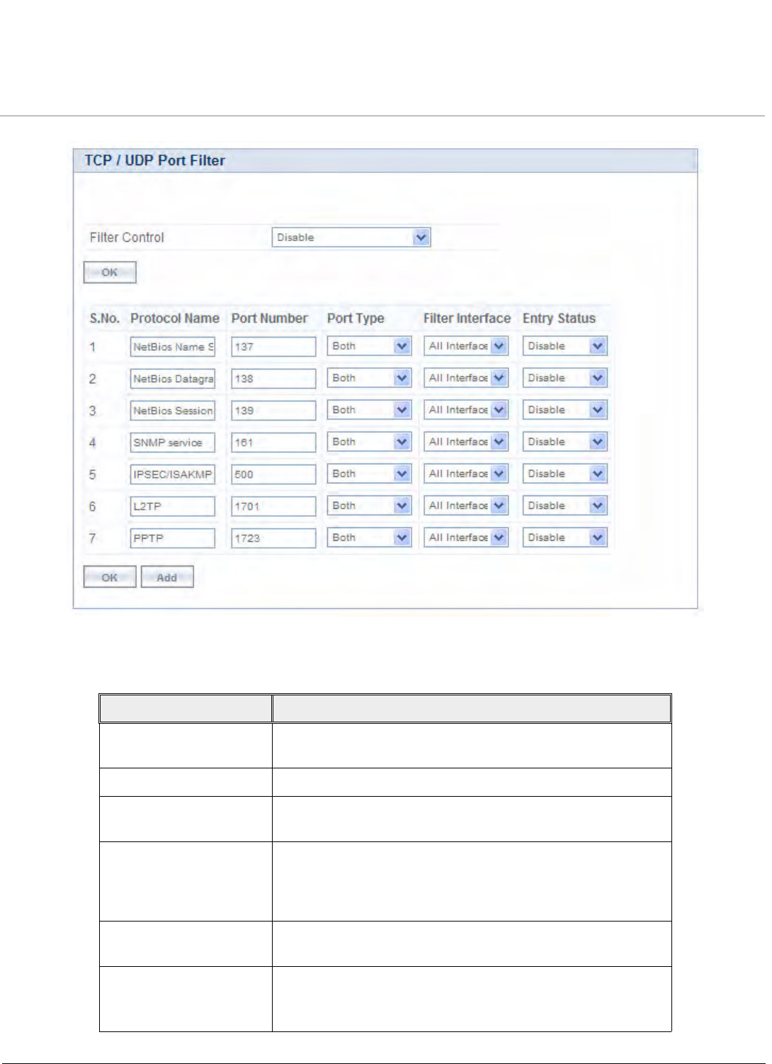
Advanced Configuration
Tsunami QB-8100 Series (100 Mbps/5 Mbps Models) Installation and Management Guide 111
Figure 4-54 TCP/UDP Port Filter
2. Enter the appropriate parameters. See the following table that lists the parameters and their descriptions.
Parameter Description
Filter Control This parameter is used to enable the TCP/UDP filter. By default,
Disable is selected.
Protocol Name This parameter specifies the TCP/UDP protocol filter name.
Port Number This parameter specifies the TCP/UDP port number. It accepts
the values within the range 0-65535.
Port Type This parameter specifies the type of the port. The various
options for the Port Type are TCP, UDP and Both. By default,
Port Type is Both for the default entries and TCP for the newly
added entries.
Filter Interface This parameter is used to configure the interface type. Options
for filter interface are Ethernet, Wireless, and All Interfaces.
Entry Status This parameter indicates the status of TCP/UDP filter entry.
Enable: The device filters the TCP/UDP protocols
Disable: The device allows all the TCP/UDP protocols.
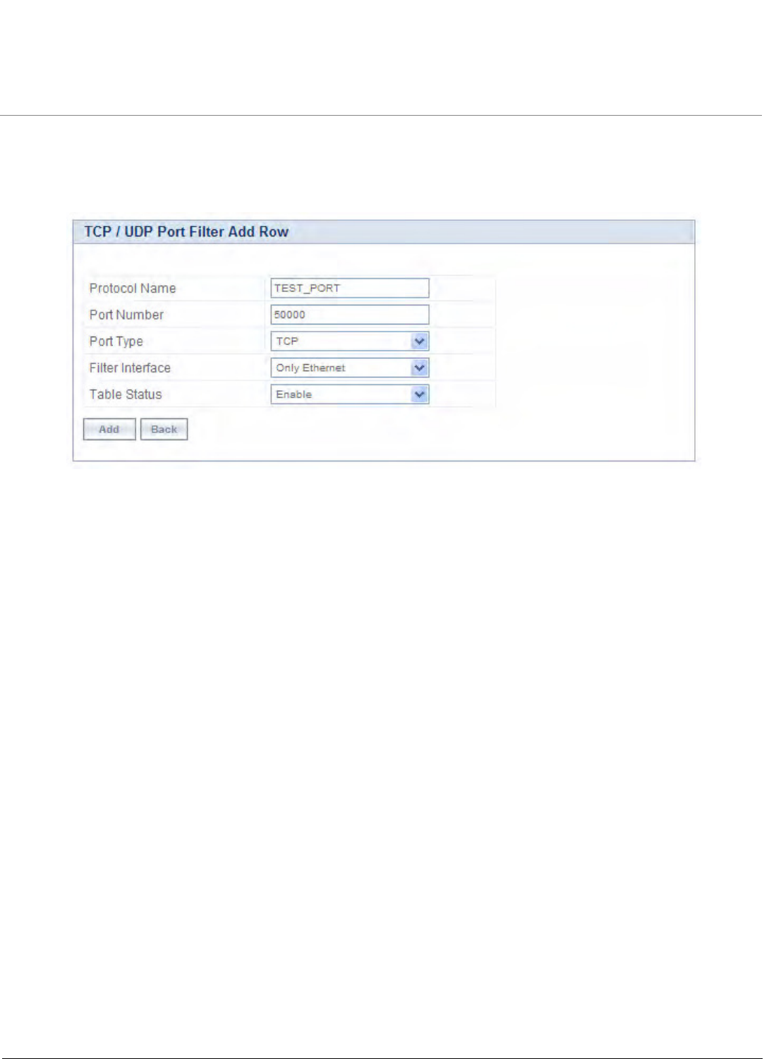
Advanced Configuration
Tsunami QB-8100 Series (100 Mbps/5 Mbps Models) Installation and Management Guide 112
4.8.4.1 Adding TCP/UDP Port Table Entries
To add TCP/UDP Port Table entries
1. Click Add to create a new TCP/UDP port filter. The TCP/UDP Port Filter Add Row page is displayed as shown below.
Figure 4-55 TCP/UDP Port Filter Add Row
2. Enter the details and click Add to update the entry in the TCP/UDP table.
NOTE:
•The TCP/UDP filtering operation is allowed only when the Global flag and Filter Control options are selected as
Enable
•Maximum 64 entries can be added to the table.
•Click COMMIT for the changes to take effect in the device.
4.8.5 Storm Threshold Filter
The Storm Threshold Filter restricts the excessive inbound multicast or broadcast traffic on layer two interfaces. This protects
against broadcast storms resulting from spanning tree misconfiguration. A broadcast/multicast filtering mechanism needs to
be enabled so that a large percentage of the wireless link remains available to the connected mobile terminals.
To configure Storm Threshold Filter,
1. Click ADVANCED CONFIGURATION > Filtering > Storm Threshold Filter. The Storm Threshold Filter screen appears as
shown below:

Advanced Configuration
Tsunami QB-8100 Series (100 Mbps/5 Mbps Models) Installation and Management Guide 113
Figure 4-56 Storm Threshold Filter
This table contains information about the threshold values per second of the multicast and broadcast packets that can be
processed for the interface(s) present in the device.
2. Select the appropriate parameters. See the following table that lists the parameters and their descriptions.
3. Click OK.
4.8.6 WORP Intra Cell Blocking (End Point A Only, Bridge Mode only)
Since the QB-8100 units operate in a point-to-point network mode, the Intra Cell Blocking feature has no significance for QB
units. This feature is disabled by default and configuring these parameters is not necessary.
Parameter Description
Interface This parameter is used to configure the type of interface in which
filtering has to be applied. The Storm Threshold filter can be used
to filter the traffic on two types of interfaces such as: Ethernet or
Wireless. By default, Storm Threshold filtering is disabled on both
Ethernet and Wireless interfaces.
Multicast Threshold This parameter is used to configure the threshold value of the
multicast packets to be processed for the Ethernet or Wireless
interface. Packets more than threshold value are dropped. If
threshold value for multicast packets is set to '0', filtering is
disabled. The default Multicast Threshold value is 0 per second.
Broadcast Threshold This parameter is used to configure the threshold value of the
broadcast packets to be processed for the Ethernet or Wireless
interface. Packets more than threshold value are dropped. If
threshold value for broadcast packets is set to '0', filtering is
disabled. The default Broadcast Threshold value is 0 per
second.
Advanced Configuration
Tsunami QB-8100 Series (100 Mbps/5 Mbps Models) Installation and Management Guide 114
4.9 DHCP Configuration
Dynamic Host Configuration Protocol (DHCP) is a network protocol that enables a server to assign an IP address to a device
from a defined range of IP addresses configured for a given network. It allows you to distribute IP addresses from a central
point to various hosts and simplifies the process of configuring the IP addresses to individual hosts.
Figure 4-57 DHCP
4.9.1 DHCP server
DHCP automatically allocates network addresses and also delivers configuration parameters dynamically to the clients from
the DHCP server. When DHCP server is enabled, it allows allocation of IP addresses to clients connected to the End Point A or
End Point B.
The DHCP Server lets the End Point A or End Point B respond to DHCP requests with the following information:
•Host IP address
•Gateway IP address
•Subnet Mask
•Lease Time
•DNS Primary Server IP address
•DNS Secondary Server IP address
In Routing mode, DHCP Server can be configured for each interface separately. Unless the DHCP Server functionality is
enabled for an interface, the DHCP Server does not respond to the DHCP requests received on that interface.
NOTE: The DHCP Server functionality is available in both Routing and Bridge Modes.
To configure the DHCP server and DHCP Interface table
1. Click ADVANCED Configuration > DHCP > DHCP Server > Interfaces. The DHCP screen appears as shown below.
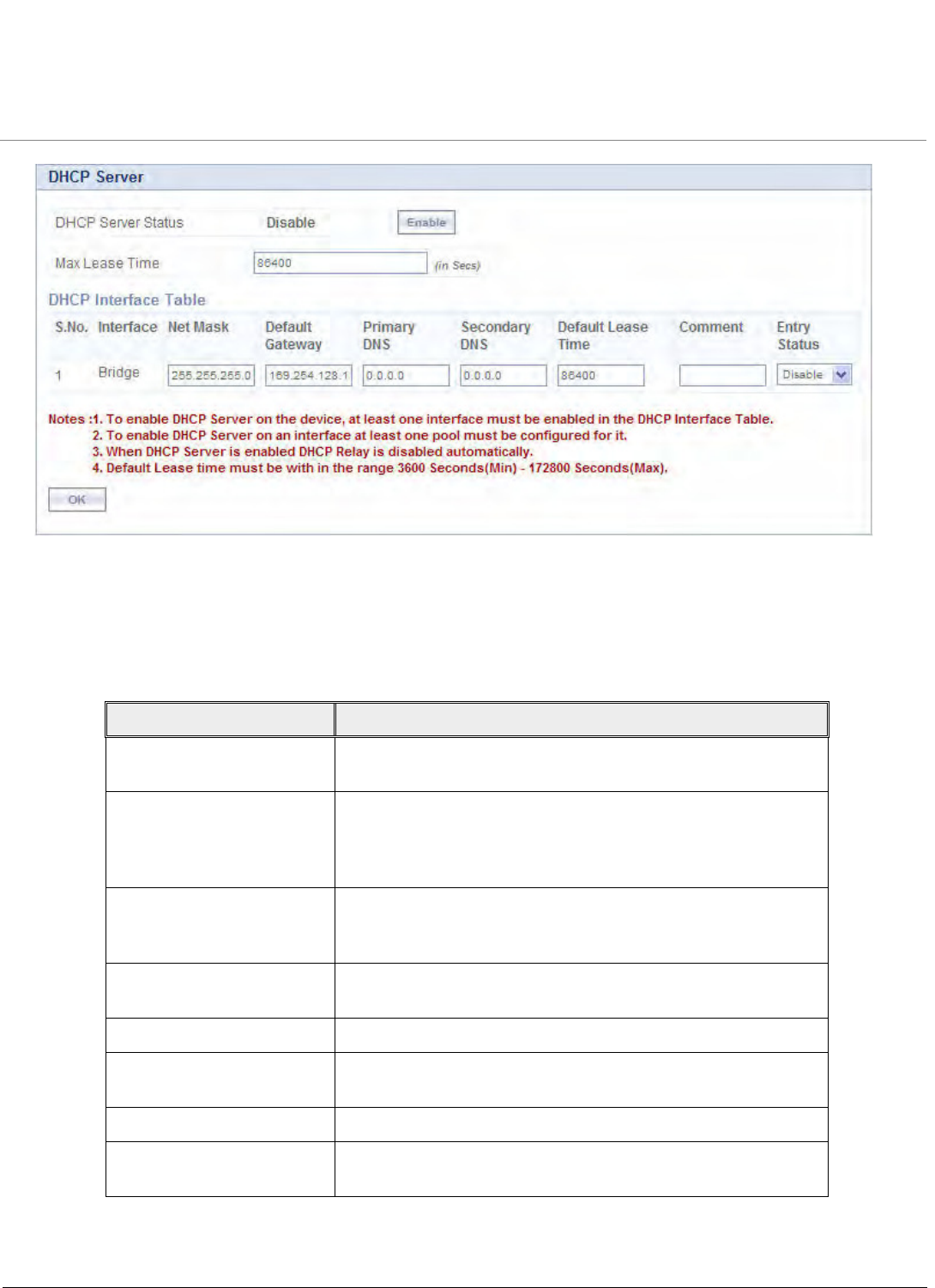
Advanced Configuration
Tsunami QB-8100 Series (100 Mbps/5 Mbps Models) Installation and Management Guide 115
Figure 4-58 DHCP
2. Enter the appropriate parameters in the DHCP Interface Table. See the following table that lists the parameters and
their descriptions.
NOTE: To enable the DHCP Server Interface, the DHCP server pool table should have at least one range configured for
that interface.
Parameter Description
Interface Type Specifies the interface for which the DHCP Server functionality
shall be configured.
Net Mask Specifies the subnet mask to be sent to the client along with the
assigned IP address. The netmask configured here should be
greater than or equal to the netmask configured on the
interface.
Default Gateway Specifies the default gateway to be sent to the client along with
assigned IP Address. Default Gateway is a node that serves as an
accessing point to another network.
Primary DNS Specifies the primary DNS (Domain Name Server) IP address to be
sent to the client.
Secondary DNS Specifies the secondary DNS IP address to be sent to the client.
Default Lease Time DHCP Server uses this option to specify the lease time it is willing
to offer to the client over that interface.
Comment Specifies a note for the device administrator.
Entry Status Used to enable or disable the DHCP server functionality over the
interface.
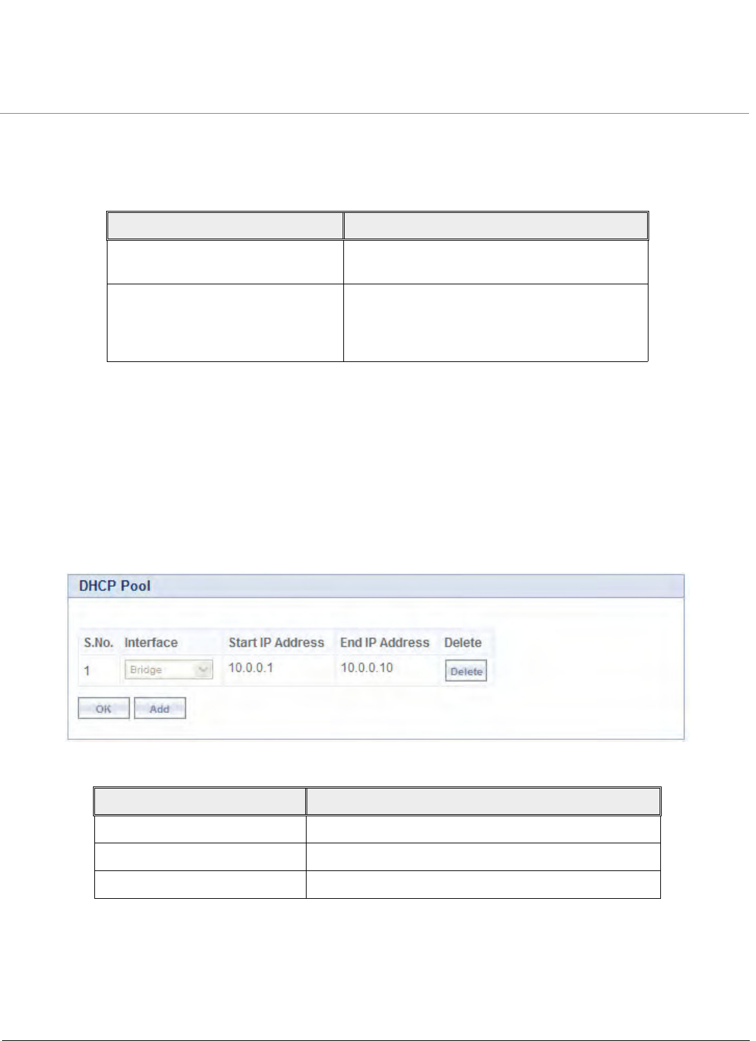
Advanced Configuration
Tsunami QB-8100 Series (100 Mbps/5 Mbps Models) Installation and Management Guide 116
3. To enable DHCP Server, select Enable for DHCP Server Status. Before enabling, in interface table there should be at
least one interface enabled on which the DHCP Server has to run and the DHCP server pool table should have at least
one entry configured for that interface.
4. In the Max Lease Time field, enter the maximum lease time.
5. Click OK.
6. To apply the configured properties of the device, click COMMIT.
NOTE: For DHCP Server to be enabled on an interface, at least one address pool must be configured for that interface.
4.9.1.1 DHCP Pool
To configure DHCP Pool
1. Click ADVANCED CONFIGURATION > DHCP > DHCP Server > Pool. The DHCP Pool screen appears as shown
below.
Figure 4-59 DHCP Pool
NOTE: Up to 5 entries per interface can be added in the IP Pool Table. A pool entry can be deleted but cannot be
edited.
4.9.1.2 Adding a New Pool Entry
To add a new Pool entry to the DHCP server
Parameter Description
DHCP Status This parameter is used to enable DHCP Server or
disable the DHCP functionality on the device.
Max Lease Time Specifies the maximum lease time for which the
DHCP client can have the IP address provided by
the Server. The value ranges from 3600-86400
seconds.
Parameter Description
Interface Specifies the interface to which the pool belongs.
Start IP Address/End IP Address Specifies the start and end IP Address of the pool.
Delete Allows the user to delete the added pool entry.
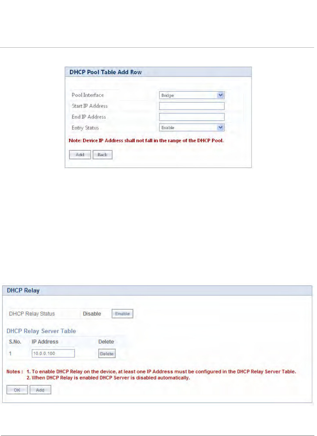
Advanced Configuration
Tsunami QB-8100 Series (100 Mbps/5 Mbps Models) Installation and Management Guide 117
1. Click Add in the DHCP Pool screen. The DHCP Pool Table Add Row screen is displayed as shown below.
Figure 4-60 DHCP Pool Table Add Row
2. After entering the details, click Add. The entry will be updated in the DHCP pool table.
3. To apply the changes, click COMMIT.
4.9.2 DHCP Relay (Routing Mode only)
The DHCP relay agent forwards DHCP requests to the given DHCP server. There must be at least one entry in the
corresponding Server IP Address table to enable the DHCP Relay Agent. A maximum of 5 servers can be configured.
NOTE: DHCP Relay Agent parameters are configurable only in Routing mode. It cannot be enabled when NAT or DHCP
Server are enabled.
To view entries in DHCP Relay Server
•Click ADVANCED CONFIGURATION > DHCP > DHCP Relay > Relay Server.
Figure 4-61 DHCP Relay
To add Relay Server Table entry
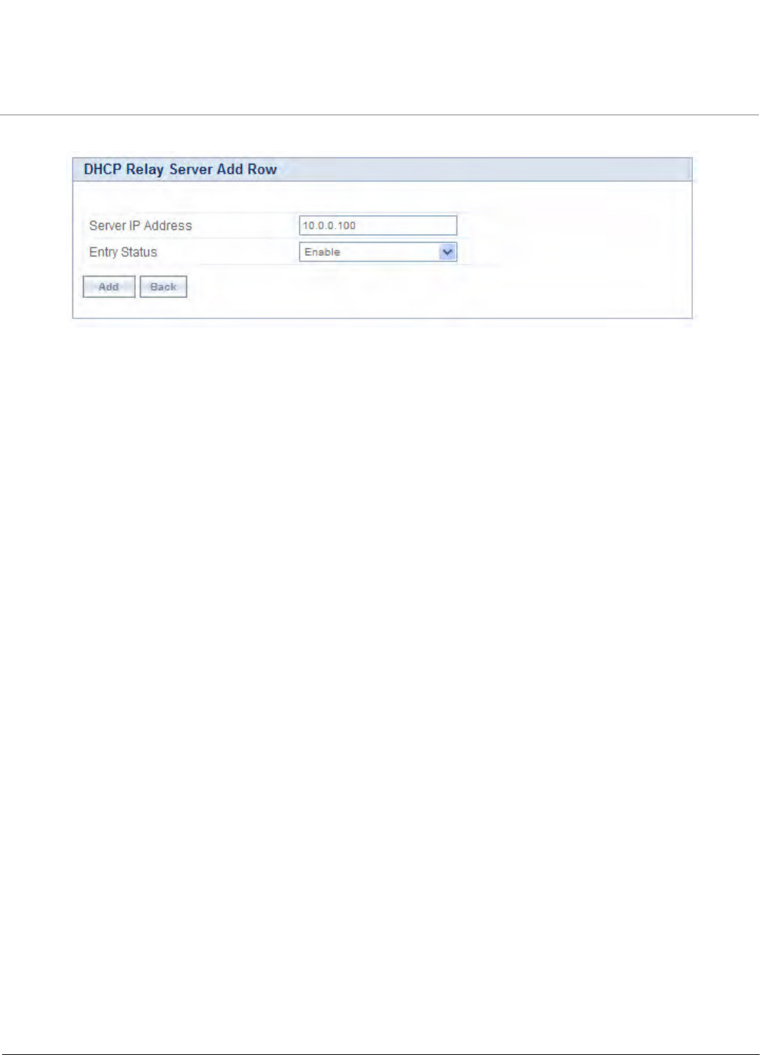
Advanced Configuration
Tsunami QB-8100 Series (100 Mbps/5 Mbps Models) Installation and Management Guide 118
1. Click Add in the DHCP Relay Server screen. The DHCP Relay Server Add Row screen is displayed as shown below.
Figure 4-62 DHCP Relay Server Add Row
2. Enter the Server IP Address and then click Add.
3. To enable DHCP Relay, click Enable for DHCP Relay Status. Before enabling, there must be at least one IP address
configured in the DHCP Relay Server Table.
4. Click OK. To apply the changes, click COMMIT.
NOTE: To enable the DHCP Relay, the NAT functionality must be disabled.
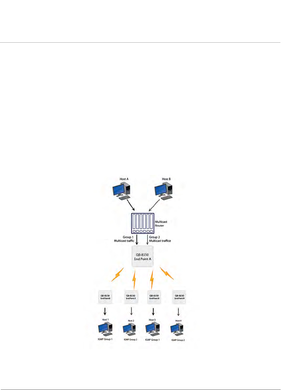
Advanced Configuration
Tsunami QB-8100 Series (100 Mbps/5 Mbps Models) Installation and Management Guide 119
4.10 IGMP Snooping (Bridge Mode only)
The Internet Group Management Protocol (IGMP) is a communication protocol used to manage the membership of
Internet Protocol multicast groups. IGMP is used by IP hosts and adjacent multicast routers to establish multicast group
memberships.
Internet Group Management Protocol (IGMP) Snooping is the process of listening to IGMP network traffic. It is a feature
that allows a layer 2 switch to “listen in” on the IGMP conversation between hosts and routers by processing the layer 3
IGMP packets sent in a multicast network.
4.10.0.1 Types of IGMP Snooping:
There are two types of IGMP Snooping.
Active IGMP Snooping:
Active IGMP Snooping listens to IGMP traffic and filters IGMP packets to reduce load on the multicast router. Joins and leaves
heading upstream to the router are filtered so that only the minimal quantity of information is sent.
Passive IGMP Snooping:
Passive IGMP Snooping simply listens to IGMP traffic and does not filter or interfere with IGMP.
Figure 4-63 IGMP Snooping Process
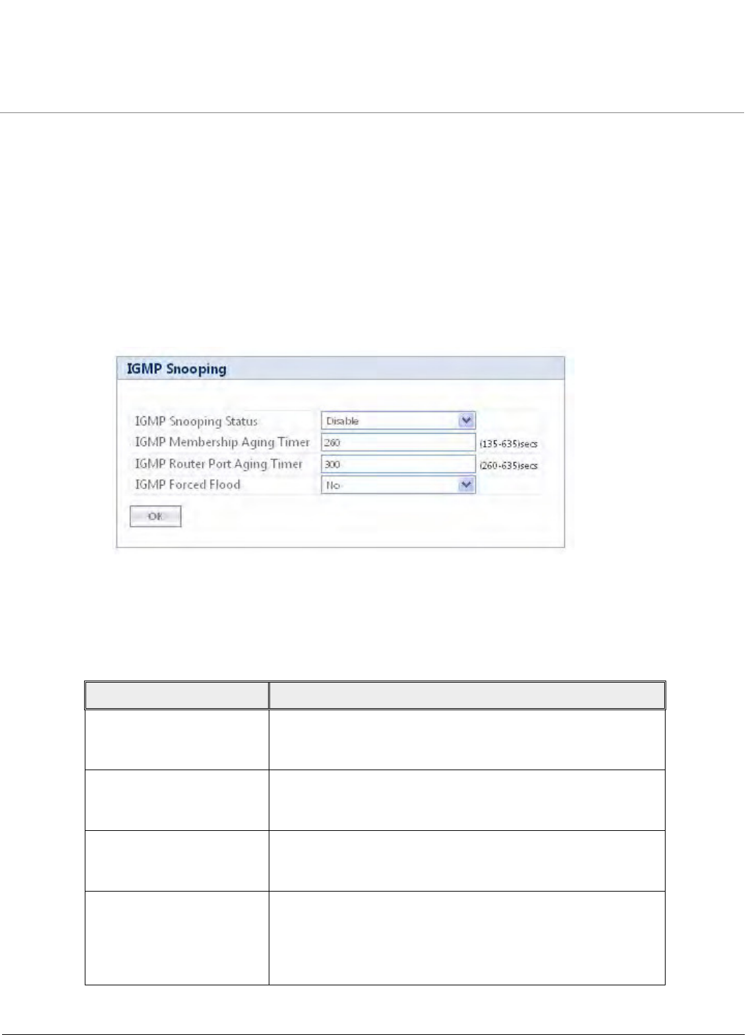
Advanced Configuration
Tsunami QB-8100 Series (100 Mbps/5 Mbps Models) Installation and Management Guide 120
NOTES:
•IGMP Snooping functionality is available both in End Point A and End Point B.
•QB 8100 supports only passive IGMP Snooping.
•IGMP versions V1,V2 and V3 are supported.
•End Point A/End Point B add maximum 64 Multicast groups in the Snooping table.
4.10.1 IGMP Snooping Configuration
To configure IGMP Snooping:
1.Click ADVANCED Configuration > IGMP Snooping. The IGMP snooping screen appears as shown below.
Figure 4-64 IGMP Snooping
2. Enter the appropriate parameters in the IGMP Snooping Table. See the following table that lists the parameters and their
descriptions.
3.Click OK. To apply the changes, click COMMIT.
Parameter Description
IGMP Snooping Status This parameter is used to Enable/Disable the IGMP Snooping
feature for the device. This feature is supported only in bridge
mode. By default, IGMP Snooping Status is disabled.
IGMP Membership
Aging Timer
This parameter represents the time after which the IGMP
multicast group age-outs or elapses. It ranges from 135 to 635
sec. The default IGMP Membership Aging Timer is 260 sec.
IGMP Router Port
Aging Timer
This parameter represents the time after which the IGMP router
port age-outs or elapses. It ranges from 260 to 635 sec. The
default IGMP Router Port Aging Timer is 300 sec.
IGMP Forced Flood If you select Yes, all the Unregistered IPv4 multicast traffic (with
destination address which does not match any of the groups
announced in earlier IGMP Membership reports) and IGMP
Membership Reports will be flooded to all the ports. By default,
IGMP Forced Flood is set to No.
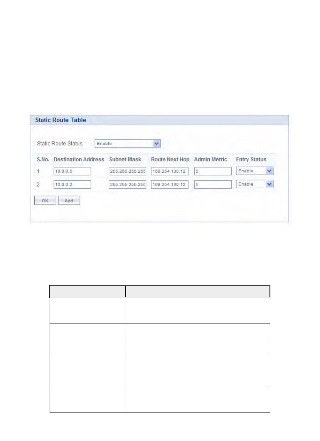
Advanced Configuration
Tsunami QB-8100 Series (100 Mbps/5 Mbps Models) Installation and Management Guide 121
4.11 Routing Features Configuration
4.11.1 Static Route Table (Routing Mode Only)
The static routing table mechanism is available for End Point A and End Point B in routing mode only. It stores the route to
various destinations on the network. When packets are to be routed, the routing table is referred to for the destination
address.
Figure 4-65 Netlp Static Route Table
To set the static routing table
1. Click ADVANCED CONFIGURATION > Network > Static Route Table.
2. Enter the appropriate parameters. See the following table that lists the parameters and their descriptions.
3. Click Add to add a new entry in the table.
Parameter Description
Static Route Status This parameter is used to enable or disable the Static
Route Status. This parameter is applicable to all static
routes.
Destination Address Specifies the destination IP address for which the static
route is to be made.
Route Mask Specifies the subnet mask of the destination IP address.
Route Next Hop Specifies the next hop IP Address through which route
is available to the destination IP address. Next hop IP
should belong to at least one of the subnets connected
to the device.
Metric It is a metric that specifies the distance to the target
usually counted in hops. The priority is given to this
route relative to others. It can range from 0 – 16.
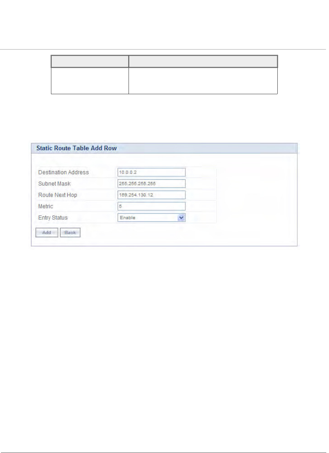
Advanced Configuration
Tsunami QB-8100 Series (100 Mbps/5 Mbps Models) Installation and Management Guide 122
4.11.1.1 Adding Static Route Entries
To add Static Route entries
1. Click Add in the Static Route Table screen. The Static Route Table Add Row screen is displayed as shown below.
Figure 4-66 Static Route Table Add Row
2. After adding the entry into the Static Route table, click Add.
3. Click COMMIT for the changes to take effect.
NOTE:
•Maximum 256 entries can be added to the static route table.
•While adding a new entry, the IP address of the Next Hop must be on the subnet of one of the device’s network
interfaces.
4.11.2 NAT (End Point B, Routing Mode Only)
The NAT (Network Address Translation) feature allows hosts on the Ethernet side of the End Point B to transparently access
the public network through the End Point A. All the hosts in the private network can have simultaneous access to the public
network.
The End Point B supports NAPT (Network Address Port Translation) where all private IP addresses are mapped to a single
public IP address and does not support Basic NAT (where private IP addresses are mapped to a pool of public IP addresses).
Both dynamic mapping (allowing private hosts to access hosts in the public network) and static mapping (allowing public
hosts to access hosts in the private network) are supported.
1. Static NAT: Static mapping is used to provide inbound access. The End Point B maps the public IP address and its
transport identifiers to the private IP address (local host address) in the local network. This is used to provide inbound
access to a local server for hosts in the public network. Static port mapping allows only one server of a particular type.
Up to 100 entries are supported in the static port bind table.
Entry Status This parameter is used to configure the status of the
static route. Only enabled routes are considered for
routing the packets.
Parameter Description
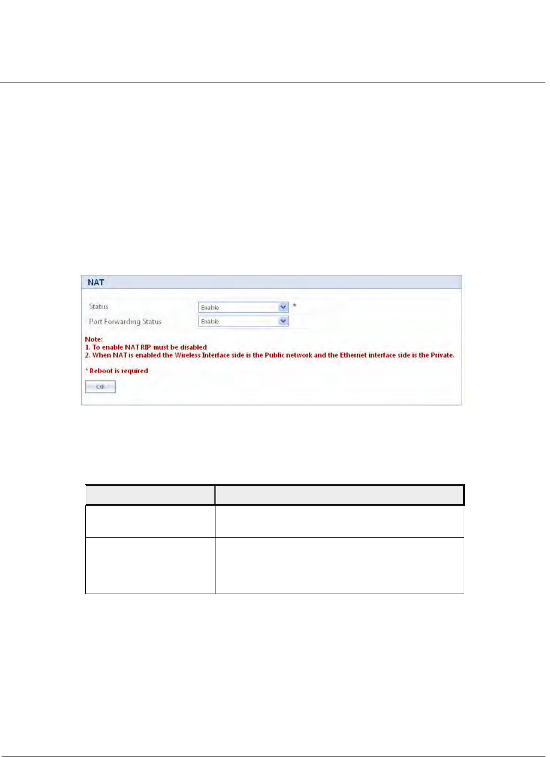
Advanced Configuration
Tsunami QB-8100 Series (100 Mbps/5 Mbps Models) Installation and Management Guide 123
2. Dynamic NAT: In dynamic mapping, the End Point B maps the private IP addresses and its transport identifiers to
transport identifiers of a single Public IP address as they originate sessions to the public network. This is used only for
outbound access.
NOTE:
•When NAT is enabled, the network on the wireless side of the device is considered Public and the network on the
Ethernet side are considered Private.
• When NAT functionality is enabled, the DHCP Relay and RIP features are not supported. The DHCP Relay Agent
and RIP must be disabled before enabling NAT.
To set the NAT parameters,
1. Click ADVANCED CONFIGURATION > Network > NAT. The NAT screen appears as shown below.
Figure 4-67 NAT
2. Enter the appropriate parameters. See the following table that lists the parameters and their descriptions.
3. Click OK.
NOTE:
•To enable Dynamic NAT, set the NAT Status to Enable. To enable Static NAT, set the NAT Status to Enable and
the Port Binding Status to Enable.
•NAT feature is available for End Point B in the routing mode only.
•Any change in the parameters requires a reboot.
•The NAT feature uses the IP address of the wireless interface as the Public IP address.
Field Description
Status This parameter is used to enable or disable NAT
feature.
Port Binding status This parameter is used to enable or disable the Static
NAT feature within different networks. It allows public
hosts to access hosts in a private network. By default, it
is disabled.
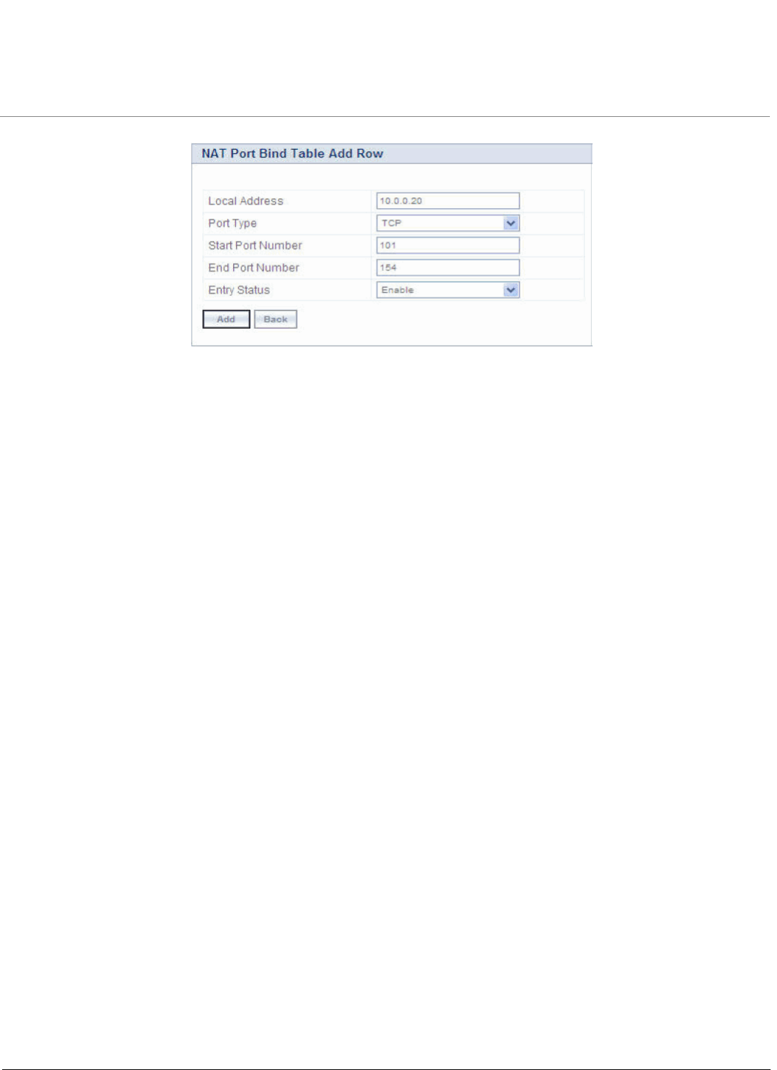
Advanced Configuration
Tsunami QB-8100 Series (100 Mbps/5 Mbps Models) Installation and Management Guide 124
Figure 4-68 NAT Port Bind Table Add Row
To add entries in the NAT static port bind table
1. Enter the Local IP Address of the host on the Ethernet (private) side of the End Point B.
2. Select the Port Type as: TCP, UDP, or Both.
3. Enter the Start Port, End Port and enable the Entry Status.
4. Click Add.
5. After adding the entry into the Static Port Bind Table, click COMMIT and then click REBOOT for the changes to take
effect.
4.11.2.1 Supported Session Protocols
Certain applications require an Application Level Gateway (ALG) to provide the required transparency for an application
running on a host in a private network to connect to its counterpart running on a host in the public network. An ALG may
interact with NAT to set up state information, use NAT state information, modify application-specific payload, and perform
the tasks necessary to get the application running across address realms.
No more than one server of a particular type is supported within the private network behind the End Point B. Following is the
list of supported protocols with their corresponding default ALG's:

Advanced Configuration
Tsunami QB-8100 Series (100 Mbps/5 Mbps Models) Installation and Management Guide 125
4.11.3 RIP (Routing Mode Only)
Routing Information Protocol (RIP) is a dynamic routing protocol, which can be used to automatically propagate routing table
information between routers. The unit can be configured to operate in RIPv1, RIPv2, or both.
When a router receives a routing update including changes to an entry, it updates its routing table to reflect the new route.
RIP maintains only the best route to a destination. Therefore, whenever new information provides a better route, the old
route information is replaced.
NOTE: RIP is configurable only when the unit is in Routing Mode and Network Address Translation (NAT) is disabled.
To enable RIP functionality
•Enable RIP status from the drop-down menu. RIP runs on per interface basis.
To configure RIP parameters
1. Click ADVANCED CONFIGURATION > Network > RIP. The RIP screen is displayed as shown below.
S.No. Protocol Support Applications
1 H.323 H.323 ALG Multimedia Conferencing
2 HTTP Port Mapping for
inbound connection
Web Browser
3 TFTP Port Mapping for
inbound connection
Trivial file transfer
4 Telnet Port Mapping for
inbound connection
Remote login
5 IRC Port Mapping for
inbound connection
Chat and file transfer
6 AMANDA Port Mapping for
inbound connection
Backup and archiving
7 FTP FTP ALG File Transfer
8 PPTP PPTP ALG VPN related
9 NETBIOS Port Mapping for
inbound connection
Applications on different
computers can
communicate within a LAN
10 SNMP SNMP ALG Network Management
11 DNS Port Mapping for
inbound connection
Domain Name Service
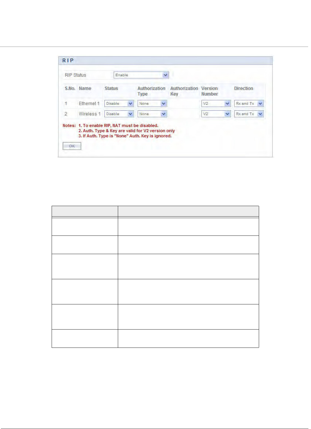
Advanced Configuration
Tsunami QB-8100 Series (100 Mbps/5 Mbps Models) Installation and Management Guide 126
Figure 4-69 Configuring RIP
2. Enter the appropriate parameters. See the following table that lists the parameters and their descriptions.
3. Click OK.
4. Click COMMIT for the changes to take effect.
NOTE:
•Authorization Type and Authorization Key are valid only for RIPV2 and both versions.
•The maximum metric of a RIP network is 15 hops, i.e., a maximum of 15 routers can be traversed between a source
and destination network before a network is considered unreachable.
•By default, a RIP router will broadcast/multicast its complete routing table for every 30 seconds, regardless of
whether anything has changed.
•RIP supports the split horizon, poison reverse and triggered update mechanisms to prevent incorrect routing
updates being propagated.
Parameter Description
Name Displays the name of the interface as Ethernet 1 or
Wireless.
Status This parameter is used to enable or disable RIP for that
particular network interface.
Authorization Type Select the appropriate authorization type. This
parameter is not applicable if RIP v1 is selected as the
Version number.
Authorization Key Enter the authorization key. This parameter is not
applicable if RIP v1 is selected as the Version
number.
Version Number Select RIP Version number from the Version Number
list. Available options are V1, V2 and both. The default
is V2.
Direction Specifies whether RIP is enabled for Receive only or for
both Receive and Transmit.

Tsunami QB-8100 Series (100 Mbps/5 Mbps Models) Installation and Management Guide 127
5
System Management
This chapter provides details about the Management screen of the Web interface and describes the procedures to effectively
manage the Tsunami QB-8100 device.
It covers the following topics:
•System
•File Management
•Services: Configuring the Passwords
•SNTP
•Access Control
•Reset to Factory
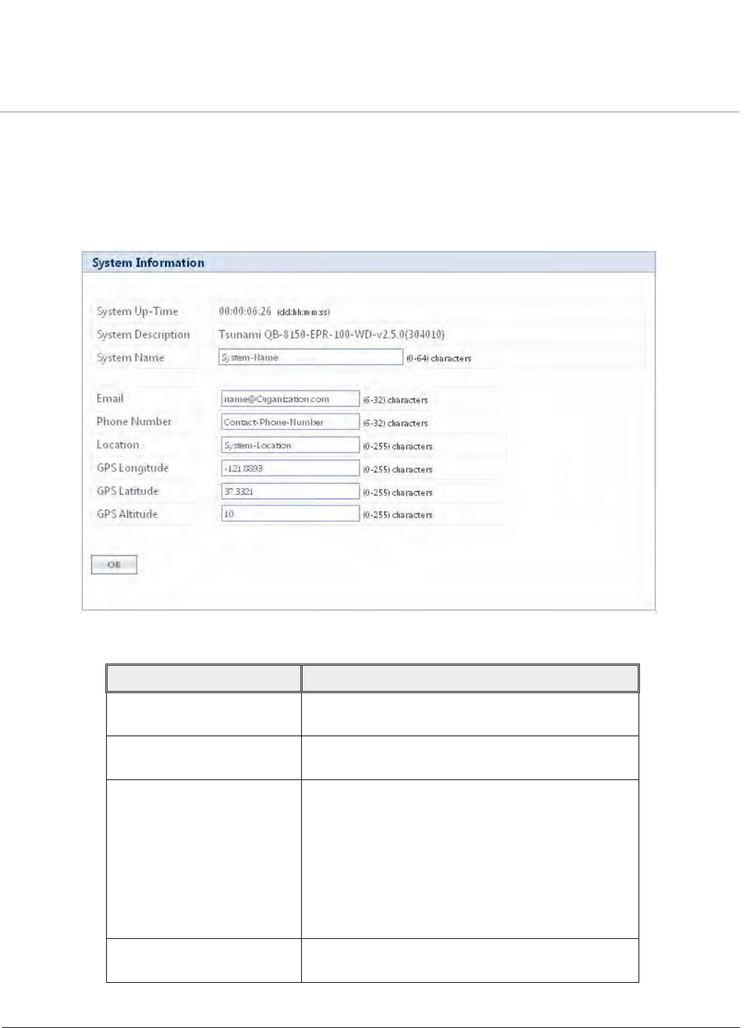
System Management
Tsunami QB-8100 Series (100 Mbps/5 Mbps Models) Installation and Management Guide 128
5.1 System
5.1.1 System Information
This section displays the basic system information. This information further helps in viewing the device details during
troubleshooting. For configuring the system information, click MANAGEMENT > System > Information.
Figure 5-1 System Information
Parameter Description
System Up-Time Specifies the duration of the device running time, since
its last reboot.
System Description Specifies the description of the system. It reports the
device name, current firmware and build number.
System Name Specifies the system name for easy identification of End
Point A or End Point B. The System Name parameter
is limited to a length of 64 characters. Use the System
Name of an End Point A to configure the End Point A
Name parameter on an End Point B if you want the End
Point B to register only with this End Point A. If the End
Point A Name is left blank on the End Point B, it can
register with any End Point A that has a matching
Network Name and Network Secret.
Email Specifies the Email address of the concerned person
responsible for the device.
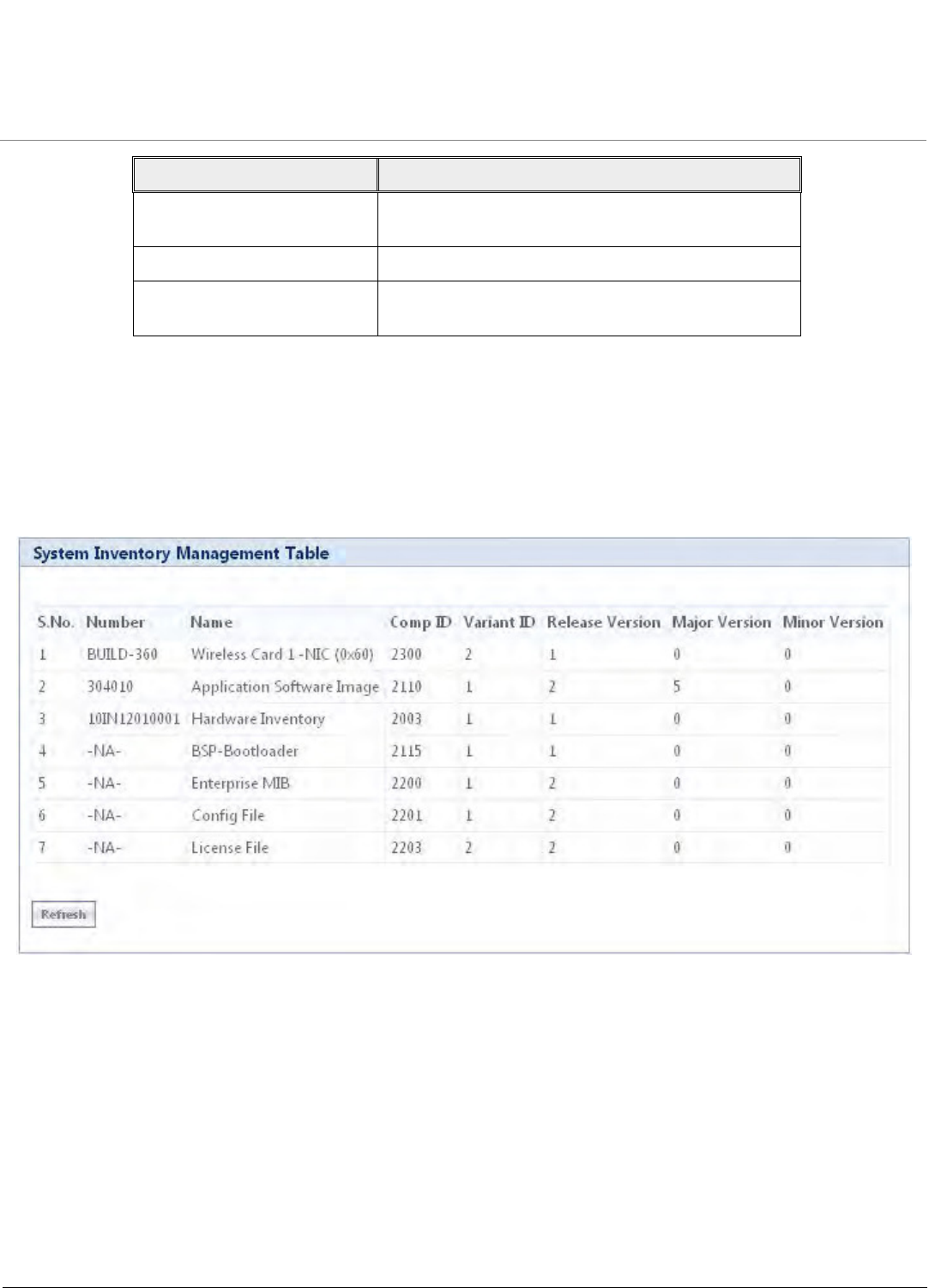
System Management
Tsunami QB-8100 Series (100 Mbps/5 Mbps Models) Installation and Management Guide 129
After setting the system information, click COMMIT for the changes to take effect in the device.
5.1.2 Identifying the Components (Inventory Management)
Inventory management provides complete component information of the device. This section describes the version history of
each component.
To view the details of inventory components, click MANAGEMENT > System > Inventory Management.
Figure 5-2 Inventory Management
By default, the components information is auto-generated by the device. This information is standard and is used only for
reference purpose.
5.1.3 Viewing Licensed Features
Licensing is considered to be the most important component of an enterprise class device which typically has a feature-based
pricing model. It is also required to prevent the misuse and tampering by a wide variety of audience whose motives may be
intentional or accidental.
Licensed Features are, by default, set by the company. To view the licensed features, click MANAGEMENT > System >
Licensed Features. Refer to the parameter description given in the following table:
Phone Number Specifies the Phone number of the concerned person
responsible for the device.
Location Specifies the location of the device.
GPS Longitude, GPS Latitude
and GPS Altitude
Specifies the GPS longitude, latitude and altitude at
which the device is installed.
Parameter Description
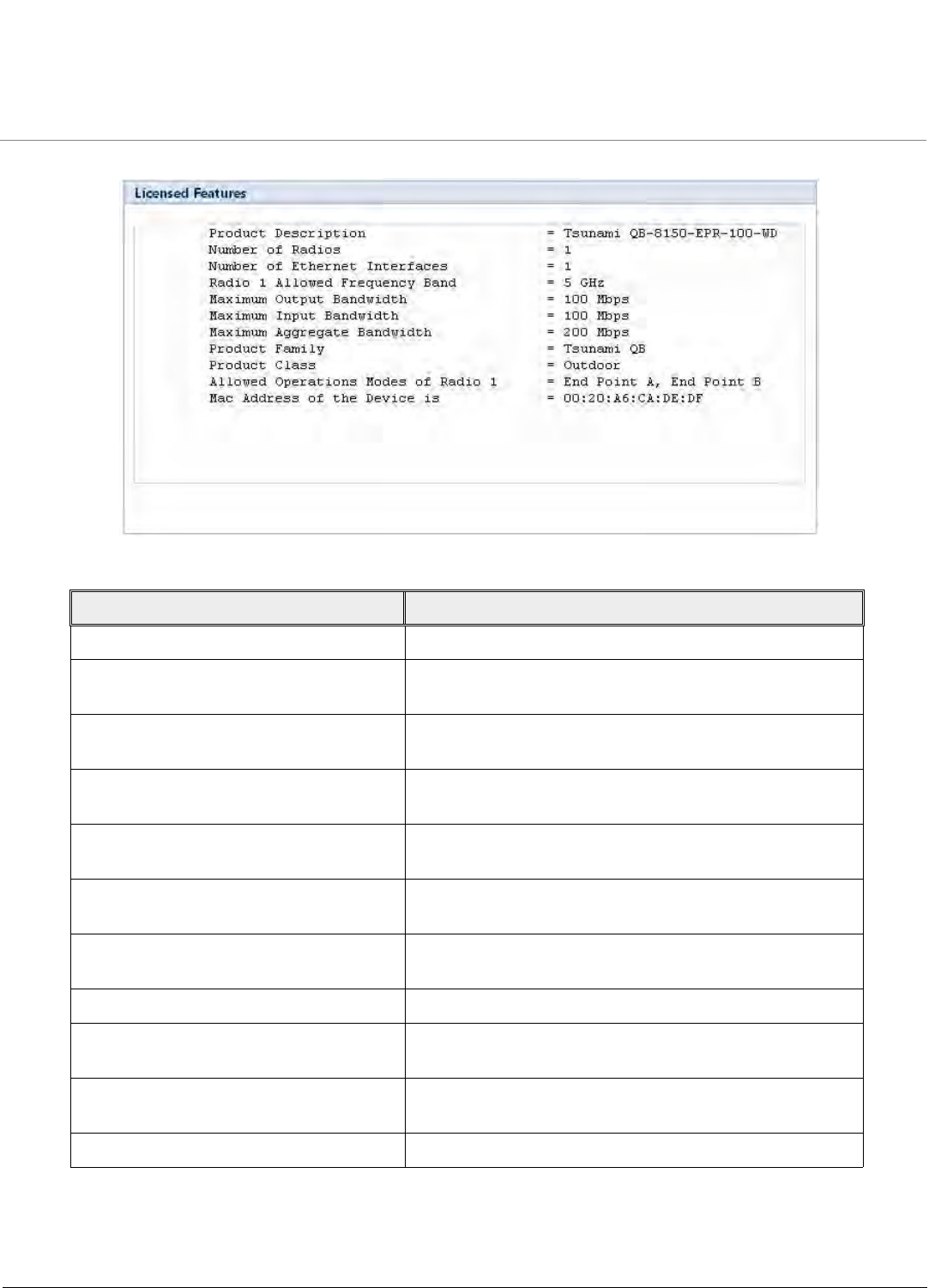
System Management
Tsunami QB-8100 Series (100 Mbps/5 Mbps Models) Installation and Management Guide 130
Figure 5-3 Licensed features
NOTE: The Input and Output Bandwidth features are referred with respect to the wireless interface. That is, input
bandwidth refers to the data received on the wireless interface and output bandwidth refers to the data sent out of
the wireless interface.
Parameter Description
Product Description Specifies the product description.
Number of Radios Specifies the number of radios that the device is licensed to
operate.
Number of Ethernet Interfaces Specifies the number of Ethernet interfaces that the device
is licensed to operate.
Radio 1 Allowed Frequency Band Specifies the wireless operational frequency band supported
by the device.
Maximum Output Bandwidth Specifies the Maximum output bandwidth limit in multiples
of 1Mbps (Refer to Note below).
Maximum Input Bandwidth Specifies the Maximum output bandwidth limit in multiples
of 1Mbps (Refer to Note below).
Maximum Aggregate Bandwidth Specifies the Max cumulative bandwidth of the device
which is the sum of configured output and input.
Product Family Specifies the Product Family of the device.
Product Class Specifies the Product Class of the device. It can be indoor or
outdoor product based on this parameter.
Allowed Operational Modes of Radio1 Specifies the device operational mode as End Point A/End
Point B.
MAC Address of the device is Specifies the MAC address of the device.
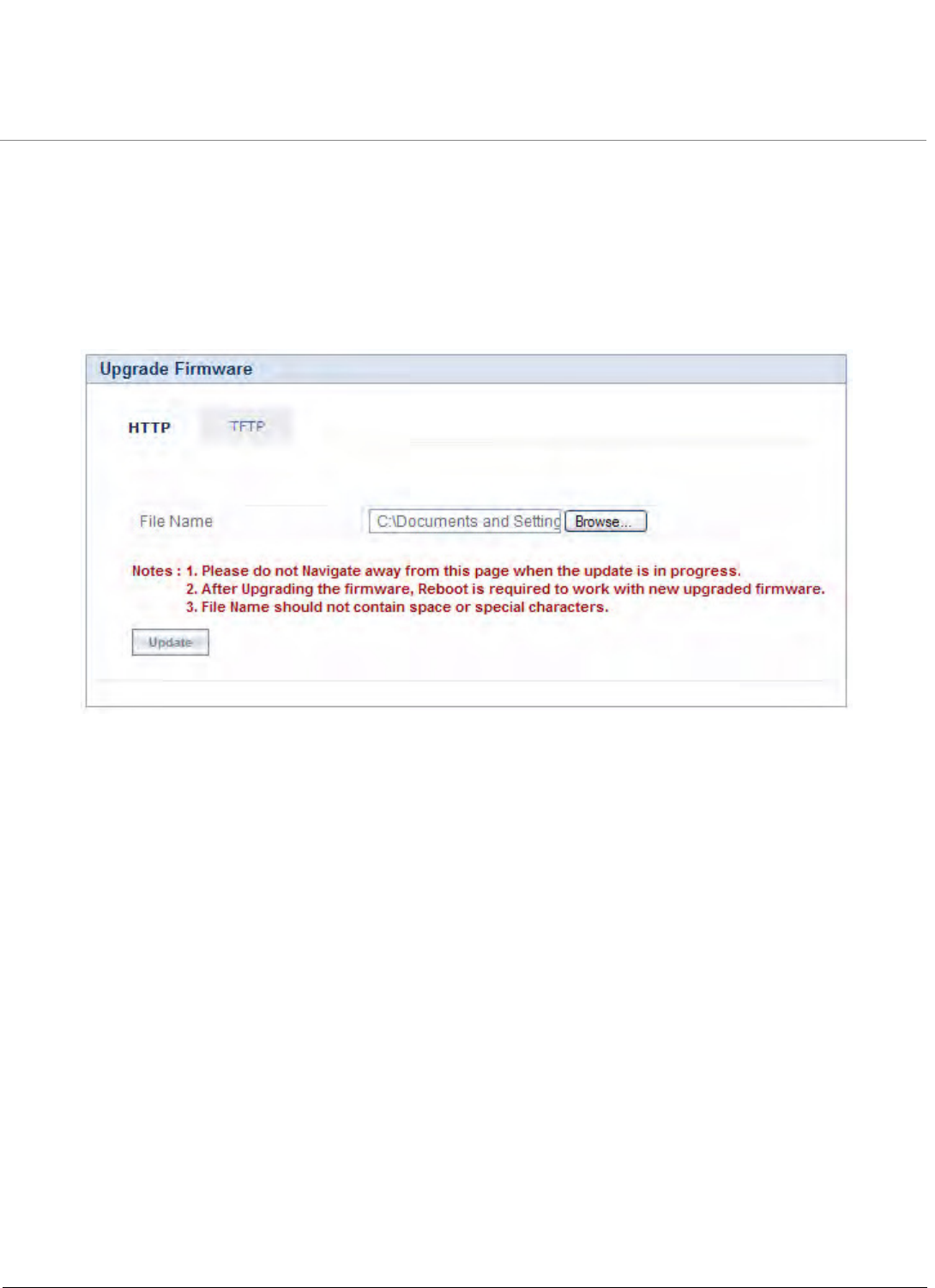
System Management
Tsunami QB-8100 Series (100 Mbps/5 Mbps Models) Installation and Management Guide 131
5.2 File Management
Using this section, you can upgrade the firmware or configuration of the device and also retrieve the log/configuration files
from the device. File Management can be done using TFTP (by using an external TFTP Server) using Web, CLI or SNMP. It can
also be done using the HTTP using Web Interface.
5.2.1 Upgrade Firmware via HTTP
For upgrading the firmware via HTTP web interface, click MANAGEMENT > File Management > Upgrade Firmware > HTTP.
Figure 5-4 HTTP Upgrade Firmware
Steps to upgrade the firmware via HTTP
1. Click Browse and locate the firmware file.
2. Click Update to initiate the HTTP Update operation.
A confirmation message prompts you that a reboot of the device is required for changes to take effect. Click OK and then click
COMMIT to reboot the device for changes to take effect.
NOTE:
•After upgrading new firmware, the device must be rebooted. Until a reboot occurs, the device will continue to run
the firmware it was using before the upgrade started.
•If the user navigates to another page before upgradation is complete, the user may not be able to use the
eventlog/syslog to confirm the status of update.
5.2.2 Upgrade Configuration via HTTP
For updating the configuration via HTTP web interface, click MANAGEMENT > File Management > Upgrade
Configuration > HTTP.
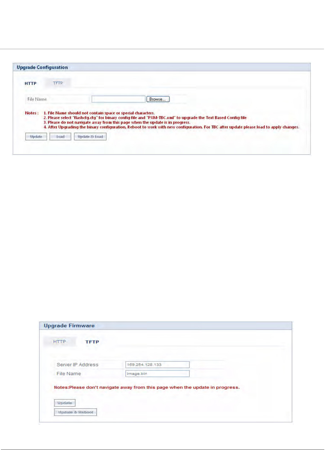
System Management
Tsunami QB-8100 Series (100 Mbps/5 Mbps Models) Installation and Management Guide 132
Figure 5-5 HTTP Update-Configuration
To upgrade the configuration via HTTP
1. Click Browse and locate the configuration file. Select “Flashcfg.cfg” for binary configuration file and “PXM-TBC.xml”
to upgrade the Text Based Configuration file. For more information on how to upgrade the Text Based configuration
file refer to Updating the device with TBC File.
2. Click Update to initiate the HTTP Update operation.
3. Click Load to apply the updated changes.
4. Click Update & load to update and load with new configurations immediately.
NOTES:
•Click COMMIT for the changes to take effect.
•After upgrading new configuration, the device must be rebooted.
5.2.3 Upgrade Firmware via TFTP
Using TFTP, the device can be upgraded with new firmware or configuration file. Also it can be used to retrieve the configuration
or log files from the device.
To upgrade the firmware via TFTP Server, click MANAGEMENT > File Management > Upgrade Firmware > TFTP.
Figure 5-6 Upgrade Firmware-TFTP
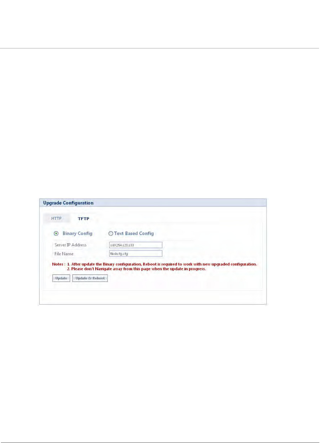
System Management
Tsunami QB-8100 Series (100 Mbps/5 Mbps Models) Installation and Management Guide 133
To upgrade the firmware via TFTP server:
1. Enter the TFTP Server IP Address.
2. Enter the name of the firmware file to update to the device.
3. Click Update to initiate the new firmware updation or click Update and Reboot to update and reboot with new
firmware immediately.
5.2.4 Upgrade Configuration via TFTP
For upgrading the configuration via TFTP Server, click MANAGEMENT > File Management > Upgrade Configuration >
TFTP.
To upgrade the binary configuration file via TFTP server
1. Select the Binary Config option button.
1. Enter the TFTP Server IP Address.
2. Enter the name of the configuration file to be updated to the device.
Click Update to initiate the TFTP update operation or click Update and Reboot to update and reboot with new
configuration immediately.
Figure 5-7 Upgrade Binary Configuration via TFTP
To upgrade the Text Based Configuration file via TFTP server
1. Select the Text Based Config option button. For more information on Text Based configuration file refer to Text
Based Configuration (TBC) File Management.
2. Enter the TFTP Server IP Address.
3. Enter the name of the configuration file to be updated to the device.
•Click Update to initiate the TFTP update operation. Then click Load to apply the updated changes. Finally click
COMMIT for the changes to take effect.
Or
•Click Update & Load to update and load with new configurations immediately and then Click COMMIT for the
changes to take effect.
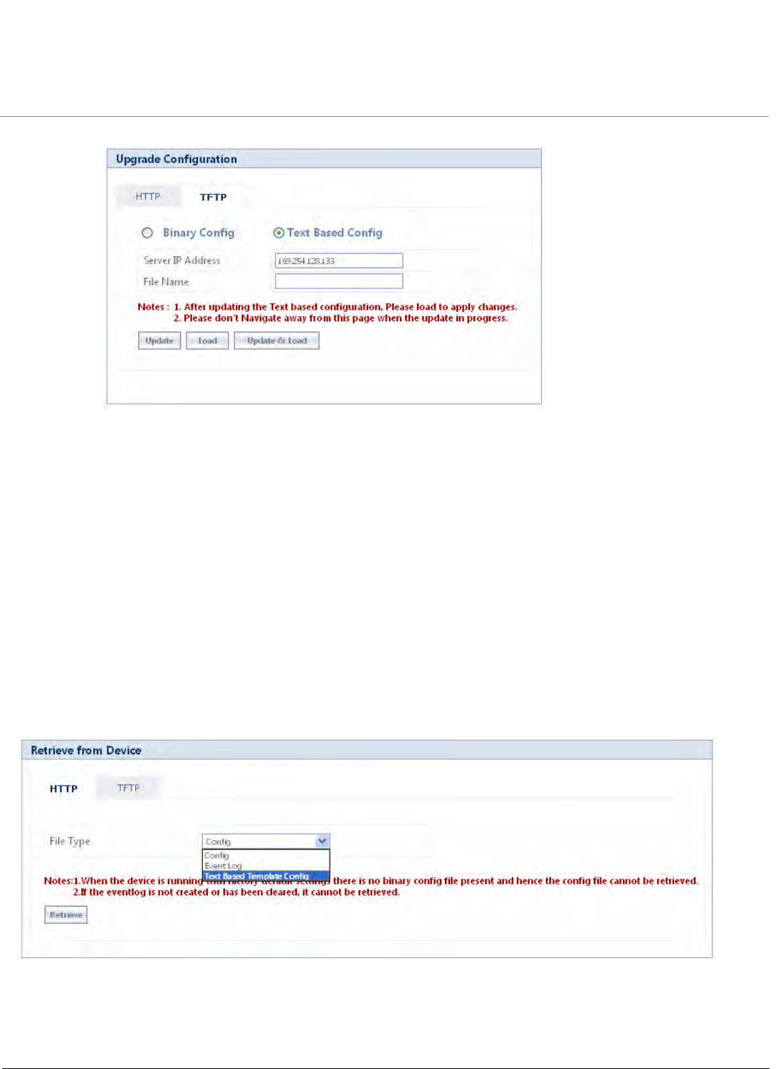
System Management
Tsunami QB-8100 Series (100 Mbps/5 Mbps Models) Installation and Management Guide 134
Figure 5-8 Upgrade Text Based Configuration via TFTP
5.2.5 Retrieve From Device
5.2.5.1 HTTP Retrieve
For retrieving a configuration file or Event log or Text based template configuration file via HTTP web interface, click
MANAGEMENT > File Management > Retrieve From Device > HTTP.
To retrieve files from the device via HTTP
1. From the File Typ e list, select the type of file to retrieve.
a. Config: To retrieve the configuration file from the device.
b. Event Log: To retrieve the event log file from the device.
c. Text Based Template Config: To retrieve the text based template configuration file from the device. For more
information on how to retrieve the Text Based configuration file refer to Retrieving TBC File.
2. Click Retrieve to initiate the operation and retrieve the file to the local system.
Figure 5-9 HTTP Retrieve
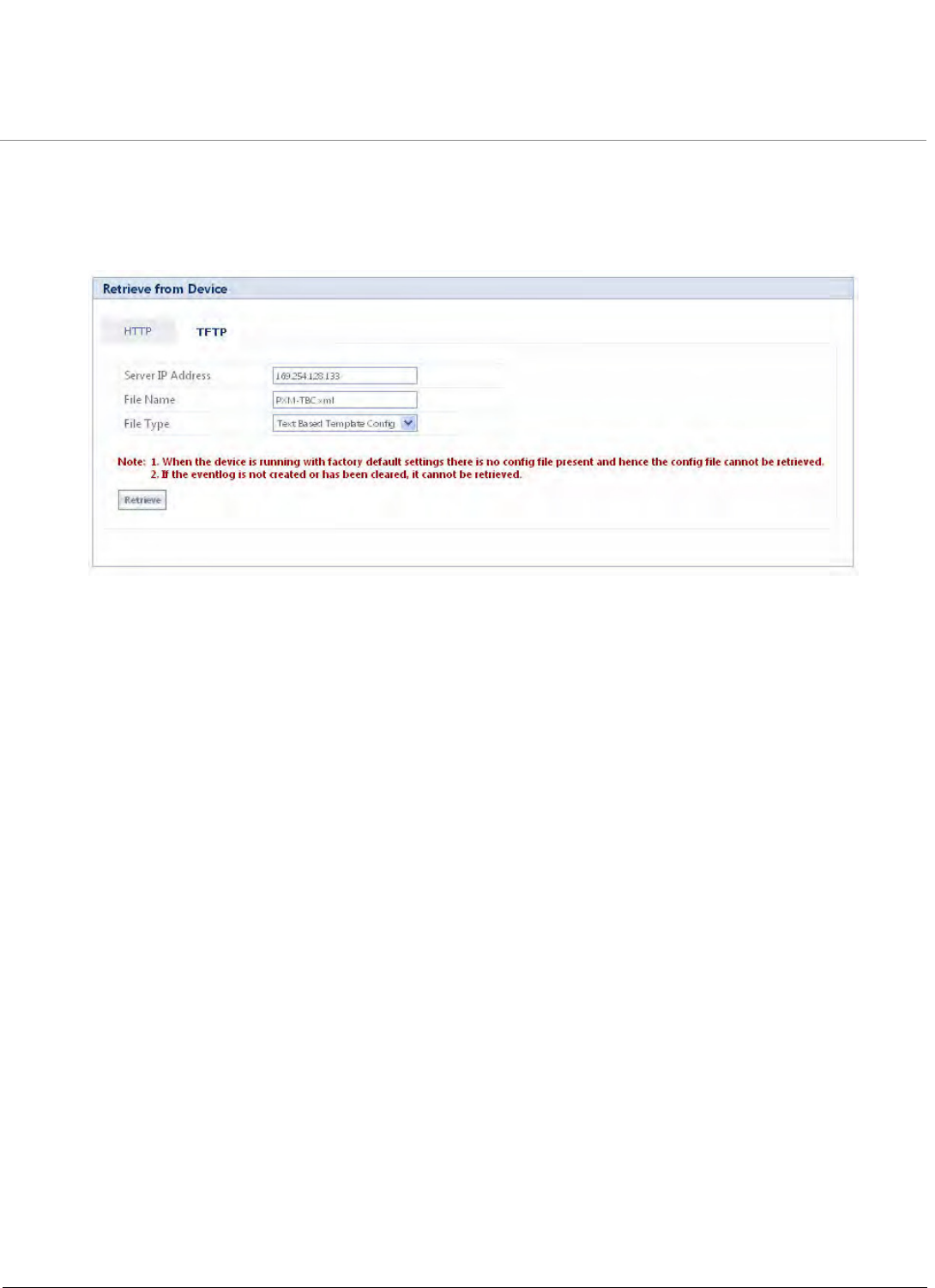
System Management
Tsunami QB-8100 Series (100 Mbps/5 Mbps Models) Installation and Management Guide 135
5.2.5.2 TFTP Retrieve
This option is used to retrieve files from the device to the TFTP server. The TFTP server must be running and configured in the
desired directory path to copy the retrieved file. Assign a proper name to the file which may include version or location
information.
Figure 5-10 TFTP Retrieve
For retrieving a configuration file or Event log file or Text Based Template Configuration file via TFTP web interface, click
MANAGEMENT > File Management > Retrieve From Device > TFTP.
To retrieve files from the device via TFTP Server
1. Enter the TFTP Server IP address.
2. Enter the name of the file to be downloaded to the device.
3. Select the type of file to upgrade from the File Ty p e list:
a. Config: To retrieve the configuration file from the device.
b. Event Log: To retrieve the event log file from the device.
c. Text Based Template Config: To retrieve the text based template configuration file from the device. For more
information on how to retrieve the Text Based configuration file refer to Retrieving TBC File.
4. Click Retrieve to initiate the operation and retrieve the file from the TFTP Server.
NOTE: If the device is in default configuration, there will be no config file to upload. Similarly, Event Log cannot be
uploaded if there is no Event Log created on the device. Also the Text Based Template Configuration file does not
exist if it is not generated from the CLI.
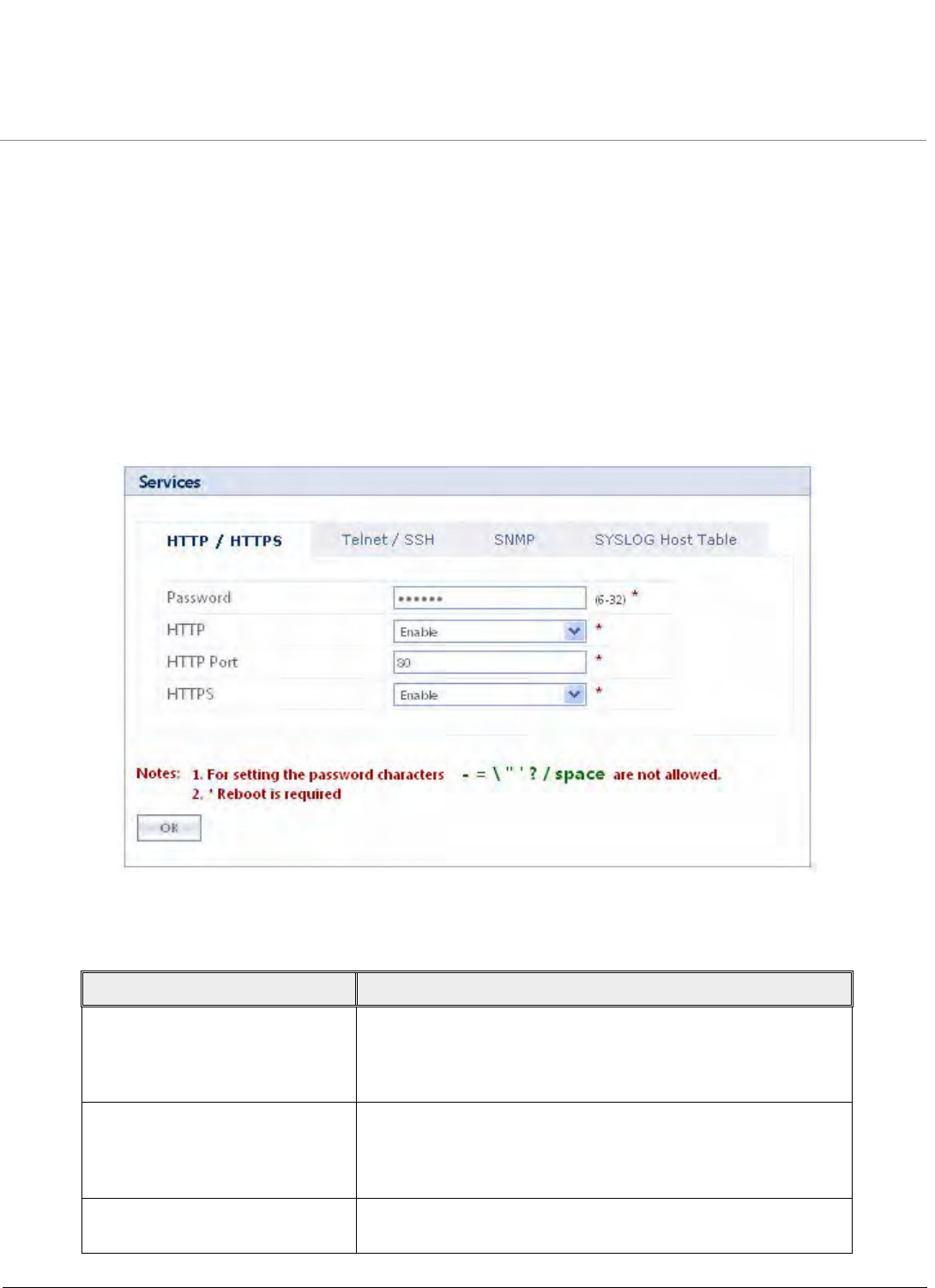
System Management
Tsunami QB-8100 Series (100 Mbps/5 Mbps Models) Installation and Management Guide 136
5.3 Services: Configuring the Passwords
SNMP version, SNMP passwords, and SNMP Trap Host Table parameters can be configured to prevent unauthorized access.
Each management interface can be configured with its own password. Each of the three management interfaces
(HTTP/HTTPS, Telnet/SSH, and SNMP) is arranged in tabs under the Services link of MANAGEMENT tab in the Main Left
Panel.
The following special characters are not allowed for setting passwords for Telnet/SSH, HTTP/HTTPS, and SNMP v2/v3: - / \ ' "
= ? and blank space.
NOTE: The passwords in the Services screen are configurable.
5.3.1 HTTP/HTTPS
Figure 5-11 HTTP/HTTPS
The parameters for HTTP/HTTPS are described in the following table.
Parameter Description
Password Set a new password for the interface or interfaces (Ethernet/
Wireless) to manage the device through the Web interface. Enter
a password between 6 and 32 characters in the Password field.
The default password is “public”.
HTTP Select Enable to allow HTTP access to the device from any host.
You can also select Disable to prevent access to the device from
Web interface. Similar settings are applicable for Hypertext
Transfer Protocol over Secure Socket Layer or HTTPS.
HTTP Port Specifies the port number for HTTP interface. By default, the port
number is 80.
System Management
Tsunami QB-8100 Series (100 Mbps/5 Mbps Models) Installation and Management Guide 137
5.3.2 Telnet/SSH
Figure 5-12 Telnet/SSH
HTTPS Similar settings as mentioned for HTTP. The password
configuration for HTTPS is same as configured for HTTP.
Parameter Description

System Management
Tsunami QB-8100 Series (100 Mbps/5 Mbps Models) Installation and Management Guide 138
The parameters for Telnet/SSH are described in the following table.
Telnet/SSH Parameter settings
Password Set a new password for the interface or interfaces to manage the device
through the CLI. The same password is used for serial CLI also.
Telnet Select Enable to allow the Telnet access to the device from any host. You
can also select Disable to prevent a user from accessing the device from
the CLI. Similar settings are applicable for Secure Shell or SSH.
Telnet P o rt Specifies the port number for Telnet interface. By default, the port
number is 23.
Telnet Sessions Specifies the number of Telnet sessions which controls the number of
active Telnet connections. By default, the number of telnet sessions
allowed is 2.
SSH Select Enable to enable SSH access to the device from any host or select
Disable to prevent a user from accessing the device.
SSH Port Enter the port number for Secure Shell port for CLI interface. By default,
the port number is 22.
SSH Sessions Enter the number of SSH sessions. By default, it is 1 session.
NOTE: Total number of CLI sessions allowed is 3, so the sum of
Telnet and SSH sessions cannot be more than 3. For example, if
you configure the number of Telnet sessions as 2, then the
number of SSH sessions can only be a value from 0 to 1.
System Management
Tsunami QB-8100 Series (100 Mbps/5 Mbps Models) Installation and Management Guide 139
5.3.3 SNMP
Figure 5-13 SNMP
The parameters for SNMP are described in the following table.
SNMP Parameter settings
SNMP This parameter provides the access control for the SNMP
interface. Select Enable/Disable to enable or disable the SNMP
access to the device from any host. Disabling the SNMP will
affect the NMS/PVES access to the device.
Version This parameter configures the SNMP version. The available
versions are v1-v2 and v3. By default, the SNMP starts in version
v2c.
On selecting SNMP v1-v2c, the following parameters need to be
configured. Please refer to the Tsunami QB-8100 Reference
Manual for SNMPv1-v2c Configuration.
System Management
Tsunami QB-8100 Series (100 Mbps/5 Mbps Models) Installation and Management Guide 140
5.3.3.1 SNMPv3 Configuration
Figure 5-14 SNMPv3
Read Password This parameter represents the read only community name used in
SNMP Protocol. It is sent along with each SNMP GET / WALK /
GETNEXT / GETBULK request to allow or deny access to the
device. This password should be same as read password set at
the NMS or MIB browser. The default password is “public” and
range of this parameter must be between 6-32 characters.
Read/Write Password This parameter represents the read-write community name used
in SNMP Protocol. It is sent along with each SNMP GET / WALK /
GETNEXT / SET request to allow or deny access to the device. This
password should be same as read-write password set at the NMS
or MIB browser. The default password is “public” and range of
this parameter must be between 6-32 characters.

System Management
Tsunami QB-8100 Series (100 Mbps/5 Mbps Models) Installation and Management Guide 141
On selecting SNMP V3, the following parameters need to be configured:
5.3.3.2 SNMP Trap Host Table
This table contains the list of IP addresses where the SNMP traps will be delivered. It supports maximum 5 rows.
Adding Entries to the Trap Host Table
To add entries to the Trap Host Table
1. Click Add to add Table Entries to the Trap Host Table.
Figure 5-15 SNMP Host Table Add Row
2. Enter the IP Address, Password, and Comment.
SNMP V3 Parameter settings
Security level The supported security levels for QB-8100 is AuthNoPriv and AuthPriv. Select
AuthNoPriv for Extensible Authentication or AuthPriv for both Authentication
and Privacy (Encryption).
Priv Protocol This field configures the type of privacy (or encryption) protocol. This parameter is
available only when the security level is AuthPriv. Select the encryption standard
either AES-128 (Advanced Encryption Standard) or DES (Data Encryption
Standard) from the list. The default Priv Protocol is AES-128.
Priv Password This field configures the pass key for Privacy protocol selected. This parameter is
available only when the security level is AuthPriv. The default password is
public123 and range of this field must be between 8-32 characters.
Auth Protocol This field configures the type of Authentication protocol. Select the encryption
standard either SHA (Secure Hash Algorithm) or MD5 (Message-Digest algorithm)
from the list. The default Auth Protocol is DES.
Auth Password This configures the pass key for Privacy protocol selected. The default password is
public123 and range of this field must be between 8-32 characters.
The default user in SNMPv3 is “admin” has all read-write privileges and only one
user is supported.
If SNMPv3 is enabled, the v3 stats can be seen in the MONITOR > SNMPv3 stats
page.
System Management
Tsunami QB-8100 Series (100 Mbps/5 Mbps Models) Installation and Management Guide 142
3. Select the entry status as Enable or Disable and click Add.
All traps will be delivered to the host port number 162. The community string/ password field is not valid if the device is
configured in SNMPv3 mode.
NOTE: Changes to SNMP parameters require a Reboot to take effect.
5.3.4 System Log Host Table
System log messages are generated by the system by sending requests at various instances to the system log server. The
priority with which the messages are to be logged from the configured instance can be reconfigured by selecting a desired
priority from the Log Priority drop-down menu. These system log details are lost on system reboot. System message logging
can be disabled if needed.
NOTE:When a particular priority is selected, the messages with a priority higher than the value selected will also be
logged. Change of priority does not change the priority of the messages already logged but only specifies the priority
of future messages to be logged.
To configure the System Log settings
1. Select a Log Status from the drop-down list.
2. Select a required Log Priority from the drop-down list: Emergency, Alert, Critical, Error, Warning, Notice, Info or
Debug.
3. Click OK.
Figure 5-16 Syslog Host Table
To add entries to the System Log Host Table
1. Click Add to display SYSLOG Host Table Add Row page.
2. Enter the parameters listed in the following table.
3. Click Add.
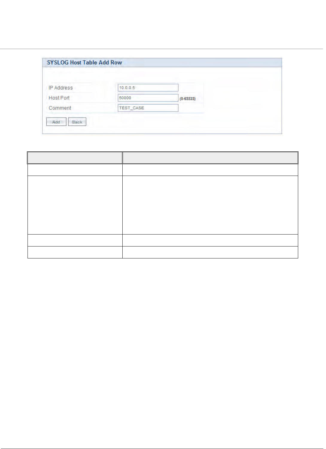
System Management
Tsunami QB-8100 Series (100 Mbps/5 Mbps Models) Installation and Management Guide 143
Figure 5-17 SYSLOG Host Table Add Row
Parameter Description
IP Address Represents the IP address of the SYSLOG server.
Port Represents the host port number. Default port is 514.
NOTE: The user must configure the correct port number on
which the syslog server is running for the Host Port
parameter. Choice of port number must be in line
with the standards for port number assignments
defined by Internet Assigned Numbers
Authority (IANA).
Host Comment Used to provide a note for the device administrator.
Entry Status Used to configure the status of the Syslog host entry table.
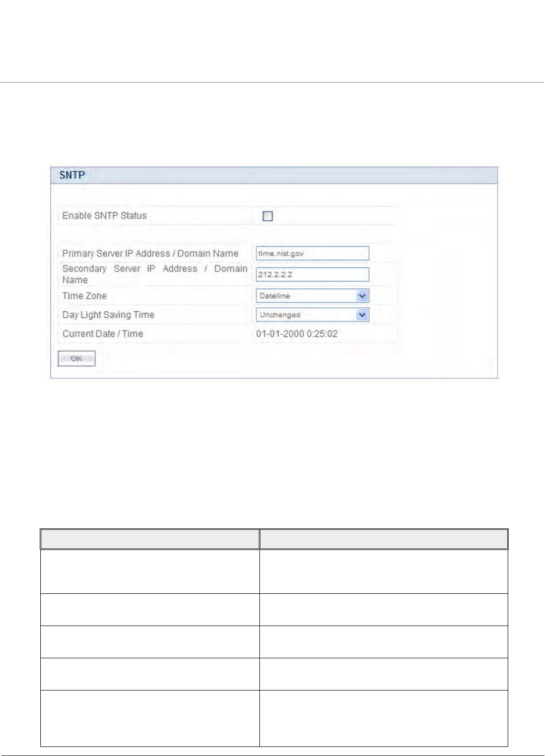
System Management
Tsunami QB-8100 Series (100 Mbps/5 Mbps Models) Installation and Management Guide 144
5.4 SNTP
SNTP allows a network entity to communicate with time servers in the network/Internet to retrieve and synchronize the time
of day information. When this feature is enabled, the system attempts to retrieve the time of day information from the
configured time servers (primary or secondary); and when successful, it updates the relevant time objects in the system.
Figure 5-18 SNTP
To configure and view parameters within the SNTP screen
1. Click MANAGEMENT > SNTP.
2. Select the Enable SNTP Status checkbox. The selected status determines which of the parameters on the SNTP page
are configurable.
3. Enter the parameters listed the following table.
4. Click OK.
5. Click COMMIT for the changes to take effect.
Parameter Description
Primary Server IP Address/Domain Name Specifies the host name or the IP address of the
primary SNTP server. Either a domain name or an IP
address can be provided.
Secondary Server IP Address/Domain Name This optional parameter specifies the host name or an
IP address of the secondary SNTP server.
Time Zone This parameter specifies the time zone set for the
SNTP.
Day Light Saving Time Specifies the number of hours adjusted for Daylight
Saving Time.
Current Date/Time Displays current date and time. If SNTP is not enabled,
the current date and time are automatically generated
from the local system. If SNTP is enabled, it displays the
time the device has got from the SNTP server.
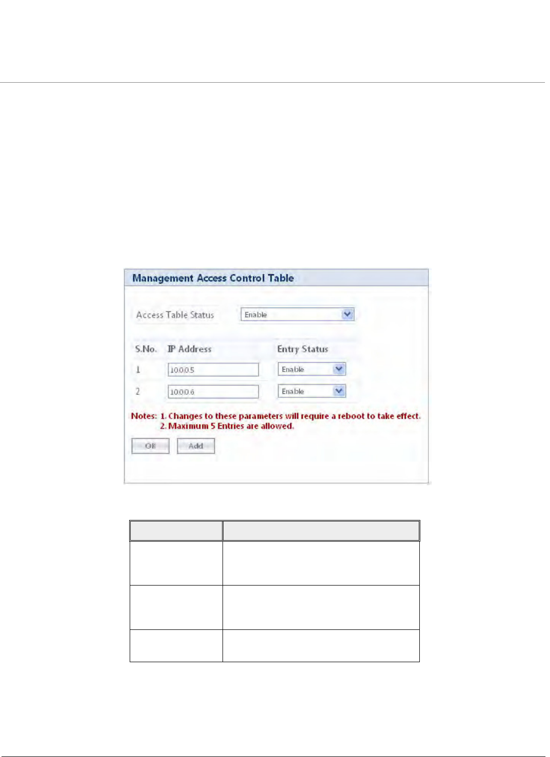
System Management
Tsunami QB-8100 Series (100 Mbps/5 Mbps Models) Installation and Management Guide 145
NOTE:
•Provide the Primary and Secondary Server details only if the SNTP status is enabled.
•For any reason, if the servers configured are not responding, the SNTP client retries every minute.
5.5 Access Control
The Management Access Control feature provides the option of controlling the management interfaces only from the specified
hosts. The user needs to update the table with an IP address, which provides access to management interfaces, such as SNMP,
HTTP, HTTPS, TELNET, and SSH.
To view and configure the Access Table Status and Management Access Control Table, click MANAGEMENT > Access
Control.
Figure 5-19 Management Access Control Table
To add a new IP Address, follow these steps
1. Select Enable for the Access Table Status.
2. Click Add to display the Management Access Table Add Row page.
Parameter Description
Access Table
Status
Enable or disable the Management Access
Control Table status. By default, it is
disabled.
IP Address Specifies the IP Address of the machine to
which the management traffic needs to be
allowed.
Entry Status Used to enable/disable a particular entry in
the Management Access Table.
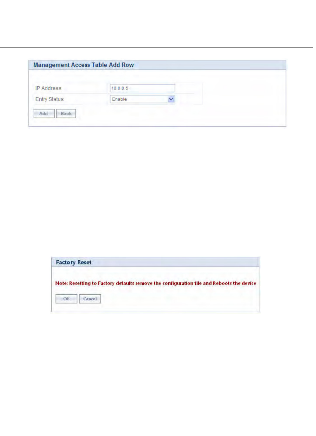
System Management
Tsunami QB-8100 Series (100 Mbps/5 Mbps Models) Installation and Management Guide 146
Figure 5-20 Management Access Table Add Row
3. Enter the IP Address of the device.
4. Select Enable or Disable for the Entry status of the device.
5. Click Add.
Ensure that the IP address of the management PC that is used to manage the device is present in the table. Otherwise, you will
not be able to manage the device. If this case occurs, try to give the PC correct IP address for management; or else, the device
can be configured via the CLI over the serial port.
5.6 Reset to Factory
Click Reset to Factory to reset the device to its factory default state. This resets the network configuration values, including the
password, IP address, and subnet mask.
•Device will reboot automatically after clicking on the Reset To Factory Defaults. The device comes up with default
configurations after reboot.
Figure 5-21 Factory Reset

Tsunami QB-8100 Series (100 Mbps/5 Mbps Models) Installation and Management Guide 147
6
Monitoring the System
This chapter describes the procedures to monitor the Tsunami QB-8100 using the MONITOR screen of the Web interface. It
covers the following topics:
•Interface Statistics
•WORP Statistics
•Bridge
•Network Layer
•Radius (End Point A only)
•DHCP
•Logs
•Tools
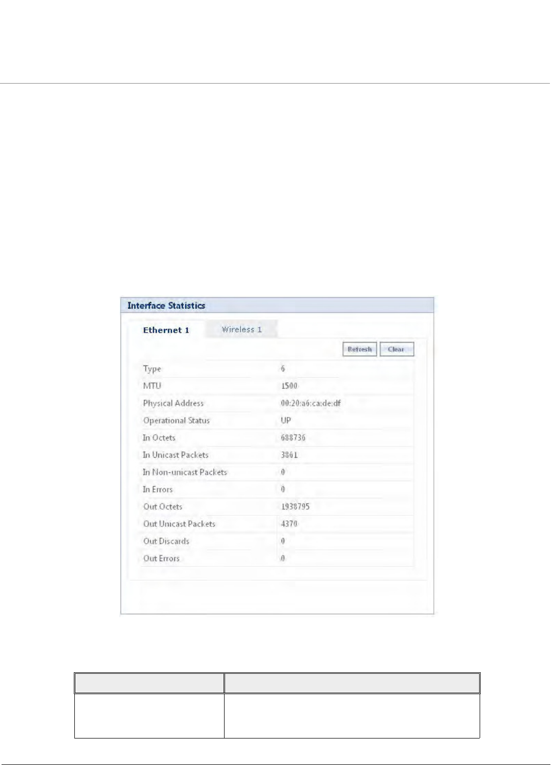
Monitoring the System
Tsunami QB-8100 Series (100 Mbps/5 Mbps Models) Installation and Management Guide 148
6.1 Interface Statistics
Interface Statistics provides detailed information about the data exchanged in both directions through the device interface.
The statistical information include the type of interface, operational status, MAC address of the protocol, number of packets
transmitted, signal information, number of collisions and errors occurred while transmitting the data.
The main function of interface statistics is to monitor and record the status and performance of the ethernet and the wireless
interfaces.
NOTE: For every 4 seconds, statistics pages get refreshed.
6.1.1 Ethernet Statistics
Ethernet Statistics provides you a collection of statistics generated by gathering the network traffic details. Using the statistics,
you can track the number of transactions occurred through this interface.
To view the Ethernet Interface Statistics, click MONITOR > Interface Statistics and click on either Ethernet 1 or Ethernet 2.
Figure 6-1 Ethernet Statistics
The parameters displayed in this page are explained in the following table.
Field Description
Type This parameter displays the type of interface. The
interface type is differentiated based on the network
layers.

Monitoring the System
Tsunami QB-8100 Series (100 Mbps/5 Mbps Models) Installation and Management Guide 149
6.1.2 Wireless Statistics
Wireless Statistics screen displays the details of the wireless interface.
To view the Wireless Statistics, click MONITOR > Interface Statistics > Wireless1.
In addition to the parameters displayed for Ethernet interfaces, the following parameters are displayed for the wireless
interface.
MTU This parameter displays to the largest size of the data
packet received/sent on the interface.
Physical Address This parameter displays the MAC address at the
Ethernet protocol layer.
Operational Status This parameter displays the current operational state of
the interface.
In Octets This parameter displays the total number of the octets
received on the interface.
In Unicast Packets It displays the number of subnetwork- unicast packets
delivered to the higher level protocol.
In Non-Unicast Packets This parameter displays the number of non-unicast
subnetwork packets delivered to the higher level
protocol.
In Errors This parameter displays the number of inbound packets
that contained errors and restricted them from being
delivered.
Out Octets This parameter displays the total number of octets
transmitted out of the interface.
Out Unicast Packets It displays the total number of packets requested by the
higher level protocol and then, transmitted to the
non-unicast address.
Out Discards This parameter displays the number of error-free
outbound packets chosen to be discarded to prevent
them from being transmitted. One possible reason for
discarding such a packet could be to free up buffer
space.
Out Errors It displays the number of outbound packets that could
not be transmitted because of errors.
Parameter Description
RSSI Statistics RSSI stands for Received Signal Strength Indicator. For receiving
strong signal, the RSSI should be high.
This section displays the Receiver statistics. It indicates the power
viewed across the receiver input.
Field Description

Monitoring the System
Tsunami QB-8100 Series (100 Mbps/5 Mbps Models) Installation and Management Guide 150
Antenna Specifies all the antenna ports available for the product. This is
based on the product option. For QB-8100, it shows A1and A2.
Status Specifies the configuration status of the antenna ports. ON
indicates that antenna port is enable for that chain. OFF means
antenna port is disabled for that chain.
Control Specifies the RSSI value of the packet received on the selected
channel.
Extension Specifies RSSI value of the packets received on the adjacent channel
(20MHz). This parameter is applicable only for the 40 MHz modes,
i.e., 40 Plus and 40 Minus modes.
Rx Error Details
Decrypt Errors This parameter is applicable if the Security is enabled. It indicates
the number of received packets that failed to decrypt.
CRC Errors Specifies the number of received packets with invalid CRC.
Parameter Description
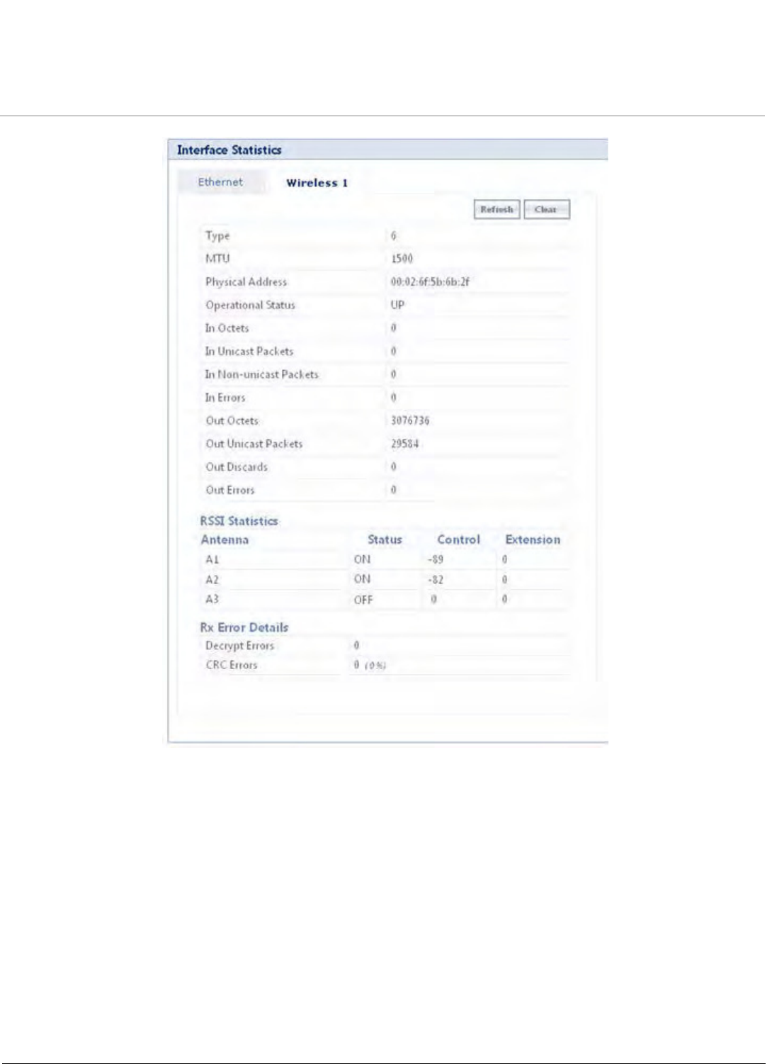
Monitoring the System
Tsunami QB-8100 Series (100 Mbps/5 Mbps Models) Installation and Management Guide 151
Figure 6-2 Wireless Statistics
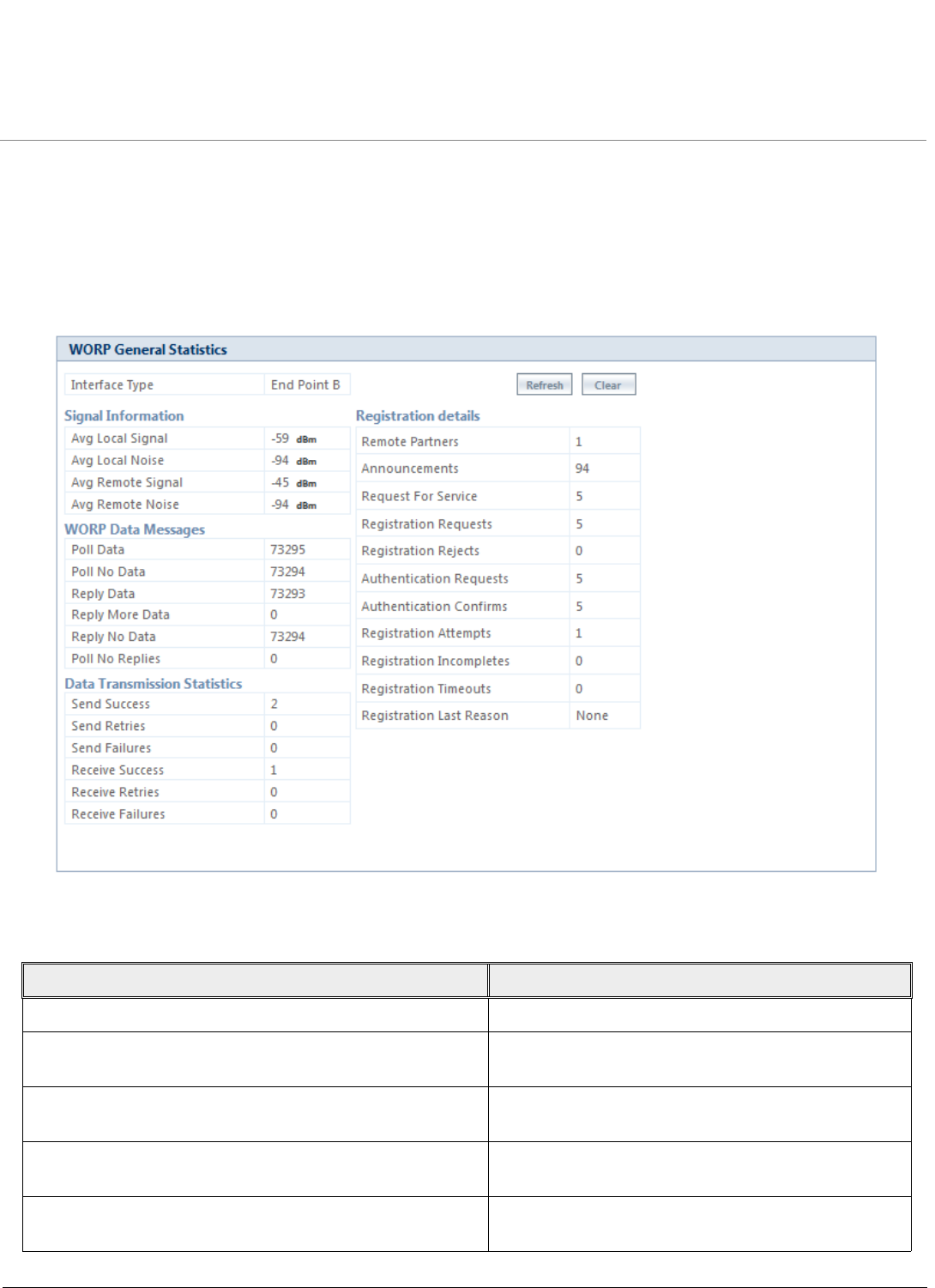
Monitoring the System
Tsunami QB-8100 Series (100 Mbps/5 Mbps Models) Installation and Management Guide 152
6.2 WORP Statistics
6.2.1 General Statistics
WORP General Statistics screen displays the signal information, WORP data messages, Data transmission statistics, and
Registration details of all the data transmitted through the interface.
To view the General Statistics, click MONITOR > WORP Statistics > Interface 1 > General Statistics.
Figure 6-3 WORP General Statistics
The parameters displayed in this page are described in the following table.
Field Description
Interface Type Specifies the type of radio interface.
Signal Information Specifies the SNR details of local and remote devices.
These details are measured in dBm.
Avg Local Signal Refers to the signal level with which the End Point A
received wireless frames from the End Point B.
Avg Local Noise Refers to the noise level with which the End Point A
received wireless frames from the End Point B.
Avg Remote Signal Refers to the signal level with which the End Point B
receives wireless frames from the End Point A.

Monitoring the System
Tsunami QB-8100 Series (100 Mbps/5 Mbps Models) Installation and Management Guide 153
Avg Remote Noise Refers to the noise level with which the End Point B
receives wireless frames from the End Point A.
WORP Data Messages Specifies the sent or received data frames through
wireless interface.
Poll Data Refers to the number of polls with data messages sent
(End Point A) or received (End Point B).
Poll No Data Refers to the number of polls with no data messages
sent (End Point A) or received (End Point B).
Reply Data Refers to the number of poll replies with data
messages sent (End Point B) or received (End Point A).
Reply More Data Refers to the number of poll replies with more data
messages sent (End Point B) or received (End Point A).
Reply No Data Refers to the number of poll replies with no data
messages sent (End Point B) or received (End Point A).
Poll No Replies Refers to the number of times poll messages were sent
but no reply was received. This parameter is valid only
on End Point A.
Data Transmission Statistics Specifies the number of transmissions occurred
through the interface.
Send Success Refers to the number of data messages sent and
acknowledged by the peer successfully.
Send Retries Refers to the number of data messages that are
re-transmitted and acknowledged by the peer
successfully.
Send Failures Refers to the number of data messages that requires
re-transmission. These frames are not acknowledged
by the peer.
Receive Success Refers to the number of data messages received and
acknowledged successfully.
Receive Retries Refers to the number of successfully received
re-transmitted data messages.
Receive Failures Refers to the number of data messages that were not
received successfully.
Registration details Specifies the status of the entire registration process.
Remote Partners Refers to the number of remote partners. For an End
Point B, this parameter is always zero or one.
Announcements Refers to the number of Announcement messages sent
(End Point A) or received (End Point B) on WORP
interface.
Field Description

Monitoring the System
Tsunami QB-8100 Series (100 Mbps/5 Mbps Models) Installation and Management Guide 154
NOTE: For better results, the Send Failure/Send Retrieve must be low in comparison to Send Success. The same applies
for Receive Retries/Receive Failure. Click Refresh to update the details in this page.
6.2.2 End Point B Link Statistics (End Point A only)
WORP End Point B Link Statistics provides the information related to the End Point B currently connected to the End Point A.
This operation is available only in End Point A mode operations.
To view the Interface Statistics, click MONITOR > WORP Statistics > Interface 1 > End Point B Link Statistics.
Request For Service Refers to the number of requests for service messages
sent (End Point B) or received (End Point A).
Registration Requests Refers to the number of registration request messages
sent (End Point B) or received (End Point A) on WORP
interface.
Registration Rejects Refers to the number of registration reject messages
sent (End Point A) or received (End Point B) on WORP
interface.
Authentication Requests Refers to the number of authentication request
messages sent (End Point B) or received (End Point A)
on WORP interface.
Authentication Confirms Refers to the number of authentication confirm
messages sent (End Point A) or received (End Point B)
on WORP interface.
Registration Attempts Refers to the number of times a Registration Attempt
has been initiated.
Registration Incompletes Refers to the number of registration attempts that is
not completed yet.
Registration Timeouts Refers to the number of times the registration
procedure timed out.
Registration Last Reason Refers to the reason for why the last registration was
aborted or failed.
Field Description
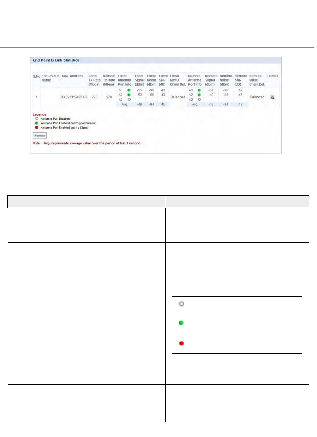
Monitoring the System
Tsunami QB-8100 Series (100 Mbps/5 Mbps Models) Installation and Management Guide 155
Figure 6-4 End Point B Link Statistics
Click Refresh, to get the updated or latest End Point B Link Statistics.
The following table lists the parameters and their descriptions:
Field Description
End Point B Name System name of the End Point B connected.
Mac Address MAC address of the End Point B connected.
Local Tx Rate (Mbps) End Point A Tx Rate.
Remote Tx Rate (Mbps) End Point B Tx Rate.
Local Antenna Port Info Refers to the status of the local antenna port for the
End Point B. This status is shown by three different
legends:
Local Signal (dBm) Refers to the signal level with which the End Point A
received wireless frames from the End Point B.
Local Noise (dBm) Refers to the noise level with which the End Point A
received wireless frames from the End Point B.
Local SNR (dB) Refers to the SNR measured by the receiver at the near
end and is based on the Local Signal and Local Noise.
This legend is displayed when the antenna
port is disabled.
This legend is displayed when the antenna
port is enabled and signal is present.
This legend is displayed when the antenna
port is enabled and signal is not present.
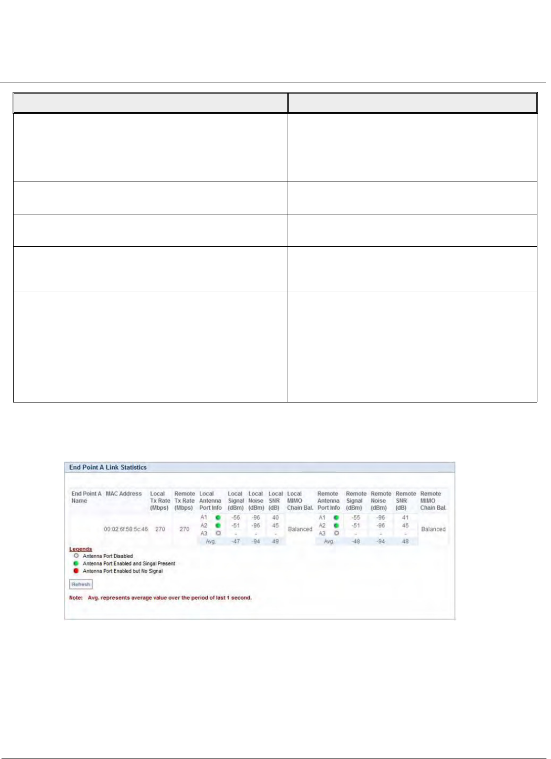
Monitoring the System
Tsunami QB-8100 Series (100 Mbps/5 Mbps Models) Installation and Management Guide 156
6.2.3 End Point A Link Statistics (End Point B Only)
WORP End Point A Link Statistics provides information related to End Point A currently connected to the End Point B.
Figure 6-5 WORP End Point A Link Statistics
Click Refresh, to get the updated or latest End Point A Link Statistics.
6.2.4 QoS Statistics (End Point A Only)
To view the QoS Statistics, click MONITOR > WORP Statistics > Interface 1 > QoS Statistics. This page displays the
Provisioned and Active Bandwidth details on End Point A for the registered End Point B.
Remote Antenna Port Info Refers to the status of the remote antenna port of the
End Point B. The status of the remote antenna port is
shown by three different legends. For more
information on the legends, refer to Local Antenna
Port Info.
Remote Signal (dBm) Signal level with which the End Point B receives
wireless frames from the End Point A.
Remote Noise (dBm) Refers to the noise level with which the End Point B
receives wireless frames from the End Point A.
Remote SNR (dB) Refers to the SNR measured by the receiver at the far
end and is based on the Remote Signal and Remote
Noise.
MIMO Chain Balance Refers to the signal balance between minimum 2 Rx
chains. If the signal balance between two antennas is
greater than 5 dB, then, it is recommended to adjust
the antennas so that MIMO Chain Balance becomes
Balanced or switch to Longer Range Data Stream
settings for reliable wireless link.
NOTE: This field is applicable only for Higher
Throughput data streams.
Field Description
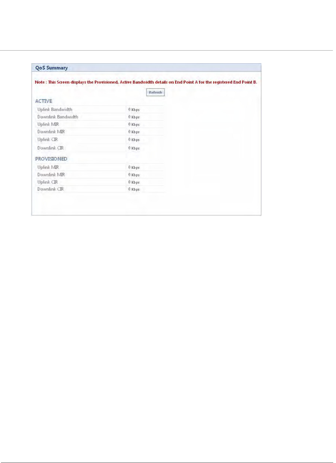
Monitoring the System
Tsunami QB-8100 Series (100 Mbps/5 Mbps Models) Installation and Management Guide 157
Figure 6-6 QoS Summary
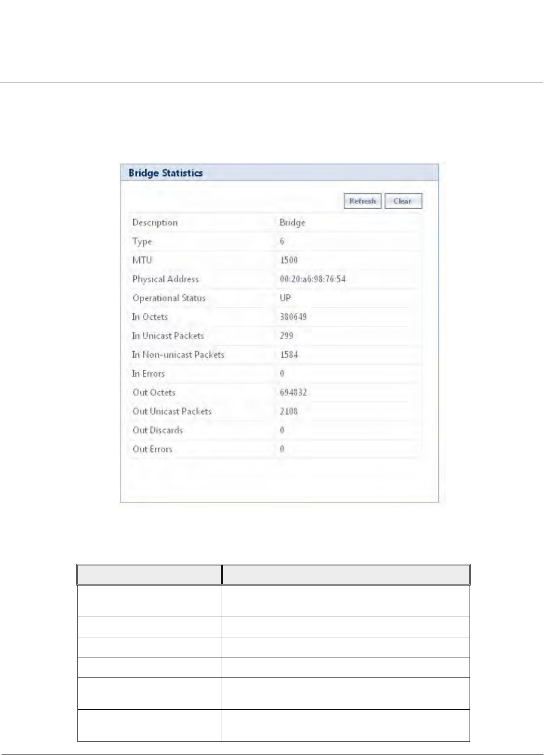
Monitoring the System
Tsunami QB-8100 Series (100 Mbps/5 Mbps Models) Installation and Management Guide 158
6.3 Bridge
6.3.1 Bridge Statistics
To view the Bridge Statistics, click MONITOR > Bridge > Bridge Statistics.
Figure 6-7 Bridge Statistics
The following table lists the parameters and their descriptions:
Parameter Description
Description Displays the textual string containing information
about the interface.
Type Displays the type of interface.
MTU Displays the MTU value.
Physical Address Displays the bridge MAC Address.
Operational Status Displays the current state of the interface: Up (ready to
pass packets) or Down (not ready to pass packets).
In Octets Displays the total number of octets received on the
interface, including the framing characters.

Monitoring the System
Tsunami QB-8100 Series (100 Mbps/5 Mbps Models) Installation and Management Guide 159
6.3.2 Learn Table
Learn Table is used to view all MAC addresses the device has learnt on an interface. The Learn Table displays the information
of learnt MAC addresses, the interface on which it learnt the MAC address, aging timer corresponding to the MAC add entry,
and the type of interface as local interface or attached interface to the device. It reports the MAC address for each node that
the device has learnt on the network and the interface on which the node was detected. There can be up to 10,000 entries in
the Learn Table.
To view the Learn Table entries,
1. Click MONITOR > Bridge > Learn Table.
In Unicast Packets Displays the number of subnetwork unicast packets
received at the bridge interface.
In Non-unicast Packets Displays the number of non-unicast (i.e.,
subnetwork-broadcast or subnetwork-multicast)
packets received at the bridge interface.
In Errors Displays the number of inbound packets that
contained errors and are restricted for delivering them
to a higher-layer protocol at the bridge interface.
Out Octets Displays the total number of octets transmitted out of
the interface, including the framing characters.
Out Unicast Packets Displays the total number of packets requested by
higher-level protocols to be transmitted out of the
interface to a subnetwork-unicast address, including
those that were discarded or not sent.
Out Discards Displays the number of error-free outbound packets
chosen to be discarded to prevent them being
transmitted. One possible reason for discarding such a
packet could be to free up buffer space.
Out Errors Displays the number of outbound packets that could
not be transmitted because of errors.
Parameter Description
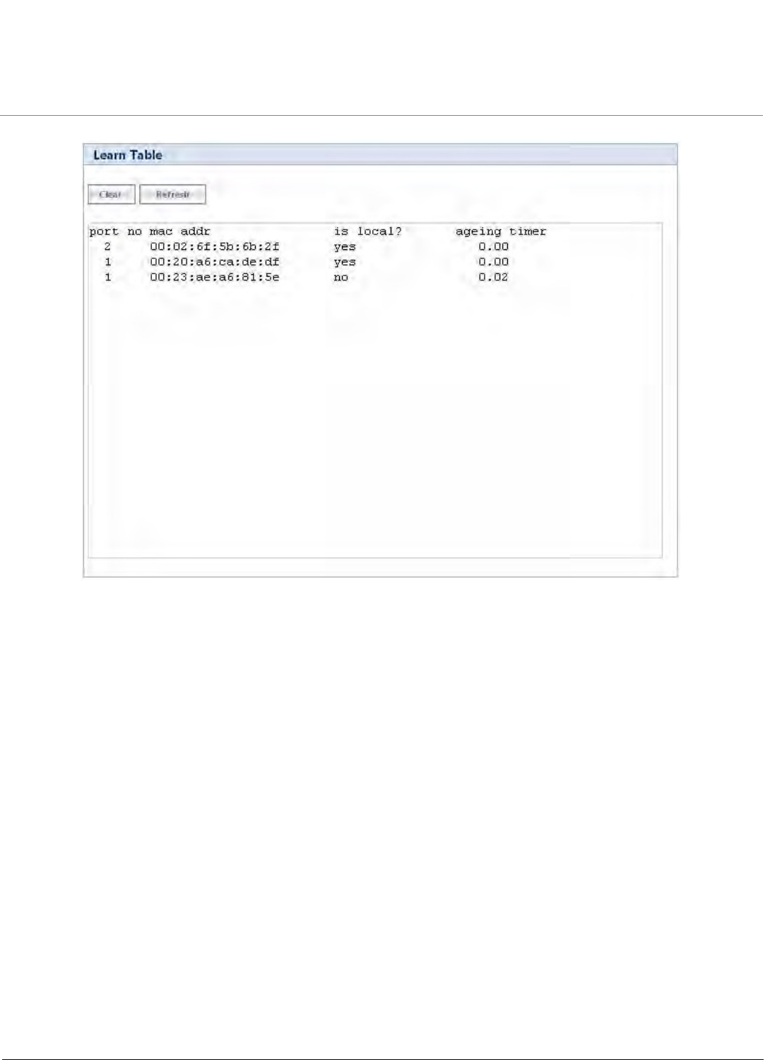
Monitoring the System
Tsunami QB-8100 Series (100 Mbps/5 Mbps Models) Installation and Management Guide 160
Figure 6-8 Learn Table
2. Click Clear to delete all entries of the Learn Table.
3. Click Refresh to get the updated or latest Learn Table.
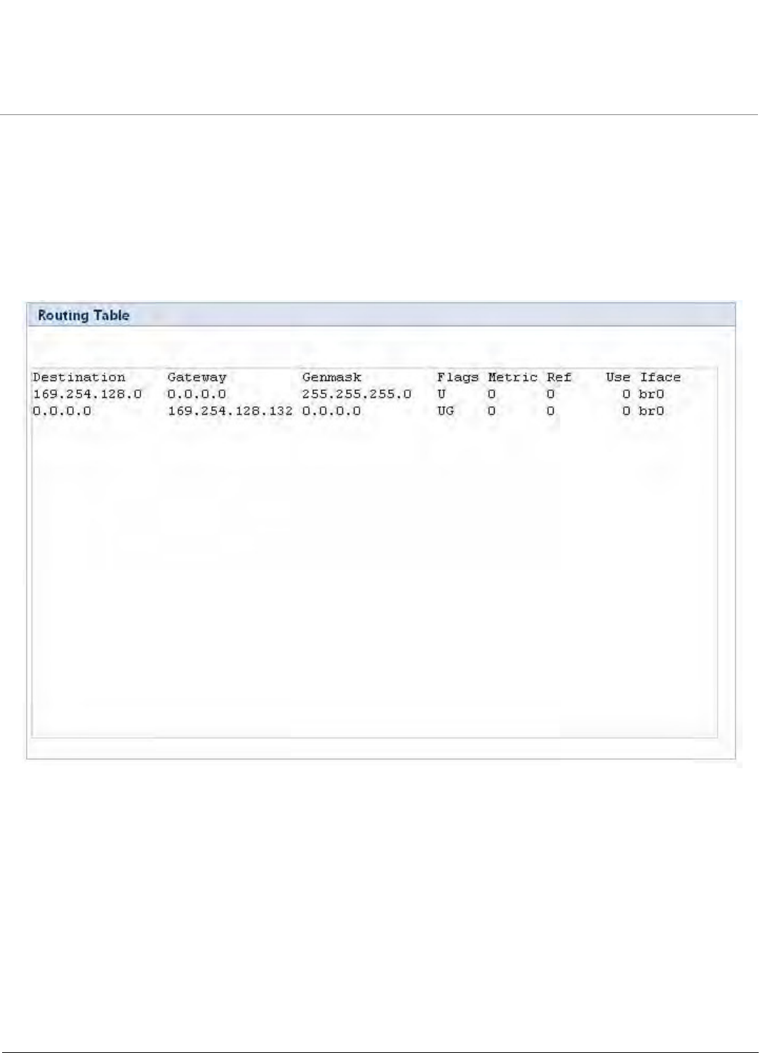
Monitoring the System
Tsunami QB-8100 Series (100 Mbps/5 Mbps Models) Installation and Management Guide 161
6.4 Network Layer
6.4.1 Routing Table
Routing table displays all the active routes of the network. These can be either static or dynamic (obtained through RIP). For
every route created in the network, the details of that particular link or route will get updated in this table.
To view the Routing Table, click MONITOR > Network Layer > Routing Table.
Figure 6-9 Routing Table
6.4.2 IP ARP
This section displays the mapping of the IP and MAC addresses of all nodes in the network. This information is based upon
the Address Resolution Protocol (ARP). ARP is a L2 neighboring protocol which converts the IP address into a physical address
on the Ethernet network.
To view the current ARP table
1. Click MONITOR > Network Layer > IP ARP.
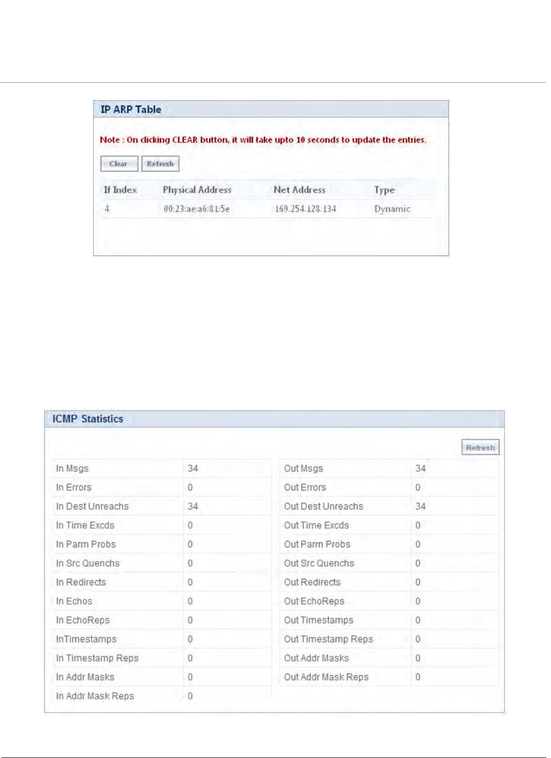
Monitoring the System
Tsunami QB-8100 Series (100 Mbps/5 Mbps Models) Installation and Management Guide 162
Figure 6-10 IP ARP Table
2. Click Clear to delete all entries of the ARP Table.
3. Click Refresh to get the updated or latest ARP Table.
6.4.3 ICMP Statistics
This page provides the statistical information for both received and transmitted messages by the device. The ICMP Statistics
attributes can be used to monitor message traffic.
To view the ICMP Statistics, click MONITOR > Network Layer > ICMP Statistics.
Figure 6-11 ICMP Statistics

Monitoring the System
Tsunami QB-8100 Series (100 Mbps/5 Mbps Models) Installation and Management Guide 163
The following table lists the parameters and their descriptions:
6.4.4 RIP Database
This section shows the information about the RIP database. It contains routes (Routing Information Protocol updates) learnt
from other routers.
Field Description
In Msgs/Out Msgs The number of ICMP messages that are received/transmitted by the
device.
In Errors/Out Errors The number of ICMP messages that the entity received/transmitted but
determined as having errors.
In Dest Unreachs/
Out Dest Unreachs
The number of ICMP Destination Unreachable messages
received/transmitted.
In Time Excds/Out Time Excds The number of ICMP Time Exceeded messages received/transmitted.
In Parm Probs/Out Parm Probs The number of ICMP Parameter Problem messages received/transmitted.
In Srec Quenchs/Out Srec Quenchs The number of ICMP Source Quench messages received/transmitted.
In Redirects/Out Redirects The rate of ICMP Redirect messages received/transmitted.
In Echos The rate of ICMP Echo messages received.
NOTE: Out Echos parameter is not displayed in the ICMP
statistics list.
In EchoReps/Out EchoReps The rate of ICMP Echo Reply messages received/transmitted.
In Timestamps/Out Timestamps The rate of ICMP Timestamp (request) messages received/transmitted.
In Timestamps Reps/
Out Timestamps Reps
The rate of ICMP Timestamp Reply messages received/transmitted.
In Addr Masks/Out Addr Masks The number of ICMP Address Mask Request messages
received/transmitted.
In Addr Mask Reps/ Out Addr Mask
Reps
The number of ICMP Address Mask Reply messages
received/transmitted.
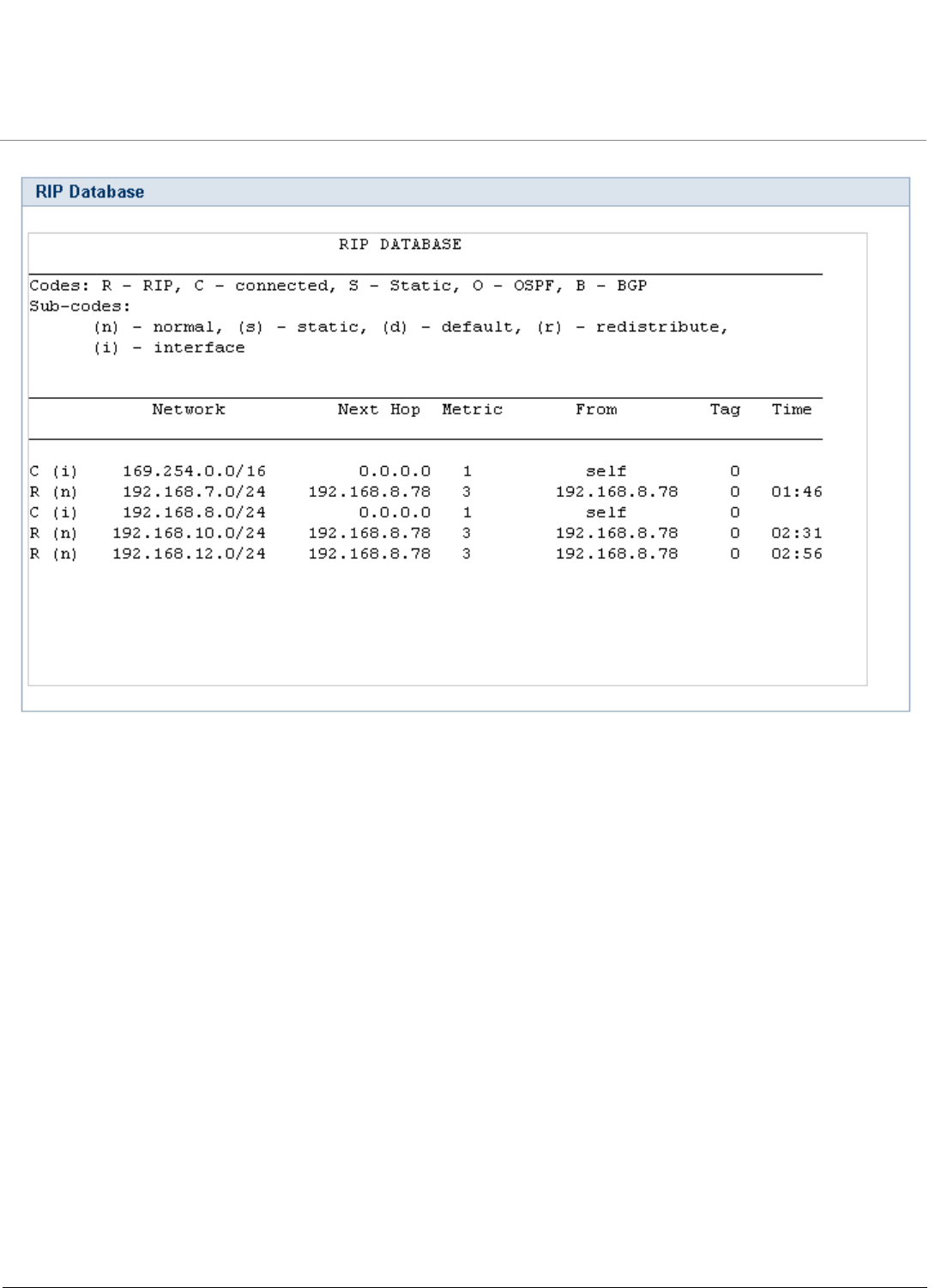
Monitoring the System
Tsunami QB-8100 Series (100 Mbps/5 Mbps Models) Installation and Management Guide 164
Figure 6-12 RIP Database
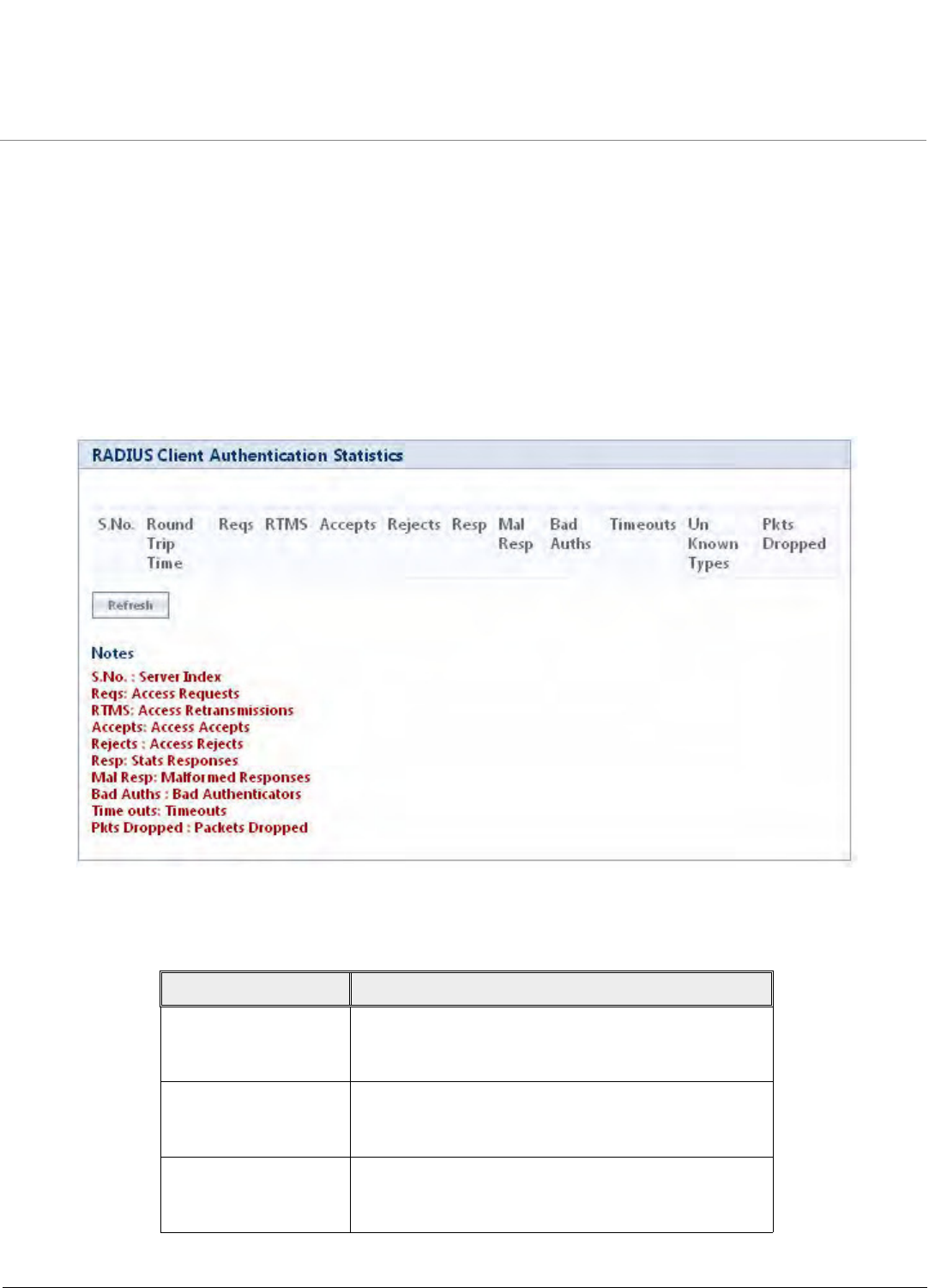
Monitoring the System
Tsunami QB-8100 Series (100 Mbps/5 Mbps Models) Installation and Management Guide 165
6.5 Radius (End Point A only)
This section displays the information about the radius authentication statistics.
NOTE: Radius Client Authentication Statistics are visible only on End Point A.
6.5.1 Radius Authentication Statistics
This page provides information about Radius Authentication for both the primary and backup servers for each radius server
profile.
To view the Radius Client Authentication Statistics table, click MONITOR > Radius > Radius client Authentication
Statistics.
Figure 6-13 Radius Client Authentication Statistics
The Radius Client Authentication Statistics page displays the following parameters.
Field Description
Round Trip Time Specifies the round trip time for messages exchanged
between radius client and authentication server since
client startup.
Reqs Specifies the number of Radius Access Request
messages transmitted from the client to the server
since client startup.
RTMS Specifies the number of times the Radius Access
Requests are being transmitted to the server from the
system since the client startup.

Monitoring the System
Tsunami QB-8100 Series (100 Mbps/5 Mbps Models) Installation and Management Guide 166
Accepts Specifies the number of Radius Access Accept
messages received since client startup.
Rejects Specifies the number of Radius Access Reject messages
received since client startup.
Resp Specifies the number of Radius response packets
received by the system since client startup.
Mal Resp Specifies the number of malformed Radius Access
Response messages received since client startup.
Bad Auths Specifies the number of malformed Radius Access
response messages containing invalid authenticators
received since client startup.
Time Outs Specifies total number of timeouts for radius access
request messages since client startup.
Field Description
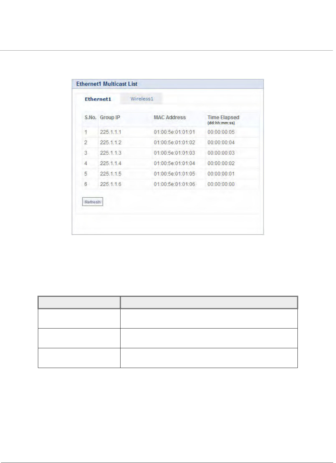
Monitoring the System
Tsunami QB-8100 Series (100 Mbps/5 Mbps Models) Installation and Management Guide 167
6.6 IGMP (Bridge Mode only)
Click MONITOR > IGMP > IGMP Snooping Stats. The Ethernet/Wireless Multicast List screen appears as shown below:
Figure 6-14 Ethernet1 Multicast List
6.6.1 Ethernet/Wireless Multicast List:
1. The Multicast List table holds the IGMP Multicast IP and Multicast MAC address details for the Ethernet/Wireless interfaces.
2. See the following table that lists the parameters and their descriptions.
6.6.2 Router Port List
The Router Port List table shows the list of ports on which multicast routers are attached.
Parameter Description
Group IP This parameter represents the IP address of Multicast group for
Ethernet/Wireless interface learned by IGMP snooping.
Mac Address This parameter represents the MAC address of Multicast group
for Ethernet/Wireless interface learned by IGMP snooping.
Time Elapsed This parameter specifies the time elapsed since the multicast
entry has been created for the Ethernet/Wireless interface.
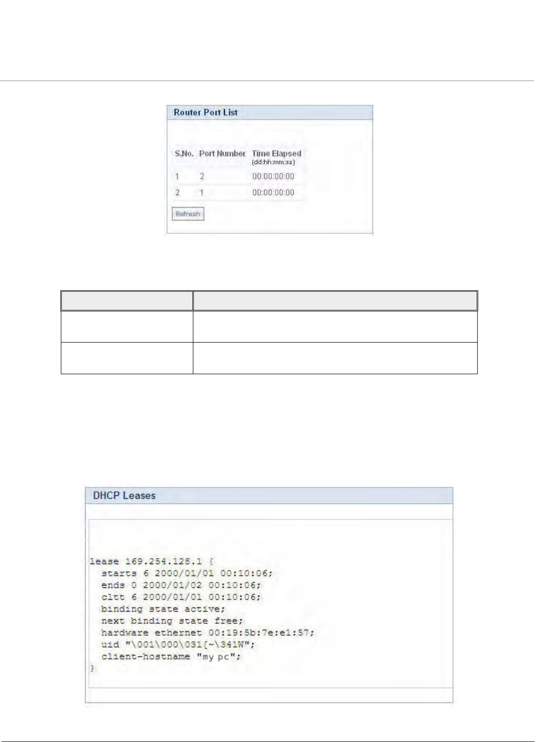
Monitoring the System
Tsunami QB-8100 Series (100 Mbps/5 Mbps Models) Installation and Management Guide 168
Click MONITOR > IGMP > Router Port List. The Router Port List screen appears as shown below:
Figure 6-15 Router Port List
See the following table that lists the parameters and their descriptions.
6.7 DHCP
DHCP Leases file stores the DHCP client database of the DHCP clients that the DHCP Server has served. The information
stored includes the duration of the lease, for which the IP address has been assigned, the start and end dates for the lease,
and the MAC address of the network interface card of the DHCP client.
To view DHCP Leases, click MONITOR > DHCP Leases.
Figure 6-16 DHCP Leases
Parameter Description
Port No This parameter represents the port number on which multicast
router is attached (on which IGMP Query has been received).
Time Elapsed This parameter represents the time elapsed since the port is
marked as the router port.
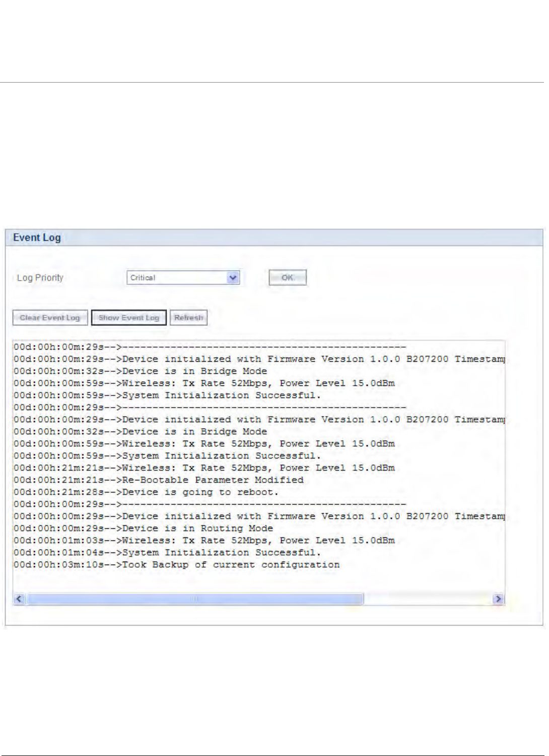
Monitoring the System
Tsunami QB-8100 Series (100 Mbps/5 Mbps Models) Installation and Management Guide 169
6.8 Logs
6.8.1 Event Log
The Event Log keeps track of events that occur during the operation of the device. It displays the event occurring time, event
type, and the name of the error or the error message. Based on the priority, the event details are logged and can be used for
any reference or troubleshooting.
To view the Event Log
1. Click MONITOR > Logs > Event Log. The Event Log screen appears as shown below.
Figure 6-17 Event Log
2. Select the appropriate log priority from the Log Priority drop-down list that has the following options: Emergency,
Alert, Critical, Error, Warning, Notice, Info, and Debug.
NOTE: When Critical is selected, the system logs only critical messages and the messages with higher priority (i.e.,
Emergency and Alert) will be logged from the instance the priority is selected.
3. After setting the event log priority option, click Show Event Log to display the event logs.
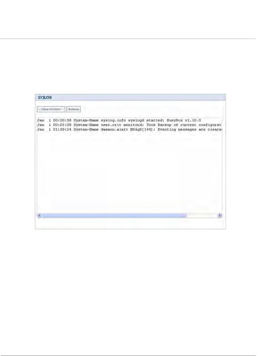
Monitoring the System
Tsunami QB-8100 Series (100 Mbps/5 Mbps Models) Installation and Management Guide 170
•To delete the Event Log, click Clear Event Log.
NOTE: The recent eventlogs are stored in the flash memory.
6.8.2 Syslog
System log messages are generated by the system by sending requests at various instances to the system log server.
Figure 6-18 System Log
•Click Clear SysLog, to clear the SYSLOG information.
•Click Refresh, to get the updated or latest SYSLOG information.
Monitoring the System
Tsunami QB-8100 Series (100 Mbps/5 Mbps Models) Installation and Management Guide 171
6.9 Tools
6.9.1 Link Test
WORP Link Test shows, in graphical form, Signal and Noise levels at which packets are received at local and remote unit.
WORP link test feature is used to monitor the local/remote signal/noise/SNR details of the connected WORP link. During
antenna alignment, this feature can be enabled to monitor the min/cur/max signal details.
NOTE: Internet Explorer 6.0 and its above versions support the link tests.
To view WORP Link Test Statistics, click MONITOR > Tools > Link Test.
Figure 6-19 WORP Link Test
Click Explore Start to explore the established WORP links. Click Refresh to list the details of the registered End Point B.
Please note that only one End Point B gets registered to the associated End Point A. To view the details of a particular End
Point B, select its Link Test Status as Enable. Clicking the Graph icon provides the local/remote station information. After
starting the link test explore, if the user moves out of this page before stopping, exploration is automatically stopped after
Link Test Idle Timeout.
When you set the Link Test Idle Timeout value, the exploring process automatically stops on the given timeout value if you
navigate out of the web page. The default Link Test Idle Timeout is 300 seconds.
The following figure displays the graph for Local/Remote Station information, such as Station Name and MAC address of
both End Point A and End Point B.
Monitoring the System
Tsunami QB-8100 Series (100 Mbps/5 Mbps Models) Installation and Management Guide 172
Figure 6-20 WORP Link Status Graph
To stop the link test, click Explore Stop.
NOTE: Link tests are performed for maximum 3 times. By default, the Link Test Status is disabled.
6.9.2 Wireless Site Survey (End Point B Only)
Wireless Site Survey is done by the End Point B and scans all the available channels and channel bandwidths, and collects
information about all the End Point As on only those channels/bandwidths with the given Network Name. Referring to the
displayed list, you can see which is the best End Point A.
Monitoring the System
Tsunami QB-8100 Series (100 Mbps/5 Mbps Models) Installation and Management Guide 173
Figure 6-21 Wireless Site Survey Table
To initialize the survey process, click Start button. This process lists all the available End Point A details. If you want to stop the
site survey process, click the Stop button.
Click Refresh, to get the updated or latest Wireless Site Survey Table.
NOTE: This survey process is available only for End Point B mode operation.

Tsunami QB-8100 Series (100 Mbps/5 Mbps Models) Installation and Management Guide 174
7
Procedures
This chapter provides details about the various procedures involved in the operation of the QB-8100 units through the Web,
CLI, and SNMP interface.
The following topics are covered in this chapter:
•TFTP Server Setup
•Web Interface Firmware Download
•Configuration Backup
•Configuration Restore
•Text Based Configuration (TBC) File Management
•Hard Reset to Factory Default
•Forced Reload
•Upgrade a New Firmware Using ScanTool in Bootloader Mode
•Download a New Firmware Using CLI from Bootloader

Procedures
Tsunami QB-8100 Series (100 Mbps/5 Mbps Models) Installation and Management Guide 175
7.1 TFTP Server Setup
A Trivial File Transfer Protocol (TFTP) server lets you transfer files across a network. You can retrieve files from the device for
backup or copying, and you can upgrade the firmware or the configuration file. You can download the SolarWinds TFTP
server software from the product installation CD or from http://support.proxim.com. You can also download the latest
TFTP software from SolarWind’s Web site at http://www.solarwinds.net. The following instructions are prepared with an
assumption that you are using the SolarWinds TFTP server software; other TFTP servers may require different configurations.
NOTE: If a TFTP server is not available in the network, you can perform similar file transfer operations using the HTTP
interface.
Ensure the following:
1. The upload or download directory is correctly set (the default directory is C:\TFTP-Root).
2. The required firmware file is present in the directory.
3. The TFTP server is running. The TFTP server must be running only during file upload and download. You can check the
connectivity between the QB-8100 and the TFTP server by pinging the QB-8100 from the computer that hosts the
TFTP server. The ping program should show replies from QB-8100.
4. The TFTP server is configured to both Transmit and Receive files (on the Security tab under File > Configure), with no
automatic shutdown or time-out (on the Auto-Close tab).
7.2 Web Interface Firmware Download
In some cases, it may be necessary to upgrade the embedded software of the unit by downloading the firmware. You can
download the firmware through TFTP or HTTP.
7.2.1 Through TFTP
1. Set up the TFTP server as described in TFTP Server Setup.
2. Access the unit as described in Logging in to the Web Interface.
3. Click Management > File Management > Upgrade Firmware >TFTP tab.
4. Fill in the following details:
•Server IP Address <IP address TFTP server>
•File Name <image file name>
5. Click Update/Update-Reboot to start the file transfer.
The unit downloads the firmware. The TFTP server program should show download activity after a few seconds. When the
download is complete, the unit is ready to start the embedded software upon reboot.
7.2.2 Through HTTP
1. Access the unit as described in Logging in to the Web Interface.
2. Click Management > File Management > Upgrade Firmware > HTTP tab.
3. Fill in the following details:
•File Name <firmware file name>. Using the browse button, select the firmware form the host to be uploaded.
4. Click Update to start the file transfer.
The unit downloads the firmware. When the download is complete, the unit is ready to start the embedded software upon
reboot.

Procedures
Tsunami QB-8100 Series (100 Mbps/5 Mbps Models) Installation and Management Guide 176
7.3 Configuration Backup
You can back up the unit’s configuration by retrieving the configuration file. You can use this file to restore the configuration
or to configure another similar unit (see Configuration Restore). You can update a configuration file through TFTP or HTTP.
7.3.1 Through TFTP
1. Set up the TFTP server as described in TFTP Server Setup.
2. Access the unit as described in Logging in to the Web Interface.
3. Click Management > File Management > Retrieve From Device > TFTP tab.
4. Fill in the following details:
•Server IP Address <IP address TFTP server>
•File Name <configuration file name>
•File Type <configuration file type>
5. Click Retrieve to start the file transfer.
The unit uploads the configuration file. The TFTP server program should show upload activity after a few seconds. When the
upload is complete, the configuration is backed up.
7.3.2 Through HTTP
1. Access the unit as described in Logging in to the Web Interface.
2. Click Management > File Management > Retrieve From Device > HTTP tab.
3. Fill in the following details:
•File Type <configuration file type>
4. Click Retrieve to start the file transfer.
The unit uploads the configuration file. When the upload is complete, the configuration is backed up.
7.4 Configuration Restore
You can restore the configuration of the unit by downloading a configuration file. The configuration file contains the
configuration information of a unit. You can download a configuration file through TFTP or HTTP.
7.4.1 Through TFTP
1. Set up the TFTP server as described in TFTP Server Setup.
2. Access the unit as described in Logging in to the Web Interface.
3. Click Management > File Management > Upgrade Configuration> TFTP tab.
4. Fill in the following details:
•Server IP Address <IP address TFTP server>
•File Name <configuration file name>
5. Click Update/Update-Reboot to start the file transfer.
The unit downloads the configuration file. The TFTP server program should show download activity after a few seconds. In
case of Update and Reboot, when the upgrade is complete and the system rebooted, the configuration is restored.
7.4.2 Through HTTP
1. Access the unit as described in Logging in to the Web Interface.
2. Click Management > File Management > Upgrade Configuration > HTTP tab.

Procedures
Tsunami QB-8100 Series (100 Mbps/5 Mbps Models) Installation and Management Guide 177
3. Fill in the following details:
•File Name <configuration file name>
4. Click Update to start the file transfer.
A reboot is required for the new configuration to be restored into the device.
7.5 Text Based Configuration (TBC) File Management
7.5.1 Text Based Configuration File
Text Based Configuration (TBC) file is a simple text file that holds the template configurations of the device. The 8100 series of
devices supports the TBC file in XML format which can be edited in any XML or text editors.
You can generate the TBC file from the CLI Session and manually edit the configurations and then load the edited TBC file
to the device so that the edited configurations are applied on to the device. It differs mainly with the binary configuration file
in terms of manual edition of configurations. The generated TBC file is a template which has only the default and modified
configurations on that live CLI session.
Downloading/Uploading the TBC File:
The TBC file can be downloaded to or uploaded from the device using all three interfaces (SNMP/WEB/CLI). Either TFTP or
HTTP options can be used to download or upload the TBC file.
NOTE: While downloading the TBC file, any file name is accepted and then the file is renamed to PXM-TBC.xml. If the
mandatory XML tags are missing, the file is not downloaded to the device.
7.5.2 Generating TBC File
Text Based Configuration file is generated only when generate command is given from the Command Line Interface (CLI).
While generating the TBC File from CLI, there is an option to generate it with or without all Management & Security
Passwords. The management passwords include CLI/WEB/SNMP passwords. The security passwords include
Network-Secret/Encryption-Key(s)/RADIUS-Shared-Secret. If included, these passwords become a part of the generated TBC
file and are in a readable form. If excluded, all these passwords are not a part of the generated TBC file.
The commands used for the generation of TBC file are:
T8000-00:00:01# generate tbc-with-pwds
T8000-00:00:01# generate tbc-without-pwds
The generated TBC file contains
•Default configurations with their default values.
•Any user-added or edited configurations on current live CLI session.
7.5.3 Retrieving TBC File
Using the WEB interface, you can retrieve the generated TBC file from the device either through TFTP or HTTP protocol.
7.5.3.1 Retrieving through HTTP
For retrieving a Text based template configuration file via HTTP web interface, click MANAGEMENT > File Management >
Retrieve From Device > HTTP.
Procedures
Tsunami QB-8100 Series (100 Mbps/5 Mbps Models) Installation and Management Guide 178
Figure 7-1 HTTP Retrieve of TBC File
1. From the File Typ e list, select Text Based Template Config file.
2. Click Retrieve to initiate the operation and retrieve the file to the local system.
3. On clicking Retrieve, a Download window appears as shown below. To download and save the file to your local
system, right click on the link HERE, then save the file to your system.
Figure 7-2 Download the TBC File
7.5.3.2 Retrieving through TFTP
For retrieving a Text Based Template Configuration file via TFTP web interface, click MANAGEMENT > File Management >
Retrieve From Device > TFTP.
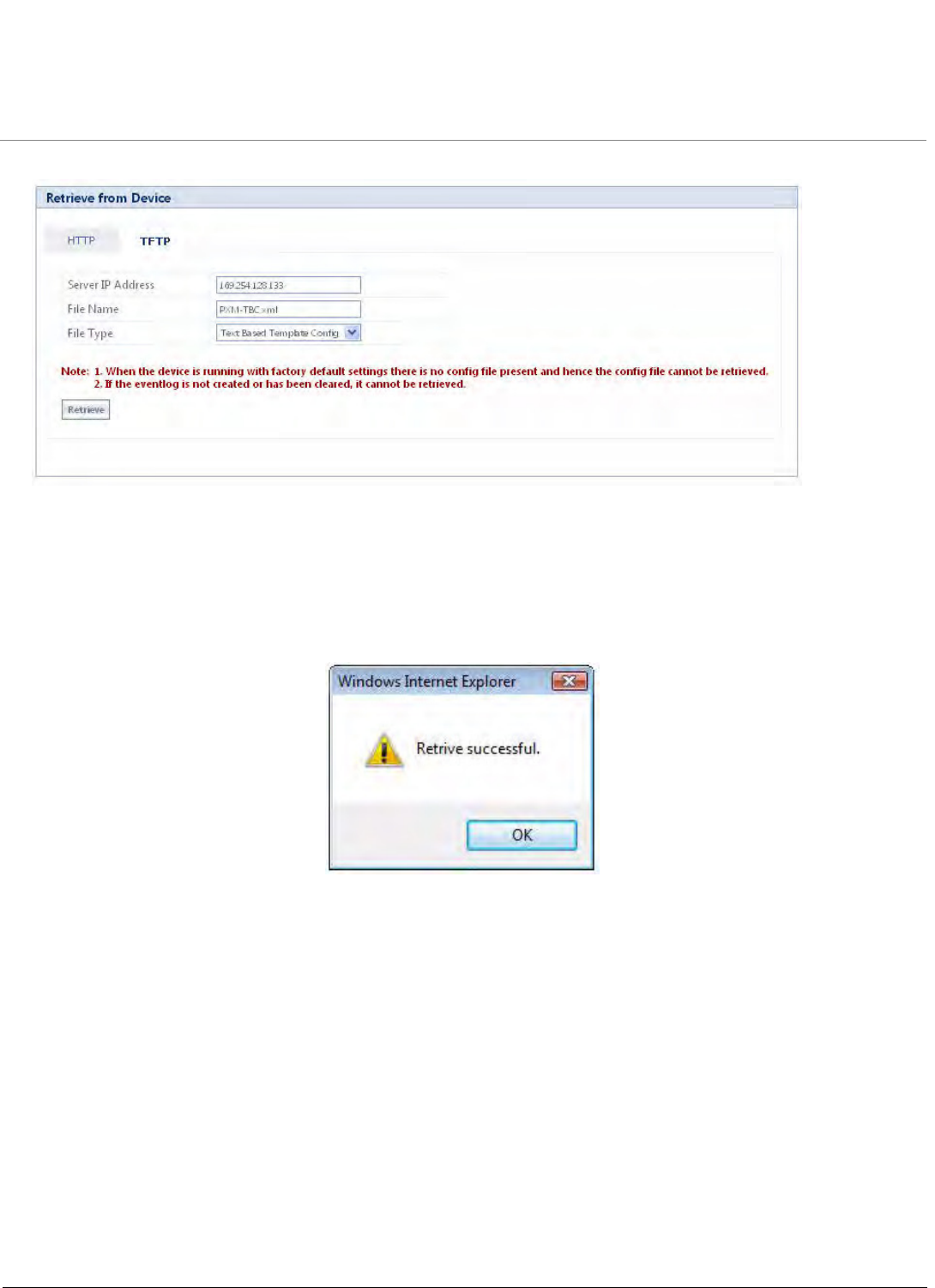
Procedures
Tsunami QB-8100 Series (100 Mbps/5 Mbps Models) Installation and Management Guide 179
Figure 7-3 TFTP Retrieve of TBC File
1. Enter the TFTP Server IP address.
2. Enter the name of the file to be uploaded from the device.
3. Select the file type as Text Based Template Config.
4. To retrieve the file from the TFTP Server, Click Retrieve. The following window appears as shown below:
Figure 7-4 Successful retrieve of TBC
NOTE: The Text Based Template Configuration file does not exist if it is not generated from the CLI.
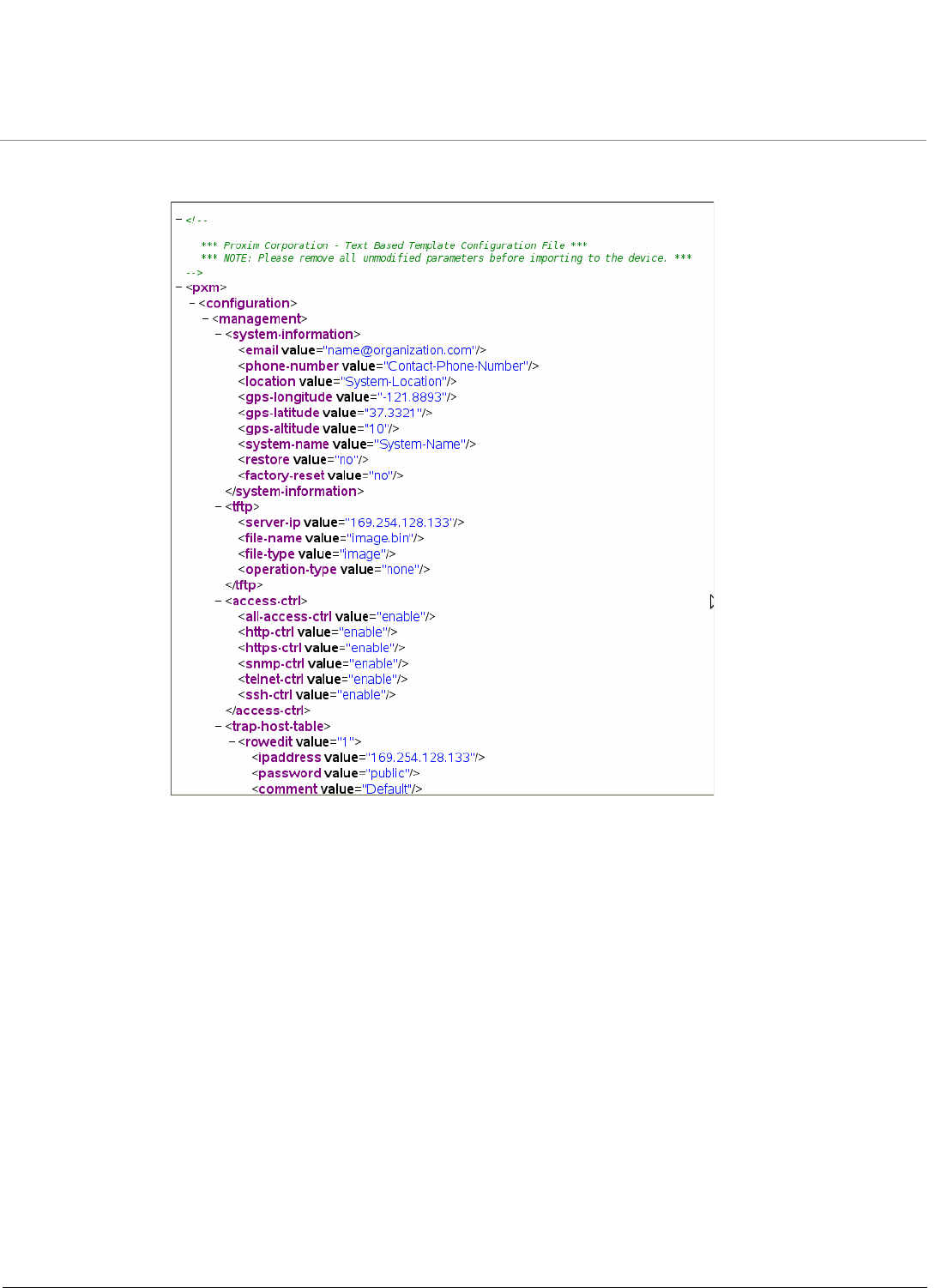
Procedures
Tsunami QB-8100 Series (100 Mbps/5 Mbps Models) Installation and Management Guide 180
The generated Text Based Template Configuration file appears as shown below:
Figure 7-5 TBC File in xml Format
7.5.4 Editing the TBC File
The Text Based Config (TBC) file can easily be opened and edited in any standard Text-Editors like Wordpad, MS-Word,
Notepadd++, Standard XML Editors. Proxim recommends XML Notepad 7 editor for editing the TBC file.
•You can modify any value between the double quotes(““) in the TBC file. It is recommended not to change the text
outside the double quotes (“”) or XML tags in the TBC file.
•Remove unchanged configurations from the TBC file before loading it to the device.
7.5.5 Updating the device with TBC File
You can update the device with the TBC File either through HTTP or TFTP protocol.
7.5.5.1 Updating the device with TBC File via HTTP
For updating the TBC File configuration via HTTP web interface, click MANAGEMENT > File Management > Upgrade
Configuration > HTTP.
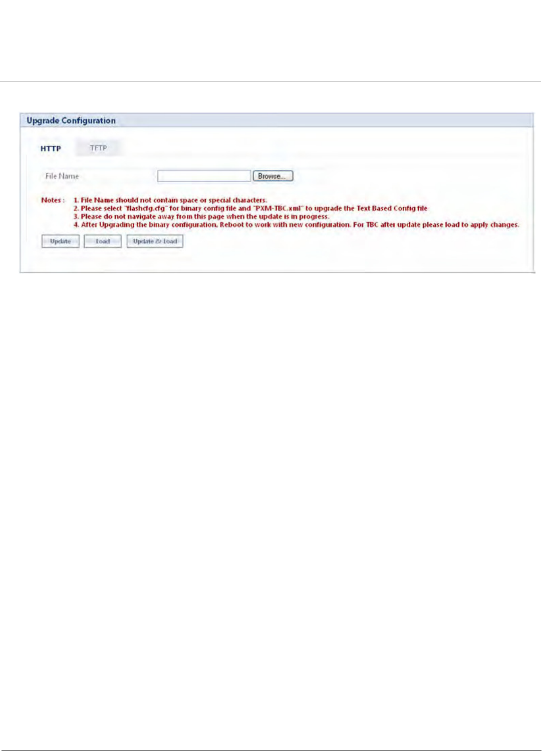
Procedures
Tsunami QB-8100 Series (100 Mbps/5 Mbps Models) Installation and Management Guide 181
Figure 7-6 Update the device with TBC File via HTTP
1. Click Browse and select the TBC file.
2. Click Update to initiate the HTTP Update operation.
3. Click Load to load the TBC file.
Or
4. Click Update & Load to update and load with new configurations immediately.
NOTES:
•Click COMMIT for the changes to take effect.
•After upgrading new configuration, the device must be rebooted.
•To reject the changes done through Update or Update & Load options, reboot the device without clicking
COMMIT.
7.5.5.2 Updating the device with TBC File via TFTP
For updating the device with TBC File via TFTP Server, click MANAGEMENT > File Management > Upgrade Configuration
> TFTP.
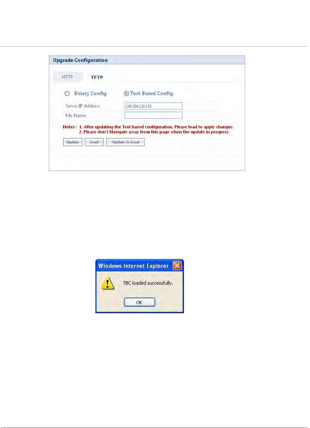
Procedures
Tsunami QB-8100 Series (100 Mbps/5 Mbps Models) Installation and Management Guide 182
Figure 7-7 Update the device with TBC File via TFTP
1. Select the Text Based Config option button.
2. Enter the TFTP Server IP Address.
3. Enter the name of the configuration file to be updated to the device.
•Click Update to initiate the TFTP update operation. Then click Load to apply the updated changes. Finally click
COMMIT for the changes to take effect.
Or
•Click Update & Load to update and load with new configurations, the following window appears.
Figure 7-8 Message Window after successful loading of TBC File
•Click COMMIT for the changes to take effect.
7.5.6 Loading the TBC file
All configurations in the TBC file can be loaded to the device using all the three interfaces (SNMP/WEB/ CLI). The Update,
Load and Update & Load tabs present in the MANAGEMENT > File Management > Upgrade Configuration page are
used to load the TBC file using WEB. To load the TBC file, it should be generated or downloaded to the device.
If the TBC file is not with correct XML syntax, the file will be discarded with DOM error and no configurations will be loaded.
All duplicate values entered are considered as errors while loading and syslogs will be generated accordingly. Therefore, it is
recommended to delete all unchanged parameters from the TBC file during its edition. Commit is required to retain the
configurations across reboots after loading the TBC file.

Procedures
Tsunami QB-8100 Series (100 Mbps/5 Mbps Models) Installation and Management Guide 183
NOTE: Both Commit and Reboot are required to accept the modifications done in the TBC File. Only reboot is required
to reject the modifications.
Loading the TBC file is allowed only once in an active device session (i.e., if TBC file is loaded, reboot is required to apply all
configurations or to load another TBC file). All configurations in the TBC file are loaded to the device irrespective of their
default or modified or added configurations. Loading the TBC file takes approximately 10-20 seconds depending on the
number of configurations added.
NOTE: If you get any time-out errors while loading TBC file from SNMP interface, increase the time-out value to more
than 30 secs in the MIB Browser.
7.6 Soft Reset to Factory Default
The unit can be reset to the factory default settings. Resetting to default settings leads to configuring the unit anew.
To reset to factory default settings using the Web Interface
1. Click Management > Reset for Factory.
2. Click the Reset to Factory Default button.
The device configuration parameter values are reset to their factory default values. If you do not have access to the unit, you
can use the procedure described in Hard Reset to Factory Default as an alternative.
7.7 Hard Reset to Factory Default
If you cannot access the unit or you have lost its password, you can reset the unit to the factory default settings. Resetting to
default settings leads to configuring the unit anew.
To reset to factory default settings, press and hold the RELOAD button on the side of the unit’s power supply for 5 seconds.
The current configuration is deleted from the unit and the unit reboots with factory defaults.
CAUTION: If you hold the RELOAD button for longer than 10 seconds, you may go into Forced Reload mode,
which erases the unit’s embedded software.
7.8 Forced Reload
With Forced Reload, you can erase the embedded software. Use this procedure only as a last resort if the unit does not boot
and the “Reset to Factory Defaults” procedure does not help. If you perform a Forced Reload, you must download a new
firmware with the Bootloader (see “Firmware Download with the Bootloader” below).
CAUTION: The following procedure erases the embedded software of the unit. This software image must be
reloaded through an Ethernet connection with a TFTP server. The image filename to be downloaded
can be configured with ScanTool through the Ethernet interface to make the unit functional again.
To do a forced reload
1. Disconnect and reconnect power to the unit; the unit resets and the LEDs flash.
2. Immediately press and hold the RELOAD button on the side of the unit’s power supply for about 20 seconds. The
software image and configuration are deleted from the unit.
3. Follow the Firmware Download with the Bootloader procedure to download an image file.
NOTE: While performing the hard reset to Factory Defaults / Forced Reload operations on the QB-8100 unit, ensure
that any external device powered through the PoE injector is disconnected to avoid unwanted reload of the external
device.

Procedures
Tsunami QB-8100 Series (100 Mbps/5 Mbps Models) Installation and Management Guide 184
7.9 Upgrade a New Firmware Using ScanTool in Bootloader Mode
To download the unit’s firmware, you will need an Ethernet connection to the computer on which the TFTP server resides and
to a computer that is running ScanTool (this is either two separate computers connected to the same network or a single
computer running both programs).
ScanTool detects if a device does not have a valid software firmware installed. In this case, the TFTP Server and Image File
Name parameters are enabled in the ScanTool’s Change screen so you can download a new firmware to the unit. (These fields
are grayed out if ScanTool does not detect a software firmware problem.)
NOTE: If you are unable to view the configuration parameters in ScanTool, it means that the device is not responding
to your network. Hard reset the unit by unplugging and plugging the Power cable to PoE injector.
7.9.1 Preparing to Download the Firmware
Before starting, you need to know the unit’s IP address, subnet mask, the TFTP Server IP Address, and the unit’s firmware
name. Make sure the TFTP server is running and configured to point to the folder containing the image to be downloaded.
7.9.1.1 Download Procedure
Follow these steps to use ScanTool to download the firmware to a device with a missing firmware:
1. Download the latest software from http://support.proxim.com.
2. Copy the latest software updates to your TFTP server.
3. Launch ScanTool.
4. Highlight the entry for the device you want to update and click Change.
5. Set the IP address type as per your choice, either Static or Dynamic.
Setting IP Addrtype to static:
Set IP Address Type to Static.
– Enter an unused IP address that is valid on your network in the IP Address field. You may need to contact your
network administrator to get this address.
– Enter the network's Subnet Mask in the field provided.
– Enter the network's Gateway IP Address, if necessary. You may need to contact your network administrator to get
this address. You should only enter the default gateway address (169.254.128.132) if the device and the TFTP
server are separated by a router.
– Enter the IP address of your TFTP server in the field provided.
– Enter the Image File Name (including the file extension). Enter the full directory path and file name. If the file is
located in the default TFTP directory, you need to enter only the file name.
Setting IP Addrtype to dynamic:
– Set IP Addrtype to Dynamic.
– Start a tftp server and bootp server and enter all the configuration parameters (ipaddr, subnet mask etc).
6. Click OK. The device will reboot and the download will begin automatically. You should see downloading activity
within the TFTP server's status screen.
7. Click OK when prompted that the device has been updated successfully to return to the Scan List screen.
8. Click Cancel to close the ScanTool.
9. When the download process is complete, configure the device as desired.

Procedures
Tsunami QB-8100 Series (100 Mbps/5 Mbps Models) Installation and Management Guide 185
7.10 Download a New Firmware Using CLI from Bootloader
To download the unit’s Image File, you will need an Ethernet connection to the computer on which the TFTP server resides.
This can be any computer on the LAN or connected to the device with a cross-over Ethernet cable. You must also connect the
device to a computer with a standard serial cable and use a terminal client, such as HyperTerminal. From the terminal, enter
CLI Commands to set the IP address and download unit’s Image.
7.10.1 Preparing to Download the Firmware
Before starting, you need to know the Unit’s IP address, subnet mask, the TFTP Server IP Address, and the UNIT’S firmware
name. Make sure the TFTP server is running and configured to point to the folder containing the firmware to be downloaded.
7.10.1.1 Download Procedure
1. Download the latest software from http://support.proxim.com.
2. Copy the latest software updates to your TFTP server’s default directory.
3. Use a cross-over serial cable to connect the Unit’s serial port to your computer’s serial port.
4. Open your terminal emulation program (like HyperTerminal) and set the following connection properties:
•Com Port: <COM1, COM2, etc., depending on your computer>
•Baud rate: 115200
•Data Bits: 8
•Stop bits: 1
•Flow Control: None
•Parity: None
5. Under File > Properties > Settings > ASCII Setup, enable the Send line ends with line feeds option.
6. HyperTerminal sends a line return at the end of each line of code.
7. Power Reset the device (by resetting the power on PoE injector).
8. The terminal display shows Power On Self Tests (POST) activity. After approximately 30 seconds, a message appears
indicating, “Starting ScanTool interface, press any key to enter CLI 5” and starts a counter for 5 seconds.
9. If the above counter expires, bootloader enters the ScanTool mode. To enter the CLI, press any key before the counter
expires. Now a prompt appears as below:
Bootloader=>
10. Enter only the following statements:
Bootloader=> show (to view configuration parameters and values)
Bootloader=> set ipaddr <device IP Address>
Bootloader=> set serverip <TFTP Server IP Address>
Bootloader=> set filename <Device’s Image File Name, including file extension>
Bootloader=> set gatewayip <Gateway IP Address>
Bootloader=> set netmask <Network Mask>
Bootloader=> set ipaddrtype static
Bootloader=> show (to confirm your new settings)
Bootloader=> reboot
Example:
Bootloader=> show
Bootloader=> set ipaddr 169.254.128.132
Bootloader=> set serverip 169.254.128
Bootloader=> set filename <imagename>

Procedures
Tsunami QB-8100 Series (100 Mbps/5 Mbps Models) Installation and Management Guide 186
Bootloader=> set gatewayip 169.254.128.132
Bootloader=> set netmask 255.255.255.0
Bootloader=> set ipaddrtype static
Bootloader=> show
Bootloader=> reboot
The device will reboot and then download the firmware. You should see the downloading activity within the TFTP server’s
status screen. When the download process is complete, configure the device as desired.
NOTE: If the device is not responding to your network, hard reset the unit by unplugging and plugging the Power
cable to PoE injector.

Tsunami QB-8100 Series (100 Mbps/5 Mbps Models) Installation and Management Guide 187
8
Troubleshooting
This chapter helps you to isolate and solve problems with your QB-8100 unit. If the procedures discussed in this document
does not provide a solution, or the solution does not solve your problem, check our support website at
http://support.proxim.com.
Before you start troubleshooting, check the details in the product documentation. For details about RADIUS, TFTP, terminal
and telnet programs, and Web browsers, refer to their appropriate documentation.
In some cases, rebooting the QB-8100 unit clears the problem. If nothing else helps, consider a Soft Reset to Factory
Default or a Forced Reload. The Forced Reload option requires you to download a new firmware to the QB-8100 unit.
The following topics are covered in this chapter:
•PoE Injector
•Connectivity Issues
•Communication Issues
•Setup and Configuration Issues

Troubleshooting
Tsunami QB-8100 Series (100 Mbps/5 Mbps Models) Installation and Management Guide 188
8.1 PoE Injector
8.1.1 The Unit Does Not Work
1. Verify that you are using a standard UTP Category 5 cable.
2. Try a different port on the same PoE injector hub (remember to move the input port accordingly) – if it works, there is
probably a faulty port or bad RJ-45 port connection.
3. If possible, try to connect the unit to a different PoE injector hub.
4. Try using a different Ethernet cable – if it works, there is probably a faulty connection over the long cable, or a bad
RJ-45 connection.
5. Check power plug and hub.
6. If the Ethernet link goes down, check the cable, cable type, switch, and hub.
8.1.2 There Is No Data Link
1. Verify that the indicator for the port is “on.”
2. Verify that the PoE injector hub is connected to the Ethernet network with a good connection.
3. Verify that the Ethernet cable is Category 5 or better and is less than 100 meters (approximately 325 feet) in length
from the Ethernet source to the QB-8100 unit.
4. Try to connect a different device to the same port on the PoE injector hub – if it works and a link is established, there
is probably a faulty data link in the unit.
5. Try to re-connect the cable to a different output port (remember to move the input port accordingly) – if it works,
there is probably a faulty output or input port in the PoE injector hub or a bad RJ-45 connection.
8.1.3 Overload Indications
1. Verify that you are not using a cross-over cable between the PoE injector output port and the unit.
2. Verify that there is no short over any of the twisted pair cables.
3. Move the device into a different output port (remember to move the input port accordingly); if it works, there is
probably a faulty port or bad RJ-45 connection.
8.2 Connectivity Issues
8.2.1 QB-8100 Does Not Boot
The QB-8100 shows no activity (the power LED is off).
1. Ensure that the power supply is properly working and correctly connected.
2. Ensure that all cables are correctly connected.
3. Check the power source.
4. If you are using an Active Ethernet splitter, ensure that the voltage is correct.
5. If you are using PoE injector, make sure you are using a Category 5, foiled, twisted pair cable to power the unit.
8.2.2 Ethernet Link Does Not Work
1. First check the Ethernet LED:
•Solid Green: Ethernet is up.
•Blinking Green: Ethernet is down.
2. Verify pass-through versus cross-over cable.

Troubleshooting
Tsunami QB-8100 Series (100 Mbps/5 Mbps Models) Installation and Management Guide 189
8.2.3 Serial Link Does Not Work
1. Make sure you are using a standard, straight-through, 9-pin serial cable.
2. Double-check the physical network connections.
3. Make sure your PC terminal program (such as HyperTerminal) is active and configured to the following values:
– Com Port: (COM1, COM2, etc. depending on your computer);
– Baud rate: 115200; Data bits: 8; Stop bits: 1; Flow Control: None; Parity: None;
– Line Feeds with Carriage Returns
(In HyperTerminal select: File > Properties > Settings > ASCII Setup > Send Line Ends with Line Feeds)
8.2.4 Cannot Use the Web Interface
1. Open a command prompt window and enter ping <ip address unit> (for example ping 10.0.0.1). If the unit does not
respond, make sure that you have the correct IP address. If the unit responds, the Ethernet connection is working
properly, continue with this procedure.
2. Ensure that you are using Microsoft Internet Explorer 7.0 (or later) or Firefox 3.0 (or later).
3. Ensure that you are not using a proxy server for the connection with your Web browser.
4. Ensure that you have not exceeded the maximum number of Web Interface or CLI sessions.
5. Double-check the physical network connections. Use a well-known unit to ensure the network connection is properly
functioning.
6. Perform network infrastructure troubleshooting (check switches, routers, and so on).
NOTE: At any point of time, if your device is unable to connect to your network, power reset your device by
unplugging and plugging PoE injector.

Troubleshooting
Tsunami QB-8100 Series (100 Mbps/5 Mbps Models) Installation and Management Guide 190
8.3 Communication Issues
8.3.1 Two Units Are Unable to Communicate Wirelessly
If a wireless link cannot be established after testing the two units within close distance of each other, then there can be two
reasons why wireless connectivity is not possible while the QB-8100 endpoints are at their desired locations:
There may be a problem in the RF path, for example, a bad connector attachment (this is the most common problem in
installations) or a bad cable (water ingress).
NOTE: The cables can be swapped with known good ones as a temporary solution to verify cable quality.
Another reason may be related to an interference problem caused by a high signal level from another radio. This can be
checked by changing the frequency channel and then verifying whether another channel works better or by changing the
polarization as a way of avoiding the interfering signal. To know in advance how much interference is present in a given
environment, a Spectrum Analyzer can be attached to a (temporary) antenna for measuring the signal levels on all available
channels.
NOTE: The antennas are usually not the problem, unless mounted upside down causing the drain hole to quickly fill
the radome with water.
If a wireless link is not established after testing two units within close distance of each other, then the problem is either
hardware or configuration related, such as a wrong Network name, Encryption key, Network Secret or End Point A Station
Name. To eliminate these issues from being a factor, resetting the both units to factory defaults is the recommended solution.
If a wireless link is not possible after resetting the units and verifying that one unit is a End Point A with WORP End Point A
interface configured and the other is an End Point B unit, then the problem is not configuration related and the only
remaining reason is a possible hardware problem. Acquiring a third unit and then testing it amongst the existing units will
help pinpoint the broken unit.
8.3.2 Surge and Lightning preventive maintenance
In case of any lightning or surge occurrence, check for the conditions specified below:
•Check the RF signals by referring to RSSI statistics and if the signal strength has been lowered considerably, replace the
surge arrestor.
•Unscrew the N-Type connector at the top and visually inspect the surge arrestor for electrical burns. If any, replace the
surge arrestor.

Troubleshooting
Tsunami QB-8100 Series (100 Mbps/5 Mbps Models) Installation and Management Guide 191
8.4 Setup and Configuration Issues
The following issues relate to setup and configuration problems.
8.4.1 Lost Password
If you have lost your password, you must reset the QB-8100 device to the default settings. See Hard Reset to Factory Default
The default password is public. If you record your password, keep it in a safe place.
8.4.2 The QB-8100 Responds Slowly
If the QB-8100 takes a long time to become available, it could mean that:
•No DHCP server is available.
•The IP address of the QB-8100 is already in use. Verify that the IP address is assigned only to the QB-8100. Do this by
switching off the QB-8100 and then pinging the IP address. If there is a response to the ping, another device in the
network is using the same IP address. If the QB-8100 uses a static IP address, switching to DHCP mode could remedy
this problem. Also see Setting the IP Address with ScanTool.
•There is too much network traffic.
8.4.3 Device Has Incorrect IP Address
1. Default IP Address Assignment mode is Dynamic. If you do not have a DHCP server on your network, the default IP
Address is 169.254.128.132 for End Point A and 169.254.128.131 for End Point B. If you have more than one unit
with default IP address connected to the network, you will not be able to communicate with them (due to an IP
address conflict). In this case, assign each unit a unique static IP address via the serial cable or turn off all units but one
and change the IP address using ScanTool one at a time.
2. The unit only contacts a DHCP server during boot-up. If your network’s DHCP server is not available while the unit is
booting, the device will use the default IP address (169.254.128.132 for End Point A and 169.254.128.131 for End
Point B). Reboot the unit once your DHCP server is on-line again or use the ScanTool to find the unit’s current IP
address.
3. To find the unit’s current IP address if using DHCP, open the IP Client Table in the DHCP Server and match the unit’s IP
address to its MAC address (found on the product label). Alternatively, use ScanTool to identify the unit’s current IP
address.
4. Once you have the current IP address, use the HTTP or CLI Interface to change the unit’s IP settings, if necessary.
5. If you use static IP Address assignments and cannot access the unit over Ethernet, follow the Initializing the IP Address
using CLI procedure. Once the IP Address is set, you can use the Ethernet Interface to complete configuration. If the
device contains the default or known IP and is not accessible, then you need to check the Management VLAN
configuration.
6. Configure the device to “DHCP” mode and reboot. While bootup, if there is a DHCP Server on the network, the DHCP
Server will assign an IP Address to the unit.
8.4.4 HTTP Interface Does Not Work
1. Make sure you are using a compatible browser:
– Microsoft Internet Explorer 7.0
– Mozilla Firefox 3.0 and later.
2. Make sure you have the proper IP address. Enter your unit’s IP Address in the browser address bar, similar to this
example: http://192.168.1.100. When the Enter Network Password window appears, enter the User Name and enter
the HTTP password in the Password field. The default HTTP username is admin and password is public.
3. Use the CLI over the serial port to check the IP Access Table, which may be restricting access to HTTP.

Troubleshooting
Tsunami QB-8100 Series (100 Mbps/5 Mbps Models) Installation and Management Guide 192
8.4.5 Telnet CLI Does Not Work
1. Make sure you have the proper IP Address. Enter your device IP address in the Telnet connection dialog, from a DOS
prompt, type: C:\> telnet <Device IP Address>
2. Use the CLI over the serial port to check the IP Access Table, which may be restricting access to Telnet and HTTP.
8.4.6 TFTP Server Does Not Work
With TFTP, you can transfer files to and from the QB-8100 device. Also see TFTP Server Setup. If a TFTP server is not
properly configured and running, you cannot upload and download files.
The TFTP server:
•Can be situated either local or remote
•Must have a valid IP address
•Must be set for send and receive without time-out
•Must be running only during file upload and download
If the TFTP server does not upload or download files, it could mean:
•The TFTP server is not running
•The IP address of the TFTP server is invalid
•The upload or download directory is not correctly set
•The file name is not correct
8.4.7 Setting IP Address using Serial Port
Use the following procedure to set an IP address over the serial port using the CLI. The network administrator typically
provides the device IP address.
8.4.7.1 Hardware and Software Requirements
•Standard cross-over serial data (RS-232) cable (not included with shipment).
•ASCII Terminal software, such as HyperTerminal.
8.4.7.2 Attaching the Serial Port Cable
1. Connect one end of the serial cable to the unit and the other end to a serial port on your computer.
2. Power on the computer and unit, if necessary.
8.4.7.3 Initializing the IP Address using CLI
After installing the serial port, you may use the CLI to communicate with the device. CLI supports most generic terminal
emulation programs, such as HyperTerminal (which is included with the Windows operating systems). In addition, many web
sites offer shareware or commercial terminal programs you can download. Once the IP address has been assigned, you can
use the HTTP interface or the CLI over Telnet to complete the configuration.
Follow these steps to assign the QB-8100 unit an IP address:
1. Open your terminal emulation program (like HyperTerminal) and set the following connection properties:
•Com Port: <COM1, COM2, etc., depending on your computer>
•Baud rate: 115200
•Data Bits: 8
•Stop bits: 1
•Flow Control: None

Troubleshooting
Tsunami QB-8100 Series (100 Mbps/5 Mbps Models) Installation and Management Guide 193
•Parity: None
2. Press the REBOOT button on the PoE injector of the unit.
The terminal display shows Power On Self Tests (POST) activity, displays the software version, and prompts to enter the CLI
username and password similar to the example below. This process may take up to 90 seconds.
#################################################|
# Version: 2.5.0 B305010
# Architecture: PowerPC 8313
# Creation: On May 1 2010 At 15:41:28
#################################################|
Username: admin
Password:
3. Enter the CLI Username and password (default username is admin and password is public). The terminal displays a
welcome message and then the CLI Prompt:
System Name>
4. Enter show configure network to find the current IP address of the device.
5. Change the IP address and other network values using the following CLI commands, similar to the example below (use
your own IP address and subnet mask).
System Name> enable
System Name# configure
System Name(config)#network
System Name(config-net)# ip
System Name(config-net-ip)# ethernet-ip-table
System Name(config-net-ip-etherip)# rowedit 1 ipaddress <ipaddress>
System Name(config-net-ip-etherip)# rowedit 1 mask <subnet mask>
System Name(config-net-ip-etherip)# rowedit 1 address-type <Address Type>
System Name(config-net-ip)# default-gateway <IP Gateway>
System Name(config-net-ip-etherip)#exit
System Name(config-net-ip)#exit
System Name(config-net)#exit
System Name(config)# commit 1
System Name(config)# reboot 1
6. After the unit reboots, verify the new IP address by reconnecting to the CLI and enter a show configure network
command. Alternatively, you can ping the device from a network computer to confirm that the new IP address has
taken effect.
7. When the proper IP address is set, use the HTTP interface or CLI over Telnet to configure the rest of the unit’s operating
parameters.

Troubleshooting
Tsunami QB-8100 Series (100 Mbps/5 Mbps Models) Installation and Management Guide 194
8.4.8 RADIUS Authentication Server
If you enabled RADIUS Authentication on the unit, make sure that your network’s RADIUS servers are operational. Otherwise,
clients cannot log in. There are several reasons the authentication server services might be unavailable, here are two typical
things to check:
•Make sure you have the proper RADIUS authentication server information setup configured in the device. Check the
RADIUS Authentication Server’s Shared Secret and Destination Port number (default is 1812; for RADIUS Accounting,
the default is 1813).
•Make sure the RADIUS authentication server RAS setup matches the device.
8.4.9 TFTP Server
The “Trivial File Transfer Protocol” (TFTP) server allows you to transfer files across a network. You can upload the configuration
files from the unit for backup or copying, and you can download configuration files or new firmware. The TFTP software is
located on the installation CD. If a TFTP server is not configured and running, you will not be able to download and upload
software and configuration files to/from the device. Remember that the TFTP server does not have to be local, so long as you
have a valid TFTP IP address. Note that you do not need a TFTP server running unless you want to transfer files to or from the
device.
After the TFTP server is installed:
•Check to see that TFTP is configured to point to the directory containing the device Image.
•Make sure you have the proper TFTP server IP Address, the proper device firmware name, and that the TFTP server is
connected.
•Make sure the TFTP server is configured to both Transmit and Receive files (on the TFTP server’s Security tab), with no
automatic shutdown or time-out (on the Auto Close tab).
8.4.10 Recovery Procedures
The most common installation problems relate to IP addressing. For example, without the TFTP server IP Address, you will not
be able to download a new device firmware to the unit. IP Address management is fundamental. We suggest you to create a
chart to document and validate the IP addresses for your system. If the password is lost or forgotten, you will need to reset
the unit to default values. The Soft Reset to Factory Defaults and Hard Reset to Factory Defaults procedures reset
configuration settings, but do not change the current device firmware.
If the device has a corrupted firmware, follow the Forced Reload procedure to erase the current AP Image and download a
new firmware.
8.4.11 Soft Reset to Factory Defaults
Use this procedure to reset the network configuration values, including the password, IP address, and subnet mask. The
current unit Image is not deleted.
1. Click Management > Reset to Factory.
2. Click Reset to Factory Default. The device is reset to its factory default state.
3. The default IP address that the unit resets to is 169.254.128.132 for End Point Athe device and 169.254.128.131 for
End Point B. If you want to make modification to the IP address setting, use the ScanTool or CLI. See Using CLI to
Manage the Access Point for CLI information.
If you do not have access to the HTTP or CLI interfaces, use the procedure described in Hard Reset to Factory Defaults.
8.4.12 Hard Reset to Factory Defaults
If you cannot access the unit or you have lost its password, you can reset the unit to the factory default settings. Resetting to
default settings leads to configuring the unit anew.

Troubleshooting
Tsunami QB-8100 Series (100 Mbps/5 Mbps Models) Installation and Management Guide 195
To reset to factory default settings, press and hold the RELOAD button on the side of the unit’s PoE injector power supply for
5 seconds. The current configuration is deleted from the unit and the unit reboots, with factory defaults.
CAUTION: It you hold the RELOAD button for longer than 10 seconds, you may go into Forced Reload mode, which
erases the unit’s embedded software.
8.4.13 Forced Reload
With Forced Reload, you bring the unit into bootloader mode by erasing the embedded software. Use this procedure only as
a last resort if the unit does not boot and the procedure did not help.
CAUTION: By completing this procedure, the embedded software in the unit will be erased. You will need to reload the
software before the unit is operational.
To do a forced reload
1. Reset the unit by resetting the power plug of PoE injector.
2. Press and hold the RELOAD button which is located on the PoE injector for about 20 seconds. The unit deletes the
current firmware.
3. Unit will try to load the required firmware using the default factory configuration parameters. If this fails, then it will
enter either CLI mode or ScanTool mode as per the user’s choice, with a message on the serial console “Starting
ScanTool interface, press any key to enter CLI 5”. Follow one of the procedures below to load a new firmware to the
unit:
•Download a New Image Using ScanTool
•Download a New Image Using the Bootloader CLI
Because the CLI option requires a physical connection to the unit’s serial port, Proxim recommends the ScanTool Option.
8.4.14 VLAN Operation Issues
The correct VLAN configuration can be verified by “pinging” both wired and wireless hosts from both sides of the device and
the network switch. Traffic can be “sniffed” on the wired (Ethernet), if configured. Bridge frames generated by wireless
clients and viewed on one of the backbones should contain IEEE 802.1Q compliant VLAN headers or tags. The VLAN ID in the
headers should correspond to one of the VLAN User IDs configured for the unit.
The correct VLAN assignment can be verified by pinging:
•The unit to ensure connectivity
•The switch to ensure VLAN properties This should be checking not pinging
•Hosts past the switch to confirm the switch is functional
Ultimately, traffic can be “sniffed” on the Ethernet interface using third-party packages. Most problems can be avoided by
ensuring that 802.1Q compliant VLAN tags containing the proper VLAN ID have been inserted in the bridged frames. The
VLAN ID in the header should correspond to the assigned VLAN.
What if network traffic is being directed to a nonexistent host?
•All sessions are disconnected, traffic is lost, and a manual override is necessary.
•Workaround: You can configure the switch to mimic the nonexistent host.
I have just configured the Management ID and now I can't manage the device.
•Check to ensure your password is correct. If your password is incorrect or all inbound packets do NOT have the correct
tag, then a Forced Reload is necessary.
CAUTION: The Forced Reload procedure disconnects all users and resets all values to factory defaults.

Troubleshooting
Tsunami QB-8100 Series (100 Mbps/5 Mbps Models) Installation and Management Guide 196
8.4.15 Changes Do Not Take Effect
Changes made in the Web Interface do not take effect:
1. Restart your Web browser.
2. Log into the radio unit again and make changes.
3. Reboot the radio unit when prompted to do so.
4. Click Commit for the changes to take effect.
Wait until the reboot is completed before accessing the unit again.
8.4.16 Link Problems
While wireless networking emerges more and more, the number of wireless connections to networks grows every day. To
successfully use the connections, technicians must be able to troubleshoot the system effectively. This section gives hints on
how a point-to-point network could be analyzed in the case of “no link”, a situation in which the customer thinks that the
link is down because there is no traffic being passed.
The four general reasons that a wireless link may not work are related to:
•Hardware
•Configuration
•Path issues (such as distance, cable loss, obstacles)
•Environment (anything that is outside the equipment and not part of the path itself)
You have tested the equipment in the office and have verified that the hardware and configurations are sound. The path
calculation has been reviewed, and the path has been double-checked for obstacles and canceling reflections. Still, the user
reports that the link does not work.
Most likely, the problem reported is caused by the environment or by improper tests to verify the connection. The test
method, cabling, antennas, and antenna alignment have been checked. Always do this before checking the environment.
8.4.17 General Check
Two general checks are recommended before taking any action:
•Check whether the software version on all devices is the most current version.
•Check for any reported alarm messages in the Event Log.
8.4.18 Statistics Check
Interference and other negative environment factors always have an impact on the number of correctly received frames. The
Tsunami QB-8100 models give detailed information about transmission errors in the Web interface, under Monitor
(Section/Window etc.).
The windows that are important for validating the health of the link are:
•Monitor / Wireless Statistics: Check CRC errors: Rising CRC errors indicate interference or low fade margin. So does
Failed count. If only one of those is high, this indicates that a source of interference is significant near one end of the
link.
•Monitor / Ethernet Statistics: The information is given after the wireless Ethernet frame is converted into a normal
Ethernet frame. The parameters shown are part of the MIB-II.
– Both operational and admin status should be up. An admin status of down indicates that the interface is configured
to be down.
– In Discards and Out Discards indicate overload of the buffers, likely caused by network traffic, which is too heavy.

Troubleshooting
Tsunami QB-8100 Series (100 Mbps/5 Mbps Models) Installation and Management Guide 197
– In Errors and Out Errors should never happen; however, it might happen if a frame’s CRC was correct while the
content was still invalid.
•Monitor / Wireless / WORP (Statistics on WORP): WORP runs on top of normal Ethernet, which means that the WORP
frame is in fact the data field of the Ethernet frame. Send Failure or Send Retries must be low in comparison to Send
Success. Low is about 1%. The same applies for Receive Success versus Receive Retries and Receive Failures. Note that
the Receive Failures and Retries can be inaccurate. A frame from the remote site might have been transmitted without
even being received; therefore, the count of that frame might not have been added to the statistics and the receiver
simply could not know that there was a frame.
– Remote Partners indicates how many End Point B units are connected (in case of an End Point A) or whether an End
Point A is connected (in case of an End Point B).
8.4.19 Analyzing the Spectrum
The ultimate way to discover whether there is a source of interference is to use a spectrum analyzer. Usually, the antenna is
connected to the analyzer when measuring. By turning the antenna 360 degrees, one can check from which direction the
interference is coming. The analyzer will also display the frequencies and the level of signal is detected. Proxim recommends
performing the test at various locations to find the most ideal location for the equipment.
8.4.19.1 Avoiding Interference
When a source of interference is identified and when the level and frequencies are known, the next step is to avoid the
interference. Some of the following actions can be tried:
•Changing the channel to a frequency away from the interference is the first step in avoiding interference. The installer
can select a DFS Preferred Channel.
•Each antenna has a polarization; try to change to a polarization different from the interference.
•A small beam antenna looks only in one particular direction. Because of the higher gain of such an antenna, lowering
the output power or adding extra attenuation might be required to stay legal. This solution cannot help when the
source of interference is right behind the remote site.
•Lowering the antennas can help avoid seeing interference from far away.
Move the antennas to a different location on the premises. This causes the devices to look from a different angle, causing a
different pattern in the reception of the signals. Use obstructions such as buildings, when possible, to shield from the
interference.
8.4.19.2 Conclusion
A spectrum analyzer can be a great help to identify whether interference might be causing link problems on Tsunami
QB-8100 devices.
Before checking for interference, the link should be verified by testing in an isolated environment, to make sure that the
hardware works and your configurations are correct. The path analysis, cabling and antennas should be checked as well.
Statistics in the web interface under Monitor indicates if there is a link, if the link is healthy, and a continuous test can be
done using the Link Test.
– Base Announces should increase continuously.
– Registration Requests and Authentication Requests should be divisible by 3. WORP is designed in a way that each
registration sequence starts with 3 identical requests. It is not a problem if, once in a while, one of those requests is
missing. Missing requests frequently is to be avoided.
•Monitor / Per Station (Information per connected remote partner): Check that the received signal level (RSL) is the
same on both sides. This should be the case if output power is the same. Two different RSLs indicate a broken
transmitter or receiver. A significant difference between Local Noise and Remote Noise could indicate a source of
interference near the site with the highest noise. Normally, noise is about –80 dBm at 36 Mbps. This number can vary
from situation to situation, of course, also in a healthy environment.

Troubleshooting
Tsunami QB-8100 Series (100 Mbps/5 Mbps Models) Installation and Management Guide 198
•Monitor / Link Test (Information used by Administrators for on-the-spot checking): Check the received signal level (RSL)
and noise level. Compare the RSL with the values from path analysis. If the figures differ significantly from the values
recorded at the Per Station window, check for environment conditions that change over time.

Tsunami QB-8100 Series (100 Mbps/5 Mbps Models) Installation and Management Guide 199
A
Frequency Domains and Channels
Introduction
The Tsunami QB-8100 is available in two SKUs one for US (US) and the other for World (WD) Markets. Depending on the
SKU, the device is hard programmed at factory to that Regulatory domain. Regulatory domain controls the list of frequency
domains that are available in that SKU. Further each frequency domain will define the country specific retaliatory rules and
frequency bands. This is a configurable option.
The frequency domain can be easily configured using the WEB Interface as it is a drop down list with all the available
domains. When using with CLI/SNMP, care has to be taken to set the domains using a predefined ENUM value. Below is the
list of all available frequency domains in each SKU with their corresponding ENUM value in the braces:
For US SKU
•United States 5 GHz (1)
•United States 5.8 GHz (2)
•United States2 5.3, 5.8 GHz (22)
For World SKU
•World 5 GHz (4)
•World 5.9 GHz (21)
•World 4.9 GHz (5)
•Canada 5 GHz (9)
•Europe 5.8 GHz (10)
•Europe 5.4 GHz (11)
•Russia 5 GHz (13)
•Taiwan 5 GHz (14)
•United States 5 GHz (15)
•Canada 5.8 GHz (16)
•India 5.8 GHz (23)
•UK 5.8 GHz (20)

Frequency Domains and Channels
Tsunami QB-8100 Series (100 Mbps/5 Mbps Models) Installation and Management Guide 200
The following screen displays the list of frequency domains supported by the device.
NOTE: The supported frequency domains differ based on the License file present on the board.
T8000-C1:65:7E# show supported-frequency-domains
RADIO-INDEX 1
SUPPORTED FREQUENCY DOMAINS : 4,9,10,11,13,14,15,16,20,23
********************************************************
Frequency Domains Reference List
********************************************************
1 ---> United States 5GHz
2 ---> United States 5.8GHz
3 ---> United States 2.4GHz
4 ---> World 5GHz
5 ---> World 4.9GHz
6 ---> World 2.4GHz
7 ---> World 2.3GHz
8 ---> World 2.5GHz
9 ---> Canada 5GHz
10 ---> Europe 5.8GHz
11 ---> Europe 5.4GHz
12 ---> Europe 2.4GHz
13 ---> Russia 5GHz
14 ---> Taiwan 5GHz
15 ---> United States 5GHz
16 ---> Canada 5.8GHz
17 ---> World 6.4GHz
20 ---> UK 5.8GHz
21 ---> World 5.9GHz
22 ---> US2 5.3 And 5.8GHz
23 ---> India 5.8GHz
********************************************************

Frequency Domains and Channels
Tsunami QB-8100 Series (100 Mbps/5 Mbps Models) Installation and Management Guide 201
5 GHz Channels/Frequencies by Country
Frequency
Domain
Frequency
Band
(Start Center
Frequency ~
End Center
Frequency in
MHz)
DFS Allowed Channels (Center Frequency)
5 MHz
10 MHz 20 MHz 40 PLUS
MHz
40 MINUS
MHz
United
States 5
GHz
5260 ~ 5320
5500 ~ 5700
5745 ~ 5825
DFS,
DFS,
Non-DFS
Not
Supported
Not
Supported
52(5260),
53(5265)....
63(5315),
64(5320).
100(5500),
101(5505)..
139(5695),
140(5700).
149(5745),
150(5750)...
164(5820),
165(5825).
52(5260),
53(5265)...
63(5315),
64(5320).
100(5500),
101(5505)....
139(5695),
140(5700).
149(5745),
150(5750)....
160(5800),
161(5805).
56(5280),
57(5285)....
63(5315),
64(5320).
100(5500),
101(5505)....
139(5695),
140(5700).
149(5745),
150(5750)....
164(5820),
165(5825).
United
States 5.8
GHz
5745 ~ 5825 Non-DFS Not
Supported
Not
Supported
149(5745),
150(5750)...
164(5820),
165(5825).
149(5745),
150(5750)...
160(5800),
161(5805).
153(5765),
154(5770)....
164(5820),
165(5825).
United
States2 (5.3,
5.8 GHz)
5260 ~ 5320
5745 ~ 5825
DFS
Non-DFS
Not
Supported
Not
Supported
52(5260),
53(5265)....
63(5315),
64(5320).
149(5745),
150(5750)...
164(5820),
165(5825).
52(5260),
53(5265)....
63(5315),
64(5320).
149(5745),
150(5750)...
160(5800),
161(5805).
56(5280),
57(5285)....
63(5315),
64(5320).
149(5745),
150(5750)...
164(5820),
165(5825).
World 5
GHz
5155 ~ 6075 Non-DFS 31(5155),
32(5160)....
214(6070),
215(6075).
31(5155),
32(5160)....
214(6070),
215(6075).
32(5160),
33(5165)....
213(6065),
214(6070).
32(5160),
33(5165)....
209(6045),
210(6050).
36(5180),
37(5185)....
213(6065),
214(6070).
WORLD 4.9
GHz
4945 ~ 4985 Non-DFS 10 (4945),
20 (4950)....
80 (4980),
90 (4985).
10 (4945),
20 (4950)....
80 (4980),
90 (4985).
20(4950),
30(4955)....
70(4975),
80(4980).
20(4950),
30(4955),
40(4960).
60(4970),
70(4975),
80(4980).
WORLD 5.9
GHz
5880 ~ 5920 Non-DFS 176(5880),
177(5885).....
183(5915),
184(5920).
176(5880),
177(5885)....
183(5915),
184(5920).
177(5885),
178(5890)...
182(5910),
183(5915).
177(5885),
178(5890),
179(5895).
181(5905),
182(5910),
183(5915).

Frequency Domains and Channels
Tsunami QB-8100 Series (100 Mbps/5 Mbps Models) Installation and Management Guide 202
CANADA 5
GHz
5255 ~ 5325
5495 ~ 5585
5655 ~ 5705
DFS 51(5255),
52(5260)....
64(5320),
65(5325).
99(5495),
100(5500)...
116(5580)
117(5585).
131(5655),
132(5660)....
140(5700),
141(5705).
52(5260),
53(5265).....
63(5315),
64(5320).
100(5500),
101(5505).....
115(5575),
116(5580).
132(5660),
133(5665)....
139(5695),
140(5700).
52(5260),
53(5265).....
63(5315),
64(5320).
100(5500),
101(5505)...
115(5575),
116(5580).
132(5660),
133(5665)...
139(5695),
140(5700).
52(5260),
53(5265) .....
63(5315),
64(5320).
100(5500),
101(5505)....
115(5575),
116(5580).
132(5660),
133(5665)....
135(5675),
136(5680).
56(5280),
57(5285)....
63(5315),
64(5320).
100(5500),
101(5505)....
115(5575),
116(5580).
132(5660),
133(5665)....
139(5695),
140(5700).
EUROPE
5.4 GHz
5500 ~ 5700 DFS Not
Supported
100(5500),
101(5505)....
115(5575),
116(5580).
132(5660),
133(5665)....
139(5695),
140(5700).
100(5500),
101(5505)...
115(5575),
116(5580).
132(5660),
133(5665)...
139(5695),
140(5700).
100(5500),
101(5505)...
115(5575),
116(5580).
132(5660),
133(5665)...
135(5675),
136(5680).
104(5520),
105(5525)...
115(5575),
116(5580).
132(5660),
133(5665)...
139(5695),
140(5700).
EUROPE
5.8 GHz
5735 ~ 5870 DFS Not
Supported
147(5735),
148(5740)...
173(5865),
174(5870).
149(5745),
150(5750)...
172(5860),
173(5865.
149(5745),
150(5750)…
168(5840),
169(5845).
153(5765),
154(5770)....
172(5860),
173(5865).
RUSSIA
5 GHz
5155 ~ 6075 Non-DFS 31(5155),
32(5160)....
214(6070),
215(6075).
31(5155),
32(5160).....
214(6070),
215(6075).
32(5160),
33(5165)....
213(6065),
214(6070).
32(5160),
33(5165).....
219(6045),
210(6050).
36(5180),
37(5185).....
213(6065),
214(6070).
Taiwan 5
GHz
5495 ~ 5705
5740 ~ 5810
DFS 99(5495),
100(5500)....
140(5700),
141(5705).
148(5740),
149(5745)....
161(5805),
162(5810).
100(5500),
101(5505)...
139(5695),
140(5700).
149(5745),
150(5750)....
160(5800),
161(5805).
100(5500),
101(5505)...
139(5695),
140(5700).
149(5745),
150(5750)...
160(5800),
161(5805).
100(5500),
101(5505)....
139(5695),
140(5700).
149(5745),
150(5750)....
156(5780),
157(5785).
104(5520),
105(5525)...
139(5695),
140(5700).
149(5745),
150(5750)...
160(5800),
161(5805).
Frequency
Domain
Frequency
Band
(Start Center
Frequency ~
End Center
Frequency in
MHz)
DFS Allowed Channels (Center Frequency)
5 MHz
10 MHz 20 MHz 40 PLUS
MHz
40 MINUS
MHz

Frequency Domains and Channels
Tsunami QB-8100 Series (100 Mbps/5 Mbps Models) Installation and Management Guide 203
NOTE: While choosing a 40MHz bandwidth, you can select 40 PLUS or 40 MINUS. 40 PLUS means the center
frequency calculation is to be done for 20MHz and add another 20MHz to the top edge of 20MHz. 40 MINUS means
the center frequency calculation is to be done for 20MHz and add another 20MHz to the bottom edge of 20MHz.
Details for 40MHz Bandwidth
For 40 PLUS
•2.4GHz -> Channel 1 = 2412MHz.
•Bandwidth starts from 2403 and ends at 2442
•5GHz -> Channel 52 = 5260
•Bandwidth starts from 5251 and ends at 5290
For 40 MINUS
•2.4GHz -> Channel 5 = 2432MHz.
•Bandwidth starts from 2403 and ends at 2442
•5GHz -> Channel 56 = 5280
•Bandwidth starts from 5251 and ends at 5290
India 5.8
GHz
5830 ~ 5870 Non-DFS 166(5830),
167(5835)...
173(5865),
174(5870).
166(5830),
167(5835)....
173(5865),
174(5870).
167(5835),
168(5840)...
172(5860),
173(5865).
167(5835),
168(5840),
169(5845).
171(5855),
172(5860),
173(5865).
CANADA
5.8 GHz
5735 ~ 5855 Non-DFS 147(5735),
148(5740)....
170(5850),
171(5855).
147(5735),
148(5740).....
170(5850),
171(5855).
148(5740),
149(5745)...
169(5845),
170(5850).
148(5740),
149(5745)...
165(5825),
166(5830).
152(5760),
153(5765)...
169(5845),
170(5850).
U.K
5.8 GHz
5735 ~ 5835 DFS Not
Supported
147(5735),
148(5740).....
156(5780),
157(5785),
167(5835).
147(5735),
148(5740)...
156(5780),
157(5785),
167(5835).
147(5735),
148(5740)...
153(5765),
154(5770).
151(5755),
152(5760)....
156(5780),
157(5785),
167(5835).
Frequency
Domain
Frequency
Band
(Start Center
Frequency ~
End Center
Frequency in
MHz)
DFS Allowed Channels (Center Frequency)
5 MHz
10 MHz 20 MHz 40 PLUS
MHz
40 MINUS
MHz

Tsunami QB-8100 Series (100 Mbps/5 Mbps Models) Installation and Management Guide 204
B
Boot Loader CLI and ScanTool
Boot Loader CLI
The Boot Loader CLI is a minimal subset of the normal CLI used to perform initial configuration of the unit. The Boot Loader
CLI is available when the unit’s embedded software is not running.
This interface is only accessible through the serial interface, if:
•The device does not contain a software image
•An existing image is corrupted
•An automatic (default) download of image over TFTP has failed.
The Boot Loader CLI provides you with the ability to configure the initial setup parameters; and depending on this
configuration, a software file is downloaded to the device during startup.
The Boot Loader CLI supports the following commands:
•factory_reset: Restore the factory settings
•help: Print Online Help
•reboot: Reboot the device
•set: Set the parameters
•show: Show the parameters
The Boot Loader CLI supports the following parameters (for viewing and modifying):
•ipaddr: IP Address
•systemname: System Name
•gatewayip: Gateway IP Address
•serverip: Server IP Address
•ipaddrtype: IP Address Type
•netmask: Net Mask
•filename: Image file name (including the file extension)
If the Boot Loader fails to load the firmware from flash, it tries to get the firmware from the network. The default
configuration of the Boot Loader parameters are as follows:
Parameter Value
ipaddr 169.254.128.132
netmask 255.255.255.0
gatewayip 169.254.128.132
systemname systemname
serverip 169.254.128.133
filename imagename
ipaddrtype dynamic
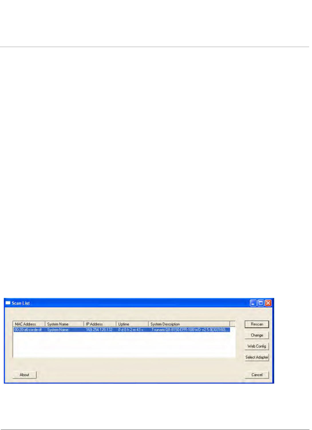
Boot Loader CLI and ScanTool
Tsunami QB-8100 Series (100 Mbps/5 Mbps Models) Installation and Management Guide 205
To Load the Firmware from the Network
•Use the show command to view the parameters and their values and use the set command to set the values to the
parameters as per the requirement.
To Get the IP Parameters Dynamically for Loading the Firmware
1. Set the ipaddrtype to dynamic.
2. Run the BOOTP and TFTP Servers along with a reboot of the unit.
When the device reboots, the device gets the IP Address and Boot filename from the BOOTP server. You need not change any
of the above parameters. After BOOTP succeeds, the device initiates a TFTP request with the filename it gets from BOOTP.
To Load the Firmware by Using Static IP Parameters
1. Use the set command to set the IP parameters like ‘ipaddr’, ‘serverip’, ‘filename’ and also set the parameter
‘ipaddrtype’ to static.
2. Run the TFTP Server along with a reboot of the unit.
When the device reboots, the TFTP request is initiated with the value taken from the parameter “filename”. This request is
sent to the IP address set to the parameter "serverip”. In this case, the TFTP Server should be reachable to the device.
ScanTool
If you want to access the device with Scantool, then the host running the ScanTool should also be in the same network as the
device. The ScanTool broadcast requests are discarded by the routers if the device and the host running the ScanTool are in
different network. This means that the ScanTool cannot discover the device.
A device in Boot Loader can be recognized by looking at the system description. If the system description does not contain
any build number in braces, conclude that the device is in Boot Loader mode.
For example:
Tsunami QB-8100 End Point is the name of the board
WD is the Regulatory Domain
V2.5.0 is the Firmware Version
303160 is the firmware build number
Figure B-1 Scan Tool View of a Device in Boot Loader Mode

Tsunami QB-8100 Series (100 Mbps/5 Mbps Models) Installation and Management Guide 206
C
Technical Specifications
This chapter provides information on the following topics:
•Part Numbers
•Regulatory Approval and Frequency Domains
•Integrated Dual Polarized Panel Antenna Specifications
•Radio and Transmission Specifications
•OFDM Modulation Rates
•Wireless Protocol
•Interfaces
•Transmit Power Settings
•Receive Sensitivity
•Latency
•Management
•Power Supply
•LEDs
•Software Features
•Hardware Specifications
•Physical and Environmental Specifications
•MTBF and Warranty

Technical Specifications
Tsunami QB-8100 Series (100 Mbps/5 Mbps Models) Installation and Management Guide 207
Part Numbers
QB-8100 Series Units
Accessories
Model # CPN # Description
QB-8150-LNK-5-US 902-00011 Tsunami QB 8150 Link, 5 Mbps, MIMO 2x2, 16 dBi Integrated antenna –
US SKU
QB-8150-LNK-5-WD 902-00013 Tsunami QB 8150 Link, 5 Mbps, MIMO 2x2, 16 dBi Integrated antenna –
World SKU
QB-8150-LNK-100-US 902-00019 Tsunami QB 8150 Link, 100 Mbps, MIMO 2x2, 16 dBi Integrated antenna –
US SKU
QB-8150-LNK-100-WD 902-00021 Tsunami QB 8150 Link, 100 Mbps, MIMO 2x2, 16 dBi Integrated antenna –
World SKU
CPN # Description
77537 Universal Mounting Bracket for Wall Mounting
74962 PoE Injector with Reload function

Technical Specifications
Tsunami QB-8100 Series (100 Mbps/5 Mbps Models) Installation and Management Guide 208
Regulatory Approval and Frequency Domains
•Safety Standards: UL 60950, CAN/CSA-C22.2 No. 60950, IEC 60950, EN 60950
•Regulatory Certifications: FCC, IC and ETSI
5 GHz Channels/Frequencies
Region/
Country
Frequency
Domain
Frequency
Band
(Start Center
Frequency ~
End Center
Frequency in
MHz)
No. of Channels
5 MHz 10 MHz 20 MHz 40 PLUS
MHz
40 MINUS
MHz
North
America
United States 5 GHz 5260 ~ 5320
5500 ~ 5700
5745 ~ 5825
Not
Supported
Not
Supported
Up to 71 Up to 67 Up to 67
United States 5.8
GHz
5745 ~ 5825 Not
Supported
Not
Supported
Up to 17 Up to 13 Up to 13
United States2 (5.3,
5.8 GHz)
5260 ~ 5320
5745 ~ 5825
Not
Supported
Not
Supported
Up to 30 Up to 26 Up to 26
Canada 5 GHz 5255 ~ 5325
5495 ~ 5585
5655 ~ 5705
Up to 45 Up to 39 Up to 39 Up to 35 Up to 35
Canada 5.8 GHz 5735 ~ 5855 Upto 25 Up to 25 Up to 23 Up to 19 Up to 19
EU
Countries
Eroupe 5.8 GHz 5.740 ~ 5.865 Up to 7 Up to 3 Up to 3
Europe 5.4 GHz 5500 ~ 5700 Not
Supported
Up to 26 Up to 26 Up to 22 Up to 22
Europe 5.8 GHz 5735 ~ 5870 Not
Supported
Up to 28 Up to 25 Up to 21 Up to 21
Russia 5 GHz 5155 ~ 6075 Up to 185 Up to 185 Up to 183 Up to 179 Up to 179
APAC Taiwan 5 GHz 5495 ~ 5810 Up to 58 Up to 54 Up to 54 Up to 50 Up to 50
India 5.8 GHz 5830 ~ 5870 Up to 9 Up to 9 Up to 7 Up to 3 Up to 3
World World 5 GHz 5155 ~ 6075 Up to 185 Up to 185 Up to 183 Up to 179 Up to 179
World 4.9 GHz 4945 ~ 4985 Up to 63 Up to 63 Up to 43 Up to 3 Up to 3
World 5.9 GHz 5880 ~ 5920 Up to 9 Up to 9 Up to 7 Up to 3 Up to 3
United States 5 GHz 5260 ~ 5825 Not
Supported
Not
Supported
Up to 71 Up to 67 Up to 67
UK 5.8 GHz 5735 ~ 5835 Not
Supported
Up to 12 Up to 11 Up to 8 Up to 8

Technical Specifications
Tsunami QB-8100 Series (100 Mbps/5 Mbps Models) Installation and Management Guide 209
Integrated Dual Polarized Panel Antenna Specifications
Radio and Transmission Specifications
Feature Specification
Vertical Antenna Horizontal Antenna
Frequency band 5.300 – 6.100 GHz
Gain 15 - 16 dBi 15 - 16 dBi
Horizontal Half Power Beam width 17.6 – 20.3 16.5 – 18.3
Vertical Half Power Beam width 16.1 - 20.5 17.0 - 24.0
Sidelobes level -10 dB (Max) -8 dB (Max)
Front-to-back-ratio 23 dB (Max)
Polarization Linear, Vertical Linear, Horizontal
Port to port isolation 27 dB (Min.)
Power Handling 6 W (cw)
VSWR 2.0:1 (Max)
Cable RG178, 150 mm x 2
Connector MMCX R/A Plug
Standard Compliance ETSI TS3, TS4, TS5
Lightning Protection DC Ground
Category Specification
Modulation Method OFDM
Radio Speeds Upto 300 Mbps
Over-the-Air Throughput 100 Mbps

Technical Specifications
Tsunami QB-8100 Series (100 Mbps/5 Mbps Models) Installation and Management Guide 210
OFDM Modulation Rates
Wireless Protocol
Interfaces
Modulation Data Rate (Mbps)
5 MHz Channel
Bandwidth (for
Full GI-800ns)
10 MHz Channel
Bandwidth (for
Full GI-800ns)
20 MHz Channel
Bandwidth (for
Full GI-800ns)
40 MHz Channel Bandwidth
Short GI-400ns Full GI-800ns
Single
Stream
Dual
Stream
Single
Stream
Dual
Stream
Single
Stream
Dual
Stream
Single
Stream
Dual
Stream
Single
Stream
Dual
Stream
64QAM 5/6 16.2 32.5 32.5 65 65 130 150 300 135 270
64QAM 3/4 14.6 29.3 29.3 58.5 58.5 117 135 270 121.5 243
64QAM 2/3 13 26 26 52 52 104 120 240 108 216
16QAM 3/4 9.7 19.5 19.5 39 39 78 90 180 81 162
16QAM 1/2 6.5 13 13 26 26 52 60 120 54 108
QPSK 3/4 4.9 9.7 9.7 19.5 19.5 39 45 90 40.5 81
QPSK 1/2 3.2 6.5 6.5 13 13 26 30 60 27 54
BPSK 1/2 1.6 3.3 3.3 6.5 6.5 13 15 30 13.5 27
Category Specification
Wireless Protocol WORP (Wireless Outdoor Router Protocol)
Category Specification
Wired Ethernet One auto MDI-X RJ45 100 Mbps Ethernet Port
Serial Connector RS 232 Serial (RJ11 to DB9)

Technical Specifications
Tsunami QB-8100 Series (100 Mbps/5 Mbps Models) Installation and Management Guide 211
Transmit Power Settings
•Output Power Attenuation: 0 – 23 dB, in 1 dB steps
•Output Power Values will have a tolerance of +/-1 dB
•Total EIRP must be calculated based on antenna gain
Modulation Tx power for
5/10/20/40 MHz,
5 GHz
SINGLE
(or)
DUAL
STREAM
64 QAM 5/6 19 dBm
64 QAM 3/4 20 dBm
64 QAM 2/3 21 dBm
16 QAM 3/4 22 dBm
16 QAM 1/2 23 dBm
QPSK 3/4 23 dBm
QPSK 1/2 23 dBm
BPSK 1/2 23 dBm

Technical Specifications
Tsunami QB-8100 Series (100 Mbps/5 Mbps Models) Installation and Management Guide 212
Receive Sensitivity
NOTE: Rx Sensitivity values should be considered with a tolerance +/- 2 dB.
Latency
Modulation
(5 MHz)
Rx
Sensit
ivity
5 GHz
Modulation
(10 MHz)
Rx
Sensit
ivity
5 GHz
Modulation
(20 MHz)
Rx
Sensiti
vity
5 GHz
Modulation
(40 MHz)
Rx
Sensit
ivity
5 GHz
S
I
N
G
L
E
S
T
R
E
A
M
64 QAM 5/6 -78 S
I
N
G
L
E
S
T
R
E
A
M
64 QAM 5/6 -77 S
I
N
G
L
E
S
T
R
E
A
M
64 QAM 5/6 -76.0 S
I
N
G
L
E
S
T
R
E
A
M
64 QAM 5/6 -73.0
64 QAM 3/4 -82 64 QAM 3/4 -81 64 QAM 3/4 -78.0 64 QAM 3/4 -75.0
64 QAM 2/3 -86 64 QAM 2/3 -84 64 QAM 2/3 -80.0 64 QAM 2/3 -77.0
16 QAM 3/4 -91 16 QAM 3/4 -89 16 QAM 3/4 -83.0 16 QAM 3/4 -81.0
16 QAM 1/2 -94 16 QAM 1/2 -92 16 QAM 1/2 -86.0 16 QAM 1/2 -84.0
QPSK 3/4 -97 QPSK 3/4 -95 QPSK 3/4 -90.0 QPSK 3/4 -87.0
QPSK 1/2 -99 QPSK 1/2 -96 QPSK 1/2 -92.0 QPSK 1/2 -89.0
BPSK 1/2 -99 BPSK 1/2 -98 BPSK 1/2 -93.0 BPSK 1/2 -89.0
D
U
A
L
S
T
R
E
A
M
D
U
A
L
S
T
R
E
A
M
64 QAM 5/6 -75 D
U
A
L
S
T
R
E
A
M
64 QAM 5/6 -73 64 QAM 5/6 -76.0 D
U
A
L
S
T
R
E
A
M
64 QAM 5/6 -73.0
64 QAM 3/4 -78 64 QAM 3/4 -75 64 QAM 3/4 -78.0 64 QAM 3/4 -75.0
64 QAM 2/3 -80 64 QAM 2/3 -75 64 QAM 2/3 -80.0 64 QAM 2/3 -77.0
16 QAM 3/4 -84 16 QAM 3/4 -81 16 QAM 3/4 -83.0 16 QAM 3/4 -81.0
16 QAM 1/2 -87 16 QAM 1/2 -85 16 QAM 1/2 -86.0 16 QAM 1/2 -84.0
QPSK 3/4 -90 QPSK 3/4 -87 QPSK 3/4 -90.0 QPSK 3/4 -87.0
QPSK 1/2 -93 QPSK 1/2 -90 QPSK 1/2 -92.0 QPSK 1/2 -89.0
BPSK 1/2 -95 BPSK 1/2 -93 BPSK 1/2 -93.0 BPSK 1/2 -89.0
Category Specification
Typical at Max Latency 5 ms (as measured with test equipment under controlled
lab conditions and optimum packet size).

Technical Specifications
Tsunami QB-8100 Series (100 Mbps/5 Mbps Models) Installation and Management Guide 213
Management
Power Supply
LEDs
Category Specification
Local RS232 serial CLI (up to 115200 bps)
Remote •Telnet and SSH, Web GUI (http) and SSL (https), TFTP
•SNMP v1, v2c and v3
•SNMP trap and Syslog
Category Specification
Input Voltage •Via RJ-45 Ethernet interface supplying 48v and 0.40A on
Ethernet Port
•12 V-DC through serial port (for diagnostic purpose)
•Consumption 13.8 Watts typical (19 Watts max)
Power over Ethernet Injector •Input : 100 – 250 V-AC (47 – 63 Hz)
•Output : 48 V-DC at 0.40 A (19 Watts)
•Pin-out : +48 V on pins 4/5, -48 V on pins 7/8
•Size : 3.98x2.40x1.35 inches (101.0x61.5x32.2 mm)
•Weight : 5.6 ounces (160 g)
•Temp : 0 to 40 ºC
Category Specification
Types Power
Radio Activity
Ethernet Activity
RJ-11 detection

Technical Specifications
Tsunami QB-8100 Series (100 Mbps/5 Mbps Models) Installation and Management Guide 214
Software Features
Category Specification
Key Features •WORP protocol
•Transmit Power Control
•Integrity Check for Software Upload
•IEEE 802.16e based QoS Support; up to 8
classes of service, up to 8 service flows per
class (End Point A only)
•Satellite Density
•Enhanced Frequency Selection
•Large Frame Support
•IGMP Snooping
Bridging and Routing •Bridge (802.1d)
•IP/ RIPv1 (RFC 1058)
•IP/ RIPv2 (RFC 1388)
•CIDR (RFC 1519)
•ICMP (RFC 792)
•IP (RFC 791)
•ARP (RFC 826)
Filtering •Ethernet protocol (Ethertype)
•Static MAC
•IP address
•Broadcast protocol
•Worp Intra Cell Blocking
Services •DHCP Server (RFC 2131)
•DHCP Client (RFC 2131)
•SNTP (RFC 2030)
•Bi-Directional Bandwidth Control
•NAT (RFC 3022) (Configured on End Point B)
•DHCP Relay (RFC 2131) (Configured on End
Point B)
VLAN •802.1Q (Configured on End Point A)

Technical Specifications
Tsunami QB-8100 Series (100 Mbps/5 Mbps Models) Installation and Management Guide 215
Hardware Specifications
Physical and Environmental Specifications
Security Features •Critical feature support via WORP for secure
long-range wireless deployments in
unlicensed frequency spectrum
•MD5 (embedded in WORP) authentication
between End Point A and End Point B
•MAC Authentication (Configured on End
Point A)
•Secure “over the air encryption” and
AES-CCM
•RADIUS MAC Access Control (Configured on
End Point A)
Tools •Site Survey (to be performed on End Point B)
•Link Test to determine the local/remote
signal/noise levels.
Management Interface Flexible and responsive management interfaces
through Web, CLI and SNMP. SNMPv3 support
facilitates secure management.
Category Specification
Radio 5 GHz dual stream MIMO radio
Clock Speed 333 MHz
Memory Flash: 16 MB
RAM: 128 MB
Input Power Power-over-Ethernet 48 VDC,0.40 A
Category Specification
Physical
QB-8100 Dimensions (H x W x L) 7.77 x 7.56 x 3.94 inches (197.5 x 192 x 100mm)
QB-8100 Weight 1.6 lbs (.73 kg)
Environmental
Storage Temperature -40º to 70ºC (-40º to 158º Fahrenheit)
Operating Temperature -33º to 55ºC (-40º to 131º Fahrenheit)
Humidity Max 95% relative humidity (non-condensing)
Water and Dust Proof IP65
Category Specification

Technical Specifications
Tsunami QB-8100 Series (100 Mbps/5 Mbps Models) Installation and Management Guide 216
MTBF and Warranty
Category Specification
MTBF 75,000 hours
Warranty 1 year parts and labor; ServPak extended support
available

Tsunami QB-8100 Series (100 Mbps/5 Mbps Models) Installation and Management Guide 217
D
Lightning Protection
Lightning protection is used to maximize the reliability of the communications equipment by safely re-directing current from
a lightning strike or a power surge traveling along the Cat 5 Ethernet cabling to the ground using the shortest path possible.
Designing a proper grounding system prior to installing any communications equipment is critical to minimize the possibility
of equipment damage, void warranties, and cause serious injury.
The surge arrestor (sometimes referred to as a lightning protector) can protect your sensitive electronic equipment from
high-voltage surges caused by discharges and transients at the PoE Injector.
Proxim Wireless offers superior lightning and surge protection for Tsunami QuickBridge 8100 series products. Contact your
reseller or distributor for more information.

Tsunami QB-8100 Series (100 Mbps/5 Mbps Models) Installation and Management Guide 218
E
Statement of Warranty
Warranty Coverage
Proxim Wireless Corporation warrants that its Products are manufactured solely from new parts, conform substantially to
specifications, and will be free of defects in material and workmanship for a Warranty Period of 1 year from the date of
purchase.
Repair or Replacement
In the event a Product fails to perform in accordance with its specification during the Warranty Period, Proxim offers
return-to-factory repair or replacement, with a thirty (30) business-day turnaround from the date of receipt of the defective
Product at a Proxim Wireless Corporation Repair Center. When Proxim Wireless has reasonably determined that a returned
Product is defective and is still under Warranty, Proxim Wireless shall, at its option, either: (a) repair the defective Product; (b)
replace the defective Product with a refurbished Product that is equivalent to the original; or (c) where repair or replacement
cannot be accomplished, refund the price paid for the defective Product. The Warranty Period for repaired or replacement
Products shall be ninety (90) days or the remainder of the original Warranty Period, whichever is longer. This constitutes
Buyer’s sole and exclusive remedy and Proxim Wireless’s sole and exclusive liability under this Warranty.
Limitations of Warranty
The express warranties set forth in this Agreement will not apply to defects in a Product caused; (i) through no fault of Proxim
Wireless during shipment to or from Buyer, (ii) by the use of software other than that provided with or installed in the
Product, (iii) by the use or operation of the Product in an application or environment other than that intended or
recommended by Proxim Wireless, (iv) by modifications, alterations, or repairs made to the Product by any party other than
Proxim Wireless or Proxim Wireless’s authorized repair partners, (v) by the Product being subjected to unusual physical or
electrical stress, or (vii) by failure of Buyer to comply with any of the return procedures specified in this Statement of
Warranty.
Buyers should return defective Products within the first 30 days to the merchant from which the Products were purchased.
Buyers can contact a Proxim Wireless Customer Service Center either by telephone or via web. Calls for support for Products
that are near the end of their warranty period should be made not longer than seven (7) days after expiration of warranty.
Support and repair of products that are out of warranty will be subject to a repair fee. Contact information is shown below.
Additional support information can be found at Proxim Wireless’s web site at http://support.proxim.com.
USA & Canada Customers
Call Technical Support: Phone: 408-383-7700
Toll Free: 866-674-6626
Hours: 6:00 AM to 6:00 P.M. Monday - Friday, Pacific Time
APAC Customers
Call Technical Support: Phone: +91 40 23115490
Hours: 9:00 AM to 6:00 P.M. Monday - Friday, IST (UTC/GMT +5:30 hrs)
International Customers
Call Technical Support: Phone: 408-383-7700
Hours: 6:00 AM to 6:00 P.M. Monday - Friday, Pacific Time

Statement of Warranty
Tsunami QB-8100 Series (100 Mbps/5 Mbps Models) Installation and Management Guide 219
Hours of Operation
When contacting the Customer Service for support, Buyer should be prepared to provide the Product description and serial
number and a description of the problem. The serial number should be on the product.
In the event the Customer Service Center determines that the problem can be corrected with a software update, Buyer might
be instructed to download the update from Proxim Wireless’s web site or, if that’s not possible, the update will be sent to
Buyer. In the event the Customer Service Center instructs Buyer to return the Product to Proxim Wireless for repair or
replacement, the Customer Service Center will provide Buyer a Return Material Authorization (“RMA”) number and shipping
instructions. Buyer must return the defective Product to Proxim Wireless, properly packaged to prevent damage, shipping
prepaid, with the RMA number prominently displayed on the outside of the container.
Calls to the Customer Service Center for reasons other than Product failure will not be accepted unless Buyer has purchased a
Proxim Wireless Service Contract or the call is made within the first thirty (30) days of the Product’s invoice date. Calls that are
outside of the 30-day free support time will be charged a fee of $250.00 (US Dollars) per Support Call.
If Proxim Wireless reasonably determines that a returned Product is not defective or is not covered by the terms of this
Warranty, Buyer shall be charged a service charge and return shipping charges.
Other Information
Search Knowledgebase
Proxim Wireless stores all resolved problems in a solution database at the following URL: http://support.proxim.com.
Ask a Question or Open an Issue
Submit a question or open an issue to Proxim Wireless technical support staff at the following URL:
http://support.proxim.com/cgi-bin/proxim.cfg/php/enduser/ask.php.

Tsunami QB-8100 Series (100 Mbps/5 Mbps Models) Installation and Management Guide 220
F
Technical Services and Support
Obtaining Technical Service and Support
If you are having trouble using the Proxim product, please read this manual and the additional documentation provided with
your product. If you require additional support to resolve your issue, please be ready to provide the following information
before you contact Proxim’s Technical Services:
•Product information
– Part number of suspected faulty unit
– Serial number of suspected faulty unit
•Trouble/error information
– Trouble/symptom being experienced
– Activities completed to confirm fault
– Network information (what kind of network are you using?)
– Circumstances that preceded or led up to the error
– Message or alarms viewed
– Steps taken to reproduce the problem
•ServPak information (if a Servpak customer):
– ServPak account number
NOTE: Technical Support is free for the first 90 days from the date of purchase. If you would like to register your
product now, visit the Proxim eService Web Site at http://support.proxim.com and click on New Product Registration.
Support Options
Proxim eService Web Site Support
The Proxim eService Web site is available 7x24x365 at http://support.proxim.com.
On the Proxim eService Web Site, you can access the following services:
•New Product Registration: Register your product to gain access to technical updates, software downloads, and free
technical support for the first 90 days from receipt of hardware purchase.
•Open a Ticket or RMA: Open a ticket or RMA
•Search Knowledgebase: Locate white papers, software upgrades, and technical information.
•ServPak Support: Learn more about Proxim’s ServPak global support service options.
•Your Stuff: Track status of your tickets or RMAs and receive product update notifications.
•Provide Feedback: Submit suggestions or other types of feedback.
•Customer Survey: Submit an On-Line Customer Survey response.

Technical Services and Support
Tsunami QB-8100 Series (100 Mbps/5 Mbps Models) Installation and Management Guide 221
Telephone Support
Contact technical support via telephone as follows:
USA & Canada Customers
Call Technical Support: Phone: 408-383-7700
Toll Free: 866-674-6626
Hours: 6:00 AM to 6:00 P.M. Monday - Friday, Pacific Time
APAC Customers
Call Technical Support: Phone: +91 40 23115490
Hours: 9:00 AM to 6:00 P.M. Monday - Friday, IST (UTC/GMT +5:30 hrs)
International Customers
Call Technical Support: Phone: 408-383-7700
Hours: 6:00 AM to 6:00 P.M. Monday - Friday, Pacific Time
ServPak Support
To provide even greater investment protection, Proxim Wireless offers a cost-effective support program called ServPak.
ServPak is a program of enhanced service support options that can be purchased as a bundle or individually, tailored to meet
your specific needs. Whether your requirement is round the clock technical support or advance replacement service, we are
confident that the level of support provided in every service in our portfolio will exceed your expectations.
•Advanced Replacement of Hardware: Can you afford to be down in the event of a hardware failure? Our guaranteed
turnaround time for return to factory repair is 30 days or less. Those customers who purchase this service are entitled to
advance replacement of refurbished or new hardware guaranteed to be shipped out by the Next Business Day. Hardware
is shipped Monday – Friday, 8:00 AM – 2:00 PM (PST).
•Extended Warranty: Extend the life of your networking investment by adding 1, 2, or 3 years to your products standard
warranty. This service coverage provides unlimited repair of your Proxim hardware for the life of the service contract. The
cost of an extended warranty is far less than the cost of a repair providing a sensible return on your investment.
•7x24x365 Technical Support: This service provides unlimited, direct access to Proxim’s world-class Tier 3 technical
support engineers 24 hours a day, 7 days a week, 365 days a year including Holidays. Customers who purchase this service
can rest assured that their call for technical assistance will be answered and a case opened immediately to document the
problem, troubleshoot, identify the solution and resolve the incident in a timely manner or refer to an escalation manager
for closure.
•8x5 Technical Support: This service provides unlimited, direct access to Proxim’s world-class technical support 8 hours a
day, 5 days a week from 8:00 AM - 5:00 PM (PST(US)). Technical Support is available at no charge for the first 90 days
from the purchase date. Beyond this period, a ServPak support agreement will be required for technical support. Self-help
will be made available by accessing Proxim’s extensive eService knowledgebase.
•Software Maintenance: It's important to maintain and enhance security and performance of wireless equipment and
Proxim makes this easy by providing a Software Maintenance program that enables customers to access new features and
functionality, rich software upgrades and updates. Customers will also have full access to Proxim's vast knowledgebase of
technical bulletins, white papers and troubleshooting documents.
•Priority Queuing Phone Support: This service provides customers with a one hour response time for technical phone
support. There is no waiting in line for those urgent calls for technical support.

Technical Services and Support
Tsunami QB-8100 Series (100 Mbps/5 Mbps Models) Installation and Management Guide 222
To purchase ServPak support services, please contact your authorized Proxim distributor. To receive more information or for
questions on any of the available ServPak support options, call Proxim Support at 408-383-7700 or send an email to
servpak@proxim.com.
ServPa k Ser vice
2 4 x7 Enhance d
( Bundle d Se rv.
)
8 x5 Standa rd
( Bundle d Serv.)
Ex t e nde d
W a r ra n t y
Adv a n ce
Ha r dw a re
Repla cem e n t
Softw a r e
Maint en a nce
2 4 x7
Tech nical
Support
Product Cove r a ge
Dur a t ion
Renewable
Contracts
Renewable
Contr act s
Renewable
Cont r act s Renew able Cont racts
No Renewable
Contract s
Soft w a r e Cove r age
Dur a t ion
Renewable
Contracts
Renewable
Contr act s No No Renewable
Contract s No
Prox im TAC Suppor t
Yes Yes No No No Yes
Softw a r e Upda t es &
Upgrade s Yes Yes No No Yes No
Registere d Access
t o Pr oxim .com Yes Yes Yes Yes Yes Yes
Registere d Access
t o Know le dge Tool Yes Yes Yes Yes Yes Yes
Advance
Replacem e nt Yes No No Yes No No
Depot Repair No Yes Yes No No No
FCC Statement
Federal Communication Commission Interference Statement
This equipment has been tested and found to comply with the limits for a Class B digital device,
pursuant to Part 15 of the FCC Rules. These limits are designed to provide reasonable protection
against harmful interference in a residential installation. This equipment generates, uses and can
radiate radio frequency energy and, if not installed and used in accordance with the instructions, may
cause harmful interference to radio communications. However, there is no guarantee that interference
will not occur in a particular installation. If this equipment does cause harmful interference to radio or
television reception, which can be determined by turning the equipment off and on, the user is
encouraged to try to correct the interference by one of the following measures:
● Reorient or relocate the receiving antenna.
● Increase the separation between the equipment and receiver.
● Connect the equipment into an outlet on a circuit different from that to which the receiver is
connected.
● Consult the dealer or an experienced radio/TV technician for help.
FCC Caution: Any changes or modifications not expressly approved by the party responsible
for compliance could void the user’s authority to operate this equipment.
This device complies with Part 15 of the FCC Rules. Operation is subject to the following two
conditions: (1) This device may not cause harmful interference, and (2) this device must accept any
interference received, including interference that may cause undesired operation.
For product available in the USA/Canada market, only channel 1~11 can be operated. Selection of
other channels is not possible.
This device and its antenna(s) must not be co-located or operation in conjunction with any other
antenna or transmitter.
This device is going to be operated in 5.15~5.25GHz frequency range, it is restricted in indoor
environment only.
FCC NOTICE: To comply with FCC part 15 rules in the United States, the system must
be professionally installed to ensure compliance with the Part 15 certification. It is the responsibility
of the operator and professional installer to ensure that only certified systems are deployed in
the United States. The use of the system in any other combination (such as co-located
antennas transmitting the same information) is expressly forbidden.
IMPORTANT NOTE:
FCC Radiation Exposure Statement:
This equipment complies with FCC radiation exposure limits set forth for an uncontrolled environment.
This equipment should be installed and operated with minimum distance 20cm between the radiator &
your body.
IMPORTANT NOTE:
This module is intended for OEM integrator only and limited to host with brand: Tsunami/ORiNOCO
and model list. The OEM integrator is still responsible for the FCC compliance requirement of the end
product, which integrates this module.
20cm minimum distance has to be able to be maintained between the antenna and the users for the
host this module is integrated into. Under such configuration, the FCC radiation exposure limits set
forth for a population/uncontrolled environment can be satisfied.
Any changes or modifications not expressly approved by the manufacturer could void the user's
authority to operate this equipment.
USERS MANUAL OF THE END PRODUCT:
In the users manual of the end product, the end user has to be informed to keep at least 20cm
separation with the antenna while this end product is installed and operated. The end user has to be
informed that the FCC radio-frequency exposure guidelines for an uncontrolled environment can be
satisfied. The end user has to also be informed that any changes or modifications not expressly
approved by the manufacturer could void the user's authority to operate this equipment.
LABEL OF THE END PRODUCT:
The final end product must be labeled in a visible area with the following " Contains TX FCC ID:
HZB-PROXMB92 ". The FCC part 15.19 statement below has to also be available on the label: This
device complies with Part 15 of FCC rules. Operation is subject to the following two conditions: (1) this
device may not cause harmful interference and (2) this device must accept any interference received,
including interference that may cause undesired operation.
IC Statement
This Class B digital apparatus complies with Canadian ICES-003.
Operation is subject to the following two conditions: (1) this device may not cause interference, and (2)
this device must accept any interference, including interference that may cause undesired operation of
the device.
Cet appareil numérique de la classe B est conforme á la norme NMB-003 du Canada.
For product available in the USA/Canada market, only channel 1~11 can be operated. Selection of
other channels is not possible.
This device and its antenna(s) must not be co-located or operation in conjunction with any other
antenna or transmitter.
To reduce potential radio interference to other users, the antenna type and its gain should be so
chosen that the equivalent isotropically radiated power (e.i.r.p) is not more than that permitted for
successful communication.
This device has been designed to operate with the antennas listed below, and having a maximum gain
of [30] dB. Antennas not included in this list or having a gain greater than [30] dB are strictly prohibited
for use with this device. The required antenna impedance is 50 ohms.
The device could automatically discontinue transmission in case of absence of information to transmit,
or operational failure. Note that this is not intended to prohibit transmission of control or signaling
information or the use of repetitive codes where required by the technology.
The device for the band 5150-5250 MHz is only for indoor usage to reduce potential for harmful
interference to co-channel mobile satellite systems.
The maximum antenna gain permitted (for devices in the band 5725-5825 MHz) to comply with the
e.i.r.p. limits specified for point-to-point and non point-to-point operation as appropriate, as stated in
section A9.2(3).
IMPORTANT NOTE:
IC Radiation Exposure Statement:
This equipment complies with IC RSS-102 radiation exposure limits set forth for an uncontrolled
environment. This equipment should be installed and operated with minimum distance 20cm between
the radiator & your body.
IMPORTANT NOTE:
This module is intended for OEM integrator only and limited to host with brand: Tsunami/ORiNOCO
and model list. The OEM integrator is still responsible for the IC compliance requirement of the end
product, which integrates this module.
20cm minimum distance has to be able to be maintained between the antenna and the users for the
host this module is integrated into. Under such configuration, the IC RSS-102 radiation exposure limits
set forth for a population/uncontrolled environment can be satisfied.
Any changes or modifications not expressly approved by the manufacturer could void the user's
authority to operate this equipment.
USERS MANUAL OF THE END PRODUCT:
In the users manual of the end product, the end user has to be informed to keep at least 20cm
separation with the antenna while this end product is installed and operated. The end user has to be
informed that the IC radio-frequency exposure guidelines for an uncontrolled environment can be
satisfied. The end user has to also be informed that any changes or modifications not expressly
approved by the manufacturer could void the user's authority to operate this equipment. IC statement
is required to be available in the users manual: This Class B digital apparatus complies with Canadian
ICES-003. Operation is subject to the following two conditions: (1) this device may not cause harmful
interference and (2) this device must accept any interference received, including interference that may
cause undesired operation.
LABEL OF THE END PRODUCT:
The final end product must be labeled in a visible area with the following " Contains TX IC:
1856A-PROXMB92 ".

Product Series Models Description
MP-8ABC-ZZZ-YYY-XX A - Represents number of radios (1, 2)
MM-8ABC-ZZZ-YYY-XX B - Represents the operating frequency band of the first radio
C - Represents the frequency band of the second radio
Example:
0 - Dual band and connectorized
2 - 2Ghz band with integrated antenna
5 - 5Ghz band with integrated antenna
ZZZ - Represents the type of the network unit
Example:
CPE - Customer Premise Equipment
BSU - Base Station Unit
SUA - Subscriber Unit with external antenna
SUR - Subscriber Unit with Integrated antenna
EPR - End Point with Integrated antenna
EPA - End Point with external antenna
LNK - Link consisting of two End Points
YYY - Represents the bandwidth limit of the network unit and optionally a letter at the end representing the
device configuration
Example:
5, 12, 25, 50, 100 - Bandwidth limits in Mbps
100i - 100Mbps indoor unit
100c - 100Mbps unit with external antenna
100a - 100Mbps unit with Integrated Antenna
XX - Represents the regulatory domain
Example:
US - Compliant to FCC
WD - Complaint to ETSI/CE and IC
ORiNOCO®
Access Points AP-810M-xx Indoor AP with single radio and Mesh Capability XX - Represents the regulatory domain
AP-8100M-xx Indoor AP with dual radio and Mesh Capability Example:
AP-820MR-xx Outdoor AP with single radio and Mesh Capability US - Compliant to FCC
AP-822MR-xx Outdoor AP with single radio and Mesh Capability, Integrated 2.4GHz Panel Antenna WD - Complaint to ETSI/CE and IC
AP-810MR-xx Outdoor AP with single radio and Mesh Capability
AP-812MR-xx Outdoor AP with single radio and Mesh Capability, Integrated 2.4GHz Sector Antenna
AP-8100MR-xx Outdoor AP with dual radio and Mesh Capability
Tsunami™
Point-to-
Multipoint series
QB-8ABC-ZZZ-YYY-XX
Tsunami™
QuickBridge
Point to Point
series
Model List