Proxim Wireless S24-04 User Manual 85173
Proxim Wireless Corporation 85173
Contents
- 1. users manual
- 2. Updated Manual Page
users manual

INSTALLATION AND
MAINTENANCE MANUAL
1xE1, 2xE1 AND 4xE1 (2.048 Mbps)
SPREAD SPRECTRUM RADIOS
(2.4 AND 5.8 GHz)

INSTALLATION AND MAINTENANCE MANUAL
LYNX.sc E1 FAMILY
SPREAD SPECTRUM RADIOS
NOVEMBER 1999
i
Installation and Maintenance Manual
Copyright © 1998 by Western Multiplex Corporation. All rights reserved. No part of this manual
may be reproduced without prior written permission from Western Multiplex Corp.
The information contained in this manual is subject to change without notice. Western
Multiplex shall not be liable for errors contained herein or for incidental or consequential
damages in connection with the furnishing, performance, or use of this manual or equipment
supplied with this manual. Western Multiplex makes no warranty of any kind with regard to
this manual or any equipment supplied with this manual, including, but not limited to, the
implied warranties of merchantability and fitness for a particular purpose.
Heliax is a registered product of Andrews Corporation.
Fireberd is a registered product of Telecommunications Techniques Corporation.
Printed in the United States of America
Notice: Y2K (Year 2000 Issue)
All software supplied by and for Western Multiplex products adheres to the four-(4) digit year
nomenclature as required for Year 2000 compliance.
Western Multiplex Corporation
1196 Borregas Avenue
Sunnyvale, California
USA
Tel: +1 408 542-5200
Fax:: +1 408 542-5300
Our facility has been Registered to the International Organization for Standardization
ISO 9000 Series Standards for quality.
Issue: November 1999

INSTALLATION AND MAINTENANCE MANUAL
LYNX.sc E1 FAMILY
SPREAD SPECTRUM RADIOS
NOVEMBER 1999
ii
This page intentionally left blank

INSTALLATION AND MAINTENANCE MANUAL
LYNX.sc E1 FAMILY
SPREAD SPECTRUM RADIOS
NOVEMBER 1999
iii
Regulatory Notice
This equipment has been tested and found to comply with the limits for a class B digital device, pursuant
to Part 15 of the FCC Rules. These limits are designed to provide reasonable protection against harmful
interference in a residential installation. This equipment generates, uses and can radiate radio frequency
energy and, if not installed and used in accordance with the instructions, may cause harmful interference
to radio communications. However, there is no guarantee that interference will not occur in a particular
installation. If this equipment does cause harmful interference to radio or television reception, which can
be determined by turning the equipment off and on, the user is encouraged to try to correct the
interference by one or more of the following measures:
*Reorient or relocate the receiving antenna.
*Increase the separation between the equipment and receiver.
*Connect the equipment into an outlet on a circuit different from that to which the receiver is
connected.
*Consult the dealer or an experienced radio/TV technician for help.
Shielded cables and I/O cords must be used for this equipment to comply with the relevant FCC
regulations.
Changes or modifications not expressly approved in writing by Western Multiplex may void the user's
authority to operate this equipment.
This device complies with RSS-210 and/or RSS-139 of Industry Canada. Operation is subject to the
following two conditions: (1) this device may not cause interference, and (2) this device must accept any
interference, including interference that may cause undesired operation of the device.
This device must be professionally installed.

INSTALLATION AND MAINTENANCE MANUAL
LYNX.sc E1 FAMILY
SPREAD SPECTRUM RADIOS
NOVEMBER 1999
iv
This page intentionally left blank

INSTALLATION AND MAINTENANCE MANUAL
LYNX.sc E1 FAMILY
SPREAD SPECTRUM RADIOS
NOVEMBER 1999
vW/CS97-1
GENERAL TERMS
1.1 All Definitions contained in Western Multiplex's Conditions of
Sale (Western Multiplex document number CS96-8), apply to the
Warranty.
1.2 Subject to the provisions of the Warranty, Western Multiplex
warrants that the equipment described in Paragraph 1.3 shall
conform to their specifications described in Paragraph 1.4 in all
material respects and that the equipment shall be free from
material defects in materials and workmanship.
1.3 This Warranty applies to all original purchases of Western
Multiplex manufactured equipment and accessories (collectively
the "Equipment").
1.4 This Warranty applies to the specifications contained in the most
recent version of the manual for the model of the Equipment
purchased (the "Specifications").
1.5 This Warranty does not apply to the following items of
Equipment which are covered by the Original Equipment
Manufacturer's warranty:
(a) antenna systems, including coax cable, waveguide,
connectors flex-sections, mounts, other parts of the antenna
system and installation materials;
(b) non-Western Multiplex manufactured rack mounted equipment
that is assembled wired and tested at Western Multiplex's
factory or supplied as part of a system, including orderwire
items, channel banks, multiplexers, fuse/alarm panels, remote
alarm items; and
(c) equipment which is not listed in Western Multiplex's price
book.
1.6 The effective period of this Warranty shall start on the date of
shipment of the Equipment and shall end:
(a) for all spread spectrum unlicensed radio products and for all
licensed digital microwave radio products, two (2) years later;
(b) for all analog microwave radio products, three (3) years later;
or
(c) for all baseband products, five (5) years later (in each case
the "Warranty Period").
1.7 The Customer acknowledges that Western Multiplex does not
represent or warrant that the services provided by Western
Multiplex under this Warranty will ensure uninterrupted or error-
free operation of the Equipment.
RETURN OF EQUIPMENT UNDER WARRANTY
2.1 If an item of Equipment malfunctions or fails in normal intended
usage and maintenance within the applicable Warranty Period:
(a) the Customer shall promptly notify Western Multiplex of the
problem and the serial number of the defective item;
(b) Western Multiplex shall, at its sole option, either resolve the
problem over the telephone or provide the Customer with a
Returned Materials Authorization number (RMA #) and the
address of the location to which the Customer may ship the
defective item;
(c) if the problem is not resolved over the telephone, the
Customer shall attach a label to each Returned item
describing the fault and the Customer's Return address. The
Customer shall, at its cost, properly pack the item to be
Returned, prepay the insurance and shipping charges, and
ship the item to the specified location;
(d) if the Western Multiplex product shall prove to be defective in
material or workmanship upon examination by Western
Multiplex, Western Multiplex shall either repair or replace the
Returned item at its sole option. The replacement item may be
new or refurbished; if refurbished, it shall be equivalent in
operation to new Equipment. If a Returned item is replaced by
Western Multiplex, the Customer agrees that the Returned
item shall become the property of Western Multiplex.
(e) Western Multiplex shall at its cost, ship the repaired item or
replacement to any destination within the United States of
America by carrier and method of delivery chosen by
Western Multiplex. If the Customer has requested some other
form of conveyance, such as express shipping, or is located
beyond the USA borders, then the Customer shall pay to the
cost of return shipment.
2.2 Equipment which is repaired or replaced by Western Multiplex
under this Warranty shall be covered under all of the provisions
of this Warranty for the remainder of the applicable Warranty
Period or ninety (90) days from the date of shipment of the
repaired item or replacement, whichever period is longer.
DEFAULT AND TERMINATION
3.1 Western Multiplex may immediately terminate this Warranty and
all of its performance under this Warranty, upon notification to
the Customer, if the Customer:
(a) makes any unauthorized modifications to the Equipment;
(b) assigns or transfers the Customer's rights or obligations under
this Warranty without the written consent of Western
Multiplex;
(c) becomes bankrupt or insolvent, or is put into receivership; or
(d) has not paid Western Multiplex all amounts for the Equipment,
services, or other additional charges within thirty (30) days of
receipt of written notice from Western Multiplex.
3.2 If this Warranty is terminated by Western Multiplex, the
Customer shall remain liable for all amounts due to Western
Multiplex.
FORCE MAJEURE
4.1 "Force Majeure" has the same meaning as defined in Western
Multiplex's Conditions of Sale (Western Multiplex document
number CS96-8).
4.2 Western Multiplex shall not be responsible for failure to
discharge its obligations under this Warranty due to Force
Majeure.
LIMITATIONS AND QUALIFICATIONS OF WARRANTY
5.1 This Warranty does not apply to any damage, defect or failure
caused by:
(a) any part of the Equipment having been modified, adapted,
repaired, or improperly installed, operated, maintained,
transported or relocated by any person other than Western
Multiplex personnel or a Western Multiplex authorized service
agent, without Western Multiplex's prior written consent;
(b) storage or environmental conditions which do not conform to the
applicable sections of the appropriate Western Multiplex
Equipment Manual;
(c) failure to conform with the Equipment Installation, Operating and
Maintenance Instructions of the appropriate Western Multiplex
Equipment Manual;
(d) external causes, including external electrical stress or lightning,
or use in conjunction with incompatible equipment, unless such
use was with Western Multiplex's prior written consent;
(e) cosmetic damage;
(f) accidental damage, negligence, neglect, mishandling, abuse or
misuse, other than by Western Multiplex personnel or a Western
Multiplex authorized service agent; or
(g) Force Majeure.
Please see reverse side for additional limitations on damages.
WARRANTY

INSTALLATION AND MAINTENANCE MANUAL
LYNX.sc E1 FAMILY
SPREAD SPECTRUM RADIOS
NOVEMBER 1999
W/CS97-1 vi
LIMITATIONS ON DAMAGES (North America)
6.1 THE WARRANTY STATED IN THIS DOCUMENT IS THE
CUSTOMER'S EXCLUSIVE WARRANTY FOR THE
EQUIPMENT; WESTERN MULTIPLEX SPECIFICALLY
DISCLAIMS ALL OTHER WARRANTIES OF ANY KIND,
EXPRESS OR IMPLIED, INCLUDING ANY WARRANTIES
OF FITNESS FOR A PARTICULAR PURPOSE AND OF
MERCHANTABILITY.
6.2 WESTERN MULTIPLEX SHALL NOT BE LIABLE IN TORT,
INCLUDING LIABILITY IN NEGLIGENCE OR STRICT
LIABILITY, AND SHALL HAVE NO LIABILITY AT ALL
FOR INJURY TO PERSONS OR PROPERTY. WESTERN
MULTIPLEX'S LIABILITY FOR FAILURE TO FULFIL ITS
OBLIGATIONS UNDER THIS WARRANTY OR ANY
OTHER LIABILITY UNDER OR IN CONNECTION WITH THE
EQUIPMENT SHALL BE LIMITED TO THE AMOUNT OF THE
PURCHASE PRICE OF THE EQUIPMENT. THE REMEDIES
STATED IN THIS WARRANTY ARE THE CUSTOMER'S
EXCLUSIVE REMEDIES AGAINST WESTERN MULTIPLEX
REGARDING THE EQUIPMENT.
6.3 EVEN IF WESTERN MULTIPLEX HAS BEEN ADVISED OF
THE POSSIBILITY OF THEM, WESTERN MULTIPLEX
SHALL NOT BE LIABLE FOR ANY INDIRECT,
INCIDENTAL, SPECIAL OR CONSEQUENTIAL DAMAGES,
INCLUDING THE COST OF LABOR BY THE CUSTOMER'S
OWN EMPLOYEES, AGENTS OR CONTRACTORS IN
IDENTIFYING, REMOVING OR REPLACING THE
DEFECTIVE ITEM; LOST PROFITS, AND REVENUES;
FAILURE TO REALIZE EXPECTED SAVINGS; ANY CLAIM
AGAINST A CUSTOMER BY A THIRD PARTY; OR ANY
OTHER COMMERCIAL OR ECONOMIC LOSSES OF ANY
KIND.
6.4 THESE LIMITATIONS AND DISCLAIMERS ARE NOT MADE
BY WESTERN MULTIPLEX WHERE PROHIBITED BY LAW.
LIMITATIONS ON DAMAGES (International)
6.1 THE WARRANTY STATED IN THIS DOCUMENT IS THE
CUSTOMER'S EXCLUSIVE WARRANTY FOR THE
EQUIPMENT; ALL OTHER WARRANTIES OF ANY KIND,
EXPRESS OR IMPLIED, INCLUDING ANY WARRANTIES
OF FITNESS FOR A PARTICULAR PURPOSE AND OF
MERCHANTABILITY ARE EXCLUDED TO THE FULLEST
EXTENT PERMITTED BY LAW.
6.2 WESTERN MULTIPLEX'S LIABILITY FOR FAILURE TO
FULFIL ITS OBLIGATIONS UNDER THIS WARRANTY OR
IN TORT OR AS A RESULT OF STRICT LIABILITY OR
ANY OTHER LIABILITY UNDER OR IN CONNECTION WITH
THE EQUIPMENT OR ITS SUPPLY SHALL BE LIMITED,
EXCEPT IN RESPECT OF DEATH AND PERSONAL INJURY
CAUSED BY WESTERN MULTIPLEX'S NEGLIGENCE, TO
THE AMOUNT OF THE PURCHASE PRICE OF THE
EQUIPMENT. THE REMEDIES STATED IN THIS
WARRANTY ARE THE CUSTOMER'S EXCLUSIVE
REMEDIES AGAINST WESTERN MULTIPLEX REGARDING
THE EQUIPMENT.
6.3 EVEN IF WESTERN MULTIPLEX HAS BEEN ADVISED OF
THE POSSIBILITY OF THEM, WESTERN MULTIPLEX
SHALL NOT BE LIABLE FOR ANY INDIRECT,
INCIDENTAL, SPECIAL OR CONSEQUENTIAL DAMAGES,
INCLUDING THE COST OF LABOR BY THE CUSTOMER'S
OWN EMPLOYEES, AGENTS OR CONTRACTORS IN
IDENTIFYING, REMOVING OR REPLACING THE
DEFECTIVE ITEM; LOST PROFITS, AND REVENUES;
FAILURE TO REALIZE EXPECTED SAVINGS; ANY CLAIM
AGAINST A CUSTOMER BY A THIRD PARTY; OR ANY
OTHER COMMERCIAL OR ECONOMIC LOSSES OF ANY
KIND.

INSTALLATION AND MAINTENANCE MANUAL
LYNX.sc E1 FAMILY
SPREAD SPECTRUM RADIOS
NOVEMBER 1999
vii W/CS97-1
DEFINITIONS
1.1 In these Conditions, unless there is something in the subject
matter or context necessarily inconsistent:
(a) "Western Multiplex" means Western Multiplex (d.b.a. Western
Multiplex), Sunnyvale, CA;
(b) "Equipment" means the equipment itemized on the
Quotation/Order Acknowledgment;
(c) "International" means any location other than United States of
America and Canada, including their territories and possessions;
(d) "North America" means any location in the United States of
America and Canada, including their territories and possessions;
(e) "Order Acknowledgment" means the sales order acknowledgment
provided by Western Multiplex to the Customer;
(f) "Payment Instructions" means Western Multiplex's payment
instructions, (Western Multiplex document P197-1);
(g) "Quotation" means the quotation signed by an authorized
representative of Western Multiplex and provided to the
Customer;
(h) "Shipping Date" means the actual date on which the Equipment
left Western Multiplex's factory at Sunnyvale, CA, U.S.A.;
(i) "Warranty" means Western Multiplex's warranty, document W97-
1;
(j) "Invoice" means the bill of goods prepared by Western Multiplex
for the equipment with the shipping and any insurance costs.
1.2 Headings have been inserted in these Conditions for
convenience of reference only and will not effect their
construction.
ENTIRE AGREEMENT
2.1 The Quotation, these Conditions of Sale, the Order
Acknowledgment, the Payment Instructions and the Warranty
shall apply to all sales made by Western Multiplex and shall
constitute the entire agreement by Western Multiplex and the
Customer (the "Agreement ").
2.2 Any terms and/or conditions of sale, which may be included on
the Customer's purchase order form or any communication from
the Customer, that are not identical with the terms and conditions
steed in this document shall NOT become a part of the
agreement of sale unless expressly agreed to in writing in the
Quotation.
2.3 Western Multiplex's failure to object to any terms and/or
conditions of sale contained in any communication from the
Customer shall not be considered as acceptance of such terms
and/or conditions or as a waiver of the terms and conditions of
sale contained herein.
2.4 Western Multiplex shall sell to the Customer, and the Customer
shall purchase from Western Multiplex, the Equipment in
accordance with the Agreement. Western Multiplex accepts the
Customer's purchase orders for Equipment and agrees to deliver
the Equipment to the Customer only on the terms of the
Agreement.
2.5 No variation of the Agreement shall be binding unless agreed to
in writing by authorized representatives of Western Multiplex and
the Customer.
PRICING
3.1 All prices in the Quotation are exclusive of all shipping charges
and all applicable taxes including but not limited to, federal, state,
local, excise, sales and use taxes.
3.2 All prices in the Quotation unless otherwise stated:
(a) for North American customers are FOB Sunnyvale, CA,
USA. (New York Uniform Commercial Code); or
(b) for international customers are Ex-Works, Sunnyvale, CA,
U.S.A. (Incoterms 1990).
3.3 All prices in the Quotation include standard domestic packing,
unless a separate line item is provided detailing export or special
packing charges.
SHIPPING AND INSURANCE
4.1 Western Multiplex shall arrange shipping and insurance when
requested by the Customer, and shall bill the Customer for the
Equipment with the shipping and any insurance costs as separate
items, on an invoice (the "Invoice").
4.2 Delivery dates quoted by Western Multiplex are to be considered
estimates only. In no event will Western Multiplex be liable for
any loss or damage resulting from its failure to deliver products
within
a specified time.
TERMS OF PAYMENT
5.1 The Customer shall pay for all Equipment, including shipping and
insurance in accordance with the terms of the Invoice.
5.2 All Invoices for North American Customers are due and payable
in thirty (30) days from the date of the Invoice.
5.3 International Customers shall make payments in accordance with
Western Multiplex's Payment Instructions by either:
(a) providing a wire transfer (telegraphic transfer) for the full amount
of the Equipment, shipping and insurance charges contained in
the Quotation or the pro-forma Invoice sent to the Customer,
prior to the Shipping Date; or
(b) establishing an acceptable Letter of Credit (LC) for the full
amount of the Equipment, shipping and insurance charges
contained in the Quotation prior to the order being booked and
accepted by Western Multiplex.
5.4 If a Customer fails to pay an Invoice when due, Western
Multiplex may, without prejudice to am other remedy, postpone
shipments, alter payment terms, terminate the Agreement and
charge interest on all overdue amounts the rate of 1.5% per
month compounded monthly (or if less, the maximum allowed by
law). Upon demand, the Customer shall pay all such interest
charges and all reasonable collection fees, including reasonable
legal expenses.
SECURITY FOR PAYMENT
6.1 If the Customer is located in North America, the Customer
grants to Western Multiplex a purchase money security interest
in the Equipment to secure the payment of the purchase price of
the Equipment and all other amounts due from the Customer.
6.2 If the Customer is not located in North America:
(a) despite delivery and passing of risk in the Equipment and any
other provision of these Conditions, the title in the Equipment
shall not pass to the Customer until Western Multiplex has
received payment in full of the purchase price of the Equipment
and all other amounts then due from the Customer, and
(b) until the title in the Equipment passes to the Customer:
(i) the Customer shall hold the equipment as Western Multiplex 's
fiduciary agent and bailee, and shall properly store, protect and
insure the Equipment and shall identify the Equipment as
Western Multiplex property;
(ii) if the Customer fails to pay Western Multiplex in accordance with
the agreed payment terms, Western Multiplex may require the
Customer to deliver up the Equipment to Western Multiplex, and,
if the Customer does not, Western Multiplex may enter on the
premises where the Equipment is stored and repossess the
Equipment; and
(iii) the Customer shall not pledge the Equipment by way of security
for any, indebtedness of the Customer, but if the Customer
does so all moneys owed by the Customer to Western Multiplex
shall, without prejudice to any other remedy of Western
Multiplex, immediately become due.
CHANGES TO PRODUCT SPECIFICATIONS
7.1 Western Multiplex may, without notice to the Customer, make
changes to the specifications of Equipment which do not
materially affect the quality or performance of the Equipment.
EQUIPMENT CONFIGURATION AND EXPEDITING CHARGES
CONDITIONS OF SALE

INSTALLATION AND MAINTENANCE MANUAL
LYNX.sc E1 FAMILY
SPREAD SPECTRUM RADIOS
NOVEMBER 1999
W/CS97-1 viii
8.1 At the Customer's request, Western Multiplex may, for a fee
agreed in advance:
(a) reconfigure the Equipment; or
(b) expedite the Customer's order.

INSTALLATION AND MAINTENANCE MANUAL
LYNX.sc E1 FAMILY
SPREAD SPECTRUM RADIOS
NOVEMBER 1999
ix W/CS97-1
SHORTAGES
9.1 The customer shall not make any claim for shortages (which are
items that the Invoice does not show are on back-order) after
twenty-one (21) days after the date of the Invoice.
RETURNS AND EXCHANGES
10.1 The return of defective Equipment is covered by the Warranty .
10.2 The Customer may only return Equipment that is not defective if:
(a) the Equipment does not correspond with the Customer's
purchase order; or
(b) the Equipment has been ordered in error by the Customer and
Western Multiplex has permitted the Customer to remedy the
mistake by ordering the correct equipment and resuming the
Equipment and the Customer obtains a Returned Materials
Authorization number ("RMA #") from Western Multiplex prior to
returning any Equipment.
10.3 Western Multiplex reserves the right to charge a fee for returned
equipment under Subparagraph 10.2(b) with the amount of the
fee being determined prior to an RMA # being given by Western
Multiplex.
10.4 Authorized returns of equipment under Paragraph 10.2 must be in
an undamaged condition, in the original configuration, in the
original packing materials and within a time period agreed to when
the RMA # was issued.
10.5 If the Customer does not comply with the provisions of
Paragraphs 10.2, 10.3, and 10.4, the Customer shall pay the full
amount of the Invoice.
10.6 The party liable for all shipping, insurance and any other
expenses incurred by the Customer in returning the Equipment
under Paragraph 10.2 and for all loss or damage to the
Equipment until received by Western Multiplex, shall be: (a) for
all items returned under Subparagraph 10.2(a), Western Multiplex
and (b) for all items resumed under Subparagraph 10.2(b), the
Customer.
CANCELLATION
11.1 If the Customer cancels an order before the Shipping Date,
Western Multiplex reserves the right to charge the Customer a
cancellation charge up to 100% of the amount of the order.
11.2 The Customer shall pay all cancellation charges within thirty (30)
days from date of the Invoice.
FORCE MAJEURE
12.1 Western Multiplex shall not be liable if its performance of the
Agreement becomes commercially impractical due to any
contingency beyond Western Multiplex's reasonable control,
including acts of God, fires, floods, wars, sabotage, civil unrest,
accidents, labor disputes or shortages, government laws, rules
and regulations, whether valid or invalid, inability to obtain
material, equipment or transportation, incorrect, delayed or
incomplete specifications, drawings or data supplied by the
Customer or others (collectively "Force Majeure"). In no event of
Force Majeure shall Western Multiplex be required to purchase
goods from others to enable it to deliver the Equipment under the
Agreement.
ENGINEERING AND SYSTEM DESIGN
13.1 The Customer is solely responsible for the engineering, design,
integration and normal preventative and remedial maintenance of
the Customer's system for which Western Multiplex supplies
Equipment.
13.2 Western Multiplex is not responsible for the satisfactory operation
of the Equipment in conjunction with other manufacturer's
equipment, nor for any losses which may occur as a result of a
failure of the Equipment to operate in conjunction with other
manufacturer's equipment.
WARRANTY
14.1 All Equipment is covered by the Warranty.
14.2 THE WARRANTY CONTAINS LlMITATIONS ON THE
CUSTOMER'S RIGHTS AND REMEDIES AGAINST WESTERN
MULTIPLEX UNDER THE AGREEMENT.
THE CUSTOMER ACKNOWLEDGES HAVING READ,
UNDERSTOOD AND AGREED TO THOSE LIMITATIONS.
DAMAGES FOR BREACH OF AGREEMENT
15.1 If either party is successful in any litigation between the parties
based on the Agreement, the successful party shall recover
from the other, in addition to direct damages, the successful
party's reasonable attorney's fees and other costs of litigation.
INSOLVENCY OF CUSTOMER, ETC.
16.1 Western Multiplex may cancel the Agreement and suspend any
further deliveries under the Agreement without any liability to the
Customer, and, if Equipment has been delivered but not paid for,
the price shall become immediately due and payable despite any
other agreement to the contrary if:
(a) any proceedings in bankruptcy, insolvency, receivership or
liquidation are taken against the Customer;
(b) the Customer makes an assignment for the benefit of
creditors or commits an act of bankruptcy or insolvency;
(c) the Customer ceases, or threatens to cease, to carry on
the ordinary course of its business, or transfers all or
substantially all of its property;
(d) the Equipment is seized under any legal process or
confiscated; or
(e) Western Multiplex in good faith believes that the ability of
the Customer to pay or perform any provision of the Agreement
is impaired, or that any of the events mentioned above is about
to occur.
NOTICE
17.1 All requests, instructions and notices from one party to the other
must be in writing and may be given via registered post or
facsimile transmission to the address of the parties shown on the
Quotation or Order Acknowledgment.
EXPORT PROVISIONS
18.1 The Customer shall not, whether directly or indirectly (including
facilitating a third party) export or re-export the Equipment
outside the country in which the Customer has stated these
items are to be used without obtaining the licenses required under
ail applicable rules. The Customer shall indemnify Western
Multiplex against any liability incurred by Western Multiplex due
to any violation by the Customer of any of the provisions of this
Section, but this indemnity shall not apply if the Customer
reasonably relies on information supplied to it by Western
Multiplex with respect to export licenses. Upon receipt of a
governmental consent to export the receiving party shall
immediately notify the other in writing.
MISCELLANEOUS
19.1 No waiver by Western Multiplex of any breach of this Agreement
shall be considered as a waiver of any subsequent breach of the
same or any other provision.
19.2 Any provision of the Agreement which is, or is deemed to be,
unenforceable in any jurisdiction shall be severable from the
Agreement in that jurisdiction without in any way invalidating the
remaining portions of the Agreement, and that unenforceability
shall not make that provision unenforceable in any other
jurisdiction.
19.3 The rights which accrue to Western Multiplex by virtue of the
Agreement shall inure for the benefit of and be binding upon the
successors and assigns of Western Multiplex.
19.4 The agreement shall be governed by the laws of the State of
California including the California Uniform Commercial Code.
However Western Multiplex may enforce the provisions of the
Agreement in accordance with the laws of the jurisdiction in which

INSTALLATION AND MAINTENANCE MANUAL
LYNX.sc E1 FAMILY
SPREAD SPECTRUM RADIOS
NOVEMBER 1999
W/CS97-1 x
the Equipment is situated. The United Nations Convention on the
Sale of Goods (The Vienna Convention) shall not apply to the
Agreement.
19.5 Les parties ont exigés que cette entente soit rédigée en anglais.

INSTALLATION AND MAINTENANCE MANUAL
LYNX.sc E1 FAMILY
SPREAD SPECTRUM RADIOS
SEPTEMBER 1999
TOC & INTRODUCTION i
Table of Contents
1. HOW TO USE THIS MANUAL........................................................................................................................................1-1
1.1 MANUAL ORGANIZATION......................................................................................................................................... 1-1
1.2 ICONS............................................................................................................................................................................. 1-2
2. PRODUCT DESCRIPTION.............................................................................................................................................2-1
2.1 GENERAL DESCRIPTION................................................................................................................................................ 2-1
2.2 SPECIFICATIONS ............................................................................................................................................................ 2-2
2.2.1 Transmitter.........................................................................................................................................................2-2
2.2.2 Antenna / Antenna Coupling Unit................................................................................................................2-3
2.2.3 Receiver..............................................................................................................................................................2-4
2.2.4 System (Single Hop Performance).............................................................................................................2-5
2.2.5 Digital Line Interface.......................................................................................................................................2-7
2.2.6 Auxiliary Connections .....................................................................................................................................2-8
2.2.7 Temperature and Environment .......................................................................................................................2-9
2.2.8 Power...................................................................................................................................................................2-9
2.2.9 Regulatory Information................................................................................................................................. 2-10
2.2.10 Mechanical...................................................................................................................................................... 2-10
2.3 FRONT PANEL DESCRIPTION ..................................................................................................................................... 2-11
2.3.1 General............................................................................................................................................................. 2-11
2.3.2 Test Points / Power Indicator.................................................................................................................... 2-12
2.3.3 Alarm and Status Indicators...................................................................................................................... 2-13
2.3.4 Controls............................................................................................................................................................ 2-14
2.3.5 Connections.................................................................................................................................................... 2-15
2.4 REAR PANEL DESCRIPTION ....................................................................................................................................... 2-16
2.4.1 RF Connection............................................................................................................................................... 2-17
2.4.2 DATA Connections....................................................................................................................................... 2-18
2.4.3 Auxiliary Data Connections........................................................................................................................ 2-19
2.4.4 Switches .......................................................................................................................................................... 2-20
2.5 INSTALLATION ACCESSORIES.................................................................................................................................... 2-22
3. INSTALLATION & ADJUSTMENTS...........................................................................................................................3-1
3.1 SHIPPING CONTAINER................................................................................................................................................... 3-1
3.2 PACKING ITEMS IDENTIFICATION.................................................................................................................................. 3-2
3.3 BEFORE INSTALLATION TASK LIST............................................................................................................................. 3-3
3.3.1 Site Selection Requirements........................................................................................................................3-3
3.3.2 Line-of-Sight and Path Clearance Guidelines .........................................................................................3-4
3.3.3 RSL Calculation and Link Budget...............................................................................................................3-5
3.3.4 Fade Margin Calculation................................................................................................................................3-6
3.3.5 Availability Calculation...................................................................................................................................3-7
3.3.6 Frequency Plan Determination.....................................................................................................................3-8
3.3.7 Power Supply Planning...................................................................................................................................3-9
3.3.8 Antenna Planning.......................................................................................................................................... 3-10
3.4 TOOLS REQUIRED ....................................................................................................................................................... 3-11

INSTALLATION AND MAINTENANCE MANUAL
LYNX.sc E1 FAMILY
SPREAD SPECTRUM RADIOS
NOVEMBER 1999
ii TOC & INTRODUCTION
3.5 FREQUENCY CHANNEL PLANS ................................................................................................................................. 3-12
3.6 MOUNTING THE LYNX.SC......................................................................................................................................... 3-15
3.7 POWER CONNECTION AND WIRING........................................................................................................................... 3-16
3.7.1 DC Power Wiring........................................................................................................................................... 3-17
3.7.2 AC Power Connection.................................................................................................................................. 3-19
3.8 ANTENNA CONNECTION.............................................................................................................................................. 3-20
3.9 TRANSMISSION LINE CONNECTION ............................................................................................................................ 3-21
3.10 ANTENNA INSTALLATION & ALIGNMENT .................................................................................................................. 3-22
3.11 CEPT-1 (E1) INTERFACECONNECTION.................................................................................................................. 3-25
3.12 DIP SWITCH SETTINGS............................................................................................................................................ 3-26
3.12.1 Channel Selection......................................................................................................................................... 3-26
3.12.2 Loopback Test Signal Selection.............................................................................................................. 3-27
3.12.3 Spreading Code Selection.......................................................................................................................... 3-28
3.12.4 Input Alarm (Data Loss) Enable/Disable............................................................................................... 3-29
3.12.5 AIS Enable/Disable..................................................................................................................................... 3-30
3.13 SYSTEM TURN-UP TO SERVICE ................................................................................................................................. 3-31
3.13.1 Output Power Adjustment .......................................................................................................................... 3-39
3.13.2 Loopback/BER Testing.............................................................................................................................. 3-40
3.13.3 Error LED Mode Selection.......................................................................................................................... 3-42
3.14 ADDITIONAL CONNECTIONS ....................................................................................................................................... 3-43
3.14.1 Orderwire Connection and Address Selection...................................................................................... 3-43
3.14.2 Alarm Connections....................................................................................................................................... 3-46
3.14.3 Diagnostics Port Operation ......................................................................................................................... 3-48
3.14.3.1 Diagnostics Port using RS-232............................................................................................................ 3-49
3.14.3.2 Diagnostics Port using RS-422............................................................................................................ 3-50
3.14.3.3 TBOS Protocol and Map........................................................................................................................ 3-51
3.14.4 AUX DATA (Digital Service Channel) Connection................................................................................. 3-53
3.14.5 Protect Port Connection (Preliminary Information)............................................................................. 3-56
3.14.6 Protect Port Connection (Preliminary Information)............................................................................. 3-57
4. TROUBLESHOOTING.....................................................................................................................................................4-1
4.1 REGULAR MAINTENANCE............................................................................................................................................. 4-1
4.2 CHANGING FREQUENCY PLANS................................................................................................................................ 4-2
4.3 USING A SPARE TERMINAL.......................................................................................................................................... 4-3
4.4 TECHNICAL SUPPORT ................................................................................................................................................... 4-4
4.5 REPAIR POLICY ............................................................................................................................................................. 4-5
4.6 FRONT PANEL STATUS LEDS.................................................................................................................................... 4-6
4.6.1 DATA LOSS Alarms.......................................................................................................................................4-7
4.6.2 BER (Bit Error Rate) Alarm...........................................................................................................................4-9
4.6.3 RX SYNC (Receiver Synchronization) Alarm....................................................................................... 4-12
4.6.4 AIS OUT (Alarm Indication Signal)......................................................................................................... 4-13
4.6.5 FAN Alarm...................................................................................................................................................... 4-14
4.6.6 RADIO FAIL Alarm....................................................................................................................................... 4-15
4.6.7 FAR END Alarm............................................................................................................................................ 4-16
4.7 ERRORS IN THE DATA STREAM................................................................................................................................ 4-17
4.8 INTERFERENCE COUNTERMEASURES......................................................................................................................... 4-19
4.8.1 Use of a Spectrum Analyzer to Evaluate Potential Interference.................................................... 4-21
4.9 BACK-TO-BACK TESTING .......................................................................................................................................... 4-22
4.10 BER (BIT ERROR RATE) TESTING........................................................................................................................... 4-24
5. APPENDICES.....................................................................................................................................................................5-1

INSTALLATION AND MAINTENANCE MANUAL
LYNX.sc E1 FAMILY
SPREAD SPECTRUM RADIOS
SEPTEMBER 1999
TOC & INTRODUCTION iii
APPENDIX A - DIGITAL LINE INTERFACE SPECIFICATIONS ...................................................................................................... 5-1
1. General Characteristics............................................................................................................................................5-1
2. Specifications at the output ports ...........................................................................................................................5-1
APPENDIX B - REAR PANEL DIP SWITCHES .......................................................................................................................... 5-3
APPENDIX C - REAR PANEL DATA CONNECTORS ................................................................................................................. 5-9
Figures
FIGURE 2-1: FRONT PANEL, 2.4 GHZ & 5.8 GHZ 1XE1 ......................................................................................................... 2-11
FIGURE 2-2: FRONT PANEL, 2.4 GHZ & 5.8 GHZ 2XE1 ......................................................................................................... 2-11
FIGURE 2-3: FRONT PANEL, 2.4 GHZ & 5.8 GHZ GHZ 4XE1 ................................................................................................ 2-11
FIGURE 2-4: REAR PANEL, 1XE1 ............................................................................................................................................... 2-16
FIGURE 2-5: REAR PANEL, 2XE1 ............................................................................................................................................... 2-16
FIGURE 2-6: REAR PANEL, 4XE1 ............................................................................................................................................... 2-16
FIGURE 2-7: CEPT-1 INTERFACE GROUNDING SWITCH........................................................................................................ 2-18
FIGURE 3-1: CHANNEL PLAN, 2.4 GHZ 1XE1........................................................................................................................... 3-12
FIGURE 3-2: CUSTOM CHANNEL PLAN, 2.4 GHZ E1............................................................................................................... 3-12
FIGURE 3-3: CHANNEL PLAN, 2.4 GHZ 2XE1........................................................................................................................... 3-13
FIGURE 3-4: CHANNEL PLAN, 5.8 GHZ 1XE1........................................................................................................................... 3-13
FIGURE 3-5: CHANNEL PLAN, 5.8 GHZ 2XE1........................................................................................................................... 3-14
FIGURE 3-6: CHANNEL PLAN, 5.8 GHZ 4XE1........................................................................................................................... 3-14
FIGURE 3-7: NEGATIVE VOLTAGE DC CONNECTION............................................................................................................ 3-18
FIGURE 3-8: POSITIVE VOLTAGE DC CONNECTION.............................................................................................................. 3-18
FIGURE 3-9: AC CONNECTION.................................................................................................................................................. 3-19
FIGURE 3-10: TYPICAL RSL VOLTAGE VERSUS RECEIVED SIGNAL LEVEL (RSL)............................................................. 3-24
FIGURE 3-11: CEPT-1 INTERFACE GROUNDING SWITCH...................................................................................................... 3-25
FIGURE 3-12: LOOPBACK MODE SELECTION......................................................................................................................... 3-27
FIGURE 3-13: SPREADING CODE SELECTION ......................................................................................................................... 3-28
FIGURE 3-14: INPUT ALARM DISABLE SWITCH .................................................................................................................... 3-29
FIGURE 3-15: AIS SWITCH......................................................................................................................................................... 3-30
FIGURE 3-16: TYPICAL RF OUTPUT POWER VERSUS PWR VOLTAGE, 2.4 GHZ MODELS.............................................. 3-33
FIGURE 3-17: TYPICAL RF OUTPUT POWER VERSUS PWR VOLTAGE, 5.8 GHZ MODELS.............................................. 3-34
FIGURE 3-18: ERROR LED MODE SELECTION ........................................................................................................................ 3-42
FIGURE 3-19: RJ-11 ORDERWIRE TELEPHONE CONNECTION.............................................................................................. 3-44
FIGURE 3-20: VF PORT CONNECTION...................................................................................................................................... 3-45
FIGURE 3-21: PIN CONNECTIONS, ALARM INTERFACE....................................................................................................... 3-46
FIGURE 3-22: DIAGNOSTIC PORT PROTOCOL SELECTION................................................................................................... 3-48
FIGURE 3-23: RS-232 DIAGNOSTIC PORT CONNECTIONS..................................................................................................... 3-49
FIGURE 3-24: RS-422 DIAGNOSTIC PORT CONNECTIONS..................................................................................................... 3-50
FIGURE 3-25: REPEATER AND HUB TBOS RADIO NETWORK MANAGEMENT ................................................................ 3-54
FIGURE 3-26: REPEATER APPLICATION WITH SITE NETWORK MANAGEMENT ........................................................... 3-54
FIGURE 3-27: AUX DATA CABLE CONNECTION FOR REPEATER/HUB............................................................................ 3-55
FIGURE 3-28: AUX DATA SELECTION .................................................................................................................................... 3-55
FIGURE 3-29: MHS CONFIGURATION....................................................................................................................................... 3-56
FIGURE 3-30: SD CONFIGURATION........................................................................................................................................... 3-57
FIGURE 4-1: BACK-TO-BACK TEST CONFIGURATION........................................................................................................... 4-23
FIGURE 4-2: END-TO-END BER TEST CONFIGURATION........................................................................................................ 4-24

INSTALLATION AND MAINTENANCE MANUAL
LYNX.sc E1 FAMILY
SPREAD SPECTRUM RADIOS
NOVEMBER 1999
iv TOC & INTRODUCTION
FIGURE A-1: MASK OF THE E1 PULSE (CEPT-1) ...................................................................................................................... 5-2
FIGURE C-1: VF PORT CONNECTION ......................................................................................................................................... 5-9
FIGURE C-2: ALARM PORT CONNECTIONS............................................................................................................................... 5-9
FIGURE C-3: DIAGNOSTIC PORT 9-PIN D-STYLE CONNECTOR........................................................................................... 5-10
FIGURE C-4: AUX DATA PORT 9-PIN D-STYLE CONNECTOR........................................................................................... 5-10
Tables
TABLE 3-A: DC POWER CONNECTION FOR NEGATIVE SUPPLY........................................................................................ 3-16
TABLE 3-B: DC POWER CONNECTION FOR NEGATIVE SUPPLY......................................................................................... 3-16
TABLE 3-C: TRANSMITTER OUTPUT POWER ADJUSTMENT, +6 DBW EIRP INSTALLATIONS..................................... 3-37
TABLE 3-D: TRANSMITTER OUTPUT POWER ADJUSTMENT FOR 2.4 GHZ, USA INSTALLATIONS............................. 3-38
TABLE 3-E: ALARM INTERFACE CONNECTIONS................................................................................................................... 3-47
TABLE 3-F: TBOS MAP FOR THE LYNX.SC E1S..................................................................................................................... 3-52
TABLE A-2: CEPT-1 INTERCONNECTION SPECIFICATION.................................................................................................... 5-1
TABLE B-1: LYNX.SC 2.4 GHZ 1XE1, 2XE1 & 4XE1 SWITCH SETTINGS .............................................................................. 5-4
TABLE B-2: LYNX.SC 2.4 GHZ 2XE1 SWITCH SETTINGS........................................................................................................ 5-5
TABLE B-3: LYNX.SC 5.8 GHZ 1XE1 SWITCH SETTINGS........................................................................................................ 5-6
TABLE B-4: LYNX.SC 5.8 GHZ 2XE1 SWITCH SETTINGS....................................................................................................... 5-7
TABLE B-5: LYNX.SC 5.8 GHZ 4XE1 SWITCH SETTINGS........................................................................................................ 5-8

INSTALLATION AND MAINTENANCE MANUAL
LYNX.sc E1 FAMILY
SPREAD SPECTRUM RADIOS
SEPTEMBER 1999
SECTION 1: HOW TO USE THIS MANUAL PAGE 1-1
1. How to Use This Manual
1.1 Manual Organization
The Installation and Maintenance Manual provides information required to install and maintain the
LYNX.sc and to use its many features to the fullest advantage. This manual is divided into the
following sections:
Section 1 Provides instructions on how to most effectively utilize the information in
this manual.
Section 2 Provides a brief description and specifications of the LYNX.sc.
Section 3 Explains the LYNX.sc installation and adjustments in detail.
Section 4 Provides maintenance, repair and troubleshooting information for the
LYNX.sc Spread Spectrum radios.
Appendices Charts and diagrams are provided for radio connections and DIP switch
settings along with other general information.
This device must be professionally installed. Instructions on
setting the transmitter RF output power are contained in Section
3 of this Manual.
This device is to be used exclusively for fixed point-to-point
operation that employs directional antennas.

INSTALLATION AND MAINTENANCE MANUAL
LYNX.sc E1 FAMILY
SPREAD SPECTRUM RADIOS
SEPTEMBER 1999
PAGE 1-2 SECTION 1: HOW TO USE THIS MANUAL
1.2 Icons
Throughout this manual, the following icons are used to highlight areas of special interest and
importance.
Note Practical Tip Caution

INSTALLATION AND MAINTENANCE MANUAL
LYNX.sc E1 FAMILY
SPREAD SPECTRUM RADIOS
SEPTEMBER 1999
SECTION 2: PRODUCT DESCRIPTION PAGE 2-1
2. Product Description
2.1 General Description
The LYNX.sc Spread Spectrum radios provide a new level of control and convenience in a digital
communications network.
The LYNX.sc radios carries up to four E1 signals between two locations without the delay and
expense of installing cable or traditional microwave.
Because each owner controls the operation of the link, there is no reliance on any outside services.
LYNX.sc radio operators are able to operate instant links whenever needed, and to be in control of
their own network.
The LYNX.sc offers two primary benefits:
v CONVENIENCE Easy to install and operate with no user license
requirements or frequency coordination in the USA. (Other
countries may require a user license and/or frequency
coordination).
v CAPABILITY Full transparent E1 signals over any line-of-sight distance
(typically up to 50 miles, depending on terrain and
governmental regulations).

INSTALLATION AND MAINTENANCE MANUAL
LYNX.sc E1 FAMILY
SPREAD SPECTRUM RADIOS
SEPTEMBER 1999
PAGE 2-2 SECTION 2: PRODUCT DESCRIPTION
2.2 Specifications
All specifications are subject to change without notice.
2.2.1 Transmitter
All Models
Frequency Selection Rear Panel DIP switches; 7-cavity RF filter assembly
Modulation OQPSK
Coding Direct Sequence
Number of Codes 4 (Rear Panel DIP switch selectable)
2.4 GHz E1 2.4 GHz 2 x E1 2.4 GHz 4 x E1
Output Power (max.) +30 dBm* +30 dBm* +30 dBm*
Output Power (typ.) +27 dBm* +27 dBm* +27 dBm*
Control Range 16 dB min. 16 dB min. 16 dB min.
Frequency Range 2410-2473 MHz 2421-2462.5 MHz 2421-2462.5 MHz
(occupies (occupies (occupies
2400- 2400- 2400-
2483.5 MHz) 2483.5 MHz) 2483.5 MHz)
* 10 dB less on ETSI compliant models
5.8 GHz E1 5.8 GHz 2 x E1 5.8 GHz 4 xE1
Output Power (max.) +23 dBm +23 dBm +23 dBm
Output Power (typ.) +20 dBm +20 dBm +20 dBm
Control Range 20 dB min. 20 dB min. 20 dB min.
Frequency Range 5735-5840 MHz 5741-5834 MHz 5750-5825 MHz
(occupies (occupies (occupies
5725- 5725- 5725-
5850 MHz) 5850 MHz) 5850 MHz)

INSTALLATION AND MAINTENANCE MANUAL
LYNX.sc E1 FAMILY
SPREAD SPECTRUM RADIOS
SEPTEMBER 1999
SECTION 2: PRODUCT DESCRIPTION PAGE 2-3
2.2.2 Antenna / Antenna Coupling Unit
All Models
Mechanics External antenna
Antenna Connection N-type female
Impedance 50 ohms
2.4 GHz 5.8 GHz
Recommended 4, 6, or 8 foot 2, 4, 6, or 8 foot
Antenna (not included) parabolic parabolic
Gain & Beamwidth (3 dB)
2 ft Antenna N/A 29 dB / 6°
4 ft Antenna 27 dB / 7° 35 dB / 3°
6 ft Antenna 31 dB / 5° 38 dB / 2°
8 ft Antenna 33.5 dB / 3.5° 41 dB / 1.5°

INSTALLATION AND MAINTENANCE MANUAL
LYNX.sc E1 FAMILY
SPREAD SPECTRUM RADIOS
SEPTEMBER 1999
PAGE 2-4 SECTION 2: PRODUCT DESCRIPTION
2.2.3 Receiver
All Models
Nominal Receive Level -30 to -60 dBm
Maximum Receive Level 0 dBm error free, +10 dBm no damage
Frequency Selection Rear Panel DIP switches, 7-cavity RF filter assembly
Processing Gain 10 dB minimum
2.4 GHz 1 x E1 2.4 GHz 2 x E1 2.4 GHz 4 x E1
Threshold Rx Level -93 dBm -91 dBm -89 dBm
(BER = 10-6)
Frequency Range 2400 - 2400 - 2400 -
2483.5 MHz 2483.5 MHz 2483.5 MHz
5.8 GHz 1 x E1 5.8 GHz 2 x E1 5.8 GHz 4 x E1
Threshold Rx Level -92 dBm -90 dBm -88 dBm
(BER = 10-6)
Frequency Range 5725 - 5725 - 5725 -
5850 MHz 5850 MHz 5850 MHz

INSTALLATION AND MAINTENANCE MANUAL
LYNX.sc E1 FAMILY
SPREAD SPECTRUM RADIOS
SEPTEMBER 1999
SECTION 2: PRODUCT DESCRIPTION PAGE 2-5
2.2.4 System (Single Hop Performance)
All Models
Error Floor 10-11
Dispersive Fade Margin 58 dB, typical
Transmission delay
(radio only) 250 µsec, maximum
(10 mile path) 300 µsec, maximum
System Gain*--USA-- -----------------------NO EIRP LIMIT ------------------------
2.4 GHz** 2.4 GHz E1* 5.8 GHz 1xE1 5.8 GHz 2xE1
0.6m Antennas N/A N/A 160 dB 158 dB
1.2m Antennas 166 dB 169 dB 172 dB 170 dB
1.8m Antennas 174 dB 181 dB 184 dB 182 dB
2.4m Antennas 176 dB 181 dB 184 dB 182 dB
* Subtract 2 dB or 4 dB for the 2xE1 or 4xE1 models respectively
Typical Link Distance*** 0.6m Antennas 1.2m Antennas 1.8m Antennas 2.4m Antennas
No EIRP Limit ≤24 km ≤64 km ≤80 km >80 km
+6 dBW EIRP ≤8 km ≤16 km ≤24 km ≤32 km
*Same size antenna and 30 meter ½ inch coaxial transmission line (6.6 dB @ 5.8 GHz, 4 dB @
2.4 GHz) at each end of the link with no EIRP limits.
** (2.4 GHz EIRP limits apply in the U.S.A.)
*** Assumes 30 meter ½ inch coaxial transmission line and same size antennas at each end.
Shorter and longer link distances can be accomplished depending on transmission line quality
(and diameter), length of transmission line and other more minor factors.

INSTALLATION AND MAINTENANCE MANUAL
LYNX.sc E1 FAMILY
SPREAD SPECTRUM RADIOS
SEPTEMBER 1999
PAGE 2-6 SECTION 2: PRODUCT DESCRIPTION
System (Single Hop Performance)
Transmit Frequencies
Channel 2.4 GHz 1xE1 2.4 GHz 4xE1 5.8 GHz 1xE1 5.8 GHz 2xE1 5.8 GHz 4xE1
A1 2410 MHz 2405 MHz 5735 MHz 5730 MHz 5735 MHz
A2 2453 MHz 2446 MHz 5800 MHz 5795 MHz 5800 MHz
B1 2430 MHz 2412 MHz 5755 MHz 5740 MHz 5755 MHz
B2 2473 MHz 2453 MHz 5820 MHz 5805 MHz 5820 MHz
C1 N/A 2419 MHz 5775 MHz 5750 MHz 5775 MHz
C2 N/A 2460 MHz 5840 MHz 5815 MHz 5840 MHz
D1 N/A 2426 MHz N/A 5760 MHz N/A
D2 N/A 2467 MHz N/A 5825 MHz N/A
E1 N/A N/A N/A 5770 MHz N/A
E2 N/A N/A N/A 5835 MHz N/A
F1 N/A N/A N/A 5780 MHz N/A
F2 N/A N/A N/A 5845 MHz N/A
Receive Frequencies
Channel 2.4 GHz 1xE1 2.4 GHz 4xE1 5.8 GHz 1xE1 5.8 GHz 2xE1 5.8 GHz 4xE1
A1 2453 MHz 2446 MHz 5800 MHz 5795 MHz 5800 MHz
A2 2410 MHz 2405 MHz 5735 MHz 5730 MHz 5735 MHz
B1 2473 MHz 2453 MHz 5820 MHz 5805 MHz 5820 MHz
B2 2430 MHz 2412 MHz 5755 MHz 5740 MHz 5755 MHz
C1 N/A 2460 MHz 5840 MHz 5815 MHz 5840 MHz
C2 N/A 2419 MHz 5775 MHz 5750 MHz 5775 MHz
D1 N/A 2467 MHz N/A 5825 MHz N/A
D2 N/A 2426 MHz N/A 5760 MHz N/A
E1 N/A N/A N/A 5835 MHz N/A
E2 N/A N/A N/A 5770 MHz N/A
F1 N/A N/A N/A 5845 MHz N/A
F2 N/A N/A N/A 5780 MHz N/A

INSTALLATION AND MAINTENANCE MANUAL
LYNX.sc E1 FAMILY
SPREAD SPECTRUM RADIOS
SEPTEMBER 1999
SECTION 2: PRODUCT DESCRIPTION PAGE 2-7
2.2.5 Digital Line Interface
All Models
Data Rate 2.048 Mbps
Digital Interface * CEPT-1
Connector BNC female unbalanced, 75 ohm
(optional 120 ohm balanced balun available)
OR RJ45/8 balanced, 120 ohm
(optional 75 ohm, unbalanced balun available)
Blue Code ** Alarm Indication Signal (AIS)
Remote Loopback Internal or external test signal (rear panel DIP switch selectable)
* Meets ITU-T G.703.
** Signal is selectable (on/off) and is generated only on data loss or link failure when selected.
2.4 GHz 1xE1 2.4 GHz 2xE1 2.4 GHz 4xE1
Digital Capacity 1 x E1 2 x E1 4 x E1
5.8 GHz 1xE1 5.8 GHz 2xE1 5.8 GHz 4xE1
Digital Capacity 1 x E1 2 x E1 4 x E1

INSTALLATION AND MAINTENANCE MANUAL
LYNX.sc E1 FAMILY
SPREAD SPECTRUM RADIOS
SEPTEMBER 1999
PAGE 2-8 SECTION 2: PRODUCT DESCRIPTION
2.2.6 Auxiliary Connections
All Models
Orderwire Interface 2-wire, 4-pin modular jack, female (RJ-11)
REN (Ringer Equivalency Number) 1.0 B
DTMF tones within ±1.5% of nominal freq.
Ringing Voltage 48 VDC, typical
(use telephones with solid state ringers, NOT adequate for older style mechanical ringers)
VF Orderwire Bridge 600 ohm balanced, 4-wire, 0 dBm, DB-25, male
Diagnostic Port RS-232/ RS-422 (Craft / TBOS), DB-9, male
Aux Data (clear service channel) RS-232 / RS-422, ≤9600 baud, DB-9, female
Alarm 2 x Form C, 6 x TTL, DB-25, female
Protect Port 8-pin modular jack female
Test Points Output Power, near-end and far-end
received signal level (RSL)

INSTALLATION AND MAINTENANCE MANUAL
LYNX.sc E1 FAMILY
SPREAD SPECTRUM RADIOS
SEPTEMBER 1999
SECTION 2: PRODUCT DESCRIPTION PAGE 2-9
2.2.7 Temperature and Environment
All Models
Operating Temperature Range -30 to +65°C
Humidity 95% non-condensing
Altitude 4,500 meters, maximum
2.2.8 Power
All Models
DC Input Voltage ±20 to ±63 VDC
Power Consumption < 45 watts
AC Adapter (optional) 100-250 VAC, 50-60 Hz
Connector Barrier strip, plug-in type

INSTALLATION AND MAINTENANCE MANUAL
LYNX.sc E1 FAMILY
SPREAD SPECTRUM RADIOS
SEPTEMBER 1999
PAGE 2-10 SECTION 2: PRODUCT DESCRIPTION
2.2.9 Regulatory Information
2.4 GHz 1xE1* 2.4 GHz 2xE1 2.4 GHz 4xE1
FCC Identifier HZB-LYNX42 TBD TBD
FCC Rule Parts 15.247 15.247 15.247
Industry Canada ID 522 102 415A TBD TBD
IC Rule Parts RSS 210 RSS 139 RSS210
ETSI ETS 300-328 & -826 ETS 300-328 & -826
5.8 GHz 1xE1* 5.8 GHz 2xE1* 5.8 GHz 4xE1*
FCC Identifier HZB-LYNX56 HZB-LYNX66 HZB-LYNX96
FCC Rule Parts 15.247 15.247 15.247
Industry Canada ID 2028 102 237 522 102 426 522 102 826
IC Rule Parts RSS 210 RSS 210 RSS 210
* Approved and/or Certified in many other countries (consult factory)
2.2.10 Mechanical
All Models
Width (for 19-inch EIA 437 mm (17.2") rack mounting brackets supplied
rack mounting)
Height 89 mm (3.5") (2RU)
Depth 368 mm (14.5")
Weight 5 kg. (11 lbs.)
INSTALLATION AND MAINTENANCE MANUAL
LYNX.sc E1 FAMILY
SPREAD SPECTRUM RADIOS
SEPTEMBER 1999
SECTION 2: PRODUCT DESCRIPTION PAGE 2-11
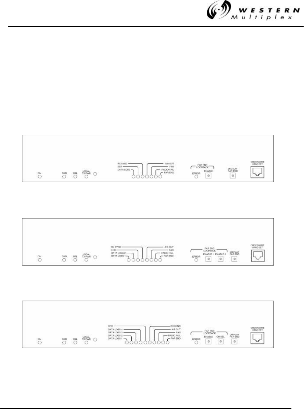
2.3 Front Panel Description
2.3.1 General
The LYNX.sc radio front panels, as shown in Figure 2-1 through 2-3, have LED indicators, test
points, controls and connections that are used for installation, maintenance, operation and
troubleshooting. Prior to installation, it is best to be familiar with the front panel of your particular
model. Sections 2.3.2 through 2.3.5 briefly describe the front panel access and lights from left to
right.
Figure 2-1: Front Panel, 2.4 GHz & 5.8 GHz 1xE1
Figure 2-2: Front Panel, 2.4 GHz & 5.8 GHz 2xE1
Figure 2-3: Front Panel, 2.4 GHz & 5.8 GHz GHz 4xE1

INSTALLATION AND MAINTENANCE MANUAL
LYNX.sc E1 FAMILY
SPREAD SPECTRUM RADIOS
SEPTEMBER 1999
PAGE 2-12 SECTION 2: PRODUCT DESCRIPTION
2.3.2 Test Points / Power Indicator
ON This is an LED indication. When lit GREEN, the LYNX.sc is powered.
The LYNX.sc radio products do not have an on/off switch.
GND This is a test point referenced to chassis ground. This is used in conjunction with the
next two test points to measure voltages related to radio performance.
RSL This is a test point which relates to the Received Signal Level (RSL). A voltage can be
measured with a voltmeter (using the GND test point for reference) which corresponds
to the actual power level of the incoming received signal. While the DISPLAY FAR
END button is pressed, this RSL voltage corresponds to the RSL of the far-end radio.
These measurements are used during installation, maintenance and troubleshooting.
LOCAL TX
PWR This is a test point which corresponds to the output transmit power of the radio. A
voltage can be measured with a voltmeter (using the GND test point for reference)
which corresponds to the actual power level of the outgoing signal. This measurement
is used during installation, maintenance and troubleshooting
.This voltage only applies to the near-end and does not allow measurement of
the far-end output transmit power, even when the DISPLAY FAR END button
is pressed.
There is a receptacle on the front panel to the right of the LOCAL TX PWR test point
which is an installation adjustment allowing the output transmit power to be increased
or decreased within the radio's specified limits. Using a small screwdriver, this
adjustment is used to set the output power of the transmitter, in accordance to the
path planning.
The LYNX.sc systems requires professional installation. Transmitted output
power limits may apply when using this radio. Consult FCC, IC, ETSI Western
Multiplex or other regulatory authorities for limits which may apply. See
Section 3.13.1 for details on setting output power.

INSTALLATION AND MAINTENANCE MANUAL
LYNX.sc E1 FAMILY
SPREAD SPECTRUM RADIOS
SEPTEMBER 1999
SECTION 2: PRODUCT DESCRIPTION PAGE 2-13
2.3.3 Alarm and Status Indicators
DATA
LOSS When lit RED, this is an alarm condition indicating that the LYNX.sc radio is not
receiving E1 input data on the corresponding data input channel. This alarm function
can be disabled by rear panel DIP switch setting (see Section 2.4.4). Under data loss
condition, the local transmitter injects AIS (Alarm Indication Signal).
BER This is the Bit Error Rate (BER) alarm. When lit RED, this alarm condition indicates
that the received signal bit error rate is above the error threshold of 1 x 10⁻⁶. This alarm
condition typically indicates a path problem or a problem with the far-end radio and
usually is not a problem with the near- end radio.
RX SYNC When lit RED, this is an alarm condition indicating that the intended received signal is
not being received. This alarm may indicate problems related to the path,
connections, or the near-end or far-end radio hardware. When the RX SYNC alarm is
active, AIS (Alarm Indication Signal) is injected into the E1 line transmit output data
port.
AIS OUT When lit RED, this is a status condition indicating that the radio receiver is
transmitting AIS (Alarm Indication Signal) on the E1 line transmit output data port, due
to loss of received signal. This typically indicates a path or connection problem or a
near-end or far-end radio hardware problem. This alarm function can be disabled by
rear panel DIP switch setting (see Section 3.12.5).
FAN When lit RED, this is an alarm condition indicating a failure with one or both of the
internal cooling fans. The radio is designed to operate within specification when only
one fan is operating. The two fans are provided for redundancy only.
RADIO
FAIL When lit RED, this is an alarm condition indicating a major failure with the near-end
radio hardware. It can also indicate improper connections to the CEPT-1 input port.
FAR END When lit RED, this is an alarm condition indicating that there are alarm or status
conditions present on the far-end radio. Press and hold the "Display Far End" button
on the near-end radios to indicate the alarm conditions for the far-end radio terminal.
Monitoring the far-end alarms can be helpful for radio installation and routine
maintenance.

INSTALLATION AND MAINTENANCE MANUAL
LYNX.sc E1 FAMILY
SPREAD SPECTRUM RADIOS
SEPTEMBER 1999
PAGE 2-14 SECTION 2: PRODUCT DESCRIPTION
2.3.4 Controls
Loopback is a test method used which transmits either an internal or external
E1 test signal and loops this E1 signal back at the far-end radio (re-transmits
the signal back to the near end). The near end then receives the signal. This
is very useful for testing because the test signal can be monitored at the
near-end and the quality of the entire link can be measured using a Bit Error
Rate (BER) test, or internal test features, without anyone going to the far-end
radio location.
ERROR When lit RED, this indicates that a bit error occurred while in loopback mode. If you
are not using a BER test set, this LED may be observed to determine if there are any
bit errors during loopback, for example during an overnight test.
ENABLE This is a push-button switch that executes the loopback mode for the corresponding
channel. Loopback is initiated by pressing and holding this switch for approximately 3
seconds. Once in loopback mode, the LED which is embedded in the switch is
illuminated YELLOW to indicate that Loopback is ON. The LED on the near-end radio
flashes while the far-end is solid. Loopback is disabled by pushing and releasing the
ENABLE button at either the near-end or far-end radio.
Enabling loopback will interrupt traffic. This is an out-of-service test.
CH SEL This is a push-button switch provided only one the 4xE1 version that selects the
channel for loopback mode. The channel is determined by the number of times the
switch is pressed. Press (hold for 2 seconds and release) for channel 1, press again
for channel 2, press again for channel 3 and press again for channel 4. Loopback is
initiated using the ENABLE switch; the LED in the CH SEL button flashes in a group
sequence to identify which channel is selected for loopback.
DISPLAY
FAR END This push-button provides the capability to determine alarms and status of the far-end
radio. When pressed and held, the alarm and status LEDs and the RSL test point
correspond to the far-end radio’s status and RSL value. This can be used for
installation, maintenance and troubleshooting. When the LED on this switch is
flashing, no far-end information is available. This typically indicates that there is no
link between near-end and far-end radios.

INSTALLATION AND MAINTENANCE MANUAL
LYNX.sc E1 FAMILY
SPREAD SPECTRUM RADIOS
SEPTEMBER 1999
SECTION 2: PRODUCT DESCRIPTION PAGE 2-15
2.3.5 Connections
ORDERWIRE
This connection is used to access the orderwire function. This is a facility for "telephone" style
service from one radio to another. A standard electronic telephone [one with a handset and DTMF
(push-button tone) dialing] plugs into this connector. The user can dial the orderwire address of the
far-end radio (or any radio in the LYNX.sc network) to establish telephone communication between
sites. This communication does not interrupt or interfere with the other radio communications. The
radio link must be operational to use this facility. The orderwire feature can be very useful for
installation, maintenance and troubleshooting.
-Touch-tone Telephone* (for communication with far-end)
*Telephone connection specifications:
REN (Ringer Equivalency Number) 1.0 B
DTMF tones within ±1.5% of nominal freq.
Ringing Voltage 48 VDC, typical
(Ringing voltage is adequate for modern solid state ringers,
NOT for the older mechanical type ringers)
INSTALLATION AND MAINTENANCE MANUAL
LYNX.sc E1 FAMILY
SPREAD SPECTRUM RADIOS
SEPTEMBER 1999
PAGE 2-16 SECTION 2: PRODUCT DESCRIPTION
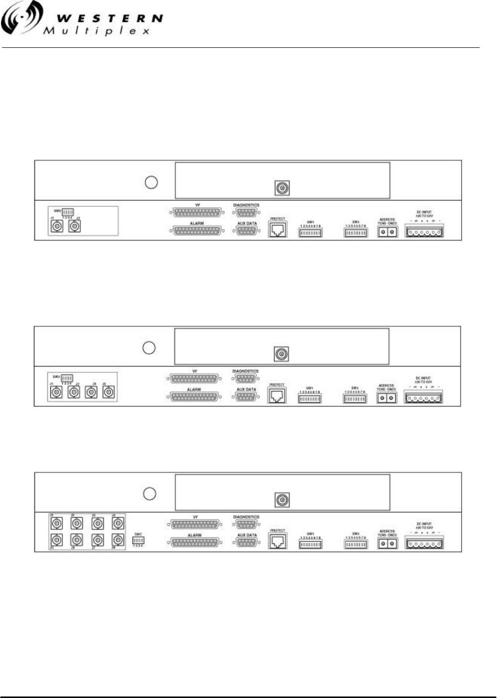
2.4 Rear Panel Description
The LYNX.sc radio rear panel, as shown in Figures 2-4 through 2-6, has connections and DIP
switches that are used for installation, maintenance, operation and trouble-shooting. Prior to
installation, you should familiarize yourself with the rear panel.
Figure 2-4: Rear Panel, 1xE1
Figure 2-5: Rear Panel, 2xE1
Figure 2-6: Rear Panel, 4xE1

INSTALLATION AND MAINTENANCE MANUAL
LYNX.sc E1 FAMILY
SPREAD SPECTRUM RADIOS
SEPTEMBER 1999
SECTION 2: PRODUCT DESCRIPTION PAGE 2-17
2.4.1 RF Connection
The RF port of the LYNX.sc radio is an N-type female connector that is an integral part of the filter
assembly. The filter assembly occupies nearly the entire top half of the rear panel. The N-Type
connector is used to connect the antenna, typically using coaxial transmission line. In some cases,
waveguide may be used as the primary transmission line, in which case a waveguide-to-N adapter
is required.
For the LYNX.sc, 1/2" or 5/8” coaxial cable (LDF4-50 or LDF4.5-
50) is recommended. Coaxial cable that is 7/8” or larger can
exhibit moding at 5.8 GHz and is not recommended for 5.8 GHz
radios. For waveguide transmission line at 5.8 GHz, EW-52
waveguide is recommended. EW-63 will also work, but may
exhibit more loss.
INSTALLATION AND MAINTENANCE MANUAL
LYNX.sc E1 FAMILY
SPREAD SPECTRUM RADIOS
SEPTEMBER 1999
PAGE 2-18 SECTION 2: PRODUCT DESCRIPTION
2.4.2 DATA Connections
The connection for the CEPT-1 (E1) interface is shown in Figure 2-7 as J1 through J4 (additionally
J5 through J8 on the 4xE1 model). These connections carry the E1 signals in and out of the radio.
Multiple capacity (2xE1 and 4xE1) provide extra sets of input and output ports to connect each E1
signal.
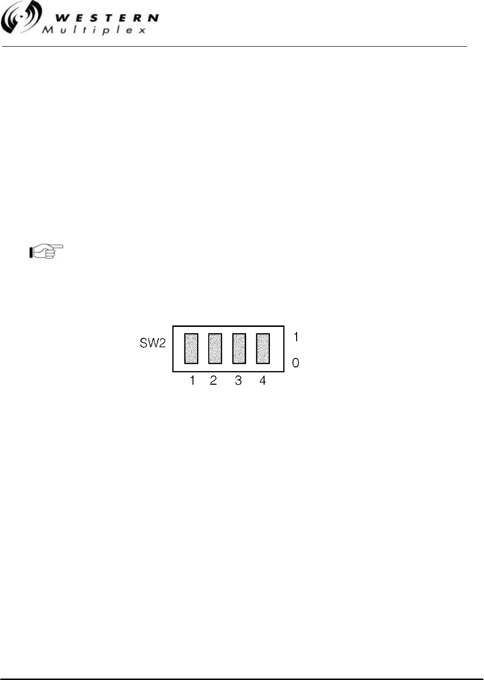
The BNC data ports accept bipolar signals with the shield normally left open (floating) in order to
eliminate ground loop problems. If desired, the BNC shield on the data ports may be grounded using
switch settings on SW2.
For balanced E1 input, use a 120 ohm balun and BNC cables to
provide a RJ45 4-wire connection. SW2 has no effect when using
the typical balun.
Figure 2-7: CEPT-1 Interface Grounding Switch

INSTALLATION AND MAINTENANCE MANUAL
LYNX.sc E1 FAMILY
SPREAD SPECTRUM RADIOS
SEPTEMBER 1999
SECTION 2: PRODUCT DESCRIPTION PAGE 2-19
2.4.3 Auxiliary Data Connections
There are 5 auxiliary data connections for LYNX.sc as shown in Figure 2-4 through Figure 2-6.
VF This connector is used to link two LYNX.sc radios at a repeater site for Orderwire
operation. This would allow orderwire "telephone" calls to and from any point in the
LYNX.sc network.
The LYNX.sc orderwire circuit can also be connected to other existing
orderwire networks. See Section 3.14.1 for details.
ALARM This connector is used for monitoring alarms electrically. The alarm connections are
essentially the same as described for the front panel, however instead of LED
operation, alarm status is provided electrically by means of TTL and Form C relay
connections. The TTL and Form C relays can be connected to other transmission
equipment for monitoring alarm status locally or remotely.
DIAG-
NOSTICS This is a serial interface port (RS-232 or RS-422, ≤9600 baud) to the LYNX.sc radio.
This port provides maintenance information about the LYNX.sc radio(s) to a connected
computer or terminal. This port is typically used for maintenance and troubleshooting
or connection to network management systems.
AUX
DATA This is a serial interface port (RS-232 or RS-422, ≤9600 baud) which allows the user
to connect auxiliary serial data from one point in the radio network to another. This
facility can also be used for bridging the DIAGNOSTICS port for remote alarm and
status monitoring (TBOS network management) or for connecting other equipment's
serial alarm information. It can alternatively be used for separate data connection for
LANs or other serial devices.
PROTECT This is a port used to connect the LYNX.sc radio to an additional unit for Monitored
Hot Standby (MHS) or Space Diversity (SD) configuration. The MHS and SD units can
be configured to provide protection to the LYNX.sc radio by means of a "back-up"
radio which would switch-in should there be problems with the primary radio or the
radio path.
The protect feature is not available at the time of the printing
of this manual

INSTALLATION AND MAINTENANCE MANUAL
LYNX.sc E1 FAMILY
SPREAD SPECTRUM RADIOS
SEPTEMBER 1999
PAGE 2-20 SECTION 2: PRODUCT DESCRIPTION
2.4.4 Switches
There are two sets of 8-segment DIP switches (SW1 & SW3) and two rotary switches (Address
TENS and ONES), as shown in Figures 2-4 through 2-6 on the rear panel of the LYNX.sc radio.
These switches provide user configuration of several radio parameters. A brief explanation for each
function follows.
Refer to the switch setting detail in Appendix B for your
particular model.
SW1
Input
Alarm
Disable
These switch segments allow the user to “turn off” the DATA LOSS alarm for any input
channel. This can be helpful if the data channel is not in use or while performing
maintenance to temporarily turn off the alarm indication. Even when this alarm is
disabled, the LYNX.sc radio will inject AIS into the transmitted data stream when
there is a data loss condition. (see Section 3.12.4)
Loopback
Mode This switch segment allows the user to select either the internal or an external test
signal while in loopback mode. (see Section 3.12.2)
Error
Unlatch This switch segment selects an optional mode for the ERROR LED to flash for each
error occurrence (instead of latching on). This can be useful for short duration
loopback testing when the operator is located at the terminal site and watching for
errors. (see Section 3.13.3)
AIS
Disable This switch segment allows the user to select whether or not an AIS signal will be
automatically injected into the received E1 data stream at BER ≥ 1 x 10⁻³. This can be
useful for measuring threshold or when a E1 channel is not in use. The AIS will be
injected into the received E1 data stream if the radio loses sync (RX SYNC alarm
active), even if the AIS disable function has been selected. (see Section 3.12.5)
Diag-
nostic
Protocol
This switch segment is default set to Telemetry Bit Oriented Serial (TBOS) mode on
the diagnostics port. This is a non-proprietary network management protocol which is
common to some radio networks. The other selection is for factory use only. (see
Section 3.14.3)
Enable
Aux
Data
This switch segment allows the AUX DATA port to be optionally used as a clear
service channel for RS-232 or RS-444 (≤ 9600 baud) user data. The radio normally
“bridges” the AUX DATA port to the DIAGNOSTICS PORT for TBOS radio network
management. (see Section 3.14.4)

INSTALLATION AND MAINTENANCE MANUAL
LYNX.sc E1 FAMILY
SPREAD SPECTRUM RADIOS
SEPTEMBER 1999
SECTION 2: PRODUCT DESCRIPTION PAGE 2-21
SW2
Interface
Connec-
tion
These switch segments allow the user to have the shield of each CEPT-1 input
connection either grounded or floating. The shield is normally “floating” to eliminate
ground loop problems. (see Section 3.11)
SW3
Spread-
ing Code This set of switch segments allow the user to select the spreading code for the spread
spectrum signal. Both ends of a radio system must be set to the same code. Users
may wish to change codes for radios that are nearby other similar radios to aid in
interference rejection. (see Section 3.12.3)
Channel
Selection This set of switch segments programs the radio to match the specific RF channel
corresponding to the RF filter set which has been installed. (see Section 3.12.1)
Address There are two rotary switches which determine the radio's address (01 to 99). This
address is used for Orderwire signaling and for the DIAGNOSTICS port TBOS
address. (see Section 3.14.1)
Refer to Appendix B for Switch Settings

INSTALLATION AND MAINTENANCE MANUAL
LYNX.sc E1 FAMILY
SPREAD SPECTRUM RADIOS
SEPTEMBER 1999
PAGE 2-22 SECTION 2: PRODUCT DESCRIPTION
2.5 Installation Accessories
The LYNX.sc radio is shipped with several accessories commonly required for the radio as
described below:
AC Power
Supply If ordered as an option, this power supply provides AC to DC conversion for use with
AC powered locations.
AC Power
Cord This power cord connects the AC Power Supply, if ordered, to a standard 115V U.S.
AC outlet.
Rack Mount
Brackets Two brackets (along with required mounting screws) are provided which allow 19-
inch rack mounting of the LYNX.sc radio.
Terminal
Connector This is a 6-pin mating connector used for DC power supply.
D
Connector
9-pin
Two of these mating connectors are provided. One is used for the DIAGNOSTICS
port interface and another for the AUX DATA port.
D
Connector
25-pin
There are 2 mating connectors provided, one for the ALARM interface and the other
for the VF interface.
RF Power
Adjustment
Cover
A small plastic cap is provided which is placed over the RF output power adjustment
receptacle once output power has been set by professional installation personnel.
Other accessories are available, such as orderwire handsets, connector adapters and special
cables. These can be ordered separately upon request.

INSTALLATION AND MAINTENANCE MANUAL
LYNX.sc E1 FAMILY
SPREAD SPECTRUM RADIOS
SEPTEMBER 1999
SECTION 2: PRODUCT DESCRIPTION PAGE 2-23
Your Notes on the LYNX.sc Radio

INSTALLATION AND MAINTENANCE MANUAL
LYNX.sc E1 FAMILY
SPREAD SPECTRUM RADIOS
SEPTEMBER 1999
SECTION 3: INSTALLATION & ADJUSTMENTS PAGE 3-1
3. Installation & Adjustments
3.1 Shipping Container
The equipment is shipped in boxes unless ordered as an integrated system and configured at the
factory, in which case the equipment may be racked and shipped in a crate. The equipment is
packaged so as to prevent damage in transit.
The boxes should be left intact and sheltered until arrival at the installation site.
If the shipping container shows signs of damage, the
transportation company should be notified immediately. Extra
care and inspection of the contents is advised immediately upon
receipt.
It is recommended that all the packaging materials be
retained. In the unlikely event that the equipment must be
returned to the factory, use the original packing materials for
return shipment. The original packaging materials are also
recommended for transporting the equipment from location
to location.
Inside the primary shipping containers, internal boxes may contain other items. These boxes should
also be saved for future use.
Also, save the LYNX.sc radio test data sheet that is provided.
The test data sheet can be placed where the LYNX.sc terminal
will be installed for future quick reference. This sheet could also
be placed in the front pocket of this manual, and the manual
kept at the radio location for future reference. All LYNX.sc units
are individually tested and the actual measured performance
recorded on the Factory Test Data Sheet. You will find this
information to be of use during installation, troubleshooting and
maintenance.
A set of quick installation instructions is also provided which can be useful for easy reference during
installation.

INSTALLATION AND MAINTENANCE MANUAL
LYNX.sc E1 FAMILY
SPREAD SPECTRUM RADIOS
SEPTEMBER 1999
PAGE 3-2 SECTION 3: INSTALLATION & ADJUSTMENTS
3.2 Packing Items Identification
The primary shipping container houses the radio and an additional box. The box contains several
related items inside including:
vThis manual
vInstallation accessory kit (see Section 2.5)

INSTALLATION AND MAINTENANCE MANUAL
LYNX.sc E1 FAMILY
SPREAD SPECTRUM RADIOS
SEPTEMBER 1999
SECTION 3: INSTALLATION & ADJUSTMENTS PAGE 3-3
3.3 Before Installation Task List
There are several tasks that should be accomplished prior to installing the LYNX.sc radio system.
This section briefly describes the following:
- Site selection
- Line-of-Sight and Path Clearance determination
- Anticipated RSL calculation
- Fade margin calculation
- Availability calculation
- Frequency plan determination
- Power supply planning
- Antenna (and accessories) purchase
Only directional antennas should be used with LYNX.sc spread
spectrum radios. These can be grid or solid parabolic antennas
(minimum 2 foot - .6 meter). Flat panel antennas are also
acceptable if the beam width is kept to a minimum.
3.3.1 Site Selection Requirements
The radio site must have:
- access to the appropriate power
- close proximity to the telephone or computer system you wish to interconnect
- line-of-sight to the other radio location with adequate clearance
- location for mounting the antenna

INSTALLATION AND MAINTENANCE MANUAL
LYNX.sc E1 FAMILY
SPREAD SPECTRUM RADIOS
SEPTEMBER 1999
PAGE 3-4 SECTION 3: INSTALLATION & ADJUSTMENTS
3.3.2 Line-of-Sight and Path Clearance Guidelines
The LYNX.sc radios will not operate properly unless they have line-of-sight between their
corresponding antennas. The LYNX.sc radio transmission will not pass through trees or other
obstacles. Factors to consider include:
- Earth curvature
- Future growth of trees
- Height of buildings
In addition to the line-of-sight requirement, a well-engineered path will also have additional path
clearance to allow for signal loss due to partial obstructions, atmospheric ducting and ground
reflections. To maximize radio reception, 0.6 times the first Fresnel zone should be calculated and
this distance added to the path clearance (in addition to trees or buildings).

INSTALLATION AND MAINTENANCE MANUAL
LYNX.sc E1 FAMILY
SPREAD SPECTRUM RADIOS
SEPTEMBER 1999
SECTION 3: INSTALLATION & ADJUSTMENTS PAGE 3-5
3.3.3 RSL Calculation and Link Budget
The received signal level (RSL) can be estimated using the following formula:
RSL (dBm) = Pout - FL1+ G1 + G2 - FL2 - Lp
where: Pout is the transmitter output power (in dBm)
FL1 is the feeder loss of the transmit side (in dB)
G1 is the gain of the transmit antenna (in dB)
G2 is the gain of the receive antenna (in dB)
FL2 is the feeder loss of the receive side (in dB)
Lp is the Path loss, defined by:
Lp (dB) = 96.6 + 20 log10F + 20 log10D
where: F = Frequency in GHz (2.4 or 5.8)
D = Distance of path in miles
This link budget is very important for determining any potential problems during installation. If you
have calculated the expected RSL, you can see if it has been achieved during installation, and
troubleshoot if necessary.
In the USA, 5.8 GHz models of the LYNX.sc may be installed
with any size directional antennas and operated at full power.
The 2.4 GHz model may require power reduction where: Pout -
FL1+ G1 is replaced by 30 - [(G1 - 6)/ 3] + FL1
In some countries effective isotropic radiated power (EIRP)
limits apply, such as +6 dBW (+36 dBm) in Canada. Output
power may need to be reduced, and the above path planning
equation changed such that: EIRP (dBm) = Pout + G1 - FL1

INSTALLATION AND MAINTENANCE MANUAL
LYNX.sc E1 FAMILY
SPREAD SPECTRUM RADIOS
SEPTEMBER 1999
PAGE 3-6 SECTION 3: INSTALLATION & ADJUSTMENTS
3.3.4 Fade Margin Calculation
The fade margin is the difference between the actual received signal and the radio’s threshold. Using
the formula provided in Section 3.3.3, the anticipated RSL can be calculated. Compare this RSL to
the specified threshold of the LYNX.sc radio, which is shown in Section 2.2, and calculate the fade
margin as the difference between the two signal levels.
Dispersive fade margin is another factor that many microwave path engineers may use to plan their
link budget. For the LYNX.sc radio, the dispersive fade margin is in excess of 55 dB and therefore
is not a determining factor in path planning. This excellent dispersive fade margin performance is
important because the spread spectrum RF signal has considerably wide bandwidth.

INSTALLATION AND MAINTENANCE MANUAL
LYNX.sc E1 FAMILY
SPREAD SPECTRUM RADIOS
SEPTEMBER 1999
SECTION 3: INSTALLATION & ADJUSTMENTS PAGE 3-7
3.3.5 Availability Calculation
Availability of the microwave path is a measure of the percent of the time that the link will operate
without producing an excessive BER due to multipath fading. In the absence of direct interference,
availability is affected by the following:
- Path length
- Fade margin
- Frequency (2.4 GHz or 5.8 GHz in the case of the LYNX.sc radios)
- Terrain (smooth, average, mountainous)
- Climate (dry, temperate, hot/humid)
Depending on the type of traffic carried over the link, the system designer may wish to design for a
specific availability. For example, if the data or voice traffic that is carried by the radio is critical then
it may be designed for a very high availability (e.g. 99.999% or 5.3 minutes of outage per year). To
improve availability, for example, the fade margin can be increased by making the path shorter, or
by using higher gain antennas in conjunction with lower loss feeders (by using high quality
transmission line or shortening feed length).

INSTALLATION AND MAINTENANCE MANUAL
LYNX.sc E1 FAMILY
SPREAD SPECTRUM RADIOS
SEPTEMBER 1999
PAGE 3-8 SECTION 3: INSTALLATION & ADJUSTMENTS
3.3.6 Frequency Plan Determination
When configuring radios in a hub or repeater configuration, careful engineering of the LYNX.sc radio
frequency plans and antenna locations should be performed in order to minimize potential
interference between the nearby radios. As a rule of thumb, do not place identical frequency plan
radios (e.g. two “A” channel radios) at the same site. In most cases, it is desirable to use a different
frequency plan (e.g. A versus B). However, with careful engineering, placing more than one radio of
the same frequency channel plan at the same site can be accomplished. In fact, the LYNX.sc
frequency plan is designed to allow complex hub configurations that may require re-using the same
frequency plan. When designing these types of configurations, antenna size and antenna location
are critical. If identical channel plans must be used at the same site, the same radio channel (e.g.
A1 and A1) should be used at a site to minimize interference. Using alternate channels (e.g. A1 and
A2) is less likely to be successful (and therefore not recommended) due to the high level of
transmitter to receiver isolation required from the antenna system.
Sometimes it is required to locate the LYNX.sc radio nearby a transmitter that is the same as, or
close to the LYNX.sc receive or transmit frequencies. In this case, the LYNX.sc terminal that
should be placed closest to this interfering transmitter should be the specific terminal with the
receive frequency which is furthest from this unwanted transmitted frequency. This approach
minimizes the potential of interference. While interference conditions are rare when using the
LYNX.sc radios, cases of interference may be overcome by exchanging the radios from end to end
or simply reinstalling the filter unit, as described in Section 4.2 (thus swapping the frequencies of
both ends of the radio link). In some cases, changing frequency plans (e.g. from A to B) can also
help mitigate any interference.
Section 4.8 of this manual describes interference
countermeasures in further detail.

INSTALLATION AND MAINTENANCE MANUAL
LYNX.sc E1 FAMILY
SPREAD SPECTRUM RADIOS
SEPTEMBER 1999
SECTION 3: INSTALLATION & ADJUSTMENTS PAGE 3-9
3.3.7 Power Supply Planning
The LYNX.sc radio must have access to a supply of appropriate power, either DC or AC (if the AC
adapter option has been ordered). The LYNX.sc can be powered from a DC battery system, or from
a solar or generator power plant, usually with battery reserves. Typically either a positive or negative
ground 24 or 48 volt supply is used. For DC, be sure the cable is of sufficient gauge to carry the
necessary current and it is less than three (3) meters (9.75 feet) in length.
Before installing the radio, plan for the continuous power consumption needs in accordance with the
specifications given in Section 2.2 of this manual. It is also wise to plan for backup power for critical
communication circuits (including the LYNX.sc radio). Backup power allows the radios and
associated equipment to continue operation when primary power is interrupted.

INSTALLATION AND MAINTENANCE MANUAL
LYNX.sc E1 FAMILY
SPREAD SPECTRUM RADIOS
SEPTEMBER 1999
PAGE 3-10 SECTION 3: INSTALLATION & ADJUSTMENTS
3.3.8 Antenna Planning
Using the path planning tools, proper antenna size can be determined which will yield the desired
path performance. In general, the larger the antenna that is used with the LYNX.sc radio, the better
the link will perform. Larger antennas have narrower beamwidth and higher gain, which will yield
better link performance (higher fade margin, better availability) and improve immunity to interference
(due to the smaller beamwidths). However, larger antennas are more costly to purchase and install
than smaller antennas, in some cases requiring special equipment for installation. All of these
factors should be taken into consideration when selecting antennas.
In areas where transmitted output power restrictions apply, the
use of larger antennas will maintain the benefit of narrow
beamwidths and receive gain. However, output power may need to
be reduced to meet regulations. (See Section 3.13.1)
Prior to installation, the specific antenna location and mounting should be determined. This
advanced planning also yields the transmission line requirements.
Only directional antennas should be used with LYNX.sc spread
spectrum radios. These can be grid or solid parabolic antennas
(minimum 2 foot - .6 meter). Flat panel antennas are also
acceptable if the beam width is kept to a minimum.

INSTALLATION AND MAINTENANCE MANUAL
LYNX.sc E1 FAMILY
SPREAD SPECTRUM RADIOS
SEPTEMBER 1999
SECTION 3: INSTALLATION & ADJUSTMENTS PAGE 3-11
3.4 Tools Required
The following tools may be required for the installation of the LYNX.sc radios:
-Phillips (cross tip) screwdrivers (for 19-inch rack mounting and attachment of brackets)
-Small blade standard screwdriver (for power supply connector and RF output power
adjust)
-Soldering iron (if using any D-type connectors)
-Wire strippers (for removing insulation from power supply and other wiring)
-Digital Voltmeter (to measure RSL, Tx output power, Alarms)
The following tools are recommended for the installation of the LYNX.sc radios:
-RF power meter (to measure transmitter output power)
-Cellular phone or two-way radio (for talking with far-end crew and tower crew)
-Bit Error Rate test set (to test link after installation)
-Touch-tone Telephone* (to test orderwire circuits and for communication with far-end)
Additional tools will likely be needed for antenna and transmission line installation and antenna
alignment. Consult Sections 3.8 through 3.10 of this manual for more details.
*Telephone connection specifications:
REN (Ringer Equivalency Number) 1.0 B
DTMF tones within ±1.5% of nominal freq.
Ringing Voltage 48 VDC, typical
(Ringing voltage is adequate for modern solid state ringers,
NOT for the older mechanical type ringers)
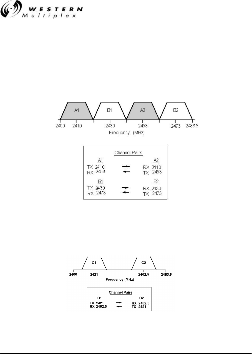
INSTALLATION AND MAINTENANCE MANUAL
LYNX.sc E1 FAMILY
SPREAD SPECTRUM RADIOS
SEPTEMBER 1999
PAGE 3-12 SECTION 3: INSTALLATION & ADJUSTMENTS
3.5 Frequency Channel Plans
The LYNX.sc system offers several non-overlapping channel plans for the different models of radio.
This channel plan arrangement allows users to implement LYNX.sc systems in the proximity of
other LYNX.sc radios (planned or unplanned), hub and repeater applications, and can be used to
mitigate interference. The channel plans are illustrated below in Figures 3-1 through 3-6. Section 4.2
and 4.3 describe how to change frequency channel assignments of a LYNX.sc radio.
Figure 3-1: Channel Plan, 2.4 GHz 1xE1
Figure 3-2: Custom Channel Plan, 2.4 GHz E1
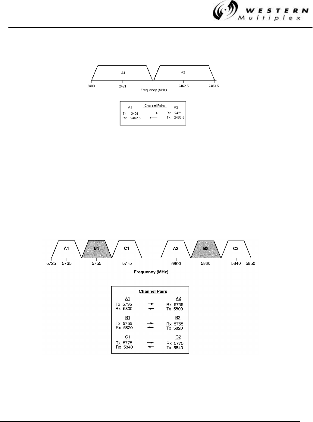
INSTALLATION AND MAINTENANCE MANUAL
LYNX.sc E1 FAMILY
SPREAD SPECTRUM RADIOS
SEPTEMBER 1999
SECTION 3: INSTALLATION & ADJUSTMENTS PAGE 3-13
Figure 3-3: Channel Plan, 2.4 GHz 2xE1
Figure 3-4: Channel Plan, 5.8 GHz 1xE1
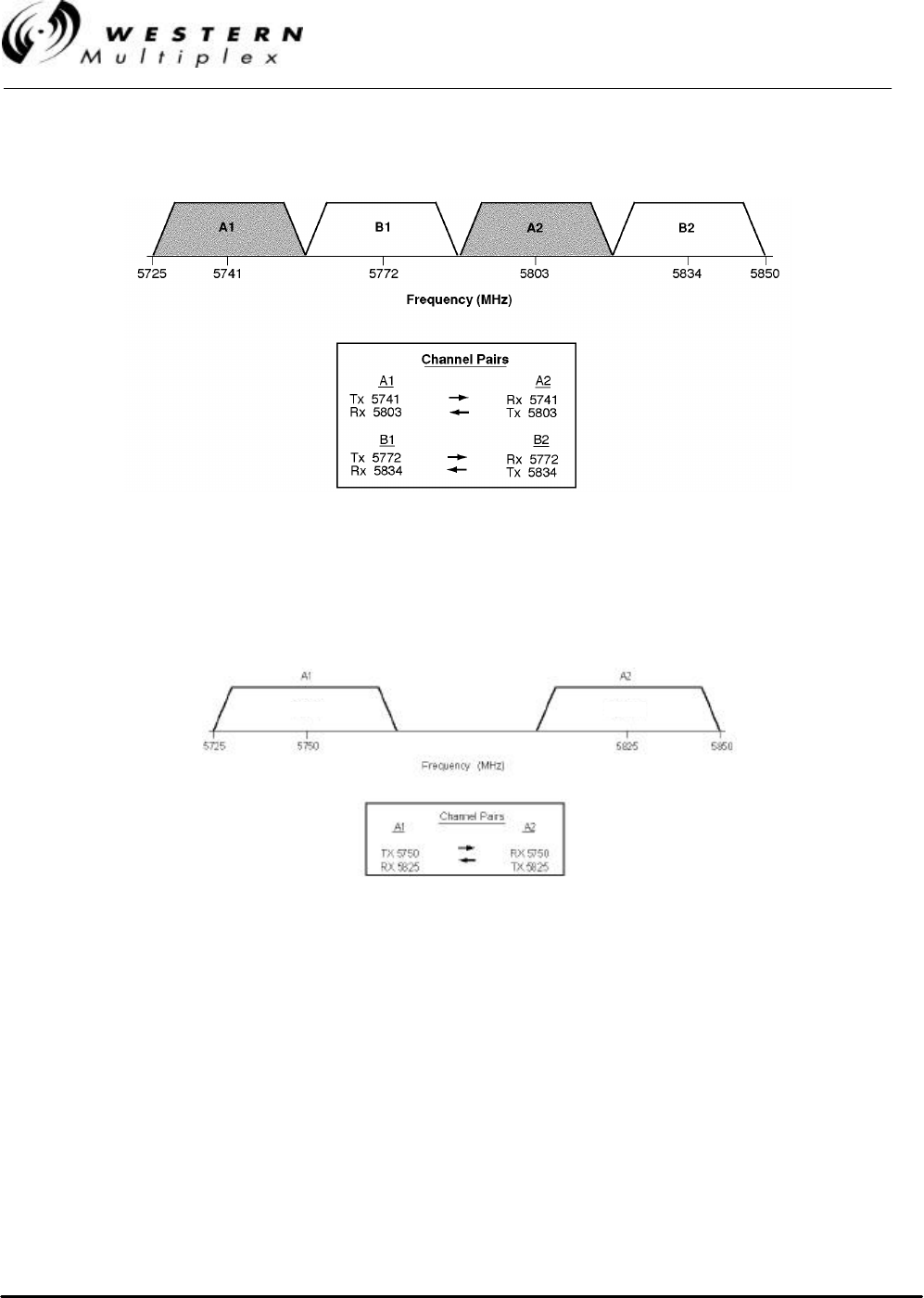
INSTALLATION AND MAINTENANCE MANUAL
LYNX.sc E1 FAMILY
SPREAD SPECTRUM RADIOS
SEPTEMBER 1999
PAGE 3-14 SECTION 3: INSTALLATION & ADJUSTMENTS
Figure 3-5: Channel Plan, 5.8 GHz 2xE1
Figure 3-6: Channel Plan, 5.8 GHz 4xE1

INSTALLATION AND MAINTENANCE MANUAL
LYNX.sc E1 FAMILY
SPREAD SPECTRUM RADIOS
SEPTEMBER 1999
SECTION 3: INSTALLATION & ADJUSTMENTS PAGE 3-15
3.6 Mounting the LYNX.sc
The LYNX.sc radio can be mounted at any height in a standard 19-inch rack. Blank rack-mounting
spaces above and below the LYNX.sc are recommended, especially if the surrounding equipment
dissipates a considerable amount of heat (over 50W).
The LYNX.sc radio may be set up for mounting with the front edge projecting from the front face of a
standard 19-inch rack using the rack mounting brackets enclosed with the screws in the Accessory
Kit (4 per bracket). The rack mounting brackets may be reversed, in order to install for flush or
cabinet mounting if preferred. Depending on rack configuration, it may be necessary to remove the
four adhesive backed rubber feet on the bottom of the unit.
The LYNX.sc radio has internal fans which intake and exhaust
on the left and right sides of the chassis. When rack mounting,
it is important to leave a small gap between the outer edges of
the radio and the inside edge of the rack.
The LYNX.sc radio may alternatively be placed on a table or shelf
attached to a wall. Because of the low weight of the LYNX.sc, any
mounting option other than rack mounting will be less secure.

INSTALLATION AND MAINTENANCE MANUAL
LYNX.sc E1 FAMILY
SPREAD SPECTRUM RADIOS
SEPTEMBER 1999
PAGE 3-16 SECTION 3: INSTALLATION & ADJUSTMENTS
3.7 Power Connection and Wiring
There is no ON/OFF switch on the LYNX.sc. As soon as
power is applied, the equipment will be operational. This
means that there can be up to 1W of RF power present at
the antenna port. The antenna port should be terminated
before power is applied.
Power is connected using the DC power plug contained in the Accessory Kit. Use Table 3-A or 3-B
along with the associated diagram of Figure 3-7 or 3-8 to connect the DC power cables. For
example, for a negative DC power input, use Table 3-A and Figure 3-7.
NEGATIVE DC POWER INPUT
(–20 TO –63 VDC)
PIN FUNCTION
1Power (–DC)
2Ground (see figure 3-7)
3Return (+DC)
4Return (+DC)
5Ground (see figure 3-7)
6Power (–DC)
Table 3-A: DC Power Connection for Negative Supply
POSITIVE DC POWER INPUT
(+20 TO +63 VDC)
PIN FUNCTION
1Return (–DC)
2Ground (see figure 3-8)
3Power (+DC)
4Power (+DC)
5Ground (see figure 3-8)
6Return (–DC)
Table 3-B: DC Power Connection for Negative Supply
Pins 1 and 6 are connected together on the motherboard. Either
pin may be used to apply (-DC) DC power input. Similarly, pins 3
and 4 are connected together on the motherboard and may be
used to apply (+DC) DC power input.
For DC power return connection, connect to the opposite voltage
(either the -DC or the +DC Pin) and connect the return to ground
at the DC power plug on pins 2 and/or 5.

INSTALLATION AND MAINTENANCE MANUAL
LYNX.sc E1 FAMILY
SPREAD SPECTRUM RADIOS
SEPTEMBER 1999
SECTION 3: INSTALLATION & ADJUSTMENTS PAGE 3-17
3.7.1 DC Power Wiring
Connect the power cable with adequate current rating (minimum of 20 AWG) to the terminals shown
on the removed (not plugged into the radio) DC power plug using the screw connections. The
recommended minimum current rating of external fuses and cables is 3 Amps. The LYNX.sc radios
consume less than 1 Amp at ±48V and less than 2 Amps at ±24V. Be sure the DC power cable is
less than 3 meters (9.75 feet) in length.
Each LYNX.sc terminal should be externally fused separately
with a 5 Amp maximum fuse. The DC power cable must be less
than three (3) meters in length.
If using negative power, connect the negative voltage to pins 1 or 6. Connect the ground return
connection to pins 3 or 4. See Figure 3-7.
If using positive power, connect the positive voltage to pins 3 or 4. Connect the ground return
connection to pins 1 or 6. See Figure 3-8.
The ground connection is available at pins 2 and 5. Either pin may be used to ground the return
side of the power supply. Do not ground both sides of the power supply.
Proper grounding, either through the chassis and/or the power
supply, can be very important for protection from lightning. A
grounding screw hole is provided on the rear panel.
The ground connection may be left floating if the power supply is
referenced to ground externally and to avoid ground loops in
some configurations. However, this may not provide adequate
grounding for lightning protection.
Use a DVM (digital voltmeter) to verify voltage and polarity on the DC power plug.
Do not connect the DC power plug to the rear of the LYNX.sc
terminal until a load is connected to the antenna port (either an
RF pad, or an RF cable and antenna).
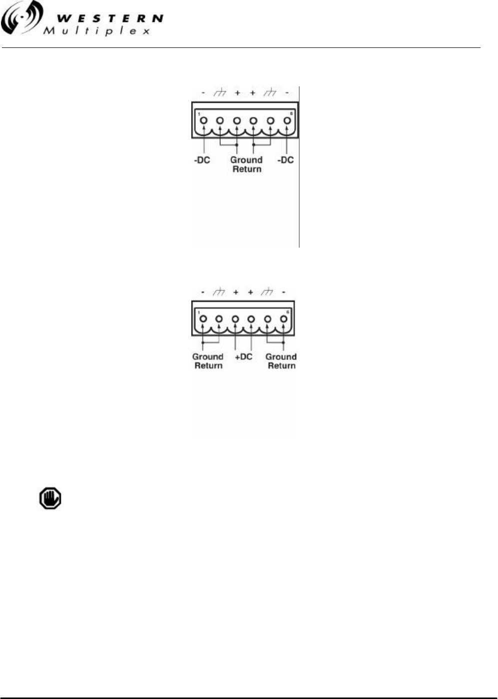
INSTALLATION AND MAINTENANCE MANUAL
LYNX.sc E1 FAMILY
SPREAD SPECTRUM RADIOS
SEPTEMBER 1999
PAGE 3-18 SECTION 3: INSTALLATION & ADJUSTMENTS
Figure 3-7: Negative Voltage DC Connection
Figure 3-8: Positive Voltage DC Connection
Make sure that when connecting the mating plug that it is properly
oriented (terminal screws pointing up) and securely fastened.
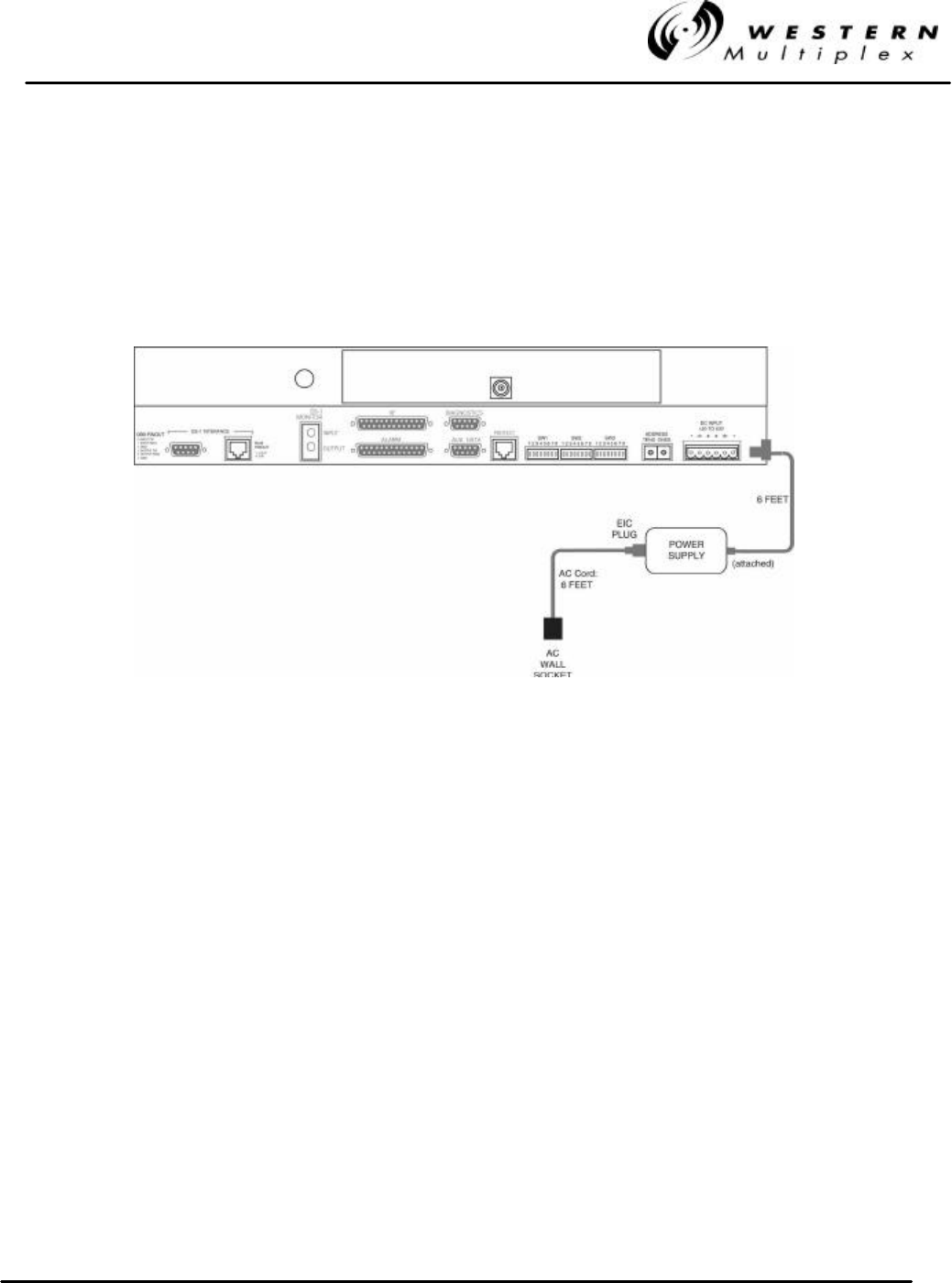
INSTALLATION AND MAINTENANCE MANUAL
LYNX.sc E1 FAMILY
SPREAD SPECTRUM RADIOS
SEPTEMBER 1999
SECTION 3: INSTALLATION & ADJUSTMENTS PAGE 3-19
3.7.2 AC Power Connection
The optional AC power supply operates from any AC voltage 100V - 250V and 50 Hz or 60 Hz. The
AC supply is equipped with a mating connector that plugs directly into the LYNX.sc radio and an
AC cord with a 3-pin AC plug. The AC cord color code is shown in Figure 3-9 in case users wish to
replace the AC plug supplied with a different type of plug.
Figure 3-9: AC Connection

INSTALLATION AND MAINTENANCE MANUAL
LYNX.sc E1 FAMILY
SPREAD SPECTRUM RADIOS
SEPTEMBER 1999
PAGE 3-20 SECTION 3: INSTALLATION & ADJUSTMENTS
3.8 Antenna Connection
The LYNX.sc radio is equipped with an N-type female connector at the antenna port located on the
rear panel. A short length (~6 feet) jumper cable such as RG-214 coax (or “pigtail”) fitted with two N-
type male connectors can be used to connect the antenna port to the antenna transmission line
(see Section 3.9). The recommended cable type for a jumper is RG-214.
A low loss 50-ohm cable (for example LDF4-50 1/2 inch coax) or EW-52 waveguide (for 5.8 GHz
radios) is recommended for the antenna transmission line between the top of the rack and the
antenna. The return loss presented by the transmission line at the top of the rack should be as high
as possible (20 dB, minimum recommended). The length of the antenna transmission line should be
kept as short as possible (to minimize losses).
For 5.8 GHz radios, to minimize feeder losses, the use of 5.8 GHz elliptical waveguide is
recommended (typical loss is 1.25 dB/100 ft) for feeder lengths in excess of 200 feet. Depending on
path length and feeder length, 1/2 inch coax cable can be used with 5.8 GHz radios.
For the LYNX.sc radio, 1/2” or 5/8” coaxial cable (LDF4-50 or
LDF4.5-50) is recommended. Coaxial cable 7/8” or larger can
exhibit moding at 5.8 GHz and is not recommended for 5.8 GHz
radios. For waveguide transmission line at 5.8 GHz, EW-52
waveguide is recommended. EW-63 will also work, but may
exhibit more loss.
Do not use right angle N-type connectors with the 5.8 GHz
LYNX.sc radios: they may present high loss at 5.8 GHz. Do not
use a low quality N-type jumper cable with the LYNX.sc. Some
cable types, such as RG-8, may have high loss at 5.8 GHz.

INSTALLATION AND MAINTENANCE MANUAL
LYNX.sc E1 FAMILY
SPREAD SPECTRUM RADIOS
SEPTEMBER 1999
SECTION 3: INSTALLATION & ADJUSTMENTS PAGE 3-21
3.9 Transmission Line Connection
The transmission line feeder (such as LDF4-50 1/2 inch coax cable or EW-52 elliptical waveguide)
should be prepared first by cutting to the approximate length (allowing some excess) and installing
the appropriate connector on the antenna end.
The prepared transmission line is then pulled through the cable ducts, trays or conduit (as required)
to the antenna, while being careful not to kink or damage the transmission line in any way.
The transmission line should be supported in a tray on horizontal runs and by hangers on vertical
runs. Hangers should be spaced according to the manufacturer’s instructions (typically every 5 feet
under conditions of no ice and not greater than 85 mph winds).
The transmission line should be grounded using the manufacture’s recommended grounding kit.
Grounding kits attach to the outer copper conductor. Grounds must be installed at the antenna, at
the bottom of the tower (if applicable) and where the transmission line enters the building. Long
transmission line runs should be grounded every 100 feet. In areas of high incidence of lightning,
dissipaters should be attached to antennas. In addition, coaxial, in-line, spark-gap type, lightning
suppressors should be added at the bottom of the coax cable before entering the
building/enclosure.
Any in-line lightning protection device must be rated for the
operating frequency of the LYNX.sc (2.4 or 5.8 GHz).
After installation, the transmission line is terminated with an N-type male connector/adapter
attached at the equipment end. For waveguide, this typically requires a CPR-to-N adapter.
Prior to operation, the electrical integrity of the transmission line, including all connectors, can be
checked with a simple DC check between the center conductor and outer conductor. (This is
neither possible, nor required for waveguide).
The transmission line should ideally be connected directly to the antenna at one end and to the
LYNX.sc antenna port at the other end. However, short RG-214 type pigtail jumper cables may be
required to avoid sharp bends in the transmission line to limit stress on either connection.
7/8 inch coax cable or larger is not recommended for use at 5.8
GHz and higher frequencies.
Do not use right angle N-type connectors with the 5.8 GHz
LYNX.sc radios: they may present high loss at 5.8 GHz. Do not
use a low quality N-type jumper cable with the LYNX.sc. Some
cable types, such as RG-8, may have too high a loss at 5.8
GHz.

INSTALLATION AND MAINTENANCE MANUAL
LYNX.sc E1 FAMILY
SPREAD SPECTRUM RADIOS
SEPTEMBER 1999
PAGE 3-22 SECTION 3: INSTALLATION & ADJUSTMENTS
3.10 Antenna Installation & Alignment
The antenna installation consists of mounting the antenna on the tower, building roof, or other
location that provides line-of-sight path clearance to the far-end location. In general, antennas
smaller than 2 feet diameter are not recommended for urban areas due to their wider beamwidths,
which results in higher interference susceptibility. For 2.4 GHz LYNX.sc radios, a minimum of 4 foot
(1.2m) diameter antennas, or larger, are recommended.
Antennas should be ordered with a suitable mounting kit specific to the site requirements. For
example, specifying round or angle tower leg adapters, or a roof tripod as necessary.
If the antenna is to be mounted indoors, "looking" through a window, it is recommended that the
antenna be placed approximately 12 inches away from the glass and within 10 degrees of a right
angle to the glass. The glass should be lead-free or very low-lead content type and avoid any
metallic glass coatings for best results.
The antenna must be very rigidly mounted, with adequate room for azimuth and elevation
adjustment.
The antenna polarization must be the same at both ends of the link, either vertical or horizontal.
In general, antenna mountings require a support pipe to which upper and lower support brackets are
attached with “U” bolts. The antenna and optional elevation and azimuth adjustment rods are then
mounted onto the support brackets. The whole structure must be adequately grounded for lightning
protection. The antenna system must always be installed according to the manufacturer’s
instructions.
Unless special test equipment is available, two operating LYNX.sc terminals are required to align
the antennas. Alternatively, a CW generator may be used to transmit a signal toward the end under
alignment.
The antenna is coarse aligned using visual sighting and then fine aligned using the receive signal
level (RSL) voltage of the LYNX.sc.
The RSL voltage reading can still be used to peak antennas
even if the radios have not synchronized, however far-end RSL
cannot be measured from the near-end terminal until radios are
synchronized.
Due to the possibility of exposure to RF radiation above the recommended
levels, do not stand within five (5) meters of the antenna for prolonged periods
during system operation. It is the responsibility of the installer to insure that
the antenna is mounted in a place that is not accessible to the public.

INSTALLATION AND MAINTENANCE MANUAL
LYNX.sc E1 FAMILY
SPREAD SPECTRUM RADIOS
SEPTEMBER 1999
SECTION 3: INSTALLATION & ADJUSTMENTS PAGE 3-23
To coarse align the antenna, first set it for flat elevation (no up or down tilt) using a spirit level. Then
point it at a heading marker obtained using a compass back-bearing from an adjacent location,
(ideally, 100 feet or more away from the antenna).
If a heading marker cannot be set sufficiently far away (for example when on a city building roof or
looking through a window) then a rough azimuth setting can be obtained by sighting along the
antenna feed.
It should be verified that both antennas are on the same
polarization by using the manufacturer’s instructions. Otherwise
the RSL will be approximately 25 to 30 dB below the calculated
level.
Most antennas will also need fine alignment obtained using an operating link because it is very
important to maximize the receive RF signal level at each end of the radio link.
Read Section 3.7 before applying DC power to the LYNX.sc radio.
Once the coarse alignment has been set-up at both ends, then the link can be powered and some
level of reliable communication established. The voltage at the LYNX.sc front panel RSL test point
should be measured with a DVM to determine the relative receive RF signal level.
For the fine alignment, adjusting first the azimuth and then the elevation of the local antenna will
maximize the RSL voltage. Then, the far antenna is aligned in the same way, using the RSL voltage
of its local LYNX.sc radio.
When aligning antennas it may be convenient to run two wires from the RSL and ground test points
to the antenna so that the voltmeter reading is directly visible to the technicians aligning the
antenna. Also, a cellular telephone or two-way radio may be useful for coordinating alignment
activities between both ends of the link. Once the radios are coarse aligned and synchronized, the
built-in orderwire phone service can also be used to coordinate alignment between both ends of the
link.
An orderwire telephone will provide end-to-end voice communications
once radios are synchronized. Synchronization usually can be
accomplished by coarse alignment only. After synchronization, the
orderwire phones can be used to communicate between radio sites for
antenna fine alignment. The phone interconnect cable can be
extended to the antenna when desired.
The larger the antenna size, the more critical alignment becomes: for example, with a 2 foot dish,
the antenna can be moved ±3 degrees off the correct heading before the receive signal level drops
by 3 dB. This compares with a 6-foot dish which may only be moved ±1 degree for the same
degradation.
The graph shown in Figure 3-10 shows the typical variation of RSL voltage as the receive signal level
is increased from threshold to a higher level. There is some variation between LYNX.sc receivers,
but an approximate estimate of the potential RSL value may be made using this figure.
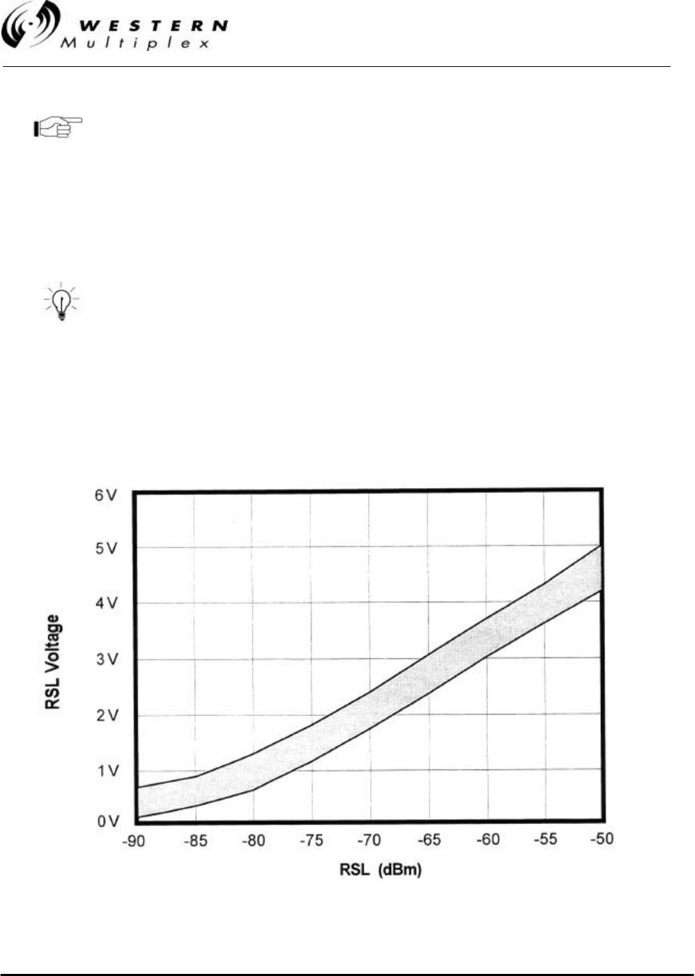
INSTALLATION AND MAINTENANCE MANUAL
LYNX.sc E1 FAMILY
SPREAD SPECTRUM RADIOS
SEPTEMBER 1999
PAGE 3-24 SECTION 3: INSTALLATION & ADJUSTMENTS
Use the Factory Test Data Sheet shipped with your LYNX.sc terminal to
obtain the best estimate of your RSL.
Above 0 dBm RSL, the receiver may produce errors: however this level is rarely likely to be
exceeded. A link budget calculation should be made to calculate the anticipated RSL as described
in Section 3.3.3. During anomalous propagation conditions, the RSL may fade but will not increase
up more than 10 dB (except in unusual very long paths which may fade up by 15 dB).
Antenna alignment should enable the RSL to be peaked to the
level calculated in the link budget. If the RSL is peaked but is
approximately 20 dB below the calculated level, then it is likely
that the antennas are aligned on a sidelobe of the antenna's
radiated signal. In this case, the antennas should be rotated in a
wide arc until the main lobe is located. (Other possible causes of
low RSL are path obstructions, loss in connectors, adapters and
pigtail jumper cables or different antenna polarization at each end
of the link.)
Figure 3-10: Typical RSL Voltage versus Received Signal Level (RSL)
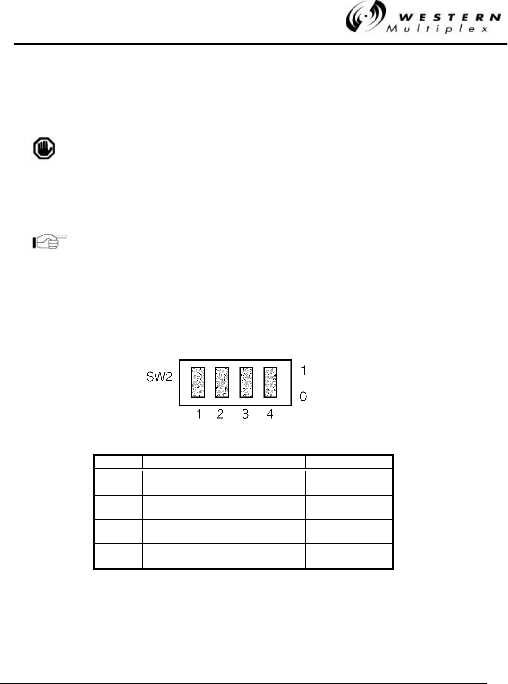
INSTALLATION AND MAINTENANCE MANUAL
LYNX.sc E1 FAMILY
SPREAD SPECTRUM RADIOS
SEPTEMBER 1999
SECTION 3: INSTALLATION & ADJUSTMENTS PAGE 3-25
3.11 CEPT-1 (E1) InterfaceConnection
The CEPT-1 interface connection to the LYNX.sc radio is on the rear panel.
Additional external lightning protection devices are recommended
for the CEPT-1 connections if the radio is installed in an area
prone to lightning.
The CEPT-1 connection to the LYNX.sc is at the data interface on the rear of the shelf. Individual
BNC connectors are used to interface the line transmit and receive functions. Seventy-five (75) ohm
co-axial cables with BNC fittings should be used to connect LYNX.sc to external equipment.
If a balanced 120 ohm connection (RJ45) is required, an
optional balun will provide this interface. If you can not locate
these baluns (balanced/unbalanced) devices, please consult
the factory.
The DATA OUT port provides a bipolar signal (positive and negative pulses) referenced to
ground, with the BNC shield connected to ground.
However, the DATA IN port accepts a similar bipolar signal with the BNC shield normally left OPEN
(floating) in order to eliminate any ground loop problems. If desired, the BNC shield on the DATA IN
port may be grounded using the selector switch SW2.
Position Description Setting
1Grounding Condition Channel 1 0 = Floating
1 = Grounded
2Grounding Condition Channel 2* 0 = Floating
1 = Grounded
3Grounding Condition Channel 3* 0 = Floating
1 = Grounded
4Grounding Condition Channel 4* 0 = Floating
1 = Grounded
* Where applicable
Figure 3-11: CEPT-1 Interface Grounding Switch

INSTALLATION AND MAINTENANCE MANUAL
LYNX.sc E1 FAMILY
SPREAD SPECTRUM RADIOS
SEPTEMBER 1999
PAGE 3-26 SECTION 3: INSTALLATION & ADJUSTMENTS
3.12 DIP Switch Settings
A quick reference guide to all DIP switches is provided in Appendix B.
DIP switch settings are noted by their position, either up (1), or down (0),
not by on/off as may be printed on the DIP switch assembly.
3.12.1 Channel Selection
The LYNX.sc radio offers several frequencies of operation except for the 2.4 GHz 2xT1 and the 5.8
GHz 4xT1 models (see Section 3.5).There are DIP switch segments (typical numbers 5 through 8
on SW3) which define the frequency channel plan of the LYNX.sc radio (refer to Appendix B). The
DIP switches must be set to match the filter assembly that is mounted on the radio. For single and
double capacity models, positions 5,6 and 7 define the frequency channel plan of the radio (e.g. A,
B, C), the last DIP switch defines the transmit channel of the radio (e.g. A1 or A2).
Radios are shipped from the factory with their DIP switch segments set to match the installed filter.
In most cases, no modification of these switches is required.` Also, there are labels on the RF filter
illustrating the correct DIP switch settings. One label is right side up and the other is upside down.
Set the DIP switch settings for the label that is right side up. If a new filter is installed, or the
existing filter is rotated for opposite channel configuration (e.g. A1 to A2), reset the DIP switches to
match the right side up label on the filter. Refer to Section 4.2 for more information.
The radio channel selection is user adjustable by removing and replacing, or reversing the filter
assembly. This allows units of the same radio model to be used as spares for several channels. For
example, if a network of LYNX.sc radios has several radios using all three E1 channel plans at 5.8
GHz, a single spare unit of any channel plan can be used to spare all the radios. If a radio failure
were to occur in the network, the filter assembly of the failed unit would be removed and replace the
filter assembly in the spare radio. The DIP switch segments on the spare may need to change to
match the installed filter and the spare radio could be put into service.
The DIP switch setting must match the filter assembly mounted on the
radio. Also, both radios of a link must have opposite channel plans (e.g.
A1 and A2).
Consult Section 4.2 of this manual for more information on changing RF
channels. Consult Appendix B for proper frequency channel switch
settings.
Other NON-standard frequency plans may be offered in the future. In
these cases, follow the DIP switch setting on the filter label.
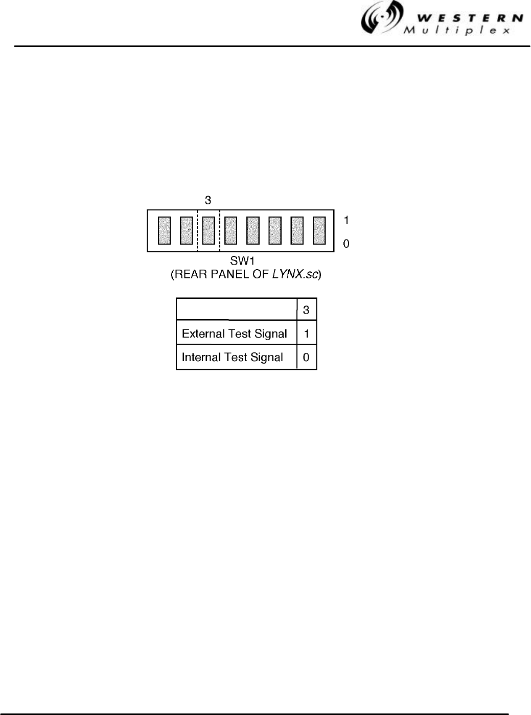
INSTALLATION AND MAINTENANCE MANUAL
LYNX.sc E1 FAMILY
SPREAD SPECTRUM RADIOS
SEPTEMBER 1999
SECTION 3: INSTALLATION & ADJUSTMENTS PAGE 3-27
3.12.2 Loopback Test Signal Selection
The LYNX.sc radio allows loopback operation using an internally generated test signal or using an
externally generated test signal. A single DIP switch segment on SW1 as shown in Figure 3-12,
allows the operator to select the use of either the internal or an external test signal. The factory
setting for loopback mode is internal.
Figure 3-12: Loopback Mode Selection
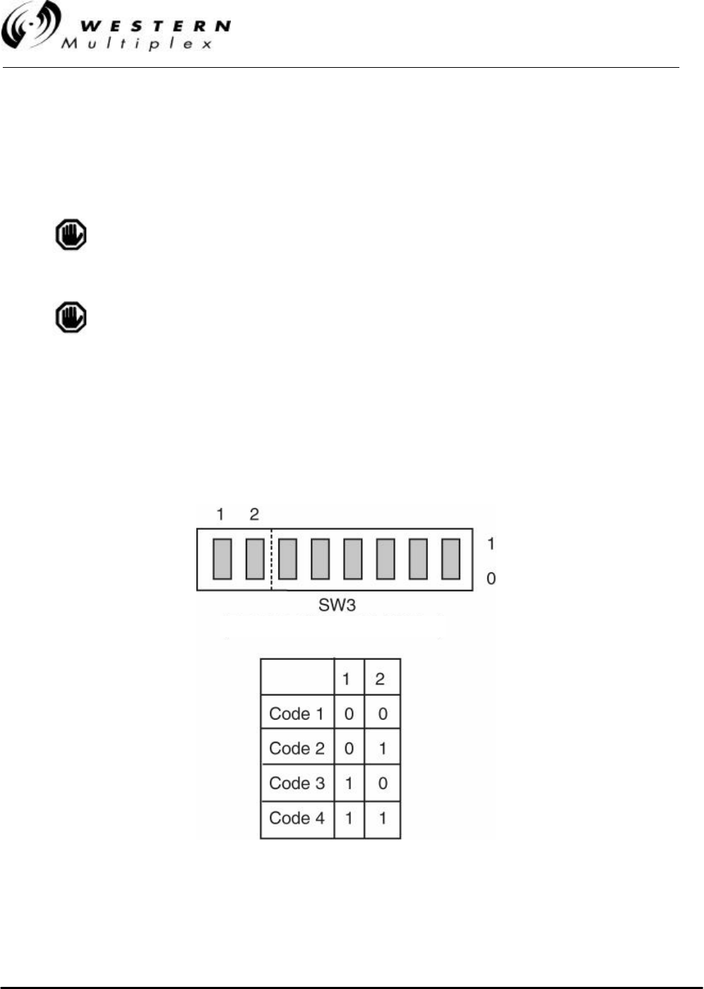
INSTALLATION AND MAINTENANCE MANUAL
LYNX.sc E1 FAMILY
SPREAD SPECTRUM RADIOS
SEPTEMBER 1999
PAGE 3-28 SECTION 3: INSTALLATION & ADJUSTMENTS
3.12.3 Spreading Code Selection
The spreading code is the pseudo-random chip sequence that is mixed with the data to produce the
spread spectrum signal. The spreading code is generated by the LYNX.sc radio internally. Different
codes can be selected using the DIP switches on the LYNX.sc radio rear panel.
The spreading code must be the same for both ends of a radio
link.
The spreading code has no effect with the Model 31850 (4xE1) 3-
channel LYNX.sc.
Spreading codes are all set in the factory to code 1. Should the code need to be changed, then
both ends of the link must be changed.
Changing the spreading code is an out-of-service adjustment. There are two DIP switch segments
on SW3 located on the rear panel which select the spreading codes. See Figure 3-13 for DIP switch
segment settings.
Figure 3-13: Spreading Code Selection
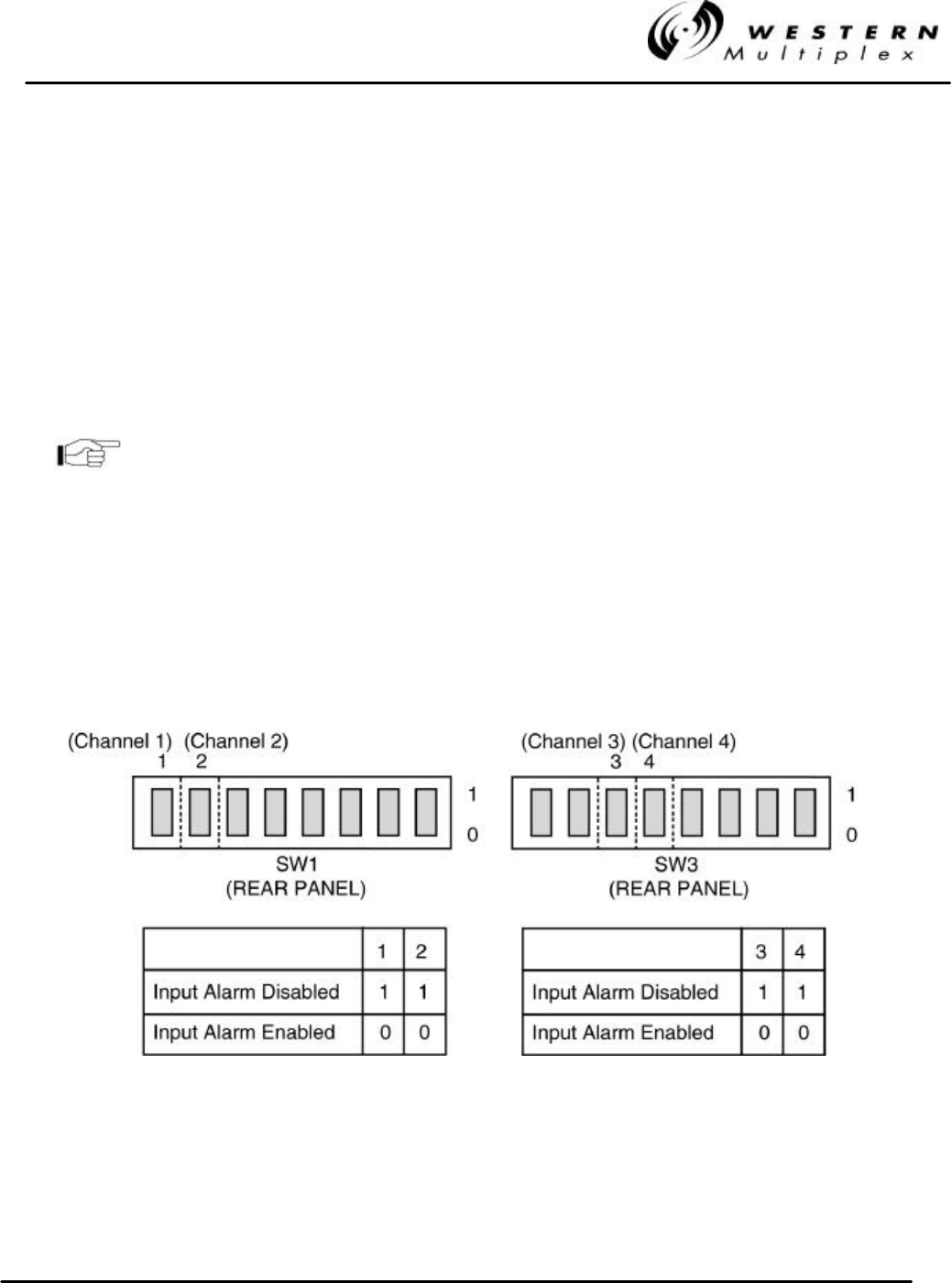
INSTALLATION AND MAINTENANCE MANUAL
LYNX.sc E1 FAMILY
SPREAD SPECTRUM RADIOS
SEPTEMBER 1999
SECTION 3: INSTALLATION & ADJUSTMENTS PAGE 3-29
3.12.4 Input Alarm (Data Loss) Enable/Disable
The LYNX.sc radio provides a capability to enable or disable input alarms (Data Loss). On the front
panel and over the alarm and diagnostic interfaces, an alarm condition is normally generated if there
is no input data signal (E1) to the radio. For example, in the case of the double E1 capacity model,
the radio may have been installed in a location only requiring one E1 signal for traffic while the
second E1 channel has been left idle (for future planned expansion). In this case, it may be
desirable to disable the input alarm to the second channel so that local and remote alarms are not
regularly generated by the (known) lack of this data input. When the network is later expanded to
include traffic on the second E1, this switch can be set to enable the input data alarm condition.
See Figure 3-14 for DIP switch segment settings for the 4xE1 model. Refer to appendix B for all
models.
When a DATA LOSS alarm condition occurs, the LYNX.sc radio
will inject AIS into the incoming data stream, even if the input
alarm has been disabled.
1xE1 and 2xE1 Models:
On SW1, switch segment(s) 1 (and 2) apply to channels 1 and 2 respectively.
4xE1 Model:
On SW3, switch segment 3 applies to Channel 3 input while switch segment 4 applies to Channel 4
input.
Figure 3-14: Input Alarm Disable Switch
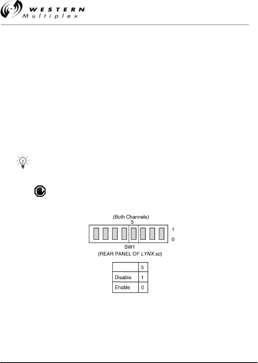
INSTALLATION AND MAINTENANCE MANUAL
LYNX.sc E1 FAMILY
SPREAD SPECTRUM RADIOS
SEPTEMBER 1999
PAGE 3-30 SECTION 3: INSTALLATION & ADJUSTMENTS
3.12.5 AIS Enable/Disable
AIS (Alarm Indication Signal) is the blue code (all 1’s) that keeps the digital line interface active
under data loss conditions. AIS is required by certain equipment to maintain synchronization (for
example, it is required on all leased line circuits). However, it is not required by all equipment (for
example, a CSU/DSU will initiate its own blue code to the line under data loss conditions).
Under test conditions, when measuring receive threshold, for example, it may be necessary, to
disable AIS to facilitate BER measurement.
There is a user selectable DIP switch segment on the rear panel of the LYNX.sc radio that includes
selection of the AIS function (on/off) at the receiver line output. When the AIS is selected (on), the
CEPT-1 signal will send blue code to the line when the received BER exceeds 1 x 10⁻³. This
function is similar to a data “mute” function. When the AIS is disabled (off), no insertion of data will
take place unless an RX SYNC alarm condition occurs. Refer to Figure 3-15 for DIP switch segment
information.
The standard factory setting is to have the demodulator AIS alarm selected ON because it prevents
a severely errored signal (possibly unsynchronized) from being sent out to the line.
It is recommended that AIS be selected ON for normal operation.
It is recommended that AIS be selected OFF for measuring BER
at threshold.
This DIP switch does not affect AIS injection into the
transmitted data stream upon a DATA LOSS condition.
Figure 3-15: AIS Switch

INSTALLATION AND MAINTENANCE MANUAL
LYNX.sc E1 FAMILY
SPREAD SPECTRUM RADIOS
SEPTEMBER 1999
SECTION 3: INSTALLATION & ADJUSTMENTS PAGE 3-31
3.13 System Turn-up to Service
1. Prior to installing the system, it may be desirable to perform a back-to-back test of the
LYNX.sc radio pair. Consult Section 4.9 for further details. Back-to-back testing is a simple
way to verify that the LYNX.sc radios are fully operational before they are installed.
Installation adds several variables (such as antenna alignment) which can lead to system
turn-up delays. Also, during back-to-back testing, the DIP switch settings and some
connections can be tested. This step can eliminate a majority of troubleshooting once the
radios are installed.
A cellular phone or two-way radio system (walkie talkie, CB,
mobile radio) can be very useful during installation. These
can be used for temporary near-end and far-end
communications between the installation personnel at one
site and installation personnel at the other site while installing
the system. These can also be helpful for communication
between a person at the top of a very tall tower and ground
personnel.
The LYNX.sc radio incorporates an internal Orderwire feature
that provides end-to-end “telephone” style communications.
However, the link must be partially operational to use this
feature. In lieu of, or in addition to the use of cellular phones
or two-way radio, this Orderwire feature can also be very useful
for installation, but typically cannot be put into service until
step 8 or 9 of this procedure is completed. See Section 3.14.1
for more details.
2. Perform a general alignment of the antennas on both ends of the path using binoculars,
compass or other related tools. It is important to have the antennas aligned as accurately
as possible before putting radio traffic over the link. This will help in getting the system
running more rapidly. See Section 3.10 for more details.
3. Connect the transmission line to the antenna, and feed it to the LYNX.sc radio location
(see Section 3.9). Connect the opposite end of the transmission line to the N-type female
connector located on the filter assembly which occupies the top half of the LYNX.sc rear
panel. The connection must be terminated into an antenna or a load before DC power is
applied to the radio.
4. Verify that DIP switch settings for frequency channel selection match that of the filter that is
installed on the rear of the radio. Consult 3.12.1 for further details. The far-end radio must
have the same channel plan (e.g. A, B, C) as the near-end radio, and the opposite Tx and
Rx frequencies (e.g. A1 and A2 make up a matched pair of radios).
5. Verify that the DIP switch settings for spreading code are the same for both ends of the
radio link (see Section 3.12.3).
6. With the DC power source active, but not plugged into the LYNX.sc radio, using a
voltmeter, confirm that the DC mating connector has the proper power connections in

INSTALLATION AND MAINTENANCE MANUAL
LYNX.sc E1 FAMILY
SPREAD SPECTRUM RADIOS
SEPTEMBER 1999
PAGE 3-32 SECTION 3: INSTALLATION & ADJUSTMENTS
accordance with Section 3.7. Verify the polarity and the absolute voltage on all pins. Verify
ground connection for power.
7. Connect power to the LYNX.sc radio. Verify that the Front Panel “ON” LED indication is
illuminated. This confirms that power has been properly applied.
Ensure that the RF Antenna port connection is properly
terminated before applying power to the LYNX.sc terminal, as in
step 3.
When the LYNX.sc radio is initially powered-on, some alarm
conditions may be present. This is normal and alarms can be
ignored at this time.
8. Place a voltmeter across the GND and PWR front panel test points. See Figure 3-16 and 3-
17 for voltage setting information and Table 3-C for typical output power levels for given
cable lengths where EIRP limits apply. If necessary, use a small screwdriver at the front
panel receptacle to adjust the output power of the local transmitter in accordance with the
path analysis calculations. The recessed potentiometer is rotated clockwise to increase
transmit output power and counter clockwise to decrease transmit output power. After
verifying correct setting of the transmit output power, disconnect the voltmeter. Place the
cover cap found in the installation accessory kit over the front panel receptacle.
The LYNX.sc radio requires professional installation. With some
LYNX.sc models, in certain countries, there may be Effective
Isotropic Radiated Power (EIRP) limits which dictate the
maximum output power that the LYNX.sc radio can transmit given
the transmission line loss and the gain of the antenna. Consult
with appropriate government agencies or Western Multiplex if
there is any question regarding maximum output power allowed.
In the USA, 5.8 GHz models may be operated at full power. 2.4
GHz models may require a power reduction of 1 dB from +30 dBm
input power, as measured at the antenna feed, for every 3 dB that
the antenna gain exceeds +6 dB. See Section 3.3.3 and Tables 3-
C or 3-D for more details.
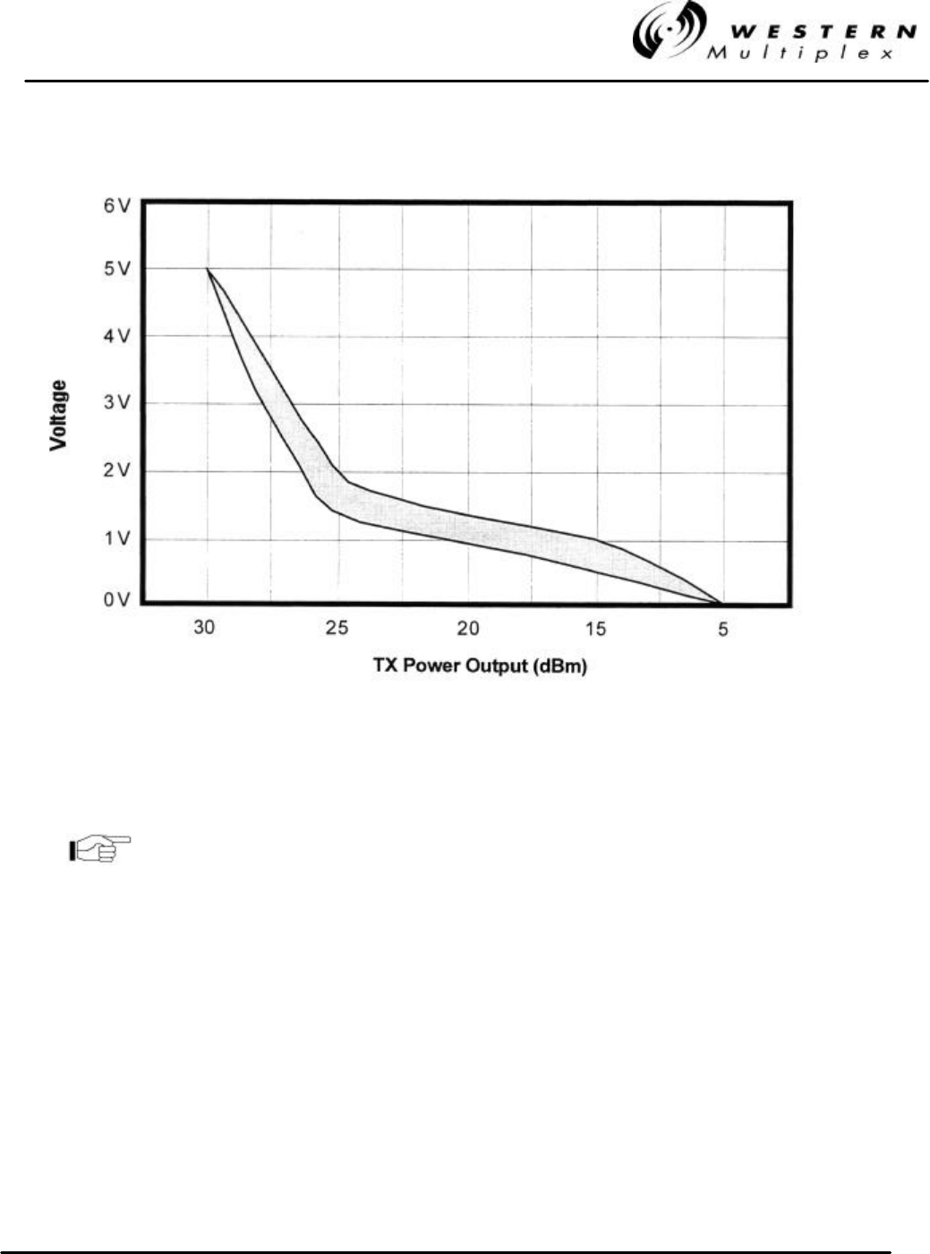
INSTALLATION AND MAINTENANCE MANUAL
LYNX.sc E1 FAMILY
SPREAD SPECTRUM RADIOS
SEPTEMBER 1999
SECTION 3: INSTALLATION & ADJUSTMENTS PAGE 3-33
Figure 3-16: Typical RF Output Power versus PWR Voltage, 2.4 GHz Models
Use the LYNX.sc Factory Test Data sheet to determine more
precisely the voltage corresponding to the RF output power.
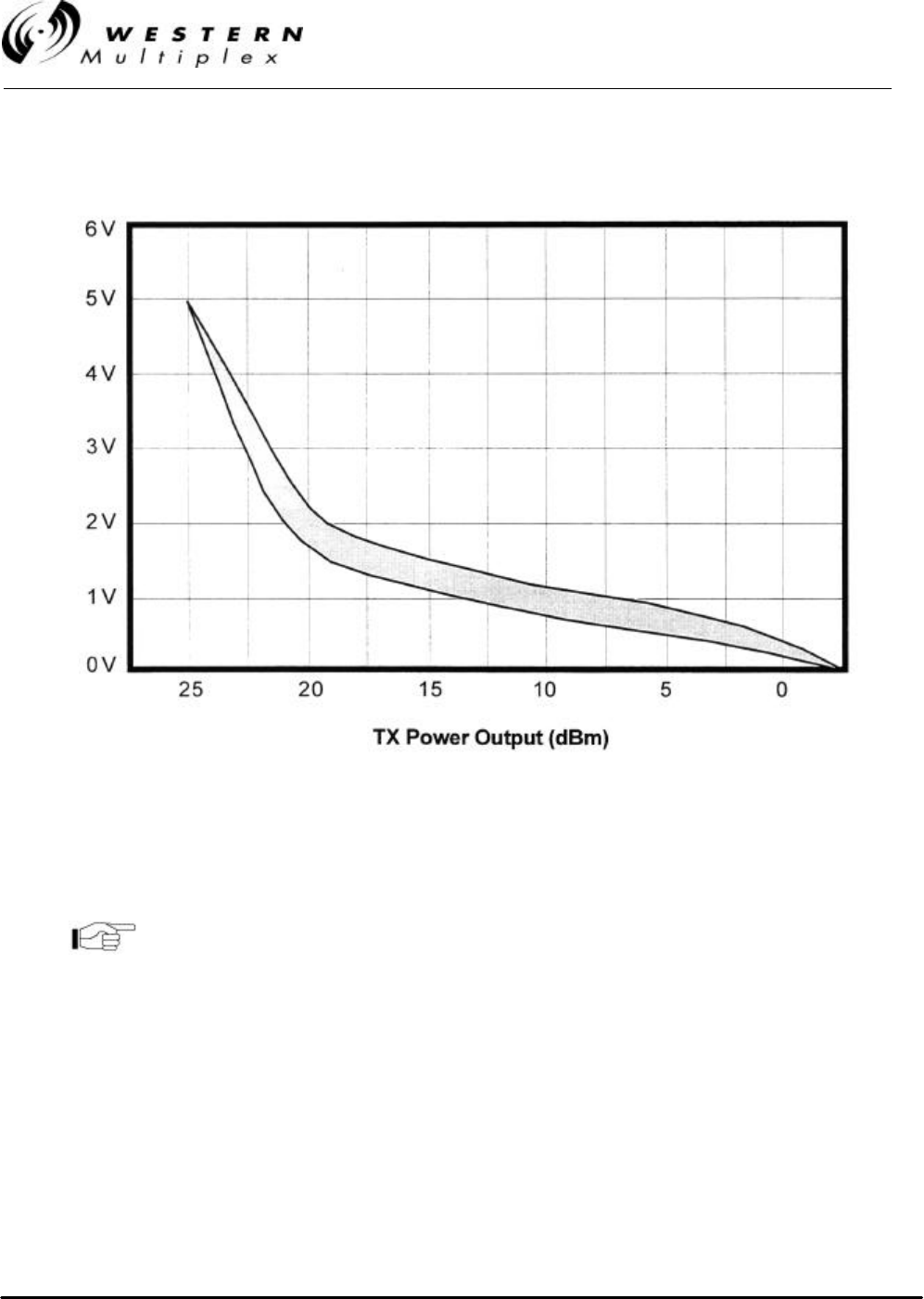
INSTALLATION AND MAINTENANCE MANUAL
LYNX.sc E1 FAMILY
SPREAD SPECTRUM RADIOS
SEPTEMBER 1999
PAGE 3-34 SECTION 3: INSTALLATION & ADJUSTMENTS
Figure 3-17: Typical RF Output Power versus PWR Voltage, 5.8 GHz Models
Use the LYNX.sc Factory Test Data sheet to determine more
precisely the voltage corresponding to the RF output power.

INSTALLATION AND MAINTENANCE MANUAL
LYNX.sc E1 FAMILY
SPREAD SPECTRUM RADIOS
SEPTEMBER 1999
SECTION 3: INSTALLATION & ADJUSTMENTS PAGE 3-35
For precision measurement of transmit output power, it is best to
connect an RF power meter to the antenna port. The PWR port
voltage may not provide enough precision. This is especially
important where EIRP limits apply to the installation.
In cases of no EIRP limits, the radio transmitter output power
can be adjusted to maximum for installation, except for very
short paths using very high gain antennas, where excessive
power may not be advised.
Don’t forget that the RF output port should be terminated at all
times when power is applied to the LYNX.sc radio. Therefore,
disconnect power to the radio before connecting a power meter
and reapply power once connected. Often, an RF power meter
may have a limit to the input power that it can measure without
damage. It is advised to place a calibrated fixed value RF
attenuator (typically 20 dB or more) between the LYNX.sc radio
and the power meter to assure proper operation and safety for the
RF power meter. The value of this fixed attenuation can then be
added to the value of the RF power meter reading to obtain the
actual LYNX.sc radio transmitter output power.
9. Connect a voltmeter across the GND and RSL front panel test points. This voltage reading
corresponds to the Received Signal Level (RSL) of the near-end radio. In other words, RSL
is the “amount” of signal the near-end radio is receiving from the far-end radio. Since the
antennas have not been finely aligned, it is not expected at this time that the RSL will read
very high. However, at this point it can be verified that some communication is taking place
between the two LYNX.sc terminals. Use the RSL voltage reading to align the antennas.
Align one antenna at a time in accordance with Section 3.10. Complete alignment of both
ends of the radio link before going further.
The RSL voltage output on the radio's front panel will output a
voltage range over the full receiving capability of the radio
(approximately 10 VDC at 0 dBm to 0.0 VDC at threshold).
The LYNX.sc radio has a unique feature of allowing measurement of the far-end RSL from the near-
end radio. This is only possible if the LYNX.sc radios are communicating (the RSL is above
threshold). The far-end RSL can be used to verify that adjustments to local antenna alignment are
corresponding to the far-end radio reception. Far-end RSL is measured by pressing and holding the
DISPLAY FAR END front panel button. While this button is held, the RSL voltage indicates the RSL
of the far-end radio. RSL of both ends should be verified to be within approximately 2 dB of predicted
value (see Section 3.3.3). There are several factors that can contribute to low RSL:
-Incorrect antenna alignment (aligned on a lobe and not on the main signal)
-Improper polarization alignment of antennas (horizontal vs. vertical)
-Transmission line problems (loose connections, bent or damaged cables, lossy adapters)
-Path obstructions (trees, buildings, hills, etc.)
-Path clearance (line-of-sight, earth curvature, Fresnel zone, diffraction and partial

INSTALLATION AND MAINTENANCE MANUAL
LYNX.sc E1 FAMILY
SPREAD SPECTRUM RADIOS
SEPTEMBER 1999
PAGE 3-36 SECTION 3: INSTALLATION & ADJUSTMENTS
obstruction)
-Weather (inversion layers, ducting and multipath)
-Antenna feed (coaxial/connector) problem
The LYNX.sc radio requires professional installation. Don’t
forget that the transmitter output power adjustment on the
LYNX.sc radio effects the RSL. Depending on EIRP limits (if
any), path distance, and antenna gain, you may need to adjust
the output transmit power to the proper level before putting the
radios in service.
If radio synchronization has been established, the radio link
may be able to provide some limited communications over the
link. It can be helpful to establish voice communications from
one end of the radio link to the other using the Orderwire
feature of the LYNX.sc radio. See Section 3.14.1 for details.
If RSL is lower than anticipated, recheck the path clearance and transmission line as these are the
typical causes of low RSL. Radio operations can be verified by connecting radios back-to-back with
attenuators (40-60 dB), (see Section 4.9). If the problem remains, consult Section 4 of this manual
for troubleshooting techniques which will help determine the source of the problem.
10. Once RSL is verified to be near the predicted value, the radio link is ready for data. You
may verify error-free operation by using the loopback function, as described in Section
3.13.2 or BER testing, as described in Section 4.10. If the link is not error-free, see Section
4.7 for troubleshooting guidelines.
11. Once radio performance is verified and acceptable, with loopback mode turned off (press
the ENABLE button, the LED will turn off), the LYNX.sc radios can now be put into service
with the intended E1 traffic. Connect the E1 signal to the CEPT-1 Interface BNC connector.
Refer to Section 3.11 for configurations of these connections. With E1 traffic applied in both
directions, all front panel LEDs, except for POWER and any unused E1 ports, will be off. If
LEDs are lit, consult Section 4 of this manual.
12. Now that the link is operational, other services can be connected including Orderwire,
Diagnostics, Alarms and Aux Data (Service Channel). Consult Section 3.14 for details on
these connections.

INSTALLATION AND MAINTENANCE MANUAL
LYNX.sc E1 FAMILY
SPREAD SPECTRUM RADIOS
SEPTEMBER 1999
SECTION 3: INSTALLATION & ADJUSTMENTS PAGE 3-37
TRANSMITTER POWER (dBm) . .
Feeder Feeder 2.4 GHz, 1/2" Coax 2.4 GHz, 7/8" Coax 5.8 GHz, 1/2" Coax 5.8 GHz, EW52 Waveguide
Length Length 4' Dish 6' Dish 8' Dish 4' Dish 6' Dish 8' Dish 2' Dish 4' Dish 6' Dish 8' Dish 2' Dish 4' Dish 6' Dish 8' Dish
Meters Feet
3.0 10 9.4 4.9 3.4 9.2 4.7 3.2 7.7 1.7 -1.3 -4.3 7.1 1.1 -1.9 -4.9
6.1 20 9.8 5.3 3.8 9.4 4.9 3.4 8.3 2.3 -0.7 -3.7 7.3 1.3 -1.7 -4.7
9.1 30 10.1 5.6 4.1 9.7 5.2 3.7 9.0 3.0 0.0 -3.0 7.4 1.4 -1.6 -4.6
12.2 40 10.5 6.0 4.5 9.9 5.4 3.9 9.6 3.6 0.6 -2.4 7.5 1.5 -1.5 -4.5
15.2 50 10.9 6.4 4.9 10.1 5.6 4.1 10.3 4.3 1.3 -1.7 7.7 1.7 -1.3 -4.3
18.3 60 11.3 6.8 5.3 10.3 5.8 4.3 11.0 5.0 2.0 -1.0 7.8 1.8 -1.2 -4.2
21.3 70 11.7 7.2 5.7 10.5 6.0 4.5 11.6 5.6 2.6 -0.4 7.9 1.9 -1.1 -4.1
24.4 80 12.0 7.5 6.0 10.8 6.3 4.8 12.3 6.3 3.3 0.3 8.0 2.0 -1.0 -4.0
27.4 90 12.4 7.9 6.4 11.0 6.5 5.0 12.9 6.9 3.9 0.9 8.2 2.2 -0.8 -3.8
30.5 100 12.8 8.3 6.8 11.2 6.7 5.2 13.6 7.6 4.6 1.6 8.3 2.3 -0.7 -3.7
33.5 110 13.2 8.7 7.2 11.4 6.9 5.4 14.3 8.3 5.3 2.3 8.4 2.4 -0.6 -3.6
36.6 120 13.6 9.1 7.6 11.6 7.1 5.6 14.9 8.9 5.9 2.9 8.6 2.6 -0.4 -3.4
39.6 130 13.9 9.4 7.9 11.9 7.4 5.9 15.6 9.6 6.6 3.6 8.7 2.7 -0.3 -3.3
42.7 140 14.3 9.8 8.3 12.1 7.6 6.1 16.2 10.2 7.2 4.2 8.8 2.8 -0.2 -3.2
45.7 150 14.7 10.2 8.7 12.3 7.8 6.3 16.9 10.9 7.9 4.9 9.0 3.0 0.0 -3.0
48.8 160 15.1 10.6 9.1 12.5 8.0 6.5 17.6 11.6 8.6 5.6 9.1 3.1 0.1 -2.9
51.8 170 15.5 11.0 9.5 12.7 8.2 6.7 18.2 12.2 9.2 6.2 9.2 3.2 0.2 -2.8
54.9 180 15.8 11.3 9.8 13.0 8.5 7.0 18.9 12.9 9.9 6.9 9.3 3.3 0.3 -2.7
57.9 190 16.2 11.7 10.2 13.2 8.7 7.2 19.5 13.5 10.5 7.5 9.5 3.5 0.5 -2.5
61.0 200 16.6 12.1 10.6 13.4 8.9 7.4 20.2 14.2 11.2 8.2 9.6 3.6 0.6 -2.4
64.0 210 17.0 12.5 11.0 13.6 9.1 7.6 20.9 14.9 11.9 8.9 9.7 3.7 0.7 -2.3
67.1 220 17.4 12.9 11.4 13.8 9.3 7.8 21.5 15.5 12.5 9.5 9.9 3.9 0.9 -2.1
70.1 230 17.7 13.2 11.7 14.1 9.6 8.1 22.2 16.2 13.2 10.2 10.0 4.0 1.0 -2.0
73.2 240 18.1 13.6 12.1 14.3 9.8 8.3 22.8 16.8 13.8 10.8 10.1 4.1 1.1 -1.9
76.2 250 18.5 14.0 12.5 14.5 10.0 8.5 MAX 17.5 14.5 11.5 10.3 4.3 1.3 -1.7
79.2 260 18.9 14.4 12.9 14.7 10.2 8.7 MAX 18.2 15.2 12.2 10.4 4.4 1.4 -1.6
82.3 270 19.3 14.8 13.3 14.9 10.4 8.9 MAX 18.8 15.8 12.8 10.5 4.5 1.5 -1.5
85.3 280 19.6 15.1 13.6 15.2 10.7 9.2 MAX 19.5 16.5 13.5 10.6 4.6 1.6 -1.4
88.4 290 20.0 15.5 14.0 15.4 10.9 9.4 MAX 20.1 17.1 14.1 10.8 4.8 1.8 -1.2
91.4 300 20.4 15.9 14.4 15.6 11.1 9.6 MAX 20.8 17.8 14.8 10.9 4.9 1.9 -1.1
94.5 310 20.8 16.3 14.8 15.8 11.3 9.8 MAX 21.5 18.5 15.5 11.0 5.0 2.0 -1.0
97.5 320 21.2 16.7 15.2 16.0 11.5 10.0 MAX 22.1 19.1 16.1 11.2 5.2 2.2 -0.8
100.6 330 21.5 17.0 15.5 16.3 11.8 10.3 MAX 22.8 19.8 16.8 11.3 5.3 2.3 -0.7
103.6 340 21.9 17.4 15.9 16.5 12.0 10.5 MAX MAX 20.4 17.4 11.4 5.4 2.4 -0.6
106.7 350 22.3 17.8 16.3 16.7 12.2 10.7 MAX MAX 21.1 18.1 11.6 5.6 2.6 -0.4
109.7 360 22.7 18.2 16.7 16.9 12.4 10.9 MAX MAX 21.8 18.8 11.7 5.7 2.7 -0.3
112.8 370 23.1 18.6 17.1 17.1 12.6 11.1 MAX MAX 22.4 19.4 11.8 5.8 2.8 -0.2
115.8 380 23.4 18.9 17.4 17.4 12.9 11.4 MAX MAX MAX 20.1 11.9 5.9 2.9 -0.1
118.9 390 23.8 19.3 17.8 17.6 13.1 11.6 MAX MAX MAX 20.7 12.1 6.1 3.1 0.1
121.9 400 24.2 19.7 18.2 17.8 13.3 11.8 MAX MAX MAX 21.4 12.2 6.2 3.2 0.2
Table 3-C: Transmitter Output Power Adjustment, +6 dBW EIRP Installations
(Such as Canada)

INSTALLATION AND MAINTENANCE MANUAL
LYNX.sc E1 FAMILY
SPREAD SPECTRUM RADIOS
SEPTEMBER 1999
PAGE 3-38 SECTION 3: INSTALLATION & ADJUSTMENTS
Feeder Feeder TRANSMITTER POWER (dBm)
Length Length 2.4 GHz, 1/2" Coax 2.4 GHz, 7/8" Coax
Meters Feet 4' Dish 6' Dish 8' Dish 4' Dish 6' Dish 8' Dish
3.0 10 23.4 22.0 21.2 23.2 21.9 21.1
6.1 20 23.8 22.4 21.6 23.5 22.1 21.3
9.1 30 24.1 22.8 22.0 23.7 22.4 21.5
12.2 40 24.5 23.2 22.4 23.9 22.6 21.8
15.2 50 24.9 23.6 22.7 24.2 22.8 22.0
18.3 60 25.3 23.9 23.1 24.4 23.0 22.2
21.3 70 25.7 24.3 23.5 24.6 23.3 22.4
24.4 80 26.0 24.7 23.9 24.8 23.5 22.7
27.4 90 26.4 25.1 24.3 25.1 23.7 22.9
30.5 100 26.8 25.5 24.6 25.3 24.0 23.1
33.5 110 27.2 25.8 25.0 25.5 24.2 23.4
36.6 120 27.6 26.2 25.4 25.8 24.4 23.6
39.6 130 27.9 26.6 25.8 26.0 24.7 23.8
42.7 140 28.3 27.0 26.2 26.2 24.9 24.1
45.7 150 28.7 27.4 26.5 26.5 25.1 24.3
48.8 160 29.1 27.7 26.9 26.7 25.3 24.5
51.8 170 29.5 28.1 27.3 26.9 25.6 24.7
54.9 180 29.8 28.5 27.7 27.1 25.8 25.0
57.9 190 MAX 28.9 28.1 27.4 26.0 25.2
61.0 200 MAX 29.3 28.4 27.6 26.3 25.4
64.0 210 MAX 29.6 28.8 27.8 26.5 25.7
67.1 220 MAX MAX 29.2 28.1 26.7 25.9
70.1 230 MAX MAX 29.6 28.3 27.0 26.1
73.2 240 MAX MAX MAX 28.5 27.2 26.4
76.2 250 MAX MAX MAX 28.8 27.4 26.6
79.2 260 MAX MAX MAX 29.0 27.6 26.8
82.3 270 MAX MAX MAX 29.2 27.9 27.0
85.3 280 MAX MAX MAX 29.4 28.1 27.3
88.4 290 MAX MAX MAX 29.7 28.3 27.5
91.4 300 MAX MAX MAX 29.9 28.6 27.7
94.5 310 MAX MAX MAX MAX 28.8 28.0
97.5 320 MAX MAX MAX MAX 29.0 28.2
100.6 330 MAX MAX MAX MAX 29.3 28.4
103.6 340 MAX MAX MAX MAX 29.5 28.7
106.7 350 MAX MAX MAX MAX 29.7 28.9
109.7 360 MAX MAX MAX MAX 29.9 29.1
112.8 370 MAX MAX MAX MAX MAX 29.3
115.8 380 MAX MAX MAX MAX MAX 29.6
118.9 390 MAX MAX MAX MAX MAX 29.8
121.9 400
MAX
MAX
MAX
MAX
MAX
30.0
Table 3-D: Transmitter Output Power Adjustment for 2.4 GHz, USA Installations

INSTALLATION AND MAINTENANCE MANUAL
LYNX.sc E1 FAMILY
SPREAD SPECTRUM RADIOS
SEPTEMBER 1999
SECTION 3: INSTALLATION & ADJUSTMENTS PAGE 3-39
3.13.1 Output Power Adjustment
The LYNX.sc radio requires professional installation. In certain cases, it is necessary to adjust the
output power from the factory setting, for example:
vto meet EIRP (effective isotropic radiated power) limits, such as +6 dBW in Canada.
vto meet transmitter output limits in the 2.4 GHz band for USA installations.
vto avoid exceeding the maximum far-end RSL of 0 dBm.
vto coordinate a hub or repeater location.
To ensure maximum protection of the radio circuits, always
ensure the antenna connector is terminated when power is
applied.
For precise measurement of transmitter power, a calibrated RF power meter (such as the HP 435B
with Power Sensor HP8481) is recommended. This power sensor can be connected directly to the
output of the radio without exceeding the power rating. With some power meters, it may be
necessary to place a calibrated in-line fixed attenuator between the radio antenna port and the
power meter so as to not exceed the power meter’s maximum input level. Thruline power meters do
not operate at LYNX.sc RF frequencies.
If adjusting the output power to meet an EIRP limit, it will be first necessary to calculate the overall
system gains and losses, including feeder losses for the type of transmission line installed and the
antenna gain. Also refer to Table 3-C or 3-D for transmitter output power settings where installed
with various transmission line lengths and antenna sizes. You may determine the radio transmit
power for EIRP limited installations by the following equation:
Tx Power (dBm) = EIRP Limit(dBm) + Feeder Loss(dB) - Antenna Gain(dB)
In the USA, 2.4 GHz models have an output limit which is determined by:
Tx Power (dBm) = 30 - [(Antenna Gain - 6)/ 3] + Feeder Loss
Output power may be adjusted using a small screwdriver and rotating the potentiometer which is
recessed behind the front panel. Clockwise rotation increases output power while counter-clockwise
rotation decreases output power.
In lieu of a calibrated RF power meter, the PWR test port voltage can be used to estimate the
output power. Figures 3-16 & 3-17 illustrate the voltage reading for various output power levels. The
factory test data sheet should be used to establish a more precise setting of this adjustment.
After setting the correct output power, place the cover cap
found in the installation accessory kit over the front panel
receptacle.

INSTALLATION AND MAINTENANCE MANUAL
LYNX.sc E1 FAMILY
SPREAD SPECTRUM RADIOS
SEPTEMBER 1999
PAGE 3-40 SECTION 3: INSTALLATION & ADJUSTMENTS
3.13.2 Loopback/BER Testing
When a pair of LYNX.sc radios are installed and communicating with each other, a loopback or
BER test can be performed to evaluate the link performance.
The LYNX.sc uses an internal test signal for loopback. Alternatively, an external test signal can be
injected, as described in Section 3.12.4. Any E1 test pattern may be used to make measurements
at one end of the link, provided the test sequence contains adequate 1’s density, which is no more
than 15 consecutive zeros.
A 215-1, QRSS or 3 in 24 test may be used. However a 223-1 test
will violate the 1’s density requirement.
To loop around the far-end radio, press ENABLE and hold for approximately 3 seconds. then
release the Loopback ENABLE button on the front panel of the near-end radio. The ENABLE LED
should now be blinking.
If the ENABLE loopback button LED is illuminated and not
blinking, this means the far-end radio has initiated loopback
(either manually or through the DIAGNOSTICS port).
When loopback is enabled using the internal test signal, the ERROR LED should not illuminate if
the path is operating error-free. If the ERROR LED illuminates, this means that at least one bit error
has occurred.
The DATA LOSS LED will illuminate if the external test signal mode has been selected (see
Section 3.12.4) and there is no external test signal present at any of the CEPT-1 ports. When using
external test mode and an external test signal, the ERROR LED function does not apply. In external
test mode the ERROR LED will not illuminate, even when errors are present.

INSTALLATION AND MAINTENANCE MANUAL
LYNX.sc E1 FAMILY
SPREAD SPECTRUM RADIOS
SEPTEMBER 1999
SECTION 3: INSTALLATION & ADJUSTMENTS PAGE 3-41
An external BER test set is required for statistical BER analysis. Disconnect all external CEPT-1
signals and connect the BER test set to the input and output BNC connectors. Select external test
mode (see Section 3.12.2) and initiate loopback using the ENABLE loopback button. Now the BER
test can be initiated. Section 4.10 describes BER testing in more detail.
Loopback may be turned off at either end of the link by simply
pressing the ENABLE button at either end.
If two BER test sets are used to measure the link performance
(one at each end) separately in each direction, frame slips will
occur unless the BER test sets are synchronized with one test
set as the master and the other as the slave.
For multiple capacity radio models, repeat all operations for the
other channels if desired.
For multiple capacity radio models, only one loopback channel
may be used at any one time. Loopback cannot be performed on
more than one channel.
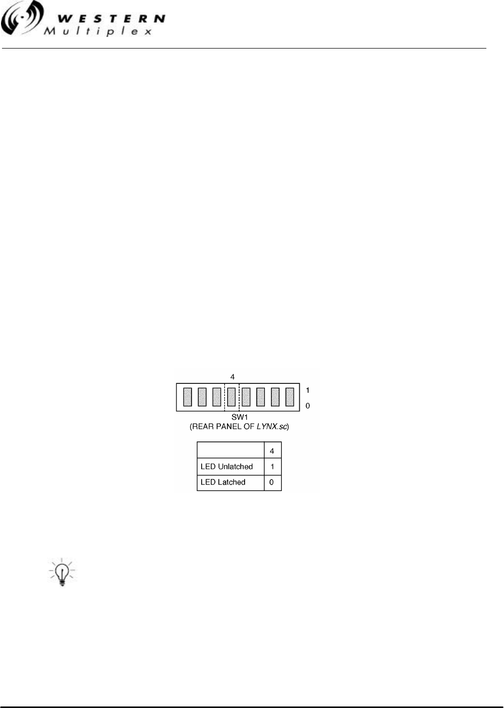
INSTALLATION AND MAINTENANCE MANUAL
LYNX.sc E1 FAMILY
SPREAD SPECTRUM RADIOS
SEPTEMBER 1999
PAGE 3-42 SECTION 3: INSTALLATION & ADJUSTMENTS
3.13.3 Error LED Mode Selection
The ERROR LED illuminates if any errors are present in the data stream during loopback. This LED
is only functional when using the internal test signal.
The default mode for this LED is “latched.” That is, when a single error occurs, the LED illuminates
and stays lit until loopback is turned off. This mode is especially useful for long term (overnight)
testing, or any time that an operator is not watching the radio during loopback testing.
There is an optional mode for this LED which is “unlatched.” This allows the user to “view” the error
rate. In this mode, the LED will flash on each time a single or multiple error occurs. The LED turns
off if no further errors occur. This mode can be useful if a BER test set is not available and the user
wishes to determine the nature of any error conditions (bursting, dribbling, occasional).
In “unlatched” mode, when any errors occur, the ERROR LED will illuminate for a minimum of one
second. If errors continue within this one second interval, the LED will remain on until there are no
errors for 1 second.
The two modes for this LED are selected by a rear panel DIP switch, as shown in Figure 3-18.
Figure 3-18: Error LED Mode Selection
In the LED unlatch mode, after 100 errors the ERROR LED will
remain lit to indicate excessive errors.

INSTALLATION AND MAINTENANCE MANUAL
LYNX.sc E1 FAMILY
SPREAD SPECTRUM RADIOS
SEPTEMBER 1999
SECTION 3: INSTALLATION & ADJUSTMENTS PAGE 3-43
3.14 Additional Connections
There are additional customer connections which are optional and are not required to make the
LYNX.sc operational but may prove useful.
3.14.1 Orderwire Connection and Address Selection
Orderwire is a “telephone” type wayside service which allows users of the LYNX.sc radio to
establish voice communications from one radio to another, either directly to the companion far-end,
or through a repeater configuration, or several repeater configurations.
Telephone connection specifications:
REN (Ringer Equivalency Number) 1.0 B
DTMF tones within ±1.5% of nominal freq.
Ringing Voltage 48 VDC, typical
(Ringing voltage is adequate for modern solid state ringers,
NOT for the older mechanical type ringers)
This Orderwire service does not affect the normal radio transmission of E1 traffic. Refer to Section
2.3.5 for the telephone specifications. For simple near-end to far-end communications, follow the
steps below:
1. Using a small screwdriver, set the address of both terminals by rotating the address rotary
selection switches on the rear panel of the LYNX.sc radio. The address is a two digit number
(from 01 to 99). Each LYNX.sc terminal in the network should have a unique address. This
address acts like a “phone number” for other users to call a particular terminal. Each LYNX.sc
terminal should have a unique address.
Radio pairs (links) are shipped from the factory with addresses set to
01 or 02. Therefore, if only one pair is being used, address selection
may not be necessary. Also, in a connected spur network, it may be
desirable to maintain orderwire telephone addresses between 01 and 08
because the address doubles as the NMS/TBOS net address which is
limited to the addresses 01 through 08 (see Section 3.14.3 for more
information).
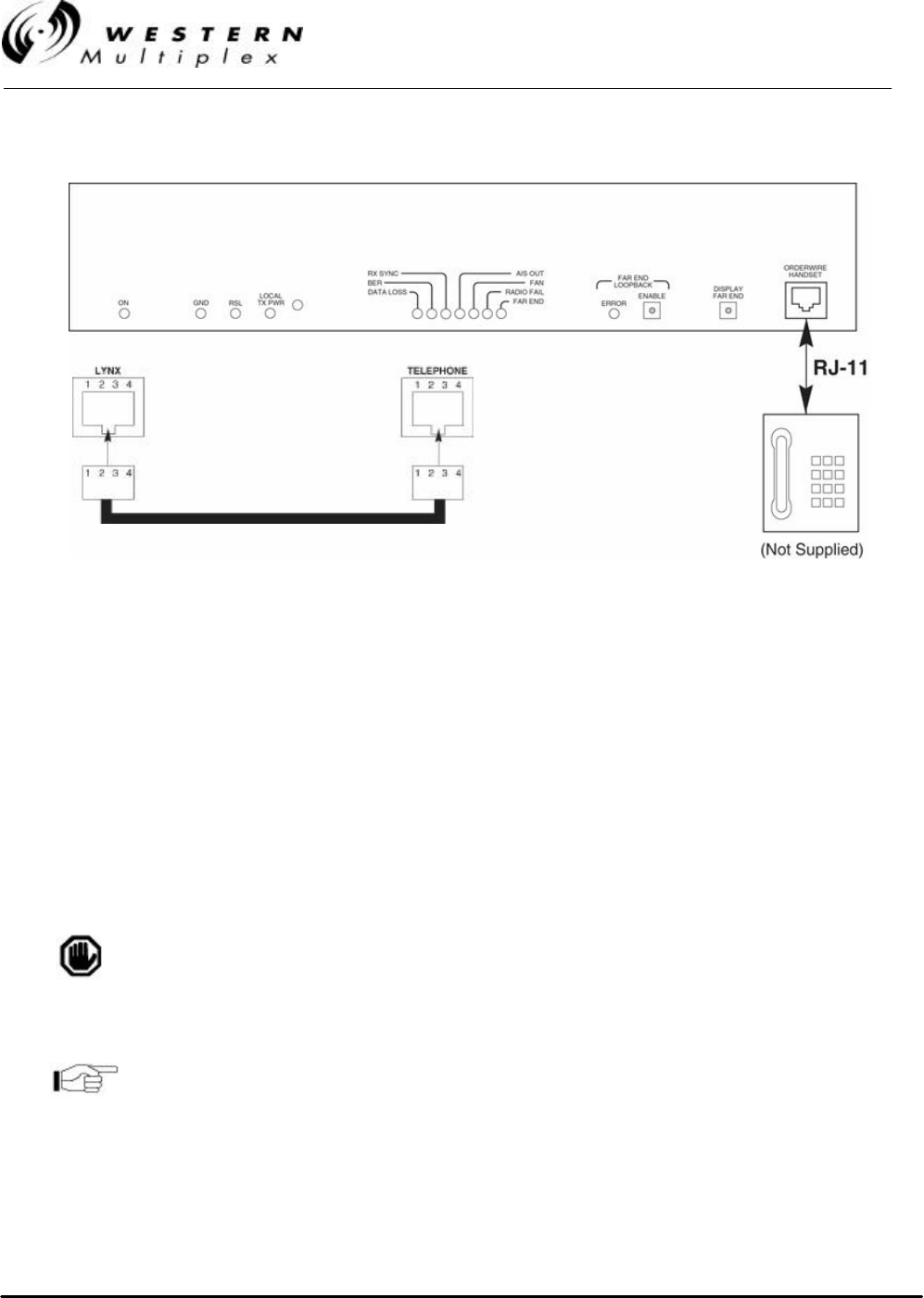
INSTALLATION AND MAINTENANCE MANUAL
LYNX.sc E1 FAMILY
SPREAD SPECTRUM RADIOS
SEPTEMBER 1999
PAGE 3-44 SECTION 3: INSTALLATION & ADJUSTMENTS
Figure 3-19: RJ-11 Orderwire Telephone Connection
2. Using a standard RJ-11 telephone cable, connect a standard electronic telephone (a touch
tone phone, complete with dialer; a handset by itself will not work) to the Orderwire
connector on the LYNX.sc front panel. This connector is wired identically to a standard two-
wire telephone jack, see Figure 3-19 for details.
3. With a telephone connected to each LYNX.sc terminal on opposite ends of the link, either
telephone can be used to “dial-up” the far-end location. Simply pick up the handset of the
near-end telephone and dial the two-digit address of the far-end LYNX.sc terminal. The far-
end terminal’s internal ringer and the connected telephone will ring, and if answered, two-
way full-duplex voice communication is established.
If using the Orderwire or Network management functions, all
LYNX.sc radios connected must have unique address settings
(telephone numbers).
The orderwire address is set by two rotary switches on the rear
panel of the LYNX.sc radio. Use as small screwdriver to select
the orderwire address (01 through 99).
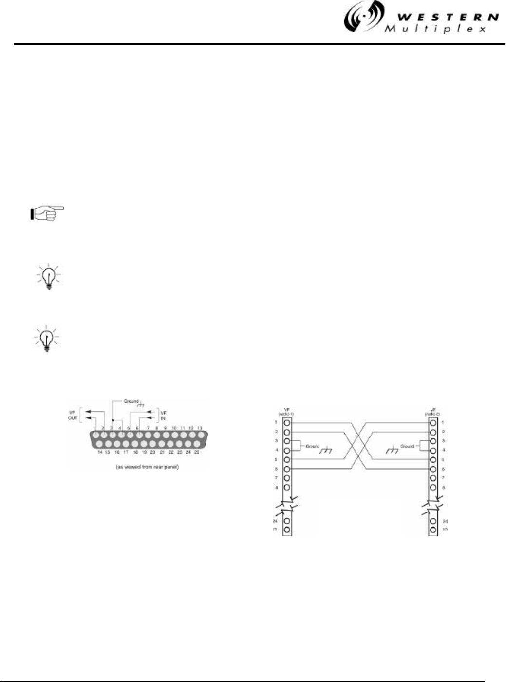
INSTALLATION AND MAINTENANCE MANUAL
LYNX.sc E1 FAMILY
SPREAD SPECTRUM RADIOS
SEPTEMBER 1999
SECTION 3: INSTALLATION & ADJUSTMENTS PAGE 3-45
4. If the LYNX.sc radios are connected in a repeater configuration, Orderwire services can be
established to all LYNX.sc terminals in the network by implementing a connection of their rear-
panel connectors between repeater terminals. At the repeater site, a cable can be connected to
the two LYNX.sc terminals between their rear panel VF 25-pin connectors as shown in Figure
3-20. With this cable in place, the Orderwire function will operate at terminals at each end of the
repeater and at the repeater site. This function can be continued through several repeater sites
if desired. For hub connections of 3 or more LYNX.sc radios at the same site, an external 4-
wire bridge is required to connect all radios to the orderwire.
The orderwire system can be integrated with orderwire equipment
supported by many other vendors. If your existing orderwire
network uses 2 digit addressing, and 0 dBm VF interface, it can
be connected to a LYNX.sc as shown in Figure 3-20.
Dialing a V (star key) on the orderwire telephone implements an
“all call” feature which rings all connected radios. Also, if a phone
anywhere in the connected network has accidentally been left off-
hook, the # (pound key) key can be used to mute all off-hook
handsets until they are placed on and off hook again.
The orderwire operates like a “party line”. All telephones provide
communication to all other telephones in the connected network.
Even if a particular telephone does not ring, it can still be used to
talk and listen to any ongoing orderwire activity if the orderwire is
in use at other terminal locations.
Figure 3-20: VF Port Connection
VF Connector OrderWire
Connection
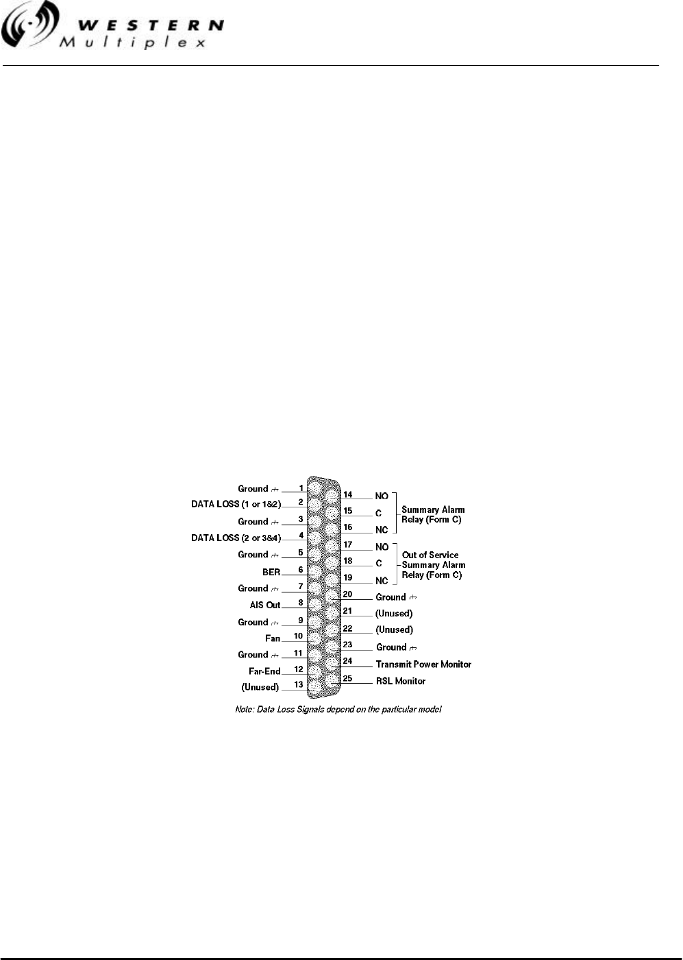
INSTALLATION AND MAINTENANCE MANUAL
LYNX.sc E1 FAMILY
SPREAD SPECTRUM RADIOS
SEPTEMBER 1999
PAGE 3-46 SECTION 3: INSTALLATION & ADJUSTMENTS
3.14.2 Alarm Connections
External alarm outputs are provided at the 25-pin, D-type subminiature ALARM connector. There are
two Form C summary alarm relays capable of switching 30 VDC at 1 A. Also, individual alarm logic
outputs capable of sourcing and sinking 1mA are provided. These individual alarms interface to a
single standard TTL load. When the unit is IN ALARM = “0”, the TTL output is 0 V to ±0.5 V. When
the unit is NO ALARM = “1”, the TTL output is +3.5 V to +5.5 V. See Table 3-E and Figure 3-21 for
Alarm Connections.
The “summary” alarm (Form C relay) is activated by any near-end front panel LED alarm condition,
including if the loopback mode is enabled.
The “out-of-service summary” alarm (Form C relay) is activated by any of the following alarm
conditions:
vRX SYNC
vRadio Fail
vLoopback Enabled
Figure 3-21: Pin Connections, ALARM Interface

INSTALLATION AND MAINTENANCE MANUAL
LYNX.sc E1 FAMILY
SPREAD SPECTRUM RADIOS
SEPTEMBER 1999
SECTION 3: INSTALLATION & ADJUSTMENTS PAGE 3-47
PIN 2 DATA LOSS (1 or 1&2) - in alarm if no
incoming data is received into the transmitter
for channel 1 (for the 4xE1 model, includes
channel 2). Data Loss is activated when the
input signal drops below 0.97 volts for 175 bit
intervals and is deactivated as soon as the
input signal level rises above 0.97 volts. Radio
transmits AIS to the far-end if in alarm. This
alarm may be disabled by DIP switch selection
(see Section 3.12.4).
PIN 16 NC, SUMMARY ALARM, FORM C - normally
closed connection on summary alarm relay.
PIN 4 DATA LOSS (2 or 3&4) – use essentially the
same description as Data Loss (1 or 1&2), for
channel 2 (for the 4xE1 model, channels 3&4).
PIN 17 NO, OUT OF SERVICE SUMMARY ALARM,
FORM C - normally open connection on out-of-
service summary alarm relay. Closed when in
alarm.
PIN 6 BER - in alarm when the received signal is
degraded to an error rate above radio threshold
(approximately 1 x 10⁻⁶)
PIN 18 C, OUT OF SERVICE SUMMARY ALARM,
FORM C - common connection for the out-of-
service summary alarm relay.
PIN 8 AIS OUT - in alarm when the BER exceeds 1 x
10-3 for the received signal, or when there is an
RX SYNC alarm condition. Near-end radio
CEPT-1 line output has AIS when in alarm. This
alarm may be disabled as described in Section
3.12.5.
PIN 19 NC, OUT OF SERVICE SUMMARY ALARM,
FORM C - normally closed connection on out-
of-service summary alarm relay. Open when in
alarm.
PIN 10 FAN - in alarm when one or both of the internal
fans are not operative.
PIN 21 NOT USED
PIN 12 FAR-END - in alarm when the far-end radio has
an alarm condition.
PIN 22 NOT USED
PIN 14 NO, SUMMARY ALARM, FORM C - normally
open connection on summary alarm relay.
Closed when in alarm.
PIN 24 TX PWR MON - voltage equal to the TX PWR
front panel voltage.
PIN 15 C, SUMMARY ALARM, FORM C - common
connection on the summary alarm relay.
PIN 25 RSL MON - voltage equal to the RSL front
panel voltage. Equals far-end RSL if DISPLAY
FAR END button is pressed and held.
PINS 1, 3, 5, 7, 9, 11, 20, & 23 GROUND, CHASSIS CONNECTION
Table 3-E: Alarm Interface Connections
All alarms are active for a minimum of one second, or as long
as the alarm condition persists, which ever is longer.
TTL signals are “in alarm” when there is a TTL zero condition
(0 V to ± 0.5 V).
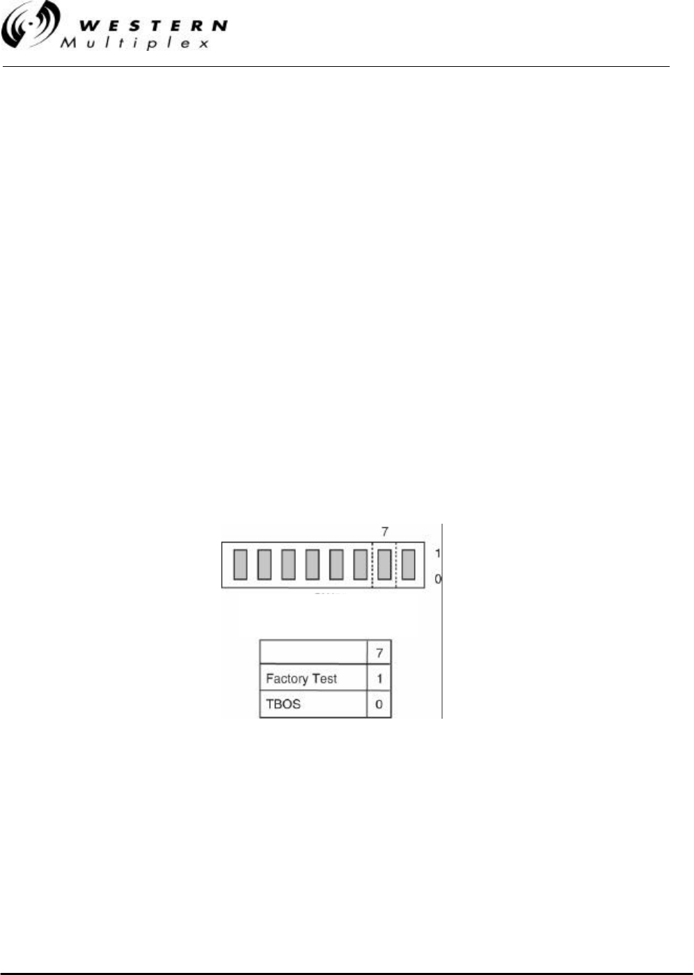
INSTALLATION AND MAINTENANCE MANUAL
LYNX.sc E1 FAMILY
SPREAD SPECTRUM RADIOS
SEPTEMBER 1999
PAGE 3-48 SECTION 3: INSTALLATION & ADJUSTMENTS
3.14.3 Diagnostics Port Operation
The Diagnostics Port is used to retrieve diagnostic or network management information about the
LYNX.sc radios by means of a computer connection. This can be accomplished locally or remotely.
Remote diagnostic port connections require either a modem (not included) connection be made to
the serial port, when a local dial-up phone line is available at a radio site, or by means of direct
connection through the AUX DATA port (Service Channel). The use of the AUX DATA channel can
provide a “network management” port where serial interface data is available from all LYNX.sc radios
in a network, provided that they are configured properly for this type of operation. (This section and
Section 3.14.4 describe this further).
The diagnostics port allows connection of either EIA standard RS-232 or RS-422 devices to poll and
receive status of the LYNX.sc radio. This serial port provides similar information to that which is
normally available to a local operator by means of visual alarms and status (front panel LEDs,
ADDRESS, DIP switch settings etc.), including voltage level measurements (such as RSL, PWR)
and alarm port (see Section 3.14.2) status. The diagnostics port can also provide extended
information including some advanced diagnostics and configuration information. Any information that
is available on the far-end terminal is also available at the near-end Diagnostics port (such as far-
end RSL, far-end alarms) by means of bridging the AUX DATA port (as described in Section 3.14.4).
A DIP switch is used to define the command protocol for this port as shown in Figure 3-22. The
default setting is for TBOS commands (as described later in this section). The other setting is for
factory use only.
Figure 3-22: Diagnostic Port Protocol Selection
SW1
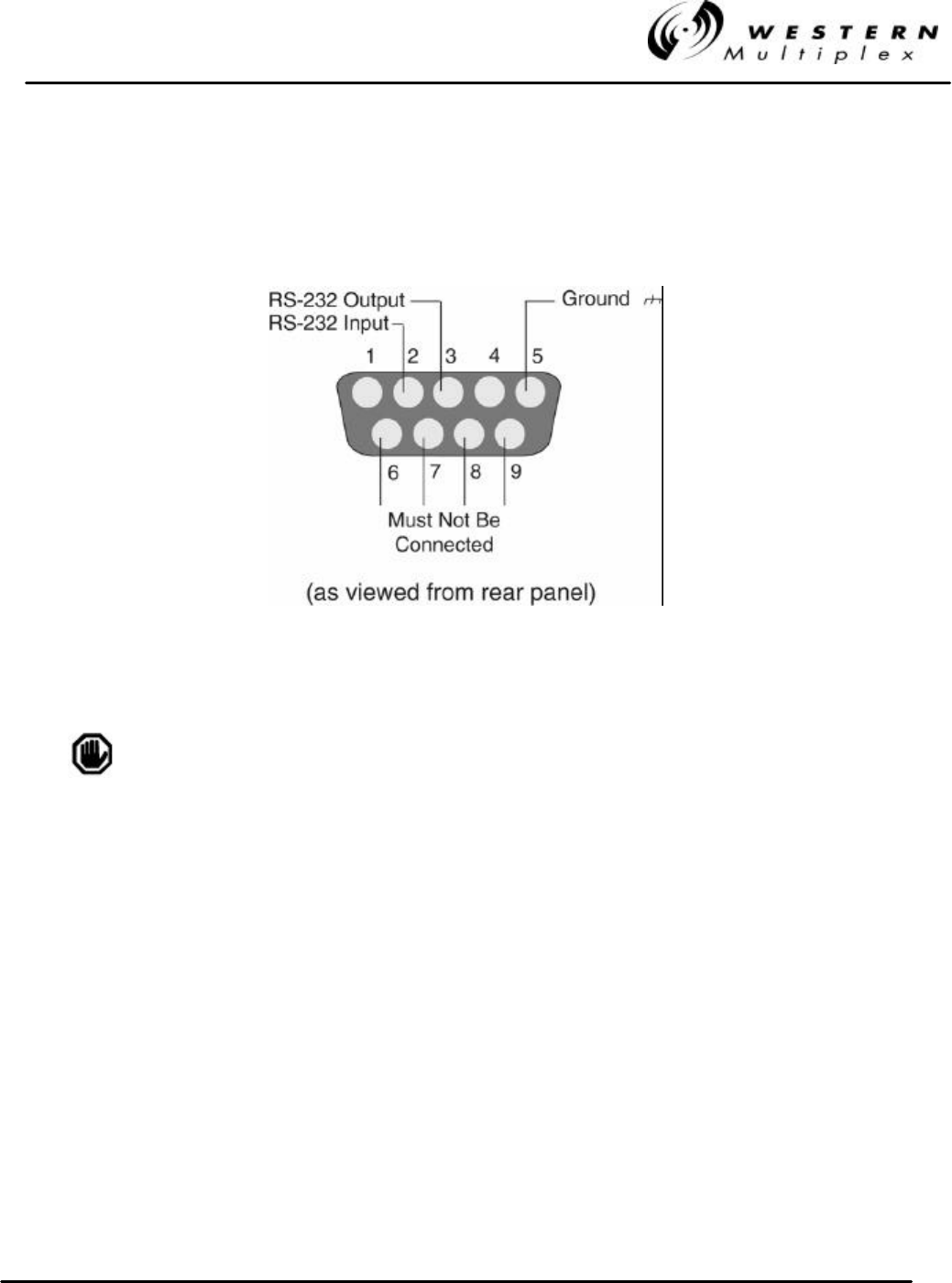
INSTALLATION AND MAINTENANCE MANUAL
LYNX.sc E1 FAMILY
SPREAD SPECTRUM RADIOS
SEPTEMBER 1999
SECTION 3: INSTALLATION & ADJUSTMENTS PAGE 3-49
3.14.3.1 Diagnostics Port using RS-232
For RS-232 diagnostics connection to the LYNX.sc radio, connect the serial device (modem,
computer, terminal) to the male 9-pin subminiature connector in accordance with Figure 3-23.
Figure 3-23: RS-232 Diagnostic Port Connections
Pins 6 through 9 must not be connected for RS-232
communications to operate properly.
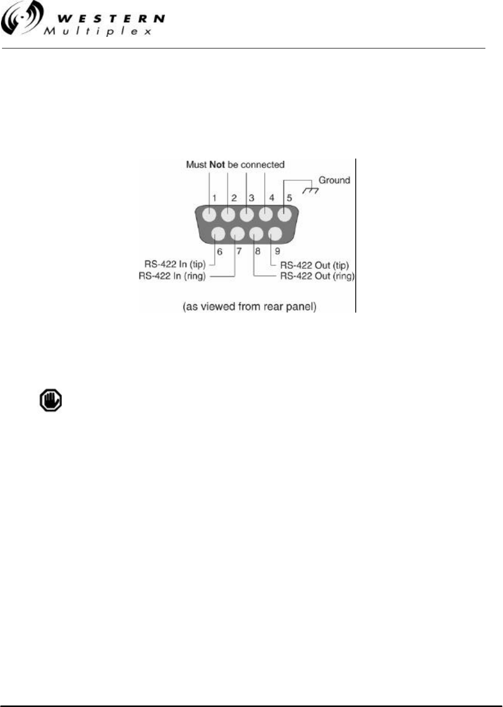
INSTALLATION AND MAINTENANCE MANUAL
LYNX.sc E1 FAMILY
SPREAD SPECTRUM RADIOS
SEPTEMBER 1999
PAGE 3-50 SECTION 3: INSTALLATION & ADJUSTMENTS
3.14.3.2 Diagnostics Port using RS-422
For RS-422 Diagnostics connection to the LYNX.sc radio, connect to the serial device (modem,
computer, terminal) to the male 9-pin subminiature connector in accordance with Figure 3-24.
Figure 3-24: RS-422 Diagnostic Port Connections
Do not connect devices to both the RS-232 and RS-422
connections of the Diagnostics Port. This will cause data
conflicts that will result in errors over the interface.

INSTALLATION AND MAINTENANCE MANUAL
LYNX.sc E1 FAMILY
SPREAD SPECTRUM RADIOS
SEPTEMBER 1999
SECTION 3: INSTALLATION & ADJUSTMENTS PAGE 3-51
3.14.3.3 TBOS Protocol and Map
The diagnostics port is configured for an open industry standard protocol, called Telemetry Byte
Oriented Serial (TBOS). TBOS is a poll and response protocol that operates on a RS-422 4-wire
interface, one pair for transmit data (requests) to the radio, and one pair for receive data (responses)
from the radio. TBOS is asynchronous, serial, half duplex transmissions of ASCII words which
consist of one start bit, 8 data bits, odd parity and two stop bits at 1200 baud. The connected
terminal (remote or local) can poll the radio and determine status of the connected LYNX.sc radio.
The LYNX.sc is also able to communicate TBOS commands over the RS-232 connections, instead
of the RS-422 connections if desired.
TBOS operates with a bit-map structure where each bit that the connected LYNX.sc radio sends to
the TBOS terminal has a specific meaning with regard to status, alarms or controls. All TBOS
network elements require a map for the network management software to interpret their responses
to queries from the terminal. Table 3-F provides the TBOS map for the E1 LYNX.sc radios.
The near-end RSL and Tx power test point voltages are encoded as 8 bit words that can be
converted into reference voltages (the same as at the front panel of the radio.
The address of the radio (see Section 3.14.1) serves as the “display” page number for the TBOS
data. Since TBOS is limited to eight (8) displays of data, it is required that addresses of 01 through
08 be used for LYNX.sc radios in TBOS networks. Any radio with addresses other than 01 through
08 will not report to the TBOS bit-map. In order to view status displays of far-end radios, or other
radios in the connected network, the AUX DATA port must be in Bridge (default) mode as described
in Section 3.14.4.
Alarm points within the TBOS map behave like the radio front and
rear panel alarms. If DIP switches have been set to disable
alarms, the alarms are disabled within the TBOS map.

INSTALLATION AND MAINTENANCE MANUAL
LYNX.sc E1 FAMILY
SPREAD SPECTRUM RADIOS
SEPTEMBER 1999
PAGE 3-52 SECTION 3: INSTALLATION & ADJUSTMENTS
Byte Point Bit Type*Scan Point Definition Control Point Definition Notes
1 7 SModel ID MSB 0011 = 2.4 GHz E1 (Model 31500)
2 6 SModel ID LSB+2 0100 = 5.8 GHz E1 (Model 31400)
3 5 SModel ID LSB+1 0101 = 5.8 GHz 2xE1 (Model 31700)
14 4 SModel ID LSB 1100 = 5.8 GHz 4xE1 (Model 31850)
5 3 N/A Future Use
6 2 SChannel Plan ID MSB SW3 pos 6 00=A, 01=B, 10=C
7 1 SChannel Plan ID LSB SW3 pos 7 Defaulted to 00 (A) for Model 31800
8 0 SChannel Plan Tx High/Low SW3 pos 8 (1 = Tx High, i.e. A2, B2, C2)
9 7 ARadio Fail Alarm Equal to F/P alarm
10 6 AAIS Out Alarm Equal to F/P alarm
11 5 AFan Alarm Equal to F/P alarm
212 4 ARx Sync Alarm Equal to F/P alarm
13 3 ALoopback Error Alarm Equal to F/P alarm
14 2 ABER Alarm Equal to F/P alarm
15 1 AFar-End Alarm Equal to F/P alarm
16 0 ATelemetry Down Alarm Equal to F/P alarm
17 7 AData Loss Ch1 Alarm Equal to F/P alarm
18 6 AData Loss Ch2 Alarm Equal to F/P alarm, where applicable
19 5 AData Loss Ch3 Alarm Equal to F/P alarm, where applicable
320 4 AData Loss Ch4 Alarm Equal to F/P alarm, where applicable
21 3 SData Loss Ch1 Alarm Disabled SW1 pos 1
22 2 SData Loss Ch2 Alarm Disabled SW1 pos 2, where applicable
23 1 SData Loss Ch3 Alarm Disabled SW3 pos 3, where applicable
24 0 SData Loss Ch4 Alarm Disabled SW3 pos 4, where applicable
25 7 SLoopback Test Source SW1 pos 3 (0 = Internal, 1 = External)
26 6 SLoopback Error LED Mode SW1 pos 4 (0 = Latched, 1 = Momentary)
27 5 S/C Loopback Channel 1 Enabled Loopback Channel 1 On/Off Front panel switch
428 4 S/C Loopback Channel 2 Enabled Loopback Channel 2 On/Off Front panel switch, where applicable
29 3 S/C Loopback Channel 3 Enabled Loopback Channel 3 On/Off Front panel switch, where applicable
30 2 S/C Loopback Channel 4 Enabled Loopback Channel 4 On/Off Front panel switch, where applicable
31 1 SAIS Disabled SW1 pos 5
32 0 SBridge Disabled (Aux Enabled) SW1 pos 8
33 7 N/A Future Use
34 6 N/A Future Use
35 5 N/A Future Use
536 4 N/A Future Use
37 3 SFar-End Address Invalid 1=Address>08
38 2 SFar-End Address MSB 000=01, 001=02, 010=03,
39 1 SFar-End Address LSB+1 011=04, 100=05, 101=06,
40 0 SFar-End Address LSB 110=07, 111=08
41 7 SNear-End RSL MSB RSLVOLTAGE ≈ Binary Byte(integer) x 0.04 Volts
42 6 SNear-End RSL MSB-1
43 5 SNear-End RSL MSB-2 Note The 8-bit binary value (0-255) represents
644 4 SNear-End RSL MSB-3 RSL values between -50 dBm and threshold.
45 3 SNear-End RSL MSB-4 Radio paths with higher RSL values will read
46 2 SNear-End RSL MSB-5 approximately five (5) to ten (10) VDC on the radio’s
47 1 SNear-End RSL MSB-6 front panel test point but be limited to a maximum
48 0 SNear-End RSL MSB-7 binary reading of 255 which represents 5 VDC.
49 7 SNear-End Tx Power MSB
50 6 SNear-End Tx Power MSB-1
51 5 SNear-End Tx Power MSB-2
752 4 SNear-End Tx Power MSB-3 8-bit byte derives voltage or dBm
53 3 SNear-End Tx Power MSB-4 TxPWRVOLTAGE ≈ Binary Byte(integer) x 0.02 Volts
54 2 SNear-End Tx Power MSB-5
55 1 SNear-End Tx Power MSB-6
56 0 SNear-End Tx Power MSB-7
57 7 SBoth Fans Bad Only applies if Point 11=1
58 6 STx Synth Unlock Only applies if Point 9=1
59 5 SRx Synth Unlock Only applies if Point 9=1
860 4 SInput Line Driver Only applies if Point 9=1
61 3 SDigital Hardware Only applies if Point 9=1
62 2 N/A Future Use Key: A = Alarm
63 1 N/A Future Use S = Status
64 0 N/A Future Use C = Control
Table 3-F: TBOS Map for the LYNX.sc E1s

INSTALLATION AND MAINTENANCE MANUAL
LYNX.sc E1 FAMILY
SPREAD SPECTRUM RADIOS
SEPTEMBER 1999
SECTION 3: INSTALLATION & ADJUSTMENTS PAGE 3-53
3.14.4 AUX DATA (Digital Service Channel) Connection
The AUX DATA port is a separate wayside serial port which can be configured to allow the
connection of any user serial data (to 9600 baud) through the radio network. In the default
configuration, this service channel is “bridged” to the diagnostics port, providing TBOS network
management for far-end radios including radio network management through repeaters and hubs.
Connection to the AUX DATA port is an RS-232 or RS-422 serial interface, identical to the
diagnostics port (see Section 3.14.3). This port does not affect the E1 traffic on the LYNX.sc radio.
For TBOS network management, or when the AUX DATA port is used as a clear service channel,
co-located radios can be wired to one another to provide the information throughout the network. At
a repeater or hub location, bridging is accomplished by cable connections between co-located
LYNX.sc radios, via their AUX DATA ports, as shown in Figure 3-25 and 3-26. Figure 3-27 illustrates
the pin-to-pin connections for this configuration. There is a related DIP switch position, as shown in
Figure 3-27, that makes the AUX DATA port usable for customer data instead of the TBOS network
management information. The factory default setting for this DIP switch is for TBOS network
management.
For non-TBOS external site management systems can be used with the LYNX.sc radios; Figure 3-
26 shows a typical application. Here the reporting relies on external devices to communicate over
the clear service channel of the LYNX.sc radio. Each radio is given a site location (see Section
3.14.1) and information on the radio status and control is fed through the diagnostic port to a remote
terminal unit (RTU). These RTUs have the capability of providing for other external inputs at the
remote site, for complete network management. Communication from each RTU is fed via the RS-
232 port to the AUX DATA connector on the radio, in this configuration no bridging is required.
RTUs that do not support TBOS can alternatively connect to the
LYNX.sc alarm connector for discreet TTL alarms and/or test
point voltages.
If you are using TBOS network management and want full
information on the far-end radio (even in a single-hop
application), the bridge function must be enabled.
The service channel can only be used for TBOS network
management or for Aux data, not both. When selected for
TBOS, no other data should be connected to the AUX DATA
port.
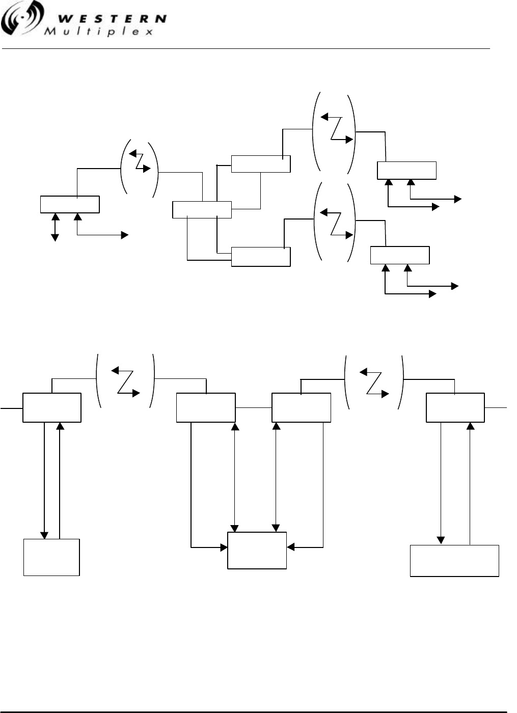
INSTALLATION AND MAINTENANCE MANUAL
LYNX.sc E1 FAMILY
SPREAD SPECTRUM RADIOS
SEPTEMBER 1999
PAGE 3-54 SECTION 3: INSTALLATION & ADJUSTMENTS
Figure 3-25: Repeater and Hub TBOS Radio Network Management
Figure 3-26: Repeater Application with Site Network Management
Antenna
Diagnostics
Diagnostics
2 X T1
LYNX.sc
Antenna
T1
Diagnostics
T1
Aux. DATA
Aux. DATA
LYNX.sc
LYNX.sc
LYNX.sc
Antenna
Antenna
Antenna
Diagnostics
LYNX.sc
Antenna
Diagnostics
LYNX.sc
T1
T1
RS-232
T1
RS-232
T1
LYNX.sc
Diag. AUX.
01
Site
Address
TBOS
Info at
this
radio
03
Site
Address
TBOS
Info at
this
radio
LYNX.sc
Diag. AUX.
LYNX.sc
AUX Diag
Remote
Terminal
Unit
02
Site
Address
TBOS
Info at
this
radio
RS-232
04
Site
Address
TBOS
Info at
this
radio
T1
LYNX.sc
Diag. AUX.
Network
Manager Remote
Terminal Unit
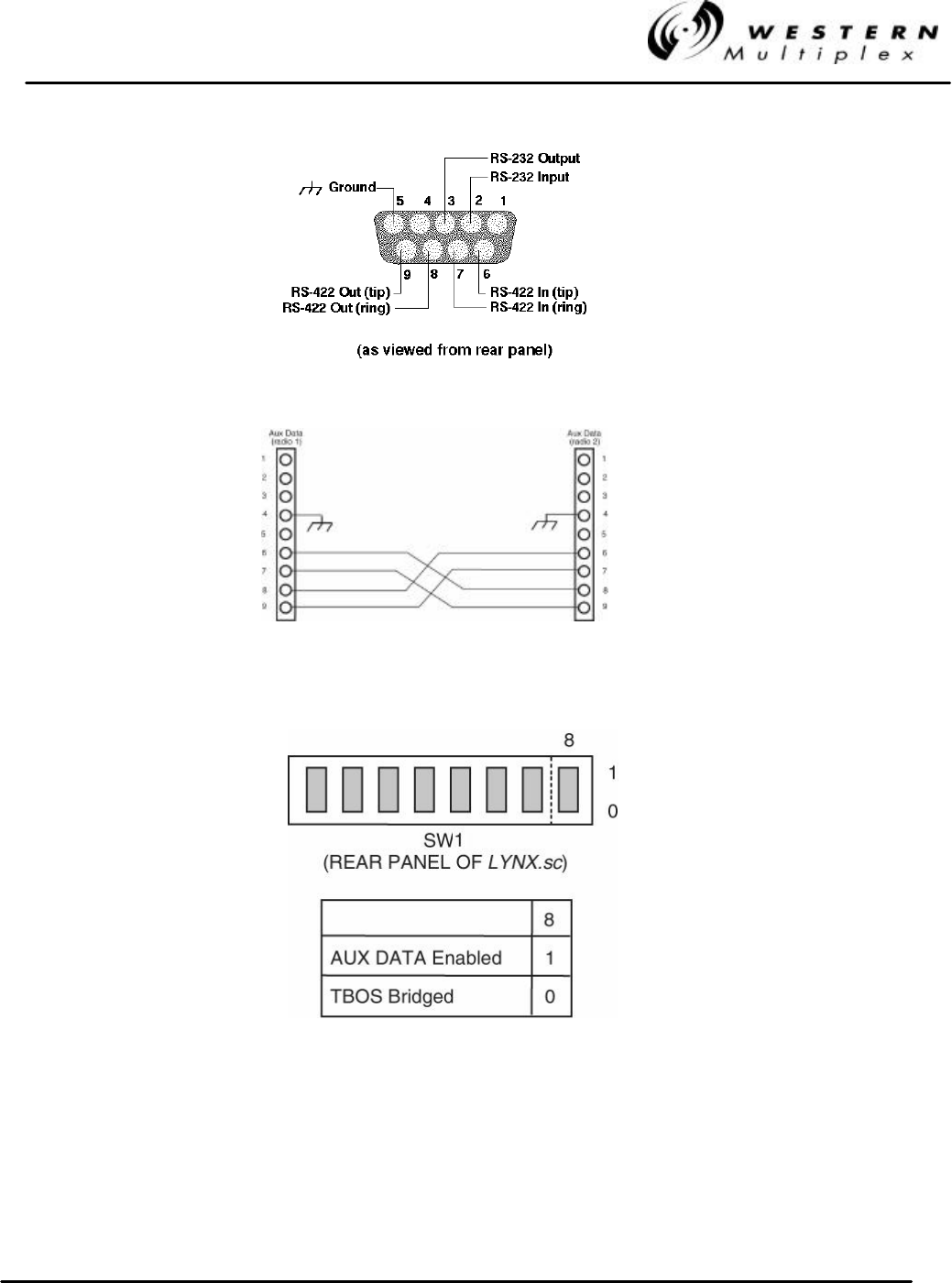
INSTALLATION AND MAINTENANCE MANUAL
LYNX.sc E1 FAMILY
SPREAD SPECTRUM RADIOS
SEPTEMBER 1999
SECTION 3: INSTALLATION & ADJUSTMENTS PAGE 3-55
Figure 3-27: AUX DATA Cable Connection for Repeater/Hub
Figure 3-28: AUX Data Selection
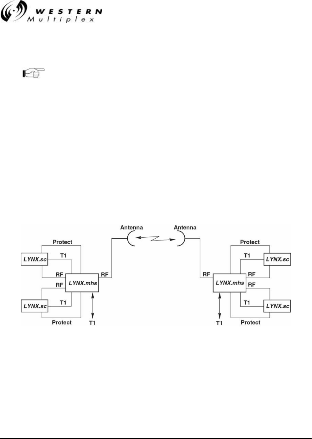
INSTALLATION AND MAINTENANCE MANUAL
LYNX.sc E1 FAMILY
SPREAD SPECTRUM RADIOS
SEPTEMBER 1999
PAGE 3-56 SECTION 3: INSTALLATION & ADJUSTMENTS
3.14.5 Protect Port Connection (Preliminary Information)
This feature is not yet available as of the publishing date of
this manual.
The protect port is an 8-pin modular jack connection which is used in conjunction with an auxiliary
piece of equipment called a LYNX.SC.mhs. The LYNX.sc protection port implements control
information for the purposes of Monitored Hot Standby (MHS) or Space Diversity (SD) radio
configurations. Purchase of the LYNX.SC.mhs equipment is required to implement this feature of
the LYNX.sc radio. Details of the specific connection requirements to this equipment are supplied in
the LYNX.SC.mhs manual.
MHS is a configuration of equipment which essentially supports a “back-up” radio, in case of radio
hardware failure. For the LYNX.sc this is accomplished by connecting the antenna and E1
connections to the LYNX.SC.mhs unit, and then connecting the LYNX.SC.mhs unit to two separate
and identical LYNX.sc radios. The LYNX.SC.mhs unit provides the capability to switch between
connected LYNX.sc radios in case of a radio hardware failure. There is an interruption in radio traffic
when this switching occurs, however, radios are typically able to resynchronize and establish
communications in a few seconds (depending on path length and path availability). A typical MHS
configuration is shown in Figure 3-29.
Figure 3-29: MHS Configuration
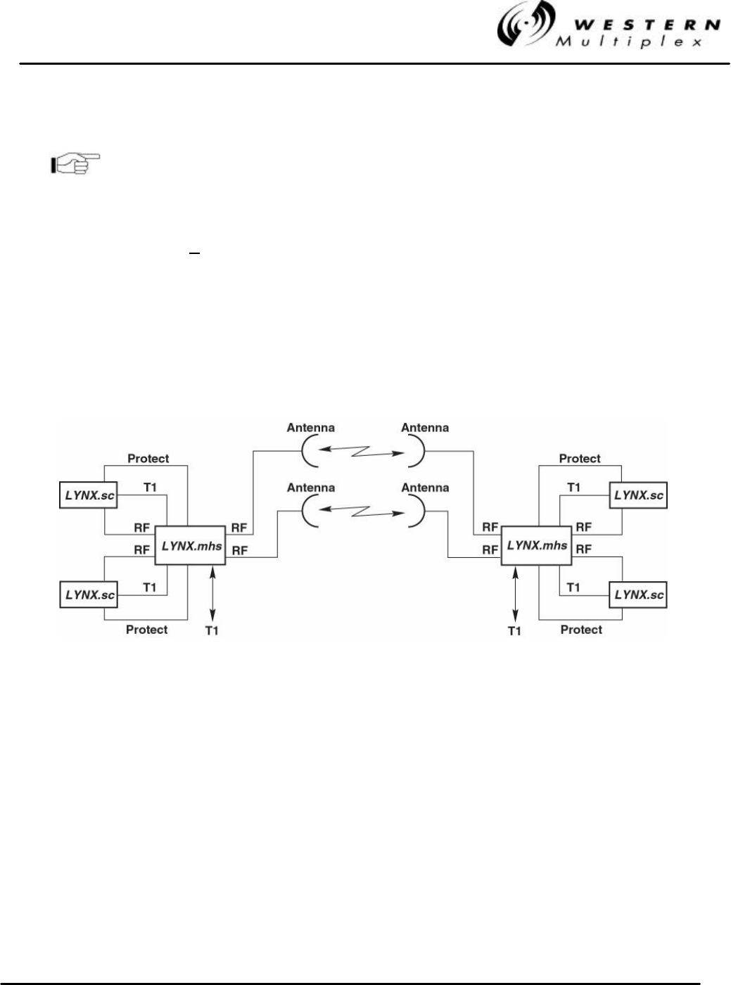
INSTALLATION AND MAINTENANCE MANUAL
LYNX.sc E1 FAMILY
SPREAD SPECTRUM RADIOS
SEPTEMBER 1999
SECTION 3: INSTALLATION & ADJUSTMENTS PAGE 3-57
3.14.6 Protect Port Connection (Preliminary Information)
This feature is not yet available as of the publishing date of
this manual.
Space Diversity (SD) is a similar application for radios where there is a “back-up” path for the radio
in case of radio failure or path outage problems. This type of application is typically configured as
two separate radios at the same site connected to two separate antennas. The separate antennas
yield a slightly different path and therefore may provide better performance in cases of path outage
due to weather or interference. There is an availability improvement due to multipath fading in a SD
configuration as compared to a non-protected system configuration. A representative SD
configuration is shown in Figure 3-30.
Figure 3-30: SD Configuration

INSTALLATION AND MAINTENANCE MANUAL
LYNX.sc E1 FAMILY
SPREAD SPECTRUM RADIOS
SEPTEMBER 1999
PAGE 3-58 SECTION 3: INSTALLATION & ADJUSTMENTS
Your Notes on the LYNX.sc Radio

INSTALLATION AND MAINTENANCE MANUAL
LYNX.sc E1 FAMILY
SPREAD SPECTRUM RADIOS
SEPTEMBER 1999
SECTION 4: TROUBLESHOOTING PAGE 4-1
4. Troubleshooting
4.1 Regular Maintenance
The LYNX.sc radios do not require any regular maintenance, however, it is prudent to monitor the
radio link at regular intervals to assure that the link conditions are not changing. When visiting a
radio site for maintenance, the following items may be checked and their results recorded:
vRSL Voltage
vPWR Voltage
vFar-end RSL Voltage
vAlarm conditions
vVerify radio has adequate ventilation
If any alarm conditions exist, they should be recorded, and troubleshooting procedures from this
Section of the manual should be followed.

INSTALLATION AND MAINTENANCE MANUAL
LYNX.sc E1 FAMILY
SPREAD SPECTRUM RADIOS
SEPTEMBER 1999
PAGE 4-2 SECTION 4: TROUBLESHOOTING
4.2 Changing Frequency Plans
The LYNX.sc RF frequency selections are listed in Section 3.5. The near-end radio and the far-end
radio must be corresponding (e.g. A1 / A2). The frequency of a given LYNX.sc terminal is set by the
specific filter, the physical orientation of this assembly, and the setting of corresponding DIP
Switches. (See Section 3.12.1 for more details.)
With respect to a given filter, the frequencies are fixed, because tuned RF filters are required for
normal operation. Changing of the (pretuned) radio frequencies may be required when installing
spares or for special situations, such as interference mitigation. This is accomplished by installing
an alternate filter or reorienting the existing filter.
For any given model of LYNX.sc (2.4 GHz 1xE1, 2.4 GHz 2xE1, 5.8 GHz 1xE1, 5.8 GHz 2xE1, or
5.8 GHz 4xE1), the frequency channel can be changed by swapping and /or reorienting the filter.
It is not necessary to remove the cover assembly of the LYNX.sc
1. Remove any cables connected to the antenna connector on the diplexer (filter) and
then remove the two screws which mount the filter to the LYNX.sc chassis.
2. Slowly remove the filter from the chassis being careful to not endanger the cables that are
connected to the rear side of the filter.
3. Disconnect the two SMA connectors that are attached to the rear of the filter with a 5/16”
open end wrench.
4. Select the new filter or orient the existing filter such that the frequency channel label on the
filter (showing the DIP switch positions) is right-side-up corresponding to the desired
frequency channel.
5. Connect the two SMA connectors to the new or reoriented filter with the 5/16” open end
wrench.
6. Slowly place the wired filter assembly so that it is flush with the rear panel.
7. Install the two screws which mount the filter to the rear panel.
8. Refer to the rear panel filter label or Section 3.12.1 for DIP Switch settings to correspond to
the new filter and reattach the antenna cable.
As an example, the filter assemblies of an A1 and A2 terminal are
identical. They are simply installed differently. An A1 terminal can
be changed into an A2 by removing the filter and rotating it 180
degrees and reinstalling the filter. The DIP switch positions need
to match the filter orientation, per the appropriate filter label.

INSTALLATION AND MAINTENANCE MANUAL
LYNX.sc E1 FAMILY
SPREAD SPECTRUM RADIOS
SEPTEMBER 1999
SECTION 4: TROUBLESHOOTING PAGE 4-3
4.3 Using a Spare Terminal
One spare LYNX.sc terminal of a given model type (2.4 GHz 1xE1, 2.4 GHz 2xE1, 5.8 GHz 1xE1,
5.8 GHz 2xE1, or 5.8 GHz 4xE1) will service any other radio in that same model type, independent
of frequency channel plan. For example, a 5.8 GHz E1 channel A2 can be used as a spare for any
A, B or C channel E1 radio at 5.8 GHz. See Section 4.2 for changing frequencies of a spare radio.
Customers with several radios, or radios in critical operations are encouraged to purchase one or
more spare radios of each model in their system. This will allow rapid restoration of radio service in
the unlikely event of a radio failure.

INSTALLATION AND MAINTENANCE MANUAL
LYNX.sc E1 FAMILY
SPREAD SPECTRUM RADIOS
SEPTEMBER 1999
PAGE 4-4 SECTION 4: TROUBLESHOOTING
4.4 Technical Support
Western Multiplex provides 24-hour telephone technical support for installed LYNX.sc radios.
Customers are encouraged to troubleshoot the radio and link in accordance with the latter part of
this section in this manual before contacting Western Multiplex. Western Multiplex also has a
limited supply of LYNX.sc radios that can be loaned to out-of-service customers for installation
while units are being repaired. Loaner supply is limited, and is only used for critical applications on
a first-come, first-served basis.
Customer service #: +1 408 542-5390

INSTALLATION AND MAINTENANCE MANUAL
LYNX.sc E1 FAMILY
SPREAD SPECTRUM RADIOS
SEPTEMBER 1999
SECTION 4: TROUBLESHOOTING PAGE 4-5
4.5 Repair Policy
The LYNX.sc terminal includes comprehensive alarm indicators designed to diagnose potential
faults. Should a fault occur, it often may be resolved by operator adjustment.
Should a fault occur that cannot be resolved by operator adjustment and has been confirmed by
looping terminals together on the bench (See Section 4.9), then the equipment should be returned
to the factory for repair.
The LYNX.sc radio is a complex system not designed for user repair. Do not remove the cover or
open any part of the LYNX.sc terminal. The complete LYNX.sc terminal should be sent back in its
original packing material for factory repair.
Please contact the factory in advance of returning the product. You will be assigned a Return
Material Authorization (RMA) number that authorizes your return. Units sent to the factory without
an RMA number may be delayed in the processing of the repair. Be sure to include the following
information:
vRMA number
vdescription of the problem
vyour name and telephone number
vreturn shipping address
vurgency of repair
Please refer to the published Warranty policy for repair policy
details.
LYNX.sc radios should be packaged in their original packing
boxes for shipment whenever possible Western Multiplex can
provide an empty box shipment to facilitate proper packaging.
Regardless, proper and adequate packaging must be used for
shipments to protect the radio(s) from damage. Western
Multiplex can not be held responsible for any repairs due to
inadequately packed materials. Damage caused by improper
packing will likely result in higher repair costs and delays (refer
to the Warranty section at the beginning of this manual).

INSTALLATION AND MAINTENANCE MANUAL
LYNX.sc E1 FAMILY
SPREAD SPECTRUM RADIOS
SEPTEMBER 1999
PAGE 4-6 SECTION 4: TROUBLESHOOTING
4.6 Front Panel Status LEDs
There are several front panel status LEDs on the LYNX.sc radio. These LEDs indicate conditions
where either a hardware failure has occurred or the radio link is not optimum. In many cases, a
combination of LEDs may be illuminated. The following sections describe the necessary
troubleshooting procedures should any LED(s) indicate a problem during or after installation.

INSTALLATION AND MAINTENANCE MANUAL
LYNX.sc E1 FAMILY
SPREAD SPECTRUM RADIOS
SEPTEMBER 1999
SECTION 4: TROUBLESHOOTING PAGE 4-7
4.6.1 DATA LOSS Alarms
Function:
These DATA LOSS Alarms indicate that no CEPT-1 signal is present at the rear panel CEPT-1
interface. On a multiple-capacity radio, the DATA LOSS 1 alarm relates to the DATA 1 ports while
the DATA LOSS 2 alarm relates to the DATA 2 ports. On the 4xE1 model, DATA LOSS 1&2 are
combined and DATA LOSS 3&4 are combined. This alarm does not indicate a radio hardware
failure.
The capacity of the radio will determine how many DATA LOSS
LEDs there are on the front panel.
Sometimes a double-capacity radio is put into service with only
one input channel active, with the second channel planned for
future growth. In this case, the DATA LOSS 2 alarm will be
active because no CEPT-1 signal will be present. This alarm can
be defeated by selecting a rear panel DIP switch as described in
Section 3.12.4.
When there is a data loss condition, even if the data loss alarm
has been disabled, the LYNX.sc radio injects AIS into the (RF)
transmitted CEPT-1 signal.
Possible Causes:
vNo CEPT-1 connection present at rear panel
vImproper pin connections of CEPT-1 connector
vNo data on CEPT-1 input connector

INSTALLATION AND MAINTENANCE MANUAL
LYNX.sc E1 FAMILY
SPREAD SPECTRUM RADIOS
SEPTEMBER 1999
PAGE 4-8 SECTION 4: TROUBLESHOOTING
Recommended Actions:
1. Check to make sure that there is a CEPT-1 connection present on either of the connectors
(BNC) for the channel in alarm.
On a multiple-capacity radio, if the alarm is on a channel which is
unused at this time, the alarm condition can be disabled by a rear
panel DIP switch, as described in Section 3.12.4.
4. Verify that the CEPT-1 line has data active at the radio connection. This can be
accomplished using a BER tester or signal analyzer. Also, signal activity can be verified by
using an oscilloscope.
5. Verify that pin connections have been made properly (in accordance to Section 3.11). Make
sure that you have connected the CEPT-1 with respect to the transmitting device.
6. Connect a BER tester or signal analyzer to the CEPT-1 Monitor INPUT port on the rear
panel.

INSTALLATION AND MAINTENANCE MANUAL
LYNX.sc E1 FAMILY
SPREAD SPECTRUM RADIOS
SEPTEMBER 1999
SECTION 4: TROUBLESHOOTING PAGE 4-9
4.6.2 BER (Bit Error Rate) Alarm
Function:
This LED indicates that the traffic being received from the far-end radio is exceeding the bit error
rate threshold of the radio (approximately 1 x 10⁻⁶). This indicates that radio traffic currently has
errors on it which may exceed acceptable levels. This LED will stay ON as long as the BER
threshold is being exceeded. In some cases, it will turn ON and OFF, in which case there are
bursts of errors causing intermittent degradation to the received data. In all cases, the LED will be
on for at least 1 second for any group of errors which exceed the threshold, whether they are a burst
of errors or a long string of errors.
If the RX SYNC alarm is on the near-end or far-end radio in
addition to the BER alarm (on the same radio), the RX SYNC
alarm should be the first priority for troubleshooting.
Possible Causes:
vPath fading due to atmospheric conditions (usually accompanied by Far-End BER alarm)
and low RSL voltage reading
vPoor transmission line connections (usually accompanied by Far-End BER alarm) and
low RSL voltage reading
vAntenna problems, misalignment or path clearance (usually accompanied by Far-End
BER alarm) and low RSL voltage reading
vInterference
vReceived signal level (RSL) is too strong
vFar-end radio transmitter circuitry is faulty or Tx Power adjusted incorrectly (too low)
vNear-end radio receiver circuitry is faulty

INSTALLATION AND MAINTENANCE MANUAL
LYNX.sc E1 FAMILY
SPREAD SPECTRUM RADIOS
SEPTEMBER 1999
PAGE 4-10 SECTION 4: TROUBLESHOOTING
Recommended Actions:
An internal loopback test should be performed to verify that errors are occurring over the link:
vVerify that the near-end radio is set for Internal test mode and Latched Error LED (both
default settings of rear panel DIP switch positions, as described in Sections 3.12.2 and
3.13.3).
vPress and hold (for approximately 3 seconds, then release) the Loopback Enable switch
on the front panel of one radio (this will take radios out of service). Let this test run for a
few minutes.
vIf the ERROR LED illuminates, this is verification that errors are on the link and
troubleshooting should continue.
vPress the Loopback Enable switch to deactivate loopback mode.
Next measure RSL by placing a voltmeter across RSL and GND test points. Compare this voltage
to the Factory Test Data Sheet and estimate the RSL in dBm. Compare this to the RSL that was
expected using path calculations (see Section 3.3.3). Press and hold the DISPLAY FAR END
button and measure the far-end RSL (while continuing to hold the button). Compare this RSL to the
Factory Test Data Sheet for the far-end radio and estimate the RSL in dBm. Again, compare this
RSL to the expected RSL from the link budget calculations.
If RSL from both ends of the radio are approximately the same as each other, but lower than
anticipated for this installation, then the likely cause of the BER alarm(s) is excessive losses
between the radios. Excessive loss problems could include the transmission line at either end, all
adapters, connectors, the antennas, the antenna alignment as well as the path itself (any
obstructions or clearance problems). Antenna alignment, line-of-sight and path clearance should be
verified; if this does not improve RSL, all devices between the radios and their antennas at both
ends should be checked. Make sure all transmission line, connectors and any other devices are
properly rated for operation at the radio's frequency (2.4 or 5.8 GHz).
If only one end has low RSL, this could be caused by low transmit output power from the opposite
end radio. Verify that the transmitter output power of the radio opposite to the low RSL receiver has
been set in accordance to path calculations, or EIRP restrictions (where applicable). Power
adjustment must be performed by professional installation personnel only. The PWR test point can
be used and compared with the Factory Test Data Sheet, the front panel recessed potentiometer
can be turned clockwise to increase power. If an RF power meter is available, this can be
connected to the RF output of the radio for precision measurement. This test will also verify that the
radio transmitter is working properly.

INSTALLATION AND MAINTENANCE MANUAL
LYNX.sc E1 FAMILY
SPREAD SPECTRUM RADIOS
SEPTEMBER 1999
SECTION 4: TROUBLESHOOTING PAGE 4-11
If one terminal (or both) has high RSL, this could be caused by a very short path or interference. To
verify the possible presence of interference, remove DC power to the radio which is opposite to the
one that is reading high RSL. Once power is removed, measure RSL on the remaining radio. If RSL
voltage is higher than that which is listed for "Threshold" in the Factory Test Data Sheet, then an
interfering signal is present. If interference is suspected, the easiest potential remedy is to swap
frequency channels on both sides of the link. See Section 4.2 for details. Swap frequencies on both
terminals so that they are the opposite from their original settings (e.g. change A1 into A2 and A2
into A1). Make sure that you change the DIP switch settings to correspond to the channel change.
After both ends are changed, reconnect the radios and determine if the BER alarm is still active. If
the BER alarm is still active, other frequency channels can be installed, or other interference
countermeasures can be tried, in accordance with Section 4.8.
If the BER alarm continues, an external BER test should be performed to verify the extent of bit
errors on the link. See Sections 4.9 and 4.10 for details on bit error rate testing. A BERT can be
connected on one side of the link, the External test mode selected on the near-end radio, loopback
enabled and bit errors evaluated. If the BER is above acceptable levels, continue to troubleshoot the
link.
If all path related and data input problems have been pursued and the BER alarm is still active, the
problem could be related to a radio failure. While radio failure is typically indicated by more severe
alarm conditions, it is possible that one of the radios may be out of specification, and this could be
the cause of the BER alarm. A back-to-back test will verify proper radio operation. See Section 4.9
for details. A threshold test on both radios along with a test to verify proper RF output power would
be beneficial.
Perform a back-to-back test before returning any radio terminal to
the factory for repair. A back-to-back test verifies radio operation.
(See Section 4.9).
If the radios successfully pass their back-to-back testing, the problem is likely with the path or the
connections between the radio and the antenna or interference. Before reinstalling the radios, be
sure to set the output power to the appropriate level for the installation and set rear panel DIP
switches to the desired settings for the installation.

INSTALLATION AND MAINTENANCE MANUAL
LYNX.sc E1 FAMILY
SPREAD SPECTRUM RADIOS
SEPTEMBER 1999
PAGE 4-12 SECTION 4: TROUBLESHOOTING
4.6.3 RX SYNC (Receiver Synchronization) Alarm
Function:
This LED indicates that the demodulator function is not synchronizing with the intended received
signal.
When the RX SYNC alarm is active, the LYNX.sc radio injects AIS onto the received CEPT-1 (line
transmit out), even if AIS has been disabled by rear panel DIP switch setting.
Possible Causes:
vSevere path fading due to atmospheric conditions (usually accompanied by Far-End RX
SYNC or BER alarm) and low RSL voltage reading
vPoor transmission line connections (usually accompanied by Far-End RX SYNC or BER
alarm) and low RSL voltage reading
vAntenna problems, misalignment, or path clearance (usually accompanied by Far-End RX
SYNC or BER alarm) and low RSL voltage reading
vImproper radio settings (frequency channel, spread code)
vInterference
vFar-End radio transmitter circuitry is faulty
vNear-End radio receiver circuitry is faulty
Recommended Actions:
Check the following at each end of the link:
vVerify that rear panel filters are opposite channel plans on each end (e.g. one is A1 and
other is A2).
vVerify that rear panel DIP switch settings match each installed filter (see Section 3.12.1).
vVerify that each radio is set to the same spreading code (see Section 3.12.3).
vVerify that all connections between radios and antennas are secure and all devices
between radios and antennas are rated for the radio frequency band (2.4 or 5.8 GHz).
If RX SYNC alarm continues, follow recommended actions for a BER alarm as described in Section
4.6.2.

INSTALLATION AND MAINTENANCE MANUAL
LYNX.sc E1 FAMILY
SPREAD SPECTRUM RADIOS
SEPTEMBER 1999
SECTION 4: TROUBLESHOOTING PAGE 4-13
4.6.4 AIS OUT (Alarm Indication Signal)
Function:
This LED informs the user that the near-end receiver is operating at BER ≥ 1 x 10⁻³ or is not
receiving data and is therefore injecting AIS to the line transmit out of the CEPT-1 connector.
If the AIS has been disabled by rear panel DIP switch, AIS will not be injected onto the line transmit
output unless there is a loss of sync (RX SYNC alarm).
Possible Causes:
vLocal receiver has lost lock (RX SYNC)
vLocal receiver is operating at BER >1 x 10⁻³
Recommended Actions:
1. Follow recommended actions for a RX SYNC alarm, as described in Section 4.6.3.

INSTALLATION AND MAINTENANCE MANUAL
LYNX.sc E1 FAMILY
SPREAD SPECTRUM RADIOS
SEPTEMBER 1999
PAGE 4-14 SECTION 4: TROUBLESHOOTING
4.6.5 FAN Alarm
Function:
This alarm activates only when one or both of the internal fans are faulty.
Possible Cause:
vFaulty fan inside the radio.
Recommended Actions:
1. Check environmental conditions of the radio. Assure that the ambient temperature at the radio
location is within specification of the radio. If not, apply environmental conditioning to radio
location or place radio at alternate location where the environmental specifications are met.
2. Visually inspect radio mounting area and ensure that right and left sides of the radio chassis
are unobstructed for airflow.
3. Verify that at least one of the internal fans are operational by temporarily covering some of the
ventilation holes on the right side of the radio (as you face the front panel) with a thin piece of
paper. Slowly pull the paper outwards away from the ventilation holes to determine if the fan is
pulling the paper toward the chassis. This can also be checked on the opposite side of the
chassis to verify that the fans are pushing air out of the chassis.
4. If at least one fan is working you may wish to postpone repair, as long as the unit is operating
without any other errors (the radio is designed to operate with only one fan)
5. If neither fan is working or if typical operating environment is greater than 30°C, it is
recommended that the unit be repaired at the soonest opportunity. Return the radio to the
factory for repair. See Section 4.5 for details.

INSTALLATION AND MAINTENANCE MANUAL
LYNX.sc E1 FAMILY
SPREAD SPECTRUM RADIOS
SEPTEMBER 1999
SECTION 4: TROUBLESHOOTING PAGE 4-15
4.6.6 RADIO FAIL Alarm
Function:
The RADIO FAIL alarm indicates a known problem with the radio hardware.
Possible Causes:
vInternal synthesizers are unlocked
vInternal digital circuits have failed
vCEPT-1 connection is incorrect
Recommended Actions:
1. Disconnect the CEPT-1 connections from the rear panel.
2. If RADIO FAIL alarm clears, check CEPT-1 connections for proper pin connections and
impedance as described in Section 3.11.
3. If RADIO FAIL alarm does not clear, remove power from the unit.
4. Check to make sure power supply voltages are within specification.
5. Even if the voltages were within specification, reapply power to the unit.
6. If RADIO FAIL alarm clears, place the radio back into service.
7. If RADIO FAIL alarm does not clear, perform a back-to-back test to verify radio operation, as
described in Section 4.9.
8. If RADIO FAIL alarm is still active in a back-to-back test, return the radio to the factory for repair
(see Section 4.5).

INSTALLATION AND MAINTENANCE MANUAL
LYNX.sc E1 FAMILY
SPREAD SPECTRUM RADIOS
SEPTEMBER 1999
PAGE 4-16 SECTION 4: TROUBLESHOOTING
4.6.7 FAR END Alarm
Function:
This LED indicates that there is an alarm condition present on the far-end radio. When the
DISPLAY FAR END button is pressed (and held), the status LEDs indicate the alarm conditions of
the far-end radio.
Possible Cause:
vOne or more alarm condition(s) exist on the far-end radio
Recommended Actions:
1. Press and hold the DISPLAY FAR END button and observe the LED status.
2. Follow instructions for troubleshooting the far-end radio in accordance to the appropriate LEDs
which are in alarm, as described in Section 4.6.1 through 4.6.6.

INSTALLATION AND MAINTENANCE MANUAL
LYNX.sc E1 FAMILY
SPREAD SPECTRUM RADIOS
SEPTEMBER 1999
SECTION 4: TROUBLESHOOTING PAGE 4-17
4.7 Errors in the Data Stream
When the radio is in service, errors in the data stream may occur. This is usually known to the
operator by either faulty data indications of downstream equipment, external bit error rate testing, or
ERROR LED indications during internal loopback testing.
During internal test mode loopback testing, if an error is detected, the ERROR LED will illuminate.
In default mode, this lamp will stay lit during loopback testing if a single error is detected. If
Loopback has been performed over a period of time and the ERROR LED does not latch on, the
radio link is operating completely error-free.
The ERROR LED only operates in internal test signal loopback
mode. Use a BERT to detect errors when using an external test
signal. See Sections 3.12.2, 3.13.2 and 3.13.3 for more details.
It is possible that no alarms appear on the front panel during normal operations, but there are errors
present in the data stream. If the BER LED is lit, this indicates rather severe error conditions and it
is best to follow the procedures provided in Section 4.6.1. However, some errors will not result in the
BER alarm (such as bipolar violations, slow "dribbling" errors, improperly terminated CEPT-1
connections or incorrect settings of switches), but will be exhibited on downstream data processing
equipment or during a BER test. In other cases, there may be data errors due to atmospheric
conditions (fading), interference or other reasons, but not at a high enough error level to be indicated
with the BER alarm LED. In the case of these types of errors, the following information can be
helpful to troubleshoot the radio link.
Indications:
vIn Loopback Mode, ERROR LED is illuminated
vDuring external BER test, test equipment indicates errors
vDownstream equipment (mux, channel bank, CODEC, router, etc.) indicates errors
Possible Causes:
vPath fading due to atmospheric conditions
vPoor transmission line connections
vAntenna problems, misalignment or path clearance
vReceived signal level (RSL) is too strong
vFar-End radio transmitter circuitry is faulty
vNear-End radio receiver circuitry is faulty
vInterference
Recommended Actions:
1. Verify CEPT-1 wiring in accordance to Section 3.11.

INSTALLATION AND MAINTENANCE MANUAL
LYNX.sc E1 FAMILY
SPREAD SPECTRUM RADIOS
SEPTEMBER 1999
PAGE 4-18 SECTION 4: TROUBLESHOOTING
2. Even if the BER alarm LED is unlit but errors continue, follow the instructions described in
Section 4.6.2

INSTALLATION AND MAINTENANCE MANUAL
LYNX.sc E1 FAMILY
SPREAD SPECTRUM RADIOS
SEPTEMBER 1999
SECTION 4: TROUBLESHOOTING PAGE 4-19
4.8 Interference Countermeasures
The recommended interference countermeasures available to the LYNX.sc operator are as follows:
1. Short Paths
The single most effective countermeasure against interference is to maintain "short path" length.
This may be achieved by dividing long paths into multiple small paths by cascading hops.
Intermediate repeaters may be formed using back-to-back LYNX.sc terminals and transmit output
power reduced, if required.
By definition, "short path" is defined as a path where fades are extremely rare and signal levels vary
by no more than ±3 dB during fades. This distance will vary with the RF frequency. Typically a
"short path" is defined as any path length shorter than 5 miles at 5.8 GHz or 7 miles at 2.4 GHz.
2. Narrow Beam Antennas (high gain)
This is the next most effective countermeasure. Narrow beam antennas ensure that the transmitted
power is sent in a single direction and this minimizes the possibility of causing interference
inadvertently to other users. Narrow beam antennas also reject off-azimuth signals being received
from potential sources of interference and have high gain which boosts desired receive levels and
improves the carrier to interference ratio. When selecting narrow beam antennas, it is helpful to
know that larger antennas generally outperform smaller antennas. Another important antenna
specification is the front-to-back ratio which ensures rejection of unwanted signals from azimuth
angles behind the antenna.
3. Frequency Selection
This is another very effective countermeasure. The LYNX.sc radio offers several distinct non-
overlapping frequency channel plans (see Sections 3.5 and 4.2) and the radio’s RF filter is able to
reject interference more than 10 MHz away from the receive frequency. Offset frequencies combined
with other countermeasures may enable several receive channels to operate at a single hub site.
Because of the limited spreading ratio used, frequency selection is more efficient than code
selection for interference rejection when operating multiple LYNX.sc terminals at a single site.
Interference can often be overcome by exchanging frequencies of both-ends of the radio link (e.g.
change your A1 terminal to an A2 and change the other end from an A2 to an A1). Also, changing
channel plans (e.g. from A to B) can be very effective. (See Section 4.2).

INSTALLATION AND MAINTENANCE MANUAL
LYNX.sc E1 FAMILY
SPREAD SPECTRUM RADIOS
SEPTEMBER 1999
PAGE 4-20 SECTION 4: TROUBLESHOOTING
4. Antenna Polarization
Cross-polarized antennas can provide approximately 20 to 30 dB discrimination of unwanted
signals. The actual discrimination will depend upon the antenna design and any rotation of
polarization along the path, for example, due to reflections. Discrimination only exists between two
orthogonal polarizations:
-vertical vs. horizontal or
-left-hand circular vs. right-hand circular
There is only 3 dB discrimination between circular and linear (vertical or horizontal) polarization.
Interference can sometimes be overcome by changing antenna polarization at both ends of the link.
5. Spreading Code Selection
There are 4 selectable spreading codes provided for the LYNX.sc radio (See Section 3.12.3). These
codes are selected by DIP switches and provide some discrimination against interference from other
LYNX.sc transmitters. The discrimination is limited to approximately 3 to 6 dB for radios using the
same channel plan. This is the difference between the co-channel C/I when using different codes for
the wanted and unwanted signals. When combined with a different frequency channel, the code
discrimination improves significantly beyond 3 to 6 dB. See Section 3.12.3 for code selection
details.
6. Transmit Power
The maximum level into the receiver is 0 dBm. Above this level, errors may occur in the receive data
stream. Transmit output power should be reduced on very short paths to avoid overload.
7. Equipment/Antenna Location
Occasionally, interference is caused by the radio or the antenna being too close to another similar
transmitter. For example, at 2.4 GHz, microwave ovens can exhibit interference if mounted near the
radio or antenna. Other high powered transmitters may also cause interference. Moving the radio,
the antennas, or the interfering equipment can reduce or eliminate interference.
Interference countermeasures rely to some extent on the
measurement of the received interference level and frequency.
Prior to turning up a new hop, a spectrum analyzer can be used to
monitor the spectrum at each end to check for possible interfering
signals. See Section 4.8.1 for more details.

INSTALLATION AND MAINTENANCE MANUAL
LYNX.sc E1 FAMILY
SPREAD SPECTRUM RADIOS
SEPTEMBER 1999
SECTION 4: TROUBLESHOOTING PAGE 4-21
4.8.1 Use of a Spectrum Analyzer to Evaluate Potential Interference
Connecting to the antenna and using "peak hold" on a spectrum analyzer, the spectrum between
2.4 GHz and 2.5 GHz (for 2.4 GHz radios) or 5.7 GHz and 5.9 GHz (for 5.8 GHz radios) can be
swept and any signals being received at levels above the radio’s specified threshold identified. If
potential interfering signals are found, then the LYNX.sc frequency plan can be changed to avoid a
receive channel which may contain significant interference (see Section 4.2).
For example, interference may be reduced by moving from the A1/A2 plan to the B1/B2 plan or by
swapping terminals or RF filters so that A1 becomes A2.
Signals outside the range of 2.4 GHz to 2.5 GHz (for 2.4 GHz
radios) and 5.7 GHz to 5.9 GHz (for 5.8 GHz radios) may be
ignored: they will not cause interference.
If a spectrum analyzer is not available, the RSL voltage can be used to indicate the background
noise and interference level within the receiver RF filter band when the far-end transmitter is turned
off. With the far-end radio turned off, if an RSL voltage level above the radio’s threshold level is
measured, there is potentially interference in this frequency channel.
When using a spectrum analyzer for determining the presence of
interference, very narrow resolution bandwidth settings must be
used to detect signals down to the radio’s threshold
(approximately -87 to -95 dBm, depending on radio type).

INSTALLATION AND MAINTENANCE MANUAL
LYNX.sc E1 FAMILY
SPREAD SPECTRUM RADIOS
SEPTEMBER 1999
PAGE 4-22 SECTION 4: TROUBLESHOOTING
4.9 Back-to-Back Testing
Back-to-back testing, as shown in Figure 4-1, is an ideal method of testing the LYNX.sc radios.
This testing eliminates link problems caused by auxiliary equipment, installation, or the radio path
and isolates potential radio hardware problems. Back-to-back testing must be performed with both
radios at the same location. The following test equipment is required:
vDC power source capable of supplying approximately 90 Watts (total) to the radios (or
two AC adapters)
vOne low-loss coaxial cable, N-to-N male
vOne (or more) coaxial in-line calibrated fixed attenuators, 40 to 80 dB total attenuation
The following test equipment may also be useful to perform further testing of the LYNX.sc radio:
vBER tester
vVariable (60 dB range or more) RF attenuator (rated for the proper frequency, 2.4 or 5.8
GHz)
vRF power meter
Back-to-back testing must be performed to verify a radio
problem before returning any radio to the factory for repair.
When the equipment is connected as shown in Figure 4-1, without connecting the BER tester, both
LYNX.sc radios should have no alarm conditions, except for DATA LOSS. When Loopback is
enabled at either end, no errors should be registered by the ERROR indication. If these conditions
have been met, then it is likely that the LYNX.sc radio is operating in accordance to specifications.
If errors or alarms occur during this test, verify that all DIP switch settings are properly set. If alarms
or errors are still present, the radio is likely to be faulty.
If further troubleshooting is required for the radios themselves, a BER tester can be inserted into the
rear panel bantam jacks (or the appropriate input/output data port) so an end-to-end or loopback
test can be performed to assure that no errors are present in the radio link. In addition, a variable RF
attenuator can be inserted between the radios to fade down the path to determine that the threshold
specification is being met. The BER and threshold tests can be run in both directions to isolate the
radio problem (if any). More information on BER testing is provided in Section 4.10. An RF power
meter can be used to individually test each radio’s output power.
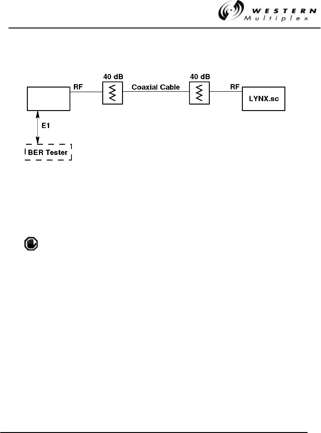
INSTALLATION AND MAINTENANCE MANUAL
LYNX.sc E1 FAMILY
SPREAD SPECTRUM RADIOS
SEPTEMBER 1999
SECTION 4: TROUBLESHOOTING PAGE 4-23
Figure 4-1: Back-to-Back Test Configuration
(When using a BER tester, initiate loopback on connected LYNX.sc and select external test mode
as described in Section 3.12.2).
The LYNX.sc radios will be damaged if appropriate attenuation is
not supplied between radios. You must provide a minimum of 40
dB and no more than 80 dB attenuation between the two radios.
LYNX.sc
LYNX.sc
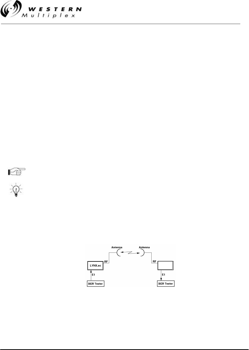
INSTALLATION AND MAINTENANCE MANUAL
LYNX.sc E1 FAMILY
SPREAD SPECTRUM RADIOS
SEPTEMBER 1999
PAGE 4-24 SECTION 4: TROUBLESHOOTING
4.10 BER (Bit Error Rate) Testing
Bit error rate (BER) testing is the preferred way to evaluate a radio link’s performance. It can be
performed from end-to-end or in loopback mode (which tests both directions of the radio path).
Figure 4-2 illustrates a typical BER test configuration for loopback testing (which may include the
radio’s path instead of in-line attenuators). Figure 4-2 illustrates a typical BER test configuration for
end-to-end testing.
When performing BER testing, make sure of the following:
- Disconnect all CEPT-1 inputs and outputs to both radios.
- Connect BER tester to bantam jacks or data in/output connector(s)
- Select external test signal for loopback testing using the DIP switches as defined in
Section 3.12.
- Verify all DIP switch settings.
- The BER test pattern chosen must contain adequate 1’s density
A 2
15-1, QRSS, or 3 in 24 test pattern may be used.
The LYNX.sc uses HDB3 line coding.
If two BER test sets are used to measure the link performance
separately in each direction, frame slips will occur unless the BER
test sets are synchronized with one test set as the master and the
other as the slave.
BER testing may be performed on the bench, with two terminals back to back, or over the radio
path. Also, it may be performed from end-to-end (which requires two BER test sets over a link, the
far-end unit slaved to the near-end unit’s clock) or in loopback mode, as described in Section 4.9.
If BER testing indicates an unacceptable level of errors, follow the instructions in Section 4.6.2. or
perform a back-to-back test as described in Section 4.9.
Figure 4-2: End-to-End BER Test Configuration

INSTALLATION AND MAINTENANCE MANUAL
LYNX.sc E1 FAMILY
SPREAD SPECTRUM RADIOS
SEPTEMBER 1999
SECTION 4: TROUBLESHOOTING PAGE 4-25
Your Notes on the LYNX.sc Radio

INSTALLATION AND MAINTENANCE MANUAL
LYNX.sc E1 FAMILY
SPREAD SPECTRUM RADIOS
SEPTEMBER 1999
SECTION 5: APPENDICES PAGE 5-1
5. Appendices
Appendix A - Digital Line Interface Specifications
Information in Appendix A is referenced to the following document: ITU-T G.703
1. General Characteristics
Bit rate: 2048 kbits/s ±50 ppm
Code: HDB3
2. Specifications at the output ports
Bit Rate 2.048 Mb/s
Pulse Shape All marks of a valid signal must conform with the mask irrespective of
the sign. The value V corresponds to the nominal peak value.
Pair(s) in each Direction One Coaxial pair
Test load impedance 75 ohms resistive
Nominal peak voltage
of a mark (pulse) 2.37 V
Peak voltage of a space
(no pulse) 0 ±0.237 V
Nominal pulse width 244 ns
Ratio of the amplitudes
of positive and negative
pulses at the center of
the pulse interval
0.95 to 1.05
Ratio of the widths of
positive and negative
pulses at the nominal
half amplitude
0.95 to 1.05
Table A-2: CEPT-1 Interconnection Specification
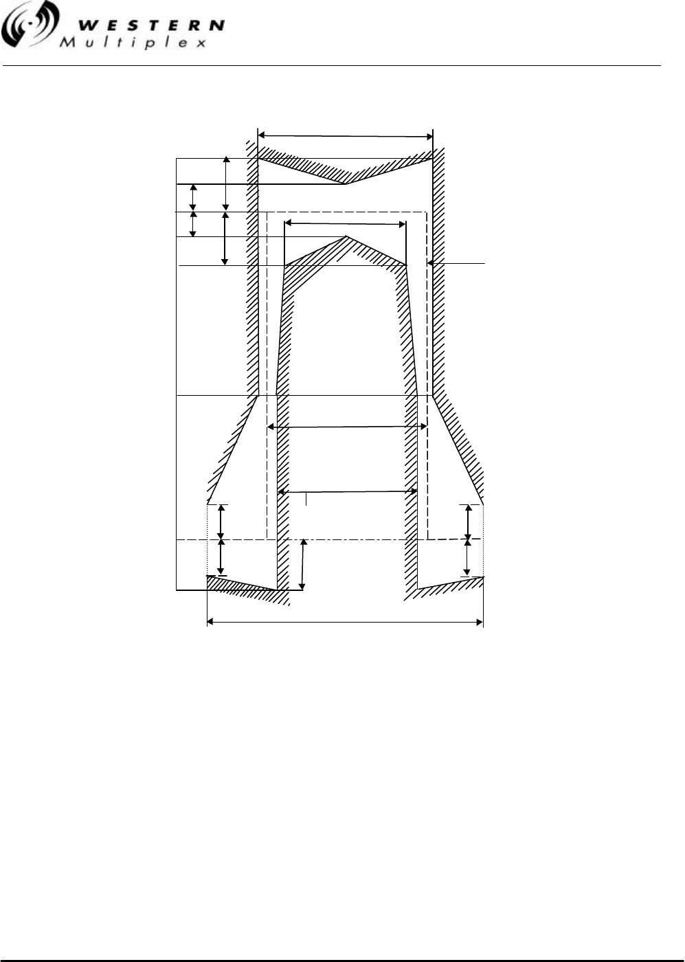
INSTALLATION AND MAINTENANCE MANUAL
LYNX.sc E1 FAMILY
SPREAD SPECTRUM RADIOS
SEPTEMBER 1999
PAGE 5-2 SECTION 5: APPENDICES
Figure A-1: Mask of the E1 Pulse (CEPT-1)
219
10%
10% 10%
10%
10%
10%
269
(244 + 25)
194 ns
(244 – 50)
244 ns
20%
488 ns
(244 + 244)
20%
20%
V=100%
50%
0%
Nominal pulse
CCITT-32540
Note – V corresponds to the nominal peak

INSTALLATION AND MAINTENANCE MANUAL
LYNX.sc E1 FAMILY
SPREAD SPECTRUM RADIOS
SEPTEMBER 1999
SECTION 5: APPENDICES PAGE 5-3
Appendix B - Rear Panel DIP Switches
The LYNX.sc radio has two separate eight-segment rear panel DIP switches, labeled SW1, and
SW3. Upon shipment from the factory, these switches are set for factory default configuration,
which is all switches down (in the “zero” position), except for SW3 positions 5 through 8, which are
set to match the installed rear panel RF filter assembly (which determines the frequency channel for
transmit and receive, such as A1, A2, B1, B2, etc.). The tables in this section provide a quick
reference for the DIP switch functions and their settings.
DIP switch settings are noted by their position, either up (1), or down (0),
not by on/off as may be printed on the DIP switch assembly.
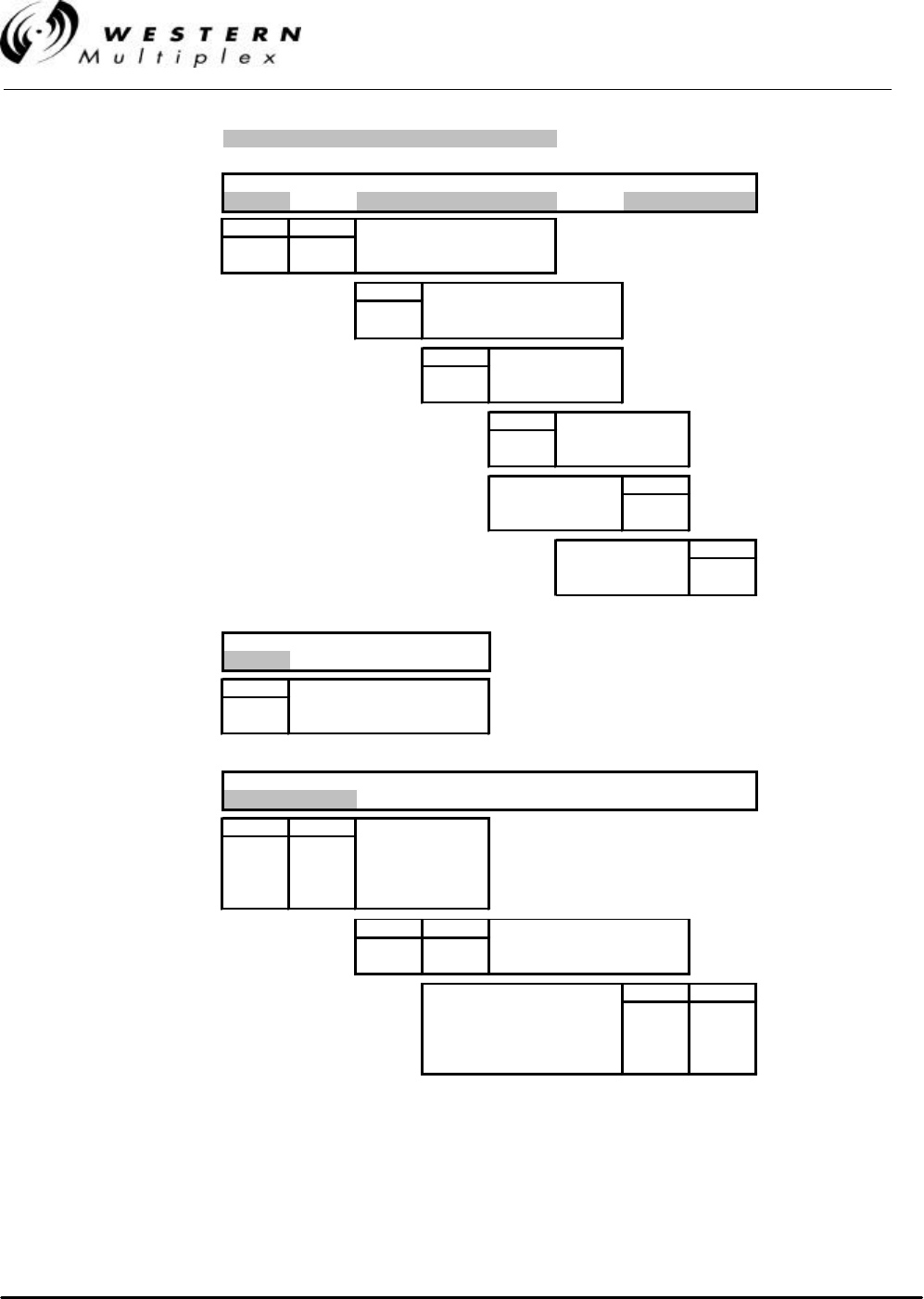
INSTALLATION AND MAINTENANCE MANUAL
LYNX.sc E1 FAMILY
SPREAD SPECTRUM RADIOS
SEPTEMBER 1999
PAGE 5-4 SECTION 5: APPENDICES
Shaded switch positions are factory default
12345678
SW1 1
0 0 x000000
1 2 Loss of Input Data Alarm
0 0 Enable (depends on model)
1 1 Disable
3 Loopback Test Source
0 Internal
1 External
4 Error LED Latch
0 Enable
1 Disable (Flash)
5 Rx AIS Output
0 Enable
1 Disable
Diagnostics Port 7
TBOS 0
Craft 1
Aux Data Port 8
Bridged (TBOS) 0
Enabled (Clear) 1
1234
SW2 1
00000
1CEPT-1 Ground Note:
0Floating Not used
1Grounded on 2E/4E
12345678
SW3 1x x
0 0 0 x x 0 0 x x
1 2 Spreading Code
0 0 Code 1
0 1 Code 2
1 0 Code 3
1 1 Code 4
3 4 Loss of Input Data Alarm
0 0 Enable (depends on model)
1 1 Disable
Frequency Xmtr Rcvr 7 8
A1 2410 2453 0 0
A2 2453 2410 0 1
B1 2430 2473 1 0
B2 2473 2430 1 1
Table B-1: LYNX.sc 2.4 GHz 1xE1, 2xE1 & 4XE1 Switch Settings
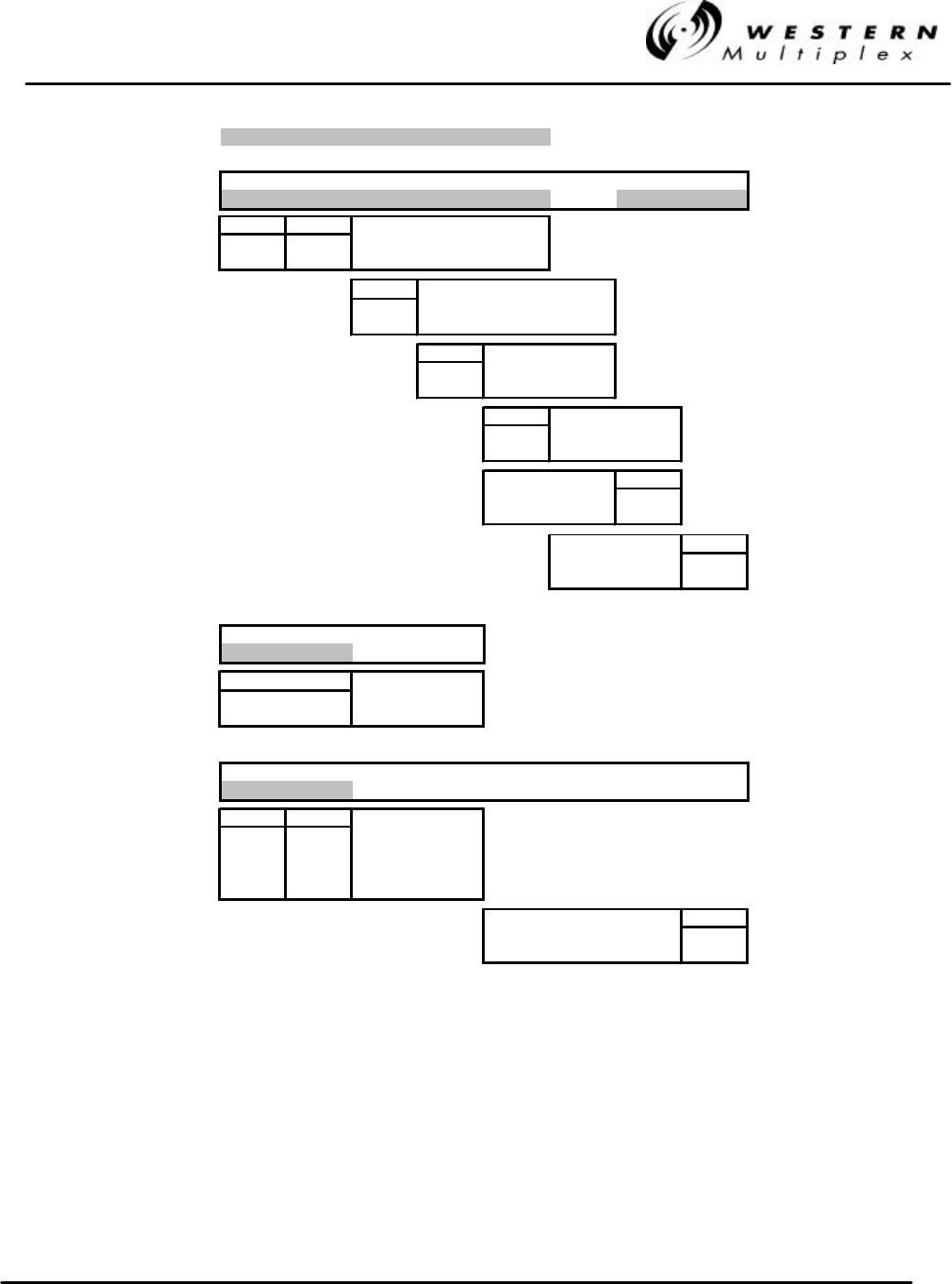
INSTALLATION AND MAINTENANCE MANUAL
LYNX.sc E1 FAMILY
SPREAD SPECTRUM RADIOS
SEPTEMBER 1999
SECTION 5: APPENDICES PAGE 5-5
Shaded switch positions are factory default
12345678
SW1 1
000000000
1 2 Loss of Input Data Alarm
0 0 Enable
1 1 Disable
3 Loopback Test Source
0 Internal
1 External
4 Error LED Latch
0 Enable
1 Disable (Flash)
5 Rx AIS Output
0 Enable
1 Disable
Diagnostics Port 7
TBOS 0
Craft 1
Aux Data Port 8
Bridged (TBOS) 0
Enabled (Clear) 1
1234
SW2 1
00000
1 2 CEPT-1 Ground
0 0 Floating
1 1 Grounded
12345678
SW3 1x
00000000x
1 2 Spreading Code
0 0 Code 1
0 1 Code 2
1 0 Code 3
1 1 Code 4
Frequency Xmtr Rcvr 8
A1 2421 2462.5 0
A2 2462.5 2421 1
Table B-2: LYNX.sc 2.4 GHz 2xE1 Switch Settings
INSTALLATION AND MAINTENANCE MANUAL
LYNX.sc E1 FAMILY
SPREAD SPECTRUM RADIOS
SEPTEMBER 1999
PAGE 5-6 SECTION 5: APPENDICES
1 2 3 4 5 6 7 8
SW1
1
0 0 0 0 0 0 0 0 0
1 Loss of Input Data Alarm
0 Enable
1 Disable
3 Loopback Test Source
0 Internal
1 External
4 Error LED Latch
0 Enable
1 Disable (Flash)
5 Rx AIS Output
0 Enable
1 Disable
Diagnostics Port 7
TBOS 0
Craft 1
Aux Data Port 8
Bridged (TBOS) 0
Enabled (Clear) 1
1 2 3 4
SW2
1
0 0 0 0 0
1CEPT-1 Ground
0Floating
1Grounded
1 2 3 4 5 6 7 8
SW3
1xxx
0 0 0 0 0 0 xxx
1 2 Spreading Code
0 0 Code 1
0 1 Code 2
1 0 Code 3
1 1 Code 4
Frequency Xmtr Rcvr 678
A1 5735 5800 000
A2 5800 5735 001
B1 5755 5820 010
B2 5820 5755 011
C1 5775 5840 100
C2 5840 5775 101
Table B-3: LYNX.sc 5.8 GHz 1xE1 Switch Settings
INSTALLATION AND MAINTENANCE MANUAL
LYNX.sc E1 FAMILY
SPREAD SPECTRUM RADIOS
SEPTEMBER 1999
SECTION 5: APPENDICES PAGE 5-7
Shaded switch positions are factory default
12345678
SW1 1
000000000
1 2 Loss of Input Data Alarm
0 0 Enable
1 1 Disable
3 Loopback Test Source
0 Internal
1 External
4 Error LED Latch
0 Enable
1 Disable (Flash)
5 Rx AIS Output
0 Enable
1 Disable
Diagnostics Port 7
TBOS 0
Craft 1
Aux Data Port 8
Bridged (TBOS) 0
Enabled (Clear) 1
1234
SW2 1
00000
1 2 CEPT-1 Ground
0 0 Floating
1 1 Grounded
12345678
SW3 1x x
0000000x x
1 2 Spreading Code
0 0 Code 1
0 1 Code 2
1 0 Code 3
1 1 Code 4
Frequency Xmtr Rcvr 7 8
A1 5741 5803 0 0
A2 5803 5741 0 1
B1 5772 5834 1 0
B2 5834 5772 1 1
Table B-4: LYNX.sc 5.8 GHz 2xE1 Switch Settings
INSTALLATION AND MAINTENANCE MANUAL
LYNX.sc E1 FAMILY
SPREAD SPECTRUM RADIOS
SEPTEMBER 1999
PAGE 5-8 SECTION 5: APPENDICES
Shaded switch positions are factory default
1 2 3 4 5 6 7 8
SW1 1
0 0 0 0 0 0 0 0 0
1 2 Loss of Input Data Alarm
0 0 Enable
1 1 Disable
3 Loopback Test Source
0 Internal
1 External
4 Error LED Latch
0 Enable
1 Disable (Flash)
5 Rx AIS Output
0 Enable
1 Disable
Diagnostics Port 7
TBOS 0
Craft 1
Aux Data Port 8
Bridged (TBOS) 0
Enabled (Clear) 1
1 2 3 4
SW2 1
0 0 0 0 0
1 2 3 4 CEPT-1 Ground
0 0 0 0 Floating
1 1 1 1 Grounded
1 2 3 4 5 6 7 8
SW3 1x x x
0 0 0 0 0 0 x x x
1 2 Spreading Code
0 0 Code 1
0 1 Code 2
1 0 Code 3
1 1 Code 4
3 4 Loss of Input Data Alarm
0 0 Enable
1 1 Disable
Frequency Xmtr Rcvr 6 7 8
A1 5735 5800 0 0 0
A2 5800 5735 0 0 1
B1 5755 5820 0 1 0
B2 5820 5755 0 1 1
C1 5775 5840 1 0 0
C2 5840 5775 1 0 1
Table B-5: LYNX.sc 5.8 GHz 4xE1 Switch Settings
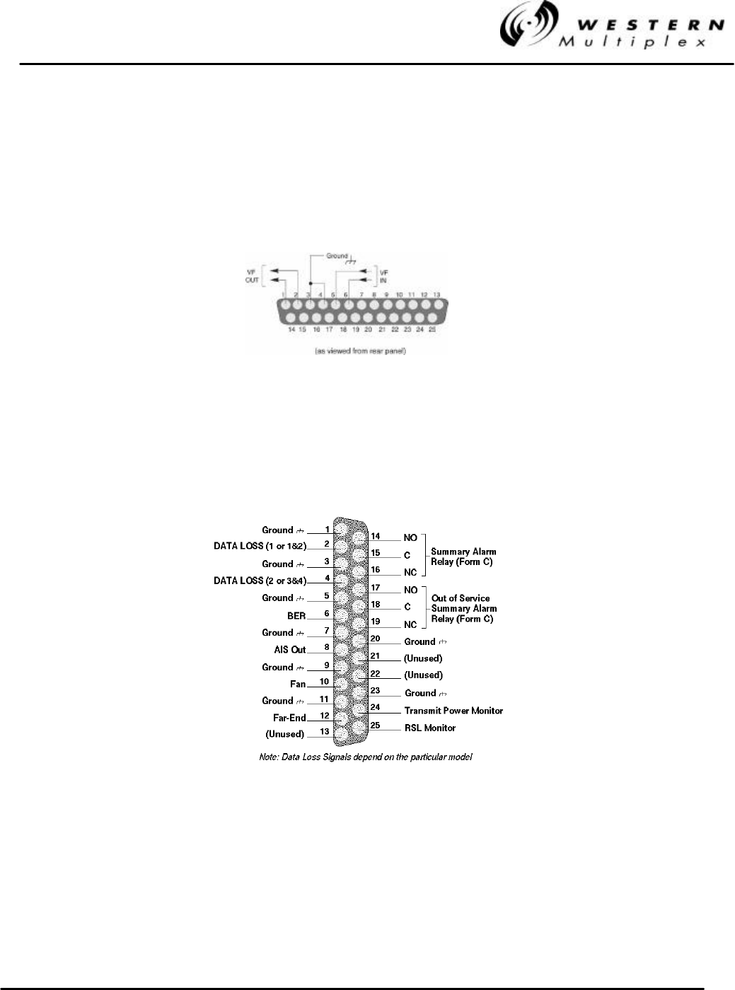
INSTALLATION AND MAINTENANCE MANUAL
LYNX.sc E1 FAMILY
SPREAD SPECTRUM RADIOS
SEPTEMBER 1999
SECTION 5: APPENDICES PAGE 5-9
Appendix C - Rear Panel Data Connectors
The following figures illustrate the pin structure for all rear panel data connections. All figures are
oriented as a customer would view them, facing the rear panel. DC power connection information is
found in Section 3.7 of the manual.
Figure C-1: VF Port Connection
Figure C-2: Alarm Port Connections
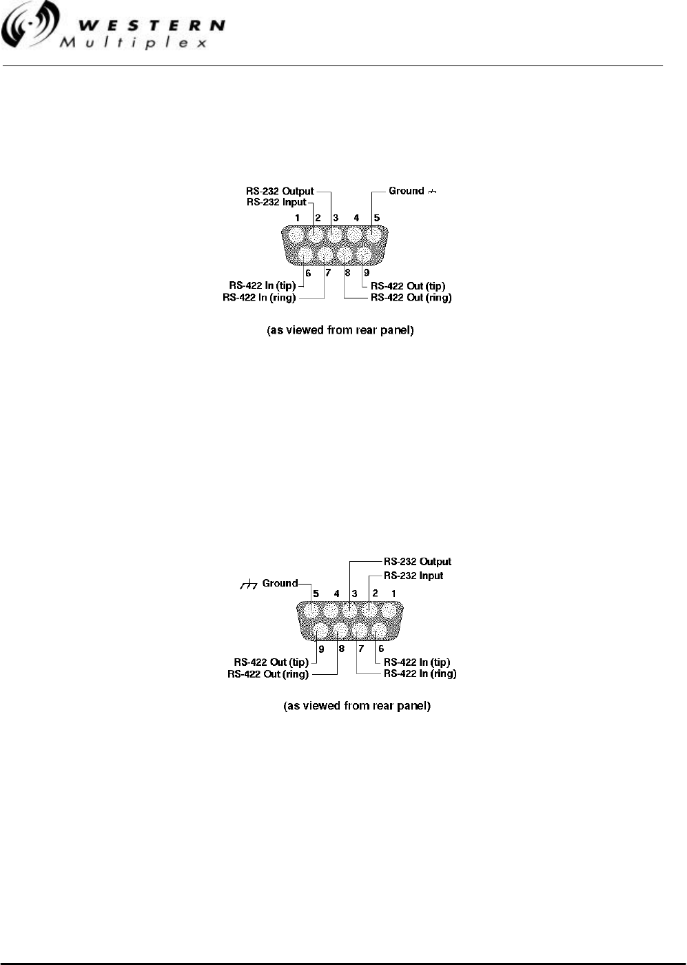
INSTALLATION AND MAINTENANCE MANUAL
LYNX.sc E1 FAMILY
SPREAD SPECTRUM RADIOS
SEPTEMBER 1999
PAGE 5-10 SECTION 5: APPENDICES
Figure C-3: Diagnostic Port 9-Pin D-Style Connector
Do NOT use both the RS-232 and RS-422 connections at the same time!
Figure C-4: AUX DATA Port 9-Pin D-Style Connector
Do NOT use both the RS-232 and RS-422 connections at the same time!

INSTALLATION AND MAINTENANCE MANUAL
LYNX.sc E1 FAMILY
SPREAD SPECTRUM RADIOS
SEPTEMBER 1999
SECTION 5: APPENDICES PAGE 5-11
Your Notes on the LYNX.sc Radio
Index
A
AC................................................................................................................................................................................. 3-19
Accessories ................................................................................................................................................................. 2-22
AIS .......................................................................................................................... 2-7, 2-13, 2-20, 3-29, 3-30, 3-47, 4-13
Alarm connections...................................................................................................................................................... 3-46
Alarm interface ............................................................................................................................................................ 3-47
Alarms ....................................................................................................................................................................3-36, 4-7
Alignment, antenna .................................................................................................................................................... 3-23
Antenna...................................................................................................................... 2-3, 3-3, 3-24, 3-36, 3-39, 4-9, 4-19
Antenna connection................................................................................................................................................... 3-20
Antenna installation................................................................................................................................................... 3-22
Antenna planning....................................................................................................................................................... 3-10
Availability calculation ................................................................................................................................................ 3-7
B
Balanced E1.................................................................................................................................................................. 2-18
Balun.............................................................................................................................................................2-7, 2-18, 3-25
Bit error rate ................................................................................................................................................................. 3-40
Bit Error Rate.......................................................................2-13, 2-14, 3-7, 3-30, 3-36, 3-41, 3-47, 4-9, 4-11, 4-17, 4-23
BNC............................................................................................................................................................................... 3-25
C
Calculations ................................................................................................................................................................... 3-5
Caution ........................................................................................................................................................................... 1-2
CEPT-1.................................................................................................................................................. 2-18, 3-25, 5-1, 5-2
CEPT-1 connection..................................................................................................................3-36, 3-40, 3-47, 4-7, 4-17
Channel plan.......................................................................................................................................................3-12, 3-26
Coaxial cable ................................................................................................................................................................ 3-21
Code.............................................................................................................................................................................. 3-28
Coding ............................................................................................................................................................................ 2-2
Connections.............................................................................................2-7, 2-8, 2-15, 2-17, 2-18, 2-19, 3-25, 3-36, 5-1
Container........................................................................................................................................................................ 3-1
Controls ........................................................................................................................................................................ 2-14
CSU/DSU...................................................................................................................................................................... 3-30
D
Data loss....................................................................................................................................................................... 3-29
DC...........................................................................................................................................................................3-9, 3-17
DIP switch.............................................................................................................................................................3-31, 5-3
DIP switch settings..................................................................................................................................................... 3-26
DIP switches ................................................................................................................................................................ 2-20
Dispersive fade.......................................................................................................................................................2-5, 3-6
E
EIRP............................................................................................................................................................................... 3-32
Environment................................................................................................................................................................... 2-9
Error LED ...................................................................................................................................................................... 3-42
Errors............................................................................................................................................................................. 4-17
F
Fade margin.................................................................................................................................................................... 3-6
Fans............................................................................................................................................................................... 4-14
Frequency .............................................................................................................................................................3-12, 4-2
Frequency plan.............................................................................................................................................................. 3-8
Fresnel............................................................................................................................................................................ 3-4
Front panel................................................................................................................................................................... 2-11
G
Grounding .................................................................................................................................................................... 3-17
H
HDB3......................................................................................................................................................................4-23, 5-1
I
Icons ............................................................................................................................................................................... 1-2
Installation ........................................................................................................................................... 1-1, 2-22, 3-3, 3-31
Interference.................................................................................................................................................................. 4-18
ISO 9000...............................................................................................................................................................................i
L
Line-of-sight .................................................................................................................................................................. 3-4
Link budget.................................................................................................................................................................... 3-5
Loopback..........................................................................................................................2-7, 2-14, 3-27, 3-40, 4-10, 4-17
M
Mechanical................................................................................................................................................................... 2-10
MHS.............................................................................................................................................................................. 3-56
Mounting ..................................................................................................................................................................... 3-15
N
Note................................................................................................................................................................................. 1-2
O
Orderwire .......................................................................................................2-8, 2-19, 2-21, 3-31, 3-36, 3-43, 3-44, 3-45
Output power......................................................................................................................................................3-33, 3-34
Output power, adjust................................................................................................................................3-37, 3-38, 3-39
P
Path ................................................................................................................................................................................. 3-4
Path planning............................................................................................................................................................... 3-10
Power...................................................................................................................2-2, 2-9, 2-22, 3-3, 3-16, 3-39, 4-9, 4-19
Power connection ....................................................................................................................................................... 3-16
Power connection, AC............................................................................................................................................... 3-19
Power connection, DC................................................................................................................................................ 3-17
Power supply planning ................................................................................................................................................ 3-9
Professional installation.......................................................................................................................................... iii, 1-1
R
Rear panel..............................................................................................................................................................2-16, 5-9
Receive signal level.............................................................2-12, 2-14, 3-3, 3-5, 3-22, 3-23, 3-24, 3-35, 3-47, 4-9, 4-20
Receiver.......................................................................................................................................................................... 2-4
Regulatory............................................................................................................................................................... iii, 2-10
REN ............................................................................................................................................................................... 3-43
Repair.............................................................................................................................................................................. 4-5
Repeater configurations....................................................................................................................................3-54, 3-55
RF filter......................................................................................................................................................................... 3-26
RS-232/RS-422 ........................................................................................................................2-19, 3-48, 3-49, 3-50, 3-53
RSL................................................................................................................................................................................ 3-24
S
SD Configuration ........................................................................................................................................................ 3-57
Shipping ................................................................................................................................................................2-22, 3-1
Spares ............................................................................................................................................................................. 4-3
Spreading code............................................................................................................................................................ 3-28
Switches ......................................................................................................................................................................... 4-2
Synchronization .......................................................................................................................................................... 4-12
System.....................................................................................................................................................................2-5, 2-6
T
TBOS...................................................................................................2-19, 2-20, 2-21, 3-43, 3-48, 3-51, 3-52, 3-53, 3-54
Technical support ......................................................................................................................................................... 4-4
Telephone .................................................................................................................................................................... 3-43
Test........................................................................................................................................................................2-8, 2-12
Tips ................................................................................................................................................................................. 1-2
Tools ............................................................................................................................................................................. 3-11
Transmission line........................................................................................................................................................ 3-21
Transmitter............................................................................................................................................................2-2, 3-37
Troubleshooting ........................................................................................................................................................... 4-1
Turn-up......................................................................................................................................................................... 3-31
W
Warranty ........................................................................................................................................................................... v
For ISO Purposes -
Last Page of this Manual