Proxim Wireless S58-GX1 Unlicensed DTS User Manual Lynx
Proxim Wireless Corporation Unlicensed DTS Lynx
UserManual.wiki
>
Proxim Wireless
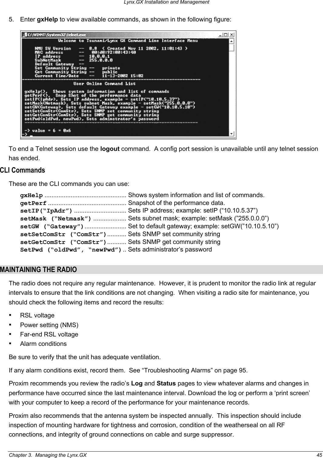
>
S58-GX1 User Manual
>
Manual Part 1
Contents
1.
Manual Part 1
2.
Manual Part 2
3.
Installation Manual
4.
Manual Pages 54 55
5.
Revised Installation Statement
Manual Part 1
Navigation menu
Upload a User Manual
Namespaces
Wiki Guide
HTML
PDF
Info
Views
User Manual
Discussion / Help
Navigation


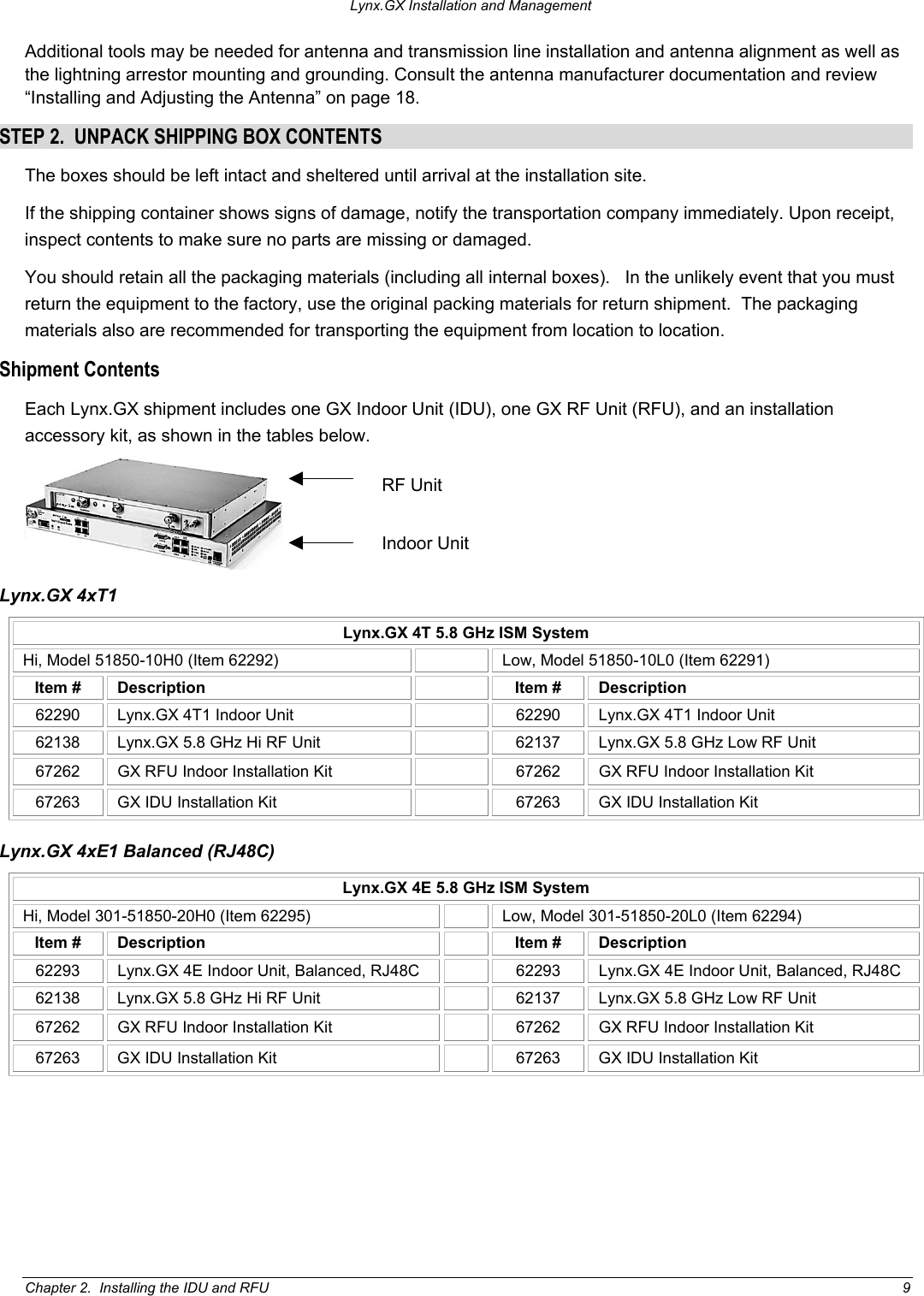


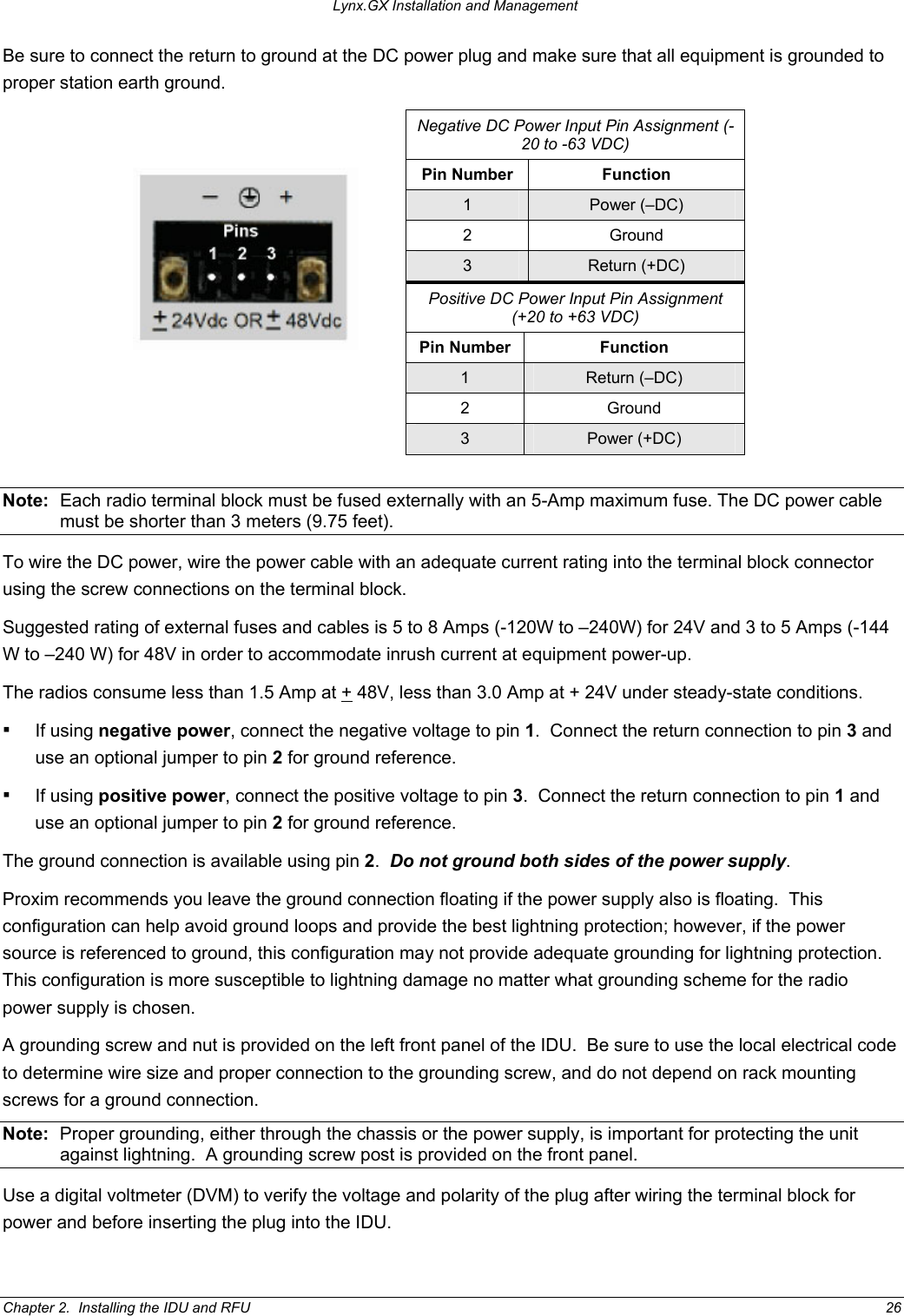
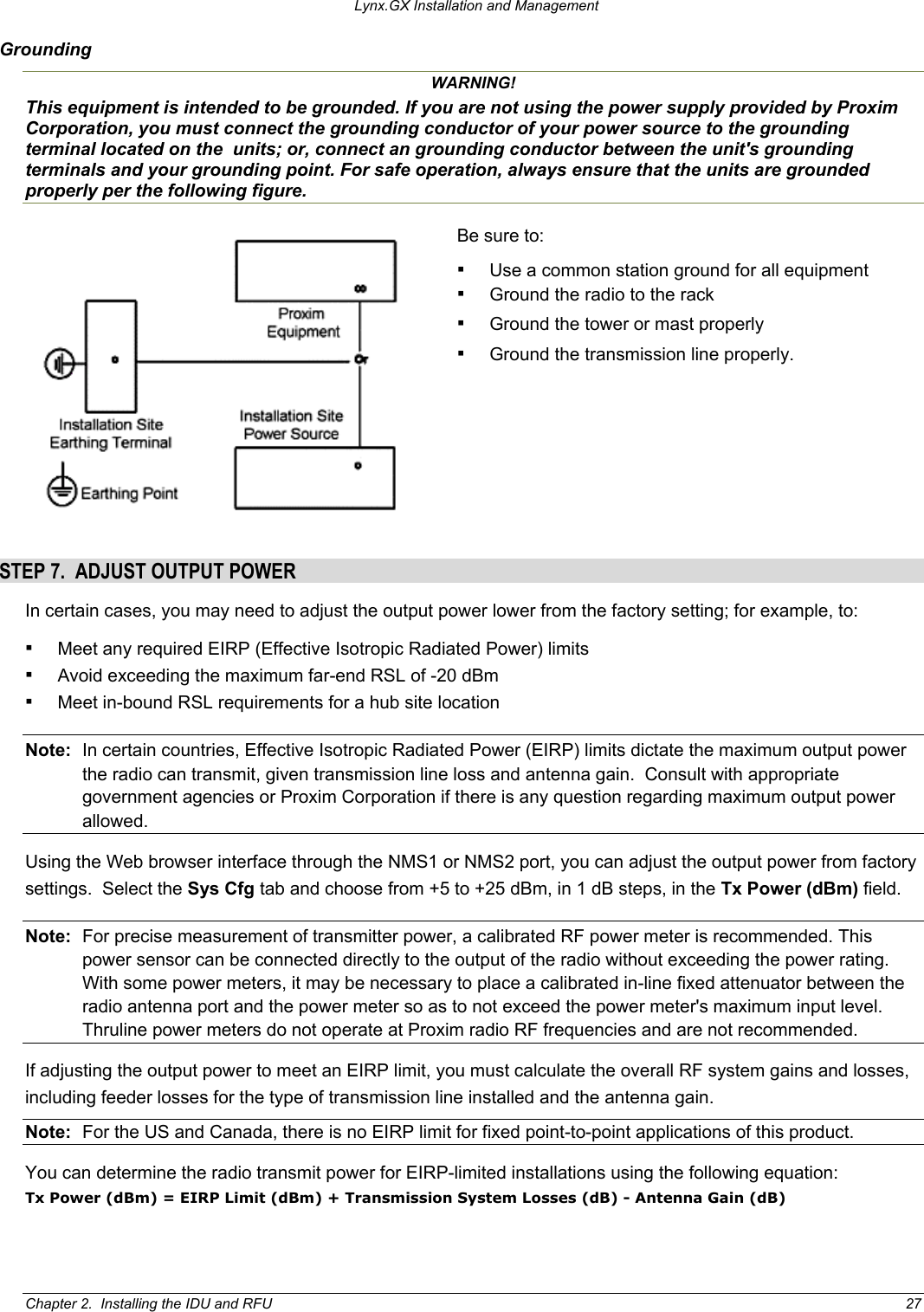
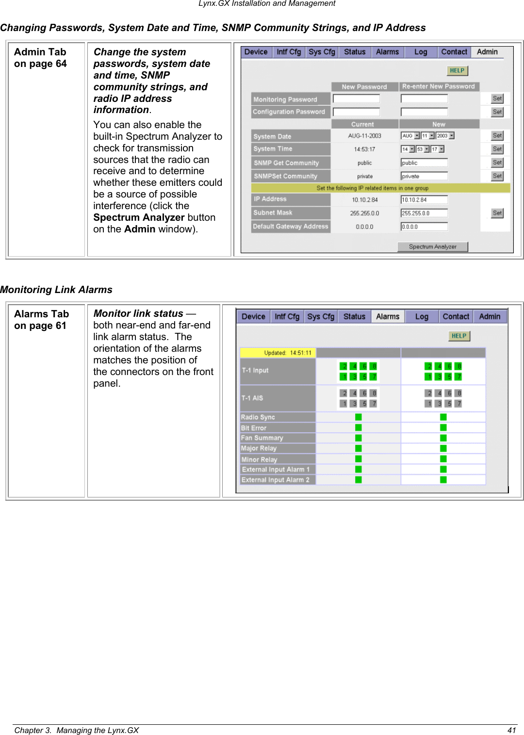
![Lynx.GX Installation and Management STEP 9. ESTABLISH NEAR-END TO FAR-END COMMUNICATIONS USING ORDERWIRE (OPTIONAL) To establish near-end to far-end communications using orderwire: 1. Connect telephones to the near-end and far-end radios. Using a standard RJ-11 telephone cable, connect a standard electronic telephone (a touch tone phone, complete with dialer, or DTMF phones) to the Orderwire connector on the radio front panel. This connector is wired identically to a standard two-wire telephone jack. For connector pin assignment, see “Connectors and Pin Assignments” on page 46. Note: If you are using a standard telephone (for orderwire function) not provided by Proxim with this product, ensure that the telephone has a ringing equivalency specification of 1.0 B or less and is a UL-Listed (ITE) device that has been evaluated to the Standard for the Safety of Information Technology Equipment, including Electrical Business Equipment, CAN/CSA C22.2, No. 950-85 * UL 1950, Third Edition. 2. Call the far-end radio. With a telephone connected to each radio on opposite ends of the link, either telephone can be used to dial-up the far-end location. The far-end radio internal ringer and the connected telephone ring, and if answered, two-way full-duplex voice communication is established. If the radios are connected in a repeater configuration, you can establish orderwire services in the network by connecting the radios (by cabling their front-panel VF connectors). The orderwire operates on radios at each end of the repeater and at the repeater site. You can extend this function through several repeater sites. For hub connections of three or more radios, an external 4-wire VF bridge (600 is required to connect all devices for orderwire operations. Dialing an * (asterisk/star key) on the orderwire telephone implements an “all call” feature that rings all connected radios. All telephones provide communication to all other telephones in the connected network. Even if a particular telephone does not ring, it can still be used to talk and listen to any ongoing orderwire activity if the orderwire is in use at other terminal locations. Also, if a phone anywhere in the connected network has accidentally been left off-hook, the # [pound] key can be used to mute all off-hook phones until they are placed on and off hook again. Chapter 2. Installing the IDU and RFU 31](https://usermanual.wiki/Proxim-Wireless/S58-GX1.Manual-Part-1/User-Guide-407168-Page-31.png)