Proxim Wireless S58-S60 Tsunami Multipoint Unlicensed Radio Transceiver User Manual Backing down from TNG CCI 2
Proxim Wireless Corporation Tsunami Multipoint Unlicensed Radio Transceiver Backing down from TNG CCI 2
Contents
- 1. Antenna Manual
- 2. Users Manual Part 2
- 3. Users Manual Part 1
- 4. Users Manual Part 1 cont
Users Manual Part 1

Tsunami Multipoint Version 1.3
Installation Manual
CPN 63179
Issue Date: 01/24/03
Copyright and Service Marks
Copyright © 2002 by Proxim Corporation. All rights reserved. No part of this manual may be reproduced
without prior written permission from Proxim Corporation.
The information contained in this manual is subject to change without notice. Proxim Corporation shall
not be liable for errors contained herein or for incidental or consequential damages in connection with the
furnishing, performance, or use of this manual or equipment supplied with this manual. Proxim
Corporation makes no warranty of any kind with regard to this manual or any equipment supplied with
this manual, including, but not limited to, the implied warranties of merchantability and fitness for a
particular purpose.
Tsunami™ is a registered product of Proxim Corporation.
Windows is a registered product of Microsoft Inc.
Other names are trademarks of their owners.
Y2K (Year 2000 Issue): All software supplied by and for Proxim Corporation products adhere to the four-
(4) digit year nomenclature as required for Year 2000 compliance.
Regulatory Notice
This equipment has been tested and found to comply with the limits for a class B digital device, pursuant
to Part 15 of the FCC Rules. These limits are designed to provide reasonable protection against harmful
interference in a residential installation. This equipment generates, uses and can radiate radio frequency
energy and, if not installed and used in accordance with the instructions, may cause harmful interference
to radio communications. However, there is no guarantee that interference will not occur in a particular
installation. If this equipment does cause harmful interference to radio or television reception, which can
be determined by turning the equipment off and on, the user is encouraged to try to correct the
interference by one or more of the following measures:
Reorient or relocate the receiving antenna.
Increase the separation between the equipment and receiver.
Connect the equipment into an outlet on a circuit different from that to which the receiver is connected.
Consult the dealer or an experienced radio/TV technician for help.
Shielded cables and I/O cords must be used for this equipment to comply with the relevant FCC
regulations.
Changes or modifications not expressly approved in writing by Proxim Corporation may void the user's
authority to operate this equipment.
This device complies with RSS-210 of Industry Canada. Operation is subject to the following two
conditions: (1) this device may not cause interference, and (2) this device must accept any interference,
including interference that may cause undesired operation of the device.
WARNING! This device must be professionally installed!

Tsunami Multipoint Version 1.3 Installation Guide
Contents
ABOUT THIS BOOK ...............................................................................................................5
Required Software and Firmware........................................................................................ 5
Safety Instructions...........................................................................................................6
CHAPTER 1. SITE PLANNING ...............................................................................................7
General Considerations .....................................................................................................7
Specific Considerations .....................................................................................................8
Interference and How to Avoid It...................................................................................... 10
Antennas ...................................................................................................................... 11
Path Planning ................................................................................................................ 14
PMP Radio Information ................................................................................................... 14
CHAPTER 2. DEPLOYING THE BASE STATION UNIT (BSU) ..................................................16
Unpacking the System .................................................................................................... 16
Mounting the Base Station Unit ........................................................................................ 17
Installing the GPS Antenna .............................................................................................. 24
Installing BSU Configuration Software............................................................................... 25
CHAPTER 3. DEPLOYING THE SUBSCRIBER UNIT...............................................................31
Mounting the Subscriber Unit (SU) ................................................................................... 31
Installing the Subscriber Utility Software ........................................................................... 34
Aiming the SU ............................................................................................................... 35
Displaying Link Status Information ................................................................................... 36
Confirming Network Activity ............................................................................................ 38
CHAPTER 4. SYSTEM DIAGNOSTICS AND OPERATING TIPS ...............................................40
Radio Diagnostics........................................................................................................... 40
Network Configuration Tips ............................................................................................. 44
Protecting the System .................................................................................................... 45
APPENDIX A. INITIAL SETTINGS .......................................................................................49
Specify the Desired Modulation (Data Rate) ....................................................................... 49
Specify the BSU’s Gateway Address.................................................................................. 49
Select the Routing Mode ................................................................................................. 49
Change the Frequency Plan and Operating Frequency.......................................................... 50
APPENDIX B. INSTALLING THE CONFIGURATION SOFTWARE AND UPGRADING
FIRMWARE ....................................................................................................................51
Base Station Configuration Software Version 1.5 ................................................................ 51
Subscriber Utility Software .............................................................................................. 54
Firmware Downloads ...................................................................................................... 54
APPENDIX C. TECHNICAL SPECIFICATIONS.......................................................................57
Burst-Rate Limit ............................................................................................................ 57
Downlink/Uplink Throughput............................................................................................ 57
Frequency Plans ............................................................................................................ 57
Tx Power ...................................................................................................................... 58
Antenna ....................................................................................................................... 58
Receiver Sensitivity........................................................................................................ 58
Maximum Distance Between Base Station and Subscriber Unit.............................................. 58
System......................................................................................................................... 59
Standards Compliance and Interfaces ............................................................................... 59
Configuration and Management........................................................................................ 59
Power/Environment Safety .............................................................................................. 60
Physical Dimension ........................................................................................................ 60
Installation Details ......................................................................................................... 61
Contents 3
CPN 63179 Issue Date: 01/24/03

Tsunami Multipoint Version 1.3 Installation Guide
Optional Accessories....................................................................................................... 61
APPENDIX D. CONSTRUCTING POWER AND ETHERNET CABLES.........................................62
Subscriber Unit Power and Ethernet Cable ......................................................................... 62
Assembling the RJ45 (Woodhead) Weatherproof Connector .................................................. 64
BSU Power and Ethernet Cable ........................................................................................ 65
Installing the AMP CPC Connector with Shield and Strain Relief............................................. 69
APPENDIX E. LIGHTNING PROTECTION RECOMMENDATIONS ...........................................70
Introduction .................................................................................................................. 70
Recommendation ........................................................................................................... 71
Physical Considerations................................................................................................... 72
Where Should the Protection Units be Located? .................................................................. 73
Lightning Protection Specifications.................................................................................... 73
APPENDIX F. TECHNICAL SUPPORT AND TRAINING ...........................................................76
Figures
Figure 1. BSU Wind Loading Analysis .......................................................................................................... 9
Figure 2. SU Wind Loading Analysis............................................................................................................ 9
Figure 3. BSU Azimuth Antenna Pattern .................................................................................................... 12
Figure 4. BSU Elevation Antenna Pattern................................................................................................... 12
Figure 5. SU Antenna Pattern .................................................................................................................. 13
Figure 6. Base Station Unit Components ................................................................................................... 16
Figure 7. BSU Mounting Hardware............................................................................................................ 18
Figure 8. U-Shaped Mounting Brackets Attached ........................................................................................ 18
Figure 9. Downtilt and Clamp Brackets with Screws Attached ...................................................................... 19
Figure 10. Bracket Assembly Detail of Screw, Washers, and Nut ..................................................................19
Figure 11. Bracket Assembly Attached to Mounting Bracket......................................................................... 20
Figure 12. Screws/Clamp Bracket Assemblies Attached............................................................................... 20
Figure 13. Strap Clamps Attached and Mounted BSU .................................................................................. 21
Figure 15. BSU’s Power and Ethernet Connector ........................................................................................ 21
Figure 16. GPS Antenna Mounted on BSU.................................................................................................. 24
Figure 17. Subscriber Unit Installation Kit ................................................................................................. 31
Figure 18. Mounting Clamp Housing and U-Bolts Attached........................................................................... 32
Figure 19. Mounting Bracket Attached to SU.............................................................................................. 32
Figure 20. Mounted SU ........................................................................................................................... 33
Figure 21. SU’s Power and Ethernet Connector and Grounding Screw ........................................................... 33
Figure 22. Settings Page in Subscriber Utility............................................................................................. 35
Figure 23. Aiming Tool in Subscriber Utility ............................................................................................... 36
Figure 24. Subscriber Utility Status Window .............................................................................................. 37
Figure 25. BSU Log in the Base Station Configuration Software.................................................................... 40
Figure 26. Log 1 .................................................................................................................................... 42
Figure 27. SU Log 2 ............................................................................................................................... 43
Figure 28. BER Log in Base Station Configuration Software ......................................................................... 44
Figure 29. Password Definition/Usage Diagram .......................................................................................... 47
Figure 30. Fresnel Zones......................................................................................................................... 58
Figure 31. 8-Pin DIN and RJ45 Contact Arrangements ................................................................................ 62
Figure 32. Soldered Wires on 8-Pin DIN Connector ..................................................................................... 63
Figure 33. Metal Shell Placed Over 8-Pin DIN Connector ............................................................................. 63
Figure 34. Jacket Placed Over 8-Pin DIN Connector .................................................................................... 64
Figure 35. Cat 5 Cable with Insulation Removed ........................................................................................ 64
Figure 36. Wires Crimped into RJ45 Connector .......................................................................................... 64
Figure 37. Woodhead Cover Placed Over RJ45 Connector ............................................................................ 65
Figure 38. End Nut Seated on RJ45 Connector ........................................................................................... 65
Figure 39. 18-Pin Positronic Connector ..................................................................................................... 65
Figure 40. BSU Power and Ethernet Cable Connectors ................................................................................ 66
Figure 41. Crimping Styles and Insertion .................................................................................................. 67
Figure 42. Indoor Portion of Power and Ethernet Cable ............................................................................... 67
Figure 43. Wire Preparation..................................................................................................................... 68
Figure 44. BSU Cable Construction Tools................................................................................................... 68
Figure 45. 8-Pin AMP Connector ............................................................................................................... 69
Contents 4
CPN 63179 Issue Date: 01/24/03

Tsunami Multipoint Version 1.3 Installation Guide
About This Book
The Tsunami Multipoint Quick Install Guide, Installation Manual, and Reference Manual comprise the
Tsunami Multipoint Version 1.3 documentation set.
▪ The Quick Install provides just enough information for the experienced professional to install the
Tsunami Multipoint system.
▪ This document, the Installation Guide, provides detailed installation information for the less
experienced professional to install and initially configure the Tsunami Multipoint system.
▪ The Reference Manual provides conceptual, advanced configuration, and command reference
information about the Tsunami Multipoint system. See the Reference Manual for information about:
º Routing modes
º Active Interference Rejection (A.I.R.)
º Priority Queuing
º Advanced Configuration Options
º Command Reference
º Troubleshooting
Required Software and Firmware
The required software and firmware codes for this official release are:
▪ BSU Console Version 1.4 or Version 1.5
▪ Subscriber Utility 1.1 (packaged with Console V1.5)
▪ BSU Firmware Version 1.3 binary code, identified as PMP_BSU_release1-3.mot
▪ SU Firmware Version 1.3 binary code, identified as PMP_SU_release1-3.mot
About This Book 5
CPN 63179 Issue Date: 01/24/03

Tsunami Multipoint Version 1.3 Installation Guide
Safety Instructions
WARNING! IMPORTANT SAFETY INSTRUCTIONS: DO NOT DISCARD!
▪ Review this guide for important installation instructions BEFORE you attempt to install this product.
▪ This product is intended to be installed, used, and maintained by experienced telecommunications
personnel only.
▪ This product has been evaluated to the U.S. and Canadian (Bi-National) Standard for Safety of
Information Technology Equipment, including Electrical Business Equipment, CAN/CSA C22.2,
No. 950-95 * UL 1950, Third Edition, including revisions through revision date March 1, 1998, which
are based on the Fourth Amendment to IEC 950, Second Edition. In addition, this product was also
evaluated to the applicable requirements in UL 1950, Annex NAE.
WARNING! This unit is intended for installation in accordance with Articles 110-18, 110-26, and
110-27 of the United States National Electric Code ANSI/NFPA 70; and per the
applicable Articles in the Canadian Electric Code.
▪ This equipment must be installed in accordance with Article 810 of the United States National
Electrical Code.
▪ Equipment is to be used with, and powered by, the power supplies provided only. A 15-Amp circuit
breaker is required at the power source.
▪ Lightening surge protection is provided by the power supplies included with this product. Do not use
any other devices for this purpose.
WARNING! This equipment is intended to be earthed. Use proper grounding methods. A 10 AWG
earthing conductor at a minimum is to be used for this purpose.
▪ Do not connect or disconnect the power cable to the equipment when the power supply is plugged in
an AC outlet.
▪ Servicing of this product should be performed by trained personnel only. Do not disassemble this
product. By opening or removing any covers you may expose yourself to hazardous energy parts.
Incorrect reassembly of this product can cause a malfunction, and/or electrical shock, when the unit
is subsequently used.
▪ Do not insert any objects of any shape or size inside this product while powered. Objects may contact
hazardous energy parts that could result in a risk of fire or personal injury.
▪ Do not spill any liquids of any kind on or inside this product.
▪ The maximum room ambient temperature (Tmra) for this product is 55°C. Consideration should be
given to installing this equipment in an environment compatible with the Tmra.
▪ Equipment is suitable for mounting on concrete or other noncombustible surface only.
▪ Do not remove or alter the Marking label provided on this product.
▪ The Base Station Unit operates at -48Vdc/1 A. The Subscriber Unit operates at +28Vdc/0.6 A.
About This Book 6
CPN 63179 Issue Date: 01/24/03

Tsunami Multipoint Version 1.3 Installation Guide
Chapter 1. Site Planning
The installation of a wireless network requires much the same basic planning as any wired network. The
main difference is that the wireless signal requires some additional planning. This planning includes RF
path planning, site preparation, and installation of outdoor components, such as outdoor units, antennas,
lightning protection devices, and cabling suitable for outdoor conditions.
Although the technology implemented in this broadband fixed wireless system can make use of multi-
path signals to reduce the effect of obstructions in the path, the characteristics of the path must be
carefully examined. With this knowledge, components and network requirements can be correctly
planned for your specific application.
This section provides insight into the planning necessary to prepare your site for your broadband fixed
wireless system.
General Considerations
A basic consideration is the physical location of the sites at each end of the link. Because microwave
signals travel in a straight line, a clear line-of-sight between antennas is ideal. Frequently, however, the
locations of the desired links are fixed. When you cannot achieve a clear line-of-sight, you must plan
accordingly.
Other general site considerations include:
▪ Whether a tower must be constructed (and whether permits are required)
▪ Possibility of future obstructions
º Will trees grow high enough to interfere with the signal? Are there plans to erect buildings
between the sites that may obstruct the path?
▪ Availability of grounding
º Good grounding is important. Also, in areas prone to lightning, a lightning arrestor is strongly
recommended.
▪ Distance between the indoor portion of the system and the user’s network.
▪ Whether the SU may potentially be served by different BSUs. Prior to installation, try to determine
the best BSU access and available sighting location.
▪ Whether strong RF interference exists in the neighborhood, within or adjacent to the operating
frequency.
The following sections are provided to help you determine which information is critical to your site, and to
aid in the decision-making process.
Chapter 1. Site Planning 7
CPN 63179 Issue Date: 01/24/03

Tsunami Multipoint Version 1.3 Installation Guide
Specific Considerations
Weather
You should research any unusual weather conditions common to the site location. These conditions can
include excessive amounts of rain, wind velocity, or extreme temperature ranges. If extreme conditions
exist that may affect the integrity of the radio link, take these conditions into consideration early in the
planning process.
Rain
Except in extreme conditions, attenuation (weakening of the signal) due to rain does not require serious
consideration for frequencies up to the range of 6 GHz. When microwave frequencies are at the 10-12
GHz range or higher, attenuation due to rain becomes much more of a concern, especially in areas where
rainfall is of high density and long duration. The systems discussed in this manual operate at frequencies
below 6 GHz, so rain is not a concern.
Temperature
Temperature can adversely affect the radio link when phenomena such as temperature inversion or very
still air accompanied by stratification occur. Temperature inversion can negate clearances; still air, along
with stratification, can cause severe refractive or reflective conditions, with unpredictable results.
Temperature inversions and stratification can also cause ducting, which may increase the potential for
interference between systems that do not normally interfere with each other. Where these conditions
exist, you should use shorter paths and adequate clearance.
Wind
Any system components mounted outdoors are subject to the effect of wind. You should know the
direction and velocity of the wind common to the site. Antennas and their supporting structures must be
able to prevent these forces from affecting the antenna or causing damage to the building or tower on
which the components are mounted. Antenna designs react differently to wind forces. This is known as
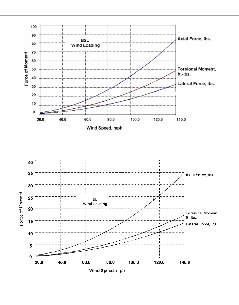
wind loading.
BSU and SU Wind Loading
Maximum operational wind speed during operation of BSUs and SUs is 50 m/s (112mph).
Survivable wind speed (tested to equivalent speed) is 90m/s (200mph).
The wind loading effect of the BSU and SU on their respective mounting masts is provided in Figure 1
(BSU) and Figure 2 (SU). The units of force in pounds can be converted to metric units by multiplying by
Chapter 1. Site Planning 8
CPN 63179 Issue Date: 01/24/03
Tsunami Multipoint Version 1.3 Installation Guide
4.45 to obtain newtons, or by 0.45 to obtain kilograms of force. Similarly, foot-pounds can be multiplied
by 1.36 to obtain Newton-meters, or by 0.138 to obtain kgm-meters.
Note: For definitions of wind loading specifications for antennas and towers, refer to TIA/EIA-195 (for antennas) or
TIA/EIA-222 (for towers) specifications.
Figure 1. BSU Wind Loading Analysis
Figure 2. SU Wind Loading Analysis
Chapter 1. Site Planning 9
CPN 63179 Issue Date: 01/24/03

Tsunami Multipoint Version 1.3 Installation Guide
Lightning
You should always consider the potential for lightning damage to radio equipment when planning a
wireless link. A variety of lightning-protection and grounding devices are available for use on buildings,
towers, antennas, cables, and equipment that could be damaged by a lightning strike, whether located
inside or outside the site.
Lightning protection requirements are based upon the exposure at the site, the cost of link down-time,
and local building and electrical codes. If the link is critical and the site is in an active lightning area,
attention to thorough lightning protection and grounding is critical.
Lightning Protection
To provide effective lightning protection, install antennas in locations that are unlikely to receive direct
lightning strikes, or install lightning rods to protect antennas from direct strikes. Make sure that cables
and equipment are properly grounded to provide low-impedance paths for lightning currents. Install
surge suppressors on adjacent telephone lines and power lines.
Users should provide additional lightning protection for cables leading to the wireless radio as well as to
and from the power supply in regions that have extreme lightning occurrences. This optional lightning
protection should be placed at points close to where the cable passes through the bulkhead into the
building, as well as near the BSU/SU. A grounding screw is provided on the BSU and SU.
For indoor applications, you can use the Erico LAN-RJ45 Local Area Network Protector (see Erico’s web
site, http://www.erico.com for information); for outdoor applications, you can use lightning protectors
from PolyPhaser (see the Polyphaser web site, http://www.polyphaser.com ).
See “Appendix E. Lightning Protection Recommendations” on page 70 for more information.
Category 5 Cable
When the entire power and Ethernet cable is encased in steel conduit from the building entrance to the
radio, no surge arrestors are required. Otherwise, each power and Ethernet cable requires one surge
arrestor within two feet of the building entrance.
Interference and How to Avoid It
An important part of planning your broadband fixed wireless system is the avoidance of interference.
Interference can be caused by effects outside the system. Good RF planning can overcome most
interference challenges.
Note: The Tsunami Multipoint product line includes a BSU that provides spectrum shielding. This BSU model can
reject interference at the uplink location. If interference from other systems is a problem, Proxim
recommends you use a BSU equipped with this feature.
Chapter 1. Site Planning 10
CPN 63179 Issue Date: 01/24/03

Tsunami Multipoint Version 1.3 Installation Guide
Co-Channel and Adjacent Channel Interference
Co-channel interference results when another RF link is using the same channel frequency. Adjacent-
channel interference results when another RF link is using an adjacent channel frequency. In selecting a
site, a spectrum analyzer can be used to determine whether any strong signals are present and, if
present, determine how close they are to the desired frequency. The further removed from your
proposed frequency, the less likely they are to cause a problem.
Antennas
Antennas frequently play a key role in reducing the potential for interference. They come in a variety of
configurations that have different performance characteristics in the areas of gain and direction. Antennas
that transmit/receive in all directions are known as omni-directional, while those that transmit/receive
in one specific direction are categorized as directional. Antennas also vary in beamwidth, which is the
aperture to which they can “see” signals. Larger antennas typically provide narrower beamwidths and
can diminish interference from nearby transmitters by:
▪ Focusing RF energy from the intended destination
▪ Reducing the power of interfering sources not directly aligned to the antenna
Tsunami Multipoint Ethernet Systems use integrated directional antennas that transmit and receive a
relatively narrow beamwidth of radio energy, improving system performance by reducing the likelihood
that surrounding RF clutter will interfere with reception. The antennas with this system are directional
and cannot be detached.
Chapter 1. Site Planning 11
CPN 63179 Issue Date: 01/24/03
Tsunami Multipoint Version 1.3 Installation Guide
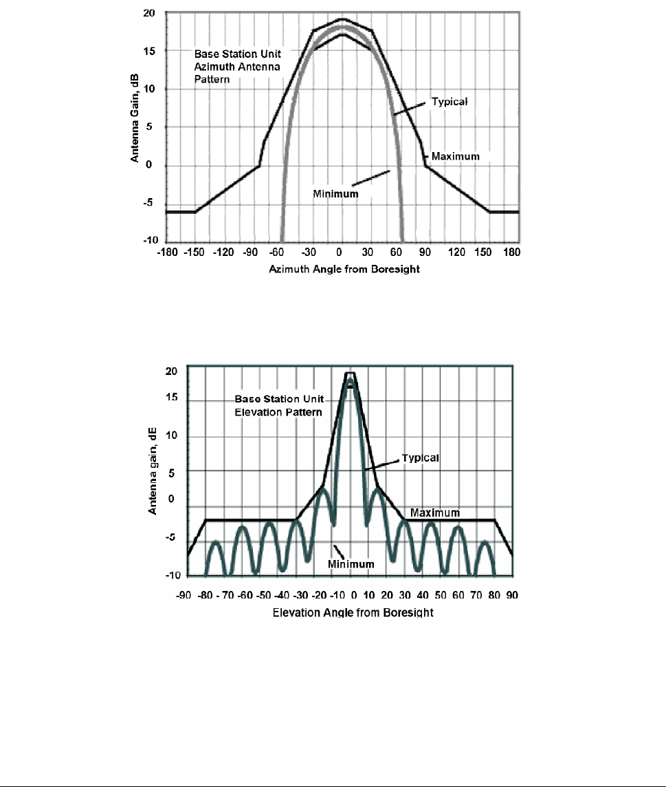
BSU Antenna Characteristics
Polarization: LHCP (Left-Hand Circular Polarization)
Azimuth Beamwidth: 60-degree
Elevation Beamwidth: 6-degree
Figure 3. BSU Azimuth Antenna Pattern
Figure 4. BSU Elevation Antenna Pattern
Chapter 1. Site Planning 12
CPN 63179 Issue Date: 01/24/03
Tsunami Multipoint Version 1.3 Installation Guide
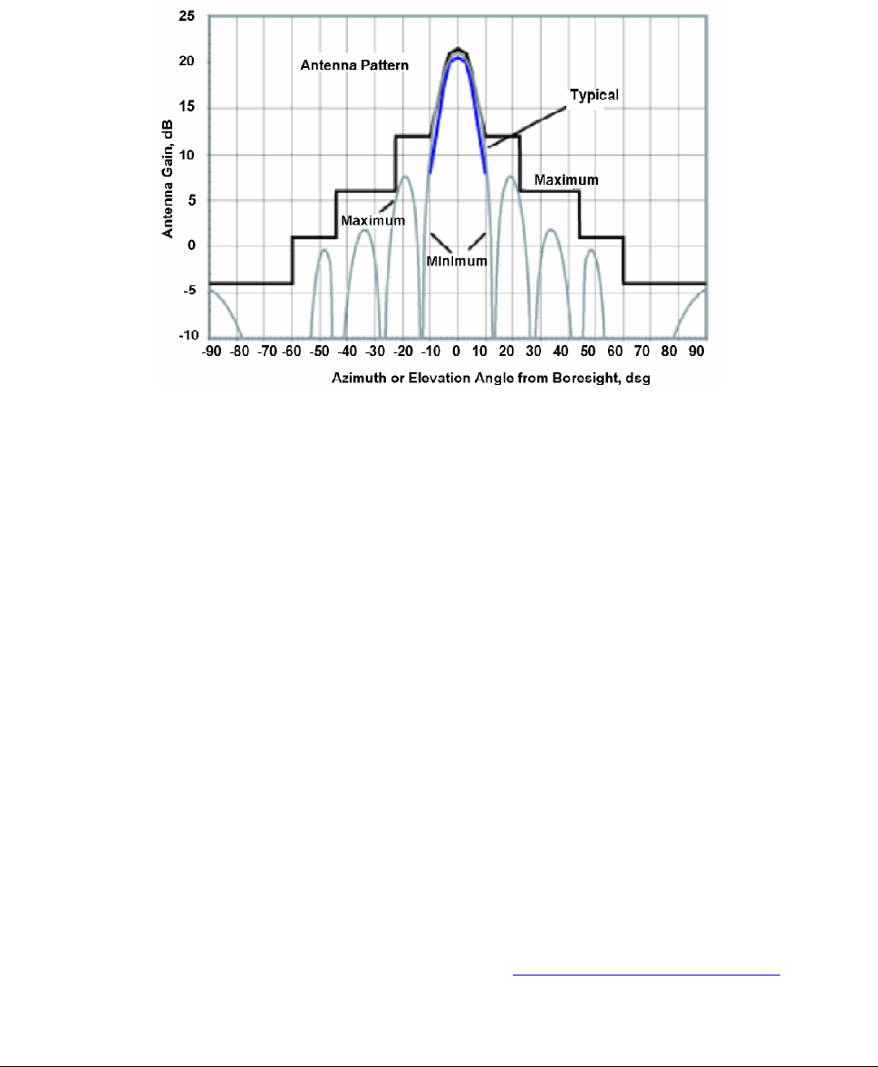
SU Antenna Characteristics
Polarization: LHCP
Beamwidth (Azimuth/Elevation): 10-degree
Figure 5. SU Antenna Pattern
Even when other licensees are not an issue, if you are using a network deployment using the “cell”
approach, all these considerations are still important for reducing interference between your own
adjacent installations. Antennas are tuned to operate on a specific group of frequencies.
Antenna Polarization
The Tsunami Multipoint system uses left-hand circular polarization. As a result, the signal is
successfully received regardless of the orientation of the antenna. Circular polarization also provides
protection against multi-path degradation of the signal quality.
Towers
When planning antenna placement, it might be necessary to build a free-standing tower for the antenna.
Regulations and limitations define the height and location of these towers with respect to airports,
runways, and airplane approach paths. These regulations are controlled by the FAA. In some
circumstances, the tower installations must be approved by the FAA, registered with the FCC, or both.
To ensure compliance, review the current FCC regulations regarding antenna structures. These
regulations (along with examples) are on the FCC web site at http://wireless.fcc.gov/antenna/ .
Chapter 1. Site Planning 13
CPN 63179 Issue Date: 01/24/03

Tsunami Multipoint Version 1.3 Installation Guide
Path Planning
To get the most value from a wireless system, path planning is essential. In addition to the fact that
radio signals dissipate as they travel, many other factors operate on a microwave signal as it moves
through space. All of these must be taken into account, because any obstructions in the path can
attenuate the signal.
Calculating a Link Budget
A link budget is a rough calculation of all known elements of the link to determine whether the signal
will have the proper strength when it reaches the other end of the link. To make this calculation, consider
the following information.
▪ A signal degrades as it moves through space. The longer the path, the more loss it experiences. This
free-space path loss is a factor in calculating the link viability. Free-space path loss is easily
calculated for miles or kilometers.
▪ Availability represents the quality of a link. It is the ratio of the time that the link is available to the
total time. This serves as a guide to the service you can expect, on the average, over a period of one
year.
You can lower the bit error rate (BER), resulting in greater reliability, by reducing the data throughput or
reducing the distance between the BSU and the SU.
Note: In terrestrial communication, path loss does not necessarily follow 20dB per decade degradation as used in
free-space loss. Instead, 25-35 dB per decade is more common in a metropolitan near-line-of-sight
environment.
Unlicensed Frequencies (U-NII)
The FCC has identified the frequencies from 5.725 to 5.825 GHz as Unlicensed National Information
Infrastructure (U-NII). This band can be used by anyone without having to obtain a license. However, you
must use radio equipment that is “type approved” by the FCC or local government for use within the
specific band.
PMP Radio Information
The following sections provide information about the Tsunami Multipoint radio components. See
“Appendix C. Technical Specifications” on page 57 for product technical specifications.
Chapter 1. Site Planning 14
CPN 63179 Issue Date: 01/24/03

Tsunami Multipoint Version 1.3 Installation Guide
Channel/Frequency Plans
Tsunami Multipoint offers several frequency plans to provide a means for overcoming interference. If one
part of the 5.8 GHz spectrum is occupied when you deploy the product, you can select a different
frequency plan to bypass the interfering frequency. Plan 4 is the default. Operating frequencies in the 5
and 6 plans overlap. See “Change the Frequency Plan and Operating Frequency” on page 50 for more
information.
Bandwidth
The Tsunami Multipoint offers four modulation modes: QAM16 (60 Mbps), QAM8 (40 Mbps), QPSK3Q (30
Mbps), and QPSK1H (20 Mbps) with equal bandwidth occupancy (3 dB BW at 20.75MHz, 26dB BW at
26MHz). Downlink and uplink signals are divided into time slots, with the number of slots per frame
varying, depending upon the current modulation mode and data rate. Furthermore, the ratio of slots
assigned to downlink and uplink is commandable (within limits; see “setFirstInboundSlot” in the Tsunami
Multipoint Version 1.3 Reference Manual for details)
Tx Power and Antenna Specifications
See “Tx Power,” “txPowerLevel,” and “Antennas” in the Tsunami Multipoint Version 1.3 Reference
Manual.
Power Control
Each SU automatically adjusts its transmit power so the strength of its signal at the BSU does not exceed
the limitation imposed by the Inbound Power Control (IPC) margin. This ensures fair access for all SUs
regardless of distance from the BSU. In addition, IPC can be increased to overcome interference. See
the “IPC” command in the Tsunami Multipoint Version 1.3 Reference Manual for more information.
Chapter 1. Site Planning 15
CPN 63179 Issue Date: 01/24/03
Tsunami Multipoint Version 1.3 Installation Guide
Chapter 2. Deploying the Base Station Unit (BSU)
This chapter describes how to mount and deploy the Base Station Unit including the GPS Antenna
(required when you install multiple BSUs at the same location).
Unpacking the System
The product’s shipping boxes should be left intact and sheltered until arrival at the installation site. If the
shipping container shows signs of damage, immediately notify the transportation company. Upon receipt,
inspect contents to make sure no parts are missing or damaged.
Proxim recommends that you retain all the packaging materials (including all internal boxes). In the
unlikely event that the equipment must be returned to the factory, use the original packing materials for
return shipment. The packaging materials are also recommended for transporting the equipment from
location to location.
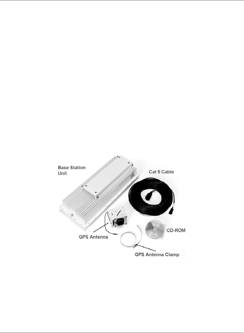
Unpack the following items from the contents of the shipping box. In addition to these items, you will
require an additional Cat 5 cross-over or straight-through cable (see step 5) and a BSU power adapter
(the BSU’s power supply is ordered and shipped separately; the power supply’s CPN number is 58526).
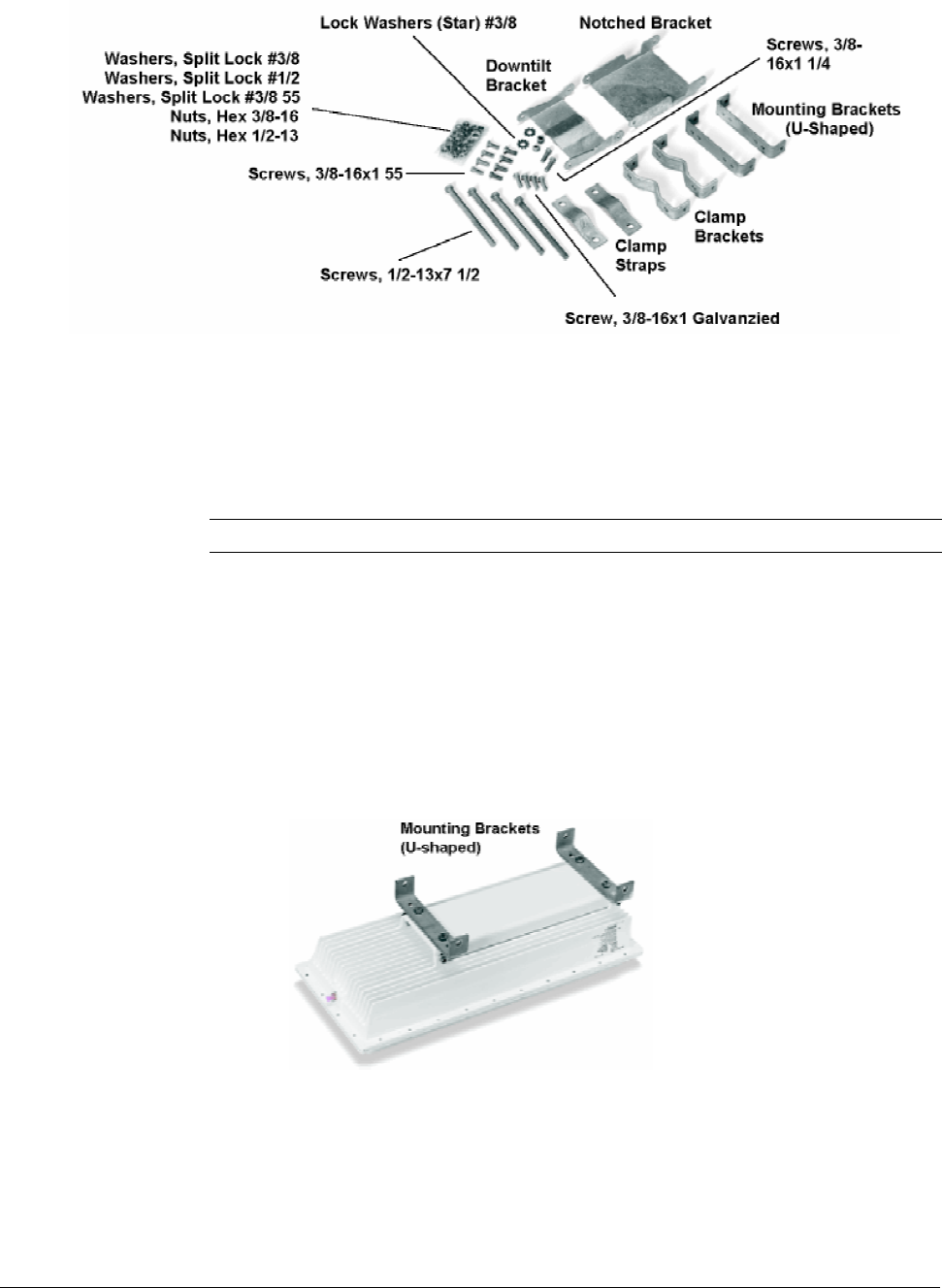
Figure 6. Base Station Unit Components
The product’s shipping boxes should be left intact and sheltered until arrival at the installation site. If the
shipping container shows signs of damage, immediately notify the transportation company. Upon receipt,
inspect contents to make sure no parts are missing or damaged.
Chapter 2. Deploying the Base Station Unit (BSU) 16
CPN 63179 Issue Date: 01/24/03

Tsunami Multipoint Version 1.3 Installation Guide
Proxim recommends that you retain all the packaging materials (including all internal boxes). In the
unlikely event that the equipment must be returned to the factory, use the original packing materials for
return shipment. The packaging materials are also recommended for transporting the equipment from
location to location.
Mounting the Base Station Unit
You can mount the outdoor component of your Tsunami Multipoint Base Station Unit directly to a pole
with an outside diameter of 1- ½ to 4- ½ inches.
Mounting the BSU is essentially a two-step process:
1. Assemble the BSU’s mounting components on the ground (ground work).
2. Mount the BSU to a pole using the mounting components.
Tsunami Base Station Unit System
Title Part Number Quantity
BSU Installation Kit, consisting of the following:
CD-Tsunami Multipoint Base Station CD
Assembly Cable, WAC, Cat 5, 50 M
Contact Kit, Positronic
Contact Kit, AMP
Mounting hardware (see the following table)
58686
100-00844-02
100-00861-00
100-00862-00
1 each
1 each
1 each
1 each
1 set
BSU Mounting Hardware
Mounting Hardware Part Number Quantity
Mounting Bracket Galvanized (U-Shaped) 200-01114-00 2 each
Screw, 3/8-16 x 1” Full Thread, Hex Head, SS316 720-01130-00 4 each
Washer, Split Lock, # 3/8, SS 316 730-01131-00 4 each
Notched Bracket 200-01115-00 1 each
Bracket, Downtilt 200-01116-00 1 each
Screw, 3/8-16 x 1 ¼ Full Thread, Hex Head, Galvanized 720-01120-00 6 each
Washer, Split Lock, #3/8, Galvanized 730-01122-00 10 each
Lockwasher, Int. and Ext., #3/8, Galvanized 730-01123-00 2 each
Nut, Hex, 3/8-16, Galvanized 740-01125-00 10 each
Bracket, Clamp (M-Shaped) 200-01117-00 2 each
Strap, Clamp 200-01118-00 2 each
Screw, 3/8-16 x 1” Full Thread, Hex Head 720-01119-00 4 each
Screw, 2/1-13 x 7 ½ Full Thread, Hex Head, Galvanized 720-01121-00 4 each
Washer, Split Lock, #1/2, Galvanized 730-01124-00 4 each
Nut, Hex, ½-13, Galvanized 740-01126-00 8 each
Screw, Machine, SEM, #10-32 x 3/8, Int Star 720-00580-00 5 each
Bracket, GPS Antenna Mtg 200-01083-00 1 each
GPS Antenna, WAC Transceiver 100-00754-00 1 each
Clamp, Band, 2” – 5” Diameter, SS Quick Rel 720-01127-00 1 each
Chapter 2. Pre-Installation Tasks 17
CPN 63179 Issue Date: 01/24/03
Tsunami Multipoint Version 1.3 Installation Guide
Figure 7. BSU Mounting Hardware
Required Tools: 9/16” (14-23 mm) wrench
6” (155 mm) crescent wrench
Note: Torque all #3/8 bolts and nuts 250 ± 10 in-lbs.
BSU Mounting: Ground Work
To assemble the BSU’s mounting components:
1. Place the BSU face (transmitter side) down on a flat surface.
2. Attach the two (u-shaped) galvanized mounting brackets to the back of the BSU using the four
stainless steel 3/8-16, hex head screws and four #3/8 split lock washers (see the following photo).
Figure 8. U-Shaped Mounting Brackets Attached
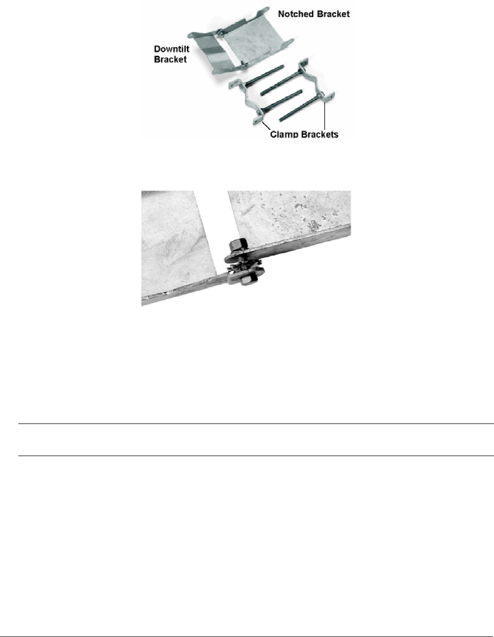
3. Insert two 1/2-13x7 1/2 screws through one of the clamp brackets (m-shaped) and secure the bolts
using two 1/2-13 hex nuts. Repeat this step for the other set of 1/2-13x7 1/2 screws, clamp bracket,
and 1/2-13 hex nuts (see Figure 9).
Chapter 2. Pre-Installation Tasks 18
CPN 63179 Issue Date: 01/24/03
Tsunami Multipoint Version 1.3 Installation Guide
4. Connect the downtilt bracket to the notched bracket using two 3/8-16x1 1/4 hex head screws, #3/8
split lock washers, #3/8 (star) lock washers, and 3/8-16 hex nuts (see Figure 9).
Figure 9. Downtilt and Clamp Brackets with Screws Attached
Figure 10. Bracket Assembly Detail of Screw, Washers, and Nut
5. Attach the downtilt/notched bracket assembly to the u-shaped mounting bracket near the middle of
the BSU using two sets of 3/8-16x1 1/4 hex head screws, #3/8 split lock washers, and 3/8-16 nuts.
Note: This mounting method lets you point the BSU down when mounted on a pole; to point the BSU up, attach
the downtilt/notched bracket assembly to the u-shaped mounting bracket near the bottom of the BSU.
Chapter 2. Pre-Installation Tasks 19
CPN 63179 Issue Date: 01/24/03